JP4167492B2 - Terminal assembly for elevator load support - Google Patents
Terminal assembly for elevator load support Download PDFInfo
- Publication number
- JP4167492B2 JP4167492B2 JP2002583311A JP2002583311A JP4167492B2 JP 4167492 B2 JP4167492 B2 JP 4167492B2 JP 2002583311 A JP2002583311 A JP 2002583311A JP 2002583311 A JP2002583311 A JP 2002583311A JP 4167492 B2 JP4167492 B2 JP 4167492B2
- Authority
- JP
- Japan
- Prior art keywords
- socket
- wedge
- brace member
- socket portion
- belt
- Prior art date
- Legal status (The legal status is an assumption and is not a legal conclusion. Google has not performed a legal analysis and makes no representation as to the accuracy of the status listed.)
- Expired - Fee Related
Links
Images


Classifications
-
- B—PERFORMING OPERATIONS; TRANSPORTING
- B66—HOISTING; LIFTING; HAULING
- B66B—ELEVATORS; ESCALATORS OR MOVING WALKWAYS
- B66B7/00—Other common features of elevators
- B66B7/06—Arrangements of ropes or cables
- B66B7/08—Arrangements of ropes or cables for connection to the cars or cages, e.g. couplings
- B66B7/085—Belt termination devices
-
- F—MECHANICAL ENGINEERING; LIGHTING; HEATING; WEAPONS; BLASTING
- F16—ENGINEERING ELEMENTS AND UNITS; GENERAL MEASURES FOR PRODUCING AND MAINTAINING EFFECTIVE FUNCTIONING OF MACHINES OR INSTALLATIONS; THERMAL INSULATION IN GENERAL
- F16G—BELTS, CABLES, OR ROPES, PREDOMINANTLY USED FOR DRIVING PURPOSES; CHAINS; FITTINGS PREDOMINANTLY USED THEREFOR
- F16G11/00—Means for fastening cables or ropes to one another or to other objects; Caps or sleeves for fixing on cables or ropes
- F16G11/04—Means for fastening cables or ropes to one another or to other objects; Caps or sleeves for fixing on cables or ropes with wedging action, e.g. friction clamps
- F16G11/044—Means for fastening cables or ropes to one another or to other objects; Caps or sleeves for fixing on cables or ropes with wedging action, e.g. friction clamps friction clamps deforming the cable, wire, rope or cord
- F16G11/046—Means for fastening cables or ropes to one another or to other objects; Caps or sleeves for fixing on cables or ropes with wedging action, e.g. friction clamps friction clamps deforming the cable, wire, rope or cord by bending the cable around a surface
-
- F—MECHANICAL ENGINEERING; LIGHTING; HEATING; WEAPONS; BLASTING
- F16—ENGINEERING ELEMENTS AND UNITS; GENERAL MEASURES FOR PRODUCING AND MAINTAINING EFFECTIVE FUNCTIONING OF MACHINES OR INSTALLATIONS; THERMAL INSULATION IN GENERAL
- F16G—BELTS, CABLES, OR ROPES, PREDOMINANTLY USED FOR DRIVING PURPOSES; CHAINS; FITTINGS PREDOMINANTLY USED THEREFOR
- F16G11/00—Means for fastening cables or ropes to one another or to other objects; Caps or sleeves for fixing on cables or ropes
- F16G11/04—Means for fastening cables or ropes to one another or to other objects; Caps or sleeves for fixing on cables or ropes with wedging action, e.g. friction clamps
- F16G11/044—Means for fastening cables or ropes to one another or to other objects; Caps or sleeves for fixing on cables or ropes with wedging action, e.g. friction clamps friction clamps deforming the cable, wire, rope or cord
- F16G11/048—Means for fastening cables or ropes to one another or to other objects; Caps or sleeves for fixing on cables or ropes with wedging action, e.g. friction clamps friction clamps deforming the cable, wire, rope or cord by moving a surface into the cable
-
- Y—GENERAL TAGGING OF NEW TECHNOLOGICAL DEVELOPMENTS; GENERAL TAGGING OF CROSS-SECTIONAL TECHNOLOGIES SPANNING OVER SEVERAL SECTIONS OF THE IPC; TECHNICAL SUBJECTS COVERED BY FORMER USPC CROSS-REFERENCE ART COLLECTIONS [XRACs] AND DIGESTS
- Y10—TECHNICAL SUBJECTS COVERED BY FORMER USPC
- Y10T—TECHNICAL SUBJECTS COVERED BY FORMER US CLASSIFICATION
- Y10T24/00—Buckles, buttons, clasps, etc.
- Y10T24/39—Cord and rope holders
- Y10T24/3969—Sliding part or wedge
- Y10T24/3971—Rope looped about movable member
-
- Y—GENERAL TAGGING OF NEW TECHNOLOGICAL DEVELOPMENTS; GENERAL TAGGING OF CROSS-SECTIONAL TECHNOLOGIES SPANNING OVER SEVERAL SECTIONS OF THE IPC; TECHNICAL SUBJECTS COVERED BY FORMER USPC CROSS-REFERENCE ART COLLECTIONS [XRACs] AND DIGESTS
- Y10—TECHNICAL SUBJECTS COVERED BY FORMER USPC
- Y10T—TECHNICAL SUBJECTS COVERED BY FORMER US CLASSIFICATION
- Y10T24/00—Buckles, buttons, clasps, etc.
- Y10T24/39—Cord and rope holders
- Y10T24/3996—Sliding wedge
-
- Y—GENERAL TAGGING OF NEW TECHNOLOGICAL DEVELOPMENTS; GENERAL TAGGING OF CROSS-SECTIONAL TECHNOLOGIES SPANNING OVER SEVERAL SECTIONS OF THE IPC; TECHNICAL SUBJECTS COVERED BY FORMER USPC CROSS-REFERENCE ART COLLECTIONS [XRACs] AND DIGESTS
- Y10—TECHNICAL SUBJECTS COVERED BY FORMER USPC
- Y10T—TECHNICAL SUBJECTS COVERED BY FORMER US CLASSIFICATION
- Y10T403/00—Joints and connections
- Y10T403/57—Distinct end coupler
- Y10T403/5793—Distinct end coupler including member wedging or camming means
-
- Y—GENERAL TAGGING OF NEW TECHNOLOGICAL DEVELOPMENTS; GENERAL TAGGING OF CROSS-SECTIONAL TECHNOLOGIES SPANNING OVER SEVERAL SECTIONS OF THE IPC; TECHNICAL SUBJECTS COVERED BY FORMER USPC CROSS-REFERENCE ART COLLECTIONS [XRACs] AND DIGESTS
- Y10—TECHNICAL SUBJECTS COVERED BY FORMER USPC
- Y10T—TECHNICAL SUBJECTS COVERED BY FORMER US CLASSIFICATION
- Y10T403/00—Joints and connections
- Y10T403/70—Interfitted members
- Y10T403/7001—Crossed rods
- Y10T403/7003—One rod is encompassed by the other
Description
本出願は、2001年4月18日に出願された同時に係属する出願番号09/837,825の出願の一部継続出願である。 This application is a continuation-in-part of the application filed on April 18, 2001, concurrently filed with application number 09 / 837,825.
本発明は、一般に、エレベータ支持システムに関する。さらに詳しくは、本発明は、エレベータシステムにおける荷重支持構成の端部を固定する装置に関する。 The present invention generally relates to elevator support systems. More particularly, the present invention relates to an apparatus for fixing an end of a load support arrangement in an elevator system.
エレベータシステムは、通常、ロープやベルトのような幾つかの形式の荷重支持構成を有し、昇降路内のかごを支持し、かつ、必要に応じて、移動させる。ある種の構成では、ベルトが、釣り合い重りとかごとを、繋ぐことになる。 Elevator systems typically have several types of load support configurations, such as ropes and belts, that support the car in the hoistway and move it as needed. In some configurations, the belt connects the counterweight and the car.
エレベータシステムの具体的な構成に拘わらず、通常、ベルトの端部をエレベータシステム内の適切な構造に固定することが、必要とされる。エレベータシステム内にベルト端部を固定する、種々の構成のアセンブリが使用されてきている。一例として、ベルトの一部分がソケットとウェッジとの間に固定される、鋳物製のソケット−ウエッジ構成が挙げられる。現状使用されている端末部の構成に関連した欠点の一つは、鋳造加工が比較的に高価なことである。さらに、通常必要とされる端末部の数量を掛け合わせることにより、さらに余分な費用が掛かり、望ましくないものとなってしまう。現状のシステムにおける別の欠点は、鋳造工程が、多くの構成で必要とされる寸法公差を実現するには、十分な精度となっていないことである。 Regardless of the specific configuration of the elevator system, it is usually required to secure the end of the belt to the appropriate structure within the elevator system. Various configurations of assemblies have been used to secure the belt ends within the elevator system. An example is a cast socket-wedge configuration in which a portion of the belt is secured between a socket and a wedge. One of the drawbacks associated with the currently used terminal configurations is that casting is relatively expensive. In addition, multiplying the quantity of terminal portions that are normally required results in additional costs and is undesirable. Another disadvantage of current systems is that the casting process is not accurate enough to achieve the dimensional tolerances required in many configurations.
従って、改良されたエレベータ荷重支持用端末部の構成が必要とされている。本発明は、前記必要性に対処しつつ、上述の欠点を克服し、加えて、大幅なコスト削減を可能とするものである。 Therefore, there is a need for an improved elevator load support terminal configuration. The present invention overcomes the above-mentioned drawbacks while addressing the above needs and, in addition, allows for significant cost savings.
概して言えば、本発明は、エレベータシステムにおける荷重支持部材の端部を固定する装置に関するものである。この装置は、押出成形されたソケットと押出成形されたウエッジとを備える。前記ソケットは内側表面を有し、その内側表面に、荷重支持部材の一部分が収容される。前記ウェッジは外側表面を有し、その外側表面は、前記ウエッジを前記ソケット内に配置したときに、荷重支持部材に接触する。少なくとも一つのブレス部材が、前記ソケットを支持し、前記ソケット内の所定の位置に前記ウエッジを保持するよう支援している。 Generally speaking, the present invention relates to an apparatus for securing an end of a load bearing member in an elevator system. The apparatus comprises an extruded socket and an extruded wedge. The socket has an inner surface on which a portion of the load bearing member is received. The wedge has an outer surface that contacts the load bearing member when the wedge is disposed in the socket. At least one brace member supports the socket and assists in holding the wedge in place within the socket.
好適な一つの実施例においては、前記ブレス部材は単品の押し出し鋼材である。荷重支持部材(すなわち、ベルト)の少なくとも一部分が、前記ブレス部材と前記ソケットとの間に収容されるのが望ましい。 In one preferred embodiment, the brace member is a single piece of extruded steel. Desirably, at least a portion of the load bearing member (ie, belt) is received between the brace member and the socket.
好適な一つの実施例においては、前記ウエッジと前記ソケットとが、荷重支持部材に接触する、互いに対応する表面を備える。前記係合用表面は、一定の形状を有していることが望ましい。一例として、荷重支持部材係合用の表面は、摩擦力を向上させる表面を有する。 In a preferred embodiment, the wedge and the socket comprise corresponding surfaces that contact the load bearing member. It is desirable that the engagement surface has a certain shape. As an example, the surface for engaging the load support member has a surface that improves the frictional force.
当業者であれば、次に説明する現状の好適な実施例の詳細な説明から、本発明の種々な特徴と長所とが、明らかになるだろう。詳細な説明に付随する図面に、以下に示すように、簡単な説明が付されている。 Various features and advantages of the present invention will become apparent to those skilled in the art from the following detailed description of the presently preferred embodiment. BRIEF DESCRIPTION OF THE DRAWINGS The accompanying drawings that accompany the detailed description can be briefly described as follows.
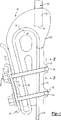
図1に示されているように、エレベータシステム内の荷重支持部材22の端部を留める装置20は、ソケット部24とウエッジ部26とを含む。図示の例における荷重支持部材22は、被膜されたスチールベルトである。しかし、本発明は、この被膜されたスチールベルトに限定されない。本発明によって設計されたソケット−ウエッジ構成を用いて収容されうる、エレベータシステムのいかなる荷重支持部材を使用してもよい。本明細書中に使用されている用語である「ベルト」は、厳密な意味で解釈されるべきものではない。前記「ベルト」は、ロープもしくは荷重支持部材と同義であると解釈すべきである。
As shown in FIG. 1, the
前記ソケット部24と前記ウエッジ部26とは、押出成形されることが望ましいが、さもなければ、板金の材料から作られる。押出し成形もしくは他の板金成形加工は、精密な寸法公差と製造費の節減とを達成する点で利点がある。押出し成形もしくは他の板金成形加工を使用することで、前記ソケット部24と前記ウエッジ部26との協働しあう表面を、厳密に平行とさせることができる。荷重支持部材22の端部を固定する上での安定性を確保するために、各表面は、一定の形状をなす断面を有することが望ましい。加えて、押出し成形もしくは他の板金成形加工を使用すれば、従来の鋳造工程の使用に比べ、50%のオーダーでコスト削減を可能とする。本明細書により当業者であれば、押出し成形もしくは他の成形加工が、個々の状況下での必要性に最も適したものであることが理解できよう。
The
前記ウエッジ部26は、外側表面28を有し、前記外側表面28は、前記ウエッジ部26が前記ソケット部24内に内挿されたときに、ベルト22に接触する。前記ソケット部24の内側表面30が、前記ベルト22の反対側と接触する。従って、前記ベルト22は、該ベルト22が所定の位置に保持されるように、前記ウエッジ部26と前記ソケット部24との間に固定される。好適な実施例においては、前記ウエッジ部の前記外側表面28は、摩擦力を向上させる表面を備える。一例として、前記外側表面は、いわゆる鋸歯形状の溝を備える。別の例では、前記ウエッジ部の前記外側表面28は、サンドブラストもしくは別の一般的な技術により、粗面とされる。同様に、前記ソケット部24の前記内側表面30も、摩擦力を向上させる質感を備えることが望ましい。
The
好適な構成では、少なくとも一つのブレス部材32を含み、該ブレス部材32は、前記ソケット部24のレッグ部33を所定の位置に保持し、それにより前記ウエッジ部26および前記ベルト22の対応する部分を固定する。図1〜図3の図示の例は、前記ブレス材として機能する2個のU字形ボルト32を含む。前記ソケット部24は、好適には押し出し加工で作られているため、エレベータシステムにおける荷重支持部材22が張力を受けると、前記ウェッジ部26に働く力により、前記ソケット部がこじあけられてしまいやすい。
In a preferred configuration, it includes at least one
前記U字形ボルト32の一部分34が、前記ソケット部24上に設けられた対応する面36に収容されることが望ましい。好適な構成では、各U字形ボルトの前記部分34が前記ソケット部24にはめこまれて所定の位置に固定されるような、収容部36の構造が含まれている。前記U字形ボルトは、前記ソケット部24の所定の位置にはめこまれた後は、前記部分34の軸を中心に回転できることが望ましい。前記ソケット部24の前記レッグ部分33を所定の位置に固定するために、従来のナット38が使用されることが望ましい。
A
図1〜図3に示されている実施例は、固定用部材40を含み、該部材40は、前記ソケット部24の外側表面に対し、荷重支持部材22の端部22’を固定する。図示例の固定用部材40は、スプリングクリップである。前記スプリングクリップは、望ましくは前記ブレス部材32と協働し、所定の位置に前記ベルトの端部22’を保持する。さらに、前記ベルト22のウレタン被膜部が損傷を受けた等の場合にも、前記スプリングクリップ40は、前記ベルト22内のスチール製荷重支持部材を所定の位置に保持するという目的を果たす。
The embodiment shown in FIGS. 1 to 3 includes a
前記スプリングクリップ40は、前記U字形ボルト32の対応する部分を収容するスロット部42を含むことが望ましい。組付中に、前記スプリングクリップ40が、所定の位置に置かれ、そして、前記U字形ボルトが、前記スロット部42内に適切に収容されるまで、前記部分34の軸の回りに回転する。その後、前記ナット38が適度に締められ、所定の位置に前記ベルト22の端部を適切に固定する。
The
前記ソケット部の外側表面は、このソケット部24の外側表面に前記ベルトの端部22’を保持させ易くするように、摩擦力を向上させる表面50を有することが望ましい。一つの実施例として、前記摩擦力を向上させる表面は、前記ベルトを効果的につかむ隆起した部分を外側表面上に備える。
The outer surface of the socket part preferably has a surface 50 for improving the frictional force so that the outer surface of the
前記アセンブリ20により、前記ベルト22の端部を、従来から必要なように、エレベータシステムの他の部分に固定することが容易となる。図示の例では、ネジ形の端部62を備えたロッド60が示され、該端部62は、前記ソケット部24のネジを有する開口部64に収容される。
The
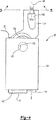
図4〜図7は、他の好適な実施例を示す。この実施例において、アセンブリ20’はソケット部124とウエッジ部126とを備え、これらは、前述の実施例におけるソケット部とウエッジ部と同様な方法で、協働する。該実施例の前記ウエッジ部126は、該ウエッジ部126の外側表面に沿って、摩擦力を向上させたベルト係合面128を備えていることが望ましい。前記ソケット部124の内側にあるベルト係合面130も同様な態様であることが望ましい。一例として、いわゆる鋸歯形状が、前記両部品のベルト係合面全体に渡っている。種々の表面構造あるいは摩擦力向上処理が、本発明の範囲内に含まれる。
4-7 show other preferred embodiments. In this embodiment, the assembly 20 'includes a
図1〜図3の実施例と比較して、図4〜図7の実施例における相違点の一つは、図4および図5で最も明らかなように、ブレス部材132が、押し出し加工金属部品からなることである。この実施例においては、前記ブレス部材はほぼ長方形をなしており、一体に作られている。前記押出成形されたブレス部材132は、ソケット部124とウエッジ部126と荷重支持部材22の該当する部分とを組み合わせた上に嵌合する。図示の前記ブレス部材132は、前記ソケット部124の外側表面の片側と接合する第1の内側表面134を有する。もう一方の内側表面136は、前記荷重支持部材22と接合することが望ましい。従って、前記ブレス部材132における前記表面136と前記ソケット部124のレッグ部140における前記外側表面138との間に、荷重支持部材22の一部分が収容される。前記表面136,138は、摩擦力を向上させる表面を備えるように作られるのが望ましく、それにより、前記荷重支持部材22の保持力がさらに向上する。
Compared with the embodiment of FIGS. 1-3, one of the differences in the embodiment of FIGS. 4-7 is that, as best seen in FIGS. 4 and 5, the
前記ソケット部124は、2つのレッグ部を有することが望ましい。一方のレッグ部140が、組み付け後、前記ウエッジ部126の一方の側に配置され、同時に他方のレッグ部142が、前記ウエッジ部の他方の側に配置される。前記レッグ部142は、該レッグ部142の一方の終端付近に、突起144を有することが望ましい。前記突起144は、組付時に、前記ソケット部124における前記ブレス部材132の保持を容易にする。
The
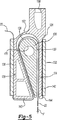
前記レッグ部140を、レッグ部142に対し、初期状態で2つのレッグ部の外側表面が互いに平行にならないように配列することが望ましい。図示の例では、前記レッグ部140上の前記外側表面138は、前記レッグ部142の外側表面の配置に対し、所定の角度150をもって配置されている。この平行ではない配列は、前記ソケット部124の成形時の押し出し加工の間に構成されることが望ましい。組付中および前記端末装置20’の使用中に、前記レッグ部140を前記レッグ部142と平行となるように動かせるように、前記ソケット部の一部分152が十分に撓むことが望ましい。
The
図5および図6を参照すると、前記ベルトつまり荷重支持部材22は、前記ウェッジ部126の前記外側表面128の周囲に沿って固定されることが望ましい。また、最初に、前記ベルト22の選択された部分を前記ブレス部材132の開口部内に通しておくことも、好適である。前記ベルト22の所定の部分を、前記ウエッジ部126の外側128の周囲に包んだ後、前記ベルト22と前記ウエッジ部126とを、前記ソケット部124内に内挿することが望ましい。図示の構成により、前記ウエッジ部と前記ベルトとを側方から(つまり、図5の紙面に向かう方向に)内挿することを可能とする。それから、前記表面136と前記表面138との間に前記ベルト22の所定部分を保持させながら、前記ブレス部材132が、前記ソケット部材124上をスライドさせられることが望ましい。前記レッグ部142の前記突起144は、前記ソケット部124上の所定の位置に、前記ブレス部材132を保持するよう機能する。前記ウエッジ部126を(図示のように)下方に引く力Fが働くと、前記レッグ部140は、前記レッグ部142と平行な配列となるように移動し、そして、前記荷重支持部材22は、前記ソケット部124と、前記ウエッジ部126と、前記ブレス部材132との間で、確実に保持されることになる。前記ベルト22は、前記ウエッジ部と前記ソケット部との間で圧縮されるだけでなく、前記ソケット部と前記ブレス部材との間においても圧縮されるので、付加的な保持力を得る。
Referring to FIGS. 5 and 6, the belt or load bearing
前記ソケット部124は、開口部158を備えていることが望ましく、該開口部は、従来式のボルト・ナット締結具のようなネジ形部材162を使用して所定の位置に取り付けられるロッド部160を収容する。
The
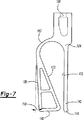
図示の実施例は、取外し(分解)作業において独特な特徴を有する。前記ウエッジ部126は、開口部170を備えることが望ましく、前記開口部は、少なくともウエッジ126内に部分的に延びており、一つの好適な実施例においては、前記ウエッジ部126を貫通する構造となる。前記ブレス部材132は、少なくとも前記ブレス部材側壁の少なくとも一方の側壁を貫通する開口部172を備えることが望ましい。前記穴170と前記穴172とは、前記端末装置が組み付けられるときに、同じ方向に面していることが望ましい。前記ウエッジ部126を(図のように)下方に引く力Fによって、前記開口部170と前記開口部172との位置ずれが生じる。前記端末装置アセンブリ20’から前記ベルト22を取り外す必要があるときには、スクリュウドライバーもしくは他のプライング(てこ)ツールを、前記開口部170と前記開口部172とに、挿入することができる。前記工具の操作により、前記ウエッジ部126を前記ソケット部124内により奥深くに(つまり、図では上方に)、押し戻すことが可能となる。この位置においては、前記レッグ部140を、前記レッグ部142に自由に近づけることができ、そのため、前記ブレス部材132を、前記突起144の上を越えてスライドさせ、前記ソケット部124から取り外すことが可能となる。取り外し時のてこの動作によって、前記ブレス部材132が、前記突起144の上に、少なくとも部分的に重なるように、前記開口部170および前記開口部172を設計することが望ましく、それにより、前記ソケット部124からの前記ブレス部材132の取り外しが容易となる。
The illustrated embodiment has unique features in the removal (disassembly) operation. The
図示の実施例においては、前記荷重支持部材22からの全ての引張り力は、前記ソケット部124にかかり、同時に、前記ウエッジ部126によって引き起こされる全ての拡張力は、前記ブレス部材132にかかる。それゆえ、この実施例では、前記引張り力と前記拡張力とを、2つの別々の成分に分離し、扱うことができる。このような構成は、前記端末部アセンブリ20’の構造的な強度を増大させる。
In the illustrated embodiment, all tensile forces from the
本発明にかかる別の利点は、前記ベルト22の破断強さを増大せしめることである。大抵の構成においては、端末部アセンブリ内において、荷重によって前記ベルト22に生じる引張応力は、通常、前記ベルト22が前記端末部のアセンブリに入っていく箇所で、最大となる。摩擦現象があるために、前記ソケット部124の内側に内挿されている前記ベルトの長さに沿って、前記ベルト22の引張応力は、低下していく。前記ベルト22に生じる応力は、引張応力と前記引張応力と直交する圧縮応力の組合せ応力であり、前記圧縮応力は、前記端末部アセンブリにより生じた楔作用の力からもたらされる。楔作用の圧力が均一分布となるときに、前記端末部アセンブリの入口部で、ミーゼス相当応力は最大となる。
Another advantage of the present invention is to increase the breaking strength of the
前記ウエッジ部および前記ソケット部のベルト係合面の構造を適切に選択することにより、本発明を用いて、前記ベルト22の引張応力がより小さくなる前記ソケット部内側に、前記最大圧力が生ずるように、楔作用の圧力を再配分することが可能となる。かかる構成は、ロープの破断荷重を増大させる。本発明は、押出成形されたウエッジ部とソケット部とを使用し、前記ウエッジ部と前記ソケット部との押し出し加工表面を最適に設計することで、前記コンポーネントの望ましい形状を得ることが経済的に実現可能となるので、付加的なコストが一切生じないのである。
By appropriately selecting the structure of the belt engaging surface of the wedge portion and the socket portion, the maximum pressure is generated inside the socket portion where the tensile stress of the
以上の記載は、単に例示的なものであり、本発明を制限しているものではない。開示された前記実施例の改良や変更が、当業者であれば明白であろうし、そして、これらの改良や変更は、本発明の範囲や趣旨から逸脱しないであろう。本発明に付与される法的な保護範囲は、付随の請求項を検討することによってのみ、決定されるものである。 The above description is illustrative only and is not intended to limit the present invention. Improvements and modifications of the disclosed embodiments will be apparent to those skilled in the art, and these improvements and modifications will not depart from the scope or spirit of the invention. The scope of legal protection given to this invention can only be determined by studying the appended claims.
Claims (11)
前記ソケット部内に少なくとも部分的に収容され、かつ細長い荷重支持部材の一部分を前記ソケット部の前記接触面との間に収容するウエッジ部と、
前記ソケット部内に前記ウエッジ部を固定し、かつ前記ウエッジ部に対してソケット部を締め付ける少なくとも1つのブレス部材と、を備え、
前記ブレス部材は、内側に接触面を備え、前記ソケット部は、このブレス部材の内側接触面と協働する接触面を外側に備え、前記細長い荷重支持部材の一部を前記ブレス部材の前記内側接触面と前記ソケット部の外側接触面との間で保持することを特徴とするエレベータシステムの細長い荷重支持部材の端部を固定する装置。Sockets with contact surfaces facing each other inside ;
A wedge portion that is at least partially housed in the socket portion and that houses a portion of the elongated load support member between the contact surface of the socket portion;
At least one breath member for fixing the wedge portion in the socket portion and tightening the socket portion with respect to the wedge portion ;
The brace member includes a contact surface on the inner side, the socket portion includes a contact surface on the outer side that cooperates with the inner contact surface of the brace member, and a part of the elongated load support member is disposed on the inner side of the brace member. An apparatus for fixing an end portion of an elongated load supporting member of an elevator system, wherein the device is held between a contact surface and an outer contact surface of the socket portion .
Applications Claiming Priority (3)
| Application Number | Priority Date | Filing Date | Title |
|---|---|---|---|
| US09/837,825 US20020154945A1 (en) | 2001-04-18 | 2001-04-18 | Elevator load bearing termination assembly with constant profile extrusion |
| US10/036,678 US6994487B2 (en) | 2001-04-18 | 2001-12-21 | Elevator load bearing termination assembly |
| PCT/US2002/011925 WO2002085772A1 (en) | 2001-04-18 | 2002-04-16 | Elevator load bearing termination assembly |
Publications (3)
| Publication Number | Publication Date |
|---|---|
| JP2004536753A JP2004536753A (en) | 2004-12-09 |
| JP2004536753A5 JP2004536753A5 (en) | 2005-08-04 |
| JP4167492B2 true JP4167492B2 (en) | 2008-10-15 |
Family
ID=26713383
Family Applications (1)
| Application Number | Title | Priority Date | Filing Date |
|---|---|---|---|
| JP2002583311A Expired - Fee Related JP4167492B2 (en) | 2001-04-18 | 2002-04-16 | Terminal assembly for elevator load support |
Country Status (6)
| Country | Link |
|---|---|
| US (1) | US6994487B2 (en) |
| EP (1) | EP1381555B1 (en) |
| JP (1) | JP4167492B2 (en) |
| CN (1) | CN1298604C (en) |
| DE (1) | DE60226590D1 (en) |
| WO (1) | WO2002085772A1 (en) |
Families Citing this family (29)
| Publication number | Priority date | Publication date | Assignee | Title |
|---|---|---|---|---|
| US6769128B1 (en) | 1995-06-07 | 2004-07-27 | United Video Properties, Inc. | Electronic television program guide schedule system and method with data feed access |
| CN1941863B (en) | 1997-07-21 | 2011-06-29 | 骏升发展(美国)有限公司 | Method for displaying target advertisement to user in electronic program guide system |
| US6898762B2 (en) | 1998-08-21 | 2005-05-24 | United Video Properties, Inc. | Client-server electronic program guide |
| ZA200506660B (en) * | 2004-09-13 | 2006-05-31 | Inventio Ag | Belt end connection for fastening a belt end in a lift installation and method for protecting and checking a belt end connection in a lift installation |
| ATE527200T1 (en) * | 2004-09-13 | 2011-10-15 | Inventio Ag | SUPPORT MEANS END CONNECTION FOR FIXING AN END OF A SUPPORT MEANS IN AN ELEVATOR SYSTEM AND METHOD FOR FIXING AN END OF A SUPPORT MEANS IN AN ELEVATOR SYSTEM |
| JP4788143B2 (en) * | 2005-01-19 | 2011-10-05 | 三菱電機株式会社 | Elevator control cable laying fixture |
| SG129351A1 (en) * | 2005-07-22 | 2007-02-26 | Inventio Ag | Lift installation with a support means end connection and a support means, and a method of fasteningan end of a support means in a lift installation |
| JP2007031148A (en) * | 2005-07-22 | 2007-02-08 | Inventio Ag | Support means end connection part for fastening end of support means in elevator device, elevator device having support means end connection part and method of fastening end of support means in elevator device |
| US20070213154A1 (en) * | 2006-03-13 | 2007-09-13 | Broyan Frederick K | Drive mechanism for non-personnel lifting device |
| BRPI0621992A2 (en) * | 2006-08-29 | 2011-12-27 | Otis Elevator Co | Socket and one socket production method |
| EP2000431A1 (en) * | 2007-06-04 | 2008-12-10 | Inventio Ag | Terminal connector and method for attaching a belt-like load carrier of a lift system |
| PE20110444A1 (en) * | 2008-06-24 | 2011-07-01 | Esco Corp | COT AND BUSHING ASSEMBLY |
| WO2010000330A1 (en) * | 2008-07-04 | 2010-01-07 | Inventio Ag | Suspension element end connection having a moldable body |
| US8096024B2 (en) * | 2008-08-13 | 2012-01-17 | Thyssenkrupp Elevator Capital Corporation | Rope termination device |
| US20100257705A1 (en) * | 2009-04-14 | 2010-10-14 | Sorin Ciobotaru | Belt clamp |
| US20100281659A1 (en) * | 2009-05-05 | 2010-11-11 | Sorin Ciobotaru | Belt clamp |
| US8375527B1 (en) | 2009-08-07 | 2013-02-19 | The Crosby Group, Inc. | Actuated wedge socket assembly |
| WO2012108872A1 (en) * | 2011-02-11 | 2012-08-16 | Otis Elevator Company | Termination assembly |
| US9347520B2 (en) | 2011-12-01 | 2016-05-24 | Gates Corporation | Flat belt clamping system and method |
| EP2925656B1 (en) * | 2012-11-29 | 2019-07-31 | Inventio AG | Lift assembly |
| CN104870356B (en) * | 2012-12-18 | 2017-06-09 | 因温特奥股份公司 | Fixing device used by the balancing component of lift facility |
| CN107108161B (en) | 2014-12-19 | 2021-05-11 | 奥的斯电梯公司 | Terminal for elevator belt |
| EP3187451A1 (en) * | 2016-01-04 | 2017-07-05 | KONE Corporation | Method for manufacturing a rope terminal equipment, method for manufacturing a rope terminal arrangement and elevator |
| US10131521B2 (en) * | 2016-10-24 | 2018-11-20 | Thyssenkrupp Elevator Ag | Belt end termination with a cone clamp |
| US11111105B2 (en) | 2017-01-26 | 2021-09-07 | Otis Elevator Company | Compliant shear layer for elevator termination |
| FI129671B (en) * | 2019-09-09 | 2022-06-30 | Konecranes Global Oy | Rope fastening arrangement of hoisting device |
| CN111437539A (en) * | 2020-05-12 | 2020-07-24 | 浙江雷云科技有限公司 | Rope optional position can connect from tensioning anticreep knot |
| ES2884274B2 (en) * | 2020-06-05 | 2022-07-27 | Barri Eduard Goula | Steel cable regulating terminal and procedure for its use |
| US11577119B2 (en) * | 2021-01-27 | 2023-02-14 | Gregory W. Williams | Modular cable machine exercise system |
Family Cites Families (15)
| Publication number | Priority date | Publication date | Assignee | Title |
|---|---|---|---|---|
| US482975A (en) * | 1892-09-20 | Grip for ropes | ||
| US1644376A (en) * | 1927-01-10 | 1927-10-04 | Haworth Jehu Frederic | Cable or wire clamp |
| GB456358A (en) | 1934-05-11 | 1936-11-09 | Gutehoffnungshuette Oberhausen | Improvements in and relating to clamps or cappings for winding ropes for miners' cages |
| US2085333A (en) * | 1936-03-13 | 1937-06-29 | Nazro H Reynolds | Rope socket |
| US2234028A (en) | 1940-04-05 | 1941-03-04 | Illinois Malleable Iron Co | Clamp |
| US4536921A (en) * | 1981-10-30 | 1985-08-27 | Geroh Gmbh, Mechanische Systeme | Cable clamp |
| DE3217885A1 (en) | 1982-05-12 | 1983-11-24 | Geroh GmbH Mechanische Systeme, 8551 Waischenfeld | Cable clamp |
| US4602891A (en) * | 1985-05-10 | 1986-07-29 | Mcbride Arlen P | Open wedge socket |
| US5243739A (en) * | 1991-09-05 | 1993-09-14 | Schmidt Don F | Two piece cable termination socket assembly |
| US5553360A (en) | 1995-05-19 | 1996-09-10 | The Crosby Group, Inc. | Extended wedge socket assembly |
| US6484368B1 (en) * | 2000-01-11 | 2002-11-26 | Otis Elevator Company | Flexible flat tension member termination device |
| US6345419B1 (en) * | 2000-01-19 | 2002-02-12 | Otis Elevator Company | Termination for flat flexible tension member |
| US6353979B1 (en) * | 2000-01-19 | 2002-03-12 | Otis Elevator Company | Termination for flat flexible tension member |
| US20020154945A1 (en) * | 2001-04-18 | 2002-10-24 | Ericson Richard J. | Elevator load bearing termination assembly with constant profile extrusion |
| US6662408B2 (en) * | 2001-09-07 | 2003-12-16 | Otis Elevator Company | Elevator load bearing termination assembly with gripping inserts |
-
2001
- 2001-12-21 US US10/036,678 patent/US6994487B2/en not_active Expired - Lifetime
-
2002
- 2002-04-16 JP JP2002583311A patent/JP4167492B2/en not_active Expired - Fee Related
- 2002-04-16 CN CNB028084578A patent/CN1298604C/en not_active Expired - Lifetime
- 2002-04-16 EP EP02728779A patent/EP1381555B1/en not_active Expired - Lifetime
- 2002-04-16 DE DE60226590T patent/DE60226590D1/en not_active Expired - Lifetime
- 2002-04-16 WO PCT/US2002/011925 patent/WO2002085772A1/en active Application Filing
Also Published As
| Publication number | Publication date |
|---|---|
| US6994487B2 (en) | 2006-02-07 |
| DE60226590D1 (en) | 2008-06-26 |
| JP2004536753A (en) | 2004-12-09 |
| EP1381555B1 (en) | 2008-05-14 |
| CN1298604C (en) | 2007-02-07 |
| CN1535239A (en) | 2004-10-06 |
| EP1381555A1 (en) | 2004-01-21 |
| US20020154944A1 (en) | 2002-10-24 |
| WO2002085772A1 (en) | 2002-10-31 |
Similar Documents
| Publication | Publication Date | Title |
|---|---|---|
| JP4167492B2 (en) | Terminal assembly for elevator load support | |
| JP6130381B2 (en) | Inter-pipe brace assembly | |
| JP5096670B2 (en) | Belt end coupling device and method for protecting belt end coupling device | |
| JP2004536753A5 (en) | ||
| US7063299B2 (en) | Suspending equipment | |
| JP2007008283A (en) | Load energy absorber | |
| JPH08232924A (en) | Expanding anchor | |
| JP2001165245A (en) | Wedge type rope clamping device | |
| US8006459B2 (en) | Shear plate | |
| JP4809797B2 (en) | Anti-sway wire connecting member and anti-sway wire connecting method using the same | |
| EP1653091A1 (en) | Self-locking threaded tubular rivet | |
| JP4669345B2 (en) | Wiring / pipe material support, support fixture | |
| US20020154945A1 (en) | Elevator load bearing termination assembly with constant profile extrusion | |
| KR101973400B1 (en) | Apparatus for Assembling Wire-rope, and Method for Assembling Wire-rope Using The Same | |
| KR101293672B1 (en) | Anchor Device | |
| JP2006292117A (en) | Belt clamp | |
| KR20190110293A (en) | Adapter and Sway Brace Fitting in use of Sway Brace Device for Building like Pipe | |
| JP5639827B2 (en) | External wall panel mounting structure | |
| KR100602871B1 (en) | structure for fixing a tie bar | |
| KR102107050B1 (en) | Seismic cable brace | |
| JPH07317721A (en) | Fixing method for terminal of cableway cable and fixng tool for it | |
| JP3565605B2 (en) | Anti-vibration device for diagonal cable | |
| HU223934B1 (en) | Hammer-block element attachment in mounting track | |
| JP2017120111A (en) | Rope body for suspension and fixation structure for duct | |
| JPH07317720A (en) | Fixing method for terminal of cableway cable and fixing tool for it |
Legal Events
| Date | Code | Title | Description |
|---|---|---|---|
| A621 | Written request for application examination |
Free format text: JAPANESE INTERMEDIATE CODE: A621 Effective date: 20050415 |
|
| A131 | Notification of reasons for refusal |
Free format text: JAPANESE INTERMEDIATE CODE: A131 Effective date: 20071211 |
|
| A521 | Written amendment |
Free format text: JAPANESE INTERMEDIATE CODE: A523 Effective date: 20080131 |
|
| TRDD | Decision of grant or rejection written | ||
| A01 | Written decision to grant a patent or to grant a registration (utility model) |
Free format text: JAPANESE INTERMEDIATE CODE: A01 Effective date: 20080729 |
|
| A01 | Written decision to grant a patent or to grant a registration (utility model) |
Free format text: JAPANESE INTERMEDIATE CODE: A01 |
|
| A61 | First payment of annual fees (during grant procedure) |
Free format text: JAPANESE INTERMEDIATE CODE: A61 Effective date: 20080801 |
|
| R150 | Certificate of patent or registration of utility model |
Free format text: JAPANESE INTERMEDIATE CODE: R150 |
|
| FPAY | Renewal fee payment (event date is renewal date of database) |
Free format text: PAYMENT UNTIL: 20110808 Year of fee payment: 3 |
|
| FPAY | Renewal fee payment (event date is renewal date of database) |
Free format text: PAYMENT UNTIL: 20110808 Year of fee payment: 3 |
|
| FPAY | Renewal fee payment (event date is renewal date of database) |
Free format text: PAYMENT UNTIL: 20120808 Year of fee payment: 4 |
|
| FPAY | Renewal fee payment (event date is renewal date of database) |
Free format text: PAYMENT UNTIL: 20130808 Year of fee payment: 5 |
|
| R250 | Receipt of annual fees |
Free format text: JAPANESE INTERMEDIATE CODE: R250 |
|
| R250 | Receipt of annual fees |
Free format text: JAPANESE INTERMEDIATE CODE: R250 |
|
| LAPS | Cancellation because of no payment of annual fees |