JP4167478B2 - Air conditioner indoor unit - Google Patents
Air conditioner indoor unit Download PDFInfo
- Publication number
- JP4167478B2 JP4167478B2 JP2002344275A JP2002344275A JP4167478B2 JP 4167478 B2 JP4167478 B2 JP 4167478B2 JP 2002344275 A JP2002344275 A JP 2002344275A JP 2002344275 A JP2002344275 A JP 2002344275A JP 4167478 B2 JP4167478 B2 JP 4167478B2
- Authority
- JP
- Japan
- Prior art keywords
- dust collection
- unit
- guide
- collection unit
- air
- Prior art date
- Legal status (The legal status is an assumption and is not a legal conclusion. Google has not performed a legal analysis and makes no representation as to the accuracy of the status listed.)
- Expired - Fee Related
Links
Images

Landscapes
- Devices For Blowing Cold Air, Devices For Blowing Warm Air, And Means For Preventing Water Condensation In Air Conditioning Units (AREA)
- Air Filters, Heat-Exchange Apparatuses, And Housings Of Air-Conditioning Units (AREA)
Description
【0001】
【発明の属する技術分野】
本発明は、いわゆる天井埋込み型の空気調和機の室内機に係り、特に、電気集塵機を備え、この電気集塵機の配置構造および取付け構造の改良に関する。
【0002】
【従来の技術】
空気調和機の室内機として、店舗などの広い空間を空調する場合には、壁面に取付けられる、いわゆる壁掛け形よりも、天井面から極めて広い範囲に亘って均一に熱交換された空気を吹出すことができ、かつ居住者が受ける圧迫感の少ない天井埋込み型とした室内機が多用される傾向にある。
【0003】
また、近時の室内機においては、電気集塵機を備え室内に浮遊する塵埃を捕捉し除去する空気清浄機能を備えることが一般的になりつつある。上記電気集塵機は、[特許公報1]にも開示されるように、天井埋込み型の室内機にも備えられている。
【0004】
【特許公報1】
特許番号 第2568717号(請求項1、図1参照)
【0005】
【発明が解決しようとする課題】
ところで、先行技術[特許公報1]のような天井埋込み型の室内機は、壁掛け型と比較して室内空気の吸込み面積が小さい。壁掛け型と同程度の集塵能力を確保するには、室内空気の流速の速い位置に電気集塵機を取付ける必要があるが、先行技術ではその点について特に配慮されていない。
【0006】
また、一般的な家屋では、天井埋込み型の室内機を取付けるべき天井裏の高さが低い。室内機の高さ寸法を低く抑えるため、熱交換器は斜めに傾斜した状態で本体内に収容する。したがって、電気集塵機は傾斜した熱交換器の空気導入側である傾斜下部側に配置せざるを得ない。
【0007】
電気集塵機の配置構成は無理のない範囲で可能となるが、その位置の設定の結果、熱交換器の熱交換作用にともなって生成されるドレン水が電気集塵機を濡らし、水漏れ事故の発生の虞れがある。
【0008】
さらに、電気集塵機のメンテナンスを行う際は、室内機本体を見上げながら電気集塵機着脱の作業を行うが、このとき誤って電気集塵機から手を滑らして頭上、もしくは床上に落してしまうことは充分考えられる。
【0009】
本発明は上記事情に着目してなされたものであり、その目的とするところは、天井埋込み型であることを前提として、電気集塵機の集塵性能の向上を図り、熱交換器から電気集塵機へのドレン水の落下を確実に阻止し、メンテナンス時の電気集塵機の脱落を確実に阻止して、安全性および信頼性の向上を図れる空気調和機の室内機を提供しようとするものである。
【0010】
【課題を解決するための手段】
上記課題を解決し目的を達成するために本発明の空気調和機の室内機は、被空調室の天井裏に取付けられる室内機本体内に、斜めに傾斜する熱交換器、熱交換器の下部に配置されるドレンパン、熱交換器の空気導入側に熱交換器と並行して配置されるドレンガイドおよび送風機等を収容し、室内機本体の下面部に取付けられて室内に露出する化粧パネルに吸込み口および吹出し口を備え、送風機の送風作用にともない吸込み口から吸込まれた室内空気をドレンガイドを介して熱交換器に導き熱交換したうえで吹出し口から室内へ吹出す空気流路を構成し、吸込み口からドレンガイドに至る空気流路の中途部で、ドレンガイドの下部側に電気集塵機を配置して空気流路に導かれる空気から塵埃を捕捉除去し、
上記電気集塵機は、左右側面それぞれに係合突起部とスライド案内突起部が前後に形成され、かつ集塵機能を備えた集塵ユニットと、左右両側に集塵ユニットを保持する保持部が形成され、この保持部の互いに対向する側面部に集塵ユニットの案内突起部がスライド挿入される案内部および、この案内部の入口部に集塵ユニットの係合突起部が挿入される係止部が形成され、保持部相互間に集塵ユニットをスライド付勢することにより着脱自在に取付けられるメインフレームと、このメインフレームに設けられ、集塵ユニットの案内突起部がメインフレームから脱離しようとした状態でこの案内突起部に当接して通過を阻止し、集塵ユニットを人為的にメインフレームから取り外す際に弾性的に変位して案内突起部の通過を許容するばね機能を備えた脱落防止部と、集塵ユニットを取付けた状態で集塵ユニット一部を押え込み抜け出を規制するユニット押えとを具備した。
【0013】
このような課題を解決する手段を採用することにより、電気集塵機の集塵性能の向上を図り、熱交換器から電気集塵機へのドレン水の落下を確実に阻止し、メンテナンス時の電気集塵機の脱落を確実に阻止して、安全性および信頼性の向上を図れる。
【0014】
【発明の実施の形態】
以下、本発明の実施の形態を図面にもとづいて説明する。
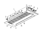
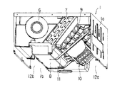
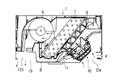
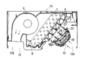
図1は本発明の一実施の形態に係る天井埋込み型の空気調和機の室内機外観を下面側から示す斜視図、図2は室内機本体1の内部構造を示す斜視図、図3は室内機本体1の内部構造を示す断面図である。
【0015】
空気調和機の室内機は、被空調室の天井板に設けられる開口部に挿入され、吊りボルト等を介して天井裏に吊持固定される室内機本体1および、この室内機本体1の下面部に取付けられ室内に露出して取付用開口部と室内機本体1側面部との間隙を遮蔽する化粧パネル2とから構成される。
【0016】
室内機本体1は、長手方向が、長手方向と直交する方向である幅方向に対して極端に長い矩形箱状に成型され、下面のみ開口し他の周面の全てが板面をなす筐体である。
【0017】
この筐体は金属薄板を板金加工したものであって、内面にはたとえば発泡スチロール材などの合成樹脂材からなる断熱材が組み込まれ、室内機本体1として断熱構造をなしている。
【0018】
室内機本体1の長手方向両側面部1aにはそれぞれ一対ずつの吊り金具3が設けられ、天井裏から吊持される吊りボルトに取付けられるようになっている。室内機本体1の一方側(図の右側)の側面部1aで、吊り金具3の近傍部位に2本の配管接続部4と1本のケーブル用パイプ5端部が突出している。
【0019】
上記配管接続部4の室内機本体1内に冷媒管が接続されていて、この冷媒管は後述する室内機本体1内の室内熱交換器7に連通する。配管接続部4には室外機から延出する冷媒渡り管が接続される。上記ケーブル用パイプ5には、室内機と室外機を電気的に接続する渡りケーブルを挿通するようになっている。
【0020】
室内機本体1の下面開口部1bは、上記化粧パネル2によって閉成される。この化粧パネル2は室内に露出し、室内機本体1側面部と天井板に設けられる取付け用開口部との隙間を遮蔽する。
【0021】
上記室内機本体1の幅方向一側部に送風機6が配置され、この送風機6の空気吸込み側と対向して室内熱交換器7が室内機本体1の下端部から上端部に亘って斜めに傾斜して配置される。
【0022】
上記室内熱交換器7の上端面は室内機本体1上面部に略密着状態にあり、下端部はドレンパン8に嵌め込まれる。室内熱交換器7の空気導入側には、ドレンガイド9が室内熱交換器7と対向する傾斜状態で配置される。
【0023】
上記ドレンガイド9のさらに空気導入側には、ここを通過する空気に含まれる塵埃を捕捉除去する電気集塵機10が配置される。この電気集塵機10は、一端部が室内機本体1の側面部1aに取付け固定され、他端部がドレンパン8下面部に取付け固定される集塵機支持ベース11に支持される。
【0024】
上記電気集塵機10は、集塵機内部を通過する空気が空気導入側から導かれる空気の流れに沿うように斜めに傾斜して設定される。
室内機本体1の下面開口部1bは、幅方向の略中央部を長手方向に亘って設けられる上記ドレンパン8によって仕切られ、上記電気集塵機10側の開口部を吸込み部12a、他方側の開口部を吹出し部12bとして構成する。
【0025】
上記吸込み部12aと対向する化粧パネル2部位には吸込み口13が開口され、吸込グリル14が着脱自在に取付けられる。上記吹出し部12bと対向する化粧パネル2部位には吹出し口15が開口され、室内の広い範囲に亘って均一に熱交換された空気を吹出し案内するためのルーバー16が取付けられる。
【0026】
このように構成された天井埋込型の空気調和機の室内機において、送風機6が駆動されると室内空気が吸込みグリル14と吸込み口13を介して室内機本体1内に吸引される。
【0027】
室内空気は電気集塵機10を通過し、空気に含まれる細かな塵埃が除去捕捉される。さらに、ドレンガイド9を通過して室内熱交換器7に導かれ、ここで熱交換がなされたあと、送風機6を介して吹出口15から室内へ吹出される空気流路Kが構成される。
【0028】
上記電気集塵機10は、集塵機内部を通過する空気が空気流路Kに導かれる空気の流れに沿う方向に向けられているので、電気集塵機10の配置による通風抵抗が最小限に抑制され、電気集塵機10が効率よく集塵できて、集塵性能の向上を得られる。
【0029】
冷房運転時において、室内熱交換器7には熱交換作用にともなってドレン水が生成される。熱交換器7表面を流下したドレン水は、直接ドレンパン8に受けられるが、熱交換器7表面の途中から重力方向に滴下する一部のドレン水は、熱交換器下面に対向して設置されるドレンガイド9によって受けられる。
【0030】
ドレンガイド9が受けたドレン水はドレンパン8に導かれ、ドレンパン8内のドレン水と合流し、ドレンポンプなどの排水手段により室外へ排水される。ドレンガイド9は室内空気の流通を阻害せず、しかも室内熱交換器7から滴下するドレン水を電気集塵機10に水漏れすることがなく確実に受ける。
【0031】
つぎに、上記電気集塵機10および電気集塵機10に対する支持構成について、図4〜図9にもとづいて詳述する。
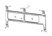
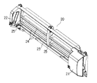
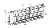
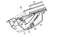
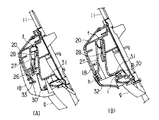
図4は集塵機支持ベース11の斜視図、図5はメインフレーム20の表面側斜視図、図6はメインフレームの裏面側斜視図、図7はメインフレーム一部の斜視図、図8(A)(B)は集塵ユニット18の取付け構造を説明する図、図9(A)(B)は集塵ユニットの押え構造を説明する斜視図である。
【0032】
上記電気集塵機10を支持する集塵機支持ベース11は、略中央の桟部aを境にして左右に矩形状の開口部bを備えている。上端の左右両側と中央部に室内機本体1の側面部1aに取付け固定される係止片cが一体に突設され、下端の左右両側にドレンパン8の底面部に取付け固定される係止片dが一体に突設される。
【0033】
上記集塵機支持ベース11は、上下両端の係止片c、dを室内機本体側面部1aとドレンパン8とに取付け固定することにより、電気集塵機10を支持する支持機構として剛性の増大化を図れる。
【0034】
一方、上記電気集塵機10は、集塵ユニット18とメインフレーム20とから構成されている。
上記メインフレーム20は、その左右方向両側に、前方に突出する集塵ユニット保持部21,22が設けられる。これら集塵ユニット保持部21,22相互間に形成される凹状部分は、上記集塵ユニット18が着脱自在に取付けられる収納部23である。
【0035】
上記集塵ユニット18は、内部空間を空気が通過する荷電側電極と集塵側電極とから構成され、荷電側電極は空気中の塵埃に電荷を与え、そのあと集塵側電極において電荷を与えられた塵埃を引きつけ、これら塵埃を捕捉し除去する集塵機能を備えている。
【0036】
上記メインフレーム20の収納部23は、可能な限り通風抵抗を抑制した状態で空気を流通させ、かつ室内熱交換器7から滴下したドレン水がドレンガイド9に落下して跳ね、互いの隙間を介して集塵ユニット18側に侵入するのを遮る部材を備えている。
【0037】
上記侵入防止部材についてなお説明すれば、上記収納部23は、上下方向に所定間隔を存して並行して設けられた水受板24と、これら水受板24の略中央部と左右両側部で、かつ水受板24とは直交する縦方向に設けられる複数本の仕切枠25とからなる。
【0038】
これら水受板24と仕切枠25との間の空間部を、空気が流通する。水受板24は室内熱交換器7とドレンガイド9の隙間を介して飛び散ったドレン水を受けるよう先端がL字状に折曲する平面部より構成される。
【0039】
この水受板24で受けるドレン水は非常に僅かな量であり、送風機6の運転中に水受板24表面を通過する空気により蒸発乾燥してしまうため、特に水受板24に付着したドレンを排水処理する構成を必要としない。
【0040】
上記水受板24は風向に沿って並行に設けられ、さらに上記L字状に形成される部分の端縁は付着する水滴が集塵ユニット18側に落ちないよう上下方向にラップして設けられる。
【0041】
このようにして、上記電気集塵機10は斜めに傾斜する室内熱交換器7の下部側にドレンガイド9を介して配置されているが、電気集塵機10を構成する集塵ユニット18はメインフレーム20の収納部23を介してドレンガイド9に対向するよう構成される。
【0042】
したがって、室内熱交換器7からドレン水がドレンガイド9に滴下し、一部のドレン水が飛び跳ねて収納部23側へ滴下するようなことがあっても、メインフレーム20の収納部23の裏面側に設けられる水受板24が受けて集塵ユニット18が水濡れすることがなく、安全性が確保されている。
【0043】
上記集塵ユニット18は、両側面に、手前側に突出する係合突起部30と、この係合突起部30の所定長さだけ奥方に位置するスライド案内突起部28とが設けられている。
【0044】
上記係合突起部30は断面が略C形状で外面が弾性を有している。また、上記スライド案内突起部28は、奥方に延び先端側に膨張部分を備えた板形形状を有している。
【0045】
メインフレーム20における集塵ユニット保持部21,22の側面部に、集塵ユニット18のスライド案内突起部28を挿入できるよう上方向に延びる溝形状の案内部27と、この案内部の入口部に集塵ユニット18の係合突起部30を挿入嵌合できるよう斜め方向に延びる溝形状の係止部31が設けられる。
【0046】
上記案内部27の下部側開口端には、集塵ユニット18に対する脱落防止用の爪部(脱落防止部)26が設けられる。この爪部26は案内部27の下側スライド面から対向面側に突出していて、爪部26のみが弾性的に変形可能な構成になっている。
【0047】
集塵ユニット18をメインフレーム20に取付けるには、メインフレーム20の下端部から集塵ユニット18を上方へスライド付勢する。特に、図8(A)に示すように、集塵ユニット18のスライド案内突起部28は案内部27の開口端から内部に挿入される。
【0048】
スライド案内突起部28上端が案内部27の上端閉成部fに当接するまで集塵ユニット18を押し上げるのだが、途中で誤って集塵ユニット18から手を離すようなことがあっても、案内突起部28がメインフレーム20の爪部26に当接し、集塵ユニット18の自由落下を防ぎ安全性を確保する。
【0049】
たとえばメンテナンス時など、必要に応じて集塵ユニット18をメインフレーム20から取外す際には、図8(A)の状態から集塵ユニット18の把手gを持って引き降ろす。このとき、構成上、スライド案内突起部28が脱落防止用の爪部26に当接する。
【0050】
上述したように、上記脱落防止用の爪部26はばね機能を有しているので、集塵ユニット18を強めに引き下げれば爪部26が弾性変形してスライド案内突起部28の通過を許容し、集塵ユニット18の取外しが支障なく行える。
【0051】
図8(B)は、メインフレーム20に集塵ユニット18を取付け完了した状態を示している。すなわち、スライド案内突起部28が案内部27の上端閉成部fに当接するまで集塵ユニット18を上方に押し上げスライドさせたあと、集塵ユニット18をメインフレーム20に密着するよう押し当てる。
【0052】
この状態で、集塵ユニット18に設けられる係合突起部30がメインフレーム20に設けられる係止部31内に挿入嵌合し、メインフレーム20における集塵ユニット18の支持を確実なものとしている。
【0053】
一方側の保持部21前面に、ユニット押え32が取付けられている。このユニット押え32は、上端に形成される軸部hが保持部21前面に設けられる軸部受け33に回動自在に嵌め込まれて回動レバー構造をなしている。
【0054】
上記ユニット押え32は、その裏面側に三角状に突出する押え部iが設けられている。集塵ユニット18をメインフレーム20に取付けたあと、ユニット押え32を回動操作して保持部21前面に沿わせると、押え部iが係合突起部30に当接する。
【0055】
すなわち、ユニット押え32は係合突起部30をメインフレーム20の係止部31に強制的に押し付けて、集塵ユニット18の位置ずれを確実に規制する。集塵ユニット18を着脱する際には、ユニット押え32が邪魔にならないように上方へ回動変位して集塵ユニット18の作業スペースから外す。
【0056】
上記ユニット押え32の軸部hはメインフレーム20の軸部受け33に仮掛け固定されていて、集塵ユニット18の装着の際は軸部hを手で軽く押し付ければ掛合状態になる。そして、把手gの下部自由端を引き上れば仮掛け固定は解除され自由に回動操作できる。
【0057】
ユニット押え32の軸部hを軸部受け33に挿入して取付けられるようになっているので、強い力が作用してもユニット押え32とメインフレーム20の双方が壊れることがなく、また容易に取付けることが可能である。
【0058】
このようにして、メンテナンス時など集塵ユニット18をメインフレーム20に着脱自在に取付け、かつ集塵ユニット18のメインフレーム20に対する脱落防止構造を備えたので、より安全性が向上する。
【0059】
上記電気集塵機10の支持構造を以下に述べるように設定すれば、より集塵効率の向上を図れる。
【0060】
図10は異なる実施の形態の室内機本体1Aの断面図であり、電気集塵機10を支持する集塵機支持ベース11を省略して示している。先に説明した構成部品と同一部品については同番号を付して新たな説明を省略する。
【0061】
電気集塵機10の取付け位置と傾き姿勢は先に説明したものと全く同一である。そして、電気集塵機10は先に説明したように、集塵ユニット18とメインフレーム20とから構成されていることも同様である。
【0062】
必要な特徴として、メインフレーム20を構成する収納部23と、上記室内熱交換器7と並行して配置されるドレンガイド9は、上記空気流路Kに沿って互いに対向して設けられる枠部と、互いに連通する開口部を備えている。
【0063】
具体的には、図に一点鎖線で示すように、メインフレーム20の収納部23形状は、室内熱交換器7の吸込み面を垂直に見たとき、ドレンガイド9の水受板24と重なるように配置される。これにより、電気集塵機10を流れる空気の風量損失を最小限に抑えることができる。
【0065】
さらに、本発明は上述の実施の形態に限定されるものではなく、本発明の要旨を逸脱しない範囲で種々変形実施可能であるのは勿論である。
【0066】
【発明の効果】
以上説明したように本発明によれば、天井埋込み型であることを前提として、電気集塵機の集塵性能の向上を図り、熱交換器から電気集塵機へのドレン水の落下を確実に阻止し、メンテナンス時の電気集塵機の脱落を確実に阻止して、安全性および信頼性の向上を得るなどの効果を奏する。
【図面の簡単な説明】
【図1】本発明の一実施の形態に係る天井埋込み型の空気調和機の室内機を下面側から示す斜視図。
【図2】同実施の形態に係る、室内機本体の斜視図。
【図3】同実施の形態に係る、室内機本体の断面図。
【図4】同実施の形態に係る、集塵機支持ベースの斜視図。
【図5】同実施の形態に係る、メインフレームを表面側から見た斜視図。
【図6】同実施の形態に係る、メインフレームを裏面側から見た斜視図。
【図7】同実施の形態に係る、メインフレーム保持部の斜視図。
【図8】同実施の形態に係る、集塵ユニットのメインフレームに対する取付けを説明する断面図。
【図9】同実施の形態に係る、集塵ユニットに対するユニット押えの作用を説明する斜視図。
【図10】異なる実施の形態に係る、室内機本体の断面図。
【符号の説明】
7…室内熱交換器、
8…ドレンパン、
9…ドレンガイド、
1…室内機本体、
2…化粧パネル、
K…空気流路、
11…集塵機支持ベース、
10…電気集塵機、
18…集塵ユニット、
20…メインフレーム、
26…脱落防止用爪部、
32…ユニット押え。[0001]
BACKGROUND OF THE INVENTION
The present invention relates to an indoor unit of a so-called ceiling-embedded air conditioner, and more particularly to an improvement in the arrangement and mounting structure of the electric dust collector, which includes an electric dust collector.
[0002]
[Prior art]
When air-conditioning a large space such as a store as an indoor unit of an air conditioner, air that has been heat-exchanged uniformly over a very wide area from the ceiling surface is blown out rather than a so-called wall-mounted type that is attached to a wall surface. However, there is a tendency to use a ceiling-embedded indoor unit that can be used by a resident and has little feeling of pressure.
[0003]
In recent indoor units, it is becoming common to provide an air cleaning function that includes an electric dust collector and captures and removes dust floating in the room. The electrostatic precipitator is also provided in a ceiling-embedded indoor unit as disclosed in [Patent Publication 1].
[0004]
[Patent Publication 1]
Patent No. 2568717 (refer to claim 1, FIG. 1)
[0005]
[Problems to be solved by the invention]
Incidentally, the ceiling-embedded indoor unit as in the prior art [Patent Publication 1] has a smaller indoor air suction area than the wall-mounted type. In order to secure the same level of dust collection capability as that of the wall-mounted type, it is necessary to install an electric dust collector at a position where the flow rate of indoor air is fast, but this is not particularly considered in the prior art.
[0006]
Moreover, in a general house, the height of the ceiling behind which a ceiling embedded type indoor unit should be attached is low. In order to keep the height dimension of the indoor unit low, the heat exchanger is accommodated in the main body in an inclined state. Therefore, the electrostatic precipitator must be disposed on the inclined lower side, which is the air introduction side of the inclined heat exchanger.
[0007]
Although it is possible to arrange the electrostatic precipitator within a reasonable range, as a result of its position setting, the drain water generated by the heat exchange action of the heat exchanger wets the electrostatic precipitator, causing the occurrence of a water leak accident. There is a fear.
[0008]
Furthermore, when performing maintenance of the electrostatic precipitator, the electric precipitator is attached / detached while looking up at the indoor unit body. At this time, it is fully possible that the hand will accidentally slip from the electrostatic precipitator and drop it on the head or floor. .
[0009]
The present invention has been made paying attention to the above circumstances, and the purpose of the present invention is to improve the dust collection performance of the electric dust collector on the premise that it is a ceiling-embedded type, and from the heat exchanger to the electric dust collector. It is an object of the present invention to provide an indoor unit of an air conditioner that can reliably prevent the drain water from falling and prevent the electric dust collector from falling off during maintenance, thereby improving safety and reliability.
[0010]
[Means for Solving the Problems]
In order to solve the above-described problems and achieve the object, the indoor unit of the air conditioner of the present invention includes a heat exchanger that is inclined obliquely in the indoor unit main body that is attached to the back of the ceiling of the air-conditioned room, and a lower part of the heat exchanger. A drain pan, a drain guide arranged in parallel with the heat exchanger, a blower, etc. are accommodated on the air introduction side of the heat exchanger, and attached to the lower surface of the indoor unit main body to be exposed to the interior of the room Constructs an air flow path that is equipped with a suction port and a blow-out port and directs the indoor air sucked from the suction port to the heat exchanger via the drain guide in accordance with the blowing action of the blower, and then heat-exchanges it from the blow-out port to the room In the middle of the air flow path from the suction port to the drain guide, an electric dust collector is arranged on the lower side of the drain guide to capture and remove dust from the air guided to the air flow path.
In the electric dust collector, an engaging projection and a slide guide projection are formed on the left and right sides, respectively, and a dust collection unit having a dust collection function and a holding unit for holding the dust collection unit on the left and right sides are formed. A guide portion in which the guide projection portion of the dust collection unit is slid and inserted in the side portions facing each other of the holding portion, and a locking portion in which the engagement projection portion of the dust collection unit is inserted in the inlet portion of the guide portion are formed. A main frame that is detachably mounted by slidably biasing the dust collection unit between the holding parts, and a state in which the guide projection of the dust collection unit is about to be detached from the main frame. A spring function that prevents the passage of the guide protrusion by allowing it to elastically displace when the dust collection unit is artificially removed from the main frame. A disengagement prevention part provided with was and a unit pressing for regulating the exit the hold-down part dust collecting unit in a state of mounting the dust collecting unit.
[0013]
By adopting means to solve these problems, the dust collection performance of the electrostatic precipitator is improved, the drain water from the heat exchanger to the electrostatic precipitator is reliably prevented, and the electrostatic precipitator falls off during maintenance. Can be reliably prevented, and safety and reliability can be improved.
[0014]
DETAILED DESCRIPTION OF THE INVENTION
Hereinafter, embodiments of the present invention will be described with reference to the drawings.
FIG. 1 is a perspective view showing an external appearance of an indoor unit of a ceiling-embedded air conditioner according to an embodiment of the present invention, FIG. 2 is a perspective view showing an internal structure of the indoor unit body 1, and FIG. It is sectional drawing which shows the internal structure of the machine main body.
[0015]
The indoor unit of the air conditioner is inserted into an opening provided in the ceiling plate of the air-conditioned room, and is suspended and fixed to the back of the ceiling via a suspension bolt or the like, and the lower surface of the indoor unit main body 1 And a decorative panel 2 that is exposed to the room and shields the gap between the mounting opening and the side surface of the indoor unit body 1.
[0016]
The indoor unit main body 1 is formed in a rectangular box shape in which the longitudinal direction is extremely long with respect to the width direction orthogonal to the longitudinal direction, and only the lower surface is opened and all other peripheral surfaces form a plate surface. It is.
[0017]
This casing is obtained by processing a thin metal plate into a sheet metal, and a heat insulating material made of a synthetic resin material such as a foamed polystyrene material is incorporated on the inner surface thereof to form a heat insulating structure as the indoor unit main body 1.
[0018]
A pair of suspension fittings 3 are provided on both side surfaces 1a in the longitudinal direction of the indoor unit body 1, and are attached to suspension bolts suspended from the ceiling. On one side (right side in the figure) of the indoor unit main body 1, two pipe connection portions 4 and one end portion of one cable pipe 5 project from the vicinity of the suspension fitting 3.
[0019]
A refrigerant pipe is connected in the indoor unit main body 1 of the pipe connection portion 4, and the refrigerant pipe communicates with an
[0020]
The lower surface opening 1 b of the indoor unit body 1 is closed by the decorative panel 2. This decorative panel 2 is exposed indoors and shields the gap between the side surface of the indoor unit body 1 and the mounting opening provided on the ceiling plate.
[0021]
A
[0022]
The upper end surface of the
[0023]
On the further air introduction side of the
[0024]
The
The lower surface opening 1b of the indoor unit main body 1 is partitioned by the
[0025]
A
[0026]
In the indoor unit of the ceiling-embedded air conditioner configured as described above, when the
[0027]
The room air passes through the
[0028]
Since the
[0029]
During the cooling operation, drain water is generated in the
[0030]
The drain water received by the
[0031]
Next, the
4 is a perspective view of the dust collector support base 11, FIG. 5 is a front side perspective view of the
[0032]
The dust collector support base 11 that supports the
[0033]
The dust collector support base 11 can increase rigidity as a support mechanism for supporting the
[0034]
On the other hand, the
The
[0035]
The
[0036]
The
[0037]
The intrusion prevention member will be further described. The
[0038]
Air circulates through the space between the
[0039]
The drain water received by the
[0040]
The
[0041]
In this way, the
[0042]
Therefore, even if the drain water drops from the
[0043]
The
[0044]
The engaging
[0045]
A groove-shaped
[0046]
A claw portion (drop-off prevention portion) 26 for preventing the
[0047]
In order to attach the
[0048]
The
[0049]
For example, when the
[0050]
As described above, the
[0051]
FIG. 8B shows a state in which the
[0052]
In this state, the engaging
[0053]
A
[0054]
The
[0055]
In other words, the
[0056]
The shaft portion h of the
[0057]
Since the shaft portion h of the
[0058]
In this way, the
[0059]
If the support structure of the
[0060]
FIG. 10 is a cross-sectional view of an indoor unit main body 1A according to a different embodiment, in which a dust collector support base 11 that supports the
[0061]
The mounting position and inclination posture of the
[0062]
As a necessary feature, the
[0063]
Specifically, as indicated by a dashed line in the figure, the shape of the
[0065]
Furthermore, the present invention is not limited to the above-described embodiment, and various modifications can be made without departing from the scope of the present invention.
[0066]
【The invention's effect】
As described above, according to the present invention, on the assumption that it is a ceiling-embedded type, the dust collection performance of the electric dust collector is improved, and the fall of drain water from the heat exchanger to the electric dust collector is reliably prevented, There is an effect that the electric dust collector is prevented from dropping off during maintenance, and safety and reliability are improved.
[Brief description of the drawings]
FIG. 1 is a perspective view showing an indoor unit of a ceiling-embedded air conditioner according to an embodiment of the present invention from the lower surface side.
FIG. 2 is a perspective view of the indoor unit main body according to the embodiment.
FIG. 3 is a cross-sectional view of the indoor unit main body according to the embodiment.
FIG. 4 is a perspective view of a dust collector support base according to the embodiment.
FIG. 5 is a perspective view of the main frame as viewed from the front side according to the embodiment;
FIG. 6 is a perspective view of the main frame as viewed from the back side according to the embodiment.
FIG. 7 is a perspective view of a main frame holding unit according to the embodiment.
FIG. 8 is a cross-sectional view illustrating attachment of the dust collection unit to the main frame according to the embodiment.
FIG. 9 is a perspective view for explaining the operation of the unit presser with respect to the dust collection unit according to the embodiment.
FIG. 10 is a cross-sectional view of an indoor unit body according to a different embodiment.
[Explanation of symbols]
7 ... Indoor heat exchanger,
8… Drain pan,
9 ... Drain guide,
1 ... indoor unit body,
2 ... makeup panel,
K: Air flow path,
11 ... Dust collector support base,
10 ... electric dust collector,
18 ... Dust collection unit,
20 ... mainframe,
26. Claw portion for preventing falling off,
32 ... Unit presser.
Claims (1)
吸込み口および吹出し口を備え、上記室内機本体の下面部に取付けられて室内に露出する化粧パネルと、
上記送風機の送風作用に伴い、上記吸込み口から吸込まれた室内空気をドレンガイドを介して熱交換器に導き熱交換したうえで上記吹出し口から室内へ吹出すよう構成される空気流路と、
上記吸込み口からドレンガイドに至る上記空気流路の中途部で、ドレンガイドの下部側に配置され、空気流路に導かれる空気から塵埃を捕捉除去する電気集塵機とを具備し、
上記電気集塵機は、
左右側面それぞれに係合突起部とスライド案内突起部が前後に形成され、かつ集塵機能を備えた集塵ユニットと、
左右両側に上記集塵ユニットを保持する保持部が形成され、この保持部の互いに対向する側面部に、集塵ユニットの案内突起部がスライド挿入される案内部および、この案内部の入口部に集塵ユニットの係合突起部が挿入される係止部が形成され、上記保持部相互間に上記集塵ユニットをスライド付勢することにより着脱自在に取付けられるメインフレームと、
このメインフレームに設けられ、集塵ユニットの案内突起部がメインフレームから脱離しようとした状態でこの案内突起部に当接して通過を阻止し、集塵ユニットを人為的にメインフレームから取り外す際に弾性的に変位して案内突起部の通過を許容するばね機能を備えた脱落防止部と、
上記集塵ユニットを取付けた状態で集塵ユニット一部を押え込み抜け出を規制するユニット押えとを備えたことを特徴とする空気調和機の室内機。Accommodates an obliquely inclined heat exchanger, a drain pan disposed under the heat exchanger, a drain guide disposed in parallel with the heat exchanger on the air introduction side of the heat exchanger, a blower, and the like. An indoor unit body mounted on the ceiling of the room,
A decorative panel that includes a suction port and a blowout port, is attached to the lower surface of the indoor unit body and is exposed to the room;
With the air blowing action of the blower, the air flow path configured to blow the indoor air sucked from the suction port to the heat exchanger through the drain guide and then to heat the indoor air, and to blow out from the blow outlet to the room,
In the middle of the air flow path from the suction port to the drain guide, it is disposed on the lower side of the drain guide, and includes an electric dust collector that captures and removes dust from the air guided to the air flow path,
The above electric dust collector
A dust collection unit having an engagement projection and a slide guide projection formed on the left and right sides, respectively, and having a dust collection function;
A holding portion for holding the dust collection unit is formed on both the left and right sides, and a guide portion in which the guide projection of the dust collection unit is slid and inserted into a side portion facing each other of the holding portion, and an entrance portion of the guide portion. A main frame that is formed with a locking portion into which an engaging protrusion of the dust collecting unit is inserted, and is detachably attached by slidably biasing the dust collecting unit between the holding portions,
When the dust collection unit is artificially removed from the main frame, the dust collection unit is placed on the main frame and the guide projection of the dust collection unit is about to be detached from the main frame to abut against the guide projection to prevent passage. A drop-off preventing portion having a spring function that is elastically displaced to allow passage of the guide protrusion,
An indoor unit for an air conditioner, comprising: a unit presser that presses a part of the dust collection unit and restricts it from being pulled out while the dust collection unit is attached.
Priority Applications (1)
| Application Number | Priority Date | Filing Date | Title |
|---|---|---|---|
| JP2002344275A JP4167478B2 (en) | 2002-11-27 | 2002-11-27 | Air conditioner indoor unit |
Applications Claiming Priority (1)
| Application Number | Priority Date | Filing Date | Title |
|---|---|---|---|
| JP2002344275A JP4167478B2 (en) | 2002-11-27 | 2002-11-27 | Air conditioner indoor unit |
Publications (2)
| Publication Number | Publication Date |
|---|---|
| JP2004177008A JP2004177008A (en) | 2004-06-24 |
| JP4167478B2 true JP4167478B2 (en) | 2008-10-15 |
Family
ID=32705814
Family Applications (1)
| Application Number | Title | Priority Date | Filing Date |
|---|---|---|---|
| JP2002344275A Expired - Fee Related JP4167478B2 (en) | 2002-11-27 | 2002-11-27 | Air conditioner indoor unit |
Country Status (1)
| Country | Link |
|---|---|
| JP (1) | JP4167478B2 (en) |
Families Citing this family (2)
| Publication number | Priority date | Publication date | Assignee | Title |
|---|---|---|---|---|
| JP4527659B2 (en) * | 2005-12-28 | 2010-08-18 | 三菱電機株式会社 | Air conditioner |
| EP2682683B1 (en) * | 2011-10-21 | 2019-06-05 | Mitsubishi Electric Corporation | Air conditioning apparatus |
-
2002
- 2002-11-27 JP JP2002344275A patent/JP4167478B2/en not_active Expired - Fee Related
Also Published As
| Publication number | Publication date |
|---|---|
| JP2004177008A (en) | 2004-06-24 |
Similar Documents
| Publication | Publication Date | Title |
|---|---|---|
| JP4490475B2 (en) | Air conditioner indoor unit | |
| CA2279464C (en) | Air filter inlet and positioning guide for an air conditioner | |
| JP5148522B2 (en) | Air conditioner indoor unit | |
| KR101417050B1 (en) | Indoor unit of air conditioner | |
| US6223547B1 (en) | Air filter guides for an air conditioner | |
| JP4167478B2 (en) | Air conditioner indoor unit | |
| JP2007271170A (en) | Air conditioner | |
| JP6160156B2 (en) | Air conditioning indoor unit | |
| KR100642365B1 (en) | Indoor unit of duct type air conditioner | |
| JPH1068534A (en) | Air conditioner | |
| CN214841191U (en) | Air conditioner indoor unit and air conditioner | |
| JP3075017B2 (en) | Ceiling-mounted air conditioner | |
| KR100548985B1 (en) | Air conditioner with rotating filter structure of air filter | |
| KR101259800B1 (en) | Indoor unit of air conditioner | |
| JP3327504B2 (en) | Air conditioner | |
| KR20070066393A (en) | Housing of indoor unit of ceiling duct type air conditioner | |
| KR200173447Y1 (en) | Spacer fixing apparatus of indoor unit for a wall tapest ried type air conditioner | |
| CN215062401U (en) | Humidifiers and Air Conditioning Systems | |
| KR101273658B1 (en) | Ceiling type air-conditioner having air guide structure | |
| KR101428677B1 (en) | Air conditioner | |
| KR200146110Y1 (en) | Front panel and back panel coupling device of indoor unit for wall-mounted air conditioner | |
| KR20090022104A (en) | Air conditioner | |
| CN107218670B (en) | Cooling fan | |
| KR100371851B1 (en) | Ceiling type of air conditioner | |
| KR200162658Y1 (en) | Motor wire fixing device of wall type airconditioner indoor device |
Legal Events
| Date | Code | Title | Description |
|---|---|---|---|
| A621 | Written request for application examination |
Free format text: JAPANESE INTERMEDIATE CODE: A621 Effective date: 20050907 |
|
| A977 | Report on retrieval |
Free format text: JAPANESE INTERMEDIATE CODE: A971007 Effective date: 20080414 |
|
| A131 | Notification of reasons for refusal |
Free format text: JAPANESE INTERMEDIATE CODE: A131 Effective date: 20080422 |
|
| A711 | Notification of change in applicant |
Free format text: JAPANESE INTERMEDIATE CODE: A712 Effective date: 20080528 |
|
| A521 | Request for written amendment filed |
Free format text: JAPANESE INTERMEDIATE CODE: A523 Effective date: 20080618 |
|
| TRDD | Decision of grant or rejection written | ||
| A01 | Written decision to grant a patent or to grant a registration (utility model) |
Free format text: JAPANESE INTERMEDIATE CODE: A01 Effective date: 20080729 |
|
| A01 | Written decision to grant a patent or to grant a registration (utility model) |
Free format text: JAPANESE INTERMEDIATE CODE: A01 |
|
| A61 | First payment of annual fees (during grant procedure) |
Free format text: JAPANESE INTERMEDIATE CODE: A61 Effective date: 20080801 |
|
| R150 | Certificate of patent or registration of utility model |
Free format text: JAPANESE INTERMEDIATE CODE: R150 |
|
| FPAY | Renewal fee payment (event date is renewal date of database) |
Free format text: PAYMENT UNTIL: 20110808 Year of fee payment: 3 |
|
| FPAY | Renewal fee payment (event date is renewal date of database) |
Free format text: PAYMENT UNTIL: 20110808 Year of fee payment: 3 |
|
| FPAY | Renewal fee payment (event date is renewal date of database) |
Free format text: PAYMENT UNTIL: 20120808 Year of fee payment: 4 |
|
| FPAY | Renewal fee payment (event date is renewal date of database) |
Free format text: PAYMENT UNTIL: 20120808 Year of fee payment: 4 |
|
| FPAY | Renewal fee payment (event date is renewal date of database) |
Free format text: PAYMENT UNTIL: 20130808 Year of fee payment: 5 |
|
| LAPS | Cancellation because of no payment of annual fees |