JP4164352B2 - Packet transfer device capable of accommodating mobile terminals - Google Patents
Packet transfer device capable of accommodating mobile terminals Download PDFInfo
- Publication number
- JP4164352B2 JP4164352B2 JP2002357810A JP2002357810A JP4164352B2 JP 4164352 B2 JP4164352 B2 JP 4164352B2 JP 2002357810 A JP2002357810 A JP 2002357810A JP 2002357810 A JP2002357810 A JP 2002357810A JP 4164352 B2 JP4164352 B2 JP 4164352B2
- Authority
- JP
- Japan
- Prior art keywords
- terminal
- segment
- address
- packet transfer
- mac
- Prior art date
- Legal status (The legal status is an assumption and is not a legal conclusion. Google has not performed a legal analysis and makes no representation as to the accuracy of the status listed.)
- Expired - Fee Related
Links
Images


Classifications
-
- H—ELECTRICITY
- H04—ELECTRIC COMMUNICATION TECHNIQUE
- H04L—TRANSMISSION OF DIGITAL INFORMATION, e.g. TELEGRAPHIC COMMUNICATION
- H04L45/00—Routing or path finding of packets in data switching networks
- H04L45/54—Organization of routing tables
-
- H—ELECTRICITY
- H04—ELECTRIC COMMUNICATION TECHNIQUE
- H04L—TRANSMISSION OF DIGITAL INFORMATION, e.g. TELEGRAPHIC COMMUNICATION
- H04L12/00—Data switching networks
- H04L12/02—Details
- H04L12/16—Arrangements for providing special services to substations
- H04L12/18—Arrangements for providing special services to substations for broadcast or conference, e.g. multicast
- H04L12/1854—Arrangements for providing special services to substations for broadcast or conference, e.g. multicast with non-centralised forwarding system, e.g. chaincast
-
- H—ELECTRICITY
- H04—ELECTRIC COMMUNICATION TECHNIQUE
- H04L—TRANSMISSION OF DIGITAL INFORMATION, e.g. TELEGRAPHIC COMMUNICATION
- H04L45/00—Routing or path finding of packets in data switching networks
- H04L45/02—Topology update or discovery
- H04L45/04—Interdomain routing, e.g. hierarchical routing
-
- H—ELECTRICITY
- H04—ELECTRIC COMMUNICATION TECHNIQUE
- H04L—TRANSMISSION OF DIGITAL INFORMATION, e.g. TELEGRAPHIC COMMUNICATION
- H04L45/00—Routing or path finding of packets in data switching networks
- H04L45/16—Multipoint routing
-
- H—ELECTRICITY
- H04—ELECTRIC COMMUNICATION TECHNIQUE
- H04L—TRANSMISSION OF DIGITAL INFORMATION, e.g. TELEGRAPHIC COMMUNICATION
- H04L12/00—Data switching networks
- H04L12/02—Details
- H04L12/16—Arrangements for providing special services to substations
- H04L12/18—Arrangements for providing special services to substations for broadcast or conference, e.g. multicast
- H04L12/185—Arrangements for providing special services to substations for broadcast or conference, e.g. multicast with management of multicast group membership
Landscapes
- Engineering & Computer Science (AREA)
- Computer Networks & Wireless Communication (AREA)
- Signal Processing (AREA)
- Data Exchanges In Wide-Area Networks (AREA)
- Small-Scale Networks (AREA)
Description
【0001】
【発明の属する技術分野】
本発明は、パケット転送装置に関し、更に詳しくは、セグメント間で接続通信端末の移動を許容する複数のブロードキャストセグメントを接続するパケット転送装置に関する。
【0002】
【従来の技術】
IPネットワークでは、例えば、イーサネット(登録商標)などで構築される複数のブロードキャストセグメントが、L3スイッチまたはルータと呼ばれるパケット転送装置によって相互接続される。この場合、ブロードキャストセグメントは、一般にサブネットワークと呼ばれるネットワーク単位に対応している。
【0003】
各サブネットワークのアドレスは、例えば、「192.168.0.0/24」のように表記される。ここで、数値列「192.168.0.0」は、32ビットのアドレス部の値を表しており、アドレスビットの値がバイト単位に0〜255の十進数で表記されている。32ビットのアドレス部は、サブネットワーク・アドレスを示す第1のビット群と、ホストアドレスを示す第2のビット群とからなっており、スラントマークの後にある数値「24」は、サブネットマスクのビット数を示している。
【0004】
ここに示した例では、サブネットマスクが示すアドレス部の上位24ビットの値「192.168.0」がサブネットワーク・アドレスを示し、下位1バイトがホストアドレスを示している。ホストアドレスは、サブネットに属する各端末の識別子として用いられる。ルータは、一つのサブネットワークからIPパケットを受信すると、IPヘッダに含まれる宛先IPアドレスのサブネットワーク・アドレス部分から宛先サブネットワークを認識し、受信パケットを上記宛先サブネットワークの接続セグメントと対応する出力ポートに転送する。
【0005】
各端末には、上位ビット部分に、その端末が接続されたサブネットワークと同一のアドレス値をもつIPアドレスが割当てられる。従って、端末がホームサブネットワークから他のサブネットワークに移動した場合は、端末のIPアドレスを変更する必要がある。サブネットワークは、例えば、データリンクレイヤにイーサネットを用いた場合、イーサネットのブロードキャストセグメントに該当している。従って、端末が一つのブロードキャストセグメントから他のブロードキャストセグメントに移動した場合、端末のIPアドレスを変更する必要がある。
【0006】
通常、サブネットワークは、トラフィックの分離やセキュリティー等のネットワーク管理上の要求を考慮して定義される。そのため、例えば、オフィスビルの居室や、フロア毎にサブネットワークを定義し、それぞれを独立したブロードキャストセグメントとすることが多い。
近年、IPネットワークの端末として、小型、軽量で持ち運びが容易なノートパソコンや携帯端末が普及しており、無線LANの実用化によって、移動先での端末とネットワークの接続も容易に行えるようになってきている。
【0007】
【発明が解決しようとする課題】
このような状況に中で、端末IPアドレスを変更することなく、各端末にサブネットワーク(またはブロードキャストセグメント)間の移動を許容し、端末ユーザが移動先で簡単にネットワークを利用できるような通信サービスへの要求が高まっている。移動先でのネットワーク利用を容易にするためには、例えば、次のような方式がある。
(1)サブネットワーク(ブロードキャストセグメント)を大規模化し、端末の移動範囲、例えば、オフィスビルの全領域を一つのサブネットワークでカバーしたネットワーク構成。この場合、一つのサブネットワークに複数の無線アクセスポイントが設けられる。
【0008】
この方式によれば、各端末を移動先で常に同一サブネットワークに接続できるため、端末IPアドレスとデフォルトルータのIPアドレスを変更する必要がない。しかしながら、この方式では、全ての端末を一つのブロードキャストセグメントに収容しているため、同一ネットワーク上にトラフィックが集中し、個々の端末で利用できる通信帯域が不足するという問題がある。また、ブロードキャスト・トラフィックが全ての端末に到達するため、セキュリティーの確保が十分でない。
(2)IETFのRFC2002で規定されたモバイルIPを採用したネットワーク構成。モバイルIPでは、各端末のホームリンクとなるサブネットワークにホームエージェント(HA:Home Agent)機能、移動先のリンクにフォーリンエージェント(FA:Foreign Agent)機能を配置しておき、各端末に、ホームリンク外のサブネットワーク(在圏網)に移動した時、該端末のホームアドレスと在圏網で取得した気付アドレス(CoA:Care of Address)との対応関係をホームエージェントHAに通知(端末位置登録)させる。
【0009】
IPパケットの送信元端末は、宛先アドレスに受信端末のホームアドレスを設定してIPパケットを送信する。上記IPパケットは、ホームエージェントHAによって捕捉され、ホームアドレスと対応する気付アドレスを宛先アドレスとするIPヘッダでカプセル化した形で受信端末の在圏網に転送され、フォーリンエージェントFAでデカプセル化して、受信端末に転送される。従って、モバイルIPでは、各端末が、在圏網からホームエージェントHAに位置登録を行うモバイルIP機能を備える必要がある。
(3)例えば、特開2002−135289号公報で提案されているように、端末の移動を検知したルータが、他のルータに移動端末のIPアドレスを配布することによって、各ルータが備えるルーティングテーブル(経路表)の内容を端末移動に伴って変更するようにしたホストアドレスルーティング方式のネットワーク構成。
【0010】
この方式によれば、各端末が常に同じIPアドレスを使用できる反面、ネットワーク内の各ルータに全ての端末の経路情報を保持/更新させる必要があるため、ネットワーク上での経路制御のための負荷が増加すると言う問題がある。そのため、ネットワークの構成変更を極力抑え、例えば、サブネットワーク単位で経路制御を行う等、経路制御負担を抑えるための工夫が必要となる。
【0011】
【特許文献】
特開2002−135289号公報
【0012】
【課題を解決するための手段】
本発明の目的は、移動先で端末IPアドレスを変更することなく容易に端末間通信を行えるようにしたパケット転送装置を提供することにある。
本発明の他の目的は、端末が複数のセグメント間で移動可能なパケット転送装置を提供することにある。
本発明の他の目的は、端末の移動範囲に含まれるセグメントの本数を増加できるパケット転送装置を提供することにある。
【0013】
上記目的を達成するために、本発明のパケット転送装置は、一つのサブネットワークを複数のブロードキャストセグメントで構成し、サブネットワーク内で各端末に同一IPアドレスの使用を許容する。
一般に、ルータが管理するサブネットワークは一つのブロードキャストセグメントで構成されているため、従来のルータは、例えば、IP経路制御機能によって宛先端末の所属するサブネットワークを特定し、このサブネットワークにRFC826で規定されているARP(Address Resolution Protocol)要求メッセージをブロードキャストすることによって、宛先端末のMACアドレスを取得し、受信IPパケットをMACフレームに変換している。
【0014】
しかしながら、一つのサブネットワークを複数のブロードキャストセグメントで形成した場合、受信パケットの宛先IPアドレスから、ARP要求メッセージをブロードキャストすべき一つのセグメントを一意に特定することができない。そこで、本発明のパケット転送装置では、端末のMACアドレスおよびIPアドレスと該端末の接続セグメントとの対応関係を示すテーブル(以下、端末管理テーブルと言う)を参照して、ARP要求メッセージおよび受信IPパケットを含むMACフレームの転送先となるセグメントを特定する。
【0015】
すなわち、本発明のパケット転送装置は、複数のブロードキャストセグメント間でIPパケットを転送するパケットの転送制御部を有し、上記複数のブロードキャストセグメントのうち、それぞれが複数の端末を収容する1組のセグメントによって、一つのサブネットアドレスをもつ内部サブネットワークが形成されており、
上記パケットの転送制御部が、上記内部サブネットワークに所属する各端末のMACアドレスおよびIPアドレスと、該端末が接続されているセグメントとの対応関係を示す複数のエントリを記憶した端末管理テーブルを備え、上記内部サブネットワーク内の何れかのセグメントに接続された送信元端末から、宛先IPアドレスで上記内部サブネットワーク内の別のセグメントに接続された端末を指定したMACフレームを受信した時、受信フレームに含まれるIPパケットを上記端末管理テーブルに従って上記宛先端末の接続セグメントに転送することを特徴とする。
【0016】
上記端末管理表へのエントリの登録は、例えば、RFC2131で規定されているDHCP(Dynamic Host Configuration Protocol)による端末へのアドレス割当に連動して自動的に行うことができる。各端末に固定的にIPアドレスを割当てる場合は、手動でエントリを設定すればよい。
【0017】
本発明によるパケット転送装置の他の特徴は、上記内部サブネットワーク内の何れかのセグメントに接続された送信元端末から、宛先IPアドレスを指定して宛先端末のMACアドレスを問合せるアドレス要求メッセージを受信した時、上記端末管理テーブルを参照して、宛先端末の接続セグメントと上記アドレス要求メッセージの受信セグメントとの同一性を判断し、宛先端末の接続セグメントと上記アドレス要求メッセージの受信セグメントが異なった場合に、宛先端末に代わって、上記宛先端末のIPアドレスと該ルータのMACアドレスを含む応答メッセージを上記送信元端末の接続セグメントに送信するための手段を有することにある。
【0018】
このように、パケット転送装置がMACアドレスを代理応答することによって、別セグメントに接続された端末宛のIPパケットを含むMACフレームをパケット転送装置で捕捉し、上記端末管理テーブルに従って宛先装置の接続セグメントに転送することができる。
【0019】
本発明によるパケット転送装置の他の特徴は、上記内部サブネットワーク内の何れかのセグメントに接続された送信元端末からMACフレームを受信した時、該MACフレームの受信セグメントと、該MACフレームの送信元MACアドレスと対応して上記端末管理テーブルに記憶された接続セグメントとを照合し、一致しない場合、送信元端末が上記内部サブネットワーク内で移動したものと判断して、上記端末管理テーブルに記憶された接続セグメントを上記MACフレームの受信セグメントに変更するテーブル更新手段を備えたことにある。
【0020】
このように、端末の移動に応じて端末管理テーブルを更新することによって、移動先での端末IPアドレスやデフォルト転送装置のIPアドレスなどのネットワーク設定を変更することなく、各端末にセグメント間の移動を許容できる。
【0021】
本発明の1実施例によれば、上記テーブル更新手段は、MACフレームの受信セグメントと端末管理テーブルに記憶された接続セグメントとが一致しない場合に、上記MACフレームの送信元アドレス宛の確認メッセージを上記受信セグメントと接続セグメントに対して送信し、上記両セグメントにおける上記確認メッセージに対する応答の受信状況から適正な端末移動か否かをチェックし、端末管理テーブルに記憶された接続セグメントの更新の要否を決定する。
【0022】
尚、複数のブロードキャストセグメントで構成したサブネットワークに関しては、例えば、RFC3069に“VLAN Aggregation for Efficient IP Address Allocation”として記述されているが、ここに記述された従来技術は、端末に割当てるIPアドレスの節約を目的としており、上述したようにセグメント間の端末移動を目的としたものではない。
【0023】
本発明によるパケット転送装置の更に他の特徴は、
連携関係にある隣接パケット転送装置との間でMACフレームを送受信するための接続回線と、
内部サブネットワーク内の何れかのセグメントに接続された送信元端末から、宛先MACアドレスで該パケット転送装置を指定し、宛先IPアドレスで上記内部サブネットワーク内の別のセグメントに接続された端末を指定したMACフレームを受信した時、該受信フレームに含まれるIPパケットを上記宛先端末が接続されたセグメントに転送するパケット転送制御部と、
上記隣接パケット転送装置をデフォルト装置とする端末から、上記内部サブネットワークの何れかのセグメントを介してMACフレームを受信した時、該MACフレームを上記隣接パケット転送装置との接続回線に転送するMACフレーム転送制御部とを備えたことにある。
【0024】
この場合、パケット制御部は、前述した端末管理テーブルに従って、上記内部サブネットワーク内のセグメント間IPパケット転送を制御し、MACフレーム転送制御部は、MACアドレスと接続セグメントとの対応関係を示す複数のエンリを記憶したMAC転送テーブルに従って、上記隣接パケット転送装置へのMACフレーム転送を制御する。また、上記MACフレーム転送制御部は、該パケット転送装置以外のMACアドレスを宛先MACアドレスとする受信MACフレームを処理対象とし、受信MACフレームの送信元端末と対応するエントリがMAC転送テーブルに未登録の時、送信元端末のデフォルト装置が隣接パケット転送装置であることを確認して、隣接パケット転送装置への受信MACフレームの転送と、上記MAC転送テーブルへの上記送信元端末用のエントリの登録を行う。
このように、パケット転送装置に連携関係にある隣接パケット転送装置との間でMACフレームを送受信する機能をもたせることによって、各端末に、デフォルト装置が形成するサブネットワーク内のセグメント間移動に留まらず、隣接パケット転送装置が形成するサブネットワークへの移動も許容できる。
【0025】
本発明のパケット転送装置は、上述したパケット転送制御部が、サブネットワークのアドレスと対応して経路制御情報を示す複数のエントリが登録された経路テーブルを備え、経路テーブルに登録された上記内部サブネットワークのアドレスと対応するエントリは、該内部サブネットワークが複数セグメントからなることを示すセグメント識別子を含んでおり、外部サブネットワークに接続されたセグメントから上記内部サブネットワークに所属する端末宛のIPパケットを受信した時、パケット転送制御部が、上記経路テーブルと端末管理テーブルを参照して宛先端末の接続セグメントを特定し、該特定セグメントに受信パケットを転送する。本発明の他の目的と特徴は、以下に説明する実施例から明らかになる。
【0026】
【発明の実施の形態】
以下、本発明の実施の形態について図面を参照して説明する。
図1は、本発明の第1実施例によるパケット転送装置(以下、レイヤ3スイッチを含めて「ルータ」と言う)が適用されるネットワークの概略図を示す。
ここでは、内部サブネットワークのデータリンクレイヤにイーサネットを採用したIPネットワークにおけるルータ10の機能について説明する。ルータ10は、内部サブネットワーク3と外部ネットワーク5(サブネットワーク5a〜5n)とを接続し、これらのサブネットワーク間でIPパケットを中継する。内部サブネットワーク3のアドレスは、図に示すように、「192.168.0.0/24」となっている。
【0027】
本実施例において、内部サブネットワーク3は、それぞれ複数の端末を収容可能な複数のブロードキャストセグメント(接続回線)3a、3b、3cから構成されている。ここでは、簡単化のために、セグメント3aに接続された端末2a、2nと、セグメント3b、3cに接続された端末2b、2cが示してある。端末2a、2b、2cのIPアドレスは、それぞれ「192.168.0.2」、「192.168.0.3」、「192.168.0.4」となっている。これらのIPアドレスは、上位24ビットが、サブネットワーク・アドレスのマスク長ビットが示すプレフィックス部分「192.168.0」に一致した値をもっている。
【0028】
ルータ10は、サブネットワーク3との接続インタフェースのIPアドレスが「192.168.0.1」となっており、端末2a〜2cは、このアドレス「192.168.0.1」をデフォルトルータのIPアドレスとして使用する。これらの端末は、デフォルトルータを中継ルータとして、外部ネットワーク5、図示した例ではサブネットワーク5a〜5nに収容された端末や、例えば、5m、5xのように、サブネットワーク5a〜5nと結合された更に他のサブネットワークに収容された端末とIPパケットの送受信を行う。
上記IPアドレスの関係から判るように、本実施例の一つの特徴は、内部サブネットワーク3が複数のセグメント3a、3b、3cに対応付けられている点にある。
【0029】
外部ネットワーク5は、例えば、LAN(Local Area Network)、企業バックボーンネットワーク、インターネット等、任意用途のIPサブネットワークからなる。6は、サブネットワーク5aに接続されたDHCP(Dynamic Host Configuration Protocol)サーバを示す。DHCPサーバ6は、各端末に端末IPアドレスとデフォルトルータIPアドレスを自動的に割当てるためのものであり、その動作については後で詳述する。
【0030】
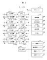
図2は、本発明によるルータ10のブロック構成図を示す。
ルータ10は、内部サブネットワーク3を構成する複数のセグメント3a、3b、3cを収容するための入力回線インタフェース11−1〜11−3および出力回線インタフェース12−1〜12−3と、外部サブネットワーク5a〜5nとの接続セグメント4a〜4nを収容するための入力回線インタフェース11−4〜11−nおよび出力回線インタフェース12−4〜12−nと、上記各入力回線インタフェースと内部バス19との間に接続された受信バッファ13(13−1〜13−n)と、上記各出力回線インタフェースと内部バス19との間に接続された送信バッファ14(14−1〜14−n)と、上記内部バス19に接続されたプロセッサ15、プログラムメモリ16およびデータメモリ17と、オペレータ用の入出力装置18とからなっている。
【0031】
プログラムメモリ16には、上記プロセッサ15によって実行されるプログラムとして、パケット送受信ルーチン200と、端末情報管理機能を備えたHDCPリレー処理ルーチン300と、ARP(Address Resolution Protocol)処理ルーチン400と、アプリケーションその他のルーチン500と、これらのルーチンを選択的に起動する基本制御ルーチン100が格納されている。また、データメモリ17には、ポート情報テーブル20と、端末管理テーブル30と、経路テーブル40と、ARPテーブル50、その他のデータ領域が形成される。
【0032】
ポート情報テーブル20は、ルータ10が備える入出力ポート(入出力回線インタフェース11、12)の識別子と、そのポートに接続されるセグメントのタイプとの対応関係を示す。この場合のセグメントタイプは、図1のマルチキャストセグメント3a〜3cのように、一つのサブネットアドレスを他のセグメントと共有するタイプ(以下、マルチセグメントと言う)か、セグメント4a〜4nのように、個別のサブネットアドレスをもつサブネットワークに接続される一般的なタイプかの区別を示している。
【0033】
端末管理テーブル30には、図3に示すように、内部サブネットワーク3に所属してルータ10をデフォルトルータとする各端末のMACアドレス31およびIPアドレス32と、該端末が接続されたセグメントの識別子33との対応関係を示す複数のエントリ30−1、30−2、…が登録される。
【0034】
経路テーブル40には、図4に示すように、宛先プリフィックス(Prefix)41と、次ホップ42と、出セグメント(出力ポート)識別子43との対応関係を示す複数のエントリ40−1、40−2、…が登録される。ここで、宛先プリフィックス41は、宛先サブネットワークのアドレスを示し、次ホップ42は、宛先サブネットワークへの中継ルータのIPアドレスを示す。
例えば、エントリ40−1のように、次ホップ42が“Connected”となっていた場合、宛先プリフィックス41で示された宛先サブネットワークがそのルータに直結していることを意味している。出セグメント識別子43は、次ホップ42で示されるルータの接続セグメント(出力ポート)の識別子を示している。
【0035】
宛先プリフィックス41で示されたサブネットワークが、図1の内部サブネットワーク3のように、複数のセグメントからなっている場合は、出セグメント識別子43には、このサブネットワークがマルチセグメントタイプとなっていることを示す識別コードが設定される。
【0036】
ARPテーブル50には、図5に示すように、端末に割当てられたIPアドレス51およびMACアドレス52と、エントリ有効期限を示すエージングタイマ値53との対応関係を示す複数のエントリ50−1、50−2、…が登録されている。
従来のIPネットワークでは、ルータに接続される各サブネットワークが一つのブロードキャストセグメントで構成されている。この場合、ルータは、受信パケットの宛先IPアドレスから宛先端末が接続されているセグメントを一義的に特定することができる。
【0037】
これに対して、図1に示すように、一つのサブネットワーク3を複数のブロードキャストセグメント3a、3b、3cで構成した場合、宛先IPアドレスから宛先端末が接続されているセグメントを一義的に特定することができない。端末管理テーブル30は、受信フレームの宛先MACアドレスまたは宛先IPアドレスから、宛先端末が接続されているセグメントを識別するために参照される。上記端末管理テーブル30へのエントリの登録は、例えば、DHCPサーバ6による端末へのIPアドレス割当てを利用して行われる。
【0038】
図6は、DHCPサーバ6による端末へのIPアドレスの割当てシーケンスを示す。
例えば、ユーザが端末2aを起動すると、端末2aは、DHCPサーバ検出用の制御メッセージ(DHCPDISCOVER)をセグメント3aにブロードキャストする。上記DHCP制御メッセージ(DHCPDISCOVER)は、例えば、図7に示すイーサフレーム(登録商標)60形式でブロードキャストセグメント3aに送出される。
【0039】
イーサフレーム60は、MACヘッダ61とペイロード62からなっており、ペイロード62に、IPヘッダ621と、UDPヘッダ622と、HDCP制御メッセージ(この例では、DHCPDISCOVERメッセージ)623とからなるIPパケット620が含まれる。
【0040】
DHCPDISCOVERメッセージを送信する場合、端末2aは、IPヘッダ621の宛先IPアドレスにブロードキャストアドレス、送信元IPアドレスにゼロを設定し、MACフレームヘッダ61の宛先アドレスにMACブロードキャストアドレス、送信元アドレスに自分のMACアドレスを設定する。
【0041】
ルータ10は、上記イーサフレームを受信すると、UDPヘッダから受信メッセージを処理すべき上位ルーチンを特定し、受信フレームをHDCPリレー処理ルーチン300に渡す。HDCPリレー処理ルーチン300は、HDCP制御メッセージを含むイーサフレーム60を受信すると、IPパケット620を抽出し、IPヘッダ621の送信元IPアドレスを自分のIPアドレスに書き換えた後、該IPパケットをDHCPサーバ6が接続されたサブネットワーク5aとの接続回線4aに転送する。
【0042】
DHCPサーバ6は、サブネットワーク5aから上記HDCP制御メッセージ(DHCPDISCOVER)を含むIPパケットを受信すると、要求元端末に割当てるべきIPアドレスを決定し、上記割当てIPアドレスを示す応答メッセージ(DHCPOFFER)を生成する。上記応答メッセージは、送信元IPアドレスにDHCPサーバ6のIPアドレスを含むIPパケット形式で、ルータ10宛に送信される。ルータ10は、上記応答メッセージ(DHCPOFFER)を含むIPパケットをHDCPリレー処理ルーチン300で処理し、イーサフレームとしてセグメント3aに転送する。
【0043】
端末2aは、上記応答メッセージ(DHCPOFFER)を受信すると、DHCPサーバにIPアドレスの割当て確認要求用のHDCP制御メッセージ(DHCPREQUEST)を送信する。上記DHCPREQUESTメッセージは、DHCPDISCOVERメッセージと同様、ブロードキャストMACフレーム形式でセグメント3aに送出され、ルータ10で送信元IPアドレスを書き換えた後、DHCPサーバ6に転送される。
【0044】
DHCPサーバ6は、上記DHCPREQUESTメッセージを受信すると、確認応答用のHDCP制御メッセージ(DHCPACK)を生成し、これをIPパケット形式でルータ10に送信する。ルータ10は、上記DHCPACKメッセージを含むIPパケットをHDCPリレー処理ルーチン300で処理し、イーサフレームとしてセグメント3aに転送する。上記DHCPACKメッセージを端末4aが受信することによって、IPアドレスの割当てシーケンスが完了する。
【0045】
HDCPリレー処理ルーチン300は、上述したHDCP制御メッセージの転送過程で、イーサフレームヘッダ61に含まれる端末のMACアドレスと、端末に割当てられたIPアドレスと、イーサフレーム受信セグメントの識別子との対応関係を把握し、DHCPACKメッセージの中継時に、端末管理テーブル30にIPアドレス要求元端末2aと対応する新たなエントリを登録する。
尚、IPアドレスを端末毎に固定アドレスとして割当てる場合は、ルータ10の管理者が、入出力装置18を介してマニュアル操作で端末管理テーブル30にエントリ登録するようにしてもよい。
【0046】
次に、本発明のルータ10によるIPパケットの中継動作と、ARP要求に対する代理応答動作について説明する。
先ず、同一の内部サブネットワーク3に属した2つの端末間でのパケット通信について説明する。
【0047】
一つのサブネットワークに属する全ての端末が同一のブロードキャストセグメントに接続される従来のネットワーク構成においては、上記サブネットワークに属する全ての端末間で直接パケットを送受信できるため、ルータによるパケット中継を必要としない。
従来のネットワーク構成において、例えば、端末Xが端末Yと通信する場合、端末Xは、端末YのMACアドレスを取得するために、端末YのIPアドレスを指定したARP要求メッセージをブロードキャストセグメントにブロードキャストする。端末Yは、上記ARP要求メッセージの受信に応答して、自己のMACアドレスとIPアドレスを組にした応答メッセージを要求元端末Xに返り返す。端末Xは、上記応答メッセージが示すMACアドレスを宛先アドレスに使用するによって、MACフレーム形式でデータパケットを端末Yに送信することができる。
【0048】
しかしながら、図1に示したネットワーク構成では、内部サブネットワーク3がマルチセグメントタイプとなっているため、内部サブネットワークで通信する2つの端末が同一ブロードキャストセグメントに属するとは限らない。このため、例えば、同一セグメントに接続された端末2aと端末2nとの間の通信のように、端末2aがセグメント3aにブロードキャストしたARP要求メッセージを宛先端末2nが受信し、要求元端末に応答メッセージを返送できる場合もあれば、例えば、端末2aと端末2bとの間の通信のように、端末接続セグメントが異なるため、端末2aがセグメント3aにブロードキャストしたARP要求メッセージを宛先端末2bで受信できない場合もある。
【0049】
そこで、本発明では、ARP要求メッセージの送信元端末Xの接続セグメントと、該ARPメッセージに応答すべき宛先端末Yの接続セグメントとが異なる場合、宛先端末Yに代わってルータ10にARP要求への応答動作を行わせる。
【0050】
例えば、図1のネットワークにおいて、端末2aが、端末2bのIPアドレスを指定して、ブロードキャストセグメント3aにARP要求メッセージを送信した時、ルータ10が、端末2bに代わって、端末2bのIPアドレスとルータ10のMACアドレスを示す応答メッセージを返答する。この場合、端末2aは、宛先端末2bから応答があったものと認識し、ルータ10のMACアドレスを宛先アドレスとするイーサフレームで端末2b宛のデータ(IPパケット)を送信する。
【0051】
ルータ10は、端末2aからのイーサフレームを受信すると、受信フレームからIPパケットを抽出し、宛先IPアドレスに従って受信パケットを転送する。この例では、受信パケットの宛先IPアドレスは端末2b宛となっているため、ルータ10は、経路テーブル40を参照した結果、宛先端末2bの属するサブネットワークが自ルータに直結されたマルチセグメントタイプのサブネットワークであることを認識し、端末管理テーブル30から、IPアドレス32が宛先IPアドレスと一致するエントリを検索する。
【0052】
端末管理テーブル30の検索の結果、宛先端末2bのMACアドレス31と接続セグメント(セグメント識別子)33が判明するため、ルータ10は、上記受信パケットをMACフレーム(イーサフレーム)形式で宛先端末2bの接続ポート(送信バッファ14−2)に転送することができる。
【0053】
ルータ10が、端末の代理でARP要求メッセージに返答する機能は、一般にProxy ARPと呼ばれている。本発明のルータ10は、ARP要求メッセージを受信すると、図8に示すARP処理ルーチン400を実行する。
ARP処理ルーチン400では、ARP要求メッセージの送信元端末(MACアドレス)が端末管理テーブル30にエントリ登録されているか否かを判定する(401)。送信元端末が端末管理テーブル30に未登録であれば、何もせずにこのルーチンを終了する。
送信元端末が端末管理テーブル30に登録済みの場合は、端末管理テーブル30から、IPアドレス32がARP要求メッセージで指定された宛先IPアドレスと一致するエントリを検索し、該エントリのセグメント識別子33が示す宛先端末の接続セグメントと、ARP要求メッセージの受信セグメント(入力ポート)とを比較する(402)。2つのセグメントが一致した場合は、宛先端末がARP要求メッセージに応答できると判断し、代理応答することなく、このルーチンを終了する。
【0054】
宛先端末の接続セグメントとARP要求メッセージの受信セグメントとが異なった場合は、宛先端末のIPアドレスとルータ10のMACアドレスを示す応答メッセージを生成し、これを上記ARP要求メッセージの受信セグメントと対応する出力ポートに送信し(403)、このルーチンを終了する。
【0055】
本発明のルータ10は、端末管理テーブル30によって内部サブネットワーク3に収容される全端末のIPアドレスを管理しているため、上述したように、端末管理テーブル30に登録エントリをもつ端末のみをProxy ARPの対象とすることによって、所在不明の端末からのパケット送信、または所在不明の端末宛のパケット送信を禁止することができる。
【0056】
マルチセグメントタイプの内部サブネットワーク3に接続された端末2aから外部ネットワーク5に接続された端末Yにパケットを送信する場合、端末2aは、端末Y宛のIPパケットを含むイーサフレームをデフォルトルータであるルータ10宛に送信する。ルータ10は、受信したイーサフレームからIPパケットを抽出し、経路テーブル40から該受信IPパケットの宛先IPアドレスに該当するエントリを検索し、受信IPパケットを次ホップ42と出セグメント43に従って転送する。
【0057】
外部ネットワーク5から端末2a宛のIPパケットを受信した場合、ルータ10は、経路テーブル40から受信IPパケットの宛先IPアドレスに該当するエントリを検索する。この場合、検索エントリの次ホップ42と出セグメント識別子43から、宛先端末の所属サブネットワークがルータ10に接続されたマルチセグメントタイプのものであることが判明するため、ルータ10は、端末管理テーブル30から上記宛先IPアドレスに該当するエントリを検索し、セグメント識別子33が示す出力ポートに受信IPパケットを転送する。
【0058】
次に、内部サブネットワーク3内で端末が移動した場合のルータ10の動作について説明する。
図1に示したブロードキャストセグメント3a〜3cは、例えば、一つの建物におけるフロア毎または居室毎に別セグメントとなるように敷設される。各端末ユーザは、現在位置から他の居室またはフロアに移動し、移動先のブロードキャストセグメントに自分の端末を接続し、他の端末と通信できると便利である。
【0059】
本発明のネットワーク構成によれば、端末がブロードキャストセグメント3a〜3c間で移動した場合でも、その端末が属するIPサブネットワーク3は不変となるため、端末のIPアドレスとデフォルトルータアドレスを変更する必要がない。
例えば、図1において、端末2aが現在のセグメント3aから隣のセグメント3bに移動しても、移動先で端末2aが所属するサブネットワークは、移動前と同じアドレスが「192.168.0.0/24」のネットワーク3である。従って、端末がブロードキャストセグメント3a〜3c間で移動しても、端末2aのIPアドレス「192.168.0.2」とデフォルトルータのIPアドレス「192.168.0.1」を変更する必要はない。
【0060】
このように、一つの内部サブネットワークを複数のブロードキャストセグメントで構成したことによって、端末が内部サブネットワークのセグメント間で移動しても、端末IPアドレスやデフォルトルータアドレスを変更することなく、各端末に移動先でのネットワーク通信を許容できる。従って、本発明のネットワーク構成によれば、ユーザによる端末パラメータの設定変更の負担を軽減し、移動先での移動前と継続した通信が可能になる。
【0061】
本発明のルータ10は、端末が移動先で送信する最初のイーサフレームを利用して、端末管理テーブル30のエントリ更新を行う。上記端末管理テーブルの更新には、例えば、移動前から継続する通信のデータパケットを含むイーサフレーム、新たに開始された通信のイーサフレーム、移動先のブロードキャストセグメントに接続した時に送信される認証用のイーサフレーム、端末アプリケーションが定期的に送信するイーサフレームなどを適用できる。
また、端末から送信されるイーサフレームは、IPパケット以外の、例えば、ARPメッセージやMicrosoft Windows(登録商標)で用いられるNetBEUI通信パケットを含むものでもよい。
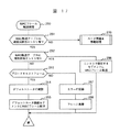
【0062】
図9は、ルータ10が実行するパケット送受信処理ルーチン200のフローチャートを示す。
受信バッファ13−1〜13−nに蓄積された受信フレームは、基本制御ルーチン100によって順次に読み出され、HDCP制御メッセージとARP要求メッセージ以外の受信フレームは、パケット送受信処理ルーチン200によって処理される。
【0063】
パケット送受信処理ルーチン200では、受信フレームの宛先MACアドレスをチェックし(201)、宛先MACアドレスが自ルータアドレスに一致しない受信フレームは廃棄して(217)、このルーチンを終了する。但し、宛先MACアドレス判定による受信フレームの廃棄は、入力回線インタフェース11−1〜11−nで行ってもよい。
【0064】
受信フレームの宛先MACアドレスが自ルータアドレスに一致していた場合は、受信フレームの入力ポートを判定する(210)。受信フレーム(イーサフレーム)の入力ポートがマルチセグメント接続ポート、すなわち、受信フレームが受信バッファ13−1〜13−3からの読み出しフレームの場合は、送信元のMACアドレスまたはIPアドレスが端末管理テーブル30に登録済みか否かを判定する(211)。
受信フレームの入力ポートが、マルチセグメント接続ポート以外のポート、すなわち、受信フレームが受信バッファ13−4〜13−nから読み出された外部サブネット接続セグメントからの受信フレームの場合は、図10で後述するIPパケット転送処理220を実行する。
【0065】
ステップ211での判定の結果、送信元に該当するエントリが端末管理テーブル30に未登録の場合は、受信フレームが内部サブネットワークに接続された不正端末からのものと判断し、エラー情報を記録(216)した後、受信フレームを廃棄し(217)、このルーチンを終了する。
【0066】
送信元に該当するエントリが端末管理テーブル30に登録済みの場合は、上記受信フレームの入力ポート(受信セグメント)の識別子が端末管理テーブル30に登録済みのセグメント識別子33と一致するか否かを判定する(212)。2つの識別子が一致した場合は、受信フレームの送信元端末に移動はなく、端末管理テーブル30は更新不要と判断して、受信フレームから抽出されたIPパケットについて、IPパケット転送処理220を実行する。
【0067】
受信セグメントの識別子が端末管理テーブル30に登録済みのセグメント識別子33と一致しなかった場合は、受信フレームの送信元端末に移動があったものと判断し、送信元端末の移動確認処理(213)を実行する。端末の移動は、端末管理テーブル30に登録されている送信元端末のMACアドレス31を宛先とする確認フレーム(Pingフレーム)を生成し、これをセグメント識別子33が示す端末移動前のセグメントと、上記受信フレームの入力ポートと対応する端末移動先のセグメントに送信し、各セグメントにおける応答フレームの受信の有無によって確認する。
【0068】
端末がセグメント間で移動した場合は、移動先セグメントにおいてのみ宛先端末が上記Pingフレームに応答するはずである。移動先セグメントで上記Pingフレームに応答が無かった場合は、送信元端末に異常が発生したものと判断できる。また、移動前のセグメントに送信したPingフレームに対して応答があった場合は、同一MACアドレスをもつ宛先端末が2箇所に存在すると言う異常状態の発生を意味している。端末の移動確認処理の結果(214)、受信フレームの送信元端末の移動に異常があった場合は、エラーを記録し(216)、受信フレームを廃棄(217)して、このルーチンを終了する。
【0069】
移動前のセグメントで応答が無く、移動先のセグメントで応答があった場合に、正常な端末移動と判断する。この時、端末管理テーブル30に登録されている上記送信元端末に該当するエントリのセグメント識別子33を移動後のセグメントの識別子に書き換え(215)、受信フレームから抽出されたIPパケットについて、IPパケット転送処理220を実行する。
【0070】
図10は、IPパケット転送処理220の詳細を示すフローチャートである。IPパケット転送処理220では、経路テーブル40から受信IPパケットの宛先アドレスに該当するエントリを検索し(221)、宛先アドレスに該当するエントリが無かった場合は、エラー情報を記録(229)した後、受信パケットを廃棄して(230)、このルーチンを終了する。
【0071】
経路テーブル40に宛先アドレスに該当するエントリがあった場合は、出セグメント識別子43の値から、宛先端末がマルチセグメントタイプの内部サブネットワークに接続された端末か否かを判定する(222)。宛先端末がマルチセグメントタイプ内部サブネットワークの接続端末の場合は、端末管理テーブル30を参照し、宛先IPアドレスに該当するエントリが登録済みか否かを判定し(223)、未登録の場合は、エラー情報を記録(229)した後、受信パケットを廃棄して(230)、このルーチンを終了する。
【0072】
宛先端末が通常セグメントに接続された端末の場合、または、ステップ223で端末管理テーブル30にエントリ登録済みであることが確認された端末の場合は、ARPテーブル50を参照し、宛先IPアドレスに該当するエントリがARPテーブル50に登録済みか否かを判定する(224)。宛先IPアドレスに該当するエントリが登録済みであれば、IPパケットの転送(228)を行う。
【0073】
上記IPパケット転送(228)では、ARPテーブル50に登録されたMACアドレスを宛先MACアドレスに適用して、受信IPパケットを含むMACフレームを生成し、経路テーブル40の出セグメント識別子43、または端末管理テーブル30のセグメント識別子33が示す宛先端末の接続ポートにMACフレームを転送する(228)。
【0074】
宛先IPアドレスに該当するエントリがARPテーブル50に未登録の場合は、宛先端末のMACアドレスを取得するためのARP要求メッセージを生成し、これを経路テーブル40の出セグメント識別子43、または端末管理テーブル30のセグメント識別子33が示す宛先端末の接続ポートに送信する(225)。上記ARP要求メッセージに対する応答を待ち、所定時間内に応答がなければ、エラー情報を記録(229)し、受信パケットを廃棄して(230)、このルーチンを終了する。
【0075】
ARP要求に対する応答メセージを受信した場合は、応答メッセージの内容に従って宛先端末用のARP情報エントリを生成し、これをARPテーブル50に追加(227)した後、上述したIPパケット転送(228)を実行する。
【0076】
図11は、上述したマルチセグメントタイプのサブネットワーク3に含まれるセグメント本数を増加し、端末の移動範囲を拡張するのに適したルータ構成の1例を示す。
本実施例では、ルータ10が備えるマルチセグメント接続用の入出力ポート3A〜3B(入力回線インタフェース11−1〜11−3、出力回線インタフェース12−1〜12−3)にVLANスイッチ(7a〜7c)を接続し、これらのVLANスイッチにそれぞれ複数本のマルチキャストセグメント3a−1〜3a−N、3b−1〜3b−N、3c−1〜3c−Nを収容している。
【0077】
VLANスイッチ7aは、マルチキャストセグメントとなる複数の物理回線3a−1〜3a−Nを集線し、これらの物理回線での送信フレームを入出力ポート3Aに論理的に多重/分離する機能を備えている。VLANによって複数の回線を多重化することにより、ルータ10が提供できる少数の入出力ポートに多数のブロードキャストセグメントを収容することが可能となる。尚、VLANは、IEEE802.1Q規格において標準化されている。
【0078】
図12は、本発明の第2実施例となるルータを適用したネットワークの概略図を示す。
第2実施例は、それぞれがマルチセグメント構造のサブネットワークを収容する複数台のルータを接続し、端末のIPアドレスを変更することなく、これらのサブネットワーク間での端末の移動を許容できるようにしたものである。
【0079】
図12において、ルータ10Aは、ネットワークアドレス「192.168.0.0/24」をもつIPサブネットワーク3Aのデフォルトルータ(IPアドレス:「192.168.0.1」をもつデフォルトゲートウェイ)となっている。また、ルータ1Bは、ネットワークアドレス「192.168.1.1/24」をもつIPサブネットワーク3Bのデフォルトルータ(IPアドレス:「192.168.1.1」をもつデフォルトゲートウェイ)となっている。
【0080】
ルータ10Aには、IPサブネットワーク3Aに所属する端末2a(IPアドレス:「192.168.0.2」)、端末2b(IPアドレス:「192.168.0.3」)、端末2c(IPアドレス:「192.168.0.4」)が、それぞれブロードキャストセグメント3a、3b、3cを介して収容されている。
【0081】
また、ルータ10Bには、IPサブネットワーク3Bに所属する端末2d(IPアドレス:「192.168.1.2」)、端末2e(IPアドレス:「192.168.1.3」)、端末2f(IPアドレス:「192.168.1.4」)が、それぞれブロードキャストセグメント3d、3e、3fを介して収容されている。
これらのルータ10A、10Bは、回線3xを介して接続してあり、後述するように、上記回線3xを介して、他のサブネットワークから移動してきた端末からの受信イーサフレームを相互に転送できるようになっている。
【0082】
第1実施例と同様、各端末は、起動時にルータ10Aまたは10Bを介してDHCPサーバ6をアクセスし、その端末の収容ルータをデフォルトゲートウェイとするIPサブネットワーク対応のIPアドレスの割当てを受ける。本実施例では、ルータ10A、10Bが、例えば、サブネットワーク5nに接続されたデフォルトルータ管理サーバ8をアクセスすることによって、他方のルータに収容された端末のアドレス情報を取得する。
【0083】
デフォルトルータ管理サーバ8は、ルータ10A、10Bに収容されている各端末のアドレス情報を保持するために、例えば、図15に示すデフォルトルータ管理テーブル80を備えている。デフォルトルータ管理テーブル80には、端末のMACアドレス81およびIPアドレス82と、その端末のデフォルトルータ(デフォルトゲートウェイ)の識別子83との関係を示す複数のエントリ80−1、80−2、・・・が登録される。
【0084】
ルータ10A、10Bは、自分の端末管理テーブル30に新たなエントリを登録した時、端末のMACアドレス31およびIPアドレス32と、自分のルータ識別子をデフォルトルータ管理サーバ8に通知する。デフォルトルータ管理サーバ8は、これらの情報から新たなエントリ80−iを生成し、これをデフォルトルータ管理テーブル80に登録する。
【0085】
図13は、第2実施例のルータ10(10A、10B)の構成を示す。
本実施例のルータ10は、図2に示した第1実施例のルータ10に、回線3xに接続された入力回線インタフェース11−xおよび出力回線インタフェース12−xと、これらのインタフェースとバス19との間に接続された受信バッファ13−xおよび送信バッファ14−xとを追加し、メモリ17にMAC転送テーブル60を追加し、パケット送受信処理ルーチン200Xに新たな機能を追加した構成となっている。
【0086】
MAC転送テーブル60には、図14に示すように、端末およびデフォルトルータのMACアドレス61と、その端末またはデフォルトルータが接続されたセグメントの識別子62と、エントリの有効期限を示すエージングタイマ値63とを示す複数のエントリ60−1、60−2、・・・が登録される。デフォルトルータ用のエントリは、システム構築時にオペレータ操作によって登録される。デフォルトルータ用のエントリのセグメント識別子62には回線3xの識別子が設定され、エージングタイマ値63は、時間制限を受けない特殊な設定値となっている。
【0087】
本実施例におけるパケット送受信処理ルーチン200Xは、経路テーブル40に基づくIPパケットの転送機能に加えて、上記MAC転送テーブル60を用いたイーサフレームの中継機能を備えている。イーサフレームの中継機能は、後述するように、端末がデフォルトルータ(デフォルトゲートウェイ)間で移動した時に使用される。
【0088】
例えば、図12において、端末2aが、同一のサブネットワークに属したセグメント3aからセグメント3bまたは3cに移動した場合、ルータ10Aは、第1実施例のルータ10と同様の動作を行う。端末2aが、サブネットワーク3Aに属したセグメント3aから、別のサブネットワーク3Bに属したセグメント3d〜3fに移動した場合、異なるデフォルトルータ間(サブネットワーク間)の端末移動になるため、ルータ10A、10Bには、第1実施例にはない特殊な機能が必要となる。
【0089】
図16は、10A、10Bが実行するパケット送受信処理ルーチン200Xのフローチャートを示す。
パケット送受信処理ルーチン200Xでは、受信フレームに付された宛先MACアドレスを判定し(201)、宛先MACアドレスが自ルータMACアドレスと一致していれば、上記フレームの受信ポートを判定し(210)、以下、第1実施例のパケット送受信処理ルーチン200と同様の処理ステップ211〜220を実行する。
【0090】
受信フレームに付された宛先MACアドレスが自ルータMACアドレスと一致しなかった場合は、MACフレーム転送処理250を実行する。MACフレーム転送処理250では、図17に示すように、MAC転送テーブル60から、MACアドレス61が上記受信フレームの送信元MACアドレスに一致するエントリを検索する(251)。MAC転送テーブル60に送信元MACアドレスに一致するエントリが未登録の場合は、図18で後述するルータ間端末移動処理270を実行する。
【0091】
MAC転送テーブル60に送信元MACアドレスに一致するエントリが登録済みの場合は、MAC転送テーブル60から、MACアドレス61が上記受信フレームの宛先MACアドレスに一致するエントリを検索する(252)。宛先MACアドレスに一致するエントリがあった場合は、該エントリのセグメント識別子62が指定する出力ポートに受信フレーム(MACフレーム)を転送する(256)。
【0092】
例えば、ルータ10Aをデフォルトルータとする端末2aが、ルータ10Bに収容されたセグメント3dに移動し、デフォルトルータを宛先MACアドレスとするMACフレームを送信した場合、もし、端末2aのエントリがMAC転送テーブルに登録済みであれば、上記ステップ255で、受信MACフレームが回線2x宛に転送される。
【0093】
MAC転送テーブル60に宛先MACアドレスに一致するエントリが未登録の場合は、受信フレームがブロードキャストフレームか否かを判定し(253)、ブロードキャストフレームでなければ、エラー情報を記録し(257)、受信フレームを廃棄して(258)、このルーチンを終了する。
【0094】
受信フレームがブロードキャストフレームの場合は、デフォルトルータ管理サーバ8に、上記受信フレームの送信元MACアドレスと対応するデフォルトルータを問合せ(254)、デフォルトルータの接続セグメントに受信フレーム(MACフレーム)を転送する(255)。
【0095】
ルータ間端末移動処理270は、MAC転送テーブル60に受信フレームの送信元MACアドレスが未登録の時、送信元端末が他のサブネットワークから移動して来たものとの判断に基づいて実行される。
ルータ間端末移動処理270では、図18に示すように、デフォルトルータ管理サーバ8に、上記受信フレームの送信元MACアドレスと対応するデフォルトルータを問合せる(271)。デフォルトルータ管理サーバ8からの応答によって、デフォルトルータ管理テーブル80に上記送信元MACアドレスと対応するエントリが未登録と判った場合は(272)、エラー情報を記録し(275)、受信フレームを廃棄して(276)、このルーチンを終了する。
【0096】
デフォルトルータ管理サーバ8から、上記送信元MACアドレスと対応するデフォルトルータの回答があった場合は、デフォルトルータの接続セグメントに受信フレーム(MACフレーム)を転送し(273)、MAC管理テーブル60に上記送信元MACアドレスと対応するエントリを登録して(274)、このルーチンを終了する。
【0097】
上記MAC転送テーブル60への新たなエントリの登録によって、同一端末からその後に受信するMACフレームは、デフォルトルータ管理サーバへのデフォルトルータの問合せを行うことなく、送信元端末のデフォルトルータに転送することが可能となる。
【0098】
例えば、図12のネットワークにおいて、ルータ10Aをデフォルトルータ(デフォルトゲートウェイ)とする端末2aが、セグメント3aからセグメント3dに移動し、ルータ10AのMACアドレスを宛先とするMACフレームをセグメント3dに送信した場合、ルータ10Bは、MACフレーム転送処理250とルータ間端末移動処理270を実行し、受信MACフレームをデフォルトルータ管理サーバ8から通知された上記端末2aのデフォルトルータ10Aとの接続セグメント、この例では回線3xの接続ポートに転送することになる。
【0099】
また、ステップ274で、MAC転送テーブル60に端末2a用のエントリを登録したことによって、その後に端末2aが送信したMACフレームをMACフレーム転送処理250において回線3xの接続ポートに転送することになる。
従って、セグメント3aで端末2bと通信していた端末2aが、移動先のブロードキャストセグメント3dで端末2bとの通信する場合でも、ユーザは、端末2aの接続セグメントが変ったことを意識することなく、従前と同様の手順で通信を開始できる。
【0100】
尚、第2実施例においては、ルータ10A(10B)は、自分のサブネットワーク3Aに所属した端末以外に、ルータ10B(10A)をデフォルトルータとする移動端末からもARP要求メッセージを受信する場合がある。例えば、図12のネットワークにおいて、端末2dが、移動先のセグメント3cで、端末2eのIPアドレスを指定したARP要求メッセージをブロードキャストした場合、ルータ10Aは、受信したARP要求メッセージをルータ10Bに転送し、ルータ10Bに代理応答させる必要がある。
【0101】
このようなARP要求メッセージのルータ間転送を実現するためには、例えば、図8に示したARP処理ルーチン400において、ステップ401で、受信メッセージの送信元端末が端末管理テーブルに未登録の端末と判明した時、受信メッセージの宛先アドレスがブロードキャストアドレス(受信メッセージがARP要求メッセージ)の場合、図18に示したルータ間の端末移動処理270と同様の処理を実行し、宛先アドレスがブロードキャストアドレス以外の個別の端末アドレスを示していた場合(受信メッセージが応答メッセージの場合)は、更に宛先アドレスがMAC転送テーブルに登録済みか否かを判定し、登録済みであれば、登録されたセグメントに受信フレームを転送するようにすればよい。
【0102】
このようにすれば、ルータ10Aは、端末2dが送信したARP要求をルータ10BにMAC転送でき、ルータ10Bが宛先端末2eの代理で生成した応答メッセージを回線3xから受信した時、これをARP要求メッセージの送信元である端末2dに転送することが可能となる。
【0103】
上述した第2実施例によれば、ルータ10A、10Bが、回線3xを介して互いに相手ルータ宛のMACフレームを送受信する機能を備えたことによって、図12に実線で示したマルチセグメント構造のサブネットワーク3A、3Bの範囲を破線で示した範囲にまで実質的に拡張することが可能となる。
【0104】
尚、第2実施例のルータ10A、10Bは、外部のサブネットワークに対しては、互いに独立したルータとして機能する。例えば、サブネットワーク5aに経路情報を配布する場合、ルータ10Aは、内部サブネットワーク3Aのアドレス「192.168.0.0/24」と、ルータ10Aに接続されたサブネットワーク5a以外の外部サブネットワーク(5b〜5n)のサブネットアドレスを配布する。
【0105】
同様に、ルータ10Bは、内部サブネットワーク3Aのアドレス「192.168.1.1/24」と、ルータ10Bに接続されたサブネットワーク5a以外の外部サブネットワーク(5b〜5n)のサブネットアドレスを配布する。これは、サブネットワークに属する端末が、他方のルータが収容するブロードキャストセグメントに移動した場合も不変である。
このように、端末の物理的な位置に関係なく、経路情報を常にサブネットワーク単位で扱うことによって、経路制御機能にかける負担を低減できる。
【0106】
以上の実施例では、ルータ10が、マルチセグメントタイプの内部サブネットワークを介して端末を収容しているが、本発明のルータは、端末接続用の内部サブネットワークとして、マルチセグメントタイプの内部サブネットワークの他に、単一セグメントタイプの通常の内部サブネットワークを備えてもよい。但し、後者の内部サブネットワークに所属する端末は、外部サブネットワークに接続された端末と同様に扱われるため、本発明による端末移動の利点を享受することはできない。
【0107】
【発明の効果】
以上で説明したように、本発明によれば、一つのサブネットワークを複数のブロードキャストセグメントで構成し、パケット転送装置で各端末と接続セグメントとの対応関係を自動的に管理することによって、端末IPアドレスやデフォルト装置アドレスなどの設定値を変更することなく、セグメントを越えた端末の移動を許容することが可能になる。
【図面の簡単な説明】
【図1】 本発明のルータが適用されるネットワーク構成の1例を示す概略図。
【図2】 本発明によるルータ10の第1実施例を示すブロック構成図。
【図3】 ルータ10が備える端末管理テーブル30の内容を示す図。
【図4】 ルータ10が備える経路テーブル40の内容を示す図。
【図5】 ルータ10が備えるARPテーブル50の内容を示す図。
【図6】 DHCPサーバ6による端末へのIPアドレスの割当てシーケンスを示す図。
【図7】 イーサフレームのフォーマットを示す図。
【図8】 ルータ10が実行するARP処理ルーチン400の1実施例を示すフローチャート。
【図9】 ルータ10が実行するパケット送受信処理ルーチン200の1実施例を示すフローチャート。
【図10】 図9におけるIPパケット転送処理220の詳細を示すフローチャート。
【図11】 マルチセグメント構造のサブネットワークを大規模化するのに好適なルータ構造の1例を示す図。
【図12】 本発明によるルータが適用されるネットワーク構成の他の例を示す概略図。
【図13】 本発明によるルータ10の第2実施例を示すブロック構成図。
【図14】 第2実施例のルータ10が備えるMAC転送テーブル60の内容を示す図。
【図15】 図12におけるデフォルトルータ管理サーバ8が備えるデフォルトルータ管理テーブルの内容を示す図。
【図16】 第2実施例のルータ10が実行するパケット送受信処理ルーチン200Xのフローチャート。
【図17】 図16におけるMACフレーム転送処理250の詳細を示すフローチャート。
【図18】 図16におけるルータ間端末移動処理270の詳細を示すフローチャート。
【符号の説明】
10:ルータ、3、3A、3B:内部サブネットワーク、
3a〜3f:ブロードキャストセグメント、4a〜4n:外部サブネット接続セグメント、5a〜5n:外部サブネットワーク、6:DHCPサーバ、
8:デフォルトルータ管理サーバ、10:ルータ、20:ポート管理テーブル、30:端末管理テーブル、40:経路テーブル、50:ARPテーブル、
60:MAC転送テーブル、200、200X:パケット送受信処理ルーチン、400:HDCPリレー処理ルーチン、400:ARP処理ルーチン。[0001]
BACKGROUND OF THE INVENTION
The present invention relates to a packet transfer apparatus, and more particularly to a packet transfer apparatus that connects a plurality of broadcast segments that allow movement of a connected communication terminal between segments.
[0002]
[Prior art]
In an IP network, for example, a plurality of broadcast segments constructed by Ethernet (registered trademark) or the like are interconnected by a packet transfer device called an L3 switch or a router. In this case, the broadcast segment corresponds to a network unit generally called a subnetwork.
[0003]
The address of each subnetwork is expressed as “192.168.0.0/24”, for example. Here, the numeric string “192.168.0.0” represents a 32-bit address part value, and the address bit value is represented by a decimal number from 0 to 255 in byte units. The 32-bit address part includes a first bit group indicating a subnetwork address and a first group indicating a host address. 2 The numerical value “24” after the slant mark indicates the number of bits of the subnet mask.
[0004]
In the example shown here, the value “192.168.0” of the upper 24 bits of the address part indicated by the subnet mask indicates the subnetwork address, and the lower 1 byte indicates the host address. The host address is used as an identifier of each terminal belonging to the subnet. When the router receives an IP packet from one subnetwork, the router recognizes the destination subnetwork from the subnetwork address portion of the destination IP address included in the IP header, and outputs the received packet corresponding to the connection segment of the destination subnetwork. Forward to port.
[0005]
Each terminal is assigned an IP address having the same address value as the subnetwork to which the terminal is connected in the upper bit part. Therefore, when the terminal moves from the home subnetwork to another subnetwork, it is necessary to change the IP address of the terminal. For example, when Ethernet is used for the data link layer, the subnetwork corresponds to an Ethernet broadcast segment. Therefore, when the terminal moves from one broadcast segment to another broadcast segment, it is necessary to change the IP address of the terminal.
[0006]
Usually, a subnetwork is defined in consideration of network management requirements such as traffic separation and security. Therefore, for example, in many cases, subnetworks are defined for each room or floor of an office building, and each is an independent broadcast segment.
In recent years, notebook PCs and portable terminals that are small, light, and easy to carry have become widespread as terminals for IP networks, and with the practical application of wireless LAN, it has become possible to easily connect terminals and networks at destinations. It is coming.
[0007]
[Problems to be solved by the invention]
In such a situation, a communication service that allows each terminal to move between sub-networks (or broadcast segments) without changing the terminal IP address so that the terminal user can easily use the network at the destination. The demand for is increasing. In order to facilitate the use of the network at the destination, for example, there are the following methods.
(1) A network configuration in which a subnetwork (broadcast segment) is enlarged and a moving range of terminals, for example, an entire area of an office building is covered by one subnetwork. In this case, a plurality of wireless access points are provided in one subnetwork.
[0008]
According to this method, since each terminal can always be connected to the same subnetwork at the destination, there is no need to change the terminal IP address and the IP address of the default router. However, in this method, since all terminals are accommodated in one broadcast segment, there is a problem that traffic is concentrated on the same network and a communication band that can be used by each terminal is insufficient. Also, since broadcast traffic reaches all terminals, security is not sufficient.
(2) A network configuration employing mobile IP defined by RFC 2002 of IETF. In Mobile IP, a home agent (HA) function is arranged in the sub-network that is the home link of each terminal, and a foreign agent (FA) function is arranged in the destination link. When moving to an external subnetwork (visited network), the correspondence between the home address of the terminal and the care-of address (CoA: Care of Address) acquired by the visited network is notified to the home agent HA (terminal location registration) Let
[0009]
The source terminal of the IP packet sets the home address of the receiving terminal as the destination address and transmits the IP packet. The IP packet is captured by the home agent HA, transferred to the receiving terminal's visited network in an encapsulated form with an IP header having a care-of address corresponding to the home address as a destination address, decapsulated by the foreign agent FA, Transferred to the receiving terminal. Therefore, in the mobile IP, each terminal needs to have a mobile IP function for performing location registration from the visited network to the home agent HA.
(3) For example, as proposed in Japanese Patent Laid-Open No. 2002-135289, a router that detects the movement of a terminal distributes the IP address of the mobile terminal to other routers, thereby providing a routing table included in each router. A network configuration of a host address routing method in which the contents of the (route table) are changed as the terminal moves.
[0010]
According to this method, each terminal can always use the same IP address, but each router in the network needs to hold / update the route information of all the terminals. There is a problem that increases. For this reason, it is necessary to devise measures for suppressing the path control burden, such as suppressing the network configuration change as much as possible, for example, performing path control in units of sub-networks.
[0011]
[Patent Literature]
JP 2002-135289 A
[0012]
[Means for Solving the Problems]
An object of the present invention is to provide a packet transfer apparatus that can easily perform inter-terminal communication without changing a terminal IP address at a destination.
Another object of the present invention is to provide a packet transfer apparatus in which a terminal can move between a plurality of segments.
Another object of the present invention is to provide a packet transfer apparatus that can increase the number of segments included in the movement range of a terminal.
[0013]
In order to achieve the above object, the packet transfer apparatus of the present invention comprises one sub-network composed of a plurality of broadcast segments, and allows each terminal to use the same IP address in the sub-network.
In general, since a subnetwork managed by a router is composed of one broadcast segment, a conventional router identifies a subnetwork to which a destination terminal belongs by using, for example, an IP route control function, and this subnetwork is defined by RFC826. By broadcasting an ARP (Address Resolution Protocol) request message, the MAC address of the destination terminal is obtained, and the received IP packet is converted into a MAC frame.
[0014]
However, when one subnetwork is formed by a plurality of broadcast segments, it is not possible to uniquely identify one segment to broadcast the ARP request message from the destination IP address of the received packet. Therefore, in the packet transfer apparatus of the present invention, the ARP request message and the received IP are referred to with reference to a table (hereinafter referred to as a terminal management table) indicating the correspondence between the MAC address and IP address of the terminal and the connection segment of the terminal. A segment to which a MAC frame including a packet is transferred is specified.
[0015]
That is, the packet transfer apparatus of the present invention has a packet transfer control unit that transfers IP packets between a plurality of broadcast segments, and each of the plurality of broadcast segments accommodates a plurality of terminals. To form an internal subnetwork with one subnet address,
The packet transfer control unit includes a terminal management table storing a plurality of entries indicating the correspondence between the MAC address and IP address of each terminal belonging to the internal subnetwork and the segment to which the terminal is connected. When a MAC frame specifying a terminal connected to another segment in the internal sub-network with a destination IP address is received from a source terminal connected to any segment in the internal sub-network, the received frame Is transferred to the connection segment of the destination terminal according to the terminal management table.
[0016]
Registration of entries in the terminal management table can be automatically performed in conjunction with address allocation to terminals by DHCP (Dynamic Host Configuration Protocol) defined in RFC2131, for example. When a fixed IP address is assigned to each terminal, an entry may be set manually.
[0017]
Another feature of the packet transfer apparatus according to the present invention is that it receives an address request message for inquiring about the MAC address of the destination terminal by designating the destination IP address from the source terminal connected to any segment in the internal sub-network. When the destination terminal connection segment and the address request message reception segment are different from each other by referring to the terminal management table to determine the identity of the connection segment of the destination terminal and the reception segment of the address request message. In addition, instead of the destination terminal, there is provided means for transmitting a response message including the IP address of the destination terminal and the MAC address of the router to the connection segment of the source terminal.
[0018]
In this way, the packet transfer device makes a proxy response to the MAC address, so that the MAC frame including the IP packet addressed to the terminal connected to another segment is captured by the packet transfer device, and the connection segment of the destination device according to the terminal management table. Can be transferred to.
[0019]
Another feature of the packet transfer apparatus according to the present invention is that when a MAC frame is received from a transmission source terminal connected to any segment in the internal subnetwork, the received segment of the MAC frame and the transmission of the MAC frame The connection segment stored in the terminal management table corresponding to the original MAC address is collated, and if they do not match, it is determined that the transmission source terminal has moved within the internal subnetwork and stored in the terminal management table A table updating means for changing the connected segment to the received segment of the MAC frame.
[0020]
In this way, by updating the terminal management table according to the movement of the terminal, it is possible to move each segment to each terminal without changing the network settings such as the terminal IP address at the movement destination and the IP address of the default transfer device. Is acceptable.
[0021]
According to one embodiment of the present invention, the table updating means sends a confirmation message addressed to the source address of the MAC frame when the received segment of the MAC frame does not match the connection segment stored in the terminal management table. Necessity of updating the connection segment stored in the terminal management table by checking whether or not the terminal has been properly transmitted based on the reception status of the response to the confirmation message in both segments transmitted to the reception segment and the connection segment To decide.
[0022]
For example, RFC 3069 describes “VLAN Aggregation for Efficient IP Address Allocation” for a subnetwork composed of a plurality of broadcast segments. However, the conventional technology described here saves IP addresses allocated to terminals. This is not intended for terminal movement between segments as described above.
[0023]
Still another feature of the packet transfer apparatus according to the present invention is as follows:
A connection line for sending and receiving MAC frames to and from neighboring packet transfer devices in a cooperative relationship;
From the source terminal connected to any segment in the internal subnetwork, specify the packet forwarding device with the destination MAC address, and specify the terminal connected to another segment in the internal subnetwork with the destination IP address A packet transfer control unit that transfers an IP packet included in the received frame to the segment to which the destination terminal is connected when the received MAC frame is received;
When a MAC frame is received from a terminal using the adjacent packet transfer device as a default device via any segment of the internal subnetwork, the MAC frame is transferred to a connection line with the adjacent packet transfer device. And a transfer control unit.
[0024]
In this case, the packet control unit controls inter-segment IP packet transfer in the internal subnetwork according to the terminal management table described above, and the MAC frame transfer control unit includes a plurality of correspondence relationships between MAC addresses and connection segments. The MAC frame transfer to the adjacent packet transfer device is controlled according to the MAC transfer table storing the entries. In addition, the MAC frame transfer control unit processes a received MAC frame whose destination MAC address is a MAC address other than the packet transfer device, and an entry corresponding to the source terminal of the received MAC frame is not registered in the MAC transfer table. Confirms that the default device of the source terminal is an adjacent packet transfer device, transfers the received MAC frame to the adjacent packet transfer device, and registers the entry for the source terminal in the MAC transfer table. I do.
In this way, by providing the packet transfer device with the function of transmitting and receiving MAC frames to and from neighboring packet transfer devices that have a cooperative relationship, each terminal is not limited to inter-segment movement within the subnetwork formed by the default device. In addition, movement to a subnetwork formed by an adjacent packet transfer apparatus can be permitted.
[0025]
In the packet transfer apparatus according to the present invention, the packet transfer control unit described above includes a route table in which a plurality of entries indicating route control information corresponding to subnetwork addresses are registered, and the internal sub-register registered in the route table is provided. The entry corresponding to the address of the network includes a segment identifier indicating that the internal subnetwork is composed of a plurality of segments, and an IP packet addressed to a terminal belonging to the internal subnetwork from a segment connected to the external subnetwork. When the packet is received, the packet transfer control unit refers to the route table and the terminal management table, specifies the connection segment of the destination terminal, and transfers the received packet to the specified segment. Other objects and features of the present invention will become apparent from the embodiments described below.
[0026]
DETAILED DESCRIPTION OF THE INVENTION
Hereinafter, embodiments of the present invention will be described with reference to the drawings.
FIG. 1 is a schematic diagram of a network to which a packet transfer apparatus (hereinafter referred to as a “router” including a
Here, the function of the
[0027]
In this embodiment, the
[0028]
The
As can be seen from the relationship between the IP addresses, one feature of the present embodiment is that the
[0029]
The
[0030]
FIG. 2 shows a block diagram of the
The
[0031]
In the
[0032]
The port information table 20 shows the correspondence between the identifiers of the input / output ports (input / output line interfaces 11 and 12) provided in the
[0033]
As shown in FIG. 3, the terminal management table 30 includes a
[0034]
As shown in FIG. 4, the routing table 40 includes a plurality of entries 40-1 and 40-2 indicating a correspondence relationship between a destination prefix (Prefix) 41, a
For example, as in the entry 40-1, the
[0035]
When the subnetwork indicated by the
[0036]
As shown in FIG. 5, the ARP table 50 includes a plurality of entries 50-1 and 50-50 indicating the correspondence between the
In a conventional IP network, each subnetwork connected to a router is composed of one broadcast segment. In this case, the router can uniquely identify the segment to which the destination terminal is connected from the destination IP address of the received packet.
[0037]
On the other hand, as shown in FIG. 1, when one
[0038]
FIG. 6 shows an IP address assignment sequence to the terminal by the
For example, when the user activates the terminal 2a, the
[0039]
The
[0040]
When transmitting the DHCPDISCOVER message, the terminal 2a sets the broadcast address as the destination IP address of the
[0041]
When the
[0042]
When receiving the IP packet including the HDCP control message (DHCPDISCOVER) from the
[0043]
When the terminal 2a receives the response message (DHCPOFFER), the terminal 2a transmits an IPCP assignment confirmation request HDCP control message (DHCPREQUEST) to the DHCP server. Similar to the DHCPDISCOVER message, the DHCPREQUEST message is sent to the
[0044]
When the
[0045]
The HDCP
When an IP address is assigned as a fixed address for each terminal, an administrator of the
[0046]
Next, an IP packet relay operation and a proxy response operation to the ARP request by the
First, packet communication between two terminals belonging to the same
[0047]
In a conventional network configuration in which all terminals belonging to one subnetwork are connected to the same broadcast segment, packets can be directly transmitted and received between all terminals belonging to the subnetwork, so that packet relaying by a router is not required. .
In the conventional network configuration, for example, when the terminal X communicates with the terminal Y, the terminal X broadcasts an ARP request message specifying the IP address of the terminal Y to the broadcast segment in order to acquire the MAC address of the terminal Y. . In response to receiving the ARP request message, the terminal Y returns a response message in which its own MAC address and IP address are paired back to the requesting terminal X. The terminal X can transmit the data packet to the terminal Y in the MAC frame format by using the MAC address indicated by the response message as the destination address.
[0048]
However, in the network configuration shown in FIG. 1, since the
[0049]
Therefore, in the present invention, when the connection segment of the transmission source terminal X of the ARP request message is different from the connection segment of the destination terminal Y that should respond to the ARP message, the
[0050]
For example, in the network of FIG. 1, when the terminal 2a specifies the IP address of the terminal 2b and transmits an ARP request message to the
[0051]
When the
[0052]
As a result of searching the terminal management table 30, the
[0053]
The function in which the
In the
When the transmission source terminal has been registered in the terminal management table 30, an entry in which the
[0054]
When the connection segment of the destination terminal and the reception segment of the ARP request message are different, a response message indicating the IP address of the destination terminal and the MAC address of the
[0055]
Since the
[0056]
When a packet is transmitted from the terminal 2a connected to the multi-segment type
[0057]
When receiving an IP packet addressed to the terminal 2a from the
[0058]
Next, the operation of the
The
[0059]
According to the network configuration of the present invention, even when a terminal moves between the
For example, in FIG. 1, even if the terminal 2a moves from the
[0060]
In this way, by configuring one internal subnetwork with a plurality of broadcast segments, even if a terminal moves between segments of the internal subnetwork, each terminal can be transmitted without changing the terminal IP address or default router address. Network communication at the destination can be allowed. Therefore, according to the network configuration of the present invention, it is possible to reduce the burden of terminal parameter setting change by the user and to continue communication before moving at the moving destination.
[0061]
The
Further, the Ethernet frame transmitted from the terminal may include, for example, an ARP message or a NetBEUI communication packet used in Microsoft Windows (registered trademark) other than the IP packet.
[0062]
FIG. 9 shows a flowchart of a packet transmission /
The reception frames stored in the reception buffers 13-1 to 13-n are sequentially read out by the
[0063]
In the packet transmission /
[0064]
If the destination MAC address of the received frame matches the own router address, the input port of the received frame is determined (210). When the input port of the reception frame (ether frame) is a multi-segment connection port, that is, when the reception frame is a read frame from the reception buffers 13-1 to 13-3, the source MAC address or IP address is the terminal management table 30. It is determined whether or not it has already been registered (211).
When the input port of the received frame is a port other than the multi-segment connection port, that is, the received frame is a received frame from the external subnet connection segment read from the reception buffers 13-4 to 13-n, it will be described later with reference to FIG. IP
[0065]
As a result of the determination in
[0066]
If the entry corresponding to the transmission source has already been registered in the terminal management table 30, it is determined whether or not the identifier of the input port (reception segment) of the received frame matches the
[0067]
If the received segment identifier does not match the
[0068]
When the terminal moves between segments, the destination terminal should respond to the Ping frame only in the movement destination segment. If there is no response to the Ping frame in the destination segment, it can be determined that an abnormality has occurred in the source terminal. In addition, when there is a response to the Ping frame transmitted to the segment before movement, it means that an abnormal state occurs in which there are two destination terminals having the same MAC address. As a result of the terminal movement confirmation process (214), if there is an abnormality in the movement of the transmission source terminal of the received frame, an error is recorded (216), the received frame is discarded (217), and this routine is terminated. .
[0069]
If there is no response in the segment before the movement and there is a response in the movement destination segment, it is determined that the terminal movement is normal. At this time, the
[0070]
FIG. 10 is a flowchart showing details of the IP
[0071]
If there is an entry corresponding to the destination address in the route table 40, it is determined from the value of the
[0072]
If the destination terminal is a terminal connected to the normal segment, or if it is confirmed that an entry has been registered in the terminal management table 30 in
[0073]
In the IP packet transfer (228), the MAC address registered in the ARP table 50 is applied to the destination MAC address to generate a MAC frame including the received IP packet, and the
[0074]
If the entry corresponding to the destination IP address is not registered in the ARP table 50, an ARP request message for acquiring the MAC address of the destination terminal is generated, and this is output as the
[0075]
When a response message to the ARP request is received, an ARP information entry for the destination terminal is generated according to the content of the response message, added to the ARP table 50 (227), and then the above-described IP packet transfer (228) is executed. To do.
[0076]
FIG. 11 shows an example of a router configuration suitable for increasing the number of segments included in the
In the present embodiment, VLAN switches (7a to 7c) are connected to the multi-segment connection input /
[0077]
The
[0078]
FIG. 12 shows a schematic diagram of a network to which a router according to the second embodiment of the present invention is applied.
In the second embodiment, a plurality of routers each accommodating a sub-network having a multi-segment structure are connected so that the movement of the terminal between these sub-networks can be permitted without changing the IP address of the terminal. It is a thing.
[0079]
In FIG. 12, the
[0080]
The
[0081]
The router 10B includes a terminal 2d (IP address: “192.168.1.2”), a terminal 2e (IP address: “192.168.1.3”), a terminal 2f (IP address: “192.168.1.4”) belonging to the IP subnetwork 3B. )) Is accommodated via
These
[0082]
As in the first embodiment, each terminal accesses the
[0083]
The default router management server 8 includes, for example, a default router management table 80 shown in FIG. 15 in order to hold address information of each terminal accommodated in the
[0084]
When the
[0085]
FIG. 13 shows a second embodiment of the router 10 (10A, 10 The structure of B) is shown.
The
[0086]
In the MAC forwarding table 60, as shown in FIG. 14, the
[0087]
The packet transmission /
[0088]
For example, in FIG. 12, when the terminal 2a moves from the
[0089]
FIG. 16 shows a flowchart of a packet transmission /
In the packet transmission /
[0090]
If the destination MAC address attached to the received frame does not match the own router MAC address, the MAC
[0091]
If an entry matching the source MAC address has already been registered in the MAC transfer table 60, the MAC transfer table 60 is searched for an entry whose
[0092]
For example, if the terminal 2a having the
[0093]
If an entry matching the destination MAC address is not registered in the MAC transfer table 60, it is determined whether the received frame is a broadcast frame (253). If it is not a broadcast frame, error information is recorded (257) and received. The frame is discarded (258) and the routine is terminated.
[0094]
If the received frame is a broadcast frame, the default router management server 8 is queried for the default router corresponding to the source MAC address of the received frame (254), and the received frame (MAC frame) is transferred to the connection segment of the default router. (255).
[0095]
The inter-router
In the inter-router
[0096]
When there is a reply from the default router corresponding to the transmission source MAC address from the default router management server 8, the received frame (MAC frame) is transferred to the connection segment of the default router (273), and the MAC management table 60 stores the above information. The entry corresponding to the source MAC address is registered (274), and this routine is terminated.
[0097]
By registering a new entry in the MAC forwarding table 60, a MAC frame received thereafter from the same terminal is forwarded to the default router of the source terminal without making an inquiry about the default router to the default router management server. Is possible.
[0098]
For example, in the network of FIG. 12, when the terminal 2a having the
[0099]
In
Therefore, even when the terminal 2a that has been communicating with the terminal 2b in the
[0100]
In the second embodiment, the
[0101]
In order to realize such inter-router transfer of the ARP request message, for example, in the
[0102]
In this way, the
[0103]
According to the second embodiment described above, the
[0104]
The
[0105]
Similarly, the router 10B distributes the address “192.168.1.1/24” of the
In this way, the load on the route control function can be reduced by always handling the route information in units of sub-networks regardless of the physical location of the terminal.
[0106]
In the above embodiment, the
[0107]
【The invention's effect】
As described above, according to the present invention, one subnetwork is composed of a plurality of broadcast segments, and the correspondence relationship between each terminal and connection segment in the packet transfer apparatus. Automatically Thus, it is possible to allow the terminal to move beyond the segment without changing the setting values such as the terminal IP address and the default device address.
[Brief description of the drawings]
FIG. 1 is a schematic diagram showing an example of a network configuration to which a router of the present invention is applied.
FIG. 2 is a block diagram showing a first embodiment of the
3 is a view showing the contents of a terminal management table 30 provided in the
4 is a view showing the contents of a route table 40 provided in the
FIG. 5 is a view showing the contents of an ARP table 50 provided in the
FIG. 6 DHC P The figure which shows the allocation sequence of the IP address to the terminal by the
FIG. 7 is a diagram showing a format of an Ether frame.
FIG. 8 is a flowchart showing an embodiment of an
FIG. 9 is a flowchart showing one embodiment of a packet transmission /
FIG. 10 is a flowchart showing details of IP
FIG. 11: Enlarging a multi-segment subnetwork In The figure which shows an example of a suitable router structure.
FIG. 12 is a schematic diagram showing another example of a network configuration to which a router according to the present invention is applied.
FIG. 13 is a block diagram showing a second embodiment of the
FIG. 14 is a diagram showing the contents of a MAC forwarding table 60 provided in the
15 is a view showing the contents of a default router management table provided in the default router management server 8 in FIG.
FIG. 16 is a flowchart of a packet transmission /
FIG. 17 is a flowchart showing details of MAC
FIG. 18 is a flowchart showing details of the inter-router
[Explanation of symbols]
10: router, 3, 3A, 3B: internal sub-network,
3a to 3f: broadcast segment, 4a to 4n: external subnet connection segment, 5a to 5n: external subnetwork, 6: DHCP server,
8: default router management server, 10: router, 20: port management table, 30: terminal management table, 40: route table, 50: ARP table,
60: MAC transfer table, 200, 200X: packet transmission / reception processing routine, 400: HDCP relay processing routine, 400: ARP processing routine
Claims (12)
上記複数のセグメントのうち、それぞれが複数の端末を収容可能な1組のブロードキャストセグメントが、互いに共有のサブネットアドレスをもつ1つの内部サブネットワークを形成しており、
上記パケット転送制御部が、
上記内部サブネットワークに所属する各端末のMACアドレスおよびIPアドレスと、該端末が接続されているセグメントとの対応関係を示す複数のエントリを記憶した端末管理テーブルを備え、
上記内部サブネットワーク内の何れかのセグメントに接続された送信元端末から、宛先IPアドレスで上記内部サブネットワーク内の別のセグメントに接続された端末を指定したMACフレームを受信した時、上記MACフレームに含まれるIPパケットを上記端末管理テーブルに従って上記宛先端末の接続セグメントに転送することを特徴とするパケット転送装置。Is connected to a plurality of segments, a packet transfer apparatus having a packet transfer controller for transferring the IP packets between the segments,
Among the plurality of segments, each a set of broadcast segments that can accommodate a plurality of terminals, forms one internal sub-network with a subnet address of the shared each other,
The packet transfer control unit
A terminal management table storing a plurality of entries indicating a correspondence relationship between a MAC address and an IP address of each terminal belonging to the internal subnetwork and a segment to which the terminal is connected;
When receiving a MAC frame specifying a terminal connected to another segment in the internal subnetwork with a destination IP address from a source terminal connected to any segment in the internal subnetwork, the MAC frame A packet transfer apparatus for transferring an IP packet included in the packet to a connection segment of the destination terminal according to the terminal management table.
前記内部サブネットワーク内の何れかのセグメントに接続された送信元端末から、宛先IPアドレスを指定して宛先端末のMACアドレスを問合せるアドレス要求メッセージを受信した時、前記端末管理テーブルを参照して、上記宛先端末の接続セグメントと上記アドレス要求メッセージの受信セグメントとの同一性を判断し、宛先端末の接続セグメントと上記アドレス要求メッセージの受信セグメントが異なった場合に、宛先端末に代わって、上記宛先端末のIPアドレスと該パケット転送装置のMACアドレスを含む応答メッセージを上記送信元端末の接続セグメントに送信するための手段を有することを特徴とする請求項1に記載のパケット転送装置。 The packet transfer control unit
When receiving an address request message for inquiring about the MAC address of the destination terminal by designating the destination IP address from the source terminal connected to any segment in the internal sub-network, referring to the terminal management table, When the connection segment of the destination terminal and the reception segment of the address request message are determined to be identical, and the connection segment of the destination terminal is different from the reception segment of the address request message, the destination terminal is replaced with the destination terminal. The packet transfer apparatus according to claim 1, further comprising means for transmitting a response message including the IP address of the packet transfer apparatus and the MAC address of the packet transfer apparatus to the connection segment of the transmission source terminal.
内部サブネットワークまたは外部サブネットワークのアドレスと対応して経路制御情報を示す複数のエントリが登録された経路テーブルを備え、上記経路テーブルに登録された前記内部サブネットワークのアドレスと対応するエントリは、該内部サブネットワークが複数セグメントからなることを示すセグメント識別子を含んでおり、
外部サブネットワークに接続されたセグメントから前記内部サブネットワークに所属する端末宛のIPパケットを受信した時、上記経路テーブルと前記端末管理テーブルを参照して宛先端末の接続セグメントを特定し、該セグメントに受信パケットを転送することを特徴とする請求項1または請求項2に記載のパケット転送装置。The packet transfer control unit
A routing table in which a plurality of entries indicating routing control information corresponding to addresses of the internal subnetwork or the external subnetwork are registered, and an entry corresponding to the address of the internal subnetwork registered in the routing table includes: Contains a segment identifier indicating that the internal subnetwork consists of multiple segments;
When the segment connected to the external sub-network receives an IP packet addressed to the terminal belonging to said internal subnetwork to identify the connection segment of the destination terminal by referring to the terminal management table and the routing table, in the segment The packet transfer apparatus according to claim 1, wherein the received packet is transferred.
前記内部サブネットワーク内の何れかのセグメントに接続された送信元端末からMACフレームを受信した時、該MACフレームの受信セグメントと、該MACフレームの送信元MACアドレスと対応して前記端末管理テーブルに記憶された接続セグメントとを照合し、一致しない場合、送信元端末が上記内部サブネットワーク内で移動したものと判断して、上記端末管理テーブルに記憶された接続セグメントを上記MACフレームの受信セグメントに変更するテーブル更新手段を備えたことを特徴とする請求項1に記載のパケット転送装置。 The packet transfer control unit
When a MAC frame is received from a source terminal connected to any segment in the internal subnetwork, the MAC address is stored in the terminal management table corresponding to the received segment of the MAC frame and the source MAC address of the MAC frame. The stored connection segment is collated, and if it does not match, it is determined that the source terminal has moved within the internal subnetwork, and the connection segment stored in the terminal management table is used as the received segment of the MAC frame. 2. The packet transfer apparatus according to claim 1, further comprising a table update unit for changing.
前記MACフレームの受信セグメントと前記端末管理テーブルに記憶された接続セグメントとが一致しない場合に、上記MACフレームの送信元アドレス宛の確認メッセージを上記受信セグメントおよび接続セグメントに送信し、上記両セグメントにおける上記確認メッセージに対する応答の受信状況に応じて、前記端末管理テーブルに記憶された接続セグメントの更新の要否を判断することを特徴とする請求項4に記載のパケット転送装置。The table update means
When the received segment of the MAC frame does not match the connection segment stored in the terminal management table, a confirmation message addressed to the source address of the MAC frame is transmitted to the received segment and the connected segment , 5. The packet transfer apparatus according to claim 4, wherein whether or not the connection segment stored in the terminal management table needs to be updated is determined according to a reception status of a response to the confirmation message.
上記複数のセグメントのうち、それぞれが複数の端末を収容可能な1組のブロードキャストセグメントが、互いに共有のサブネットアドレスをもつ1つの内部サブネットワークを形成しており、
連携関係にある隣接パケット転送装置との間でMACフレームを送受信するための接続回線と、
上記内部サブネットワーク内の何れかのセグメントに接続された送信元端末から、宛先MACアドレスで該パケット転送装置を指定し、宛先IPアドレスで上記内部サブネットワーク内の別のセグメントに接続された端末を指定したMACフレームを受信した時、該MACフレームに含まれるIPパケットを上記宛先端末が接続されたセグメントに転送するパケット転送制御部と、
上記隣接パケット転送装置をデフォルト装置とする端末から、上記内部サブネットワーク内の何れかのセグメントを介してMACフレームを受信した時、該MACフレームを上記隣接パケット転送装置との接続回線に選択的に転送するMACフレーム転送制御部とを備えたことを特徴とするパケット転送装置。Is connected to a plurality of segments, a packet transfer apparatus for transferring IP packets between the segments,
Among the plurality of segments, each a set of broadcast segments that can accommodate a plurality of terminals, forms one internal sub-network with a subnet address of the shared each other,
A connection line for sending and receiving MAC frames to and from neighboring packet transfer devices in a cooperative relationship;
From the source terminal connected to any segment in the internal subnetwork, the packet forwarding device is specified by the destination MAC address, and the terminal connected to another segment in the internal subnetwork is specified by the destination IP address A packet transfer control unit that, when receiving a designated MAC frame, transfers an IP packet included in the MAC frame to a segment to which the destination terminal is connected;
When a MAC frame is received from a terminal having the adjacent packet transfer device as a default device via any segment in the internal subnetwork, the MAC frame is selectively transmitted to a connection line with the adjacent packet transfer device. A packet transfer apparatus comprising a MAC frame transfer control unit for transferring.
前記内部サブネットワークに所属した端末であって、且つ該パケット転送装置をデフォルト装置としている各端末のMACアドレスおよびIPアドレスと、該端末が接続されているセグメントとの対応関係を示す複数のエントリを記憶した端末管理テーブルを備え、該端末管理テーブルに従って、前記内部サブネットワーク内のセグメント間IPパケット転送を制御し、
前記MACフレーム転送制御部が、
MACアドレスと接続セグメントとの対応関係を示す複数のエントリを記憶したMAC転送テーブルを備え、該MAC転送テーブルに従って、前記隣接パケット転送装置へのMACフレーム転送を制御することを特徴とする請求項6に記載のパケット転送装置。The packet transfer control unit
A the terminal which belongs to the internal subnetwork, and the packet transfer apparatus and the MAC address and IP address of each terminal is set to the default device, a plurality of entries indicating a correspondence relationship between the segment to which the terminal is connected A terminal management table that stores information, and controls IP packet transfer between segments in the internal subnetwork according to the terminal management table,
The MAC frame transfer control unit
7. A MAC forwarding table storing a plurality of entries indicating a correspondence relationship between a MAC address and a connection segment, and controlling MAC frame forwarding to the adjacent packet forwarding device according to the MAC forwarding table. The packet transfer apparatus described in 1.
サブネットワークのアドレスと対応して経路制御情報を示す複数のエントリが登録された経路テーブルを備え、上記経路テーブルに登録された前記内部サブネットワークのアドレスと対応するエントリが、該内部サブネットワークが複数セグメントからなることを示すセグメント識別子を含んでおり、
外部サブネットワークに接続されたセグメントから前記内部サブネットワークに所属する端末宛のIPパケットを受信した時、上記経路テーブルと前記端末管理テーブルを参照して宛先端末の接続セグメントを特定し、該セグメントに受信パケットを転送することを特徴とする請求項9に記載のパケット転送装置。The packet transfer control unit
A routing table in which a plurality of entries indicating routing control information corresponding to subnetwork addresses are registered, and a plurality of entries corresponding to the addresses of the internal subnetwork registered in the routing table include a plurality of internal subnetworks; Contains a segment identifier indicating that it consists of segments,
When the segment connected to the external sub-network receives an IP packet addressed to the terminal belonging to said internal subnetwork to identify the connection segment of the destination terminal by referring to the terminal management table and the routing table, in the segment The packet transfer apparatus according to claim 9, wherein the packet transfer apparatus transfers a received packet.
内部サブネットワーク内の何れかのセグメントに接続された送信元端末から、宛先MACアドレスで該パケット転送装置を指定したMACフレームを受信した時、該MACフレームの受信セグメントと、該MACフレームの送信元MACアドレスと対応して前記端末管理テーブルに記憶された接続セグメントとを照合し、一致しない場合、送信元端末が上記内部サブネットワーク内で移動したものと判断して、上記端末管理テーブルに記憶された接続セグメントを上記MACフレームの受信セグメントに変更するテーブル更新手段を含むことを特徴とする請求項9に記載のパケット転送装置。The packet transfer control unit
When a MAC frame in which the packet transfer device is specified by a destination MAC address is received from a source terminal connected to any segment in the internal subnetwork, the received segment of the MAC frame and the source of the MAC frame The connection segment stored in the terminal management table corresponding to the MAC address is collated, and if it does not match, it is determined that the source terminal has moved within the internal subnetwork and stored in the terminal management table. 10. The packet transfer apparatus according to claim 9, further comprising table updating means for changing the connected segment to the received segment of the MAC frame.
Priority Applications (4)
| Application Number | Priority Date | Filing Date | Title |
|---|---|---|---|
| JP2002357810A JP4164352B2 (en) | 2002-12-10 | 2002-12-10 | Packet transfer device capable of accommodating mobile terminals |
| KR1020030002333A KR100920100B1 (en) | 2002-12-10 | 2003-01-14 | Packet transfer apparatus connectable with mobile terminals |
| US10/356,535 US7339931B2 (en) | 2002-12-10 | 2003-02-03 | Packet transfer apparatus connectable with mobile terminals |
| CNB031046541A CN100488159C (en) | 2002-12-10 | 2003-02-20 | Message packet transmitter capable of holding mobile terminal |
Applications Claiming Priority (1)
| Application Number | Priority Date | Filing Date | Title |
|---|---|---|---|
| JP2002357810A JP4164352B2 (en) | 2002-12-10 | 2002-12-10 | Packet transfer device capable of accommodating mobile terminals |
Publications (3)
| Publication Number | Publication Date |
|---|---|
| JP2004193844A JP2004193844A (en) | 2004-07-08 |
| JP2004193844A5 JP2004193844A5 (en) | 2006-01-26 |
| JP4164352B2 true JP4164352B2 (en) | 2008-10-15 |
Family
ID=32463434
Family Applications (1)
| Application Number | Title | Priority Date | Filing Date |
|---|---|---|---|
| JP2002357810A Expired - Fee Related JP4164352B2 (en) | 2002-12-10 | 2002-12-10 | Packet transfer device capable of accommodating mobile terminals |
Country Status (4)
| Country | Link |
|---|---|
| US (1) | US7339931B2 (en) |
| JP (1) | JP4164352B2 (en) |
| KR (1) | KR100920100B1 (en) |
| CN (1) | CN100488159C (en) |
Families Citing this family (56)
| Publication number | Priority date | Publication date | Assignee | Title |
|---|---|---|---|---|
| US9590996B2 (en) * | 1995-06-01 | 2017-03-07 | Netmotion Wireless Holdings, Inc. | Multi-network seamless roaming mobile router with auto-discovery and migration of downstream devices on the mobile network |
| US7471661B1 (en) | 2002-02-20 | 2008-12-30 | Cisco Technology, Inc. | Methods and apparatus for supporting proxy mobile IP registration in a wireless local area network |
| US7457289B2 (en) * | 2002-12-16 | 2008-11-25 | Cisco Technology, Inc. | Inter-proxy communication protocol for mobile IP |
| JP2004304371A (en) * | 2003-03-28 | 2004-10-28 | Fujitsu Ltd | Layer 2 switching device |
| US7505432B2 (en) * | 2003-04-28 | 2009-03-17 | Cisco Technology, Inc. | Methods and apparatus for securing proxy Mobile IP |
| KR100601652B1 (en) * | 2003-12-17 | 2006-07-14 | 삼성전자주식회사 | Method and apparatus for communication using multicast address |
| JP4423118B2 (en) * | 2004-06-08 | 2010-03-03 | 株式会社エヌ・ティ・ティ・ドコモ | Mobile communication system, access router, management apparatus, and mobile communication method |
| CN1906904A (en) * | 2004-06-11 | 2007-01-31 | 松下电器产业株式会社 | Router device, communication device, routing method, routing program, and computer-readable recording medium where routing program is recorded |
| US7447188B1 (en) | 2004-06-22 | 2008-11-04 | Cisco Technology, Inc. | Methods and apparatus for supporting mobile IP proxy registration in a system implementing mulitple VLANs |
| JP2006060464A (en) * | 2004-08-19 | 2006-03-02 | Fujitsu Ltd | Wireless network communication control device and network system |
| KR100636318B1 (en) * | 2004-09-07 | 2006-10-18 | 삼성전자주식회사 | Address Ownership Authentication Method and System Using the COA Binding Protocol |
| JP4460399B2 (en) | 2004-09-07 | 2010-05-12 | 株式会社エヌ・ティ・ティ・ドコモ | Mobile communication system and mobile communication terminal |
| FR2876853A1 (en) * | 2004-10-20 | 2006-04-21 | France Telecom | METHOD FOR ADDRESSING AN IP NETWORK CONNECTING TO ANOTHER IP NETWORK |
| JP4455600B2 (en) * | 2004-11-05 | 2010-04-21 | 三菱電機株式会社 | Ad hoc network and gateway node |
| JP2006203300A (en) * | 2005-01-18 | 2006-08-03 | Toshiba Corp | Transfer device, access permission determination method and program |
| JP4947913B2 (en) * | 2005-04-05 | 2012-06-06 | キヤノン株式会社 | Communication device and communication control method thereof |
| JP4616074B2 (en) * | 2005-05-16 | 2011-01-19 | 株式会社エヌ・ティ・ティ・ドコモ | Access router, service control system, and service control method |
| US7826447B1 (en) * | 2005-06-22 | 2010-11-02 | Marvell International Ltd. | Preventing denial-of-service attacks employing broadcast packets |
| US7729314B2 (en) * | 2005-10-24 | 2010-06-01 | Cisco Technology, Inc. | Method for supporting mobility for dynamic windows clients in a wireless LAN network |
| JP2007158512A (en) * | 2005-12-01 | 2007-06-21 | Mitsubishi Electric Corp | IP network system |
| JP2007184704A (en) * | 2006-01-05 | 2007-07-19 | Sumitomo Electric Ind Ltd | Local area network connection method, management apparatus, and terminal device |
| KR100881564B1 (en) | 2006-10-10 | 2009-02-02 | 주식회사 케이티 | Continuous reception service system and method through Mac layer message reception in wireless communication system |
| US7746878B2 (en) * | 2007-07-05 | 2010-06-29 | Lg Electronics Inc. | Host device interface with a point of deployment (POD) and a method of processing broadcast data |
| KR101461935B1 (en) * | 2007-07-05 | 2014-11-14 | 엘지전자 주식회사 | Broadcasting receiver, broadcasting signal processing method |
| KR101430594B1 (en) * | 2008-01-10 | 2014-08-18 | 삼성전자주식회사 | Apparatus and method for setting a default gateway address in a mobile communication system |
| US8856387B2 (en) | 2008-04-24 | 2014-10-07 | Qualcomm Incorporated | Local IP access scheme |
| US7940768B2 (en) | 2008-06-08 | 2011-05-10 | Apple Inc. | Source address based routing process |
| US11172067B1 (en) | 2008-08-05 | 2021-11-09 | HeyWire, Inc. | Call center mobile messaging |
| US9356907B2 (en) | 2008-08-05 | 2016-05-31 | HeyWire, Inc. | Messaging system having multiple number, dual mode phone support |
| US9271129B2 (en) | 2008-08-05 | 2016-02-23 | HeyWire, Inc. | Mobile messaging hub enabling enterprise office telephone numbers |
| US8918085B2 (en) | 2008-08-05 | 2014-12-23 | Mediafriends, Inc. | Social messaging hub |
| US20120221962A1 (en) | 2008-08-05 | 2012-08-30 | Eugene Lee Lew | Social messaging hub system |
| US12238246B2 (en) | 2008-08-05 | 2025-02-25 | Salesforce, Inc. | Call center mobile messaging |
| BRPI0916926A2 (en) | 2008-08-05 | 2018-07-03 | Mediafriends Inc | sms technology for computer devices |
| US9532197B1 (en) | 2009-03-30 | 2016-12-27 | Salesforce.Com, Inc. | DID line type provisioning verification |
| JP5589866B2 (en) * | 2011-01-24 | 2014-09-17 | 富士通株式会社 | Address translation method, address translation proxy response method, address translation device, and address translation proxy response device |
| JP5729063B2 (en) * | 2011-03-22 | 2015-06-03 | 富士通株式会社 | COMMUNICATION SETTING METHOD, COMMUNICATION SETTING SERVER, RELAY DEVICE, AND COMMUNICATION SETTING PROGRAM |
| JP2013031113A (en) * | 2011-07-29 | 2013-02-07 | Nippon Telegr & Teleph Corp <Ntt> | Packet transfer method and packet transfer device |
| US8811361B2 (en) * | 2011-08-26 | 2014-08-19 | Motorola Solutions, Inc. | Hybrid broadcast packet replication for virtual local area networks |
| JP5658830B2 (en) * | 2011-09-28 | 2015-01-28 | 京セラ株式会社 | Radio relay apparatus, communication control method thereof, and communication system |
| JP2013197662A (en) * | 2012-03-16 | 2013-09-30 | Fujitsu Ltd | Communication control method, relay device and information processing device |
| US10469423B2 (en) | 2014-02-14 | 2019-11-05 | Salesforce.Com, Inc. | Cloud hosted multimedia file handling on mobile devices |
| US10064024B2 (en) | 2014-02-14 | 2018-08-28 | HeyWire, Inc. | Cloud hosted multimedia file handling on mobile devices |
| CA2940966C (en) * | 2014-02-28 | 2021-03-02 | Costar Realty Information, Inc. | Systems and methods for tracking, marketing, and/or attributing interest in one or more real estate properties |
| US9936362B2 (en) | 2014-03-04 | 2018-04-03 | HeyWire, Inc. | Intelligent presence detection messaging |
| US9456317B2 (en) | 2014-03-04 | 2016-09-27 | HeyWire, Inc. | Intelligent presence detection messaging |
| DE102014220215A1 (en) * | 2014-10-07 | 2016-04-07 | Robert Bosch Gmbh | Method for wireless communication |
| KR102350276B1 (en) * | 2014-11-05 | 2022-01-14 | 주식회사 엘지유플러스 | Authentication gateway and, control method thereof, recording medium for recording program for executing the control method, application saved in the recording medium for executing the control method being combined with hardware |
| WO2016088792A1 (en) * | 2014-12-03 | 2016-06-09 | 株式会社日立国際電気 | Wireless communication system |
| US10360309B2 (en) | 2015-04-30 | 2019-07-23 | Salesforce.Com, Inc. | Call center SMS-MMS language router |
| US9854415B2 (en) | 2015-04-30 | 2017-12-26 | HeyWire, Inc. | Call center A2P-to-P2P message routing conversion |
| US10348671B2 (en) | 2016-07-11 | 2019-07-09 | Salesforce.Com, Inc. | System and method to use a mobile number in conjunction with a non-telephony internet connected device |
| CN113079091B (en) * | 2020-01-03 | 2022-07-22 | 华为技术有限公司 | Active stream following detection method, network equipment and communication system |
| US20220303642A1 (en) * | 2021-03-19 | 2022-09-22 | Product Development Associates, Inc. | Securing video distribution |
| EP4283946A1 (en) * | 2022-05-23 | 2023-11-29 | Telia Company AB | Managing an establishment of a communication connection |
| CN115296951A (en) * | 2022-07-05 | 2022-11-04 | 青岛海信移动通信技术股份有限公司 | Data packet sending method, device, equipment and medium |
Family Cites Families (5)
| Publication number | Priority date | Publication date | Assignee | Title |
|---|---|---|---|---|
| JP3499621B2 (en) * | 1994-12-27 | 2004-02-23 | 株式会社東芝 | Address management device and address management method |
| US6118771A (en) * | 1996-03-14 | 2000-09-12 | Kabushiki Kaisha Toshiba | System and method for controlling communication |
| JPH1079743A (en) * | 1996-09-04 | 1998-03-24 | Hitachi Cable Ltd | Switching hub |
| JP3534185B2 (en) | 2000-10-27 | 2004-06-07 | 日本電気株式会社 | Wireless communication system and communication method thereof |
| AU2002332279A1 (en) * | 2002-08-30 | 2004-03-29 | Fujitsu Limited | Communication method, communication device, and communication system |
-
2002
- 2002-12-10 JP JP2002357810A patent/JP4164352B2/en not_active Expired - Fee Related
-
2003
- 2003-01-14 KR KR1020030002333A patent/KR100920100B1/en not_active Expired - Fee Related
- 2003-02-03 US US10/356,535 patent/US7339931B2/en not_active Expired - Fee Related
- 2003-02-20 CN CNB031046541A patent/CN100488159C/en not_active Expired - Fee Related
Also Published As
| Publication number | Publication date |
|---|---|
| CN1507231A (en) | 2004-06-23 |
| JP2004193844A (en) | 2004-07-08 |
| CN100488159C (en) | 2009-05-13 |
| KR20040050693A (en) | 2004-06-16 |
| US20040109452A1 (en) | 2004-06-10 |
| KR100920100B1 (en) | 2009-10-01 |
| US7339931B2 (en) | 2008-03-04 |
Similar Documents
| Publication | Publication Date | Title |
|---|---|---|
| JP4164352B2 (en) | Packet transfer device capable of accommodating mobile terminals | |
| JP3581251B2 (en) | Communication system, data packet transfer method, router device, and packet relay device | |
| US7616615B2 (en) | Packet forwarding apparatus for connecting mobile terminal to ISP network | |
| US7733859B2 (en) | Apparatus and method for packet forwarding in layer 2 network | |
| JP3678348B2 (en) | Zero configuration networking | |
| EP1263171B1 (en) | Packet communication control device and packet communication control method | |
| US20080063002A1 (en) | Multi-gateway system and methods for same | |
| JP2005519561A (en) | Hybrid radio access bridge and mobile access router system and method | |
| JPH1141272A (en) | LAN Internet connection | |
| US20160218958A1 (en) | Method and system for forwarding packet in id/locator separation environment | |
| EP2466815B1 (en) | Method and system for initiating forwarding of communicaiton, information and data message and for routing configuration | |
| JP3589089B2 (en) | Communication protocol proxy processing method, communication protocol proxy processing device, and communication protocol proxy processing service device | |
| JP2010062757A (en) | Dns proxy apparatus and dns relay method | |
| JPWO2007135844A1 (en) | Mobile communication management system | |
| JP3155926B2 (en) | Wireless packet transmission equipment | |
| JP3659236B2 (en) | Mobile communication network system, foreign agent router, address server, and packet delivery method used therefor | |
| JP3496641B2 (en) | Terminal location information management method, terminal location information management system using this method, and home agent and border gateway used in this system | |
| JP2002223236A (en) | Gateway device in communication system and route optimization method in communication system | |
| JP2007081877A (en) | Network system and data transfer method | |
| JP3532690B2 (en) | Packet transfer device and packet transfer method | |
| JPH1032597A (en) | LAN connection device | |
| JP7536726B2 (en) | Wireless relay device, gateway device and wireless system | |
| JP4615435B2 (en) | Network relay device | |
| JPH08331150A (en) | Communication system and communication method thereof | |
| JP3764810B2 (en) | Mobile terminal control method, movement support terminal, and network system for performing movement support |
Legal Events
| Date | Code | Title | Description |
|---|---|---|---|
| A521 | Written amendment |
Free format text: JAPANESE INTERMEDIATE CODE: A523 Effective date: 20051202 |
|
| A621 | Written request for application examination |
Free format text: JAPANESE INTERMEDIATE CODE: A621 Effective date: 20051202 |
|
| RD02 | Notification of acceptance of power of attorney |
Free format text: JAPANESE INTERMEDIATE CODE: A7422 Effective date: 20051202 |
|
| A977 | Report on retrieval |
Free format text: JAPANESE INTERMEDIATE CODE: A971007 Effective date: 20071101 |
|
| A131 | Notification of reasons for refusal |
Free format text: JAPANESE INTERMEDIATE CODE: A131 Effective date: 20071106 |
|
| A521 | Written amendment |
Free format text: JAPANESE INTERMEDIATE CODE: A523 Effective date: 20080107 |
|
| TRDD | Decision of grant or rejection written | ||
| A01 | Written decision to grant a patent or to grant a registration (utility model) |
Free format text: JAPANESE INTERMEDIATE CODE: A01 Effective date: 20080701 |
|
| A01 | Written decision to grant a patent or to grant a registration (utility model) |
Free format text: JAPANESE INTERMEDIATE CODE: A01 |
|
| A61 | First payment of annual fees (during grant procedure) |
Free format text: JAPANESE INTERMEDIATE CODE: A61 Effective date: 20080728 |
|
| FPAY | Renewal fee payment (event date is renewal date of database) |
Free format text: PAYMENT UNTIL: 20110801 Year of fee payment: 3 |
|
| R150 | Certificate of patent or registration of utility model |
Free format text: JAPANESE INTERMEDIATE CODE: R150 |
|
| A521 | Written amendment |
Free format text: JAPANESE INTERMEDIATE CODE: A523 Effective date: 20051202 |
|
| FPAY | Renewal fee payment (event date is renewal date of database) |
Free format text: PAYMENT UNTIL: 20120801 Year of fee payment: 4 |
|
| FPAY | Renewal fee payment (event date is renewal date of database) |
Free format text: PAYMENT UNTIL: 20130801 Year of fee payment: 5 |
|
| LAPS | Cancellation because of no payment of annual fees |