US7733859B2 - Apparatus and method for packet forwarding in layer 2 network - Google Patents
Apparatus and method for packet forwarding in layer 2 network Download PDFInfo
- Publication number
- US7733859B2 US7733859B2 US11/751,158 US75115807A US7733859B2 US 7733859 B2 US7733859 B2 US 7733859B2 US 75115807 A US75115807 A US 75115807A US 7733859 B2 US7733859 B2 US 7733859B2
- Authority
- US
- United States
- Prior art keywords
- phase
- user terminal
- pppoe
- user
- management table
- Prior art date
- Legal status (The legal status is an assumption and is not a legal conclusion. Google has not performed a legal analysis and makes no representation as to the accuracy of the status listed.)
- Expired - Fee Related, expires
Links
Images


Classifications
-
- H—ELECTRICITY
- H04—ELECTRIC COMMUNICATION TECHNIQUE
- H04L—TRANSMISSION OF DIGITAL INFORMATION, e.g. TELEGRAPHIC COMMUNICATION
- H04L12/00—Data switching networks
- H04L12/28—Data switching networks characterised by path configuration, e.g. LAN [Local Area Networks] or WAN [Wide Area Networks]
- H04L12/46—Interconnection of networks
- H04L12/4604—LAN interconnection over a backbone network, e.g. Internet, Frame Relay
- H04L12/462—LAN interconnection over a bridge based backbone
- H04L12/4625—Single bridge functionality, e.g. connection of two networks over a single bridge
-
- H—ELECTRICITY
- H04—ELECTRIC COMMUNICATION TECHNIQUE
- H04L—TRANSMISSION OF DIGITAL INFORMATION, e.g. TELEGRAPHIC COMMUNICATION
- H04L49/00—Packet switching elements
- H04L49/35—Switches specially adapted for specific applications
-
- H—ELECTRICITY
- H04—ELECTRIC COMMUNICATION TECHNIQUE
- H04L—TRANSMISSION OF DIGITAL INFORMATION, e.g. TELEGRAPHIC COMMUNICATION
- H04L63/00—Network architectures or network communication protocols for network security
- H04L63/02—Network architectures or network communication protocols for network security for separating internal from external traffic, e.g. firewalls
- H04L63/0227—Filtering policies
- H04L63/0236—Filtering by address, protocol, port number or service, e.g. IP-address or URL
Definitions
- the present invention relates to a packet forwarding system and, more particularly, to a packet forwarding apparatus and system forming a layer 2 network and to a packet forwarding method.
- Asymmetric Digital Subscriber Line (ADSL), Fiber to The Home (FTTH), and wireless Local Area Network (LAN)
- ADSL Asymmetric Digital Subscriber Line
- FTH Fiber to The Home
- LAN wireless Local Area Network
- Each user terminal is connected via a high-speed access line to a Broadband Access Server (BAS) located as a high-speed access network termination node in a transit network which is operated by an Internet Service Provider (ISP) or a communications company.
- BAS Broadband Access Server
- ISP Internet Service Provider
- the BAS terminates communication protocols such as a Point to Point Protocol over Ethernet (PPPoE) and a Point to Point Protocol (PPP) for establishing a connection between terminals and sends an authentication request for a terminal user to an authentication server such as a Remote Authentication Dial-In User Service (RADIUS) server.
- PPPoE Point to Point Protocol over Ethernet
- PPP Point to Point Protocol
- RADIUS Remote Authentication Dial-In User Service
- the BAS Upon receiving successful user authentication result from the RADIUS, the BAS notifies the user terminal of information for layer 3 network connection, such as an IP address.
- the connection information the IP address
- the user terminal becomes able to perform layer 3 packet transmission over the Internet. In this way, an authentication based high-speed Internet connection service is carried out.
- the transit network imposes restrictions on the layer 3 packet forwarding service and the service provider is not always able to provide a communication service desired by users.
- IPv6 Internet Protocol Version 6
- the PPPoE header restricts transmission packet length.
- a forwarding packet has to be fragmented when the BAS encapsulates the packet with the PPPoE header and this may result in a decrease in data transfer efficiency.
- L2GW layer 2 packet forwarding node
- Japanese Published Unexamined Patent Application No. 2003-224577 proposes a packet (Ethernet frame) relay node for connecting each user terminal to the Internet based on a general Ethernet protocol, wherein an ISP performs user authentication according to IEEE 802.1X protocol and delivers an Internet Protocol (IP) address to an authenticated user terminal, using, e.g., a Dynamic Host Configuration Protocol (DHCP) or an Internet Protocol Control Protocol (IPCP).
- IP Internet Protocol
- the layer 3 network connection service now in use applies the PPPoE protocol to connection control between a BAS and each user terminal.
- PPPoE the PPPoE protocol
- each user can specify a BAS to which a PPPoE session should be connected, by designating a service name the user desired in a service name field of a PPPoE Active Discovery Initiation (PADI) packet that is initially transmitted from the user terminal.
- PADI PPPoE Active Discovery Initiation
- ISP network ISP network
- a PPPoE header must be attached to each communication packet transmitted in an IP forwarding phase. This poses a problem of decreasing the efficiency of data transmission across the access network and transit network.
- An object of the present invention is to provide a packet forwarding apparatus and a packet forwarding system capable of adopting a redundant configuration of packet relay nodes and improving the efficiency of data transmission across an access network and a transit network.
- Another object of the present invention is to provide a packet forwarding method effective between a user terminal and a packet forwarding apparatus to improve the efficiency of data transmission across an access network and a transit network.
- a packet forwarding apparatus of the present invention registers packet forwarding control information for each user terminal into a user management table during Point to Point over Ethernet (PPPoE) connection phase and authentication phase to be carried out with the user terminal.
- PPPoE Point to Point over Ethernet
- DHCP Dynamic Host Configuration Protocol
- IP Internet Protocol
- the packet forwarding apparatus of the present invention communicates control packets in the form of PPPoE frame having a PPPoE header in the PPPoE connection phase, LCP connection phase, and authentication phase, and communicates control packets and IP packets in the form of Ethernet frame having no PPPoE header in the DHCP phase and the IP forwarding phase.
- the packet forwarding apparatus of the present invention comprises a plurality of user connection line interfaces each connected to an access line; a plurality of transit network line interfaces each connected to a transit line; a protocol processor for carrying out communication control procedures with each user terminal connected via one of the user connection line interfaces during a Point to Point over Ethernet (PPPoE) connection phase, a Link Control Protocol (LCP) connection phase, an authentication phase, and a Dynamic Host Configuration Protocol (DHCP) phase; and a user management table indicating packet forwarding control information for each user terminal.
- PPPoE Point to Point over Ethernet
- LCP Link Control Protocol
- DHCP Dynamic Host Configuration Protocol
- the protocol processor is configured to add, to the user management table during execution of the PPPoE phase communication procedure with each user terminal, a new table entry indicating the relation between a user terminal MAC address and a session ID and to register a user terminal authentication result into the table entry during the authentication phase.
- the protocol processor controls packet forwarding between the user connection line interfaces and the transit network line interfaces by referring to the user management table during the DHCP phase and a subsequent Internet Protocol (IP) forwarding phase.
- IP Internet Protocol
- the protocol processor communicates with, for example, an authentication server via one of the transit network line interfaces during the authentication phase and registers an authentication result received from the authentication server into the user management table.
- the protocol processor also communicates with a DHCP server via one of the transit network line interfaces during the DHCP phase and notifies the user terminal of an IP address received from the DHCP server.
- the protocol processor discards a frame whose destination address or source address is a terminal MAC address not registered in the user management table or a terminal MAC address for which a successful authentication result is not registered in the user management table, among Ethernet frames received during the DHCP phase and the IP forwarding phase.
- a packet forwarding system of the present invention comprises a first layer 2 gateway and a second layer 2 gateway each being connected to a plurality of user terminals via at least one layer 2 switch in an access network; a first layer 2 switch and second layer 2 switch in a transit network, each of the first and second layer 2 switches being connected to the first and second layer 2 gateways and to a communication node apparatus on the Internet side; an authentication server connected to the first layer 2 switch; and a DHCP server connected to the second layer 2 switch.
- Each of the first and second layer 2 gateways includes a protocol processor for carrying out communication procedures with each user terminal during a Point to Point over Ethernet (PPPoE) connection phase, a Link Control Protocol (LCP) connection phase, an authentication phase, and a Dynamic Host Configuration Protocol (DHCP) phase, and a user management table indicating packet forwarding control information for each user terminal.
- PPPoE Point to Point over Ethernet
- LCP Link Control Protocol
- DHCP Dynamic Host Configuration Protocol
- the protocol processor is configured to add, to the user management table during execution of the PPPoE phase communication procedure with each user terminal, a new table entry indicating the relation between a user terminal MAC address and a session ID and to register a user terminal authentication result into the table entry during the authentication phase, and the protocol processor controls forwarding of packets received from said layer 2 switches in the access network and in the transit network by referring to the user management table during the DHCP phase and a subsequent Internet Protocol (IP) forwarding phase.
- IP Internet Protocol
- the protocol processor communicates control packets in the form of PPPoE frame having a PPPoE header with each user terminal during the PPPoE connection phase, the LCP connection phase, and the authentication phase, and communicates control packets in the form of Ethernet frame having no PPPoE header with each user terminal during the DHCP phase and the IP forwarding phase.
- a packet forwarding method of the present invention includes the steps of:
- PPPoE Point to Point over Ethernet
- LCP Link Control Protocol
- DHCP Dynamic Host Configuration Protocol
- IP Internet Protocol
- a BAS having established a PPPoE session with a user terminal carries out, following the authentication phase, a communication control procedure in a Network Control Protocol (NCP) phase such as an Internet Protocol Control Protocol (IPCP) with the user terminal, thereby to forward IP packets in the form of PPPoE frame.
- NCP Network Control Protocol
- IPCP Internet Protocol Control Protocol
- the packet forwarding apparatus registers packet forwarding control information for each user terminal with which a PPPoE session was established into the user management table and notifies an IP address to the user terminal during the communication control procedure in the DHCP phase instead of the conventional NCP phase, so that IP packets can be forwarded during the IP forwarding phase in the form of Ethernet frame having no PPPoE header.
- a user terminal attempting to access the Internet can first issue a connection request to the packet forwarding apparatus (L2GW) by PPPoE, it is possible to realize a redundant configuration having a plurality of L2GWs within the transit network. Further, as IP packets are forwarded in the form of Ethernet frame during the IP forwarding phase, the payload length in each frame can be extended for the length of the missing PPPoE header and the efficiency of data transmission across the access network and the transit network can be improved.
- L2GW packet forwarding apparatus
- FIG. 1 shows an example of a configuration of a network to which the present invention is applied
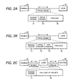
- FIGS. 2A through 2C illustrate the formats of communication frames used in the present invention
- FIG. 3A illustrates a PPPoE frame format and FIG. 3B illustrates an Ethernet frame format;
- FIG. 4 is a block diagram showing a configuration of a user terminal
- FIG. 5 illustrates a structure of and status change in a terminal management table 25 provided in the user terminal
- FIG. 6 is a block diagram showing a configuration of a packet forwarding apparatus (L2GW) according to the present invention.
- FIGS. 7A and 7B illustrate a structure of and status change in a user management table 17 provided in the L2GW;
- FIGS. 8A and 8B illustrate a structure of and status change in a port management table provided in the L2GW
- FIG. 9 illustrates a communication sequence for a PPPoE connection phase S 1 , LCP connection phase S 2 , authentication phase S 3 , and DHCP phase in the present invention
- FIG. 10 illustrates a communication sequence for an IP forwarding phase S 5 , LCP disconnection phase S 6 , and PPPoE disconnection phase S 7 in the present invention
- FIG. 11 is a flowchart illustrating an example of a PPPoE connection routine 210 to be executed by the user terminal
- FIG. 12 is a flowchart illustrating an example of a PPPoE connection routine 100 A to be executed by the L2GW;
- FIG. 13 is a flowchart illustrating an example of an LCP/DHCP connection routine 230 to be executed by the user terminal;
- FIG. 14 is a flowchart illustrating an example of an LCP connection/authentication routine 110 A to be executed by the L2GW;
- FIG. 15 is a flowchart illustrating an example of a DHCP/IP forwarding routine 130 A to be executed by the L2GW when receiving an Ethernet frame from the access network side;
- FIG. 16 is a flowchart illustrating an example of a DHCP/IP forwarding routine 130 B to be executed by the L2GW when receiving an Ethernet frame from transit network side;
- FIG. 17 is a flowchart illustrating an example of an LCP/PPPoE disconnection routine 250 to be executed by the user terminal;
- FIG. 18 is a flowchart illustrating an example of an LCP disconnection routine 110 B to be executed by the L2GW;
- FIG. 19 is a flowchart illustrating an example of a PPPoE disconnection routine 100 B to be executed by the L2GW;
- FIG. 20 shows an example of a network configuration including redundant L2GWs.
- FIG. 21 is a sequence diagram illustrating L2GW switching.
- FIG. 1 shows an example of a configuration of a communication network to which the present invention is applied.
- the communication network shown here comprises a plurality of L2SWs 50 ( 50 - 1 , 50 - n ) forming an access network and a transit network (ISP network) NW 1 to which these L2SWs 50 are connected.
- Each L2SW accommodates at least one user terminal 20 ( 20 - 1 to 20 - n ).
- the transit network (ISP network) NW 1 is connected to the Internet NW 2 via a router 60 .
- the transit network NW 1 is an L2 network for forwarding packets according to a layer 2 header.
- the transit network NW 1 includes an L2SW 51 - 1 connected to a RADIUS server 30 , an L2SW 51 - 2 connected to a DHCP server 40 , and a plurality of packet forwarding apparatus (nodes) L2GWs 10 ( 10 - 1 , 10 - 2 ).
- Each L2SW 50 forming the access network is connected to the multiple L2GWs 10 - 1 , 10 - 2 within the transit network. To each L2GW 10 , however, two or more L2SWs 50 in the access network can be connected. Each L2GW 10 is connected to a plurality of L2SWs 51 ( 51 - 1 , 51 - 2 ) within the transit network and each L2SW 51 within the transit network is connected to the Internet NW 2 via the router 60 .
- strings “xx-xx-xx-xx-xx-xx-xx” appended to the user terminals 20 , L2GWs 10 , servers 30 and 40 , and router 60 denote their MAC addresses and strings “xxx.xxx.x.x” appended to the user terminals 20 denote IP addresses assigned to these terminals.
- FIG. 2A illustrates a format of a communication frame to be communicated between a user terminal 20 and an L2GW 10 during a PPPoE connection phase S 1 and a PPPoE disconnection phase S 7 which will be described later.
- the communication frame for the PPPoE connection phase and the PPPoE disconnection phase is comprised of a variable length payload 76 including a control packet, and an Ethernet header 71 and a PPPoE header 72 added to the payload.
- FIG. 2B illustrates a format of a communication frame to be communicated between a user terminal 20 and an L2GW 10 during an LCP connection phase S 3 , an authentication phase S 4 , and an LCP disconnection phase S 6 which will be described later.
- the communication frame for these phases is comprised of a variable length payload 76 including a control packet, and an Ethernet header 71 , a PPPoE header 72 , and a PPP header 73 added to the payload.
- FIG. 2C illustrates a format of a communication frame to be transmitted and received by an L2GW 10 during a DHCP phase S 4 and an IP forwarding phase S 5 which will be described later.
- the communication frame for these phases is comprised of a variable length payload 76 and an Ethernet header 71 .
- FIG. 3A illustrates details of the Ethernet header 71 and the PPPoE header 72 of a communication frame 70 for the PPPoE phase.
- the Ethernet header 71 includes a destination MAC address 711 , a source MAC address 712 , and a protocol type 713 .
- the PPPoE header 72 includes a protocol version 721 , a type 722 , a code 723 , a session ID 724 , and a payload length 725 .
- FIG. 3B illustrates a format of a communication frame (Ethernet frame) 74 to be forwarded by an L2GW 10 during the DHCP phase S 4 and the IP forwarding phase S 5 .
- the communication frame 74 includes a variable length payload 76 and an Ethernet header 71 .
- the variable length payload 76 includes a control packet or an IP packet
- the Ethernet header 71 includes a destination MAC address 711 , a source MAC address 712 , and a protocol type 713 .
- a frame comprising a variable length payload 76 and an Ethernet header 71 , as shown in FIGS. 2C and 3B , which is controlled so as to be forwarded according to the destination MAC address specified in the Ethernet header 71 , is referred to as an Ethernet frame.
- a frame including a PPPoE header 72 as shown in FIGS. 2A , 2 B, and 3 A, which is controlled so as to be forwarded according to the session ID specified in the PPPoE header 72 , is referred to as a PPPoE frame.
- FIG. 4 is a block structural diagram showing a primary part of the user terminal 20 .
- the user terminal 20 comprises a main processor (controller) 21 for controlling operations of the terminal, a line interface 22 for connection to an L2SW 50 , a protocol processor 23 connected to the line interface 22 , a memory 24 , and an internal bus 26 .
- the user terminal 20 is equipped with a display unit serving as a user interface and an I/O unit such as a keyboard, but these elements are omitted from the drawing because they do not directly relate to operation of the present invention.
- a communication processing routine 200 and a terminal management table 25 are prepared as software relevant to the present invention.
- the terminal management table 25 stores an L2GW MAC address 251 of an L2GW to which a PPPoE session is connected, a session ID 252 , authentication result 253 , an IP address 254 assigned to a user terminal, and status 255 in communication control. Usage of the terminal management table 25 will be detailed later.
- the main processor 21 executes the communication processing routine 200 in response to a user's input operation and carries out communication control procedures for each of the PPPoE connection/disconnection phases, LCP connection/disconnection phases, DHCP phase, and IP forwarding phase, using the terminal management table 25 .
- the protocol processor 23 outputs a control packet or a data packet issued by the main processor 21 to the line interface 22 in a frame format according to the communication control phase; whereas, it passes a frame received from the line interface 22 to the main processor 21 .
- FIG. 6 is a block structural diagram of the packet forwarding apparatus (L2GW) 10 .
- the L2GW 10 comprises a plurality of user connection line interfaces 11 - 1 to 11 - n , a plurality of transit network (L2 network) line interfaces 13 - 1 to 13 - n , a protocol processor 12 , an L2GW controller 14 , an inter-processor interface 15 for connecting the protocol processor 12 and the L2GW controller 14 , and a memory 16 .
- PU 1 to PUn denote user side port numbers
- PL 1 to PLn denote L2 network side port numbers.
- a terminal connection/disconnection processing routine 100 In the memory 16 , a terminal connection/disconnection processing routine 100 , a RADIUS communication processing routine 120 , and a DHCP/IP communication processing routine 130 are prepared as software to be used by the protocol processor 12 .
- a user management table 17 and a port management table 18 are also formed in the memory 16 .
- Each table entry includes packet forwarding control information for each user terminal, in association with the user side port numbers 171 .
- the packet forwarding control information indicates the relation among a terminal MAC address 172 , a session ID 173 , and an authentication result 174 .
- the port management table 18 stores, in association with each of the L2 network side port numbers 181 , MAC addresses 182 of source apparatuses of received frames. Usage of the user management table 17 and the port management table 18 will be detailed later.
- the protocol processor 12 communicates communication frames with the user connection line interfaces 11 - 1 to 11 - n and the L2 network line interfaces 13 - 1 to 13 - n and carries out communication control procedures for the PPPoE connection/disconnection phases, LCP connection/disconnection phases, and authentication phase, with each user terminal according to the terminal connection/disconnection processing routine 100 .
- the protocol processor 12 also carries out a user authentication procedure with the RADIUS server 30 according to the communication processing routine 120 , and a DHCP phase communication procedure with the DHCP server 40 according to the communication processing routine 130 .
- the protocol processor 12 stores the MAC address 172 of the connection requesting terminal into the user management table, as illustrated in FIG. 7A .
- the protocol processor 12 stores an authentication result 174 into the user management table 17 , as illustrated in FIG. 7B .
- the protocol processor 12 In the DHCP phase and the IP forwarding phase that are carried out according to the DHCP/IP communication processing routine 130 , the protocol processor 12 refers to the user management table 17 and discards a received frame if the frame includes, as its destination address or source address, a MAC address not registered in the user management table 17 or a MAC address for which a normal authentication result is not registered in the user management table 17 . Packet forwarding control information registered in the user management table 17 is erased in the PPPoE disconnection phase.
- the L2GW controller 14 supervises the status of the protocol processor 12 and notifies the control terminal 90 of an abnormality in the protocol processor, if occurs.
- FIG. 9 illustrates a communication sequence for the PPPoE connection phase S 1 , LCP connection phase S 2 , authentication phase S 3 , and DHCP phase S 4 to be carried out in the network shown in FIG. 1 , when a user terminal 20 - 1 accommodated in the L2SW 50 - 1 accesses the Internet NW 2 .
- FIG. 10 illustrates a communication sequence for the IP forwarding phase S 5 , LCP disconnection phase S 6 , and PPPoE disconnection phase S 7 .
- description will be made about the operations of the user terminal 20 and the packet forwarding apparatus L2GW 10 according to the present invention, by referring to the communication sequences illustrated in FIGS. 9 and 10 and flowcharts provided in FIGS. 11 through 19 .
- FIG. 11 illustrates a flowchart of a PPPoE connection routine 210 to be executed by the user terminal 20 - 1 .
- the routine 210 forms a part of the communication processing routine 200 mentioned in FIG. 4 , together with an LCP/DHCP connection routine 230 which will be described in FIG. 13 and a LCP/PPPoE disconnection routine 250 which will be described in FIG. 17 .
- FIG. 12 illustrates a flowchart of a PPPoE connection routine 100 A to be executed by the L2GW 10 ( 10 - 1 , 10 - 2 ) when receiving a packet in the PPPoE connection phase.
- the routine 100 A forms a part of the terminal connection/disconnection routine 100 mentioned in FIG. 6 , together with an LCP connection/authentication routine 110 A which will be described in FIG. 14 , an LCP disconnection routine 110 B which will be described in FIG. 18 , and a PPPoE disconnection routine 100 B which will be described in FIG. 19 .
- the terminal In the case where the user terminal 20 - 1 establishes a session with the transit network NW 1 , the terminal first transmits to an access line a PPPoE frame including a PPPoE Active Discovery Initiation (PADI) packet which is a PPPoE phase starting packet, according to the PPPoE connection routine 210 (F 211 ).
- PADI PPPoE Active Discovery Initiation
- the user terminal changes the status 255 in the terminal management table 25 to PADO waiting state (F 212 ), as indicated by an entry EN( 1 ) in FIG. 5 , and waits for arrival of a packet of PPPoE phase (F 220 ).
- the PADI packet is issued to look for a packet forwarding node (L2GW) that is adaptable to a communication service desired by the user terminal 20 - 1 .
- a broadcast address is set as the destination MAC address 711 of the Ethernet header.
- the PADI packet is received by the L2SW 50 - 1 (SQ 11 ) and broadcasted to the L2GW 10 - 1 and L2GW 10 - 2 by the L2SW 50 - 1 (SQ 12 , SQ 13 ).
- each of the L2GW 10 - 1 and L2GW 10 - 2 Upon receiving a control packet (PPPoE frame) of PPPoE connection phase S 1 , each of the L2GW 10 - 1 and L2GW 10 - 2 judges the type of the received packet (F 101 ) according to the PPPoE connection routine 100 A illustrated in FIG. 12 .
- the PADI packet is received as in this example, each of the L2GW 10 - 1 and L2GW 10 - 2 checks whether the source MAC address of the received frame has been registered as a terminal MAC address 172 in the user management table 17 (F 102 ).
- each of the L2GW 10 - 1 and L2GW 10 - 2 sends back a PPPoE frame including a PPPoE Active Discovery Offer (PADO) packet to the source terminal (F 104 ).
- PADO PPPoE Active Discovery Offer
- each of the L2GW 10 - 1 and L2GW 10 - 2 clears the table entry having the source MAC address (F 103 ) and sends back the PADO packet (F 104 ).
- the PADO packets are transmitted to the terminal 20 - 1 from both the L2GW 10 - 1 and L2GW 10 - 2 (SQ 14 , SQ 15 ).
- the terminal 20 - 1 Upon receiving the PPPoE frame including the PADO packet (F 220 ), the terminal 20 - 1 judges the type of received packet (F 221 ). As in this example, when receiving the PADO packet, the terminal 20 - 1 registers the source MAC address 712 extracted from the Ethernet header into the terminal management table 25 (F 222 ). Then, the entry EN( 1 ) of the terminal management table 25 is changed into the state of an entry EN( 2 ) as shown in FIG. 5 .
- the user terminal 20 - 1 checks the status 255 in the terminal management table 25 (F 223 ). If the status 255 is PADO waiting, the user terminal changes the status 255 to PPPoE Active Discovery Session-Configuration (PADS) waiting (F 224 ), as indicated by an entry EN( 3 ) in FIG. 5 . Then, the terminal transmits a PPPoE frame including a PPPoE Active Discovery Request (PADR) packet which is a PPP session start request packet to the source of the PADO packet (F 225 ) and waits for arrival of a next packet in the PPPoE connection phase (F 220 ). If a PADO packet is received when the status 255 is not PADO waiting in the terminal management table 25 , the PADO packet is discarded (F 226 ).
- PADR PPPoE Active Discovery Request
- the terminal 20 - 1 Because the user terminal 20 - 1 receives the PADO packets from both the L2GW 10 - 1 and L2GW 10 - 2 in this example, the terminal selects one of the PADO packets received and transmits the PPPoE frame including the PADR packet to the source of the selected PADO packet. In FIG. 9 , the user terminal 20 - 1 transmits the PADR packet addressed to the L2GW 10 - 1 (SQ 16 ) which is the source of the first received PADO packet (SQ 14 ).
- the L2GW 10 - 1 Upon receiving the PPPoE frame including the PADR packet, the L2GW 10 - 1 judges the type of the received packet (F 101 ) according to the flowchart of FIG. 12 . Because the L2GW 10 - 1 receives the PADR packet (F 105 ) this time, the L2GW 10 - 1 assigns a session ID to a new PPP session requested by the PADR and adds a new table entry to the user management table 17 (F 106 ). The table entry includes the source MAC address of the received PADR packet as a terminal MAC address 172 and the assigned session ID as a session ID 173 .
- the L2GW 10 - 1 registers the new table entry into the user management table in association with the user side port number PU 1 , as illustrated in FIG. 7A . Then, the L2GW 10 - 1 generates a PADS packet in which the session ID 173 is specified and transmits a PPPoE frame including the PADS packet to the user terminal which is the source of the PADR packet (F 107 ).
- the L2GW 10 - 1 in the PADR packet waiting state receives a PPPoE connection phase packet other than the PADR packet, the received packet is discarded (F 108 ).
- the L2GW 10 - 1 exits the PPPoE connection phase S 1 by transmitting the above PADS packet (SQ 17 ).
- the user terminal 20 - 1 upon receiving the PPPoE frame including the PADS packet, judges the type of the received packet (F 221 , F 227 ) according to the PPPoE connection routine 210 . Because the received packet is a PADS this time, the user terminal 20 - 1 registers into the terminal management table 25 , as shown by an entry EN( 4 ) in FIG. 5 , the session ID specified in the PADS packet as the session ID 252 and changes the status 255 to LCP connection phase (F 228 ). After that, the user terminal 20 - 1 exits the PPPoE connection phase S 1 .
- the user terminal 20 - 1 discards the received packet (F 226 ) and waits for arrival of a next PPPoE connection phase packet (F 220 ).
- the user terminal 20 - 1 having established a PPPoE session performs LCP connection processing (F 231 ) according to the LCP/DHCP connection routine 230 illustrated in FIG. 13 .
- the L2GW 10 - 1 performs LCP connection processing (F 111 ) according to the LCP connection/authentication routine 110 A illustrated in FIG. 14 .
- the user terminal 20 - 1 transmits a link setup request packet (LCP Configure request) to the L2GW 10 - 1 with which the PPPoE session has been established (SQ 21 ).
- the L2GW 10 - 1 also transmits a link setup request packet (LCP Configure request) to the user terminal 20 - 1 with which the PPPoE session has been established (SQ 22 ), in the LCP connection processing (F 111 ).
- the user terminal 20 - 1 Upon receiving the LCP Configure request from the L2GW 10 - 1 , the user terminal 20 - 1 sends back a reply packet (LCP Configuration acknowledge) to the L2GW 10 - 1 (SQ 23 ), if the terminal can assent to all communication configuration options specified in this LCP Configure request. Similarly, upon receiving the LCP Configure request from the user terminal 20 - 1 , the L2GW 10 - 1 sends back a reply packet (LCP Configuration acknowledge) (SQ 24 ), if the L2GW can assent to all communication configuration options specified in the received LCP Configure request. In this way, by sending back the LCP Configuration acknowledges from both the L2GW 10 - 1 and the user terminal 20 - 1 connected by the PPPoE session, the LCP connection processing is completed.
- LCP Configuration acknowledge LCP Configuration acknowledge
- the user terminal 20 - 1 When the LCP connection processing (F 231 ) is completed, the user terminal 20 - 1 changes the status 255 in the terminal management table 25 into authentication phase, as indicated by an entry EN( 5 ) in FIG. 5 , transmits an authentication request packet including a terminal MAC address (or user ID) and a password (F 233 , SQ 31 in FIG. 9 ) and waits for arrival of a notification of authentication result (F 234 ).
- the L2GW 10 - 1 waits for arrival of an authentication request packet from the user terminal (F 112 ) after completing the LCP connection processing (F 111 ), as illustrated in the flowchart of FIG. 14 .
- the L2GW 10 - 1 Upon receiving the authentication request packet from the user terminal 20 - 1 , the L2GW 10 - 1 transmits a RADIUS request packet for user authentication to the RADIUS server 30 (F 113 ) according to the RADIUS communication processing routine 120 , and waits for a reply from the RADIUS server 30 (F 114 ).
- the RADIUS request packet is forwarded to the RADIUS server 30 via an L2SW 51 - 1 (SQ 32 ).
- the RADIUS server 30 checks the correspondence of the terminal MAC address (user ID) and password specified in the above RADIUS request packet based on the user information registered beforehand and sends back a response packet (RADIUS reply) indicating an authentication result to the L2GW 10 - 1 (SQ 33 ).
- the L2GW 10 - 1 Upon receiving the RADIUS reply (F 114 ), the L2GW 10 - 1 judges the authentication result (F 115 ). If the user authentication was successful, the L2GW 10 - 1 registers authentication OK as the authentication result 174 in the user management table 17 (F 116 ), as illustrated in FIG. 7B , transmits an authentication result notification packet to the user terminal 20 - 1 (F 117 , SQ 34 in FIG. 9 ), and exits the LCP connection routine 110 A.
- the authentication OK may be represented by a flag bit “ 1 ”.
- the L2GW 10 - 1 transmits an authentication reject notification packet to the user terminal 20 - 1 (F 118 ) and performs LCP disconnection processing (F 119 ). After that, the L2GW 10 - 1 transmits to the user terminal 20 - 1 a PPPoE Active Discovery Terminate (PADT) packet which is a session termination packet (F 120 ), clears the table entry for the user terminal 20 - 1 from the user management table 17 (F 121 ), and exits the LCP connection routine 110 A.
- PPPoE Active Discovery Terminate PADT
- the user terminal 20 - 1 Upon receiving the authentication result notification packet (F 234 ), the user terminal 20 - 1 judges the authentication result (F 235 ). If the authentication was successful, the user terminal 20 - 1 registers authentication OK as the authentication result 253 in the terminal management table 25 and changes the status 255 into DHCP phase (F 236 ) as shown by an entry EN( 6 ). Then, the LCP connection phase S 2 and the authentication phase S 3 are terminated and the user terminal enters the DHCP phase S 4 .
- the user terminal 20 - 1 performs LCP disconnection processing (F 237 ). After transmitting a PADT packet to the L2GW 10 - 1 (F 238 ), the user terminal clears the table entry from terminal management table 25 (F 239 ) and exits the LCP/DHCP connection routine 230 .
- the user terminal following the completion of the authentication phase S 3 , performs an NCP phase communication procedure such as IPCP negotiation with the L2GW 10 - 1 so that IP packets that are subsequently transmitted from the user terminal are forwarded across the transit network NW 1 according to the PPPoE protocol.
- NCP phase communication procedure such as IPCP negotiation with the L2GW 10 - 1 so that IP packets that are subsequently transmitted from the user terminal are forwarded across the transit network NW 1 according to the PPPoE protocol.
- a DHCP request packet for requesting IP address assignment to the DHCP server 40 (F 240 ) and waits for arrival of a DHCP acknowledge reply packet (F 241 ).
- the above DHCP request packet is transmitted in the form of Ethernet frame illustrated in FIG. 3B .
- the DHCP request packet transmitted from the user terminal 20 - 1 (SQ 41 ) is broadcasted to the L2GWs 10 - 1 and 10 - 2 by the L2SW 50 - 1 (SQ 42 , SQ 43 ).
- each of the L2GWs 10 - 1 and 10 - 2 executes a DHCP/IP communication processing routine 130 A illustrated in FIG. 15 .
- a DHCP/IP communication processing routine 130 B illustrated in FIG. 16 .
- each of the L2GWs 10 - 1 and 10 - 2 Upon receiving the Ethernet frame including the DHCP packet transmitted from the user terminal 20 - 1 , each of the L2GWs 10 - 1 and 10 - 2 extracts the source MAC address (F 131 ) from the received frame according to the routine 130 A and checks, by referring to the user management table 17 , whether a table entry having the above source MAC address has been registered and the relevant authentication result 253 indicates authentication OK (F 132 ).
- the received packet is discarded (F 137 ).
- the authentication result 253 indicates authentication OK only in the user management table 17 on the L2GW 10 - 1 (F 116 ). Therefore, the L2GW 10 - 2 that has not received the authentication request from the user terminal 20 - 1 discards the DHCP request packet (F 137 ), as illustrated by the sequence of FIG. 9 .
- the L2GW 10 - 1 After determining that the source MAC address and authentication OK has been registered in the user management table 17 , the L2GW 10 - 1 extracts the destination MAC address from the received fame (F 133 ) and checks whether the destination MAC address has been registered in association with any L2 network side port number 181 in the port management table 18 (F 134 ).
- the L2GW 10 - 1 forwards the Ethernet frame including the above DHCP request packet to an L2 network line interface 13 - j having the L2 side port number 181 which corresponds to the destination MAC address in the port management table 18 (F 135 , SQ 44 in FIG. 9 ). If the above destination MAC address is not registered in the port management table 18 , the L2GW 10 - 1 forwards the DHCP packet (Ethernet frame) to all L2 network line interfaces 13 - 1 to 13 - n (F 136 ).
- the DHCP server 40 Upon receiving the DHCP request packet, the DHCP server 40 assigns an IP address to the user terminal 20 - 1 and sends back to the L2GW 10 - 1 a response frame including a DHCP acknowledge packet in which the IP address is specified (SQ 45 ).
- the L2GW 10 - 1 Upon receiving the above response frame through the L2 network interface, the L2GW 10 - 1 extracts the source MAC address (DHCP server MAC address) from the received frame (F 141 ) and checks whether the source MAC address has been registered in the port management table 18 (F 142 ) according to the DHCP/IP communication processing routine 130 B illustrated in FIG. 16 .
- the source MAC address DHCP server MAC address
- the L2GW 10 - 1 registers the source MAC address (DHCP server MAC address) in association with the port number of the L2 network interface, through which the response frame was received, into the port management table 18 (F 143 ).
- the MAC address “00-00-87-00-00-17” of the DHCP server 40 is registered in association with the port number PLn into the port management table 18 , as illustrated in FIG. 8A .
- the L2GW 10 - 1 then extracts the destination MAC address from the received frame (F 144 ) and checks, by referring to the user management table 17 , whether a table entry having the destination MAC address has been registered and the relevant authentication result 253 indicates authentication OK (F 145 ). If authentication OK is indicted in the table entry having that MAC address, the L2GW 10 - 1 specifies the user side port number 171 from the above table entry (F 146 ) and forwards the received frame to the user connection line interface having the user side port number (F 147 , SQ 46 in FIG. 9 ).
- the L2GW 10 - 1 judges whether the destination MAC address of the received frame is a unicast address or multicast (or broadcast) address (F 148 ). If the destination MAC address is a unicast address, the L2GW 10 - 1 discards the received frame (F 149 ). Otherwise, the L2GW 10 - 1 forwards the received frame to all user connection line interfaces (FI 50 ).
- the user terminal 20 - 1 Upon receiving the response frame including the DHCP acknowledge packet (F 241 ), the user terminal 20 - 1 extracts the IP address from the DHCP acknowledge packet (F 242 ), registers the IP address 254 into the terminal management table 25 and changes the status 255 to IP forwarding phase (F 243 ), as indicated by an entry EN( 7 ) in FIG. 5 . After that, the user terminal 20 - 1 transits from the DHCP phase S 4 to the IP forwarding phase S 5 .
- the user terminal 20 - 1 transmits an IP packet in the form of Ethernet frame illustrated in FIG. 3B (SQ 51 ).
- the L2GW 10 - 1 Upon receiving the Ethernet frame including the IP packet, the L2GW 10 - 1 extracts the source MAC address from the received frame (F 131 ) and checks the terminal MAC address and the relevant authentication result (F 132 ) by referring to the user management table 17 , according to the DHCP/IP communication processing routine 130 A illustrated in FIG. 15 .
- the L2GW 10 - 1 extracts the destination MAC address from the received frame (F 133 ), specifies the L2 network side port number corresponding to the destination MAC address from the port management table 18 (F 134 ), and forwards the received frame to the L2 network line interface 13 identified with the above L2 network side port number (F 135 ).
- the L2GW 10 - 1 forwards the received frame to all L2 network line interfaces (F 136 ).
- a transmission frame (IP packet) from the user terminal 20 - 1 is forwarded to the router 60 (SQ 52 ) and forwarded from the router 60 to the destination device, e.g., a Web server on the Internet NW 2 (SQ 53 ).
- the destination device e.g., a Web server on the Internet NW 2 (SQ 53 ).
- an IP packet destined to the user terminal 20 - 1 received by the router 60 from the Internet NW 2 side (SQ 54 ), is forwarded in the form of Ethernet frame to the L2GW 10 - 1 (SQ 55 ).
- the L2GW 10 - 1 Upon receiving the Ethernet frame from the router 60 , the L2GW 10 - 1 extracts the source MAC address (the MAC address of the router 60 ) from the received frame (F 141 ) and checks whether the source MAC address has been registered in the port management table 18 (F 142 ), according to the DHCP/IP communication processing routine 130 B illustrated in FIG. 16 . If that source MAC address has not been registered, the L2GW 10 - 1 registers the source MAC address (the MAC address of the router), in association with the port number of the L2 network interface through which the Ethernet frame was received, into the port management table 18 (F 143 ).
- the MAC address “00-00-87-00-00-18” of the router 60 is registered into the port management table 18 , as illustrated in FIG. 8A .
- the L2GW 10 - 1 then extracts the destination MAC address from the received frame (F 144 ) and checks, by referring to the user management table 17 , whether a table entry having the destination MAC address has been registered and the relevant authentication result 253 is authentication OK (F 145 ). If the received frame is addressed to the user terminal 20 - 1 , the table entry having that destination MAC address has already been registered in the user management table 17 and the relevant authentication result 253 is authentication OK. Thus, the L2GW 10 - 1 specifies the user side port number 171 (F 146 ) from the table entry and forwards the received frame to the user connection line interface identified with the user side port number (F 147 , SQ 56 in FIG. 9 ).
- the L2GW 10 - 1 selectively controls the forwarding of Ethernet frames received from the user network side and the L2 network side in the IP forwarding phase, by referring to the user management table 17 .
- the L2GW 10 - 1 and the user terminal 20 - 1 communicate Keepalive packets periodically in order to monitor the operating status of the other device mutually. For example, when the L2GW 10 - 1 transmits a Keepalive request packet (SQ 61 a ) in the form of Ethernet frame periodically, destined to each terminal MAC address registered in the user management table 17 , the user terminal 20 - 1 having received the Keepalive request packet sends back, as a response packet, a Keepalive acknowledge packet to the L2GW 10 - 1 (SQ 62 a ).
- SQ 61 a Keepalive request packet
- SQ 62 a Keepalive acknowledge packet
- the L2GW 10 - 1 sends back, in response to the request packet, a Keepalive acknowledge packet to the user terminal 20 - 1 (SQ 62 b ).
- the L2GW 10 - 1 disconnects the session with the terminal, judging that the user terminal has discontinued the communication.
- FIG. 17 illustrates an LCP/PPPoE disconnection routine 250 to be executed by the user terminal 20 - 1 .
- FIG. 18 illustrates an LCP disconnection routine 110 B to be executed by the L2GW 10 - 1 when an LCP terminate request packet for requesting a link disconnection was received.
- FIG. 19 illustrates a PPPoE disconnection routine 100 B to be executed by the L2GW 10 - 1 when a PADT packet for requesting a PPPoE disconnection was received.
- the user terminal 20 - 1 and the L2GW 10 - 1 communicate control packets in the form of PPPoE frame having a PPP header as illustrated in FIG. 2B .
- the user terminal 20 - 1 transmits an LCP Terminate request packet which is a link disconnection request in LCP to the L2GW 10 - 1 (F 251 , SQ 71 in FIG. 9 ) and waits for arrival of a response packet (F 252 ), according to the LCP/PPPoE disconnection routine 250 illustrated in FIG. 17 .
- the L2GW 10 - 1 Upon receiving the LCP terminate request packet from the user terminal 20 - 1 , the L2GW 10 - 1 extracts the source MAC address (F 161 ) from the received packet and checks whether the source MAC address has been registered and the relevant authentication result is authentication OK (F 162 ) by referring to the user management table 17 , according to the LCP disconnection routine 110 B illustrated in FIG. 18 . If that source MAC address has not been registered or the relevant authentication result is not authentication OK, the L2GW 10 - 1 discards the received packet (F 165 ).
- the L2GW 10 - 1 clears the authentication result 174 from the user management table 17 (F 163 ) and sends back a reply (LCP Terminate acknowledge packet) in response to the link disconnection request to the user terminal 20 - 1 (F 164 , SQ 72 in FIG. 9 ).
- the user terminal 20 - 1 By receiving the LCP Terminate acknowledge packet (F 252 ), the user terminal 20 - 1 completes the link disconnection and enters the PPPoE disconnection phase S 7 .
- the PPPoE disconnection phase S 7 the user terminal 20 - 1 and the L2GW 10 - 1 communicate control packets in the form of PPPoE frame as illustrated in FIG. 2A .
- the user terminal 20 - 1 Having entered the PPPoE disconnection phase S 7 , the user terminal 20 - 1 transmits a PADT packet which is a PPPoE disconnection request to the L2GW 10 - 1 (F 253 , SQ 81 in FIG. 9 ). After that, the user terminal 20 - 1 checks the terminal management table 25 (F 254 ) and clears registered information, if any, from the terminal management table (F 255 ), whereby the PPPoE session is disconnected.
- the L2GW 10 - 1 upon receiving the PPPoE frame including the PADT packet from the user terminal, the L2GW 10 - 1 checks whether the source MAC address (terminal MAC address) of the received frame and the session ID have been registered in the user management table 17 (F 171 ), according to the PPPoE disconnection routine 100 B illustrated in FIG. 19 .
- the L2GW 10 - 1 clears the table entry having the above source MAC address from the user management table 17 (F 172 ). Otherwise, the L2GW 10 - 1 discards the received packet (F 173 ). Clearing the table entry for the use terminal 20 - 1 from the user management table 17 means disconnection of the PPPoE link between the L2GW 10 - 1 and the user terminal 20 - 1 .
- the user terminal 20 - 1 acquires its IP address (IPv4) from the DHCP server 40 in the above-described embodiment.
- IPv6 IP address
- each user terminal may get an IPv6 address from a DHCPv6 server, using a Router Advertisement (RA) protocol or a DHCPv6 protocol.
- RA Router Advertisement
- FIG. 20 illustrates a network portion including a terminal 20 - 1 , an L2SW 50 - 1 , and L2GWs 10 - 1 and 10 - 2 .
- a communication sequence of FIG. 21 illustrates how the user terminal 20 - 1 operates when a connection line L 10 - 1 between the L2SW 50 - 1 and the L2GW 10 - 1 has failed, as marked with x in FIG. 20 .
- the communication sequence indicated here is also applicable for a case where the connection line L 10 - 1 is normal, but the L2GW 10 - 1 has malfunctioned.
- the user terminal 20 - 1 When a fault occurs in the connection line L 10 - 1 or the L2GW 10 - 1 , the user terminal 20 - 1 cannot receive a Keepalive acknowledge packet from the L2GW 10 - 1 within a predetermined time after the user terminal 20 - 1 transmits a Keepalive request packet to the L2GW 10 - 1 (SQ 61 ( 1 )). If there is no response from the L2GW 10 - 1 , the user terminal 20 - 1 retransmits a Keepalive request packet (SQ 61 ( 2 )).
- the user terminal 20 - 1 When finding that a response packet from the L2GW 10 - 1 cannot be received in spite of retransmission of the Keepalive request packet, the user terminal 20 - 1 transmits a PADT packet which is a PPPoE disconnection request to the L2GW 10 - 1 (SQ 81 ) and once clears the terminal management table. After that, the user terminal 20 - 1 broadcasts a PADI packet which is a PPPoE start packet in order to look for a new L2GW to be connected instead of the L2GW 10 - 1 (SQ 111 ).
- the PADI packet is forwarded to the L2GWs 10 - 1 and 10 - 2 by the L2SW 50 - 1 (SQ 112 , S 113 ).
- the user terminal 20 - 1 can receive a PADO packet from the L2GW 10 - 2 (SQ 113 ).
- the user terminal 20 - 1 transmits a PADR packet to the L2GW 10 - 2 , the source of the PADO packet (SQ 116 ), according to the PPPoE connection routine 210 as described with FIG. 11 .
- each user terminal can access the Internet even when one of L2GWs has failed, by performing communication procedures for the PPPoE phase, LCP phase, authentication phase, and DHCP phase with another L2GW in normal state.
- a user terminal having been authenticated in the user authentication phase acquires an IP address through the DHCP phase communication procedure and communicates IP packets in the form of Ethernet frame which does not require a PPPoE header and a PPP header in the IP forwarding phase, the efficiency of data transmission over the access lines and the transit network can be improved.
- user terminals can perform IPv6 communication in the IP forwarding phase by acquiring an IPv6 prefix, using, e.g., a Dynamic Host Configuration Protocol for Internet Protocol Version6 (DHCPv6) or the like.
- DHCPv6 Dynamic Host Configuration Protocol for Internet Protocol Version6
- a plurality of user terminals 20 are accommodated to the L2SWs 50 through individual access lines, respectively.
- a Passive Optical Network may be applied as the access network.
- an Optical Line Terminal located in a central office and a plurality of Optical Network Units (ONUs) for subscriber connections are connected through an optical network in which an optical fiber connected to the OLT diverges at an optical splitter into a plurality of brunch fibers to be connected to each ONU.
- each of user terminals 20 is connected to the OLTs via ONU located at subscriber home and an optical fiber.
- the OLTs undertake packet forwarding in each phase performed by the L2SWs 50 as described for FIG. 9 .
- the PON may be applied to a network section between the terminals and the L2SWs 50 which are still used.
Landscapes
- Engineering & Computer Science (AREA)
- Computer Networks & Wireless Communication (AREA)
- Signal Processing (AREA)
- Computer Hardware Design (AREA)
- Computer Security & Cryptography (AREA)
- Computing Systems (AREA)
- General Engineering & Computer Science (AREA)
- Data Exchanges In Wide-Area Networks (AREA)
- Small-Scale Networks (AREA)
Abstract
Description
Claims (13)
Applications Claiming Priority (2)
| Application Number | Priority Date | Filing Date | Title |
|---|---|---|---|
| JP2006-141455 | 2006-05-22 | ||
| JP2006141455A JP4791252B2 (en) | 2006-05-22 | 2006-05-22 | Packet transfer device, packet transfer system, user terminal device, and packet transfer method |
Publications (2)
| Publication Number | Publication Date |
|---|---|
| US20070274290A1 US20070274290A1 (en) | 2007-11-29 |
| US7733859B2 true US7733859B2 (en) | 2010-06-08 |
Family
ID=38749411
Family Applications (1)
| Application Number | Title | Priority Date | Filing Date |
|---|---|---|---|
| US11/751,158 Expired - Fee Related US7733859B2 (en) | 2006-05-22 | 2007-05-21 | Apparatus and method for packet forwarding in layer 2 network |
Country Status (3)
| Country | Link |
|---|---|
| US (1) | US7733859B2 (en) |
| JP (1) | JP4791252B2 (en) |
| CN (1) | CN101079887B (en) |
Cited By (14)
| Publication number | Priority date | Publication date | Assignee | Title |
|---|---|---|---|---|
| US20090046615A1 (en) * | 2007-08-17 | 2009-02-19 | Hitachi Communication Technologies, Ltd. | Network system, network apparatus and transfer apparatus |
| US9264295B1 (en) | 2012-03-02 | 2016-02-16 | Big Switch Networks, Inc. | Systems and methods for forwarding broadcast network packets with a controller |
| US9444620B1 (en) * | 2010-06-24 | 2016-09-13 | F5 Networks, Inc. | Methods for binding a session identifier to machine-specific identifiers and systems thereof |
| US20180302334A1 (en) * | 2015-05-08 | 2018-10-18 | Ooma, Inc. | Communications Network Failure Detection and Remediation |
| US10469556B2 (en) | 2007-05-31 | 2019-11-05 | Ooma, Inc. | System and method for providing audio cues in operation of a VoIP service |
| US10553098B2 (en) | 2014-05-20 | 2020-02-04 | Ooma, Inc. | Appliance device integration with alarm systems |
| US10728386B2 (en) | 2013-09-23 | 2020-07-28 | Ooma, Inc. | Identifying and filtering incoming telephone calls to enhance privacy |
| US10769931B2 (en) | 2014-05-20 | 2020-09-08 | Ooma, Inc. | Network jamming detection and remediation |
| US10818158B2 (en) | 2014-05-20 | 2020-10-27 | Ooma, Inc. | Security monitoring and control |
| US10911368B2 (en) | 2015-05-08 | 2021-02-02 | Ooma, Inc. | Gateway address spoofing for alternate network utilization |
| US11032211B2 (en) | 2015-05-08 | 2021-06-08 | Ooma, Inc. | Communications hub |
| US11063758B1 (en) | 2016-11-01 | 2021-07-13 | F5 Networks, Inc. | Methods for facilitating cipher selection and devices thereof |
| US11171875B2 (en) | 2015-05-08 | 2021-11-09 | Ooma, Inc. | Systems and methods of communications network failure detection and remediation utilizing link probes |
| US11316974B2 (en) | 2014-07-09 | 2022-04-26 | Ooma, Inc. | Cloud-based assistive services for use in telecommunications and on premise devices |
Families Citing this family (28)
| Publication number | Priority date | Publication date | Assignee | Title |
|---|---|---|---|---|
| US7835297B2 (en) * | 2007-06-29 | 2010-11-16 | World Wide Packets, Inc. | Determining the state of a tunnel with respect to a control protocol |
| US20090073990A1 (en) * | 2007-09-14 | 2009-03-19 | Hewlett-Packard Development Company, L.P. | Method of replacing a router in a layer 3 network |
| US8627447B1 (en) * | 2007-09-18 | 2014-01-07 | Juniper Networks, Inc. | Provisioning layer three access for agentless devices |
| US7778203B2 (en) * | 2008-02-01 | 2010-08-17 | Microsoft Corporation | On-demand MAC address lookup |
| CN101873515B (en) * | 2009-04-21 | 2013-12-04 | 华为技术有限公司 | IPV6 message transmission method, system and device of passive optical network |
| KR101276798B1 (en) * | 2009-12-10 | 2013-06-19 | 한국전자통신연구원 | System and method for offering communication provider selection service in distribution network |
| CN101771612B (en) * | 2010-01-13 | 2012-07-04 | 华为技术有限公司 | Tunnel establishing method, equipment and network system |
| CN101808103A (en) * | 2010-04-26 | 2010-08-18 | 中兴通讯股份有限公司 | Device and method for realizing point to point protocol data service disconnection |
| EP2589188B1 (en) * | 2010-06-29 | 2020-04-22 | Huawei Technologies Co., Ltd. | Asymmetric network address encapsulation |
| KR20120057172A (en) * | 2010-11-26 | 2012-06-05 | 한국전자통신연구원 | Access point, L2 switch and method for supporting mobile multicast handover using the access point and the L2 switch |
| US9178619B2 (en) * | 2011-06-08 | 2015-11-03 | Electronics And Telecommunications Research Institute | Passive optical network (PON)-based system and method for providing handover among optical network terminals (ONTs) |
| JP5760736B2 (en) * | 2011-06-22 | 2015-08-12 | 富士通株式会社 | Communication device |
| US20130304887A1 (en) * | 2012-05-11 | 2013-11-14 | Qualcomm Incorporated | Systems and methods for domain name system querying |
| CN103873434B (en) * | 2012-12-10 | 2017-12-12 | 台众计算机股份有限公司 | The method used to identify the occurrence of events at the site |
| CN104125191B (en) * | 2013-04-23 | 2017-09-26 | 华为技术有限公司 | Processing method, equipment and the system of point-to-point protocol based on Ethernet |
| CN105101195B (en) * | 2014-04-30 | 2018-11-30 | 华为技术有限公司 | The control method and device of network admittance |
| WO2015189876A1 (en) * | 2014-06-13 | 2015-12-17 | 三菱電機株式会社 | Bridge apparatus |
| US20160112311A1 (en) * | 2014-10-20 | 2016-04-21 | Gainspan Corporation | Enhanced connectivity to end devices via access points of wireless local area networks (wlan) |
| CN104539580B (en) * | 2014-12-02 | 2017-10-31 | 重庆旭贤科技发展有限公司 | The route control method independently selected based on the PPPoE users for shunting gateway |
| WO2016121293A1 (en) | 2015-01-28 | 2016-08-04 | 日本電気株式会社 | Network relay device, gateway redundancy system, program, and redundancy method |
| KR102234210B1 (en) * | 2015-07-24 | 2021-03-30 | 현대자동차주식회사 | Security method for ethernet based network |
| US9979557B2 (en) * | 2015-08-10 | 2018-05-22 | Hughes Network Systems, Llc | Carrier grade Ethernet layer 2 over layer 3 satellite backbones (L2oL3SB) |
| CN106685847B (en) | 2015-11-06 | 2020-01-17 | 华为技术有限公司 | A message processing method, device and device |
| CN107070757B (en) * | 2017-03-06 | 2020-03-27 | 北京安博通科技股份有限公司 | Method and device for establishing network connection |
| US11012257B2 (en) * | 2017-03-16 | 2021-05-18 | Sumitomo Electric Industries, Ltd. | Home side device and method of clearing management table |
| CN106936718B (en) * | 2017-03-30 | 2019-12-13 | 网宿科技股份有限公司 | PPPoE packet transmission method and PPPoE server |
| EP3993352A1 (en) * | 2020-10-29 | 2022-05-04 | Juniper Networks, Inc. | Supporting dynamic host configuration protocol-based customer premises equipment in fifth generation wireline and wireless convergence |
| JP7608221B2 (en) * | 2021-03-11 | 2025-01-06 | 三菱電機株式会社 | Communication Equipment |
Citations (6)
| Publication number | Priority date | Publication date | Assignee | Title |
|---|---|---|---|---|
| JP2003060675A (en) | 2001-08-15 | 2003-02-28 | Fujitsu Ltd | Communication method, communication system, user terminal device, and communication connection program |
| JP2003224577A (en) | 2001-10-05 | 2003-08-08 | Toyo Commun Equip Co Ltd | Internet relay device |
| US20030182434A1 (en) * | 2002-03-01 | 2003-09-25 | Minoru Ogushi | Network system |
| JP2004304574A (en) | 2003-03-31 | 2004-10-28 | Fujitsu Ltd | Communication device |
| US20050041671A1 (en) * | 2003-07-28 | 2005-02-24 | Naoya Ikeda | Network system and an interworking apparatus |
| US7409451B1 (en) * | 2003-05-30 | 2008-08-05 | Aol Llc, A Delaware Limited Liability Company | Switching between connectivity types to maintain connectivity |
Family Cites Families (4)
| Publication number | Priority date | Publication date | Assignee | Title |
|---|---|---|---|---|
| CN1549546B (en) * | 2003-05-09 | 2011-06-22 | 中兴通讯股份有限公司 | Apparatus and method for realizing PPPOE user dynamic obtaining IP address utilizing DHCP protocol |
| CN1553674A (en) * | 2003-05-26 | 2004-12-08 | 广东省电信有限公司科学技术研究院 | Method for wideband connection server to obtain port numbers of its uers |
| CN100370768C (en) * | 2003-07-07 | 2008-02-20 | 华为技术有限公司 | Method to trigger the allocation of IP addresses to users |
| KR100590875B1 (en) * | 2004-01-20 | 2006-06-19 | 삼성전자주식회사 | A digital subscriber line modem with a P.P.S.Spoofing server and its system, and a method for accessing the Internet using the P.P.P. |
-
2006
- 2006-05-22 JP JP2006141455A patent/JP4791252B2/en not_active Expired - Fee Related
-
2007
- 2007-05-21 US US11/751,158 patent/US7733859B2/en not_active Expired - Fee Related
- 2007-05-22 CN CN2007101050332A patent/CN101079887B/en not_active Expired - Fee Related
Patent Citations (6)
| Publication number | Priority date | Publication date | Assignee | Title |
|---|---|---|---|---|
| JP2003060675A (en) | 2001-08-15 | 2003-02-28 | Fujitsu Ltd | Communication method, communication system, user terminal device, and communication connection program |
| JP2003224577A (en) | 2001-10-05 | 2003-08-08 | Toyo Commun Equip Co Ltd | Internet relay device |
| US20030182434A1 (en) * | 2002-03-01 | 2003-09-25 | Minoru Ogushi | Network system |
| JP2004304574A (en) | 2003-03-31 | 2004-10-28 | Fujitsu Ltd | Communication device |
| US7409451B1 (en) * | 2003-05-30 | 2008-08-05 | Aol Llc, A Delaware Limited Liability Company | Switching between connectivity types to maintain connectivity |
| US20050041671A1 (en) * | 2003-07-28 | 2005-02-24 | Naoya Ikeda | Network system and an interworking apparatus |
Cited By (25)
| Publication number | Priority date | Publication date | Assignee | Title |
|---|---|---|---|---|
| US10469556B2 (en) | 2007-05-31 | 2019-11-05 | Ooma, Inc. | System and method for providing audio cues in operation of a VoIP service |
| US8396019B2 (en) * | 2007-08-17 | 2013-03-12 | Hitachi, Ltd. | Network system, network apparatus and transfer apparatus |
| US20090046615A1 (en) * | 2007-08-17 | 2009-02-19 | Hitachi Communication Technologies, Ltd. | Network system, network apparatus and transfer apparatus |
| US9444620B1 (en) * | 2010-06-24 | 2016-09-13 | F5 Networks, Inc. | Methods for binding a session identifier to machine-specific identifiers and systems thereof |
| US9264295B1 (en) | 2012-03-02 | 2016-02-16 | Big Switch Networks, Inc. | Systems and methods for forwarding broadcast network packets with a controller |
| US10728386B2 (en) | 2013-09-23 | 2020-07-28 | Ooma, Inc. | Identifying and filtering incoming telephone calls to enhance privacy |
| US10553098B2 (en) | 2014-05-20 | 2020-02-04 | Ooma, Inc. | Appliance device integration with alarm systems |
| US11094185B2 (en) | 2014-05-20 | 2021-08-17 | Ooma, Inc. | Community security monitoring and control |
| US10769931B2 (en) | 2014-05-20 | 2020-09-08 | Ooma, Inc. | Network jamming detection and remediation |
| US11495117B2 (en) | 2014-05-20 | 2022-11-08 | Ooma, Inc. | Security monitoring and control |
| US10818158B2 (en) | 2014-05-20 | 2020-10-27 | Ooma, Inc. | Security monitoring and control |
| US11763663B2 (en) | 2014-05-20 | 2023-09-19 | Ooma, Inc. | Community security monitoring and control |
| US11250687B2 (en) | 2014-05-20 | 2022-02-15 | Ooma, Inc. | Network jamming detection and remediation |
| US11151862B2 (en) | 2014-05-20 | 2021-10-19 | Ooma, Inc. | Security monitoring and control utilizing DECT devices |
| US11315405B2 (en) | 2014-07-09 | 2022-04-26 | Ooma, Inc. | Systems and methods for provisioning appliance devices |
| US11316974B2 (en) | 2014-07-09 | 2022-04-26 | Ooma, Inc. | Cloud-based assistive services for use in telecommunications and on premise devices |
| US11330100B2 (en) | 2014-07-09 | 2022-05-10 | Ooma, Inc. | Server based intelligent personal assistant services |
| US12190702B2 (en) | 2014-07-09 | 2025-01-07 | Ooma, Inc. | Systems and methods for provisioning appliance devices in response to a panic signal |
| US11171875B2 (en) | 2015-05-08 | 2021-11-09 | Ooma, Inc. | Systems and methods of communications network failure detection and remediation utilizing link probes |
| US11032211B2 (en) | 2015-05-08 | 2021-06-08 | Ooma, Inc. | Communications hub |
| US10911368B2 (en) | 2015-05-08 | 2021-02-02 | Ooma, Inc. | Gateway address spoofing for alternate network utilization |
| US10771396B2 (en) * | 2015-05-08 | 2020-09-08 | Ooma, Inc. | Communications network failure detection and remediation |
| US11646974B2 (en) | 2015-05-08 | 2023-05-09 | Ooma, Inc. | Systems and methods for end point data communications anonymization for a communications hub |
| US20180302334A1 (en) * | 2015-05-08 | 2018-10-18 | Ooma, Inc. | Communications Network Failure Detection and Remediation |
| US11063758B1 (en) | 2016-11-01 | 2021-07-13 | F5 Networks, Inc. | Methods for facilitating cipher selection and devices thereof |
Also Published As
| Publication number | Publication date |
|---|---|
| JP4791252B2 (en) | 2011-10-12 |
| CN101079887A (en) | 2007-11-28 |
| JP2007312289A (en) | 2007-11-29 |
| US20070274290A1 (en) | 2007-11-29 |
| CN101079887B (en) | 2010-09-29 |
Similar Documents
| Publication | Publication Date | Title |
|---|---|---|
| US7733859B2 (en) | Apparatus and method for packet forwarding in layer 2 network | |
| JP4680866B2 (en) | Packet transfer device with gateway load balancing function | |
| US7835355B2 (en) | Packet forwarding apparatus having gateway selecting function | |
| JP4881829B2 (en) | Packet forwarding system | |
| JP3920305B1 (en) | Packet transfer device | |
| US7792972B2 (en) | Packet forwarding control method and packet forwarding apparatus | |
| JP4537357B2 (en) | Dynamic construction of VLAN interface based on subscriber information string | |
| US7469298B2 (en) | Method and system for enabling layer 2 transmission of IP data frame between user terminal and service provider | |
| CN101547383B (en) | Access authentication method, access authentication system and related equipment | |
| WO2008017268A1 (en) | Access network system, access equipment, arp proxy method and ip bridging forwarding method | |
| US20050157722A1 (en) | Access user management system and access user management apparatus | |
| US20070195804A1 (en) | Ppp gateway apparatus for connecting ppp clients to l2sw | |
| WO2008024226A1 (en) | Method and system for inter working a point-to-point link and a lan service | |
| JP3757863B2 (en) | Access network equipment | |
| CN100435520C (en) | Methods of choosing services offered by different network service providers | |
| JP2009267987A (en) | Station-side apparatus, pon system and home gateway device | |
| JP5261432B2 (en) | Communication system, packet transfer method, network switching apparatus, access control apparatus, and program | |
| JP4621259B2 (en) | Packet transfer control method | |
| CN101365238B (en) | Session converting method and apparatus | |
| JP4143663B2 (en) | Network system | |
| JP4817797B2 (en) | PPPoE bridge device and PPPoE session disconnection method | |
| JP3990385B2 (en) | LAN connection device and LAN connection method | |
| JP4755879B2 (en) | PPPoE client apparatus and PPPoE session disconnection method |
Legal Events
| Date | Code | Title | Description |
|---|---|---|---|
| AS | Assignment |
Owner name: HITACHI COMMUNICATION TECHNOLOGIES, LTD., JAPAN Free format text: ASSIGNMENT OF ASSIGNORS INTEREST;ASSIGNORS:TAKAHASHI, TADASHI;MIYATA, HIROAKI;YOKOYAMA, TAKASHI;AND OTHERS;REEL/FRAME:022818/0742 Effective date: 20070523 Owner name: HITACHI COMMUNICATION TECHNOLOGIES, LTD.,JAPAN Free format text: ASSIGNMENT OF ASSIGNORS INTEREST;ASSIGNORS:TAKAHASHI, TADASHI;MIYATA, HIROAKI;YOKOYAMA, TAKASHI;AND OTHERS;REEL/FRAME:022818/0742 Effective date: 20070523 |
|
| AS | Assignment |
Owner name: HITACHI, LTD.,JAPAN Free format text: MERGER;ASSIGNOR:HITACHI COMMUNICATION TECHNOLOGIES, LTD.;REEL/FRAME:023741/0708 Effective date: 20090701 Owner name: HITACHI, LTD., JAPAN Free format text: MERGER;ASSIGNOR:HITACHI COMMUNICATION TECHNOLOGIES, LTD.;REEL/FRAME:023741/0708 Effective date: 20090701 |
|
| FEPP | Fee payment procedure |
Free format text: PAYOR NUMBER ASSIGNED (ORIGINAL EVENT CODE: ASPN); ENTITY STATUS OF PATENT OWNER: LARGE ENTITY |
|
| FPAY | Fee payment |
Year of fee payment: 4 |
|
| FEPP | Fee payment procedure |
Free format text: MAINTENANCE FEE REMINDER MAILED (ORIGINAL EVENT CODE: REM.) |
|
| LAPS | Lapse for failure to pay maintenance fees |
Free format text: PATENT EXPIRED FOR FAILURE TO PAY MAINTENANCE FEES (ORIGINAL EVENT CODE: EXP.) |
|
| STCH | Information on status: patent discontinuation |
Free format text: PATENT EXPIRED DUE TO NONPAYMENT OF MAINTENANCE FEES UNDER 37 CFR 1.362 |
|
| FP | Lapsed due to failure to pay maintenance fee |
Effective date: 20180608 |