JP4164080B2 - Bicycle headset structure - Google Patents
Bicycle headset structure Download PDFInfo
- Publication number
- JP4164080B2 JP4164080B2 JP2005136891A JP2005136891A JP4164080B2 JP 4164080 B2 JP4164080 B2 JP 4164080B2 JP 2005136891 A JP2005136891 A JP 2005136891A JP 2005136891 A JP2005136891 A JP 2005136891A JP 4164080 B2 JP4164080 B2 JP 4164080B2
- Authority
- JP
- Japan
- Prior art keywords
- bicycle
- steering tube
- end opening
- tubular spacer
- spacer member
- Prior art date
- Legal status (The legal status is an assumption and is not a legal conclusion. Google has not performed a legal analysis and makes no representation as to the accuracy of the status listed.)
- Active
Links
Images


Classifications
-
- B—PERFORMING OPERATIONS; TRANSPORTING
- B62—LAND VEHICLES FOR TRAVELLING OTHERWISE THAN ON RAILS
- B62K—CYCLES; CYCLE FRAMES; CYCLE STEERING DEVICES; RIDER-OPERATED TERMINAL CONTROLS SPECIALLY ADAPTED FOR CYCLES; CYCLE AXLE SUSPENSIONS; CYCLE SIDE-CARS, FORECARS, OR THE LIKE
- B62K21/00—Steering devices
- B62K21/12—Handlebars; Handlebar stems
-
- B—PERFORMING OPERATIONS; TRANSPORTING
- B62—LAND VEHICLES FOR TRAVELLING OTHERWISE THAN ON RAILS
- B62J—CYCLE SADDLES OR SEATS; AUXILIARY DEVICES OR ACCESSORIES SPECIALLY ADAPTED TO CYCLES AND NOT OTHERWISE PROVIDED FOR, e.g. ARTICLE CARRIERS OR CYCLE PROTECTORS
- B62J11/00—Supporting arrangements specially adapted for fastening specific devices to cycles, e.g. supports for attaching maps
- B62J11/10—Supporting arrangements specially adapted for fastening specific devices to cycles, e.g. supports for attaching maps for mechanical cables, hoses, pipes or electric wires, e.g. cable guides
- B62J11/19—Supporting arrangements specially adapted for fastening specific devices to cycles, e.g. supports for attaching maps for mechanical cables, hoses, pipes or electric wires, e.g. cable guides specially adapted for electric wires
-
- B—PERFORMING OPERATIONS; TRANSPORTING
- B62—LAND VEHICLES FOR TRAVELLING OTHERWISE THAN ON RAILS
- B62J—CYCLE SADDLES OR SEATS; AUXILIARY DEVICES OR ACCESSORIES SPECIALLY ADAPTED TO CYCLES AND NOT OTHERWISE PROVIDED FOR, e.g. ARTICLE CARRIERS OR CYCLE PROTECTORS
- B62J45/00—Electrical equipment arrangements specially adapted for use as accessories on cycles, not otherwise provided for
- B62J45/20—Cycle computers as cycle accessories
-
- B—PERFORMING OPERATIONS; TRANSPORTING
- B62—LAND VEHICLES FOR TRAVELLING OTHERWISE THAN ON RAILS
- B62K—CYCLES; CYCLE FRAMES; CYCLE STEERING DEVICES; RIDER-OPERATED TERMINAL CONTROLS SPECIALLY ADAPTED FOR CYCLES; CYCLE AXLE SUSPENSIONS; CYCLE SIDE-CARS, FORECARS, OR THE LIKE
- B62K19/00—Cycle frames
- B62K19/30—Frame parts shaped to receive other cycle parts or accessories
- B62K19/40—Frame parts shaped to receive other cycle parts or accessories for attaching accessories, e.g. article carriers, lamps
-
- B—PERFORMING OPERATIONS; TRANSPORTING
- B62—LAND VEHICLES FOR TRAVELLING OTHERWISE THAN ON RAILS
- B62K—CYCLES; CYCLE FRAMES; CYCLE STEERING DEVICES; RIDER-OPERATED TERMINAL CONTROLS SPECIALLY ADAPTED FOR CYCLES; CYCLE AXLE SUSPENSIONS; CYCLE SIDE-CARS, FORECARS, OR THE LIKE
- B62K21/00—Steering devices
- B62K21/06—Bearings specially adapted for steering heads
-
- B—PERFORMING OPERATIONS; TRANSPORTING
- B62—LAND VEHICLES FOR TRAVELLING OTHERWISE THAN ON RAILS
- B62M—RIDER PROPULSION OF WHEELED VEHICLES OR SLEDGES; POWERED PROPULSION OF SLEDGES OR SINGLE-TRACK CYCLES; TRANSMISSIONS SPECIALLY ADAPTED FOR SUCH VEHICLES
- B62M25/00—Actuators for gearing speed-change mechanisms specially adapted for cycles
- B62M25/02—Actuators for gearing speed-change mechanisms specially adapted for cycles with mechanical transmitting systems, e.g. cables, levers
-
- B—PERFORMING OPERATIONS; TRANSPORTING
- B62—LAND VEHICLES FOR TRAVELLING OTHERWISE THAN ON RAILS
- B62M—RIDER PROPULSION OF WHEELED VEHICLES OR SLEDGES; POWERED PROPULSION OF SLEDGES OR SINGLE-TRACK CYCLES; TRANSMISSIONS SPECIALLY ADAPTED FOR SUCH VEHICLES
- B62M25/00—Actuators for gearing speed-change mechanisms specially adapted for cycles
- B62M25/08—Actuators for gearing speed-change mechanisms specially adapted for cycles with electrical or fluid transmitting systems
Description
本発明は、自転車のヘッドセット構造に関する。より詳細には、本発明は、ハンドルバー取付部材から自転車フレーム部へのワイヤリング経路を提供するよう構成され、これにより、ワイヤが自転車フレームのヘッドチューブを通って隠れるように延びることができる自転車用ヘッドセット構造に関する。 The present invention relates to a bicycle headset structure. More particularly, the present invention is configured for a bicycle that is configured to provide a wiring path from a handlebar mounting member to a bicycle frame portion so that the wire can be hidden through the head tube of the bicycle frame. It relates to a headset structure.
自転車に乗ることは、移動の手段であるととともに、レクレーションの形態としてもますます人気が高まっている。また、自転車に乗ることは、プロ、アマを問わず、競技スポーツとしても人気が高い。レクレーション、移動、競技の用途に関わらず、自転車産業において、種々の自転車部品は、自転車用フレームと同様に、常に改良が続けられている。 Riding a bicycle is not only a means of movement, but also an increasingly popular form of recreation. Bicycling is a popular sport for both professionals and amateurs. Regardless of recreational, mobile, or competitive applications, in the bicycle industry, various bicycle components, as well as bicycle frames, are constantly being improved.
近年、ライダーにとって、ライディングを簡単に、また、より楽しいものとするために、自転車には電気部品が装備されてきている。ある自転車はコンピュータ制御部品を装備している。たとえば、サイクルコンピュータあるいは制御ユニットによってライディングコンディションに応じて自動的に調整される自動シフトユニットを備える新しい自転車も数多くある。また、ある自転車は、サイクルコンピュータあるいは制御ユニットによってライディングコンディションに応じて自動的に調整される自動制御サスペンションを備えている。
したがって、電気部品を有するこれらの自転車は、種々の電気部品を制御する制御装置及び種々の電気部品に電力を供給する1つ以上のバッテリーを装備する必要がある。残念ながら、これらの電子部品をすべて装着してライダーが電子部品にアクセスできるようするには、自転車フレーム上のスペースには限りがある。つまり、これらの電子部品は、ハンドルバーなどの自転車の特定領域に配置されることから、このことが電子部品の装着領域をさらに制限する。また、電子部品を、外見よく、使いやすいような方法で装着することが望まれる。そこで、ワイヤが自転車の動作に干渉せず、ワイヤが自転車の外観を損ねない方法で、電子部品を装着することが望ましい。 Therefore, these bicycles with electrical components need to be equipped with a controller that controls the various electrical components and one or more batteries that power the various electrical components. Unfortunately, there is limited space on the bicycle frame to mount all of these electronic components and allow riders access to the electronic components. That is, since these electronic components are arranged in a specific area of the bicycle such as a handlebar, this further restricts the mounting area of the electronic components. In addition, it is desirable to mount the electronic component in a manner that looks good and is easy to use. Therefore, it is desirable to mount the electronic component in such a way that the wire does not interfere with the operation of the bicycle and the wire does not impair the appearance of the bicycle.
以上の点から、本開示によって、この技術分野において、自転車用ヘッドセット構造の改良に対するニーズがあることが明らかにされる。本発明は、このニーズと同様に、本開示から、当業者に対して、明らかにされる他のニーズに対してもなされたものである。 In view of the above, the present disclosure clarifies that there is a need for an improved bicycle headset structure in this technical field. The present invention, as well as this need, has been made for other needs that will be apparent to those skilled in the art from this disclosure.
本発明の目的は、ハンドル領域に装着される部品から自転車の他の部分に装着される部品へワイヤを通す自転車フレームのヘッドチューブを通る、邪魔にならない通路あるいは経路を設けるよう構成される自転車用ヘッドセットを提供することにある。 An object of the present invention is for a bicycle that is configured to provide an unobstructed passage or path through the head tube of a bicycle frame that passes wires from a part mounted on the handle area to a part mounted on another part of the bicycle. To provide a headset.
本発明の他の目的は、製造に比較的コストがかからず、比較的簡単に組み込むことができる自転車用ヘッドセット構造を提供することにある。 Another object of the present invention is to provide a bicycle headset structure that is relatively inexpensive to manufacture and can be assembled relatively easily.
以上の目的は、簡潔には、ハンドルバー取付部材と、管状スペーサ部材とを備える自転車用ヘッドセット構造を提供することによって達成できる。ハンドルバー取付部材は、自転車用ハンドルバーを固定するよう構成されるハンドルバー装着部と、自転車用ステアリングチューブを固定するよう構成されるステアリングチューブ取付部とを備え、ハンドルバー装着部とステアリングチューブ取付部との間にワイヤリング通路が延びている。管状スペーサ部材は、上端開口部を有する第1端部と、下端開口部を有する第2端部と、第1端部と第2端部との間に延びるワイヤリング経路と、上端開口部と下端開口部との間に軸方向に延びる軸方向通路とを有し、軸方向通路は自転車用ステアリングチューブを収容可能である。そして、ワイヤリング経路は、ハンドルバー取付部材及び管状スペーサ部材が自転車用ステアリングチューブに取り付けられたとき、ハンドルバー取付部材のワイヤリング通路と連通する。 The above objects can be achieved simply by providing a bicycle headset structure including a handlebar mounting member and a tubular spacer member. The handlebar mounting member includes a handlebar mounting portion configured to fix the bicycle handlebar and a steering tube mounting portion configured to fix the bicycle steering tube. The handlebar mounting portion and the steering tube mounting are provided. A wiring passage extends between the two portions. The tubular spacer member includes a first end having an upper end opening, a second end having a lower end opening, a wiring path extending between the first end and the second end, an upper end opening and a lower end. An axial passage extending in the axial direction is formed between the opening portion and the axial passage can accommodate a bicycle steering tube. The wiring path communicates with the wiring path of the handlebar mounting member when the handlebar mounting member and the tubular spacer member are mounted on the bicycle steering tube.
以上の目的は、また、簡潔には、ハンドルバー取付部材の下に配置される自転車用ヘッドセット構造において使用される管状スペーサ部材を提供することによって達成できる。管状スペーサ部材は、基本的に、第1端部と、第2端部と、中央通路と、ワイヤリング経路とを備える。第1端部は上端開口部を有する。第2端部は下端開口部を有する。中央通路は、上端開口部と下端開口部との間に軸方向に延び、自転車用ステアリングチューブを収容可能である。ワイヤリング経路は、上端開口部及び下端開口部の一方から上端開口部及び下端開口部の他方へ向かって延びる。そして、ワイヤリング経路は、管状スペーサ部材が自転車用ステアリングチューブに取り付けられるとき、自転車用ステアリングチューブの外周面の外側に空間を形成するように構成されている。 The above objects can also be achieved, simply by providing a tubular spacer member for use in a bicycle headset structure that is disposed under a handlebar mounting member. The tubular spacer member basically includes a first end, a second end, a central passage, and a wiring path. The first end has an upper end opening. The second end has a lower end opening. The central passage extends in the axial direction between the upper end opening and the lower end opening, and can accommodate a bicycle steering tube. The wiring path extends from one of the upper end opening and the lower end opening toward the other of the upper end opening and the lower end opening. The wiring path is configured to form a space outside the outer peripheral surface of the bicycle steering tube when the tubular spacer member is attached to the bicycle steering tube.
以上のような本発明では、ハンドル領域に装着される部品から自転車の他の部分に装着される部品へワイヤを通す自転車フレームのヘッドチューブを通る、邪魔にならない通路あるいは経路を有する自転車用ヘッドセットを得ることができる。また、製造に比較的コストがかからず、比較的簡単に組み込むことができる自転車用ヘッドセット構造を得ることができる。 In the present invention as described above, a bicycle headset having an unobstructed passage or path that passes through the head tube of the bicycle frame through which a wire passes from a component attached to the handle region to a component attached to another part of the bicycle. Can be obtained. Further, it is possible to obtain a bicycle headset structure that is relatively inexpensive to manufacture and can be assembled relatively easily.
本発明にかかる実施形態を、図面を用いて説明する。以下の実施形態は単なる例示であって、添付の特許請求の範囲及びそれらの均等物によって決められる本発明を限定するものではない。 Embodiments according to the present invention will be described with reference to the drawings. The following embodiments are merely illustrative and do not limit the invention as defined by the appended claims and their equivalents.
図1に、本発明の一実施形態による自転車用ヘッドセット構造11及び種々の電子部品が装備された自転車10を示す。なお、ここで用いられる、次の用語、「前方、後方、上、下向き、垂直、水平、下、横」、及び同じく他の同様な方向を示す用語は、本発明の自転車の方向を示す用語として使用される。こうした、本発明において用いられるこれらの用語は、本発明が適用される自転車に対して相対的な意味で用いられる。
FIG. 1 shows a
図1に示す通り、自転車10は、基本的に、メインフレーム12と、リアチェーンステー13と、フロントホイール14と、リアホイール15とを備える。メインフレーム12は、シート16と、ハンドルバー17と、フロント発電ハブ19を介してフロントホイール14を回転可能に支持するフロントフォーク18とを有している。このように、フロントホイール14は、従来と同様に、フロント発電ハブ19によってフロントフォーク18に回転可能に装着される。メインフレーム12は、基本的に、トップチューブ12aと、シートチューブ12bと、ダウンチューブ12cと、ヘッドチューブ12dとを備えている。リアホイール15は、リアチェーンステー13に回転可能に装着され、それによりボトムブラケットでメインフレーム12に連結される。
As shown in FIG. 1, the
図1及び図2に示す通り、フロントフォーク18の上端部はメインフレーム12のヘッドチューブ12dに可動に連結されており、フロントフォーク18の下端部がフロント発電ハブ19の軸に連結される。図1及び図2に示す通り、フロントフォーク18は、自転車用ヘッドセット構造11によってメインフレーム12のヘッドチューブ12dに回転可能に装着されるステアリングチューブ18aを、基本的に備える。このように、メインフレーム12に対してフロントフォーク18及びフロントホイール14を回転させるように、ハンドルバー17がフロントフォーク18に固定されている。
As shown in FIGS. 1 and 2, the upper end of the
図1を参照して、自転車10は、さらに、基本的に、ボトムブラケット(図示せず)に取り付けられた複数のフロントチェーンリングすなわちスプロケット22と、1組のペダル24を有する1組のクランクアーム23と、ボトムブラケット(図示せず)に取り付けられた電動フロントディレーラ25と、ドライブチェーン26と、リアホイール15のリアハブ28に従来と同様に連結された複数のリアスプロケット27と、リアチェーンステー13に取付けられた電動リアディレーラ29とを有するドライブトレイン21を備える。自転車10のこれらの部品は当技術において周知であるので、これらの部品は、本発明と組み合わせて用いるために変更したものを除いて、ここでは詳細に説明、例示しない。また、ここでは詳細に例示、及び/または説明しないブレーキなど種々の従来の自転車部品についても、必要に応じて、及び/または所望により、本発明と組み合わせて使用することができる。
Referring to FIG. 1, the
図3に示す通り、自転車10は、ハンドルバー17に取り付けられた種々の電子制御部品を装備している。詳細には、自転車10は、サイクルコンピュータ31と、フロント電子シフタ32と、リア電子シフタ33とを装備している。サイクルコンピュータ31は、制限するものではないが、フロント発電ハブ19と、フロント電子シフタ32と、リア電子シフタ33とを含む種々の電子部品に電気的に接続される。例えば、自転車10は、サイクルコンピュータ31に電気的に接続可能なフロント及び/またはリア電気的減衰サスペンションを装備することができる。サイクルコンピュータ31は、数本の給電ワイヤすなわちコード(説明の簡単化、図示の簡易化のため、図2に2本の電気コードのみを示す)及び1組の電気シフトケーブルすなわちコード42,43に分かれるメイン電気ケーブルすなわちコード41によって、これらの種々の電子部品に、好ましくは、電気的に接続される。コード41,42,43は、それぞれが、複数本の電気導線を備える多芯導線コードである。本発明と共に使用することができる種々の電子制御部品の例は、シマノ株式会社によって販売されている部品Nexave C−910が挙げられる。
As shown in FIG. 3, the
サイクルコンピュータ31は、自動シフト制御操作の複数のプッシュボタンを備える。この実施形態において、サイクルコンピュータ31は、メイン電気ケーブルすなわちコード41によって、電動ディレーラ25,29に電気的に接続され、また、サイクルコンピュータ31は、電気シフトコード42すなわち43によって、電子シフタ32,33にそれぞれ電気的に接続される。
The
サイクルコンピュータ31は、好ましくは、ライダー入力コマンド及び/またはセンサー(図示せず)からのライディングコンディションに基づいて自動制御シフトを制御するよう記憶された制御プログラムとともに構成されている。あるいは、サイクルコンピュータ31は、好ましくは、自動シフト制御を行う制御プログラムを有するマイクロコンピュータを備える。また、サイクルコンピュータ31は、入力インタフェース回路、出力インタフェース回路など他の従来の部品、及びROM(読出し専用メモリ)装置及びRAM(ランダムアクセスメモリ)装置などの記憶装置を備えていてもよい。サイクルコンピュータ31のマイクロコンピュータは、自動シフト制御を行うようプログラムされると同様に、種々の部品のステータスなど各種情報を表示するようにプログラムされる。メモリ回路は、プロセッサ回路によって実行される処理結果及び制御プログラムを記憶する。
The
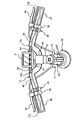
図2を参照して、自転車用ヘッドセット構造11は、基本的に、ステムボルトすなわちステアリング部材固定部材50と、ハンドルバー取付部材51と、トップ側管状スペーサ部材52と、トップ側ステアリングベアリングセット53と、ボトム側ステアリングベアリングセット54と、ボトム側管状スペーサ部材55とを備える。また、自転車用ヘッドセット構造11は、好ましくは、一端がメイン電気コード41に電気的に接続されるとともにフロント及びリア装置すなわち部品との連結のために他端で2つの部分に分かれる内装ヘッドセットワイヤリングケーブルすなわちコード56を備える。
Referring to FIG. 2, the
本発明において、自転車用ヘッドセット構造11は、フロントフォーク18のステアリングチューブ18aに装着されており、これにより、ステアリングチューブ18aはヘッドチューブ12d内で回転自在である。このように、図2に示す通り、ハンドルバー17は、ハンドルバー取付部材51によって、フロントフォーク18のステアリングチューブ18aに、従来と同様に、固定される。つまり、メインフレーム12に対して相対的にフロントフォーク18及びフロントホイール14を回転させるよう、ハンドルバー17はフロントフォーク18に固定される。
In the present invention, the
詳細には、トップ側管状スペーサ部材52は、回転運動のためトップ側ベアリングセット53を介してヘッドチューブ12dの上端部にステアリングチューブ18aの上端部を支持する。また、ボトム側管状スペーサ部材55は、回転運動のためボトム側ベアリングセット54を介してヘッドチューブ12dの下端部にステアリングチューブ18aの下端部を支持する。このように、トップ側及びボトム側ベアリングセット53,54は、トップ側及びボトム側管状スペーサ部材52,55と、ヘッドチューブ12dの上端部及び下端部とのそれぞれの間に配置される。
Specifically, the top
このように、自転車用ヘッドセット構造11を組み立てる際に、トップ側及びボトム側ベアリングセット53,54は、トップ側及びボトム側管状スペーサ部材52,55とともに、ヘッドチューブ12dの上端部及び下端部に配置される。そして、ステアリングチューブ18aはヘッドチューブ12dに挿入されて、ステアリングチューブ18aがトップ側及びボトム側管状スペーサ部材52,55によってヘッドチューブ12dに回転可能に支持される。次に、ハンドルバー取付部材51が、ステアリングチューブ18aの上部自由端へ挿入される。ハンドルバー取付部材51がステアリングチューブ18aに固定して留められる前に(つまり、緩めに取付けられて)、ステムボルト50がステアリングチューブ18aの内部に挿入され、ステアリングチューブ18aを上方へ引っ張りハンドルバー取付け部材51を下向きに押す軸方向の力を印加するよう調整され、これにより、軸方向にトップ側及びボトム側ベアリングセット53,54に荷重がかけられる。このように、自転車用ヘッドセット構造11は、ハンドルバー取付部材51に下向きの圧力を作用させるよう構成され、それによりトップ側及びボトム側ベアリングセット53,54の下向きの圧力すなわち軸方向の力を作用させる。自転車用ヘッドセット構造11のこの軸方向の力が、トップ側及びボトム側ベアリングセット53,54に、ユーザが適切な負荷を印加することを可能にする。
As described above, when the
図2に示す通り、ハンドルバー取付部材51は、自転車用ハンドルバー17を固定するよう構成されるハンドルバー装着部60と、中間伸張部61と、自転車用ステアリングチューブ18aを固定するよう構成されるステアリングチューブ取付部62とを備える。ハンドルバー装着部60は、留め具64、例えばボルト及びナットによって締め付けられるチューブクランプとして構成される。同様に、ステアリングチューブ取付部62は、1組の留め具65、たとえば1組のボルト及び1組のナットによって締め付けられるチューブクランプとして構成される。このように、ステアリングチューブ取付部62は、自転車用ステアリングチューブ18aを収容するよう必要な大きさにされる径方向に締め付け可能な内径の内周部66を有する。径方向に締め付け可能な内径の内周部66は、ハンドルバー取付部材51のワイヤリング通路の一部を形成するノッチ67を有する。
As shown in FIG. 2, the
中間伸張部61は、好ましくは、ハンドルバー取付部材51のワイヤリング通路68を形成するよう、少なくとも部分的に中空である。ワイヤリング通路68は、ステアリングチューブ取付部62のノッチ67に開口する第1ワイヤリング開口部69と、中間伸張部61の底部に開口する第2ワイヤリング開口部70とを有する。このように、メイン電気コード41は、第2ワイヤリング開口部70を介して内装ヘッドセットワイヤリングコード56に電気的に接続される。もちろん、必要に応じて、及び/または所望により、メイン電気コード41及び内装ヘッドセットワイヤリングコード56は、単一の集合コードとすることもできる。
The
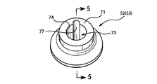
図2からわかる通り、トップ側及びボトム側管状スペーサ部材52,55は、それぞれ、硬い剛性材料から、好ましくは、一体の単一部材として構成される。より好ましくは、トップ側及びボトム側管状スペーサ部材52,55は、自転車に適した金属材料で構成される。トップ側及びボトム側管状スペーサ部材52,55は互いに同一であるが、ボトム側管状スペーサ部材55はトップ側管状スペーサ部材52に対して反転されたものである。したがって、トップ側管状スペーサ部材52のみを、詳細に説明、例示する。
As can be seen from FIG. 2, the top and bottom
図4〜図6に示す通り、トップ側管状スペーサ部材52は、第1端部71と、第2端部72とを有しており、中央軸方向通路73が第1及び第2端部71,72の間に延びている。このように、第1端部71は第1すなわち上端開口部74を有し、第2端部72は第2すなわち下端開口部75を有している。中央軸方向通路73は、自転車用ステアリングチューブ18aを収容するよう必要な大きさにされる。好ましくは、中央軸方向通路73は略円筒状の内面を有する。
As shown in FIGS. 4 to 6, the top
トップ側管状スペーサ部材52の外面は、好ましくは、トップ側ステアリングベアリングセット53を支持する階段状である。詳細には、トップ側管状スペーサ部材52の第1(上部)端部71は、第1最大幅を有する第1環状部を有し、また、トップ側管状スペーサ部材52の第2(下部)端部72は、第1最大幅より小さい第2最大幅を有する第2環状部を有しており、これにより、軸方向に面する当接部76がそれら間に形成される。トップ側ステアリングベアリングセット53は、トップ側管状スペーサ部材52の第2(下部)端部72上で支持され、軸方向に面する当接部76と当接する。
The outer surface of the top
ワイヤリング経路77は、管状スペーサ部材52の第1及び第2端部の間に縦方向に延びる。好ましくは、ワイヤリング経路77は、中央軸方向通路73の略円筒状の内面に形成される、軸方向に延びるノッチである。ワイヤリング経路77は、ハンドルバー取付部材51及び管状スペーサ部材52が自転車用ステアリングチューブ18aに取り付けられるとき、ハンドルバー取付部材51のノッチ67及びワイヤリング通路68と連通するよう配置される。したがって、内装ヘッドセットワイヤリングコード56はハンドルバー取付部材51からヘッドチューブ12dへ通ることができ、これにより、内装ヘッドセットワイヤリングコード56がステアリングチューブ18aと共に移動することになる。
The
図2を再び参照して、ステムボルトすなわちステアリング部材固定部材50は、自転車用ステアリングチューブ18aの内部孔と係合するよう必要な大きさにされる拡張可能なナット50aと、拡張可能なナット50aに螺合されるボルト50bとを有する従来同様の構造である。ヘッド部50cを備えるボルト50bは、ハンドルバー取付部材51のステアリングチューブ取付部62と係合するよう必要な大きさにされる。
Referring again to FIG. 2, the stem bolt or steering
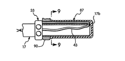
次に図3及び図7〜図11を参照して、サイクルコンピュータ31からハンドルバー17に装着される電子シフタ32,33までのワイヤリングを説明する。好ましくは、ハンドルバー17は、シフトコード42,43をそれぞれ保護するよう、1組の保護チューブ82,84を有する。シフトコード42,43を保護するよう、保護チューブ82,84が、サイクルコンピュータ31からハンドルバー17の開口部17aにそれぞれ延設される。
Next, the wiring from the
好ましい実施形態において、シフトコード42,43は、ハンドルバー端部の中空の内部を通って延び、そして、ハンドルバー17の外部の電子シフタ32,33に戻ってそれらに接続されるように、ハンドルバー17の自由端を回って巻き付けられる。好ましい実施形態において、ハンドルバー17は、シフトコード42,43を所定の位置に保持するよう、左右のハンドルバーグリップ87を備える。基本的に、ハンドグリップ87は同一である。したがって、ここでは、一方のハンドグリップ87のみを、詳細に説明、及び例示する。
In the preferred embodiment, the
好ましくは、ハンドルバー17の自由端は、ワイヤ42,43を収容するノッチ17bを有する。つまり、シフトコード42,43が、ハンドルバー17の自由端を回って巻き付けられるとき、シフトコード42,43はノッチ17b内に配置される。したがって、グリップ87がハンドルバー17の端部に挿入されるとき、シフトコード42,43がグリップ87によって歪んだりしない。また、グリップ87は、好ましくは、縦方向に延設される溝87aをそれぞれ備えており、これにより、グリップ87がハンドルバー17の自由端に取り付けられるとき、シフトコード42,43を縦方向の溝87a内に配置することができる。好ましくは、ブレーキレバー92のブレーキ装着部90は、グリップ87と同様のタイプの断面を有しており、これにより、シフトコード42,43がブレーキレバー92の装着部90とハンドルバー17の外面との間を通ることができる。
Preferably, the free end of the
フロントシフトユニット32は、サイクルコンピュータ31がライダーによってマニュアルモードにセットされたときに、フロントディレーラ25を手動でシフトさせる1組のシフトプッシュボタンを備える。図3に示す通り、フロントシフトユニット32は、電気コード42によってサイクルコンピュータ31に電気的に接続される。この実施形態において、フロントシフトユニット32がサイクルコンピュータ31へ電気的なコマンドを入力する。
The
リアシフトユニット33は、サイクルコンピュータ31がライダーによってマニュアルモードにプログラムされ、あるいはセットされたときに、リアディレーラ29を手動でシフトさせる1組のシフトプッシュボタンを備える。この実施形態において、リアシフトユニット33は、電気コード43によってサイクルコンピュータ31に電気的に接続される。好ましい実施例において、リアシフトユニット33がサイクルコンピュータ31へ電気的なコマンドを入力する。
The
ここでは、「ほぼ」、「およそ」、「約」といった程度を示す用語は、最終結果が大きく変わらないような、妥当な変形の条件の変更量を意味するものとして用いる。変更が、変形という語の意味を損なわない限り、これらの用語には変形の条件の少なくとも±5%の変更を含むものとする。 Here, terms indicating degrees such as “almost”, “approximately”, and “about” are used to mean a change amount of an appropriate deformation condition that does not greatly change the final result. Unless the change impairs the meaning of the word deformation, these terms shall include a change of at least ± 5% of the deformation conditions.
本発明の説明のためにいくつかの実施形態が選択されただけであって、添付の特許請求の範囲に記載された本発明の範囲を逸脱することがない範囲で、種々の変更、変形ができることは、本開示から当業者には明らかであろう。さらに、前述の本発明にかかる実施形態の説明は単なる例示であって、添付の特許請求の範囲及びそれらの均等物によって決められる本発明を限定するものではないことは、本開示から当業者には明らかであろう。 Only a few embodiments have been selected for the description of the present invention, and various changes and modifications may be made without departing from the scope of the present invention as set forth in the appended claims. It will be apparent to those skilled in the art from this disclosure. Furthermore, it should be understood by those skilled in the art from this disclosure that the foregoing descriptions of the embodiments of the present invention are merely illustrative and are not intended to limit the present invention as defined by the appended claims and their equivalents. Will be clear.
10 自転車
11 自転車用ヘッドセット構造
17 ハンドルバー
18a ステアリングチューブ
52 トップ側管状スペーサ部材
55 ボトム側管状スペーサ部材
60 ハンドルバー装着部
62 ステアリングチューブ取付部
67 ノッチ
68 ワイヤリング通路
69 第1ワイヤリング開口部
70 第2ワイヤリング開口部
71 第1端部
72 第2端部
73 中央軸方向通路
74 上端開口部
75 下端開口部
76 当接部
77 ワイヤリング経路
DESCRIPTION OF
Claims (9)
上端開口部を有する第1端部と、下端開口部を有する第2端部と、前記第1端部と前記第2端部との間に延びるワイヤリング経路と、前記上端開口部と前記下端開口部との間で軸方向に伸びる軸方向通路とを有し、前記軸方向通路は前記自転車用ステアリングチューブを収容可能な管状スペーサ部材とを備え、
前記ワイヤリング経路は、前記ハンドルバー取付部材及び前記管状スペーサ部材が前記自転車用ステアリングチューブに取り付けられたとき、前記ハンドルバー取付部材のワイヤリング通路と連通し、
前記管状スペーサ部材は、第1最大幅を有する第1環状部と、前記第1最大幅より小さい第2最大幅を有する第2環状部とを有しており、軸方向に面する当接部が前記第1環状部と第2環状部との間に形成されている、
自転車用ヘッドセット構造。 A handlebar mounting portion configured to fix the bicycle handlebar; and a steering tube mounting portion configured to fix the bicycle steering tube; and the handlebar mounting portion and the steering tube mounting portion. A handlebar mounting member having a wiring passage extending therebetween;
A first end having an upper end opening; a second end having a lower end opening; a wiring path extending between the first end and the second end; the upper end opening and the lower end opening An axial passage extending in the axial direction with the portion, the axial passage comprising a tubular spacer member capable of accommodating the bicycle steering tube,
The wiring path, when said handlebar mounting member and the tubular spacer member is attached to the bicycle steerer tube, and wiring passage and communicating the handlebar mounting member,
The tubular spacer member has a first annular portion having a first maximum width and a second annular portion having a second maximum width smaller than the first maximum width, and a contact portion facing in the axial direction. Is formed between the first annular portion and the second annular portion,
Bicycle headset structure.
前記ボルトは前記ハンドルバー取付部材の前記ステアリングチューブ取付部と係合可能なヘッド部を有する、
請求項1に記載の自転車用ヘッドセット構造。 A steering tube fixing member further comprising a nut that is expandable so as to be engageable with an inner periphery of the bicycle steering tube; and a bolt that is screwed into the nut.
The bolt has a head portion engageable with the steering tube mounting portion of the handlebar mounting member.
The bicycle headset structure according to claim 1.
前記ワイヤリング経路が、前記軸方向通路の略円筒状の内面に形成されて軸方向に延びるノッチである、
請求項1に記載の自転車用ヘッドセット構造。 The axial passage has a substantially cylindrical inner surface;
The wiring path is a notch formed in a substantially cylindrical inner surface of the axial path and extending in the axial direction;
The bicycle headset structure according to claim 1.
上端開口部を有する第1端部と、
下端開口部を有する第2端部と、
前記上端開口部と前記下端開口部との間に軸方向に延び、自転車用ステアリングチューブを収容可能な中央通路と、
前記上端開口部及び前記下端開口部の一方から前記上端開口部及び前記下端開口部の他方へ向かって延びて設けられたワイヤリング経路とを備え、
前記ワイヤリング経路は、この管状スペーサ部材が前記自転車用ステアリングチューブに取り付けられるとき、前記自転車用ステアリングチューブの外周面の外側に空間を形成するように構成されており、
前記第2端部は、第1最大幅を有する第1環状部と、前記第1最大幅より小さい第2最大幅を有する第2環状部とを有しており、軸方向に面する当接部が前記第1環状部と前記第2環状部との間に形成されている、
管状スペーサ部材。 A tubular spacer member used in a bicycle headset structure disposed under a handlebar mounting member,
A first end having an upper end opening;
A second end having a lower end opening;
A central passage that extends in the axial direction between the upper end opening and the lower end opening and can accommodate a bicycle steering tube;
A wiring path provided extending from one of the upper end opening and the lower end opening toward the other of the upper end opening and the lower end opening;
The wiring path is configured to form a space outside the outer peripheral surface of the bicycle steering tube when the tubular spacer member is attached to the bicycle steering tube .
The second end portion includes a first annular portion having a first maximum width and a second annular portion having a second maximum width smaller than the first maximum width, and abutting in the axial direction. A portion is formed between the first annular portion and the second annular portion,
Tubular spacer member.
前記ワイヤリング経路は前記中央通路の略円筒状の内面に形成され軸方向に延設しているノッチである、請求項8に記載の管状スペーサ部材。 The central passage has a substantially cylindrical inner surface;
The tubular spacer member according to claim 8 , wherein the wiring path is a notch formed on a substantially cylindrical inner surface of the central path and extending in the axial direction.
Applications Claiming Priority (1)
| Application Number | Priority Date | Filing Date | Title |
|---|---|---|---|
| US10/848,569 US6983949B2 (en) | 2004-05-19 | 2004-05-19 | Bicycle headset structure |
Publications (2)
| Publication Number | Publication Date |
|---|---|
| JP2005329938A JP2005329938A (en) | 2005-12-02 |
| JP4164080B2 true JP4164080B2 (en) | 2008-10-08 |
Family
ID=34927888
Family Applications (1)
| Application Number | Title | Priority Date | Filing Date |
|---|---|---|---|
| JP2005136891A Active JP4164080B2 (en) | 2004-05-19 | 2005-05-10 | Bicycle headset structure |
Country Status (6)
| Country | Link |
|---|---|
| US (1) | US6983949B2 (en) |
| EP (2) | EP1598263B1 (en) |
| JP (1) | JP4164080B2 (en) |
| CN (1) | CN1699109B (en) |
| DE (1) | DE602004029141D1 (en) |
| TW (1) | TWI243131B (en) |
Families Citing this family (61)
| Publication number | Priority date | Publication date | Assignee | Title |
|---|---|---|---|---|
| US7891687B2 (en) * | 2004-12-10 | 2011-02-22 | Magna Marque International Inc. | Method to conceal bicycle control cables within the handlebars, stem and frame |
| JP4286229B2 (en) * | 2005-01-20 | 2009-06-24 | 株式会社シマノ | Bicycle handlebar |
| JP2006244743A (en) * | 2005-03-01 | 2006-09-14 | Shimano Inc | Wiring connection structure for bicycle |
| TWM280973U (en) * | 2005-04-14 | 2005-11-21 | Tsang-Bing Chen | Bicycle frame with concealed gearshift cable |
| US7357403B2 (en) * | 2005-05-26 | 2008-04-15 | Vincenzo F Costa | Fork tree upper clamp |
| JP4164087B2 (en) * | 2005-11-16 | 2008-10-08 | 株式会社シマノ | Bicycle cable routing device |
| JP2007276549A (en) * | 2006-04-03 | 2007-10-25 | Yamaha Motor Co Ltd | Motorcycle |
| CN201086794Y (en) * | 2007-06-05 | 2008-07-16 | 深圳信隆实业股份有限公司 | Mounting structure of bicycle control cable |
| ITMI20071352A1 (en) * | 2007-07-06 | 2009-01-07 | Campagnolo Srl | INSTRUMENTATION KIT OF A BICYCLE AND BICYCLE INCLUDING SUCH A KIT |
| US20110121538A1 (en) * | 2008-06-06 | 2011-05-26 | Michel Giroux | Fork assembly for a bicycle |
| WO2009146551A1 (en) * | 2008-06-06 | 2009-12-10 | Société de vélo en libre-service | Handlebar for a bicycle |
| US7854442B2 (en) * | 2008-08-29 | 2010-12-21 | Shimano Inc. | Bicycle wire holding arrangement |
| TW201114645A (en) * | 2009-10-20 | 2011-05-01 | shi-jie Zhang | Standpipe upper cover and manufacturing method thereof |
| NL2003770C2 (en) * | 2009-11-09 | 2011-05-11 | Batavus Bv | COUPLER AND METHOD FOR MANUFACTURING A BIKE FRAME. |
| TWI623463B (en) * | 2010-07-09 | 2018-05-11 | 沙維設計控股公司 | Improvements in or relating to cycle headsets |
| WO2012020303A2 (en) * | 2010-08-12 | 2012-02-16 | Douglas Gregg Shadwell | Apparatus and method for routing bicycle control cables |
| ITVI20110152A1 (en) * | 2011-06-09 | 2012-12-10 | Wilier Triestina S P A | FORK FOR BICYCLES AND BICYCLE INCLUDING THIS FORK |
| CA2781239A1 (en) * | 2011-07-04 | 2013-01-04 | Pon Bicycle Holding B.V. | Head tube assembly for a bicycle with cable access routing in an open steerer configuration |
| GB2494714A (en) * | 2011-09-19 | 2013-03-20 | Karbon Kinetics Ltd | Internal cable routing at headset |
| US8408349B1 (en) | 2011-09-22 | 2013-04-02 | Faraday Bicycles, Inc. | Electric bicycle |
| US9403572B2 (en) * | 2013-07-01 | 2016-08-02 | Specialized Bicycle Components, Inc. | Bicycle frame with internal cable routing and method for making the same |
| EP3038891A4 (en) * | 2013-09-16 | 2017-05-10 | Recreation Systems Inc. | Handle assembly and associated components for a cycle |
| US9615472B1 (en) | 2013-09-16 | 2017-04-04 | Craig Calfee | Preload anchoring mechanism with top cap adapted to receive subsystems, controls, indicators, and the like |
| US9010789B1 (en) * | 2014-01-10 | 2015-04-21 | Neco Technology Industry Co., Ltd. | Head parts assembly for a bicycle |
| US9242692B2 (en) | 2014-03-17 | 2016-01-26 | Shimano Inc. | Compression ring and head parts |
| US9446812B2 (en) | 2014-03-17 | 2016-09-20 | Shimano Inc. | Bicycle stem |
| EP2923935A1 (en) * | 2014-03-28 | 2015-09-30 | Neco Technology Industry Co., Ltd. | Head tube and control cable assembly for a bicycle |
| US9457859B2 (en) | 2014-04-17 | 2016-10-04 | Shimano Europe B.V. | Bicycle top cap |
| CN103963897A (en) * | 2014-05-06 | 2014-08-06 | 王民海 | Connection method of front fork and vehicle body |
| WO2015180756A1 (en) * | 2014-05-27 | 2015-12-03 | Bmc Switzerland Ag | Bicycle fork, bicycle frame and bicycle |
| US9701293B2 (en) | 2014-06-19 | 2017-07-11 | Specialized Bicycle Components, Inc. | Bicycle cable routing system |
| US9056646B1 (en) | 2014-06-19 | 2015-06-16 | Specialized Bicycle Components, Inc. | Bicycle cable routing system |
| US9174695B1 (en) * | 2014-07-10 | 2015-11-03 | Neco Technology Industry Co., Ltd. | Head parts assembly for a bicycle with a cable collecting device |
| EP2965981B1 (en) * | 2014-07-11 | 2017-01-25 | Neco Technology Industry Co., Ltd. | Bicycle |
| DE102014111917A1 (en) * | 2014-08-20 | 2016-02-25 | Gustav Magenwirth Gmbh & Co. Kg | Hand-operated transmitter unit |
| US9580130B2 (en) * | 2015-02-26 | 2017-02-28 | Ford Global Technologies, Llc | Bicycle with detachable head-tube subassembly |
| US10689056B2 (en) * | 2015-04-14 | 2020-06-23 | Matthew Hendey | Apparatus, systems, and methods for preventing migration of contaminants within tubing of a frame |
| US10150530B2 (en) * | 2015-05-21 | 2018-12-11 | Trek Bicycle Corporation | Rigid frame with high-compliance seat tube and internal cable routing |
| DE202015004668U1 (en) * | 2015-07-02 | 2016-10-05 | Canyon Bicycles Gmbh | Bicycle handle as well as bicycle handlebar handlebar system |
| TWI568622B (en) * | 2015-11-13 | 2017-02-01 | 溫芫鋐 | Cable arranging system for bicycle |
| CN106364615A (en) * | 2016-09-30 | 2017-02-01 | 北京野兽科技有限公司 | Inner line running bicycle frame and line running method for bicycle frame |
| US10858061B2 (en) * | 2017-05-18 | 2020-12-08 | Carla Marie Montez | Integrated handlebar system and method |
| US10812645B2 (en) * | 2017-05-18 | 2020-10-20 | Carla Marie Montez | Handlebar systems and method |
| CH714098A2 (en) * | 2017-08-29 | 2019-03-15 | Mystromer Ag | Hollow-cylindrical component and stem for a bicycle and bicycle. |
| AT520501B1 (en) | 2017-10-06 | 2019-09-15 | Airstreeem Com Gmbh | Arrangement of a frame for a bicycle and a bicycle handlebar |
| TWI672241B (en) * | 2018-03-07 | 2019-09-21 | 天心工業股份有限公司 | Bicycle head and its standpipe |
| CN108482556B (en) * | 2018-04-10 | 2020-02-18 | 常州洪记两轮智能交通工具有限公司 | Wiring system in bicycle |
| US10953948B2 (en) * | 2018-05-31 | 2021-03-23 | Tien Hsin Industries Co., Ltd. | Cable routing system of bicycle and stem thereof |
| DE102018006153B4 (en) * | 2018-08-03 | 2021-05-06 | Hans-Jürgen Schlender | Headset for the rotatable mounting of a steerer tube |
| DE102019002207B4 (en) * | 2019-03-27 | 2020-11-26 | Hans-Jürgen Schlender | Cable guide for releasably receiving and fixing at least one cable on a handlebar of a two-wheeler |
| DE202019104749U1 (en) * | 2019-08-29 | 2019-09-11 | Scott Sports Sa | Handlebar stem with integrated cable guide |
| NL2023744B1 (en) * | 2019-09-02 | 2021-05-12 | Koninklijke Gazelle N V | Bicycle |
| NL2024186B1 (en) * | 2019-11-07 | 2021-09-29 | Vanmoof Bv | CYCLE HANDLEBAR |
| WO2021209937A1 (en) * | 2020-04-17 | 2021-10-21 | Calamus Electric Private Limited | A handlebar assembly for a bicycle |
| DE102020116139A1 (en) | 2020-06-18 | 2021-12-23 | Bayerische Motoren Werke Aktiengesellschaft | Front wheel guidance for a tilting vehicle as well as a tilting vehicle |
| US11794848B2 (en) | 2020-12-14 | 2023-10-24 | Sram, Llc | Hydraulic brake control device with handlebar proximal hose attachment |
| US11912372B2 (en) | 2020-12-14 | 2024-02-27 | Sram, Llc | Hydraulic brake control device with handlebar proximal hose attachment |
| TWM621827U (en) | 2021-08-27 | 2022-01-01 | 信隆車料工業股份有限公司 | Wire positioning apparatus for bicycle |
| AT525529A1 (en) * | 2021-09-30 | 2023-04-15 | Simplon Fahrrad Gmbh | Bicycle with a bicycle frame and a front fork |
| DE202022100922U1 (en) | 2022-02-17 | 2022-02-23 | Scott Sports Sa | Arrangement for connecting a bicycle handlebar to a bicycle fork |
| CN115320757A (en) * | 2022-07-15 | 2022-11-11 | 拓肯兴业股份有限公司 | Wiring device for vehicle wire |
Family Cites Families (41)
| Publication number | Priority date | Publication date | Assignee | Title |
|---|---|---|---|---|
| GB274643A (en) * | 1926-07-22 | 1927-07-28 | A M A C Ltd | Improvements in twisting handlebar controls for motor cycles and the like |
| JPS5655108Y2 (en) | 1977-07-12 | 1981-12-22 | ||
| JPS5831748Y2 (en) | 1978-07-12 | 1983-07-14 | 株式会社シマノ | Fixed structure of bicycle handle stem |
| US4435983A (en) | 1980-11-22 | 1984-03-13 | Shimano Industrial Company Limited | Handle stem for a bicycle |
| US4489307A (en) | 1981-05-23 | 1984-12-18 | Shimano Industrial Company Limited | Handle stem for a bicycle |
| JPS6240868U (en) | 1985-08-30 | 1987-03-11 | ||
| US4653768A (en) * | 1986-03-26 | 1987-03-31 | Keys Kenney L | Free spinning handlebar-brake cable connection |
| US4770435A (en) * | 1987-06-29 | 1988-09-13 | North America Tradimpex Cycles, Inc. | Freestyle bicycle construction |
| US4966047A (en) * | 1987-12-07 | 1990-10-30 | Alwin Krauer | Handlebar-mounted cable control |
| US4881750A (en) | 1989-02-06 | 1989-11-21 | Hartmann Dirck T | ATB shock absorber |
| WO1990013470A1 (en) * | 1989-05-03 | 1990-11-15 | Ueli Eser | Hydraulic rim brake on a bicycle |
| DE3934960A1 (en) | 1989-10-20 | 1991-04-25 | Stabilus Gmbh | RELEASE DEVICE FOR PNEUMATIC AND HYDROPNEUMATIC HEIGHT ADJUSTMENT DEVICES |
| US5095770B1 (en) | 1990-09-28 | 2000-01-25 | Homer J Radar | Steering bearing assembly for wheeled vehicle |
| JP2546159Y2 (en) | 1991-11-05 | 1997-08-27 | 株式会社シマノ | Bicycle head parts |
| US5248159A (en) | 1992-02-18 | 1993-09-28 | Moore James D | Lightweight self-adjusting semihydraulic suspension system |
| US5305654A (en) | 1993-06-07 | 1994-04-26 | Durham Roger O | Headset for bicycles with external forks |
| US5319993A (en) | 1993-09-02 | 1994-06-14 | Tien Hsin Industries Co., Ltd. | Steering bearing assembly for a bicycle |
| US5496126A (en) | 1994-12-20 | 1996-03-05 | Lin; Wen-Hwa | Bicycle front fork mounting structure |
| US6167780B1 (en) | 1995-01-24 | 2001-01-02 | Sheng-Luen Chen | Device for making micro adjusting the steering bearing of bicycle |
| JPH08290793A (en) | 1995-02-21 | 1996-11-05 | Marui:Kk | Ball bearing for bicycle head set and structure of its attaching part |
| US6145637A (en) | 1995-02-23 | 2000-11-14 | Hopey; Timothy C. | Steering damper in and for vehicles |
| US5647684A (en) | 1995-05-16 | 1997-07-15 | Chen; Chia-Ching | Two-step and toothless bicycle head shaft bowl set |
| US5826898A (en) | 1995-12-04 | 1998-10-27 | Fortier; Robert L. | Modular steering headset for use on a bicycle |
| US5927740A (en) | 1996-08-14 | 1999-07-27 | Hopey; Timothy C. | Steering damper in and for vehicles |
| US5800071A (en) | 1996-12-05 | 1998-09-01 | Chi; Yi-Chen | Journal for a head tube of a bicycle |
| US6050583A (en) | 1997-01-13 | 2000-04-18 | Bohn; David D. | Electronically controlled bicycle suspension apparatus |
| US5971116A (en) | 1997-03-13 | 1999-10-26 | Cannondale Corporation | Electronic suspension system for a wheeled vehicle |
| US6122991A (en) * | 1998-02-10 | 2000-09-26 | Clarkson; Douglas Dean | Handlebar assembly for vehicles and method for making the same |
| US5918895A (en) | 1998-05-28 | 1999-07-06 | Chi; Yi-Chen | Headset assembly for a bicycle |
| US6019017A (en) | 1999-03-15 | 2000-02-01 | Lin; King-Chen | Upper headset assembly for a bicycle |
| US6220398B1 (en) * | 1999-11-01 | 2001-04-24 | Wu Chin-Chang | Brake cable positioning assembly for an inner swivel connector of a free style bicycle |
| US6543799B2 (en) | 2000-01-13 | 2003-04-08 | Shimano Inc. | Bicycle suspension |
| US6310260B1 (en) * | 2000-03-15 | 2001-10-30 | Union Carbide Chemicals & Plastics Technology Corporation | Separation processes |
| IT1320338B1 (en) * | 2000-05-09 | 2003-11-26 | Campagnolo Srl | STEERING GROUP FOR A BICYCLE. |
| JP3476746B2 (en) | 2000-05-29 | 2003-12-10 | 株式会社マルイ | Bicycle haw stem support structure |
| US6584872B1 (en) * | 2000-10-31 | 2003-07-01 | Shimano Inc. | Bicycle handle mounting member |
| US6343806B1 (en) | 2001-03-29 | 2002-02-05 | Qun-Yuan Lee | Bicycle head set assembly |
| US6711966B2 (en) | 2002-01-25 | 2004-03-30 | Louis Chuang | Accessory-mounting device for a bicycle |
| JP3635306B2 (en) * | 2002-06-11 | 2005-04-06 | 株式会社キャットアイ | Handle stem and speed indicator |
| DE102004014467A1 (en) * | 2003-03-26 | 2004-11-18 | Schmider, John, Thornhill | Control cabling system for bicycle e.g. mountain bike, has control cables passing through bent stem gooseneck and passing out at bottom of gooseneck such that gooseneck acts as cable conduit |
| US7080848B2 (en) * | 2003-09-17 | 2006-07-25 | Shimano Inc. | Bicycle head cap unit |
-
2004
- 2004-05-19 US US10/848,569 patent/US6983949B2/en active Active
- 2004-11-10 TW TW093134330A patent/TWI243131B/en not_active IP Right Cessation
- 2004-12-21 EP EP04030301A patent/EP1598263B1/en active Active
- 2004-12-21 EP EP10176640A patent/EP2258613B1/en active Active
- 2004-12-21 DE DE602004029141T patent/DE602004029141D1/en active Active
- 2004-12-30 CN CN2004101037090A patent/CN1699109B/en active Active
-
2005
- 2005-05-10 JP JP2005136891A patent/JP4164080B2/en active Active
Also Published As
| Publication number | Publication date |
|---|---|
| US20050258617A1 (en) | 2005-11-24 |
| EP2258613A2 (en) | 2010-12-08 |
| EP1598263B1 (en) | 2010-09-15 |
| TW200538345A (en) | 2005-12-01 |
| CN1699109A (en) | 2005-11-23 |
| US6983949B2 (en) | 2006-01-10 |
| EP2258613B1 (en) | 2012-07-04 |
| DE602004029141D1 (en) | 2010-10-28 |
| TWI243131B (en) | 2005-11-11 |
| CN1699109B (en) | 2011-08-03 |
| EP1598263A2 (en) | 2005-11-23 |
| JP2005329938A (en) | 2005-12-02 |
| EP1598263A3 (en) | 2006-10-04 |
| EP2258613A3 (en) | 2011-01-19 |
Similar Documents
| Publication | Publication Date | Title |
|---|---|---|
| JP4164080B2 (en) | Bicycle headset structure | |
| US7093844B2 (en) | Bicycle headset structure | |
| JP4164087B2 (en) | Bicycle cable routing device | |
| US7080848B2 (en) | Bicycle head cap unit | |
| US7922612B2 (en) | Power supply structure for bicycles | |
| EP1529725B1 (en) | Expandable bicycle headset structure | |
| US7438159B2 (en) | Bicycle motion sensing arrangement | |
| JP2021183442A (en) | Bicycle battery holder, bicycle battery and bicycle having the same | |
| TW202321099A (en) | Electrical device for headset assembly of human-powered vehicle | |
| JPH01132487A (en) | Handle for bicycle |
Legal Events
| Date | Code | Title | Description |
|---|---|---|---|
| A977 | Report on retrieval |
Free format text: JAPANESE INTERMEDIATE CODE: A971007 Effective date: 20080325 |
|
| A131 | Notification of reasons for refusal |
Free format text: JAPANESE INTERMEDIATE CODE: A131 Effective date: 20080401 |
|
| RD02 | Notification of acceptance of power of attorney |
Free format text: JAPANESE INTERMEDIATE CODE: A7422 Effective date: 20080502 |
|
| A521 | Request for written amendment filed |
Free format text: JAPANESE INTERMEDIATE CODE: A523 Effective date: 20080522 |
|
| TRDD | Decision of grant or rejection written | ||
| A01 | Written decision to grant a patent or to grant a registration (utility model) |
Free format text: JAPANESE INTERMEDIATE CODE: A01 Effective date: 20080701 |
|
| A01 | Written decision to grant a patent or to grant a registration (utility model) |
Free format text: JAPANESE INTERMEDIATE CODE: A01 |
|
| A61 | First payment of annual fees (during grant procedure) |
Free format text: JAPANESE INTERMEDIATE CODE: A61 Effective date: 20080725 |
|
| FPAY | Renewal fee payment (event date is renewal date of database) |
Free format text: PAYMENT UNTIL: 20110801 Year of fee payment: 3 |
|
| R150 | Certificate of patent or registration of utility model |
Free format text: JAPANESE INTERMEDIATE CODE: R150 Ref document number: 4164080 Country of ref document: JP Free format text: JAPANESE INTERMEDIATE CODE: R150 |
|
| FPAY | Renewal fee payment (event date is renewal date of database) |
Free format text: PAYMENT UNTIL: 20110801 Year of fee payment: 3 |
|
| FPAY | Renewal fee payment (event date is renewal date of database) |
Free format text: PAYMENT UNTIL: 20120801 Year of fee payment: 4 |
|
| R250 | Receipt of annual fees |
Free format text: JAPANESE INTERMEDIATE CODE: R250 |
|
| FPAY | Renewal fee payment (event date is renewal date of database) |
Free format text: PAYMENT UNTIL: 20120801 Year of fee payment: 4 |
|
| FPAY | Renewal fee payment (event date is renewal date of database) |
Free format text: PAYMENT UNTIL: 20130801 Year of fee payment: 5 |
|
| R250 | Receipt of annual fees |
Free format text: JAPANESE INTERMEDIATE CODE: R250 |
|
| R250 | Receipt of annual fees |
Free format text: JAPANESE INTERMEDIATE CODE: R250 |
|
| R250 | Receipt of annual fees |
Free format text: JAPANESE INTERMEDIATE CODE: R250 |
|
| R250 | Receipt of annual fees |
Free format text: JAPANESE INTERMEDIATE CODE: R250 |
|
| R250 | Receipt of annual fees |
Free format text: JAPANESE INTERMEDIATE CODE: R250 |
|
| R250 | Receipt of annual fees |
Free format text: JAPANESE INTERMEDIATE CODE: R250 |
|
| R250 | Receipt of annual fees |
Free format text: JAPANESE INTERMEDIATE CODE: R250 |
|
| R250 | Receipt of annual fees |
Free format text: JAPANESE INTERMEDIATE CODE: R250 |
|
| R250 | Receipt of annual fees |
Free format text: JAPANESE INTERMEDIATE CODE: R250 |
|
| R250 | Receipt of annual fees |
Free format text: JAPANESE INTERMEDIATE CODE: R250 |
|
| R250 | Receipt of annual fees |
Free format text: JAPANESE INTERMEDIATE CODE: R250 |
|
| R250 | Receipt of annual fees |
Free format text: JAPANESE INTERMEDIATE CODE: R250 |