JP4163458B2 - Method for manufacturing electrical contacts - Google Patents
Method for manufacturing electrical contacts Download PDFInfo
- Publication number
- JP4163458B2 JP4163458B2 JP2002203964A JP2002203964A JP4163458B2 JP 4163458 B2 JP4163458 B2 JP 4163458B2 JP 2002203964 A JP2002203964 A JP 2002203964A JP 2002203964 A JP2002203964 A JP 2002203964A JP 4163458 B2 JP4163458 B2 JP 4163458B2
- Authority
- JP
- Japan
- Prior art keywords
- substrate
- micro
- manufacturing
- electrical contact
- present
- Prior art date
- Legal status (The legal status is an assumption and is not a legal conclusion. Google has not performed a legal analysis and makes no representation as to the accuracy of the status listed.)
- Expired - Fee Related
Links
- 238000000034 method Methods 0.000 title claims description 37
- 238000004519 manufacturing process Methods 0.000 title claims description 26
- 239000000758 substrate Substances 0.000 claims description 57
- 229910052751 metal Inorganic materials 0.000 claims description 42
- 239000002184 metal Substances 0.000 claims description 41
- 238000007747 plating Methods 0.000 claims description 25
- 238000005530 etching Methods 0.000 claims description 7
- 230000000873 masking effect Effects 0.000 claims description 3
- 230000005611 electricity Effects 0.000 claims 1
- 238000002844 melting Methods 0.000 claims 1
- 230000008018 melting Effects 0.000 claims 1
- 241000239290 Araneae Species 0.000 description 63
- 239000000463 material Substances 0.000 description 6
- PXHVJJICTQNCMI-UHFFFAOYSA-N Nickel Chemical compound [Ni] PXHVJJICTQNCMI-UHFFFAOYSA-N 0.000 description 4
- 230000006835 compression Effects 0.000 description 4
- 238000007906 compression Methods 0.000 description 4
- RYGMFSIKBFXOCR-UHFFFAOYSA-N Copper Chemical compound [Cu] RYGMFSIKBFXOCR-UHFFFAOYSA-N 0.000 description 3
- 229910052802 copper Inorganic materials 0.000 description 3
- 239000010949 copper Substances 0.000 description 3
- 238000010586 diagram Methods 0.000 description 3
- PCHJSUWPFVWCPO-UHFFFAOYSA-N gold Chemical compound [Au] PCHJSUWPFVWCPO-UHFFFAOYSA-N 0.000 description 3
- 229910052737 gold Inorganic materials 0.000 description 3
- 239000010931 gold Substances 0.000 description 3
- 239000013013 elastic material Substances 0.000 description 2
- 229910052759 nickel Inorganic materials 0.000 description 2
- 229920002120 photoresistant polymer Polymers 0.000 description 2
- 239000000919 ceramic Substances 0.000 description 1
- 230000000694 effects Effects 0.000 description 1
- 239000011152 fibreglass Substances 0.000 description 1
- 238000007689 inspection Methods 0.000 description 1
- 230000001788 irregular Effects 0.000 description 1
- 150000002739 metals Chemical class 0.000 description 1
- 239000000203 mixture Substances 0.000 description 1
- 238000012986 modification Methods 0.000 description 1
- 230000004048 modification Effects 0.000 description 1
- 238000005476 soldering Methods 0.000 description 1
- 239000000126 substance Substances 0.000 description 1
Images


Classifications
-
- H—ELECTRICITY
- H05—ELECTRIC TECHNIQUES NOT OTHERWISE PROVIDED FOR
- H05K—PRINTED CIRCUITS; CASINGS OR CONSTRUCTIONAL DETAILS OF ELECTRIC APPARATUS; MANUFACTURE OF ASSEMBLAGES OF ELECTRICAL COMPONENTS
- H05K3/00—Apparatus or processes for manufacturing printed circuits
- H05K3/40—Forming printed elements for providing electric connections to or between printed circuits
- H05K3/4092—Integral conductive tabs, i.e. conductive parts partly detached from the substrate
-
- H—ELECTRICITY
- H01—ELECTRIC ELEMENTS
- H01L—SEMICONDUCTOR DEVICES NOT COVERED BY CLASS H10
- H01L2924/00—Indexing scheme for arrangements or methods for connecting or disconnecting semiconductor or solid-state bodies as covered by H01L24/00
- H01L2924/0001—Technical content checked by a classifier
- H01L2924/0002—Not covered by any one of groups H01L24/00, H01L24/00 and H01L2224/00
-
- H—ELECTRICITY
- H01—ELECTRIC ELEMENTS
- H01R—ELECTRICALLY-CONDUCTIVE CONNECTIONS; STRUCTURAL ASSOCIATIONS OF A PLURALITY OF MUTUALLY-INSULATED ELECTRICAL CONNECTING ELEMENTS; COUPLING DEVICES; CURRENT COLLECTORS
- H01R12/00—Structural associations of a plurality of mutually-insulated electrical connecting elements, specially adapted for printed circuits, e.g. printed circuit boards [PCB], flat or ribbon cables, or like generally planar structures, e.g. terminal strips, terminal blocks; Coupling devices specially adapted for printed circuits, flat or ribbon cables, or like generally planar structures; Terminals specially adapted for contact with, or insertion into, printed circuits, flat or ribbon cables, or like generally planar structures
- H01R12/50—Fixed connections
- H01R12/51—Fixed connections for rigid printed circuits or like structures
- H01R12/55—Fixed connections for rigid printed circuits or like structures characterised by the terminals
- H01R12/57—Fixed connections for rigid printed circuits or like structures characterised by the terminals surface mounting terminals
-
- H—ELECTRICITY
- H01—ELECTRIC ELEMENTS
- H01R—ELECTRICALLY-CONDUCTIVE CONNECTIONS; STRUCTURAL ASSOCIATIONS OF A PLURALITY OF MUTUALLY-INSULATED ELECTRICAL CONNECTING ELEMENTS; COUPLING DEVICES; CURRENT COLLECTORS
- H01R43/00—Apparatus or processes specially adapted for manufacturing, assembling, maintaining, or repairing of line connectors or current collectors or for joining electric conductors
- H01R43/20—Apparatus or processes specially adapted for manufacturing, assembling, maintaining, or repairing of line connectors or current collectors or for joining electric conductors for assembling or disassembling contact members with insulating base, case or sleeve
- H01R43/205—Apparatus or processes specially adapted for manufacturing, assembling, maintaining, or repairing of line connectors or current collectors or for joining electric conductors for assembling or disassembling contact members with insulating base, case or sleeve with a panel or printed circuit board
-
- Y—GENERAL TAGGING OF NEW TECHNOLOGICAL DEVELOPMENTS; GENERAL TAGGING OF CROSS-SECTIONAL TECHNOLOGIES SPANNING OVER SEVERAL SECTIONS OF THE IPC; TECHNICAL SUBJECTS COVERED BY FORMER USPC CROSS-REFERENCE ART COLLECTIONS [XRACs] AND DIGESTS
- Y10—TECHNICAL SUBJECTS COVERED BY FORMER USPC
- Y10T—TECHNICAL SUBJECTS COVERED BY FORMER US CLASSIFICATION
- Y10T29/00—Metal working
- Y10T29/49—Method of mechanical manufacture
- Y10T29/49002—Electrical device making
- Y10T29/49117—Conductor or circuit manufacturing
- Y10T29/49124—On flat or curved insulated base, e.g., printed circuit, etc.
- Y10T29/49155—Manufacturing circuit on or in base
- Y10T29/49156—Manufacturing circuit on or in base with selective destruction of conductive paths
Landscapes
- Engineering & Computer Science (AREA)
- Manufacturing & Machinery (AREA)
- Microelectronics & Electronic Packaging (AREA)
- Printing Elements For Providing Electric Connections Between Printed Circuits (AREA)
- Manufacture Of Switches (AREA)
- Wire Bonding (AREA)
- Connecting Device With Holders (AREA)
Description
【0001】
【発明の属する技術分野】
本発明は包括的には電気接点の分野に関し、より具体的には電気接点を製造するための方法に関する。
【0002】
【従来の技術】
既存の電気接点設計は、弾性材料から構成されるインターポーザと、ワイヤのボールから構成されるインターポーザとを含む。これらの解決法はいずれも、その設計に関して固有の制限を有する。現在の弾性材料は、時間および温度にわたって十分な接点弾性力を保持することができず、その動作高の範囲が小さい。ワイヤのボールから構成されるインターポーザは、脆弱で、分解する傾向があり、費用のかかる検査を必要とする場合があり、接触行程の量が限られる。
【0003】
【発明が解決しようとする課題】
本発明の目的は、従来の問題点を解消し、インターポーザとして用いることができる超小型電気接点を提供することである。
【0004】
【課題を解決するための手段】
金属形成、マスキング、エッチングおよび半田付け技術を用いて電気接点を製造するための方法が提供される。その方法は、インターポーザあるいは他の装置において用いることができ、接点ワイピング、軟らかいばね定数、耐久性および非常に長い行程を提供する、一時的あるいは永久的な電気接点を含む、複数の特殊化された電気接点を製造する。
【0005】
本発明の他の態様および利点は、例を用いて本発明の原理を示す、添付の図面とともに取り上げられる、以下に記載される詳細な説明から明らかになるであろう。
【0006】
【発明の実施の形態】
図1は、本発明による、ホールのアレイを含む基板の一実施形態の斜視図である。多数のホールあるいはバイア102が基板100内に形成される。本発明の例示的な実施形態では、ホールは、プリント回路基板(PCB)内に穿孔される場合がある。PCB基板を用いる本発明の例示的な実施形態では、ホールが穿孔される前に、所定のホールの場所を包囲する金属パッドが、基板上に設けられる場合がある。エッチングのようなホールを形成する他の方法、およびセラミックのような他の基板材料も、本発明の範囲内で用いられる場合がある。図1に示される規則的なアレイを形成するために、多数のホール102が必要とされない場合もある。本発明の他の実施形態では、任意の特定の設計の場合に望まれるように、ホールが不規則に配置される場合もある。PCB基板材料は一般には繊維ガラスであるが、本発明の範囲内で他の材料を用いることもできる。
【0007】
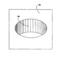
図2は、本発明による、図1からの基板ホールのうちの1つの一実施形態の拡大した斜視図である。ここでは、基板100内の1つのホール102が示される。
【0008】
図3は、本発明による、孔内壁面をめっきし、エッチングした後の図2の構造の一実施形態の斜視図である。孔内壁面をめっきした後に、ホール102は、ホール102を包囲し、ホール102を通って基板100の反対側に至る金属めっきのリング300を有する。この実施形態の金属めっきの領域300は円形であるが、他の形状の金属の領域300も本発明の範囲内で同じように良好に機能するであろう。たとえば、本発明の実施形態の中には、金属の領域300が楕円形、正方形、長方形あるいは他のより複雑な形状を有するものもある。金属めっきとして銅が好ましい材料ではあるが、本発明の他の例示的な実施形態は、めっきとして他の材料を用いる場合がある。
【0009】
図4は、本発明による、成形されたドームを追加した図3の構造の一実施形態の斜視図である。成形されたドーム400は、孔内壁面をめっきされたスルーホール102のうちの少なくともいくつかのホールに追加される。成形されたドーム400は、基板100の各側にあるめっきされたスルーホール102の一部、または全部に追加される場合があるか、全く追加されない場合がある。本発明の1つの例示的な実施形態では、成形されたドーム400は、基板の両側に追加され、二重超小型スパイダインターポーザが形成される。本明細書では、本発明に従って形成される特殊化された電気接点は、超小型スパイダ接点、あるいは単に超小型スパイダと呼ばれる。本発明の別の実施形態では、成形されたドーム400は、超小型スパイダ/ボールグリッドアレイ(BGA)ボールインターポーザを形成するために、基板100の片側にのみ追加される。
【0010】
図5は、本発明による、ドームが金属めっきされた後の図4の構造の一実施形態の斜視図である。図5の金属めっきされたドーム500は、設計要件に応じて、銅あるいは他の金属元素あるいは組成を含む場合がある。
【0011】
図6は、本発明による、マスク層を追加した後の図5の構造の一実施形態の斜視図である。ここでは、時計回り超小型スパイダの形のマスク層600が、金属めっきされたドーム500上に追加されている。マスク層はフォトレジストを含み、任意の数の方法によって被着される場合がある。フォトレジストは、超小型スパイダの形のマスク層600を形成するために露光され、現像される場合がある。
【0012】
図7は、本発明による、マスク層によって覆われない全ての領域内の金属層がエッチングされて除去された後の図6の構造の一実施形態の斜視図である。マスク層600で覆われる、エッチングされた超小型スパイダ700は、基板100上の成形されたドーム400上の適所に見られる。
【0013】
図8は、超小型スパイダ700からマスク層600が除去された後の図7の構造の一実施形態の斜視図である。
【0014】
図9は、本発明による、ドームが溶解された後の図8の構造の一実施形態の斜視図である。成形されたドーム400は、超小型スパイダ700、めっき300、ホール102あるいは基板100に損傷を与えることなく、ドーム材料を完全に除去することができる任意の化学薬品によって(あるいは他のエッチング法によって)溶解されることが好ましい。
【0015】
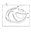
図10は、本発明による、図9からの超小型スパイダ接点構造の一実施形態の平面図である。1つの時計回り超小型スパイダ700が、基板100上の金属めっき300によって包囲されるスルーホール102上に示される。この時点で、超小型スパイダは、所望により、付加的な金属めっきのようなさらに別の処理にかけられる場合がある。また、本発明の他の実施形態では、所望により反時計回りの超小型スパイダが形成される場合があることにも留意されたい。たとえば、概ね等しい数の時計回りおよび反時計回りの超小型スパイダが形成されるような、超小型スパイダの大きなアレイを設計することが有利な場合がある。そのような設計は、時計回りのみ、あるいは反時計回りのみの超小型スパイダからなるアレイにおいて生じることになる回転トルクを低減することができる。超小型スパイダはそれぞれわずかに回動し、使用中に接点上にワイピング作用を生成するため、各超小型スパイダによって、それに接続される素子上に少量のトルクを生じる。
【0016】
結果として形成される超小型スパイダは、2001年7月27日に出願の「Electrical Contact」というタイトルの米国特許出願第09/917,361号にさらに記載される。超小型スパイダを製造するための別の方法が、2001年7月27日に出願の「Method for the Fabrication of Electrical Contacts」というタイトルの米国特許出願第09/917,357号にさらに記載される。
【0017】
図11は、本発明による、基板100上に示される時計回り超小型スパイダ700のアレイの一実施形態の斜視図である。上記のように、本発明のいくつかの実施形態では、時計回りおよび反時計回りの超小型スパイダを交互に、たとえば市松模様に配置することが望ましい場合がある。
【0018】
図12は、本発明による超小型スパイダインターポーザの断面図である。本発明のこの例示的な実施形態では、超小型スパイダは基板100の両側に構成される。超小型スパイダ700の各対には、めっきされたスルーホール102が接続される。各ホールを包囲する金属300は、個々の超小型スパイダに接続されているのがわかる。この例示的な実施形態は、基板100の上側に時計回りの超小型スパイダ700を、基板100の下側に反時計回りの超小型スパイダ700含むが、本発明の範囲内で他の構成も実現可能である。
【0019】
図13Aおよび図13Bは、本発明による1つの超小型スパイダインターポーザ対の実施形態の断面図である。図13Aには、基板100の上側に反時計回りの超小型スパイダ700が、基板100の下側に時計回りの超小型スパイダ700が示される。超小型スパイダ700の対は、めっきされたスルーホール102およびそのホールを包囲する金属300によって電気的に接続される。図13Bには、基板100の上側に時計回りの超小型スパイダ700が、基板100の下側に反時計回りの超小型スパイダ700が示される。超小型スパイダ700の対は、めっきされたスルーホール102およびそのホールを包囲する金属300によって電気的に接続される。
【0020】
図14は、本発明による、超小型係止手段1400に隣接する、基板100内のホール102を包囲する金属300に電気的に接続される1つの時計回り超小型スパイダ700の一実施形態の斜視図である。超小型係止手段1400は、使用中に超小型スパイダ700の過大な圧縮を防ぐように構成される隆起係止手段を形成するために、標準的なプリント回路基板プロセスに類似のプロセスを用いて構成される場合がある。超小型係止手段1400の高さによって、超小型スパイダ700を物理的に損傷することになる過大な圧縮を防ぎながら、超小型スパイダ700の圧縮および接点ワイピング作用を達成できることが好ましい。
【0021】
図15は、本発明による、図14からの構造の一実施形態の断面図である。本発明のこの例示的な実施形態では、一対の超小型係止手段1400を含む超小型スパイダインターポーザが断面図で示される。基板100の上側にある時計回りの超小型スパイダ700は、基板100内のめっきされたスルーホール102を包囲する金属300を通して、基板100の下側にある反時計回りの超小型スパイダ700に電気的に接続される。
【0022】
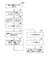
図16は、本発明による超小型スパイダ接点を形成する方法の流れ図である。ステップ1602では、基板100内に複数のホール102が形成される。ステップ1604では、ホール102は、その孔内壁面がめっきされて、エッチングされる。ステップ1606では、めっきされたスルーホール102上に、成形されたドームが形成される。ステップ1608では、成形されたドームによって覆われるホール102を有する基板100が金属めっきされる。ステップ1610では、金属めっきされたドーム上に、超小型スパイダの形のマスク層が形成される。ステップ1612では、マスク層によって覆われない全ての場所において、金属めっきがエッチングされて除去される。ステップ1614では、マスク層が除去される。ステップ1616では、ドームが溶解、あるいはエッチングされて、仕上げられた超小型スパイダが残される。そのプロセスのこの時点で、所望により、超小型スパイダは、ニッケルあるいは金のような1つあるいは複数の付加的な金属で再び金属めっきされる場合もある。オプションのステップ1618では、ボールグリッドアレイ(BGA)ボールが、基板100の超小型スパイダ700とは反対側のめっきされたスルーホール102上に配置される。本発明のそのような実施形態では、超小型スパイダ700が基板100の一方の側に配置され、BGAボール1900が基板100の他方の側に配置されて、超小型スパイダ/BGAインターポーザが形成される。
【0023】
図17は、本発明による、3つの脚部を有する超小型スパイダの一実施形態の斜視図である。基板100内のめっきされたスルーホール102を包囲する金属300に接続される、3つの脚部を有する超小型スパイダ1700が示される。超小型スパイダは、本発明の範囲内で、意図された用途によって望まれるように、任意の数(2つ以上)の脚部で構成される場合がある。
【0024】
図18は、本発明による、基板100上にある複数の、3つの脚部を有する超小型スパイダの一実施形態の斜視図である。図18は、基板上にある、3つの脚部を有する超小型スパイダ1700のアレイを示す。この図面は超小型スパイダ1700の規則的なアレイを示すが、本発明の他の実施形態は、複数の超小型スパイダ1700の意図された目的によって望まれるように、超小型スパイダ1700の不規則なアレイを用いる場合もある。
【0025】
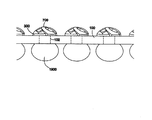
本発明の特定の例示的な実施形態では、超小型スパイダ700が基板100の第1の側に構成され、ボールグリッドアレイボール1900が基板100の第2の側に構成され、回路基板にマルチチップモジュール(MCM)のような電子装置を取外し可能に取り付ける際に用いるためのインターポーザを形成することが好ましい。図19は、そのような実施形態の断面図である。図19に示される本発明の例示的な実施形態は、超小型スパイダ700と接触する金属の領域104によって包囲されるめっきされたスルーホール102によって互いに接続される、基板の第1の側に構成される複数の超小型スパイダ700と、基板100の第2の側に構成されるボールグリッドアレイ(BGA)ボール1900とを示す。本発明のこの例示的な実施形態は、回路基板にMCMのような電子装置を取外し可能に取り付ける際に用いるためのインターポーザとして用いられる場合があり、一方、そのインターポーザはBGAボール1900によって回路基板に取り付けられる。本発明の例示的な実施形態は、オプションのステップ1618を含む図16に関連して記載されるプロセスを用いて製造することができる。
【0026】
本発明を、構造的と方法的特徴に関してある程度特定的な言葉で説明したが、本明細書に開示した手段は本発明を実施する好ましい形態を含むものであり、本発明はこれら図示し記載された特定の特徴に制限されないことを理解されたい。したがって、本発明は、均等の原則に従って適切に解釈される特許請求の範囲に記載された範囲内におけるいかなる形態または変更についても含むものである。
【0027】
本発明は以下に要約される。
【0028】
1. 電気接点を製造するための方法において、
a)基板(100)において複数のバイア(102)の孔内壁面をめっきするステップと、
b)前記めっきされたバイア(102)のうちの少なくともいくつかのバイアの上側にドーム(400)を形成するステップと、
c)前記ドーム(400)に対して第1の金属めっきを実施するステップと、
d)前記ドーム(400)をマスクするステップと、
e)前記マスクによって覆われない領域内の、前記ドーム(400)上の前記第1の金属めっきをエッチングして除去し、複数の電気接点(700)を形成するステップであって、前記電気接点(700)は、圧縮時に金属パッド上にワイピング作用を生成するように構成される螺旋状脚部を含むステップと、
f)前記ドーム(400)を溶解するステップと、
を備えることを特徴とする方法。
【0029】
2. 前記基板は、前記バイア(102)が前記基板(100)内に形成される前に、前記バイア(102)の概ね全ての場所を包囲する金属パッド(300)を含むことを特徴とする第1項に記載の電気接点を製造するための方法。
【0030】
3. g)第1の金属めっきを実施する前記ステップの後に、前記電気接点(700)に対して第2の金属めっきを実施するステップをさらに含むことを特徴とする第1項に記載の電気接点を製造するための方法。
【0031】
4. 前記第2の金属めっきは金を含むことを特徴とする第3項に記載の電気接点を製造するための方法。
【0032】
5. 前記第2の金属めっきは、ニッケルおよび金を含むことを特徴とする第3項に記載の電気接点を製造するための方法。
【0033】
6. 前記第1の金属めっきは銅であることを特徴とする第1項に記載の電気接点を製造するための方法。
【0034】
7. 前記基板(100)は、プリント回路基板(100)であることを特徴とする第1項に記載の電気接点を製造するための方法。
【0035】
8. 前記電気接点(700)のうちの少なくともいくつかの接点は、前記基板(100)の反対側にあることを特徴とする第1項に記載の電気接点を製造するための方法。
【0036】
9. g)前記基板(100)の前記電気接点(700)と反対側にある前記壁面めっきされたスルーホール(102)に、複数のボールグリッドアレイボール(1900)を追加するステップ、
をさらに含むことを特徴とする第1項に記載の電気接点を製造するための方法。
【0037】
10. i)前記基板(100)上に少なくとも1つの超小型係止手段(1400)を形成するステップ、
をさらに含むことを特徴とする第1項に記載の電気接点を製造するための方法。
【0038】
【発明の効果】
上記のように、本発明によれば、インターポーザとして用いることができる超小型電気接点を実現することができる。
【図面の簡単な説明】
【図1】本発明による、ホールのアレイを含む基板の一実施形態の斜視図である。
【図2】本発明による、図1の基板ホールのうちの1つの一実施形態の拡大した斜視図である。
【図3】本発明による、貫通してめっきし、エッチングした後の図2の構造の一実施形態の斜視図である。
【図4】本発明による、成形されたドームを追加した図3の構造の一実施形態の斜視図である。
【図5】本発明による、ドームが金属めっきされた後の図4の構造の一実施形態の斜視図である。
【図6】本発明による、マスク層を加えた後の図5の構造の一実施形態の斜視図である。
【図7】本発明による、マスク層によって覆われない全ての領域内の金属層がエッチングによって除去された後の図6の構造の一実施形態の斜視図である。
【図8】本発明による、マスク層が除去された後の図7の構造の一実施形態の斜視図である。
【図9】本発明による、ドームが溶解された後の図8の構造の一実施形態の斜視図である。
【図10】本発明による、図9からの最終的な超小型スパイダ接点の一実施形態の平面図である。
【図11】本発明による時計回りの超小型スパイダのアレイの一実施形態の斜視図である。
【図12】本発明による超小型スパイダインターポーザの一実施形態の断面図である。
【図13】AおよびBは、それぞれ本発明による1つの超小型スパイダインターポーザ対の実施形態の断面図である。
【図14】本発明による、1つの時計回り超小型スパイダおよび1つの超小型係止手段の一実施形態の図である。
【図15】本発明による、図14からの構造の一実施形態の断面図である。
【図16】本発明による超小型スパイダ接点を形成するための方法の流れ図である。
【図17】3つの脚部を有する超小型スパイダの一実施形態の斜視図である。
【図18】本発明による、基板上の複数の、3つの脚部を有する超小型スパイダの一実施形態の斜視図である。
【図19】本発明による超小型スパイダ/ボールグリッドアレイインターポーザの一実施形態の断面図である。
【符号の説明】
100 基板
102 バイア、スルーホール
400 ドーム
700 電気接点
1400 超小型係止手段
1900 ボールグリッドアレイボール[0001]
BACKGROUND OF THE INVENTION
The present invention relates generally to the field of electrical contacts, and more specifically to a method for manufacturing electrical contacts.
[0002]
[Prior art]
Existing electrical contact designs include an interposer constructed from an elastic material and an interposer constructed from a wire ball. Both of these solutions have inherent limitations with respect to their design. Current elastic materials are unable to retain sufficient contact elastic force over time and temperature, and their operating height range is small. Interposers composed of wire balls are fragile, tend to disassemble, may require expensive inspection, and have a limited amount of contact stroke.
[0003]
[Problems to be solved by the invention]
An object of the present invention is to solve the conventional problems and provide an ultra-small electrical contact that can be used as an interposer.
[0004]
[Means for Solving the Problems]
A method is provided for manufacturing electrical contacts using metal forming, masking, etching and soldering techniques. The method can be used in interposers or other devices and includes a number of specialized, including temporary or permanent electrical contacts that provide contact wiping, soft spring rate, durability and very long strokes. Manufacture electrical contacts.
[0005]
Other aspects and advantages of the invention will become apparent from the following detailed description, taken in conjunction with the accompanying drawings, illustrating by way of example the principles of the invention.
[0006]
DETAILED DESCRIPTION OF THE INVENTION
FIG. 1 is a perspective view of one embodiment of a substrate including an array of holes in accordance with the present invention. A number of holes or
[0007]
FIG. 2 is an enlarged perspective view of one embodiment of one of the substrate holes from FIG. 1 according to the present invention. Here, one
[0008]
FIG. 3 is a perspective view of one embodiment of the structure of FIG. 2 after plating and etching the hole inner wall according to the present invention. After plating the inner wall surface of the hole, the
[0009]
FIG. 4 is a perspective view of one embodiment of the structure of FIG. 3 with the addition of a shaped dome according to the present invention. The molded
[0010]
FIG. 5 is a perspective view of one embodiment of the structure of FIG. 4 after the dome has been metal plated according to the present invention. The metal
[0011]
FIG. 6 is a perspective view of one embodiment of the structure of FIG. 5 after adding a mask layer according to the present invention. Here, a
[0012]
FIG. 7 is a perspective view of one embodiment of the structure of FIG. 6 after the metal layer in all areas not covered by the mask layer has been etched away according to the present invention. An etched
[0013]
FIG. 8 is a perspective view of one embodiment of the structure of FIG. 7 after the
[0014]
FIG. 9 is a perspective view of one embodiment of the structure of FIG. 8 after the dome has been melted in accordance with the present invention. The
[0015]
10 is a plan view of one embodiment of a micro spider contact structure from FIG. 9 in accordance with the present invention. One clockwise
[0016]
The resulting micro-spider is further described in US patent application Ser. No. 09 / 917,361 entitled “Electrical Contact” filed Jul. 27, 2001. Another method for manufacturing micro spiders is further described in US patent application Ser. No. 09 / 917,357, entitled “Method for the Fabrication of Electrical Contacts”, filed July 27, 2001.
[0017]
FIG. 11 is a perspective view of one embodiment of an array of
[0018]
FIG. 12 is a cross-sectional view of a microminiature spider interposer according to the present invention. In this exemplary embodiment of the invention, micro spiders are configured on both sides of the
[0019]
13A and 13B are cross-sectional views of one microspider interposer pair embodiment according to the present invention. FIG. 13A shows a counterclockwise
[0020]
FIG. 14 is a perspective view of one embodiment of one clockwise
[0021]
15 is a cross-sectional view of one embodiment of the structure from FIG. 14, in accordance with the present invention. In this exemplary embodiment of the invention, a micro spider interposer including a pair of micro locking means 1400 is shown in cross-section. The clockwise
[0022]
FIG. 16 is a flow diagram of a method of forming a micro spider contact according to the present invention. In
[0023]
FIG. 17 is a perspective view of one embodiment of a micro spider having three legs according to the present invention. A
[0024]
FIG. 18 is a perspective view of one embodiment of a micro spider having a plurality of three legs on a
[0025]
In a particular exemplary embodiment of the present invention, the
[0026]
Although the present invention has been described in certain terms with regard to structural and methodological features, the means disclosed herein include preferred forms of practicing the invention, and the invention is illustrated and described. It should be understood that the invention is not limited to specific features. Accordingly, the present invention includes any forms or modifications within the scope of the claims as appropriately interpreted in accordance with the principle of equality.
[0027]
The present invention is summarized below.
[0028]
1. In a method for manufacturing an electrical contact,
a) plating the inner wall surface of the plurality of vias (102) on the substrate (100);
b) forming a dome (400) on top of at least some of the plated vias (102);
c) performing a first metal plating on the dome (400);
d) masking the dome (400);
e) etching away the first metal plating on the dome (400) in a region not covered by the mask to form a plurality of electrical contacts (700), the electrical contacts (700) includes a helical leg configured to create a wiping action on the metal pad upon compression;
f) dissolving the dome (400);
A method comprising the steps of:
[0029]
2. The substrate includes a metal pad (300) that surrounds substantially all locations of the via (102) before the via (102) is formed in the substrate (100). A method for manufacturing the electrical contact according to item.
[0030]
3. g) after the step of performing a first metal plating, further comprising the step of performing a second metal plating on the electrical contact (700); Method for manufacturing.
[0031]
4). 4. The method for manufacturing an electrical contact according to claim 3, wherein the second metal plating includes gold.
[0032]
5. The method for manufacturing an electrical contact according to claim 3, wherein the second metal plating includes nickel and gold.
[0033]
6). The method for manufacturing an electrical contact according to claim 1, wherein the first metal plating is copper.
[0034]
7). The method for manufacturing an electrical contact according to claim 1, wherein the substrate (100) is a printed circuit board (100).
[0035]
8). The method for manufacturing an electrical contact according to claim 1, wherein at least some of the electrical contacts (700) are on opposite sides of the substrate (100).
[0036]
9. g) adding a plurality of ball grid array balls (1900) to the wall plated through holes (102) opposite the electrical contacts (700) of the substrate (100);
The method for manufacturing an electrical contact according to claim 1, further comprising:
[0037]
10. i) forming at least one microminiature locking means (1400) on said substrate (100);
The method for manufacturing an electrical contact according to claim 1, further comprising:
[0038]
【The invention's effect】
As described above, according to the present invention, a micro electrical contact that can be used as an interposer can be realized.
[Brief description of the drawings]
FIG. 1 is a perspective view of one embodiment of a substrate including an array of holes in accordance with the present invention.
2 is an enlarged perspective view of one embodiment of one of the substrate holes of FIG. 1 in accordance with the present invention.
FIG. 3 is a perspective view of one embodiment of the structure of FIG. 2 after being plated through and etched in accordance with the present invention.
4 is a perspective view of one embodiment of the structure of FIG. 3 with the addition of a shaped dome according to the present invention.
5 is a perspective view of one embodiment of the structure of FIG. 4 after the dome has been metal plated according to the present invention.
6 is a perspective view of one embodiment of the structure of FIG. 5 after the addition of a mask layer according to the present invention.
7 is a perspective view of one embodiment of the structure of FIG. 6 after etching away the metal layer in all areas not covered by the mask layer according to the present invention.
FIG. 8 is a perspective view of one embodiment of the structure of FIG. 7 after the mask layer has been removed, according to the present invention.
FIG. 9 is a perspective view of one embodiment of the structure of FIG. 8 after the dome has been melted, according to the present invention.
10 is a plan view of one embodiment of the final micro spider contact from FIG. 9, in accordance with the present invention.
FIG. 11 is a perspective view of one embodiment of an array of clockwise micro spiders according to the present invention.
FIG. 12 is a cross-sectional view of one embodiment of a micro spider interposer according to the present invention.
FIGS. 13A and 13B are cross-sectional views of one microspider interposer pair embodiment according to the present invention, respectively.
FIG. 14 is a diagram of one embodiment of a clockwise micro spider and a micro locking means according to the present invention.
15 is a cross-sectional view of one embodiment of the structure from FIG. 14, in accordance with the present invention.
FIG. 16 is a flow diagram of a method for forming a micro spider contact according to the present invention.
FIG. 17 is a perspective view of one embodiment of a micro spider having three legs.
FIG. 18 is a perspective view of one embodiment of a micro spider having a plurality of three legs on a substrate in accordance with the present invention.
FIG. 19 is a cross-sectional view of one embodiment of a microminiature spider / ball grid array interposer according to the present invention.
[Explanation of symbols]
DESCRIPTION OF
Claims (9)
a)基板において複数のバイアの孔内壁面をめっきするステップと、
b)前記めっきされたバイアのうちの少なくともいくつかのバイアの上側にドームを形成するステップと、
c)前記ドームに対して第1の金属めっきを実施するステップと、
d)前記ドームをマスクするステップと、
e)前記マスクによって覆われない領域内の、前記ドーム上の前記第1の金属めっきをエッチングして除去し、複数の電気接点を形成するステップであって、前記電気接点は、圧縮時に前記電気接点上にワイピング作用を生成するように構成される螺旋状脚部を含むステップと、
f)前記ドームを溶解するステップと、
を備える電気接点を製造するための方法。In a method for manufacturing an electrical contact,
a) plating a hole inner wall surface of a plurality of vias on the substrate;
b) forming a dome above at least some of the plated vias;
c) performing a first metal plating on the dome;
d) masking the dome;
e) etching away the first metal plating on the dome in a region not covered by the mask to form a plurality of electrical contacts, the electrical contacts being Including a helical leg configured to create a wiping action on the contact;
f) dissolving the dome;
A method for manufacturing an electrical contact comprising:
g)前記電気接点に対して第2の金属めっきを実施するステップをさらに含むことを特徴とする請求項1に記載の電気接点を製造するための方法。After performing the first metal plating,
The method for manufacturing an electrical contact according to claim 1, further comprising the step of g) performing a second metal plating on the electrical contact.
g)前記電気接点に対して第2の金属めっきを実施するステップをさらに含むことを特徴とする請求項1に記載の電気接点を製造するための方法。After the step of melting the dome,
The method for manufacturing an electrical contact according to claim 1, further comprising the step of g) performing a second metal plating on the electrical contact.
g)前記マスクを除去するステップをさらに含むことを特徴とする請求項1に記載の電気接点を製造するための方法。After the step including the helical leg,
The method for manufacturing an electrical contact according to claim 1, further comprising the step of g) removing the mask.
Applications Claiming Priority (2)
| Application Number | Priority Date | Filing Date | Title |
|---|---|---|---|
| US09/917093 | 2001-07-27 | ||
| US09/917,093 US6627092B2 (en) | 2001-07-27 | 2001-07-27 | Method for the fabrication of electrical contacts |
Publications (3)
| Publication Number | Publication Date |
|---|---|
| JP2003078075A JP2003078075A (en) | 2003-03-14 |
| JP2003078075A5 JP2003078075A5 (en) | 2005-04-21 |
| JP4163458B2 true JP4163458B2 (en) | 2008-10-08 |
Family
ID=25438336
Family Applications (1)
| Application Number | Title | Priority Date | Filing Date |
|---|---|---|---|
| JP2002203964A Expired - Fee Related JP4163458B2 (en) | 2001-07-27 | 2002-07-12 | Method for manufacturing electrical contacts |
Country Status (6)
| Country | Link |
|---|---|
| US (1) | US6627092B2 (en) |
| JP (1) | JP4163458B2 (en) |
| CN (1) | CN1266759C (en) |
| DE (1) | DE10231172A1 (en) |
| GB (1) | GB2383188B (en) |
| SG (1) | SG104332A1 (en) |
Families Citing this family (30)
| Publication number | Priority date | Publication date | Assignee | Title |
|---|---|---|---|---|
| JP3950799B2 (en) * | 2003-01-28 | 2007-08-01 | アルプス電気株式会社 | Connected device |
| TW559328U (en) * | 2003-03-25 | 2003-10-21 | P Two Ind Inc | Metal leaf spring structure |
| US7005751B2 (en) * | 2003-04-10 | 2006-02-28 | Formfactor, Inc. | Layered microelectronic contact and method for fabricating same |
| US6948940B2 (en) * | 2003-04-10 | 2005-09-27 | Formfactor, Inc. | Helical microelectronic contact and method for fabricating same |
| US20070020960A1 (en) * | 2003-04-11 | 2007-01-25 | Williams John D | Contact grid array system |
| US7056131B1 (en) * | 2003-04-11 | 2006-06-06 | Neoconix, Inc. | Contact grid array system |
| US8584353B2 (en) | 2003-04-11 | 2013-11-19 | Neoconix, Inc. | Method for fabricating a contact grid array |
| US7114961B2 (en) | 2003-04-11 | 2006-10-03 | Neoconix, Inc. | Electrical connector on a flexible carrier |
| US7244125B2 (en) * | 2003-12-08 | 2007-07-17 | Neoconix, Inc. | Connector for making electrical contact at semiconductor scales |
| US7113408B2 (en) * | 2003-06-11 | 2006-09-26 | Neoconix, Inc. | Contact grid array formed on a printed circuit board |
| US20050120553A1 (en) * | 2003-12-08 | 2005-06-09 | Brown Dirk D. | Method for forming MEMS grid array connector |
| US6916181B2 (en) * | 2003-06-11 | 2005-07-12 | Neoconix, Inc. | Remountable connector for land grid array packages |
| US7758351B2 (en) | 2003-04-11 | 2010-07-20 | Neoconix, Inc. | Method and system for batch manufacturing of spring elements |
| JP2004345286A (en) * | 2003-05-23 | 2004-12-09 | Sony Corp | Method for decorating surface of mold, and mold |
| TWI343156B (en) * | 2003-10-16 | 2011-06-01 | Tyco Electronics Corp | Conductive elastomeric contact system with anti-overstress columns |
| US6890185B1 (en) * | 2003-11-03 | 2005-05-10 | Kulicke & Soffa Interconnect, Inc. | Multipath interconnect with meandering contact cantilevers |
| JP4520874B2 (en) * | 2004-02-06 | 2010-08-11 | 矢崎総業株式会社 | Female terminals and connectors |
| US7137831B2 (en) * | 2004-03-16 | 2006-11-21 | Alps Electric Co., Ltd. | Substrate having spiral contactors |
| US7090503B2 (en) | 2004-03-19 | 2006-08-15 | Neoconix, Inc. | Interposer with compliant pins |
| US7025601B2 (en) * | 2004-03-19 | 2006-04-11 | Neoconix, Inc. | Interposer and method for making same |
| WO2005091998A2 (en) | 2004-03-19 | 2005-10-06 | Neoconix, Inc. | Electrical connector in a flexible host |
| JP2006049101A (en) * | 2004-08-05 | 2006-02-16 | Molex Japan Co Ltd | Sheet-shaped connector and its manufacturing method |
| US7262495B2 (en) * | 2004-10-07 | 2007-08-28 | Hewlett-Packard Development Company, L.P. | 3D interconnect with protruding contacts |
| JP2006253580A (en) * | 2005-03-14 | 2006-09-21 | Alps Electric Co Ltd | Electronic function component packaging body and electronic apparatus |
| JP2006351327A (en) * | 2005-06-15 | 2006-12-28 | Alps Electric Co Ltd | Connection structure of members, its manufacturing method, and electronic equipment having connection structure of members |
| US7331796B2 (en) * | 2005-09-08 | 2008-02-19 | International Business Machines Corporation | Land grid array (LGA) interposer utilizing metal-on-elastomer hemi-torus and other multiple points of contact geometries |
| CN101517734A (en) * | 2006-09-26 | 2009-08-26 | 阿尔卑斯电气株式会社 | Elastic contact and method for bonding between metal terminals using the same |
| US8641428B2 (en) | 2011-12-02 | 2014-02-04 | Neoconix, Inc. | Electrical connector and method of making it |
| US9680273B2 (en) | 2013-03-15 | 2017-06-13 | Neoconix, Inc | Electrical connector with electrical contacts protected by a layer of compressible material and method of making it |
| DE102015004151B4 (en) * | 2015-03-31 | 2022-01-27 | Feinmetall Gmbh | Method for manufacturing a spring contact pin arrangement with several spring contact pins |
Family Cites Families (14)
| Publication number | Priority date | Publication date | Assignee | Title |
|---|---|---|---|---|
| JPS5285362A (en) * | 1976-01-09 | 1977-07-15 | Hitachi Ltd | Method of producing connecting terminal of ceramic wiring substrate |
| US5366380A (en) * | 1989-06-13 | 1994-11-22 | General Datacomm, Inc. | Spring biased tapered contact elements for electrical connectors and integrated circuit packages |
| WO1991000619A1 (en) | 1989-06-30 | 1991-01-10 | Raychem Corporation | Flying leads for integrated circuits |
| US5228861A (en) * | 1992-06-12 | 1993-07-20 | Amp Incorporated | High density electrical connector system |
| US6029344A (en) * | 1993-11-16 | 2000-02-29 | Formfactor, Inc. | Composite interconnection element for microelectronic components, and method of making same |
| US5802699A (en) | 1994-06-07 | 1998-09-08 | Tessera, Inc. | Methods of assembling microelectronic assembly with socket for engaging bump leads |
| JPH08287983A (en) | 1995-04-14 | 1996-11-01 | Whitaker Corp:The | Elastomer connector |
| US6007349A (en) * | 1996-01-04 | 1999-12-28 | Tessera, Inc. | Flexible contact post and post socket and associated methods therefor |
| JPH10197557A (en) * | 1997-01-14 | 1998-07-31 | Toppan Printing Co Ltd | Inspection member and manufacture thereof |
| JPH10261473A (en) * | 1997-03-19 | 1998-09-29 | Hitachi Electron Eng Co Ltd | Ic socket |
| JP2001116795A (en) * | 1999-10-18 | 2001-04-27 | Mitsubishi Electric Corp | Test socket and connection sheet for use in test socket |
| US6442039B1 (en) * | 1999-12-03 | 2002-08-27 | Delphi Technologies, Inc. | Metallic microstructure springs and method of making same |
| JP3440243B2 (en) * | 2000-09-26 | 2003-08-25 | 株式会社アドバンストシステムズジャパン | Spiral contactor |
| US6558560B2 (en) * | 2001-07-27 | 2003-05-06 | Hewlett-Packard Company | Method for the fabrication of electrical contacts |
-
2001
- 2001-07-27 US US09/917,093 patent/US6627092B2/en not_active Expired - Lifetime
-
2002
- 2002-05-28 SG SG200203167A patent/SG104332A1/en unknown
- 2002-07-10 DE DE10231172A patent/DE10231172A1/en not_active Withdrawn
- 2002-07-10 GB GB0216021A patent/GB2383188B/en not_active Expired - Fee Related
- 2002-07-12 JP JP2002203964A patent/JP4163458B2/en not_active Expired - Fee Related
- 2002-07-26 CN CN02127069.4A patent/CN1266759C/en not_active Expired - Fee Related
Also Published As
| Publication number | Publication date |
|---|---|
| CN1400697A (en) | 2003-03-05 |
| JP2003078075A (en) | 2003-03-14 |
| US6627092B2 (en) | 2003-09-30 |
| CN1266759C (en) | 2006-07-26 |
| GB2383188B (en) | 2004-10-27 |
| GB0216021D0 (en) | 2002-08-21 |
| SG104332A1 (en) | 2004-06-21 |
| GB2383188A (en) | 2003-06-18 |
| DE10231172A1 (en) | 2003-02-20 |
| US20030019836A1 (en) | 2003-01-30 |
Similar Documents
| Publication | Publication Date | Title |
|---|---|---|
| JP4163458B2 (en) | Method for manufacturing electrical contacts | |
| US6558560B2 (en) | Method for the fabrication of electrical contacts | |
| JP2003100963A (en) | Electric contact | |
| US6007349A (en) | Flexible contact post and post socket and associated methods therefor | |
| TW463272B (en) | Resin-encapsulated semiconductor device | |
| JP4294078B1 (en) | Double-sided connector | |
| JP2003124404A5 (en) | ||
| TW567599B (en) | Wafer level package with air pads and manufacturing method thereof | |
| JP2003078075A5 (en) | ||
| US7651886B2 (en) | Semiconductor device and manufacturing process thereof | |
| JP4607390B2 (en) | Solder ball suction mask and manufacturing method thereof | |
| JP2011096819A (en) | Semiconductor apparatus and circuit board | |
| KR20010078779A (en) | Semiconductor device using a BGA package and method of producing the same | |
| JP2009054969A (en) | Wiring board and manufacturing method thereof | |
| JP2005286331A (en) | Minute bump for improving lga interconnection | |
| JPH11289141A (en) | Circuit board and its manufacture | |
| KR100439407B1 (en) | Method of producing a semiconductor device package | |
| JP4033811B2 (en) | Flip chip mounting body | |
| JP3800298B2 (en) | Bump forming method and semiconductor device manufacturing method | |
| JP4286965B2 (en) | Wiring member manufacturing method | |
| TWI595575B (en) | Micro mechanical anchor for 3d architecture | |
| JPH08330472A (en) | Semiconductor device and its manufacture | |
| JP2009076564A5 (en) | ||
| KR100375248B1 (en) | Method for mounting a semiconductor chip on a substrate, and semiconductor device adapted for mounting on a substrate | |
| KR20130049055A (en) | A method of manufacturing metal post and a printed circuit board including the same |
Legal Events
| Date | Code | Title | Description |
|---|---|---|---|
| A521 | Request for written amendment filed |
Free format text: JAPANESE INTERMEDIATE CODE: A523 Effective date: 20040615 |
|
| A621 | Written request for application examination |
Free format text: JAPANESE INTERMEDIATE CODE: A621 Effective date: 20040615 |
|
| A977 | Report on retrieval |
Free format text: JAPANESE INTERMEDIATE CODE: A971007 Effective date: 20070910 |
|
| A131 | Notification of reasons for refusal |
Free format text: JAPANESE INTERMEDIATE CODE: A131 Effective date: 20070918 |
|
| A521 | Request for written amendment filed |
Free format text: JAPANESE INTERMEDIATE CODE: A523 Effective date: 20071206 |
|
| A131 | Notification of reasons for refusal |
Free format text: JAPANESE INTERMEDIATE CODE: A131 Effective date: 20080422 |
|
| A521 | Request for written amendment filed |
Free format text: JAPANESE INTERMEDIATE CODE: A523 Effective date: 20080530 |
|
| TRDD | Decision of grant or rejection written | ||
| A01 | Written decision to grant a patent or to grant a registration (utility model) |
Free format text: JAPANESE INTERMEDIATE CODE: A01 Effective date: 20080624 |
|
| A01 | Written decision to grant a patent or to grant a registration (utility model) |
Free format text: JAPANESE INTERMEDIATE CODE: A01 |
|
| A61 | First payment of annual fees (during grant procedure) |
Free format text: JAPANESE INTERMEDIATE CODE: A61 Effective date: 20080724 |
|
| FPAY | Renewal fee payment (event date is renewal date of database) |
Free format text: PAYMENT UNTIL: 20110801 Year of fee payment: 3 |
|
| R150 | Certificate of patent or registration of utility model |
Free format text: JAPANESE INTERMEDIATE CODE: R150 |
|
| FPAY | Renewal fee payment (event date is renewal date of database) |
Free format text: PAYMENT UNTIL: 20110801 Year of fee payment: 3 |
|
| FPAY | Renewal fee payment (event date is renewal date of database) |
Free format text: PAYMENT UNTIL: 20120801 Year of fee payment: 4 |
|
| FPAY | Renewal fee payment (event date is renewal date of database) |
Free format text: PAYMENT UNTIL: 20130801 Year of fee payment: 5 |
|
| FPAY | Renewal fee payment (event date is renewal date of database) |
Free format text: PAYMENT UNTIL: 20130801 Year of fee payment: 5 |
|
| S111 | Request for change of ownership or part of ownership |
Free format text: JAPANESE INTERMEDIATE CODE: R313113 |
|
| FPAY | Renewal fee payment (event date is renewal date of database) |
Free format text: PAYMENT UNTIL: 20130801 Year of fee payment: 5 |
|
| R360 | Written notification for declining of transfer of rights |
Free format text: JAPANESE INTERMEDIATE CODE: R360 |
|
| R360 | Written notification for declining of transfer of rights |
Free format text: JAPANESE INTERMEDIATE CODE: R360 |
|
| R371 | Transfer withdrawn |
Free format text: JAPANESE INTERMEDIATE CODE: R371 |
|
| FPAY | Renewal fee payment (event date is renewal date of database) |
Free format text: PAYMENT UNTIL: 20130801 Year of fee payment: 5 |
|
| S111 | Request for change of ownership or part of ownership |
Free format text: JAPANESE INTERMEDIATE CODE: R313113 |
|
| FPAY | Renewal fee payment (event date is renewal date of database) |
Free format text: PAYMENT UNTIL: 20130801 Year of fee payment: 5 |
|
| R350 | Written notification of registration of transfer |
Free format text: JAPANESE INTERMEDIATE CODE: R350 |
|
| R250 | Receipt of annual fees |
Free format text: JAPANESE INTERMEDIATE CODE: R250 |
|
| LAPS | Cancellation because of no payment of annual fees |