JP4163358B2 - Groundwater flow measurement device - Google Patents
Groundwater flow measurement device Download PDFInfo
- Publication number
- JP4163358B2 JP4163358B2 JP2000004475A JP2000004475A JP4163358B2 JP 4163358 B2 JP4163358 B2 JP 4163358B2 JP 2000004475 A JP2000004475 A JP 2000004475A JP 2000004475 A JP2000004475 A JP 2000004475A JP 4163358 B2 JP4163358 B2 JP 4163358B2
- Authority
- JP
- Japan
- Prior art keywords
- current
- float
- flow
- electrodes
- measurement case
- Prior art date
- Legal status (The legal status is an assumption and is not a legal conclusion. Google has not performed a legal analysis and makes no representation as to the accuracy of the status listed.)
- Expired - Lifetime
Links
Images


Classifications
-
- Y—GENERAL TAGGING OF NEW TECHNOLOGICAL DEVELOPMENTS; GENERAL TAGGING OF CROSS-SECTIONAL TECHNOLOGIES SPANNING OVER SEVERAL SECTIONS OF THE IPC; TECHNICAL SUBJECTS COVERED BY FORMER USPC CROSS-REFERENCE ART COLLECTIONS [XRACs] AND DIGESTS
- Y02—TECHNOLOGIES OR APPLICATIONS FOR MITIGATION OR ADAPTATION AGAINST CLIMATE CHANGE
- Y02A—TECHNOLOGIES FOR ADAPTATION TO CLIMATE CHANGE
- Y02A90/00—Technologies having an indirect contribution to adaptation to climate change
- Y02A90/30—Assessment of water resources
Description
【0001】
【発明の属する技術分野】
本発明は、地下水の流速や流向をフロートの移動速度や方向により測定するフロート式の地下水流測定装置に関し、特に比較的流速の速い地下水流の測定に適した地下水流測定装置に関する。
【0002】
【従来の技術】
単孔式の地下水流測定方法として、従来、薬液や染料などのトレーサを測定ケース内に流入し、そのトレーサの流下方向や位置を測定して水流の流速や流向を測定するトレーサ方式、或は測定ケース内にビデオカメラを挿入し浮遊物を測定ケースに流入させてその動きを測定するカメラ法などが知られている。
【0003】
【発明が解決しようとする課題】
しかし、ビデオカメラを使用するカメラ法は、装置が大形化すると共に、カメラの前方をライトにより明るく照明するため、ライトによって水温が部分的に上昇し、対流が発生して地下水流の正確な動きを測定しにくくする問題があった。
【0004】
トレーサ方式は、現在、多く実施され、地下水流の動向をかなりの精度で測定することができるが、水流の動きが非常に遅く、水が自由に動き得る状態の場合、トレーサを水中に注入することによって、水が不安定に移動したり、注入液の拡散現象のため、高精度の地下水流の測定ができにくい問題があった。
【0005】
また、トレーサを注入する方式は、一度トレーサを注入して測定を行った後、再度測定を行いたい場合には、測定ケースをボーリング孔から引き上げてトレーサを充填しなおす必要があり、連続した測定ができない課題があった。
【0006】
そこで、従来、測定ケースを水中に入れ、その上部に空気層を形成した状態で、絶縁体のフロートを測定ケースの中央位置に浮遊させ、測定ケースの内周壁に90度の間隔で4個の電極を配設し、測定ケース内におけるフロートの位置に応じて変化する隣接電極間の電気抵抗の変化に基づき、フロートの位置を計時的に測定し、地下水流によって動くフロートの方向と速度を、地下水流の流向と流速として測定する装置が開発されている。
【0007】
このフロート式の地下水流測定装置は、通常、測定ケース内でのフロートの移動範囲が約5mmに形成され、フロートの位置に応じて変化する隣接電極間の電気抵抗の変化に基づき、フロートの位置を計時的に測定し、地下水流によって動くフロートの方向と速度を、地下水流の流向と流速として測定する。このような地下水流測定装置では、流速が1日当り約9m〜0.9m/日の比較的遅い流速の地下水流を測定する場合に、問題なく流速を正確に測定することができるものの、河川の近くでの測定、或は地下水汲み上げ付近での測定で、流速が例えば数十m〜数百m/日と非常に速い場合、流速測定値の誤差が非常に大きくなる問題があった。
【0008】
即ち、地下水流測定用の井戸のボーリング径は、通常66mm〜116mmであるが、そのボーリング孔壁を保護するためにパイプを挿入して観測井とし、その観測井に挿入する筒状の測定装置の内部つまりフロートが移動可能な範囲は、中心から10mm程度であり、また、中心付近または周辺付近の不安定領域を除くと、流速測定に使用可能なフロートの移動範囲は、約5mm程度に制限されてしまう。このため、流速が例えば数十m〜数百m/日と非常に速い場合、流速測定値の誤差が非常に大きくなる問題があった。
【0009】
ところで、測定装置を大型化すれば、当然、フロートの移動範囲を大きく採ることができるが、その場合には、ボーリング孔を大きくする必要があること、及び流速によって異なる測定装置が必要となること等から、施工性や経済性を悪化させる恐れが予想される。
【0010】
本発明は、上記の点に鑑みてなされたもので、流速の比較的速い地下水流を安定して正確に測定することができる地下水流測定装置を提供することを目的とする。
【0011】
【課題を解決するための手段】
上記目的を達成するために、本発明の地下水流測定装置は、地下水を流通可能な流通口を有する測定ケースと、測定ケース内に配置された絶縁体のフロートと、測定ケース内に空気を供給する空気供給手段と、測定ケースの内周壁に、測定ケースの横断面を平面とするX・Y平面上のX軸とY軸上に位置して配設された2対の電極と、X軸上に位置する一対の電極X1、X2とY軸上に位置する一対の電極Y1、Y2との間に、一定の電流を供給する定電流回路と、定電流回路からの電流供給時に各電極に流れる電流を検出すると共に、X軸上に位置する一対の電極X1、X2の電流値の差とY軸上に位置する一対の電極Y1、Y2の電流値の差とを演算して、該フロートの位置を示すX座標信号とY座標信号を発生するX・Y座標信号発生手段と、X・Y座標信号発生手段からのX座標信号とY座標信号に基づき、フロートの移動方向と移動速度を演算する演算処理手段と、フロートに取付けられた導体と、導体の周囲位置の測定ケースの内側に配設され、導体に誘導電流を生じさせる電磁誘導コイルと、電磁誘導コイルに交流電流を供給し制御する電流制御手段と、電流制御手段によりフロートに水流の向きと相反する電磁力を生じさせ、交流電流の値に基づき地下水流の流速を算出する流速算出手段と、を備え、電流制御手段は、電磁誘導コイルに電流を供給してフロートをセンタリングさせた状態で、その電流を徐々に低下させ、流速算出手段は、フロートの移動開始時の電流値に基づき、地下水流の流速を算出することを特徴とする。
【0012】
ここで、流速算出手段は、電流制御手段が電磁誘導コイルに電流を供給してフロートに水流の向きに相反する電磁力を生じさせてフロートをセンタリングさせる際の電流値とフロートの移動速度に基づき、地下水流の流速を算出するように構成することができる。
【0013】
【作用】
上記構成の地下水流測定装置は、測定時、先ず、測定ケース内にフロートを浮遊させた状態で、電磁誘導コイルに交流電流を供給し、電磁誘導コイルの内側に位置するフロートの導体に、中央に向う電磁力を生じさせ、フロートのセンタリングを行なう。センタリングした状態で、電流制御手段はフロートに水流の向きと相反する方向の電磁力を生じさせているが、この後、電磁誘導コイルの電流を徐々に低下させていく。そして、流速算出手段は、フロートが電磁力の低下により移動を開始する時点の電流値を取り込み、この電流値に基づき地下水流の流速を算出する。
【0014】
このように、フロートが水流により移動する際の速度を測定する代わりに、フロートが受ける水流の力に対応したセンタリングの電磁力つまり電磁誘導コイルに流す電流値に基づき流速を算出するので、流速が比較的速く、狭いフロートの移動範囲で正確な流速が測定できない場合であっても、このセンタリングの電磁力つまり電磁誘導コイルに流す電流値により、水流の流速を正確に算出することができる。
【0015】
一方、水流の流向は、流速を測定した後、電磁誘導コイルの電流を遮断して電磁力を消失させ、その状態で水流により移動するフロートの位置(方向)を、X・Y座標信号発生手段と演算処理手段を用いて算出する。X・Y座標信号発生手段は、定電流回路からの電流供給時に各電極に流れる電流を検出すると共に、X軸上に位置する一対の電極X1、X2の電流値の差とY軸上に位置する一対の電極Y1、Y2の電流値の差とを演算して、フロートの位置を示すX座標信号とY座標信号を発生する。演算処理手段は、X・Y座標信号発生手段からのX座標信号とY座標信号に基づき、フロートの移動方向を演算する。
【0016】
【発明の実施の形態】
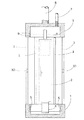
以下、本発明の実施例を図面に基づいて説明する。図1は地下水流測定装置の測定部の斜視図を示し、図6はその断面図を、図5は測定装置のブロック構成図を示している。1は測定ケースであり、図6に示すように、ボーリング孔等に挿入するための挿入用管8の下端に取付けられ、ボーリング孔等に挿入される。
【0017】
測定ケース1は、カップ状の容器を上部と下部に配設し、その上下カップ状容器の間を、多数の格子枠3で連結して構成され、格子枠3の部分が地下水の流通可能な流通部となる。測定ケース1の上部には、ケース内部に空気を入れるための空気管7が接続される。
【0018】
2は測定ケース1内に配設された絶縁体のフロートであり、例えばポリアセタール樹脂等により円柱状に形成され、内部に図示しない密閉された空気室を設けることにより、図6のように、測定ケース1内の水中で、立てた状態で浮遊する。また、その下部には、フロートセンタリング用及び高流速測定用の導体4が固定される。導体4としては、短いパイプ状或は円板状の銅やアルミニウム等、非磁性体の良導電体が良好である。
【0019】
さらに、導体4の周囲位置の測定ケース1の内側には、導体4に誘導電流を生じさせるための電磁誘導コイル5が巻装される。このコイル5の巻き径は例えば約30〜40mmとされ、センタリング用に約1〜10アンペアターンの電流、及び高流速測定用の微弱電流が得られるように巻装される。電磁誘導コイル5には、図5に示すように、電流制御回路18が接続され、電流制御回路18は後述のマイクロコンピュータ15により制御される。
【0020】
また、測定ケース1の中間部分に設けられた格子枠3の一部には、90度の間隔で4個の電極X1、X2、Y1、Y2が取付けられ、これら4個の電極は測定ケース1の横断面を平面とするX・Y平面上のX軸とY軸上に位置する。
【0021】
図5に示すように、各電極X1、X2、Y1、Y2はX・Y切換回路10に接続され、定電流回路11が、このX・Y切換回路10を介してX軸上に位置する一対の電極X1、X2とY軸上に位置する一対の電極Y1、Y2との間に、交互に一定の電流を供給するように接続される。
【0022】
X・Y切換回路10は、リレー回路、或はトランジスタのスイッチング回路等からなり、例えば10〜50Hz程度の周期で、電極X1、X2、Y1、Y2の電流供給側と電流検出側を各々切換え動作する。定電流回路11では、水の導電率の変化を補正するため、及び電極の電気分解による誤差をなくすために、例えば2kHzの矩形波を出力する交流電源が使用される。
【0023】
このX・Y切換回路10の出力側には、電極Y1からの電流を出力する回路に、電流電圧変換回路12aが接続され、電極Y2からの電流を出力する回路に、電流電圧変換回路12bが接続され、電極X1からの電流を出力する回路に、電流電圧変換回路12cが接続され、電極X2からの電流を出力する回路に、電流電圧変換回路12dが接続される。
【0024】
電流電圧変換回路12a,12b,12c,12dの出力側には、各々整流回路13a,13b,13c,13dが接続され、整流回路13aの出力側は、平滑回路を介して比較器14aの反転入力側に接続され、整流回路13bの出力側は、平滑回路を介して比較器14aの非反転入力側に接続される。
【0025】
また、整流回路13cの出力側は、平滑回路を介して比較器14bの反転入力側に接続され、整流回路13dの出力側は、平滑回路を介して比較器14bの非反転入力側に接続される。比較器14aは、電極Y1の電流と電極Y2の電流の差に対応した電圧を出力し、比較器14bは、電極X1の電流と電極X2の電流の差に対応した電圧を出力する。
【0026】
比較器14aと14bの出力側には、測定装置の主制御回路としてマイクロコンピュータ15が接続される。マイクロコンピュータ15は、CPU、固定メモリのROM、随時書込み読出し可能なRAM、及び入出力回路を備え、後述のフロートセンタリングの制御、電磁誘導コイル5の電流制御、フロートの移動開始時の電流値に基づく高流速の測定演算、及び各電極X1、X2、Y1、Y2間の電流値に基づく水流の流速と流向測定を行なう。水流の流速と流向の演算は、比較器14a,14bからの差電流Iy1、Iy2、Ix1,Ix2の各データを取り込み、所定の補正処理を行なった後、フロート2のX座標とY座標を算出する。X座標とY座標のデータはX・Yレコーダ16に出力されて、地下水流の方向として記録され、時間に対するフロートの移動距離を算出することにより流速が演算され、その演算結果は表示器17に数値表示される。
【0027】
フロートのセンタリング装置を用いて高流速の水流の流速を求めるために、予め実験から、水流の流速に対するフロートの移動開始電流が測定される。つまり、各種の流速の水流中でフロートを、センタリング用の誘導コイルに電流を流して測定ケース内の中央に位置させ、誘導コイルに流す電流値を徐々に低下させ、フロートが移動を開始した時点の電流値を測定する。そして、このような多数の流速に対応した電流値のデータが、予めテーブルデータ等としてROMに記憶される。
【0028】
次に、上記構成の地下水流測定装置を用いて、高流速(例えば数十m〜数百m/日)の地下水流を測定する場合を説明する。先ず、測定ケース1を予め穿設したボーリング孔に挿入し、測定ケース1を方位に対し正確に位置させて地下水中に入れる。
【0029】
地下水中における測定ケース1内には格子枠3の周囲から地下水が流入し、ケース内に充満する。そして、空気管7からケース1内に空気を供給することにより、ケース内上部に所定の量の空気層を形成し、ケース内の水位を図6のように所定位置とする。このときのケース内の水位はケース内周面に設けた水位センサ9により検出される。
【0030】
次に、測定開始と共に、マイクロコンピュータ15は、図7のステップ100を実行し、電流制御回路18を制御して、フロートセンタリング用の電流(例えば約1mA程度)を電磁誘導コイル5に供給する。すると、電磁誘導コイル5の周囲に磁界が発生し、このとき、電磁誘導コイル5の内側に位置するフロート2の導体4には、その磁界によって生じる磁束の変化を打ち消す方向に誘導電流(うず電流)が発生する。また、この誘導電流と磁界の関係から、この導体には、フレミング左手の法則により、電磁誘導コイル5の中央に向う力(電磁力)が発生する。
【0031】
このため、フロート2つまり導体4が測定ケース1つまり電磁誘導コイル5の中央に位置する場合、全ての方向から中央に向う均等な力を受け、フロート2は測定ケース1の中央位置に保持される。一方、フロート2が測定ケース1内の何れかの側に偏位して位置する場合、導体4が電磁誘導コイル5の一部に近づくことになる。この場合、導体4がその部分から受ける磁束密度は大きくなり、導体4に生じる誘導電流が増加し、導体4に生じる力(中央方向の力)もその部分で増大する。このため、その増大した力により、導体4つまりフロート2は、偏位位置から中央に向う力を受け、水流に抗して測定ケース1の中央に戻され、センタリングされる。
【0032】
次に、マイクロコンピュータ15は、ステップ110で、電磁誘導コイル5に供給しているセンタリング用の電流値を、電流制御回路18を制御することにより、徐々に減少制御し、次のステップ120で、フロート2が中央位置から水流により移動を開始したか否かを判定する。そして、ステップ110と120を繰り返し実行し、水流による力がセンタリングの電磁力(中央位置に保持する力)に勝った時、フロート2が中央位置より移動を開始するから、その時点で、次のステップ130に進み、その電流値を記憶する。
【0033】
フロート2がそのセンタリング位置から離れる際の位置の検出は、以下のように各電極X1、X2、Y1、Y2間の電圧値を測定して行なわれる。
【0034】
即ち、先ず、定電流回路11から各電極X1、X2、Y1、Y2に交流の矩形電流が供給される。定電流回路11からの電流は、図3、図4に示すように、電極X1、X2と電極Y1、Y2に交互に供給され、そのときの電極Y1、Y2と電極X1、X2から得られる電流が各々の回路に接続された電流電圧変換回路12a,12b,12c,12dに送られる。
【0035】
電流電圧変換回路12a,12b,12c,12dにより電流信号は電圧信号に変換され、それらの電圧信号が整流回路13a,13b,13c,13dで直流電圧に変換される。そして、電極Y1の電流Iy1に対応した電圧信号は比較器14aの反転入力に、電極Y2の電流Iy2に対応した電圧信号は比較器14aの非反転入力に入力される。また、電極X1の電流Ix1に対応した電圧信号は比較器14bの反転入力に、電極X2の電流Ix2に対応した電圧信号は比較器14bの非反転入力に入力される。そして、比較器14aからは電流Iy1,Iy2の差に対応した差電圧が出力され、比較器14bからは電流Ix1,Ix2の差に対応した差電圧が出力される。
【0036】
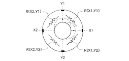
例えば、図2に示すように、フロート2が電極Y1方向に移動した場合、電極X1、X2よりみた電極Y1の電気抵抗R1は、フロート2により電流が遮られるため、増大し、逆に、電極X1、X2よりみた電極Y2の電気抵抗R2は、フロート2の影響が減少するため、減少する。同様に、フロート2が電極X1方向に移動した場合、電極Y1、Y2よりみた電極X1の電気抵抗R3は、フロート2により電流が遮られるため、増大し、逆に、電極Y1、Y2よりみた電極X2の電気抵抗R4は、フロート2の影響が減少するため、減少する。
【0037】
ここで、抵抗R1等は、合成抵抗であるから、1/R1=1/{R(X1、Y1)}+1/{R(X2、Y1)}となり、抵抗R2は、1/R2=1/{R(X2、Y2)}+1/{R(X1、Y2)}となる。また、抵抗R3は、1/R3=1/{R(X1、Y1)}+1/{R(X1、Y2)}となり、抵抗R4は、1/R4=1/{R(X2、Y2)}+1/{R(X2、Y1)}となる。
【0038】
したがって、図3に示すように、電源を電極X1、X2と電極Y1、Y2との間に接続して電流を供給し、電極Y1に流れる電流Iy1と電極Y2に流れる電流Iy2を測定し、電流Iy1とIy2の差を求め、フロートのY軸方向の移動を測定する。同様に、図4に示す如く、電源を電極X1、X2と電極Y1、Y2との間に接続して電流を供給し、電極X1に流れる電流Ix1と電極X2に流れる電流Ix2を測定し、電流Ix1とIx2の差を求め、フロートのX軸方向の移動を測定する。
【0039】
次に、マイクロコンピュータ15は、ステップ140において、上記ステップ130でフロート2が移動開始した時点の電流値に基づき、つまり、ROMに予め記憶された電流値に対する流速のデータテーブルを検索することにより、その電流値に対応した流速を算出する。算出された流速データは、メモリ等に書き込まれ、表示器17に表示される。
【0040】
このように、フロート2をセンタリングした状態で、電磁誘導コイル5の電流を徐々に低下させ、電磁力を徐々に下げていき、フロート2が移動を開始する時の電流値を求め、この電流値に基づき、水流の流速を測定するから、例えば流速が数十m〜数百m/日と非常に速い場合であっても、フロート2の移動範囲が約5mmと狭い範囲の測定装置で、正確に流速を測定することができる。
【0041】
次に、ステップ150で、マイクロコンピュータ15は電流制御回路18を制御して、電磁誘導コイル5への供給電流を遮断する。これにより、電磁誘導コイル5による導体4(フロート2)への電磁力は消失し、フロート2は自由に移動可能な状態となるから、以後、水流によって流されることになる。
【0042】
そして、次のステップ160にて、フロート2の移動方向から水流の流向を測定する。即ち、マイクロコンピュータ15は、上記同様に、電極X1、X2と電極Y1、Y2との間に定電流回路11を接続して電流を供給し、電極Y1に流れる電流Iy1と電極Y2に流れる電流Iy2を測定し、電流Iy1とIy2の差を求めて、フロートのY軸方向の移動を測定する。同様に、電極X1、X2と電極Y1、Y2との間に定電流回路11を接続して電流を供給し、電極X1に流れる電流Ix1と電極X2に流れる電流Ix2を測定し、電流Ix1とIx2の差を求めて、フロートのX軸方向の移動を測定する。このようにして求めたX座標とY座標のデータは、所定時間毎にX・Yレコーダ16に出力され、地下水流の方向がX・Y座標上に記録され、水流の流向が求められる。
【0043】
一方、流速が1日当り約9m〜0.9m/日の比較的遅い流速の地下水流を測定する場合には、電磁誘導コイル5に交流電流を供給してフロート2をセンタリングした後、電磁誘導コイル5への電流供給を遮断し、その後、上記ステップ160の処理と同様に、電極Y1に流れる電流Iy1と電極Y2に流れる電流Iy2を測定し、電流Iy1とIy2の差を求めて、フロートのY軸方向の移動を測定し、同様に、電極X1に流れる電流Ix1と電極X2に流れる電流Ix2を測定し、電流Ix1とIx2の差を求めて、フロートのX軸方向の移動を測定して、移動する時間と距離から、流速が算出される。
【0044】
なお、上記実施例では、フロート2をセンタリングした状態で、電磁誘導コイルの電流を徐々に低下させ、フロート2が移動を開始する時の電流値を求め、この電流値に基づき、水流の流速を測定したが、フロート2をセンタリングした状態で、電磁誘導コイル5に供給する電流を、一定の微弱電流まで減少させ、フロート2にセンター方向の電磁力を生じさせたまま、この電磁力により負荷を与えられたフロート2が、水流により移動する際の移動距離と電流値から、高流速水流の流速を求めることもできる。
【0045】
【発明の効果】
以上説明したように、本発明の地下水流測定装置によれば、フロートをセンタリングするための電磁誘導コイルに電流を供給・制御する電流制御手段により、フロートに水流の向きと相反する電磁力を生じさせ、その電流値に基づき地下水流の流速を算出するから、フロートが移動する際の速度を測定する代わりに、フロートが受ける水流の力に対応したセンタリングの電磁力つまり電磁誘導コイルに流す電流値に基づき流速を算出するので、流速が比較的速く、狭いフロートの移動範囲で正確な流速が測定できない場合であっても、水流の流速を正確に算出することができる。
【図面の簡単な説明】
【図1】本発明の一実施形態を示す地下水流測定装置の斜視図である。
【図2】測定ケース内の電極と電気抵抗の基本的関係を示す説明図である。
【図3】電極Y1とY2からの電流検出の説明図である。
【図4】電極X1とX2からの電流検出の説明図である。
【図5】地下水流測定装置のブロック構成図である。
【図6】測定ケース1の縦断面図である。
【図7】流速・流向測定の動作を示すフローチャートである。
【符号の説明】
1−測定ケース、
2−フロート、
3−格子枠、
4−導体、
5−電磁誘導コイル、
7−空気管、
15−マイクロコンピュータ
18−電流制御回路
X1、X2、Y1、Y2−電極。[0001]
BACKGROUND OF THE INVENTION
The present invention relates to a float-type groundwater flow measurement device that measures the flow velocity and flow direction of groundwater based on the movement speed and direction of the float, and more particularly to a groundwater flow measurement device suitable for measurement of a groundwater flow with a relatively high flow velocity.
[0002]
[Prior art]
Conventionally, as a single-hole type groundwater flow measurement method, a tracer method in which a tracer such as a chemical or dye is introduced into a measurement case and the flow direction or position of the tracer is measured to measure the flow velocity or flow direction of the water flow, or A camera method or the like is known in which a video camera is inserted into a measurement case, a floating substance is allowed to flow into the measurement case, and its movement is measured.
[0003]
[Problems to be solved by the invention]
However, the camera method using a video camera increases the size of the device and illuminates the front of the camera with a light so that the water temperature partially rises due to the light, and convection occurs, resulting in accurate groundwater flow. There was a problem that made it difficult to measure movement.
[0004]
Tracer methods are currently widely implemented and can measure groundwater flow trends with considerable accuracy, but when the water flow is very slow and the water can move freely, the tracer is injected into the water. As a result, there has been a problem that it is difficult to measure the groundwater flow with high accuracy due to the unstable movement of water and the diffusion phenomenon of the injected liquid.
[0005]
In addition, the method of injecting a tracer requires that the measurement be performed once after injecting the tracer and then the measurement case be pulled up from the borehole and refilled with the tracer. There was a problem that could not be done.
[0006]
Therefore, conventionally, in a state where the measurement case is put in water and an air layer is formed on the upper part, the float of the insulator is floated at the center position of the measurement case, and four pieces are spaced at intervals of 90 degrees on the inner peripheral wall of the measurement case. Based on the change in electrical resistance between adjacent electrodes that are arranged according to the position of the float in the measurement case, the position of the float is measured in time, and the direction and speed of the float that is moved by the groundwater flow, Devices for measuring groundwater flow direction and velocity have been developed.
[0007]
This float-type groundwater flow measuring device is usually formed with a float movement range of about 5 mm in the measurement case, and the float position is determined based on the change in electrical resistance between adjacent electrodes that changes according to the float position. Is measured in a timely manner, and the direction and velocity of the float moved by the groundwater flow are measured as the direction and velocity of the groundwater flow. In such a groundwater flow measuring device, when measuring a groundwater flow having a relatively low flow rate of about 9 m to 0.9 m / day per day, the flow rate can be accurately measured without any problem. If the flow rate is very fast, for example, several tens of meters to several hundreds of meters / day in the vicinity of the measurement or in the vicinity of the groundwater pumping, there is a problem that the error of the flow rate measurement value becomes very large.
[0008]
That is, the bore diameter of a well for measuring groundwater flow is usually 66 mm to 116 mm, but a pipe is inserted as an observation well to protect the borehole wall, and a cylindrical measuring device is inserted into the observation well. The range within which the float can move is about 10 mm from the center, and the range of float movement that can be used for flow velocity measurement is limited to about 5 mm, excluding unstable areas near the center or the periphery. Will be. For this reason, when the flow rate is very fast, for example, several tens of meters to several hundreds m / day, there is a problem that the error of the flow rate measurement value becomes very large.
[0009]
By the way, if the measuring device is increased in size, it is naturally possible to increase the range of movement of the float, but in that case, it is necessary to enlarge the boring hole and a different measuring device is required depending on the flow velocity. From the above, it is expected that the workability and economic efficiency will be deteriorated.
[0010]
This invention is made | formed in view of said point, and an object of this invention is to provide the groundwater flow measuring apparatus which can measure a groundwater flow with a comparatively quick flow velocity stably and correctly.
[0011]
[Means for Solving the Problems]
In order to achieve the above object, a groundwater flow measurement device according to the present invention includes a measurement case having a circulation port through which groundwater can be circulated, a float of an insulator disposed in the measurement case, and air supplied into the measurement case. An air supply means, two pairs of electrodes disposed on the X and Y planes on the inner circumferential wall of the measurement case, the X and Y planes having the cross section of the measurement case as a plane, and the X axis A constant current circuit for supplying a constant current between the pair of electrodes X1 and X2 positioned on the upper side and the pair of electrodes Y1 and Y2 positioned on the Y-axis, and each electrode when supplying current from the constant current circuit While detecting the flowing current, the difference between the current value of the pair of electrodes X1, X2 located on the X axis and the difference of the current value of the pair of electrodes Y1, Y2 located on the Y axis are calculated, and the float X / Y coordinate signal generation to generate X coordinate signal and Y coordinate signal indicating the position of And a processing means for calculating the movement direction and speed of the float based on the X coordinate signal and the Y coordinate signal from the X / Y coordinate signal generation means, a conductor attached to the float, and a position around the conductor. An electromagnetic induction coil that is arranged inside the measurement case and generates an induced current in the conductor, a current control means that supplies and controls an alternating current to the electromagnetic induction coil, and an electromagnetic that contradicts the direction of water flow to the float by the current control means A flow rate calculating means for generating a force and calculating a flow rate of the groundwater flow based on the value of the alternating current, and the current control means supplies the current to the electromagnetic induction coil and causes the current to flow while the float is centered. The flow rate calculation means calculates the flow rate of the groundwater flow based on the current value at the start of the movement of the float .
[0012]
Here, the flow velocity calculation means is based on the current value and the movement speed of the float when the current control means supplies current to the electromagnetic induction coil to cause the float to generate electromagnetic force opposite to the direction of water flow and to center the float. The groundwater flow velocity can be calculated.
[0013]
[Action]
The groundwater flow measuring device having the above configuration is configured to supply an alternating current to the electromagnetic induction coil in a state where the float is suspended in the measurement case at the time of measurement, and to the float conductor located inside the electromagnetic induction coil at the center. The center of the float is performed by generating an electromagnetic force toward In the centered state, the current control means generates an electromagnetic force in a direction opposite to the direction of the water flow in the float, but thereafter the current of the electromagnetic induction coil is gradually reduced. The flow velocity calculation means takes in a current value at the time when the float starts moving due to a decrease in electromagnetic force, and calculates the flow velocity of the groundwater flow based on this current value.
[0014]
Thus, instead of measuring the speed at which the float moves due to the water flow, the flow velocity is calculated based on the centering electromagnetic force corresponding to the force of the water flow received by the float, that is, the current value flowing through the electromagnetic induction coil. Even when the accurate flow velocity cannot be measured in a relatively fast and narrow float movement range, the flow velocity of the water flow can be accurately calculated from the electromagnetic force of the centering, that is, the current value flowing through the electromagnetic induction coil.
[0015]
On the other hand, the flow direction of the water flow is determined by measuring the flow velocity and then cutting off the current of the electromagnetic induction coil to eliminate the electromagnetic force. And using arithmetic processing means. The X / Y coordinate signal generating means detects the current flowing through each electrode when the current is supplied from the constant current circuit, and the current value difference between the pair of electrodes X1 and X2 located on the X axis and the position on the Y axis. The difference between the current values of the pair of electrodes Y1 and Y2 is calculated to generate an X coordinate signal and a Y coordinate signal indicating the position of the float. The arithmetic processing means calculates the movement direction of the float based on the X coordinate signal and the Y coordinate signal from the X / Y coordinate signal generating means.
[0016]
DETAILED DESCRIPTION OF THE INVENTION
Embodiments of the present invention will be described below with reference to the drawings. FIG. 1 is a perspective view of a measurement unit of a groundwater flow measurement device, FIG. 6 is a sectional view thereof, and FIG. 5 is a block diagram of the measurement device.
[0017]
The
[0018]
[0019]
Furthermore, an
[0020]
In addition, four electrodes X1, X2, Y1, and Y2 are attached to a part of the
[0021]
As shown in FIG. 5, each of the electrodes X1, X2, Y1, and Y2 is connected to an X /
[0022]
The X /
[0023]
On the output side of the
[0024]
[0025]
The output side of the
[0026]
A
[0027]
In order to obtain the flow velocity of the high flow rate water flow using the float centering device, the movement start current of the float with respect to the flow velocity of the water flow is measured in advance from an experiment. In other words, when the float starts moving in the water flow at various flow speeds, the current flows through the centering induction coil to be positioned at the center of the measurement case, and the current value flowing through the induction coil is gradually reduced. Measure the current value. Then, current value data corresponding to such a large number of flow rates is stored in advance in the ROM as table data or the like.
[0028]
Next, a case where a groundwater flow having a high flow velocity (for example, several tens of meters to several hundreds of meters / day) is measured using the groundwater flow measuring device having the above configuration will be described. First, the
[0029]
Groundwater flows into the
[0030]
Next, with the start of measurement, the
[0031]
For this reason, when the
[0032]
Next, in
[0033]
Detection of the position when the
[0034]
That is, first, an alternating rectangular current is supplied from the constant
[0035]
Current signals are converted into voltage signals by the current-
[0036]
For example, as shown in FIG. 2, when the
[0037]
Here, since the resistor R1 and the like are combined resistors, 1 / R1 = 1 / {R (X1, Y1)} + 1 / {R (X2, Y1)}, and the resistor R2 has 1 / R2 = 1 / {R (X2, Y2)} + 1 / {R (X1, Y2)}. The resistance R3 is 1 / R3 = 1 / {R (X1, Y1)} + 1 / {R (X1, Y2)}, and the resistance R4 is 1 / R4 = 1 / {R (X2, Y2)}. + 1 / {R (X2, Y1)}.
[0038]
Therefore, as shown in FIG. 3, a power source is connected between the electrodes X1 and X2 and the electrodes Y1 and Y2, the current is supplied, the current Iy1 flowing through the electrode Y1 and the current Iy2 flowing through the electrode Y2 are measured, The difference between Iy1 and Iy2 is obtained, and the movement of the float in the Y-axis direction is measured. Similarly, as shown in FIG. 4, a power source is connected between the electrodes X1 and X2 and the electrodes Y1 and Y2, the current is supplied, the current Ix1 flowing through the electrode X1 and the current Ix2 flowing through the electrode X2 are measured, The difference between Ix1 and Ix2 is obtained, and the movement of the float in the X-axis direction is measured.
[0039]
Next, in
[0040]
In this way, with the
[0041]
Next, in
[0042]
Then, in the
[0043]
On the other hand, when measuring a groundwater flow having a relatively slow flow rate of about 9 m to 0.9 m / day per day, an AC current is supplied to the
[0044]
In the above embodiment, with the
[0045]
【The invention's effect】
As described above, according to the groundwater flow measuring device of the present invention, an electromagnetic force that contradicts the direction of the water flow is generated in the float by the current control means that supplies and controls the current to the electromagnetic induction coil for centering the float. Therefore, instead of measuring the speed when the float moves, the centering electromagnetic force corresponding to the force of the water flow received by the float, that is, the current value that flows through the electromagnetic induction coil is calculated based on the current value. Therefore, even when the flow rate is relatively fast and an accurate flow rate cannot be measured within a narrow float movement range, the flow rate of the water flow can be accurately calculated.
[Brief description of the drawings]
FIG. 1 is a perspective view of a groundwater flow measuring device showing an embodiment of the present invention.
FIG. 2 is an explanatory diagram showing a basic relationship between an electrode and electric resistance in a measurement case.
FIG. 3 is an explanatory diagram of current detection from electrodes Y1 and Y2.
FIG. 4 is an explanatory diagram of current detection from electrodes X1 and X2.
FIG. 5 is a block diagram of a groundwater flow measurement device.
6 is a longitudinal sectional view of a
FIG. 7 is a flowchart showing the flow velocity / flow direction measurement operation.
[Explanation of symbols]
1-measurement case,
2-float,
3- lattice frame,
4-conductor,
5- electromagnetic induction coil,
7-air tube,
15-microcomputer 18-current control circuit X1, X2, Y1, Y2-electrode.
Claims (2)
該測定ケース内に配置された絶縁体のフロートと、
該測定ケース内に空気を供給する空気供給手段と、
該測定ケースの内周壁に、該測定ケースの横断面を平面とするX・Y平面上のX軸とY軸上に位置して配設された2対の電極と、
X軸上に位置する一対の電極X1、X2とY軸上に位置する一対の電極Y1、Y2との間に、一定の電流を供給する定電流回路と、
該定電流回路からの電流供給時に各電極に流れる電流を検出すると共に、X軸上に位置する一対の電極X1、X2の電流値の差とY軸上に位置する一対の電極Y1、Y2の電流値の差とを演算して、該フロートの位置を示すX座標信号とY座標信号を発生するX・Y座標信号発生手段と、
X・Y座標信号発生手段からのX座標信号とY座標信号に基づき、フロートの移動方向と移動速度を演算する演算処理手段と、
該フロートに取付けられた導体と、
該導体の周囲位置の該測定ケースの内側に配設され、該導体に誘導電流を生じさせる電磁誘導コイルと、
該電磁誘導コイルに交流電流を供給し制御する電流制御手段と、
該電流制御手段により該フロートに水流の向きと相反する電磁力を生じさせ、該交流電流の値に基づき地下水流の流速を算出する流速算出手段と、
を備え、
前記電流制御手段は、前記電磁誘導コイルに電流を供給して前記フロートをセンタリングさせた状態で、該電流を徐々に低下させ、前記流速算出手段は、該フロートの移動開始時の該電流値に基づき、該地下水流の流速を算出することを特徴とする地下水流測定装置。A measurement case having a distribution port through which groundwater can be distributed;
An insulator float disposed in the measurement case;
Air supply means for supplying air into the measurement case;
Two pairs of electrodes disposed on the X and Y planes on the X and Y planes with the cross section of the measurement case as a plane on the inner peripheral wall of the measurement case;
A constant current circuit for supplying a constant current between the pair of electrodes X1 and X2 located on the X axis and the pair of electrodes Y1 and Y2 located on the Y axis;
While detecting the current flowing through each electrode when supplying current from the constant current circuit, the difference between the current value of the pair of electrodes X1 and X2 located on the X axis and the pair of electrodes Y1 and Y2 located on the Y axis X / Y coordinate signal generating means for calculating an X coordinate signal indicating a position of the float and a Y coordinate signal by calculating a difference between current values;
Arithmetic processing means for calculating the movement direction and speed of the float based on the X coordinate signal and the Y coordinate signal from the X / Y coordinate signal generating means;
A conductor attached to the float;
An electromagnetic induction coil that is disposed inside the measurement case at a position around the conductor and generates an induced current in the conductor;
Current control means for supplying and controlling an alternating current to the electromagnetic induction coil;
A flow rate calculating means for generating an electromagnetic force in the float opposite to the direction of the water flow by the current control means, and calculating a flow rate of the groundwater flow based on the value of the alternating current;
With
The current control means gradually reduces the current in a state where the float is centered by supplying current to the electromagnetic induction coil, and the flow velocity calculation means sets the current value at the start of movement of the float to the current value. A groundwater flow measuring device that calculates a flow velocity of the groundwater flow based on the groundwater flow.
該測定ケース内に配置された絶縁体のフロートと、
該測定ケース内に空気を供給する空気供給手段と、
該測定ケースの内周壁に、該測定ケースの横断面を平面とするX・Y平面上のX軸とY軸上に位置して配設された2対の電極と、
X軸上に位置する一対の電極X1、X2とY軸上に位置する一対の電極Y1、Y2との間に、一定の電流を供給する定電流回路と、
該定電流回路からの電流供給時に各電極に流れる電流を検出すると共に、X軸上に位置する一対の電極X1、X2の電流値の差とY軸上に位置する一対の電極Y1、Y2の電流値の差とを演算して、該フロートの位置を示すX座標信号とY座標信号を発生するX・Y座標信号発生手段と、
X・Y座標信号発生手段からのX座標信号とY座標信号に基づき、フロートの移動方向と移動速度を演算する演算処理手段と、
該フロートに取付けられた導体と、
該導体の周囲位置の該測定ケースの内側に配設され、該導体に誘導電流を生じさせる電磁誘導コイルと、
該電磁誘導コイルに交流電流を供給し制御する電流制御手段と、
該電流制御手段により該フロートに水流の向きと相反する電磁力を生じさせ、該交流電流の値に基づき地下水流の流速を算出する流速算出手段と、
を備え、
前記流速算出手段は、前記電流制御手段が前記電磁誘導コイルに電流を供給して前記フロートに水流の向きに相反する電磁力を生じさせて該フロートをセンタリングさせる際の電流値と該フロートの移動速度に基づき、地下水流の流速を算出することを特徴とする地下水流測定装置。 A measurement case having a distribution port through which groundwater can be distributed;
An insulator float disposed in the measurement case;
Air supply means for supplying air into the measurement case;
Two pairs of electrodes disposed on the X and Y planes on the X and Y planes with the cross section of the measurement case as a plane on the inner peripheral wall of the measurement case;
A constant current circuit for supplying a constant current between the pair of electrodes X1 and X2 located on the X axis and the pair of electrodes Y1 and Y2 located on the Y axis;
While detecting the current flowing through each electrode when supplying current from the constant current circuit, the difference between the current value of the pair of electrodes X1 and X2 located on the X axis and the pair of electrodes Y1 and Y2 located on the Y axis X / Y coordinate signal generating means for calculating an X coordinate signal indicating a position of the float and a Y coordinate signal by calculating a difference between current values;
Arithmetic processing means for calculating the movement direction and speed of the float based on the X coordinate signal and the Y coordinate signal from the X / Y coordinate signal generating means;
A conductor attached to the float;
An electromagnetic induction coil that is disposed inside the measurement case at a position around the conductor and generates an induced current in the conductor;
Current control means for supplying and controlling an alternating current to the electromagnetic induction coil;
A flow rate calculating means for generating an electromagnetic force in the float opposite to the direction of the water flow by the current control means, and calculating a flow rate of the groundwater flow based on the value of the alternating current;
With
The flow velocity calculating means supplies the current to the electromagnetic induction coil by the current control means to generate an electromagnetic force opposite to the direction of water flow in the float, and the current value and the movement of the float when the float is centered. A groundwater flow measurement device that calculates the flow velocity of a groundwater flow based on velocity .
Priority Applications (1)
| Application Number | Priority Date | Filing Date | Title |
|---|---|---|---|
| JP2000004475A JP4163358B2 (en) | 2000-01-13 | 2000-01-13 | Groundwater flow measurement device |
Applications Claiming Priority (1)
| Application Number | Priority Date | Filing Date | Title |
|---|---|---|---|
| JP2000004475A JP4163358B2 (en) | 2000-01-13 | 2000-01-13 | Groundwater flow measurement device |
Publications (2)
| Publication Number | Publication Date |
|---|---|
| JP2001194467A JP2001194467A (en) | 2001-07-19 |
| JP4163358B2 true JP4163358B2 (en) | 2008-10-08 |
Family
ID=18533263
Family Applications (1)
| Application Number | Title | Priority Date | Filing Date |
|---|---|---|---|
| JP2000004475A Expired - Lifetime JP4163358B2 (en) | 2000-01-13 | 2000-01-13 | Groundwater flow measurement device |
Country Status (1)
| Country | Link |
|---|---|
| JP (1) | JP4163358B2 (en) |
Families Citing this family (1)
| Publication number | Priority date | Publication date | Assignee | Title |
|---|---|---|---|---|
| CA2662742C (en) * | 2006-09-12 | 2015-08-04 | Posiva Oy | Measuring head and measuring method |
-
2000
- 2000-01-13 JP JP2000004475A patent/JP4163358B2/en not_active Expired - Lifetime
Also Published As
| Publication number | Publication date |
|---|---|
| JP2001194467A (en) | 2001-07-19 |
Similar Documents
| Publication | Publication Date | Title |
|---|---|---|
| CN100451563C (en) | Method for testing a magnetic inductive flow meter | |
| JP2004012308A (en) | Position measuring device utilizing coil, float type flowmeter, and method of measuring position | |
| CN103412009B (en) | A kind of apparatus and method measuring fluid conductivity | |
| US20180045545A1 (en) | Magneto-inductive flow measuring device with reduced electrical current draw | |
| CN106932036A (en) | For the method that the flow measuring device by Magnetic Induction carries out flow measurement | |
| US20230213367A1 (en) | Method of operating a magnetically-inductive flowmeter | |
| CN106574858B (en) | Magnetic-inductive flow measuring device with a plurality of measuring electrode pairs and different measuring tube cross sections | |
| CN115698647A (en) | Magnetic-inductive flow measuring device | |
| JP4163358B2 (en) | Groundwater flow measurement device | |
| JP3880729B2 (en) | Groundwater flow measurement device | |
| JP3002807B2 (en) | Float centering device for groundwater flow measurement device | |
| KR100738321B1 (en) | Apparatus for measuring the magnetic moment | |
| JPH05231892A (en) | Flow-rate measuring apparatus | |
| JP3013218B2 (en) | Groundwater flow measurement method and device | |
| CN104995489A (en) | Method for operating a magnetic-inductive flow meter | |
| RU2716601C2 (en) | Electromagnetic method of measuring flow rate of liquid metal | |
| JP2018080966A (en) | Electromagnetic flowmeter | |
| JP3551602B2 (en) | Drilling hole water leak position measuring method and measuring device | |
| CN117642608A (en) | Magnetic induction flow measuring device | |
| EP3680626A1 (en) | Magnetic flowmeter with media conductivity measurement | |
| JP2004028998A (en) | Magnetic induction flow measurement method | |
| Malcolm | An investigation of the stability of a magnetohydrodynamic shear layer | |
| JPH0814972A (en) | Electromagnetic flowmeter | |
| JPH0835867A (en) | Electromagnetic flowmeter | |
| JPH10221135A (en) | Electromagnetic flowmeter |
Legal Events
| Date | Code | Title | Description |
|---|---|---|---|
| A621 | Written request for application examination |
Free format text: JAPANESE INTERMEDIATE CODE: A621 Effective date: 20061113 |
|
| A977 | Report on retrieval |
Free format text: JAPANESE INTERMEDIATE CODE: A971007 Effective date: 20080409 |
|
| A131 | Notification of reasons for refusal |
Free format text: JAPANESE INTERMEDIATE CODE: A131 Effective date: 20080422 |
|
| A521 | Written amendment |
Free format text: JAPANESE INTERMEDIATE CODE: A523 Effective date: 20080530 |
|
| TRDD | Decision of grant or rejection written | ||
| A01 | Written decision to grant a patent or to grant a registration (utility model) |
Free format text: JAPANESE INTERMEDIATE CODE: A01 Effective date: 20080624 |
|
| A01 | Written decision to grant a patent or to grant a registration (utility model) |
Free format text: JAPANESE INTERMEDIATE CODE: A01 |
|
| A61 | First payment of annual fees (during grant procedure) |
Free format text: JAPANESE INTERMEDIATE CODE: A61 Effective date: 20080724 |
|
| FPAY | Renewal fee payment (event date is renewal date of database) |
Free format text: PAYMENT UNTIL: 20110801 Year of fee payment: 3 |
|
| R150 | Certificate of patent or registration of utility model |
Ref document number: 4163358 Country of ref document: JP Free format text: JAPANESE INTERMEDIATE CODE: R150 Free format text: JAPANESE INTERMEDIATE CODE: R150 |
|
| FPAY | Renewal fee payment (event date is renewal date of database) |
Free format text: PAYMENT UNTIL: 20110801 Year of fee payment: 3 |
|
| FPAY | Renewal fee payment (event date is renewal date of database) |
Free format text: PAYMENT UNTIL: 20140801 Year of fee payment: 6 |
|
| R250 | Receipt of annual fees |
Free format text: JAPANESE INTERMEDIATE CODE: R250 |
|
| R250 | Receipt of annual fees |
Free format text: JAPANESE INTERMEDIATE CODE: R250 |
|
| R250 | Receipt of annual fees |
Free format text: JAPANESE INTERMEDIATE CODE: R250 |
|
| R250 | Receipt of annual fees |
Free format text: JAPANESE INTERMEDIATE CODE: R250 |
|
| EXPY | Cancellation because of completion of term |