JP4159748B2 - Fracture fixation system - Google Patents
Fracture fixation system Download PDFInfo
- Publication number
- JP4159748B2 JP4159748B2 JP2000569709A JP2000569709A JP4159748B2 JP 4159748 B2 JP4159748 B2 JP 4159748B2 JP 2000569709 A JP2000569709 A JP 2000569709A JP 2000569709 A JP2000569709 A JP 2000569709A JP 4159748 B2 JP4159748 B2 JP 4159748B2
- Authority
- JP
- Japan
- Prior art keywords
- pin
- shaft
- tip
- bone
- fixation system
- Prior art date
- Legal status (The legal status is an assumption and is not a legal conclusion. Google has not performed a legal analysis and makes no representation as to the accuracy of the status listed.)
- Expired - Fee Related
Links
- 0 **C(C(*=C)O)C1=C=N1 Chemical compound **C(C(*=C)O)C1=C=N1 0.000 description 1
Images


Classifications
-
- A—HUMAN NECESSITIES
- A61—MEDICAL OR VETERINARY SCIENCE; HYGIENE
- A61B—DIAGNOSIS; SURGERY; IDENTIFICATION
- A61B17/00—Surgical instruments, devices or methods, e.g. tourniquets
- A61B17/56—Surgical instruments or methods for treatment of bones or joints; Devices specially adapted therefor
- A61B17/58—Surgical instruments or methods for treatment of bones or joints; Devices specially adapted therefor for osteosynthesis, e.g. bone plates, screws, setting implements or the like
- A61B17/68—Internal fixation devices, including fasteners and spinal fixators, even if a part thereof projects from the skin
- A61B17/72—Intramedullary pins, nails or other devices
- A61B17/7291—Intramedullary pins, nails or other devices for small bones, e.g. in the foot, ankle, hand or wrist
-
- A—HUMAN NECESSITIES
- A61—MEDICAL OR VETERINARY SCIENCE; HYGIENE
- A61B—DIAGNOSIS; SURGERY; IDENTIFICATION
- A61B17/00—Surgical instruments, devices or methods, e.g. tourniquets
- A61B17/16—Bone cutting, breaking or removal means other than saws, e.g. Osteoclasts; Drills or chisels for bones; Trepans
- A61B17/1662—Bone cutting, breaking or removal means other than saws, e.g. Osteoclasts; Drills or chisels for bones; Trepans for particular parts of the body
- A61B17/1682—Bone cutting, breaking or removal means other than saws, e.g. Osteoclasts; Drills or chisels for bones; Trepans for particular parts of the body for the foot or ankle
-
- A—HUMAN NECESSITIES
- A61—MEDICAL OR VETERINARY SCIENCE; HYGIENE
- A61B—DIAGNOSIS; SURGERY; IDENTIFICATION
- A61B17/00—Surgical instruments, devices or methods, e.g. tourniquets
- A61B17/16—Bone cutting, breaking or removal means other than saws, e.g. Osteoclasts; Drills or chisels for bones; Trepans
- A61B17/1662—Bone cutting, breaking or removal means other than saws, e.g. Osteoclasts; Drills or chisels for bones; Trepans for particular parts of the body
- A61B17/1686—Bone cutting, breaking or removal means other than saws, e.g. Osteoclasts; Drills or chisels for bones; Trepans for particular parts of the body for the hand or wrist
-
- A—HUMAN NECESSITIES
- A61—MEDICAL OR VETERINARY SCIENCE; HYGIENE
- A61B—DIAGNOSIS; SURGERY; IDENTIFICATION
- A61B17/00—Surgical instruments, devices or methods, e.g. tourniquets
- A61B17/56—Surgical instruments or methods for treatment of bones or joints; Devices specially adapted therefor
- A61B17/58—Surgical instruments or methods for treatment of bones or joints; Devices specially adapted therefor for osteosynthesis, e.g. bone plates, screws, setting implements or the like
- A61B17/68—Internal fixation devices, including fasteners and spinal fixators, even if a part thereof projects from the skin
- A61B17/72—Intramedullary pins, nails or other devices
- A61B17/7208—Flexible pins, e.g. ENDER pins
-
- A—HUMAN NECESSITIES
- A61—MEDICAL OR VETERINARY SCIENCE; HYGIENE
- A61B—DIAGNOSIS; SURGERY; IDENTIFICATION
- A61B17/00—Surgical instruments, devices or methods, e.g. tourniquets
- A61B17/56—Surgical instruments or methods for treatment of bones or joints; Devices specially adapted therefor
- A61B17/58—Surgical instruments or methods for treatment of bones or joints; Devices specially adapted therefor for osteosynthesis, e.g. bone plates, screws, setting implements or the like
- A61B17/88—Osteosynthesis instruments; Methods or means for implanting or extracting internal or external fixation devices
- A61B17/92—Impactors or extractors, e.g. for removing intramedullary devices
- A61B17/921—Impactors or extractors, e.g. for removing intramedullary devices for intramedullary devices
Landscapes
- Health & Medical Sciences (AREA)
- Surgery (AREA)
- Life Sciences & Earth Sciences (AREA)
- Orthopedic Medicine & Surgery (AREA)
- Medical Informatics (AREA)
- General Health & Medical Sciences (AREA)
- Veterinary Medicine (AREA)
- Engineering & Computer Science (AREA)
- Biomedical Technology (AREA)
- Heart & Thoracic Surgery (AREA)
- Public Health (AREA)
- Molecular Biology (AREA)
- Animal Behavior & Ethology (AREA)
- Nuclear Medicine, Radiotherapy & Molecular Imaging (AREA)
- Dentistry (AREA)
- Oral & Maxillofacial Surgery (AREA)
- Neurology (AREA)
- Surgical Instruments (AREA)
- Prostheses (AREA)
- Laying Of Electric Cables Or Lines Outside (AREA)
- Joints Allowing Movement (AREA)
- Flanged Joints, Insulating Joints, And Other Joints (AREA)
Abstract
Description
【0001】
【発明の属する技術分野】
本発明は、広くは、骨折固定用のシステムに関する。更に詳細には、本発明は比較的小さな骨の骨折部を固定するための改良された方法及びこれと関連したシステムに関する。
【0002】
【従来の技術】
中手骨の骨折は非常に一般的である。中手骨を骨折部のいずれかの側で定着することは、適切な治癒にとって必須である。しかしながら、骨折の位置によっては、理想的に定着する上で幾つかの困難がある。
【0003】
骨折部を定着する上で最も多く使用されている治療は、副木装着及び鋳造である。しかしながら、中手骨の位置のため、こうした治療では、中手骨の骨折部が適切に修復される状態を維持することができない。損傷した骨に手術治療によって取り付けたプレート、固定ねじ、及び固定ピンを使用する技術によって強く固定することができる。このような種類の骨折部修復装置は、比較的大きな骨折で、例えば尺骨、脛骨、又は大腿骨の骨折で一般的に使用されているけれども、このような手術治療は、一般的にはひどく大きな切開部を残し、骨折部を露呈する。従って、このような技術は、多くの場合、比較的小さく壊れ易い中手骨については浸襲度が大き過ぎると判断される。
【0004】
浸襲度が小さい別の技術が使用されてきた。この技術では、中手骨の基端の皮膚に小さな切開部を形成し、この切開部を通してボーリング工具を挿入し、このボーリング工具を使用して中手骨に小さな穴を穿ち、ボーリング工具を取り出した後、医師が切開部を通してピンを骨の小さな見えないボア内に供給する。しかしながら皮膚を通してピンを送り出すのは、ピン及び骨に穿孔した小穴の相対的位置を医師に示すための手段がない手探りの手術(blind operation)である。このように、この技術は、手探りで送り出すことにより周囲組織に増悪する損傷をもたらす場合があるため、医師にとっても患者にとっても好ましくない。更に、埋め込んだピンは、回転に関して定着する必要がある骨折部を捩じりに関して固定しない。
【0005】
更に、中足骨の骨折及び指節骨の骨折に関して同様の問題点が存在する。
【0006】
【発明が解決しようとする課題】
従って、本発明の目的は、中手骨、中足骨、及び指節骨の骨折、及び同様の骨の骨折に対して安定した固定を可能にする骨折固定システムを提供することである。
【0007】
本発明の別の目的は、中手骨、中足骨、及び指節骨の骨折、及び同様の骨の骨折に対して内部経皮的固定を提供する骨折固定システムを提供することである。
本発明の更に別の目的は、中手骨、中足骨、及び指節骨の骨折、及び同様の骨の骨折に対して捩じり安定性を提供する骨折固定システムを提供することである。
【0008】
本発明の他の目的は、中手骨、中足骨、及び指節骨の骨折、及び同様の骨の骨折に対して大きさを調節できる固定システムを提供する骨折固定システムを提供することである。
【0009】
本発明の更に他の目的は、従来技術の手術治療と比較して浸襲度が比較的小さい骨折固定システムを提供することである。
以下に詳細に論じるこれらの目的に従って骨折固定システムが提供される。簡単のため、骨折固定システムを、全体として、中手骨を参照して説明するが、このシステムは中足骨、指節骨、及び同様の骨にも適用できる。
【0010】
【課題を解決するための手段】
本発明の一実施例によれば、システムは、固定ピン及び固定ピンを埋め込むための器具を含む。本発明の第1実施例によれば、器具は、主ハンドル及びこの主ハンドルに対して移動自在のピンハンドルを含む。主ハンドルは、基端、先端、及びハンドルの先端に開口部を持つ長さ方向スロットを含む。主ハンドルの先端にボーリングシャフト(ドリル)が連結される。ボーリングシャフトは、先端ボーリングチップ及び固定ピンを髄管内に案内するため、ボーリングチップと基端方向で隣接したチップガイドを含む。ピンガイドは、好ましくは、シャフトに設けられた溝である。ピンハンドルは、長さ方向スロット内で摺動自在に移動するような形状及び大きさになっており、フィンガグリップ及び固定ピンを内部に受け入れる先端ボアが設けられている。固定ピンは、好ましくは、実質的に直線状の基端部分及び中央部分、及び好ましくは尖っていないチップが設けられた先端部分を含む。先ず最初に、湾曲した先端部分がボーリングシャフトのピンガイド内に載止する。ピンハンドルを主ハンドルのスロット内で相対的に先端方向に移動させると、固定ピンの先端部分がピンガイドを通って及びこのガイドを越えて移動するということは理解されよう。
【0011】
使用にあたっては、器具の主ハンドルを操作し、患者の手の骨折した中手骨のベースにボーリングシャフトを皮下的に導入する。シャフトのチップを中手骨のベースに導入した後、これをその位置に残し、ピンハンドルを主ハンドルに対して先端方向に移動し、固定ピンの先端部分を骨に押し込む。ピンは、これによって、骨の髄管の自然の中空に進入する。次いで、主ハンドルをピンハンドルに対して基端方向に移動し、ボーリングシャフトを患者の手から取り出し、主ハンドルをピンハンドルと係合した状態から外す。次いで、ピンハンドルを更に移動し、ピンを、髄管を通って骨折部の両側に延び且つ骨折した骨の必要な定着を提供するまで、骨折した中手骨の髄管の自然の中空を通して押す。チップの先端が尖っていないため、中手骨の先端を穿刺することがない。最後に、ピンの基端を曲げ、切断し、好ましくは皮下に着座させる。
【0012】
骨折固定システムの器具の別の実施例によれば、器具は、先端にボーリングシャフトが連結されたシャフトハンドルを含む。ボーリングシャフトは、内部通路及び先端出口を有する。シャフトハンドルは、シャフトの内部通路と連通した通孔を含み、この通孔を通して固定ピンを受け入れることができる。ハンドルにより、シャフトを手作業で皮下的に挿入し回転させてボーリングシャフトのチップを中手骨に入れることができる。先端出口は、軸線方向に設けられているか或いは横方向に設けられている。随意であるが、突き錐部材を通孔及び内部通路内に設けてシャフトの先端出口まで延ばすことができる。これは、シャフトを中手骨に挿入し、次いで固定ピンをシャフトの内部通路及び先端出口を通して延ばすために取り出すために行われる。別の実施例によれば、ボーリングシャフトの通路には、基端横方向出口、及びシャフトの先端で横方向又は軸線方向のいずれかに延びる出口が設けられている。
【0013】
更に、別の態様では、固定ピンは、髄管に従って移動するように自己案内式になっているのがよい。ピンの基端部分及び中央部分は比較的直線状であり、十分に剛性である(骨に強制的に挿入できるけれども固定を提供する)。先端が中央部分に対して容易に曲がることができ且つ髄管に従って移動できるようにする縮径部分が先端と隣接して設けられている。好ましくは、ピンに見掛け上一定の直径を提供するため、コイルが縮径部分の周囲に設けられる。
【0014】
更に、固定ピンは、特に、指節骨に見られるような比較的小さな髄管で使用するように適合でき、即ち固定ピンは、先端直径が比較的小さいのがよい。このような固定ピンを、中手骨及び中足骨に適合した固定ピンに使用されているのと同じピンハンドルで使用できるようにするため、固定ピンは、均等な直径を持つ基端、直径が比較的小さい先端、及び基端と先端との間のテーパ部分又は段部分を含む。
【0015】
本発明の更に別の実施例によれば、固定システムは、複数の固定ピン及び骨折した骨の髄管内に少なくとも二つの固定ピンを順次埋め込むための器具を含む。上文中に説明したように、器具には、ピンハンドルに各々を別々に装着可能なピンが設けられている。これらのピンは、同じ直径であってもよいし、様々な直径のピンを含む組として提供されてもよい。個々のピンの各々は、骨の髄管よりも小さいが、一つ又はそれ以上の他のピンと組み合わせて埋め込んだ場合に、必要な固定を提供するため、髄管の内径とほぼ同じになる。各個々のピンを上文中に説明したように埋め込む。骨折部を安定させるため、少なくとも二つのピンを埋め込む。好ましくは、ピンを互いに連結することによってピンが相対的に回転しないようにするため、コレットがピンの基端上に設けられる。更に、コレットは、好ましくは、ピンの基端を骨に対して定着するため、骨に連結されるようになっている。このように、固定システムは、骨折部の捩じり安定性を提供する。
【0016】
本発明の追加の目的及び利点は、以下の詳細な説明を添付図面と関連して参照することにより、当業者には明らかになるであろう。
【0017】
【発明の実施の形態】
上述のように、本発明を中手骨の骨折に関して説明するが、本発明は、中足骨及び指節骨の骨折の固定にも適用される。次に図1乃至図4を参照すると、これらの図には、骨折した中手骨の髄管内に固定ピンを挿入するための中手骨骨折固定システム10が示してある。このシステム10は、固定ピン12及び固定ピンを埋め込むための器具14を含む。本発明の第1実施例によれば、器具14は、定置ドリル40が設けられた主ハンドル16及び固定ピン12を埋め込むために主ハンドルに対して移動自在のピンハンドル18を含む。
【0018】
主ハンドル16は、基端20、好ましくは截頭円錐形の先端22、好ましくは主ハンドル16の長さ方向軸線AH と整合した長さ方向ドリルスロット24(図1及び図9に最もよく示す)、ドリルスロット24内に延びる二つの半径方向ボア26、28、及びピンハンドル18を以下に説明するように受け入れるためのピンハンドルスロット30及びピンハンドルボア32(図11及び図15に最もよく示す)を含む。主ハンドル16には、好ましくは、ピンハンドルスロット30の周囲に面取りが施してあり、更に好ましくは、医師の片手(又は両手)の指が主ハンドル16と容易に係合するようにする複数の窪み34が設けられている。主ハンドルは、好ましくは、ABS、ナイロン、ポリカーボネート、又はポリエチレン等のプラスチックから型成形されるが、デルリン(デルリン(Delrin)は登録商標である)ロッド又は同様の材料から機械加工で形成できる。
【0019】
ドリル40には長さ方向ドリルスロット24が設けられている。ドリル40は、二つの横方向ボア46、48(図2参照)が設けられた基端44及び以下に詳細に説明する先端50を持つシャフト42を含む。ドリル40は、二つのピン54、56で主ハンドル16に固定されている。これらのピンは、好ましくは締まり嵌めで主ハンドル16の横方向ボア26、28を通してドリル40のシャフト42の横方向ボア46、48内に固定されている。ドリル40は、好ましくは、直径が3.175mm(0.125インチ)で長さが144.78mm(5.7インチ)のステンレス鋼製のバーから製造される。シャフトの約43.18mm(約1.7インチ)がハンドル内に設けられ、シャフトの約101.6mm(約4インチ)が主ハンドル16から先端方向に延びる。
【0020】
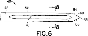
図5乃至図8を参照すると、ドリル40のシャフト42の先端50は、ボーリングチップ60を含む。このチップは、好ましくは、ボーリングチップを中心として互いから約120°のところに配置されており且つ尖端68までテーパした三つの切断縁部62、64、66を含む。テーパは、長さ方向軸線AS に対して約13°である。更に、及び本発明の好ましい特徴によれば、先端50には、固定ピン12を案内する横方向ガイド溝70が設けられている。このガイド溝70は、基端傾斜部分72及び先端湾曲変向部分74を含む。傾斜部分は、好ましくは、傾斜部分70の表面76に対して垂直な線LP が、シャフト42の軸線AS に対して垂直な線LS に対して約5°乃至8°の角度をなすように傾斜している。湾曲部分74は、好ましくは、約12.7mm(約0.50インチ)の半径を有する。好ましい実施例では、ガイド溝70は、好ましくはシャフト42内に延びており、傾斜部分72と湾曲部分74との交差部での溝深さDG は、約2.795mm(約0.110インチ)であり、好ましくは、幅WG は、約1.600mm(約0.063インチ)である。溝深さDG は、好ましくはピン12の直径以上であり、案内溝70でのピン12及びシャフト42の組み合わせ直径は、シャフトの外径以下である(図13参照)。幅WG は、ピンが結着することなく正確に案内されるように、好ましくはピンの直径よりも0.0508mm乃至0.0762mm(0.002インチ乃至0.003インチ)だけ大きい。
【0021】
図1乃至図4、図9乃至図11、及び図14及び図15を参照すると、ピンハンドル18は、主ハンドル16のピンハンドルスロット30内を摺動自在に移動するように大きさ及び形状が定められた先端部分80、及び主ハンドル16のピンハンドルボア32内を摺動自在に移動するように大きさ及び形状が定められた基端部分82を含む。先端部分80の下領域84には、ピンハンドル18を医師の指で主ハンドル16に対して容易に移動できるようにする複数の窪み86が設けられている。ピンハンドル18の先端88には面取りが施してあり、固定ピン12が好ましくは締まり嵌めで固定されるボア90が設けられている。ピンハンドル18もまた、主ハンドル16と同様に、好ましくは、ABS、ナイロン、ポリカーボネート、又はポリエチレン等のプラスチックから型成形されるが、デルリンロッド又は同様の材料から機械加工で形成できる。
【0022】
図2及び図12に示すように、固定ピン12は、好ましくは、端部がピンハンドル18の先端88に固定された実質的に直線状の基端部分92、この基端部分92に対して随意に角度を付けることができる実質的に直線状の中央部分94、及び好ましくは尖っていないチップ98を持つ湾曲した先端部分96を含む。基端部分92及び中央部分94が互いに対して角度をなす場合には、この角度は約5°乃至8°であるのが好ましい。先端チップ96は、好ましくは、約12.7mm(約0.50インチ)の半径で約33°に亘って湾曲している。固定ピン12は、好ましくは、中実の金属製ワイヤ材料、例えばステンレス鋼でできている。固定ピンは、骨折部の定着に十分な剛性を備えているけれども、ピン12を以下に説明するように骨の髄管に挿入するのに十分に曲げることができるのに十分弾性的に撓むことができなければならないということは理解されよう。従って、システム10は、様々な直径の複数の固定ピン12を含む。一つの好ましい固定ピン12は、好ましくは約152.4mm(約6.0インチ)の長さを持ち、約17.78mm(約0.70インチ)がピンハンドル18の先端ボア90内に固定され、及び約1.524mm(約0.060インチ)の直径を有する。
【0023】
次に、図1、図13、及び図14を参照すると、固定ピン12がピンハンドル18に位置決めされており、ピンハンドル18は、固定ピン12の湾曲した先端部分96がドリル40のシャフト42のガイド溝70内に載止し、先端部分96がシャフトの周囲輪郭を越えて延びないように、主ハンドル16内に収容されている。図14を参照すると、ピンハンドル18を主ハンドル16のピンハンドルスロット30及びピンハンドルボア32内で主ハンドルに対して先端方向に移動することにより、固定ピン12の先端部分96をドリル40のシャフト42に対してガイド溝70を通して、ボーリングチップ60を越えて、シャフトAS の軸線に対して所定角度で移動する。ピンハンドルは、主ハンドルに連結されたまま、ピンの先端をシャフトの先端を越えて好ましくは少なくとも(1/4インチ)、更に好ましくは25.4mm乃至76.2mm(1インチ乃至3インチ)延ばすように移動できる。更に、ピンハンドル18の主ハンドル16に対する先端方向移動、即ち主ハンドルのピンハンドルに対する基端方向移動の邪魔になる妨げがないということは理解されよう。このように、図15に示すように、ピンハンドルは主ハンドルから分離できる。
【0024】
使用にあたっては、器具14の主ハンドル16を手で操作し、ドリル40のボーリングチップ60を骨折した中手骨のベースに皮下導入する。ひとたびドリル40のボーリングチップ60が中手骨のベースに進入した後、中手骨の髄管の自然の中空を通して固定ピン12を案内するようにガイド溝70が配向されるようにドリルを配向する。次いで、ピンハンドル18を主ハンドル16に対して手動で移動し、固定ピン12の湾曲した先端部分96を骨に押し込む。次いで、主ハンドル16をピンハンドル18に対して基端方向に移動し、ドリル40を骨から除去し、主ハンドルをピンハンドルから係合解除する。これは、好ましくはピンハンドル及びこれに取り付けられた固定ピンをその現在の位置に残したまま行われる。次いで、ピンハンドルを操作し、ピンを、骨折した中手骨の髄管を通して、ピンが骨折部の両側に延びるまで移動し、骨折した骨の必要な定着を提供する。固定ピン及び溝が相補的形状をなしている(ピンの基端部分に対するピンの中央部分の5°乃至8°の角度が、溝の基端部分の5°乃至8°の角度と実質的に同じであり、ピンの先端部分の12.7mm(0.50インチ)の曲率半径が、溝の先端部分の12.7mm(0.50インチ)の曲率半径と実質的に同じである)ため、固定ピンが髄管内に容易に差し向けられるということは理解されよう。固定ピン12のチップ98の先が尖っていないため、ピンが中手骨の先端を穿刺することがない。最後に、骨折した骨が固定ピンで適正に固定されていることを外科医が確認した後、ピンハンドル18を操作して固定ピン12を皮膚の進入穴と隣接して曲げ、ピンを切断し、切断した端部を皮下で着座するか或いは皮膚の外側の包帯で覆う。骨折が治癒した後、固定ピンを例えばプライヤーで骨から引き出し、次いで廃棄する。次いで皮膚入口穴を治癒する。
【0025】
本発明の骨折固定システムは、中手骨の骨折に対して実質的固定を提供するが、不当な浸襲度又は多数の工程を必要としないということは理解されよう。更に、本方法は、適切な治癒に十分に骨折部を定着するのに必要な医師の「手数」を浸襲手術に対して減少する。
【0026】
次に図16を参照すると、この図には、第1実施例と実質的に同様の(同様の部品には200を加えた同じ参照番号が附してある)、骨折固定システム210用の器具214の第2実施例が示してある。この器具214は、先端ガイド溝270及び先が尖ったボーリング端部260を持つシャフト240を含む。シャフト240は、シャフトを操作するためのシャフトハンドル216を含む。シャフトハンドル216は、ピンハンドル218を摺動自在に受け入れるスロット230を含む。スロット230は、好ましくは、シャフトに向かって下方に傾斜している。シャフトハンドル216には、シャフトハンドル216を医師の手で安定的に掴むためのグリップ217が更に設けられている。ピンハンドル218は、シャフトハンドル216のスロット230を通したピンハンドルの相対的先端方向移動を容易にするのに使用できる押縁219を含む。ピンハンドル218及びシャフトハンドル216は、好ましくは、互いに対して積極的に、例えばスナップ嵌めで係合でき、ピンハンドルの押縁219に加えられた十分な力によって係合解除してピンハンドルをシャフトハンドルに対して移動できる。更に、ハンドルが係合解除されており、ピン212のチップ298がシャフト240のボーリングチップ260の僅かに前方に移動されていることの触覚的表示をリリースが提供できる。スロット230が傾斜しているため、スロット230内に配置されたピンハンドルをこのスロット内で移動したとき、ピンハンドル内で軸線方向に設けられた固定ピン212をガイド溝270に向かって及びこの溝を通して差し向けることができる。ピン212は、好ましくは、ピン212がシャフト240に向かって差し向けられるように、シャフトハンドル216の長さ方向軸線方向AS に対して角度をなしている。好ましくは、固定ピン212は、同軸に整合した基端部分292及び中央部分294、及び先が尖っていない、好ましくは湾曲したチップ298が設けられた先端部分296を含む。手術では、シャフト240のボーリング端部260を中手骨に挿入した後、ピンハンドル218をシャフトハンドルに対して先端方向に移動し、ピン212を骨折した骨の髄管内にガイド溝270を通して移動する。次いで、シャフトハンドル216をピンハンドル218から取り外し、ピンハンドルを操作して固定ピンを骨の髄管を通して延ばし、骨を固定する。固定ピンが骨折部を所望の通りに固定した(髄管内で直径方向に十分に嵌着した)ことを医師が確認した後、ピンを皮膚表面で曲げ、切断する。
【0027】
医師は、固定ピンを髄管に挿入した後(しかしピンを曲げて切断する前)、挿入したピンの大きさが特定の患者にとって不適当であると判断し、直径が異なる固定ピンを必要とする場合がある。この目的のため、様々な大きさ(例えば実質的に1.524mm(0.060インチ)、実質的に1.295mm(0.051インチ)、実質的に1.143mm(0.045インチ)、実質的に0.965mm(0.038インチ)、及び実質的に0.889mm(0.035インチ))の先端部分を持つ固定ピンを含む一組の固定ピンを、医師が使用するために提供する。しかしながら現在手に挿入されているピンを交換のために手から取り出す場合、骨の入口穴の位置を変えるのは困難である。従って、図17に示すように、補助的再ガイド工具300を本発明のシステムに提供するのがよい。再ガイド工具300は、ハンドル302、このハンドルの一端306から延びる、前縁308を持つスロット付きシャフト304、及びハンドルの他端312から延びるチューブ状曲げ部分310を含む。ハンドル302には、好ましくは、医師の親指を置くことができることによりハンドルを掴み易くする窪み314が更に設けられている。
【0028】
再ガイド工具300のスロット付きシャフト304は、医師が交換しようとする工具ピン上に手の入口穴を通して骨の穴内に延ばすことができる。前縁308が傾斜しているため、シャフトが手の傷口を通して容易に挿入され、その領域に残す傷が最小になる。スロット付きシャフト設計は、皮膚の入口穴から骨までの通路を維持する、骨シャフト(ドリル)の先端を再挿入するよりも傷が少ないということは理解されよう。次いで、工具ピンを取り出すことができる。この際、スロット付きシャフト304は交換ピン用のガイドとして作用する。最終的に適正な固定ピンを決定した後、ピンを切断し、再ガイド工具300を逆にし、切断したピン上に曲げ部分310を延ばし、これに続いて皮下的に着座させるため、曲げ部分を使用して梃の作用でピンを曲げる。ガイド工具300は、最も適当には、本発明の第1及び第2の実施例(これらの実施例には横方向ピンガイドが設けられている)で使用されるが、ガイド工具は、以下の実施例のうちの任意の実施例でも使用できるということは理解されよう。
【0029】
次に図18を参照すると、この図には、本発明による骨折固定システム410用の器具414の第3実施例が示してある。器具414は、軸線方向通孔424を持つシャフトハンドル416、及びその先端に連結されたボーリングシャフト440を含む。シャフト440はカニューレになっている。即ち、シャフト440には内部通路470が設けられており、好ましくは軸線方向通路出口471及び好ましくは先が尖った環状切断縁部473を持つ先端チップ460を含む。軸線方向通孔424及び内部通路470は互いに連通しており、好ましくは軸線方向で整合している。基端ハンドル421が設けられたロッド状突き錐419は、通路470を通して延ばすことができ、及び通路470から取り外すことができる。突き錐419は、好ましくは、そのハンドル421をシャフトハンドル416に面一に着座させた場合にそのチップ423が通路出口471を通って延び、ボーリングチップとして作動する長さを有する。骨に挿入するため、内突き錐及びシャフトを互いに係止できる。次いで、固定ピン412を通路470を通して供給できるようにするため、及び通路出口471から出す(図19参照)ため、突き錐を係止解除し、内部通路470から取り出す。
【0030】
使用に当たっては、突き錐ハンドル421及びシャフトハンドル416を使用し、突き錐419のチップ423及びシャフト440のチップ460を中手骨に挿入する。次いで、突き錐ハンドル421を通路470から取り外し、固定ピン412を通路を通して操作し、髄管に入れる。固定ピンを髄管内に十分に延ばして骨を骨折部の両側で固定した後、主ハンドル416をピン412を越えて手前側に取り外す。次いでピンを更に操作し、最終的に所望の長さに切断する。
【0031】
次に図20を参照すると、この図には、骨折固定システム510用の器具514の第4実施例が示してある。器具514は、通孔524を持つ主ハンドル516及びこのハンドルの先端に連結されたボーリングシャフト540を含む。ボーリングシャフト540はカニューレになっており、その先端には先の尖ったボーリング先端チップ560及び横方向通路出口571が設けられている。通路570内には、通路出口571を閉鎖することにより、骨内へのシャフト540の挿入を容易にするように、ロッド(図示しないけれども、第2実施例に関して説明した突き錐と同様である)が設けられているのがよい。ロッドは、設けられている場合には、これに続いて取り外される。次いで、固定ピン512を通路570を通して中手骨の髄管内に延ばす。
【0032】
次に図21を参照すると、この図には、骨折固定システム610用の器具614の第5実施例が示してある。器具614は、カニューレ状ボーリングシャフト640を含む。このシャフトには、好ましくは、基端シャフトハンドル616及び固定ピン612が設けられている。固定ピン612の基端には、随意であるが、ピンハンドルが設けられている。カニューレ状シャフト640は、シャフト640の軸線方向通路670に続く基端横方向ピン入口669、及びピンを髄管内に案内するように配向された先端横方向通路出口671を含む。随意であるが、通路出口671は、ピンを軸線方向に案内するため、通路670と軸線方向に整合している。シャフト640を中手骨に挿入した後、ピン612をシャフト640を通して骨折した骨の髄管内に操作し、骨を固定する。ピンハンドルが設けられていない場合には、シャフト640及びシャフトハンドル616をピン612を越えて基端方向に引っ張り、ピンを操作する。ピンの操作は、ピンが十分に挿入され、曲げられ、及び最終的に所望の長さに合わせて切断されるように行われる。随意のピンハンドル618を使用する場合には、シャフト640をピン612を越えて手前側に移動し、ピンを更に操作し、所望の長さに合わせて切断する。
【0033】
次に図22を参照すると、上述の実施例の各々で使用された固定ピンの形態の別の態様が示してある。例えば、固定ピン712には、チップ720と隣接して狭幅部分722(即ち縮径部分)が設けられており、好ましくは、この部分の周囲にコイル724が位置決めされている。この形体により、固定ピンの先端718は更に容易に曲がるようになり、固定ピンが、好ましくは自己案内で髄管に従って移動するようになる。更に、ステンレス鋼に対する別態様として、ピン712は、チタニウム、又は他の構造的支持性を持つ生体親和性材料で形成できる。
【0034】
次に図23を参照すると、固定システム810のピンハンドル818には一組の固定ピンが提供される。これらのピンは、実質的に第1実施例に関して上文中に説明したのと同様であるが、様々な先端寸法を有する。例えば、先端直径が中手骨について望ましいよりも比較的小さいピン812を指節骨髄管に挿入するのが望ましい。しかしながら、ピンハンドル818を容易に収容できるようにするため、及び様々な先端寸法のピンを安定的に保持するため、ピンの基端部分892の寸法には、好ましくは均等な寸法が設けられる。このように、幾つかの固定ピン812は、ピンの基端部分892に沿って夫々の先端寸法まで先端方向にテーパした部分813(又は別の態様では、破線で示す段813a)を備えているのがよい。
【0035】
次に図24を参照すると、固定システムは、互いに対する大きさが同じであるか或いは異なる複数の又は組900をなした固定ピン912a、912b、912cを含む。個々のピンの各々は、骨の髄管よりも小さいが、必要な固定を提供するために組のうちの一つ又はそれ以上の他のピンを埋め込むと、ほぼ髄管の内径と等しい固定システムが提供される。図25を参照すると、ピンは、骨折した骨の髄管に、実質的に上文中に説明したように、即ちガイド溝を持つシャフトを含み且つシャフトを操作するためのシャフトハンドルが設けられ、ピンハンドルがピンの基端に連結された器具を使用して個々に挿入される。第1ピン912aをピンハンドルに設置し、骨915の髄管913に挿入し、上文中に説明したように骨の骨折部911を横切って延長する。第2ピン912bを第1ピン912aの側方に沿って挿入し、随意の追加のピン、例えばピン912cを、同様に挿入する。ピンの先端は、末広がりになって、図示のように骨の様々な部分に載止し又は埋め込まれるか或いは、実質的に整合した状態を保持する。図25及び図26を参照すると、円筒形コレット917を、次いで、ピンの露呈された基端上に位置決めし、ピンの相対的軸線方向回転を実質的に阻止するようにピンを互いに拘束する。コレット917は、好ましくは、ピンを安定的に固定するようになった中央開口部919を含む。例えば、3本のピンについては、中央開口部919は、3本のピンを互いに保持するようになった直径を持つ円形であるのがよい。更に、コレット917は、好ましくは、コレット及び従って固定ピンの基端を骨折した骨に固定するための手段、例えば雄ねじ及び好ましくはセルフタッピングねじ921を含む。好ましくは、コレットを骨の所望の深さに着座するのを補助するようになった外フランジ923が更に設けられている。このように、固定システムは骨折部に捩じり安定性を提供する。
【0036】
次に図27及び図28を参照すると、別の捩じり安定化骨折固定システムでは、二つのピン1012a、1012bを骨1015に挿入し、骨折部1011を上文中に説明したように橋渡しする。三つの開口部1019a、1019b、1019cを持つコレット1017(又は図29に示すように単一のクローバー形状の開口部1119を持つコレット1117)をピンの基端に設ける。ピンは、これらの開口部のうちの二つの開口部1019a、1019bを通って延びる。残りの開口部1019cは、コレット1017を骨に対して定着するために釘1121を骨に固定するために用いられる。
【0037】
本明細書中に骨折固定システムの幾つかの実施例を説明し例示した。本発明の特定的な実施例を説明したけれども、これは、本発明をこれらの実施例に限定しようとするものではなく、本発明は当該技術が許す限りにおいて広く、本明細書もそのように読まれるべきである。かくして、固定システムの幾つかの実施例を特に骨折した中手骨の固定について説明したが、本システムは、骨折部の固定に関して同様の問題点が存在する同様の又は比較的小さな骨、例えば足の中足骨及び指及び爪先の指節骨の固定に使用できる。更に、小児の腕骨、例えば尺骨及び橈骨を同様に治療できる。従って、本発明の教示は、本発明のシステムの同様の骨に関する使用についてである。更に、本発明のシステムの様々な構成要素に関して特定の材料を開示したが、他の適当な材料を同様に使用できるということは理解されよう。例えば、金属製固定ピンを説明したが、固定ピン用の金属程には好ましくない別の材料は、非金属、詳細には生体吸収性材料である。例えば、特定の寸法及び角度を開示し、これが優れた結果をもたらしたが、システムで中手骨等を定着するために使用されるようになっている限り、構成要素の大きさを他の適当な寸法及び角度にできるということは理解されよう。例えば固定ピンの先端部分及び溝の先端表面は、両方とも、好ましくは5°乃至8°の角度が付けてあるが、他の適当な角度、例えば3°乃至15°を使用することもできる。更に、指で掴むための手段として窪みを開示したが、指で掴むための他の手段、例えばローレット目、押縁、溝、及びこぶを追加に又は代替として使用できる。更に、骨ボーリングシャフト構成要素を第1実施例でドリルとして説明したが、シャフト構成要素に何等かの切断縁部を設ける必要はなく、骨に進入するための尖端が設けられていてもよいということは理解されよう。更に、固定ピンをシャフト構成要素に対して移動するための機械加工を施したハンドルが開示されているが、プライヤー等を同様に使用してピンを保持しピンをシャフトのガイド手段を通って移動するということは理解されよう。更に、ドリルシャフトを主ハンドルに保持するためのピンを説明したが、ドリルをハンドルに固定するための他の手段を使用できるということは理解されよう。更に、ピンの基端を互いに保持する円筒形コレットを示したが、ピンの端部を互いに拘束するために形状及び形体が異なる装置を同様に使用できるということは理解されよう。例えば、スリーブ、バンド、クリップ、ステープル、等を使用できる。更に、一実施例では、コレットを通って延びる釘を示したが、ねじ又は同様のファスナを同様に使用できるということは理解されよう。従って、本発明に対し、特許請求の範囲の精神及び範疇から逸脱することなく、更に他の変向を行うことができるということは当業者には理解されよう。
本発明の実施態様は以下の通りである。
(1)人間の骨の骨折を安定化するための骨折固定システムにおいて、
a)基端及び先端を持ち、骨の髄管内にぴったりと嵌まる大きさになっており、骨折を定着するのに十分な剛性及び髄管への挿入を容易にするために曲げることができるのに十分な可撓性を有する固定ピン、及び
b)基端と、骨に穴を穿つためのボーリング手段が設けられた先端と、前記固定ピンを髄管内に案内するために前記先端と隣接して設けられた手段とを含む細長いシャフトを有し、
前記固定ピン及び前記シャフトは、両方とも、前記固定ピンの前記先端が前記シャフトの前記先端を越えて移動できるようになっている、骨折固定システム。
(2)c)前記固定ピンの前記シャフトに対する前記ピンガイドを通した移動を容易にする、前記固定ピンの前記基端に連結された第1ハンドルを更に含む、実施態様(1)に記載の骨折固定システム。
(3)前記第1ハンドルは、髄管内への前記固定ピンの移動を容易にする、指が係合できる構造を備えている、実施態様(2)に記載の骨折固定システム。
(4)d)骨内への前記シャフトの移動を容易にするため、前記シャフトの前記基端に連結された第2ハンドルを更に含む、実施態様(2)に記載の骨折固定システム。
(5)前記第2ハンドルには、前記第1ハンドルを先端方向に摺動自在に受け入れる長さ方向開口部が設けられている、実施態様(4)に記載の骨折固定システム。
(6)前記第2ハンドルは、前記長さ方向開口部から取り外すことができる、実施態様(5)に記載の骨折固定システム。
(7)前記第2ハンドルは、前記スロット内に取り外し自在に係合できる、実施態様(5)に記載の骨折固定システム。
(8)前記ピンガイドは、前記シャフトの前記先端に又は先端と隣接して前記シャフトに設けられた溝である、実施態様(1)に記載の骨折固定システム。
(9)前記溝は、傾斜した基端面及び湾曲した先端面を含む、実施態様(8)に記載の骨折固定システム。
(10)前記ボーリング手段は、尖端で合一する複数の切断縁部を含む、実施態様(1)に記載の骨折固定システム。
(11)前記ピンガイドは、前記シャフトに設けられた先端軸線方向出口ボアである、実施態様(1)に記載の骨折固定システム。
(12)前記シャフトは、前記出口ボアの周囲に切断縁部を有する、実施態様(11)に記載の骨折固定システム。
(13)前記ピンガイドは、前記シャフトに設けられた先端横方向出口ボアである、実施態様(1)に記載の骨折固定システム。
(14)前記第1ハンドル及び前記第2ハンドルのうちの少なくとも一方には、人の手で掴むための手段が設けられている、実施態様(5)に記載の骨折固定システム。
(15)前記第2ハンドルには通孔が設けられており、前記シャフトは前記通孔と連通した軸線方向通路を含み、前記固定ピンは、前記通孔及び前記軸線方向通路を通して軸線方向に移動自在である、実施態様(5)に記載の骨折固定システム。
(16)前記シャフトの前記軸線方向通路は、前記シャフトの前記先端に又は先端と隣接して軸線方向出口及び横方向出口の一方を含む、実施態様(15)に記載の骨折固定システム。
(17)前記シャフトは、通路、この通路内への横方向基端入口、及び前記通路からの先端出口を含み、前記固定ピンは、前記横方向入口、前記通路、及び前記出口の一方を通って延びるようになっている、実施態様(1)に記載の骨折固定システム。
(18)前記出口は、前記シャフトの横方向部分及び軸線方向部分のうちの一方に設けられている、実施態様(1)に記載の骨折固定システム。
(19)d)前記固定ピン上に装着する大きさの横方向開口部を持つスロットが設けられたシャフトを持つガイド工具を更に含む、実施態様(4)に記載の骨折固定システム。
(20)前記固定ピンは、基端部分、中央部分、及び湾曲した先端部分を持つ細長いロッドを含む、実施態様(1)に記載の骨折固定システム。
(21)前記基端部分は直線状であり、前記中央部分は直線状である、実施態様(20)に記載の骨折固定システム。
(22)前記中央部分は、前記基端部分に対して所定の角度をなしている、実施態様(20)に記載の骨折固定システム。
(23)前記角度は5°乃至8°であり、前記湾曲した先端部分は、約12.7mm(約0.5インチ)の曲率半径を有する、実施態様(22)に記載の骨折固定システム。
(24)前記固定ピンの前記先端には、実質的に尖っていないチップが設けられている、実施態様(1)に記載の骨折固定システム。
(25)前記固定ピンには、前記固定ピンの前記先端と隣接して縮径部分が設けられている、実施態様(1)に記載の骨折固定システム。
(26)前記縮径部分の周囲にコイルが設けられている、実施態様(25)に記載の骨折固定システム。
(27)前記固定ピンは、人間の中手骨、人間の中足骨、人間の指節骨、小児の尺骨、及び小児の橈骨のうちの一つの髄管に嵌まる大きさになっている、実施態様(1)に記載の骨折固定システム。
(28)人間の中手骨、中足骨、又は指節骨の骨折を安定化するための骨折固定システムにおいて、
a)基端及び先端を持ち、中手骨、中足骨、又は指節骨の髄管内にぴったりと嵌まる大きさになっており、骨折を定着するのに十分な剛性及び髄管への挿入を容易にするために曲げることができるのに十分な可撓性を有する固定ピン、
b)基端と、先端と、この先端と隣接した出口を持つ、前記固定ピンを受け入れるようになった軸線方向通路と、前記固定ピンを髄管内に案内するため、前記シャフトの前記先端と隣接した手段と、基端ハンドルとを含む細長いシャフト、及び
c)前記軸線方向通路内を延びる大きさを持つ、前記軸線方向通路から基端方向に取り外すことができる、基端ハンドルを持つロッドを有し、
前記固定ピン及び前記シャフトは、両方とも、前記ロッド部材を前記軸線方向通路から取り外して前記固定ピンを前記軸線方向通路内に設置したときに前記固定ピンの前記先端が前記シャフトの前記先端を越えて少なくとも6.35mm(1/4インチ)移動できるようになっている、骨折固定システム。
(29)前記ロッド部材はボーリングチップを有する、実施態様(28)に記載の骨折固定システム。
(30)前記ロッド部材は、前記シャフトに対して軸線方向に係止できる、実施態様(28)に記載の骨折固定システム。
(31)人間の中手骨、中足骨、又は指節骨の骨折を安定化するための骨折固定システムにおいて、
a)基端及び先端を持ち、中手骨、中足骨、又は指節骨の髄管内に嵌まる大きさになっており、骨折を定着するのに十分な剛性を有する中実の固定ピン、及び
b)基端と、骨に穴を穿つためのボーリング手段が設けられた先端と、長さ方向軸線と、前記固定ピンを前記シャフトに対して先端方向に移動するとき、前記固定ピンの前記先端を前記シャフトの前記長さ方向軸線に対して所定の角度で偏向するようになった、前記先端と隣接して設けられたピンガイドとを含む細長いシャフトを有する、骨折固定システム。
(32)c)前記固定ピンの前記シャフトに対する前記ピンガイドを通した移動を容易にするため、前記固定ピンの前記基端に連結された第1ハンドル、及びd)前記シャフトの前記基端に連結された第2ハンドルを更に含む、実施態様(31)に記載の骨折固定ピン。
(33)前記ピンガイドは、前記シャフトの前記先端に又はこの先端と隣接して前記シャフトに設けられた溝である、実施態様(31)に記載の骨折固定システム。
(34)前記溝は、傾斜した基端面及び湾曲した先端面を含む、実施態様(33)に記載の骨折固定システム。
(35)人間の中手骨、中足骨、又は指節骨の骨折を安定化するための骨折固定システムにおいて、
a)基端部分及び先端部分を持ち、中手骨、中足骨、又は指節骨の髄管内に嵌まる大きさになっており、前記先端部分は非直線状形状を有する固定ピン、及び
b)基端部分と、ボーリングチップを持つ先端部分と、長さ方向軸線と、前記先端部分に設けられた、前記ボーリングチップが中手骨、中足骨、又は指節骨に進入し、前記固定ピンを前記シャフトに対して先端方向に移動したときに前記固定ピンを中手骨、中足骨、又は指節骨の髄管内に前記長さ方向軸線に対して所定の角度で案内するように、前記固定ピンの前記先端部分の前記非直線状形状とほぼ同様の非直線状形状を画成するピンガイドとを含む細長いシャフトを有する、骨折固定システム。
(36)前記固定ピンの前記先端部分の前記非直線状形状は、直線状基端第1部分及び湾曲した先端第2部分を含む、実施態様(35)に記載の骨折固定システム。
(37)前記ピンガイドは、前記シャフトに設けられた溝を含み、前記溝は、前記長さ方向軸線に対して約5°乃至8°の角度をなす第1部分及び約12.7mm(約0.5インチ)の曲率半径を持つ第2部分を持つ表面を含む、実施態様(36)に記載の骨折固定システム。
(38)前記先端部分の前記第1部分は、前記固定ピンの前記基端部分に対して約5°乃 至8°の角度をなしており、前記先端部分の前記第2部分は約12.7mm(約0.5インチ)の曲率半径を有する、実施態様(37)に記載の骨折固定システム。
(39)c)前記固定ピンの前記シャフトに対する前記ピンガイドを通る移動を容易にする、前記固定ピンの前記基端に連結された第1ハンドル、及びd)前記シャフトの前記中手骨内への移動を容易にする、前記シャフトの前記基端に連結された第2ハンドルを更に含む、実施態様(35)に記載の骨折固定システム。
(40)人間の中手骨、中足骨、又は指節骨の骨折を安定化するための骨折固定システムにおいて、
a)基端及び先端を持ち、中手骨、中足骨、又は指節骨の髄管内に嵌まる大きさになっており、骨折を定着するのに十分な剛性及び髄管への挿入を容易にするために曲げることができるのに十分な可撓性を有する中実の固定ピン、及び
b)基端と、中手骨、中足骨、又は指節骨に穴を穿つためのボーリング手段が設けられた先端と、長さ方向軸線と、前記固定ピンを髄管内に案内するためのガイド手段とを含むシャフト、及び
c)前記固定ピンの前記先端が実質的に前記シャフトの前記先端を越えて延びるように、前記固定ピンを、前記シャフトに対して前記ガイド手段を通して先端方向に移動するハンドルを含む、骨折固定システム。
(41)前記ガイド手段は、前記固定ピンを髄管内に前記ボーリング手段の前記長さ方向軸線に対して所定の角度で案内するための手段である、実施態様(40)に記載の骨折固定システム。
(42)前記固定ピン及び前記ガイド手段は、相補的な非直線状形状を備えている、実施態様(40)に記載の骨折固定システム。
(43)基端と、骨折した中手骨、中足骨、又は指節骨のベースに穴を穿つためのボーリング手段を持つ先端と、中手骨、中足骨、又は指節骨の髄管内に前記固定ピンを案内するためのガイド手段とを含むシャフトを有する、骨折固定システム用の固定ピンにおいて、
中手骨又は中足骨の髄管を通って延びるように直径方向の大きさが定められた中実のワイヤであって、骨折部を定着するのに十分な剛性を持ち、骨のベースに設けられた穴内にこの穴を通して及び髄管を通して前記ワイヤを曲げることができるのに十分な可撓性を持ち、基端部分、直線状中央部分、及び湾曲した先端部分を有し、前記中央部分が前記基端部分に対して角度をなしており、前記先端部分には約12.7mm(約0.5インチ)の曲率半径が設けられている中実のワイヤを含む、固定ピン。
(44)前記固定ピンの前記先端部分は、実質的に尖っていないチップを有する、実施態様(43)に記載の固定ピン。
(45)前記中央部分は前記基端部分に対して3°乃至15°の角度をなしている、実施態様(43)に記載の固定ピン。
(46)前記中央部分は前記基端部分に対して5°乃至8°の角度をなしている、実施態様(43)に記載の固定ピン。
(47)基端と、骨折した中手骨、中足骨、又は指節骨のベースに穴を穿つためのボーリング手段を持つ先端と、中手骨、中足骨、又は指節骨の髄管内に前記固定ピンを案内するためのガイド手段とを含むシャフトを有する、骨折固定システム用の固定ピンにおいて、
中手骨、中足骨、又は指節骨の髄管を通って延びるように直径方向の大きさが定められたワイヤであって、骨折部を定着するのに十分な剛性を持ち、基端部分、先端を持つ先端部分を有し、前記先端部分は、前記先端と隣接して縮径部分を有するワイヤを含む、固定ピン。
(48)前記縮径部分の周囲にコイルが設けられている、実施態様(47)に記載の固定ピン。
(49)骨の骨折を安定化するための骨折固定システムにおいて、
a)基端及び先端を各々有する複数の固定ピンであって、各々が骨の髄管内に互いに嵌まる大きさになっており、骨折を定着するのに十分な複合剛性を有し、髄管内への挿入を容易にするために前記複数の固定ピンの各々を曲げることができるのに十分な個々の可撓性 を持つ、複数の固定ピン、及び
b)基端と、骨に穴を穿つためのボーリング手段が設けられた先端と、前記固定ピンの各々を髄管内に案内するために前記先端と隣接して設けられた手段とを含む細長いシャフトを有し、
前記固定ピン及び前記シャフトは、両方とも、前記固定ピンの前記先端が前記シャフトの前記先端を越えて移動できるようになっている、骨折固定システム。
(50)c)前記固定ピンのうちの一つの固定ピンの前記シャフトに対する前記ピンガイドを通した移動を容易にする、前記固定ピンのうちの一つの固定ピンの前記基端に連結された第1ハンドルを更に含む、実施態様(49)に記載の骨折固定システム。
(51)前記第1ハンドルは、前記固定ピンのうちの一つの固定ピンの髄管内への移動を容易にする、指が係合できる構造を備えている、実施態様(50)に記載の骨折固定システム。
(52)前記ピンガイドは、前記シャフトの前記先端に又は先端と隣接して前記シャフトに設けられた溝である、実施態様(49)に記載の骨折固定システム。
(53)前記溝は、傾斜した基端面及び湾曲した先端面を含む、実施態様(52)に記載の骨折固定システム。
(54)前記ボーリング手段は、尖端で合一する複数の切断縁部を含む、実施態様(49)に記載の骨折固定システム。
(55)前記複数の固定ピンは、第1先端直径を持つ少なくとも一つの固定ピン及び前記第1先端直径と異なる第2先端直径を持つ少なくとも一つの固定ピンを含む、実施態様(49)に記載の骨折固定システム。
(56)前記複数の固定ピンの各々は、約0.889mm乃1.524mm(約0.035インチ乃至0.060インチ)の先端直径を有する、実施態様(55)に記載の骨折固定システム。
(57)前記ピンのうちの少なくとも一つのピンは、第1直径を持つ基端部分及び前記第1直径よりも小さい第2直径を持つ先端部分を有する、実施態様(49)に記載の骨折固定システム。
(58)c)前記固定ピンの前記基端を互いに固定するための手段を更に含む、実施態様(49)に記載の骨折固定システム。
(59)前記固定手段は、更に、前記固定ピンを骨に固定する、実施態様(58)に記載の骨折固定システム。
(60)前記固定手段は、前記固定ピンの前記基端を取り囲むコレット、及び前記コレットを通って骨内に延びるファスナを含む、実施態様(58)に記載の骨折固定システム。
(61)c)前記固定ピンの前記基端を前記骨に固定するための手段を更に含む、実施態様(49)に記載の骨折固定システム。
(62)前記固定手段には、骨と係合するセルフタッピングねじが設けられている、実施態様(61)に記載の骨折固定システム。
(63)前記固定ピンは、人間の中手骨、人間の中足骨、人間の指節骨、小児の尺骨、及び小児の橈骨のうちの一つの髄管内に互いに嵌まるような大きさになっている、実施態様(49)に記載の骨折固定システム。
(64)骨折を安定するための骨折固定システムにおいて、
a)基端部分及び先端部分を持ち、骨の髄管内に嵌まる大きさを備え、前記基端部分は第1直径を有し、前記先端部分は非直線状形状を持ち且つ前記第1直径よりも小さい前記第2直径を有する、固定ピン、及び
b)基端部分と、ボーリングチップを持つ先端部分と、長さ方向軸線と、前記先端部分に設けられたピンガイドとを含み、このピンガイドは、前記シャフトの前記ボーリングチップが骨に進入し、前記固定ピンを前記シャフトに対して先端方向に移動したとき、前記固定ピンを骨の前記髄管内に前記長さ方向軸線に対して所定の角度で案内するように、前記固定ピンの前記先端部分の前記非直線状形状と実質的に同様の非直線状形状を画成する、細長いシャフトを含む、骨折固定システム。
(65)前記ピンは、前記第1直径と前記第2直径との間にテーパ及び段のうちの一方を含む、実施態様(64)に記載の骨折固定システム。
(66)前記固定ピンの前記先端部分の前記非直線状形状は、直線状基端第1部分及び湾曲した先端第2部分を含む、実施態様(64)に記載の骨折固定システム。
(67)前記固定ピンは、人間の中手骨、人間の中足骨、人間の指節骨、小児の尺骨、及び小児の橈骨のうちの一つの髄管内に互いに嵌まるような大きさになっている、実施態様(64)に記載の骨折固定システム。
(68)基端、骨折した骨のベースに穴を穿つためのボーリング手段が設けられた先端、及び前記固定ピンを骨の髄管内に案内するためのガイド手段を持つシャフトを含む、骨折固定システム用の固定ピンキットにおいて、
骨折部を定着するのに十分な剛性、及び骨の前記ベースの穴内にこの穴を通して及び髄管を通して曲げることができるのに十分な可撓性を各々備えた少なくとも二つの中実のワイヤであって、基端部分、直線状中央部分、及び湾曲した先端部分を有し、前記中央部分及び前記先端部分は、骨の髄管を通って延びる直径方向の大きさを有し、前記中央部分は、前記基端部分に対して角度をなしている中実のワイヤを有する、固定ピンキット。
(69)各中実ワイヤの前記先端部分には、約12.7mm(約0.5インチ)の曲率半径が設けられている、実施態様(68)に記載の固定ピンキット。
(70)各中実ワイヤの前記基端部分は第1直径を有し、前記先端部分は比較的小さな第2直径を有する、実施態様(68)に記載の固定ピンキット。
(71)前記中実ワイヤは、前記第1直径と前記第2直径との間にテーパ及び段のうちの一方を含む、実施態様(70)に記載の固定ピンキット。
(72)前記中実ワイヤの前記先端部分は、実質的に尖っていないチップを有する、実施態様(68)に記載の固定ピンキット。
(73)前記中央部分は前記基端部分に対して3°乃至15°の角度をなしている、実施態様(68)に記載の固定ピンキット。
(74)前記先端部分は、約0.889mm乃1.524mm(約0.035インチ乃至0.060インチ)の直径を有する、実施態様(68)に記載の固定ピンキット。
(75)前記固定ピンは、人間の中手骨、人間の中足骨、人間の指節骨、小児の尺骨、及び小児の橈骨のうちの一つの髄管内に互いに嵌まるような大きさになっている、実施態様(68)に記載の固定ピンキット。
【図面の簡単な説明】
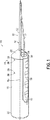
【図1】 骨折固定システムの第1実施例の斜視図である。
【図2】 システムのドリルの先端を断面で示す骨折固定システムの第1実施例の側面図である。
【図3】 本発明の第1実施例の底面図である。
【図4】 本発明の骨折固定システムの端面図である。
【図5】 本発明の骨折固定システムの第1実施例によるドリルの先端の拡大断面図である。
【図6】 本発明の骨折固定システムの第1実施例によるドリルの先端の拡大底面図である。
【図7】 本発明の骨折固定システムの第1実施例によるドリルの先端の拡大端面図である。
【図8】 図7の8−8線での断面図である。
【図9】 図2の9−9線での断面図である。
【図10】 図2の10−10線での断面図である。
【図11】 図2の11−11線での断面図である。
【図12】 本発明の骨折固定システムの固定ピンの側面図である。
【図13】 シャフト先端及び固定ピンの拡大斜視図である。
【図14】 ピンハンドル及び固定ピンを主ハンドル及びドリルに対して部分的に先端方向に移動した形体を示す、本発明の第1実施例のシステムの斜視図である。
【図15】 ピンハンドル及び固定ピンを主ハンドル及びドリルから分離した状態を示す、本発明の第1実施例のシステムの斜視図である。
【図16】 本発明による骨折固定システムの第2実施例の斜視図である。
【図17】 本発明による骨折固定で使用するための補助的再ガイド工具の斜視図である。
【図18】 内突き錐構成要素がシャフトを通って延びた状態で示す、本発明の骨折固定システムの器具の第2実施例の側面図である。
【図19】 内突き錐構成要素の代わりにシャフトを通って延びる固定ピンを示す、器具の第2実施例の側面図である。
【図20】 本発明の骨折固定システムの器具の第3実施例の側面図である。
【図21】 本発明の骨折固定システムの器具の第4実施例の側面図である。
【図22】 本発明の骨折固定システムの固定ピンの変形例の概略図である。
【図23】 骨折固定システムの第5実施例の斜視図である。
【図24】 本発明の第6実施例による一組の固定ピンの側面図である。
【図25】 本発明の第6実施例による捩じりに関して安定化させた固定システムの断面図である。
【図26】 本発明の第6実施例によるコレットの平面図である。
【図27】 本発明の第7実施例による捩じりに関して安定化させた固定システムの断面図である。
【図28】 本発明の第7実施例による第1コレットの平面図である。
【図29】 本発明の第7実施例による第2コレットの平面図である。
【符号の説明】
10 骨折固定システム 12 固定ピン
14 器具 16 主ハンドル
18 ピンハンドル 20 基端
22 先端 24 長さ方向ドリルスロット
26、28 半径方向ボア 30 ピンハンドルスロット
32 ピンハンドルボア 34 窪み
40 定置ドリル 42 シャフト
44 基端 46、48 横方向ボア
50 先端 54、56 ピン[0001]
BACKGROUND OF THE INVENTION
The present invention relates generally to systems for fracture fixation. More particularly, the present invention relates to an improved method and associated system for securing relatively small bone fractures.
[0002]
[Prior art]
Metacarpal fractures are very common. Establishing the metacarpal bone on either side of the fracture is essential for proper healing. However, depending on the position of the fracture, there are some difficulties in ideal establishment.
[0003]
The most frequently used treatment for fixing fractures is splint placement and casting. However, due to the location of the metacarpal bone, such treatment cannot maintain a state in which the metacarpal fracture is properly repaired. It can be firmly fixed by techniques using plates, fixation screws and fixation pins attached by surgical treatment to the damaged bone. Although this type of fracture repair device is a relatively large fracture, such as commonly used in ulna, tibia, or femur fractures, such surgical treatment is generally terribly large. Leave the incision and expose the fracture. Therefore, in many cases, such a technique is judged to have an excessively high degree of penetration for a relatively small and easily broken metacarpal bone.
[0004]
Other techniques have been used that have a low degree of invasion. In this technique, a small incision is made in the proximal skin of the metacarpal bone, a boring tool is inserted through the incision, a small hole is drilled in the metacarpal bone using this boring tool, and the boring tool is removed After that, the doctor supplies the pin through the incision into a small invisible bore in the bone. However, delivering the pin through the skin is a blind operation where there is no means to indicate to the physician the relative position of the pin and the small hole drilled in the bone. Thus, this technique is undesirable for both the physician and the patient because it can cause exacerbated damage to the surrounding tissue by groping out. Furthermore, the embedded pin does not fix with respect to twist the fracture that needs to be fixed with respect to rotation.
[0005]
In addition, similar problems exist with respect to metatarsal fractures and phalanx fractures.
[0006]
[Problems to be solved by the invention]
Accordingly, it is an object of the present invention to provide a fracture fixation system that allows stable fixation for metacarpal, metatarsal, and phalange fractures, and similar bone fractures.
[0007]
Another object of the present invention is to provide a fracture fixation system that provides internal percutaneous fixation for metacarpal, metatarsal, and phalange fractures, and similar bone fractures.
Yet another object of the present invention is to provide a fracture fixation system that provides torsional stability for metacarpal, metatarsal, and phalange fractures, and similar bone fractures.
[0008]
Another object of the present invention is to provide a fracture fixation system that provides a fixation system that is adjustable in size for metacarpal, metatarsal, and phalange fractures, and similar bone fractures. is there.
[0009]
Yet another object of the present invention is to provide a fracture fixation system that has a relatively low degree of invasiveness compared to prior art surgical treatments.
A fracture fixation system is provided in accordance with these objectives, discussed in detail below. For simplicity, the fracture fixation system is generally described with reference to the metacarpal bone, but the system can also be applied to metatarsal bones, phalanges, and similar bones.
[0010]
[Means for Solving the Problems]
According to one embodiment of the present invention, the system includes a fixation pin and an instrument for implanting the fixation pin. According to a first embodiment of the present invention, the instrument includes a main handle and a pin handle movable relative to the main handle. The main handle includes a proximal end, a distal end, and a longitudinal slot having an opening at the distal end of the handle. A boring shaft (drill) is connected to the tip of the main handle. The boring shaft includes a tip guide proximally adjacent to the boring tip for guiding the distal boring tip and the fixation pin into the medullary canal. The pin guide is preferably a groove provided in the shaft. The pin handle is shaped and sized to slidably move within the longitudinal slot and is provided with a tip bore that receives the finger grip and the fixed pin therein. The fixation pin preferably includes a substantially straight proximal and central portion and a distal portion preferably provided with a non-sharp tip. First, the curved tip portion rests in the pin guide of the boring shaft. It will be appreciated that when the pin handle is moved relatively distally within the slot of the main handle, the distal portion of the fixed pin moves through and beyond the pin guide.
[0011]
In use, the main handle of the instrument is manipulated to introduce the boring shaft subcutaneously into the base of the fractured metacarpal bone of the patient's hand. After the shaft tip is introduced into the metacarpal base, it is left in that position, the pin handle is moved distally with respect to the main handle, and the distal end of the fixation pin is pushed into the bone. The pin thereby enters the natural hollow of the medullary canal of the bone. The main handle is then moved proximally relative to the pin handle, the boring shaft is removed from the patient's hand and the main handle is removed from engagement with the pin handle. The pin handle is then further moved and the pin is pushed through the natural hollow of the medullary canal of the fractured metacarpal bone until it extends through the medullary canal to both sides of the fracture and provides the necessary fixation of the fractured bone. . Since the tip of the tip is not sharp, the tip of the metacarpal bone is not punctured. Finally, the proximal end of the pin is bent and cut, preferably seated subcutaneously.
[0012]
According to another embodiment of the device for fracture fixation system, the device includes a shaft handle having a boring shaft connected to the tip. The boring shaft has an internal passage and a tip outlet. The shaft handle includes a through hole communicating with the internal passage of the shaft, and can receive a fixing pin through the through hole. With the handle, the shaft can be manually inserted subcutaneously and rotated to insert the tip of the boring shaft into the metacarpal bone. The tip outlet is provided in the axial direction or in the lateral direction. Optionally, a cone member can be provided in the bore and in the internal passage and extend to the tip outlet of the shaft. This is done to insert the shaft into the metacarpal and then remove the fixation pin to extend through the internal passage and tip outlet of the shaft. According to another embodiment, the bore shaft passage is provided with a proximal lateral outlet and an outlet extending either laterally or axially at the distal end of the shaft.
[0013]
Furthermore, in another aspect, the fixation pin may be self-guided to move according to the medullary canal. The proximal and central portions of the pin are relatively straight and sufficiently rigid (providing fixation while being able to be forced into the bone). A reduced diameter portion is provided adjacent the tip that allows the tip to bend easily relative to the central portion and move along the medullary canal. Preferably, a coil is provided around the reduced diameter portion to provide an apparently constant diameter for the pin.
[0014]
Furthermore, the fixation pin can be adapted to be used with a relatively small medullary canal, particularly as found in the phalanx, i.e. the fixation pin should have a relatively small tip diameter. In order to be able to use such a fixing pin with the same pin handle that is used for a fixing pin adapted to the metacarpal and metatarsal bone, the fixing pin has a proximal diameter with a uniform diameter, diameter Includes a relatively small tip and a tapered or stepped portion between the proximal and distal ends.
[0015]
According to yet another embodiment of the present invention, the fixation system includes a plurality of fixation pins and an instrument for sequentially implanting at least two fixation pins within the medullary canal of a fractured bone. As described above, the instrument is provided with pins that can be individually attached to the pin handle. These pins may be the same diameter or may be provided as a set comprising pins of various diameters. Each individual pin is smaller than the medullary canal of the bone, but is approximately the same as the inner diameter of the medullary canal to provide the necessary fixation when implanted in combination with one or more other pins. Embed each individual pin as described above. At least two pins are implanted to stabilize the fracture. Preferably, a collet is provided on the proximal end of the pin to prevent the pins from rotating relatively by connecting the pins together. Furthermore, the collet is preferably adapted to be connected to the bone in order to anchor the proximal end of the pin to the bone. Thus, the fixation system provides torsional stability of the fracture.
[0016]
Additional objects and advantages of the present invention will become apparent to those of ordinary skill in the art by reference to the following detailed description, taken in conjunction with the accompanying drawings.
[0017]
DETAILED DESCRIPTION OF THE INVENTION
As described above, the present invention will be described with respect to metacarpal fractures, but the present invention is also applicable to fixation of metatarsal and phalange fractures. 1-4, there is shown a metacarpal
[0018]
The
[0019]
The
[0020]
Referring to FIGS. 5-8, the
[0021]
With reference to FIGS. 1-4, 9-11, 14 and 15, the pin handle 18 is sized and shaped to slidably move within the
[0022]
As shown in FIGS. 2 and 12, the securing
[0023]
1, 13, and 14, the fixing
[0024]
In use, the
[0025]
It will be appreciated that the fracture fixation system of the present invention provides substantial fixation for metacarpal fractures, but does not require undue invasiveness or multiple steps. In addition, the method reduces the physician's “hands” required for invasive surgery to establish a fracture sufficiently for proper healing.
[0026]
Reference is now made to FIG. 16, which shows a device for
[0027]
After inserting the fixation pin into the medullary canal (but before bending and cutting the pin), the physician may determine that the size of the inserted pin is inappropriate for a particular patient and requires a fixation pin with a different diameter There is a case. For this purpose, various sizes (eg, substantially 1.524 mm (0.060 inch), substantially 1.295 mm (0.051 inch), substantially 1.143 mm (0.045 inch), A set of fixation pins including a fixation pin having a tip portion of substantially 0.965 mm (0.038 inch) and substantially 0.889 mm (0.035 inch) is provided for use by a physician. To do. However, if the pin that is currently inserted in the hand is removed from the hand for replacement, it is difficult to change the position of the bone entry hole. Accordingly, an
[0028]
The slotted
[0029]
Reference is now made to FIG. 18, which shows a third embodiment of an
[0030]
In use, the
[0031]
Referring now to FIG. 20, there is shown a fourth embodiment of an
[0032]
Referring now to FIG. 21, there is shown a fifth embodiment of an
[0033]
Referring now to FIG. 22, there is shown another aspect of the fixation pin configuration used in each of the above embodiments. For example, the fixed
[0034]
Referring now to FIG. 23, the pin handle 818 of the
[0035]
Referring now to FIG. 24, the fixation system includes a plurality or set 900 of
[0036]
Referring now to FIGS. 27 and 28, in another torsionally stabilized fracture fixation system, two
[0037]
Several embodiments of fracture fixation systems have been described and illustrated herein. Although specific embodiments of the present invention have been described, this is not intended to limit the invention to these embodiments, and the invention is as broad as the art allows, and the present specification as such. Should be read. Thus, although some embodiments of the fixation system have been described with particular reference to fixation of fractured metacarpal bones, the system can be applied to similar or relatively small bones, such as feet, where similar problems exist with respect to fixation of fractures. Can be used to fix the metatarsals and fingers and the phalanges of the toes. In addition, pediatric arm bones, such as the ulna and radius, can be treated similarly. Thus, the teachings of the present invention are for similar bone use of the system of the present invention. Further, while specific materials have been disclosed for the various components of the system of the present invention, it will be understood that other suitable materials can be used as well. For example, while a metal fixation pin has been described, another material that is less desirable than the metal for the fixation pin is a non-metal, specifically a bioabsorbable material. For example, certain dimensions and angles have been disclosed and have provided excellent results, but as long as the system is intended to be used to anchor metacarpal bones, etc. It will be appreciated that any size and angle can be achieved. For example, the tip portion of the fixation pin and the tip surface of the groove are both preferably angled between 5 ° and 8 °, although other suitable angles such as 3 ° to 15 ° can be used. Further, although the indentation has been disclosed as a means for grasping with a finger, other means for grasping with a finger, such as knurled eyes, ridges, grooves, and bumps can be used in addition or as an alternative. Further, although the bone boring shaft component has been described as a drill in the first embodiment, it is not necessary to provide any cutting edge on the shaft component, and it may be provided with a point for entering the bone. It will be understood. Furthermore, a machined handle for moving the fixed pin relative to the shaft component is disclosed, but the pin is held using the pliers or the like as well and the pin is moved through the guide means of the shaft. You will understand that. Furthermore, while pins for holding the drill shaft to the main handle have been described, it will be appreciated that other means for securing the drill to the handle can be used. Furthermore, while a cylindrical collet is shown that holds the proximal ends of the pins together, it will be appreciated that devices of different shapes and configurations can be used to constrain the ends of the pins together. For example, a sleeve, a band, a clip, a staple, etc. can be used. Further, while one embodiment has shown a nail extending through the collet, it will be appreciated that screws or similar fasteners may be used as well. Thus, one of ordinary skill in the art appreciates that further modifications can be made to the present invention without departing from the spirit and scope of the claims.
Embodiments of the present invention are as follows.
(1) In a fracture fixation system for stabilizing fractures of human bones,
a) It has a proximal end and a distal end and is sized to fit snugly within the medullary canal of the bone and can be bent to provide sufficient rigidity to facilitate fracture and easy insertion into the medullary canal A fixing pin having sufficient flexibility, and
b) having an elongated shaft including a proximal end, a distal end provided with a boring means for drilling a hole in the bone, and a means provided adjacent to the distal end for guiding the fixation pin into the medullary canal; And
The fixation pin and the shaft are both fracture fixation systems such that the tip of the fixation pin is movable beyond the tip of the shaft.
(2) The embodiment of claim (1), further comprising: c) a first handle coupled to the proximal end of the fixed pin that facilitates movement of the fixed pin through the pin guide relative to the shaft. Fracture fixation system.
(3) The fracture fixation system according to the embodiment (2), wherein the first handle includes a structure that can be engaged with a finger to facilitate movement of the fixation pin into the medullary canal.
(4) The fracture fixation system according to embodiment (2), further comprising a second handle coupled to the proximal end of the shaft to facilitate movement of the shaft into the bone.
(5) The fracture fixing system according to the embodiment (4), wherein the second handle is provided with a longitudinal opening that slidably receives the first handle in a distal direction.
(6) The fracture fixation system according to embodiment (5), wherein the second handle can be removed from the longitudinal opening.
(7) The fracture fixation system according to embodiment (5), wherein the second handle can be removably engaged in the slot.
(8) The fracture fixing system according to the embodiment (1), wherein the pin guide is a groove provided in the shaft at or adjacent to the tip of the shaft.
(9) The fracture fixation system according to embodiment (8), wherein the groove includes an inclined proximal end surface and a curved distal end surface.
(10) The fracture fixing system according to the embodiment (1), wherein the boring means includes a plurality of cutting edges that are united at a tip.
(11) The fracture fixing system according to the embodiment (1), wherein the pin guide is a distal axial outlet bore provided on the shaft.
(12) The fracture fixation system according to embodiment (11), wherein the shaft has a cutting edge around the outlet bore.
(13) The fracture fixation system according to the embodiment (1), wherein the pin guide is a distal lateral outlet bore provided on the shaft.
(14) The fracture fixation system according to the embodiment (5), wherein at least one of the first handle and the second handle is provided with means for grasping with a human hand.
(15) The second handle is provided with a through hole, the shaft includes an axial passage communicating with the through hole, and the fixing pin moves in the axial direction through the through hole and the axial passage. Fracture fixation system according to embodiment (5), which is free.
(16) The fracture fixation system according to embodiment (15), wherein the axial passage of the shaft includes one of an axial outlet and a lateral outlet at or adjacent to the tip of the shaft.
(17) The shaft includes a passage, a lateral proximal inlet into the passage, and a distal outlet from the passage, and the fixing pin passes through one of the lateral inlet, the passage, and the outlet. The fracture fixation system of embodiment (1), wherein the fracture fixation system is adapted to extend.
(18) The fracture fixing system according to the embodiment (1), wherein the outlet is provided in one of a lateral part and an axial part of the shaft.
(19) d) The fracture fixation system according to embodiment (4), further comprising a guide tool having a shaft provided with a slot having a lateral opening sized to be mounted on the fixation pin.
(20) The fracture fixation system according to embodiment (1), wherein the fixation pin includes an elongated rod having a proximal end portion, a central portion, and a curved distal end portion.
(21) The fracture fixation system according to embodiment (20), wherein the proximal end portion is linear and the central portion is linear.
(22) The fracture fixation system according to embodiment (20), wherein the central portion forms a predetermined angle with respect to the proximal end portion.
(23) The fracture fixation system of embodiment (22), wherein the angle is between 5 ° and 8 ° and the curved tip portion has a radius of curvature of about 0.5 inches.
(24) The fracture fixation system according to the embodiment (1), wherein a tip that is not substantially sharp is provided at the tip of the fixation pin.
(25) The fracture fixing system according to the embodiment (1), wherein the fixing pin is provided with a reduced diameter portion adjacent to the distal end of the fixing pin.
(26) The fracture fixation system according to the embodiment (25), wherein a coil is provided around the reduced diameter portion.
(27) The fixing pin is sized to fit into one medullary canal of a human metacarpal bone, a human metatarsal bone, a human phalanx, a child's ulna, and a child's rib. The fracture fixation system according to the embodiment (1).
(28) In a fracture fixation system for stabilizing a fracture of a human metacarpal bone, metatarsal bone, or phalanx,
a) Has proximal and distal ends and is sized to fit snugly within the medullary canal of the metacarpal, metatarsal, or phalanx, and has sufficient rigidity to anchor the fracture and to the medullary canal A fixing pin that is flexible enough to be bent to facilitate insertion;
b) a proximal end, a distal end, an axial passage adapted to receive the fixation pin, having an outlet adjacent to the distal end, and adjacent to the distal end of the shaft to guide the fixation pin into the medullary canal An elongate shaft including a means and a proximal handle; and
c) a rod having a proximal handle having a size extending in the axial passage and removable from the axial passage in the proximal direction;
In both the fixing pin and the shaft, the tip of the fixing pin exceeds the tip of the shaft when the rod member is removed from the axial passage and the fixing pin is installed in the axial passage. Fracture fixation system that is capable of moving at least 1/4 inch.
(29) The fracture fixation system according to embodiment (28), wherein the rod member has a boring tip.
(30) The fracture fixation system according to embodiment (28), wherein the rod member can be locked in an axial direction with respect to the shaft.
(31) In a fracture fixation system for stabilizing a fracture of a human metacarpal bone, metatarsal bone, or phalanx,
a) A solid fixation pin having a proximal end and a distal end, sized to fit within the medullary canal of the metacarpal bone, metatarsal bone, or phalanx, and having sufficient rigidity to fix a fracture ,as well as
b) a proximal end, a distal end provided with a boring means for drilling a hole in a bone, a longitudinal axis, and the distal end of the fixing pin when the fixing pin is moved in the distal direction with respect to the shaft; A fracture fixation system having an elongate shaft including a pin guide disposed adjacent to the tip, wherein the pin guide is adapted to deflect at a predetermined angle relative to the longitudinal axis of the shaft.
(32) c) a first handle coupled to the proximal end of the fixed pin to facilitate movement of the fixed pin relative to the shaft through the pin guide; and d) at the proximal end of the shaft. The fracture fixation pin of embodiment (31), further comprising a connected second handle.
(33) The fracture fixing system according to the embodiment (31), wherein the pin guide is a groove provided in the shaft at or adjacent to the tip of the shaft.
(34) The fracture fixation system according to embodiment (33), wherein the groove includes an inclined proximal end surface and a curved distal end surface.
(35) In a fracture fixation system for stabilizing a fracture of a human metacarpal bone, metatarsal bone, or phalanx,
a) a fixing pin having a proximal end portion and a distal end portion and sized to fit within a medullary canal of a metacarpal bone, metatarsal bone, or phalanx, and the distal end portion having a non-linear shape;
b) a proximal end portion, a distal end portion having a boring tip, a longitudinal axis, and the boring tip provided at the distal end portion enters the metacarpal bone, metatarsal bone, or phalange, When the fixing pin is moved in the distal direction with respect to the shaft, the fixing pin is guided into the medullary canal of the metacarpal bone, metatarsal bone, or phalanx at a predetermined angle with respect to the longitudinal axis. And a pin guide that defines a non-linear shape substantially similar to the non-linear shape of the distal portion of the fixation pin.
(36) The fracture fixation system according to embodiment (35), wherein the non-linear shape of the distal end portion of the fixation pin includes a linear proximal end first portion and a curved distal end second portion.
(37) The pin guide includes a groove provided in the shaft, and the groove has a first portion having an angle of about 5 ° to 8 ° with respect to the longitudinal axis, and about 12.7 mm (about 12.7 mm). The fracture fixation system of embodiment (36), comprising a surface having a second portion with a radius of curvature of 0.5 inches.
(38) The first portion of the distal end portion is about 5 ° relative to the proximal end portion of the fixing pin. The fracture fixation system according to embodiment (37), wherein the fracture is at an angle of up to 8 ° and the second portion of the tip portion has a radius of curvature of about 0.5 inches.
(39) c) a first handle coupled to the proximal end of the fixation pin that facilitates movement of the fixation pin through the pin guide relative to the shaft; and d) into the metacarpal bone of the shaft. The fracture fixation system according to embodiment (35), further comprising a second handle coupled to the proximal end of the shaft to facilitate movement of the shaft.
(40) In a fracture fixation system for stabilizing a fracture of a human metacarpal bone, metatarsal bone, or phalanx,
a) It has a proximal end and a distal end and is sized to fit in the medullary canal of the metacarpal bone, metatarsal bone, or phalanx, and has sufficient rigidity to insert a fracture and insertion into the medullary canal A solid fixation pin having sufficient flexibility to bendable for ease; and
b) a proximal end, a distal end provided with a boring means for drilling a hole in the metacarpal bone, metatarsal bone or phalanx, a longitudinal axis, and for guiding the fixation pin into the medullary canal A shaft including guide means, and
c) a fracture fixation system including a handle for moving the fixation pin in a distal direction through the guide means relative to the shaft such that the distal end of the fixation pin extends substantially beyond the distal end of the shaft. .
(41) The fracture fixation system according to the embodiment (40), wherein the guide means is means for guiding the fixation pin into the medullary canal at a predetermined angle with respect to the longitudinal axis of the boring means. .
(42) The fracture fixation system according to embodiment (40), wherein the fixation pin and the guide means have complementary non-linear shapes.
(43) a proximal end, a distal end having a boring means for drilling a hole in the base of the fractured metacarpal bone, metatarsal bone, or phalange, and the medulla of the metacarpal bone, metatarsal bone, or phalanx A fixation pin for a fracture fixation system having a shaft including guide means for guiding the fixation pin in a tube,
A solid wire that is diametrically sized to extend through the medullary canal of the metacarpal bone or metatarsal bone, has sufficient rigidity to anchor the fracture and is attached to the base of the bone Flexible enough to be able to bend the wire through this hole and through the medullary canal in a provided hole, having a proximal portion, a straight central portion, and a curved distal portion, said central portion A fixation pin comprising a solid wire that is angled relative to the proximal portion and the distal portion is provided with a radius of curvature of about 0.5 inches.
(44) The fixing pin according to embodiment (43), wherein the tip portion of the fixing pin has a tip that is substantially not sharp.
(45) The fixing pin according to the embodiment (43), wherein the central portion forms an angle of 3 ° to 15 ° with respect to the proximal end portion.
(46) The fixing pin according to embodiment (43), wherein the central portion forms an angle of 5 ° to 8 ° with respect to the proximal end portion.
(47) a proximal end, a distal end having a boring means for drilling a hole in the base of the fractured metacarpal bone, metatarsal bone, or phalange, and the medulla of the metacarpal bone, metatarsal bone, or phalanx A fixation pin for a fracture fixation system having a shaft including guide means for guiding the fixation pin in a tube,
A wire that is diametrically sized to extend through the medullary canal, metatarsal bone, or phalangeal canal, and is rigid enough to anchor the fracture and is proximal A fixing pin comprising: a portion, a tip portion having a tip, wherein the tip portion includes a wire having a reduced diameter portion adjacent to the tip.
(48) The fixing pin according to the embodiment (47), wherein a coil is provided around the reduced diameter portion.
(49) In a fracture fixation system for stabilizing bone fractures,
a) a plurality of fixing pins each having a proximal end and a distal end, each of which is sized to fit within the medullary canal of the bone, and has sufficient composite rigidity to anchor a fracture, Individual flexibility sufficient to allow each of the plurality of fixation pins to be bent to facilitate insertion into A plurality of fixing pins, and
b) an elongate shaft comprising a proximal end, a tip provided with boring means for drilling a hole in the bone, and means provided adjacent to the tip for guiding each of the fixation pins into the medullary canal Have
The fixation pin and the shaft are both fracture fixation systems such that the tip of the fixation pin is movable beyond the tip of the shaft.
(50) c) a first pin connected to the proximal end of one of the fixed pins, which facilitates movement of the fixed pin of the fixed pin through the pin guide with respect to the shaft; The fracture fixation system of embodiment (49), further comprising a handle.
(51) The fracture according to embodiment (50), wherein the first handle includes a structure that can be engaged with a finger to facilitate movement of one of the fixing pins into the medullary canal. Fixing system.
(52) The fracture fixation system according to embodiment (49), wherein the pin guide is a groove provided in the shaft at or adjacent to the tip of the shaft.
(53) The fracture fixation system according to embodiment (52), wherein the groove includes an inclined proximal end surface and a curved distal end surface.
(54) The fracture fixation system according to embodiment (49), wherein the boring means includes a plurality of cutting edges that meet at a tip.
(55) The embodiment (49), wherein the plurality of fixing pins include at least one fixing pin having a first tip diameter and at least one fixing pin having a second tip diameter different from the first tip diameter. Fracture fixation system.
56. The fracture fixation system of embodiment 55, wherein each of the plurality of fixation pins has a tip diameter of about 0.835 mm to 1.524 mm (about 0.035 inch to 0.060 inch).
(57) The fracture fixation according to embodiment (49), wherein at least one of the pins has a proximal end portion having a first diameter and a distal end portion having a second diameter smaller than the first diameter. system.
(58) The fracture fixation system according to embodiment (49), further comprising: c) means for fixing the proximal ends of the fixation pins to each other.
(59) The fracture fixation system according to embodiment (58), wherein the fixation means further fixes the fixation pin to a bone.
(60) The fracture fixation system according to embodiment (58), wherein the fixation means includes a collet surrounding the proximal end of the fixation pin and a fastener extending through the collet into the bone.
(61) Fracture fixation system according to embodiment (49), further comprising means for fixing the proximal end of the fixation pin to the bone.
(62) The fracture fixing system according to the embodiment (61), wherein the fixing means is provided with a self-tapping screw that engages with a bone.
(63) The fixing pins are sized so as to fit together in one medullary canal of a human metacarpal bone, a human metatarsal bone, a human phalanx, a child's ulna, and a child's rib. A fracture fixation system according to embodiment (49), comprising:
(64) In a fracture fixation system for stabilizing a fracture,
a) having a proximal end portion and a distal end portion, sized to fit within a medullary canal of a bone, the proximal end portion having a first diameter, the distal end portion having a non-linear shape and the first diameter; A fixing pin having the second diameter smaller than, and
b) a proximal end portion, a distal end portion having a boring tip, a longitudinal axis, and a pin guide provided at the distal end portion, wherein the boring tip of the shaft enters the bone. The distal end of the securing pin to guide the securing pin into the medullary canal of the bone at a predetermined angle with respect to the longitudinal axis when the securing pin is moved in the distal direction with respect to the shaft. A fracture fixation system comprising an elongate shaft defining a non-linear shape substantially similar to the non-linear shape of a portion.
(65) The fracture fixation system according to embodiment (64), wherein the pin includes one of a taper and a step between the first diameter and the second diameter.
(66) The fracture fixation system according to embodiment (64), wherein the non-linear shape of the distal end portion of the fixation pin includes a linear proximal end first portion and a curved distal end second portion.
(67) The fixing pins are sized so as to fit together in one medullary canal of a human metacarpal bone, a human metatarsal bone, a human phalanx, a child's ulna, and a child's rib. A fracture fixation system according to embodiment (64), comprising:
(68) A fracture fixation system including a proximal end, a distal end provided with a boring means for drilling a hole in a base of a fractured bone, and a shaft having guide means for guiding the fixation pin into the medullary canal of the bone Fixing pin kit for
At least two solid wires each with sufficient rigidity to anchor a fracture and enough flexibility to bend through the hole and through the medullary canal into the hole in the base of the bone. A proximal portion, a straight central portion, and a curved distal portion, the central portion and the distal portion having a diametric dimension extending through the medullary canal of the bone, the central portion being A fixed pin kit having a solid wire angled with respect to the proximal portion.
69. The fixed pin kit of
(70) The fixing pin kit according to embodiment (68), wherein the proximal end portion of each solid wire has a first diameter and the distal end portion has a relatively small second diameter.
(71) The fixing pin kit according to the embodiment (70), wherein the solid wire includes one of a taper and a step between the first diameter and the second diameter.
(72) The fixing pin kit according to embodiment (68), wherein the tip portion of the solid wire has a substantially non-pointed tip.
(73) The fixing pin kit according to embodiment (68), wherein the central portion forms an angle of 3 ° to 15 ° with respect to the proximal end portion.
74. The fixation pin kit of
(75) The fixing pins are sized so as to fit into one medullary canal of one of a human metacarpal bone, a human metatarsal bone, a human phalanx, a child's ulna, and a child's rib. The fixing pin kit according to embodiment (68).
[Brief description of the drawings]
FIG. 1 is a perspective view of a first embodiment of a fracture fixation system.
FIG. 2 is a side view of the first embodiment of the fracture fixation system showing the tip of the drill of the system in cross-section.
FIG. 3 is a bottom view of the first embodiment of the present invention.
FIG. 4 is an end view of the fracture fixation system of the present invention.
FIG. 5 is an enlarged cross-sectional view of the tip of a drill according to the first embodiment of the fracture fixation system of the present invention.
FIG. 6 is an enlarged bottom view of the tip of the drill according to the first embodiment of the fracture fixation system of the present invention.
FIG. 7 is an enlarged end view of the tip of a drill according to the first embodiment of the fracture fixation system of the present invention.
8 is a cross-sectional view taken along line 8-8 in FIG.
9 is a cross-sectional view taken along line 9-9 of FIG.
10 is a cross-sectional view taken along line 10-10 in FIG.
11 is a cross-sectional view taken along line 11-11 in FIG.
FIG. 12 is a side view of the fixation pin of the fracture fixation system of the present invention.
FIG. 13 is an enlarged perspective view of a shaft tip and a fixing pin.
FIG. 14 is a perspective view of the system of the first embodiment of the present invention showing a configuration in which the pin handle and the fixed pin are partially moved distally with respect to the main handle and the drill.
FIG. 15 is a perspective view of the system of the first embodiment of the present invention showing the pin handle and the fixed pin separated from the main handle and the drill.
FIG. 16 is a perspective view of a second embodiment of a fracture fixation system according to the present invention.
FIG. 17 is a perspective view of an auxiliary reguide tool for use in fracture fixation according to the present invention.
FIG. 18 is a side view of a second embodiment of the device of the fracture fixation system of the present invention, showing the inner cone component extending through the shaft.
FIG. 19 is a side view of a second embodiment of the instrument showing a fixation pin extending through the shaft instead of the inner cone component.
FIG. 20 is a side view of a third embodiment of the instrument of the fracture fixation system of the present invention.
FIG. 21 is a side view of a fourth embodiment of the device for fracture fixation system of the present invention.
FIG. 22 is a schematic view of a modification of the fixation pin of the fracture fixation system of the present invention.
FIG. 23 is a perspective view of a fifth embodiment of a fracture fixation system.
FIG. 24 is a side view of a set of fixing pins according to a sixth embodiment of the present invention.
FIG. 25 is a cross-sectional view of a securing system stabilized with respect to torsion according to a sixth embodiment of the present invention.
FIG. 26 is a plan view of a collet according to a sixth embodiment of the present invention.
FIG. 27 is a cross-sectional view of a fixation system stabilized with respect to torsion according to a seventh embodiment of the present invention.
FIG. 28 is a plan view of a first collet according to a seventh embodiment of the present invention.
FIG. 29 is a plan view of a second collet according to a seventh embodiment of the present invention.
[Explanation of symbols]
10
14
18 Pin handle 20 Base end
22
26, 28 Radial bore 30 Pin handle slot
32 Pin handle bore 34 Dimple
40
44
50 Tip 54, 56 pins
Claims (75)
a)基端及び先端を持ち、骨の髄管内にぴったりと嵌まる大きさになっており、骨折を定着するのに十分な剛性及び髄管への挿入を容易にするために曲げることができるのに十分な可撓性を有する固定ピン、及び
b)細長いシャフトであって、基端と、前記シャフトの軸に沿う第1の方向に沿って骨に穴を穿つためのボーリング手段が設けられた先端と、前記第1の方向に対して斜めの角度で、前記固定ピンを髄管内に案内するために前記先端と隣接して設けられたガイド溝とを含む、細長いシャフトを有し、
前記固定ピン及び前記シャフトは、両方とも、前記固定ピンの前記先端が前記シャフトの前記先端を越えて移動できるようになっており、前記固定ピンが前記シャフトの前記先端を越えて摺動自在に移動するときに、前記固定ピンの前記先端が、前記シャフト上の案内手段としての前記ガイド溝に接触している、骨折固定システム。In a fracture fixation system to stabilize human bone fractures,
a) It has a proximal end and a distal end and is sized to fit snugly within the medullary canal of the bone and can be bent to provide sufficient rigidity to facilitate fracture and easy insertion into the medullary canal B) an elongate shaft, provided with a proximal end and a boring means for drilling a hole in the bone along a first direction along the axis of said shaft. a tip was, at an angle oblique to the first direction, and a guide groove provided adjacent to the tip in order to guide the fixing pin into the medullary canal, an elongated shaft,
Both the fixing pin and the shaft are configured such that the tip of the fixing pin can be moved beyond the tip of the shaft, and the fixing pin is slidable beyond the tip of the shaft. A fracture fixation system in which the distal end of the fixation pin is in contact with the guide groove as guide means on the shaft when moving .
a)基端及び先端を持ち、中手骨、中足骨、又は指節骨の髄管内にぴったりと嵌まる大きさになっており、骨折を定着するのに十分な剛性及び髄管への挿入を容易にするために曲げることができるのに十分な可撓性を有する固定ピン、
b)細長いシャフトであって、長さ方向軸線と、基端と、先端と、この先端と隣接した出口を持ち、かつ、前記固定ピンを受け入れるように構成された軸線方向通路と、前記長さ方向軸線に対して所定の角度で、前記固定ピンを摺動自在に髄管内に案内するため、前記シャフトの前記先端と隣接したガイド溝と、基端ハンドルとを含む、細長いシャフト、及び
c)前記軸線方向通路内を延びる大きさを持ち、かつ、前記軸線方向通路から基端方向に取り外すことができるロッド部材であって、基端ハンドルを持つロッド部材を有し、
前記固定ピン及び前記シャフトは、両方とも、前記ロッド部材を前記軸線方向通路から取り外して前記固定ピンを前記軸線方向通路内に設置したときに前記固定ピンの前記先端が前記ガイド溝に接触し、かつ、前記シャフトの前記先端を越えて少なくとも6.35mm(1/4インチ)摺動自在に移動できるようになっている、骨折固定システム。In a fracture fixation system for stabilizing human metacarpal, metatarsal or phalange fractures,
a) It has a proximal end and a distal end and is sized to fit snugly within the medullary canal of the metacarpal, metatarsal, or phalanx, and has sufficient rigidity to anchor the fracture and to the medullary canal A fixing pin that is flexible enough to be bent to facilitate insertion;
b) an elongated shaft, a longitudinal axis, a proximal end, a distal end, Chi lifting an outlet adjacent to the tip, and the axial passage configured to receive said fixed pin, the length at a predetermined angle with respect to the axis, wherein for the fixing pin for guiding to slidably medullary canal, comprising a guide groove adjacent to the distal end of the shaft, a proximal handle, an elongated shaft, and c ) Chi lifting magnitude extending the axial passage, and a rod member which can be removed proximally from the axial passage has a rod member having a proximal handle,
The fixing pin and the shaft both contact the guide groove with the tip of the fixing pin when the rod member is removed from the axial passage and the fixing pin is installed in the axial passage . And a fracture fixation system adapted to be slidably movable at least ¼ inch beyond the tip of the shaft.
a)基端及び先端を持ち、中手骨、中足骨、又は指節骨の髄管内に嵌まる大きさになっており、骨折を定着するのに十分な剛性を有する中実の固定ピン、及び
b)細長いシャフトであって、長さ方向軸線と、基端と、前記長さ方向軸線に対して平行な方向に沿って骨に穴を穿つためのボーリング手段が設けられた先端と、前記固定ピンを摺動自在に前記シャフトに対して先端方向に移動するとき、前記固定ピンの前記先端を前記シャフトの前記長さ方向軸線に対して所定の角度で偏向するようになった、前記先端と隣接して設けられたガイド溝とを含む、細長いシャフトを有する、骨折固定システム。In a fracture fixation system for stabilizing human metacarpal, metatarsal or phalange fractures,
a) A solid fixation pin having a proximal end and a distal end, sized to fit within the medullary canal of the metacarpal bone, metatarsal bone, or phalanx, and having sufficient rigidity to fix a fracture And b) an elongate shaft, a longitudinal axis, a proximal end, and a distal end provided with boring means for drilling a hole in the bone along a direction parallel to the longitudinal axis ; when moving the front Symbol fixing pin in the distal direction relative to slidably the shaft, it turned out to the tip of the fixing pin so as to deflect at an angle relative to the longitudinal axis of the shaft, It said tip and comprising a guide groove provided adjacent, having an elongated shaft, fracture fixation system.
a)基端部分及び先端部分を持ち、中手骨、中足骨、又は指節骨の髄管内に嵌まる大きさになっており、前記先端部分は非直線状形状を有する固定ピン、及び
b)細長いシャフトであって、基端部分と、ボーリングチップを持つ先端部分と、長さ方向軸線と、前記先端部分に設けられたガイド溝であって、前記ボーリングチップが中手骨、中足骨、又は指節骨に進入し、かつ、前記固定ピンが前記シャフトに接触した状態で、前記シャフトに対して先端方向に摺動自在に移動したときに、前記ガイド溝が前記固定ピンを中手骨、中足骨、又は指節骨の髄管内に前記長さ方向軸線に対して所定の角度で案内するように、前記固定ピンの前記先端部分の前記非直線状形状とほぼ同様の非直線状形状を画成するガイド溝と、を含む細長いシャフトと、を有する、骨折固定システム。In a fracture fixation system for stabilizing human metacarpal, metatarsal or phalange fractures,
a) a fixing pin having a proximal end portion and a distal end portion and sized to fit within a medullary canal of a metacarpal bone, metatarsal bone, or phalanx, and the distal end portion having a non-linear shape; b) an elongate shaft, a proximal end portion , a distal end portion having a boring tip, a longitudinal axis, and a guide groove provided in the distal end portion, wherein the boring tip is a metacarpal bone, an intermediate foot When the guide pin enters the bone or the phalange and the slidably moves in the distal direction with respect to the shaft while the fixing pin is in contact with the shaft , the guide groove moves the fixing pin in the middle. A non-linear shape substantially similar to the non-linear shape of the distal end portion of the fixation pin so as to be guided into the medullary canal of a hand bone, metatarsal bone, or phalanx at a predetermined angle with respect to the longitudinal axis. an elongate shaft including a Ruga id groove forming image straight shape The having, fracture fixation system.
d)前記シャフトの前記中手骨内への移動を容易にする第2ハンドルであって、前記シャフトの前記基端に連結された第2ハンドルを更に含む、請求項35に記載の骨折固定システム。c) a first handle to facilitate movement through the front Kiga id groove for the shaft of the fixing pin, the first handle coupled to the proximal end of the fixing pin, and d) the said shaft 36. The fracture fixation system of claim 35, further comprising a second handle that facilitates movement into a metacarpal bone, the second handle coupled to the proximal end of the shaft.
a)基端及び先端を持ち、中手骨、中足骨、又は指節骨の髄管内に嵌まる大きさになっており、骨折を定着するのに十分な剛性及び髄管への挿入を容易にするために曲げることができるのに十分な可撓性を有する中実の固定ピン、及び
b)基端と、中手骨、中足骨、又は指節骨に穴を穿つためのボーリング手段が設けられた先端と、長さ方向軸線と、ガイド溝であって、前記固定ピンが前記ガイド溝に接触した状態で、前記ガイド溝に対して先端方向に移動するときに、前記長さ方向軸線に対して所定の角度をもって前記固定ピンを摺動自在に髄管内に案内するためのガイド溝と、を含むシャフト、及び
c)前記固定ピンの前記先端が実質的に前記シャフトの前記先端を越えて延びるように、前記固定ピンを、前記シャフトに対して前記ガイド溝内に摺動させて先端方向に移動するハンドルを含む、骨折固定システム。In a fracture fixation system for stabilizing human metacarpal, metatarsal or phalange fractures,
a) It has a proximal end and a distal end and is sized to fit in the medullary canal of the metacarpal bone, metatarsal bone, or phalanx, and has sufficient rigidity to insert the fracture and insertion into the medullary canal A solid fixation pin that is flexible enough to bend for ease, and b) a boring for drilling holes in the proximal end, metacarpal, metatarsal, or phalanges A tip provided with means, a longitudinal axis, and a guide groove , the length of the guide pin being moved in the tip direction with respect to the guide groove in a state where the fixing pin is in contact with the guide groove; A shaft including a guide groove for slidably guiding the fixing pin into the medullary canal at a predetermined angle with respect to the directional axis ; and c) the tip of the fixing pin is substantially the tip of the shaft. The fixing pin with respect to the shaft so as to extend beyond the shaft. Is slid into the groove includes a handle that moves in the distal direction, fracture fixation system.
中手骨又は中足骨の髄管を通って延びるように直径方向の大きさが定められた中実のワイヤであって、骨折部を定着するのに十分な剛性を持ち、骨のベースに設けられた穴内にこの穴を通して及び髄管を通して前記ワイヤを曲げることができるのに十分な可撓性を持ち、基端部分、直線状中央部分、及び湾曲した先端部分を有し、前記中央部分が前記基端部分に対して角度をなしており、前記先端部分には約12.7mm(約0.5インチ)の曲率半径が設けられている中実のワイヤを含む、固定ピン。 A longitudinal axis, a proximal end, and a boring means for drilling a hole along a first direction along the longitudinal axis in the base of a fractured metacarpal, metatarsal, or phalange A shaft including a distal end and a guide groove for slidably guiding the fixing pin into the medullary canal of the metacarpal bone, metatarsal bone, or phalanx at a predetermined angle with respect to the first direction A fixation pin for a fracture fixation system, comprising:
A solid wire that is diametrically sized to extend through the medullary canal of the metacarpal bone or metatarsal bone, has sufficient rigidity to anchor the fracture and is attached to the base of the bone Flexible enough to be able to bend the wire through this hole and through the medullary canal in a provided hole, having a proximal portion, a straight central portion, and a curved distal portion, said central portion A fixation pin comprising a solid wire that is angled relative to the proximal portion and the distal portion is provided with a radius of curvature of about 0.5 inches.
中手骨、中足骨、又は指節骨の髄管を通って延びるように直径方向の大きさが定められたワイヤであって、骨折部を定着するのに十分な剛性を持ち、基端部分、先端を持つ先端部分を有し、前記先端部分は、前記先端と隣接して縮径部分を有するワイヤを含む、固定ピン。 A longitudinal axis, a proximal end, and a boring means for drilling a hole along a first direction along the longitudinal axis in the base of a fractured metacarpal, metatarsal, or phalange A shaft including a distal end and a guide groove for slidably guiding the fixing pin into the medullary canal of the metacarpal bone, metatarsal bone, or phalanx at a predetermined angle with respect to the first direction A fixation pin for a fracture fixation system, comprising:
A wire that is diametrically sized to extend through the medullary canal, metatarsal bone, or phalangeal canal, and is rigid enough to anchor the fracture and is proximal A fixing pin comprising: a portion, a tip portion having a tip, wherein the tip portion includes a wire having a reduced diameter portion adjacent to the tip.
a)基端及び先端を各々有する複数の固定ピンであって、各々が骨の髄管内に互いに嵌まる大きさになっており、骨折を定着するのに十分な複合剛性を有し、髄管内への挿入を容易にするために前記複数の固定ピンの各々を曲げることができるのに十分な個々の可撓性を持つ、複数の固定ピン、及び
b)長さ方向軸線と、基端と、前記長さ方向軸線に対して平行な第1の方向に沿って骨に穴を穿つためのボーリング手段が設けられた先端と、前記固定ピンの各々を摺動自在に髄管内に案内するために前記先端と隣接して設けられたガイド溝とを含む細長いシャフトを有し、
前記固定ピン及び前記シャフトは、両方とも、前記固定ピンの前記先端が前記ガイド溝内を摺動して、前記シャフトの前記先端を越えて移動できるようになっている、骨折固定システム。In a fracture fixation system for stabilizing bone fractures,
a) a plurality of fixing pins each having a proximal end and a distal end, each of which is sized to fit within the medullary canal of the bone, and has sufficient composite rigidity to anchor the fracture, A plurality of fixing pins having individual flexibility sufficient to allow each of the plurality of fixing pins to be bent to facilitate insertion thereof, and b) a longitudinal axis, a proximal end, and In order to guide each of the fixing pin slidably into the medullary canal, a tip provided with a boring means for drilling a hole in the bone along a first direction parallel to the longitudinal axis And an elongated shaft including a guide groove provided adjacent to the tip.
Both the fixation pin and the shaft are a fracture fixation system in which the distal end of the fixation pin slides within the guide groove and can move beyond the distal end of the shaft.
a)基端部分及び先端部分を持ち、骨の髄管内に嵌まる大きさを備え、前記基端部分は第1直径を有し、前記先端部分は非直線状形状を持ち且つ前記第1直径よりも小さい前記第2直径を有する、固定ピン、及び
b)基端部分と、ボーリングチップを持つ先端部分と、長さ方向軸線と、前記先端部分に設けられたガイド溝とを含み、このガイド溝は、前記シャフトの前記ボーリングチップが骨に進入し、前記固定ピンを摺動自在に前記シャフトに対して先端方向に移動したとき、前記固定ピンを骨の前記髄管内に前記長さ方向軸線に対して所定の角度で案内するように、前記固定ピンの前記先端部分の前記非直線状形状と実質的に同様の非直線状形状を画成する、細長いシャフトを含む、骨折固定システム。In the fracture fixation system to stabilize the fracture,
a) having a proximal end portion and a distal end portion, sized to fit within a medullary canal of a bone, the proximal end portion having a first diameter, the distal end portion having a non-linear shape and the first diameter; has a smaller second diameter than includes fixing pin, and b) a proximal portion, a distal portion having a boring tip, the longitudinal axis, and a guide groove provided in the tip portion, this 's guide groove, when said boring tip of said shaft enters the bone, and moving the fixing pin in the distal direction relative to slidably the shaft, the length the fixing pin in the medullary canal of a bone Fracture fixation, including an elongate shaft, defining a non-linear shape substantially similar to the non-linear shape of the tip portion of the fixation pin to guide at a predetermined angle relative to a longitudinal axis system.
骨折部を定着するのに十分な剛性、及び骨の前記ベースの穴内にこの穴を通して及び髄管を通して曲げることができるのに十分な可撓性を各々備えた少なくとも二つの中実のワイヤであって、基端部分、直線状中央部分、及び湾曲した先端部分を有し、前記中央部分及び前記先端部分は、骨の髄管を通って延びる直径方向の大きさを有し、前記中央部分は、前記基端部分に対して角度をなしている中実のワイヤを有する、固定ピンキット。 A longitudinal axis, a proximal end, a distal end provided with a boring means for drilling a hole in a fractured bone base along a first direction parallel to the longitudinal axis , and the longitudinal direction A fixation pin kit for a fracture fixation system, comprising a shaft having a guide groove for slidably guiding the fixation pin into a medullary canal of the bone at a predetermined angle with respect to an axis .
At least two solid wires each with sufficient rigidity to anchor the fracture and enough flexibility to bend through the hole and through the medullary canal into the hole in the base of the bone. A proximal portion, a straight central portion, and a curved distal portion, the central portion and the distal portion having a diametric size extending through the medullary canal of the bone, the central portion being A fixed pin kit having a solid wire angled with respect to the proximal portion.
Applications Claiming Priority (3)
| Application Number | Priority Date | Filing Date | Title |
|---|---|---|---|
| US09/150,792 | 1998-09-10 | ||
| US09/150,792 US6200321B1 (en) | 1998-09-10 | 1998-09-10 | Fracture fixation system |
| PCT/US1999/020214 WO2000015123A1 (en) | 1998-09-10 | 1999-09-02 | Fracture fixation system |
Publications (2)
| Publication Number | Publication Date |
|---|---|
| JP2002524187A JP2002524187A (en) | 2002-08-06 |
| JP4159748B2 true JP4159748B2 (en) | 2008-10-01 |
Family
ID=22536019
Family Applications (1)
| Application Number | Title | Priority Date | Filing Date |
|---|---|---|---|
| JP2000569709A Expired - Fee Related JP4159748B2 (en) | 1998-09-10 | 1999-09-02 | Fracture fixation system |
Country Status (9)
| Country | Link |
|---|---|
| US (2) | US6200321B1 (en) |
| EP (2) | EP2292166B1 (en) |
| JP (1) | JP4159748B2 (en) |
| AT (2) | ATE501676T1 (en) |
| AU (1) | AU744954B2 (en) |
| BR (1) | BR9913631A (en) |
| CA (1) | CA2343378C (en) |
| DE (1) | DE69943285D1 (en) |
| WO (1) | WO2000015123A1 (en) |
Families Citing this family (56)
| Publication number | Priority date | Publication date | Assignee | Title |
|---|---|---|---|---|
| SE517570C2 (en) * | 2000-08-09 | 2002-06-18 | Lars Johan Henrik Hansson | Device for fixing means for fixing bone fragments in case of fracture |
| US6527775B1 (en) * | 2000-09-22 | 2003-03-04 | Piper Medical, Inc. | Intramedullary interlocking fixation device for the distal radius |
| US7169165B2 (en) * | 2001-01-16 | 2007-01-30 | Boston Scientific Scimed, Inc. | Rapid exchange sheath for deployment of medical devices and methods of use |
| US20020156474A1 (en) * | 2001-04-20 | 2002-10-24 | Michael Wack | Polyaxial locking plate |
| US20050049594A1 (en) * | 2001-04-20 | 2005-03-03 | Wack Michael A. | Dual locking plate and associated method |
| US6533788B1 (en) * | 2001-11-01 | 2003-03-18 | Hand Innovations, Inc. | Locking device for intramedullary pin fixation |
| US6660009B1 (en) | 2002-05-15 | 2003-12-09 | Carlos A. Azar | Fracture fixation system |
| US7001389B1 (en) | 2002-07-05 | 2006-02-21 | Navarro Richard R | Fixed and variable locking fixation assembly |
| US20060206044A1 (en) | 2002-08-10 | 2006-09-14 | Simon Willliam H | Method and apparatus for repairing the mid-food region via an intramedullary nail |
| US7204839B2 (en) * | 2002-09-04 | 2007-04-17 | Arthrex, Inc. | Method of using offset drill guide in arthroscopic surgery |
| FR2844992B1 (en) * | 2002-09-30 | 2006-09-29 | Fixano | OSTEOSYNTHESIS PIN FOR SMALL BONES, METHOD OF MANUFACTURING THE PIN AND INSTRUMENT FOR SETTING SAID PIN INTO A BONE |
| US20040111090A1 (en) * | 2002-10-03 | 2004-06-10 | The University Of North Carolina At Chapel Hill | Modification of percutaneous intrafocal plate system |
| US7278997B1 (en) | 2003-03-07 | 2007-10-09 | Theken Spine, Llc | Instrument guide and implant holder |
| US20040243135A1 (en) * | 2003-05-28 | 2004-12-02 | Tomoaki Koseki | Hand drill |
| DE502004007010D1 (en) * | 2003-08-13 | 2008-06-12 | Synthes Gmbh | CURVED POSITIONING AND IMPORTING TOOL FOR ATTACHING A GUIDE WIRE TO THE FEMUR |
| US7632284B2 (en) | 2004-07-06 | 2009-12-15 | Tyco Healthcare Group Lp | Instrument kit and method for performing meniscal repair |
| US7588577B2 (en) * | 2004-07-15 | 2009-09-15 | Wright Medical Technology, Inc. | Guide assembly for intramedullary fixation and method of using the same |
| US20060015101A1 (en) * | 2004-07-15 | 2006-01-19 | Wright Medical Technology, Inc. | Intramedullary fixation assembly and devices and methods for installing the same |
| US20060184186A1 (en) * | 2005-02-16 | 2006-08-17 | Medtronic Vascular, Inc. | Drilling guidewire for treating chronic total occlusion |
| WO2010037038A2 (en) | 2008-09-26 | 2010-04-01 | Sonoma Orthopedic Products, Inc. | Bone fixation device, tools and methods |
| US8961516B2 (en) | 2005-05-18 | 2015-02-24 | Sonoma Orthopedic Products, Inc. | Straight intramedullary fracture fixation devices and methods |
| WO2006124764A1 (en) | 2005-05-18 | 2006-11-23 | Sonoma Orthopedic Products, Inc. | Minimally invasive actuable bone fixation devices, systems and methods of use |
| US9060820B2 (en) | 2005-05-18 | 2015-06-23 | Sonoma Orthopedic Products, Inc. | Segmented intramedullary fracture fixation devices and methods |
| US7909825B2 (en) | 2006-11-22 | 2011-03-22 | Sonoma Orthepedic Products, Inc. | Fracture fixation device, tools and methods |
| US7704257B2 (en) * | 2005-11-23 | 2010-04-27 | Stryker Trauma S.A. | Compression instrument |
| JP2010510042A (en) * | 2006-11-22 | 2010-04-02 | ソノマ・オーソペディック・プロダクツ・インコーポレイテッド | Tools for use in the placement of bone repair devices |
| US8771283B2 (en) | 2007-12-17 | 2014-07-08 | Wright Medical Technology, Inc. | Guide assembly for intramedullary fixation and method of using the same |
| FR2927792A1 (en) * | 2008-02-25 | 2009-08-28 | Dominique Persoons | S-shaped percutaneous radial nail for treating fracture of radial bone of aged person, has ends with different elasticities, and proximal and distal locking devices, where nail is made of elastic metal alloy and has non-constant diameter |
| US8915916B2 (en) | 2008-05-05 | 2014-12-23 | Mayo Foundation For Medical Education And Research | Intramedullary fixation device for small bone fractures |
| EP2299917A1 (en) | 2008-06-10 | 2011-03-30 | Sonoma Orthopedic Products, Inc. | Fracture fixation device, tools and methods |
| US8540714B2 (en) | 2010-05-11 | 2013-09-24 | Orthopediatrics Corp. | Pediatric intramedullary nail |
| US9724140B2 (en) | 2010-06-02 | 2017-08-08 | Wright Medical Technology, Inc. | Tapered, cylindrical cruciform hammer toe implant and method |
| US9498273B2 (en) | 2010-06-02 | 2016-11-22 | Wright Medical Technology, Inc. | Orthopedic implant kit |
| US9072564B2 (en) | 2010-06-02 | 2015-07-07 | Wright Medical Technology, Inc. | Hammer toe implant and method |
| US8608785B2 (en) | 2010-06-02 | 2013-12-17 | Wright Medical Technology, Inc. | Hammer toe implant with expansion portion for retrograde approach |
| JP6385275B2 (en) | 2011-09-02 | 2018-09-05 | ストライカー・コーポレイション | Surgical instrument comprising a cutting accessory extending from the housing and an actuator for establishing the position of the cutting accessory relative to the housing |
| US9414927B2 (en) | 2011-12-08 | 2016-08-16 | Imds Llc | Shoulder arthroplasty |
| US9439768B2 (en) | 2011-12-08 | 2016-09-13 | Imds Llc | Glenoid vault fixation |
| US9414873B2 (en) | 2012-01-05 | 2016-08-16 | The Cleveland Clinic Foundation | Modular bone fixation system |
| US9788957B2 (en) | 2012-12-07 | 2017-10-17 | Cleveland Clinic Foundation | Glenoid vault fixation |
| US8945232B2 (en) | 2012-12-31 | 2015-02-03 | Wright Medical Technology, Inc. | Ball and socket implants for correction of hammer toes and claw toes |
| US9724139B2 (en) | 2013-10-01 | 2017-08-08 | Wright Medical Technology, Inc. | Hammer toe implant and method |
| US9474561B2 (en) | 2013-11-19 | 2016-10-25 | Wright Medical Technology, Inc. | Two-wire technique for installing hammertoe implant |
| US9770278B2 (en) | 2014-01-17 | 2017-09-26 | Arthrex, Inc. | Dual tip guide wire |
| US9498266B2 (en) | 2014-02-12 | 2016-11-22 | Wright Medical Technology, Inc. | Intramedullary implant, system, and method for inserting an implant into a bone |
| US9545274B2 (en) | 2014-02-12 | 2017-01-17 | Wright Medical Technology, Inc. | Intramedullary implant, system, and method for inserting an implant into a bone |
| FR3020261A1 (en) * | 2014-04-28 | 2015-10-30 | Xavier Renard | SYSTEM FOR REUNNING AT LEAST TWO PORTIONS OF A LONG BONE |
| KR102504497B1 (en) | 2014-09-07 | 2023-02-27 | 오씨오 리미티드 | Anisotropic biocomposite material, medical implants comprising same and methods of treatment thereof |
| US9808296B2 (en) | 2014-09-18 | 2017-11-07 | Wright Medical Technology, Inc. | Hammertoe implant and instrument |
| US9814499B2 (en) | 2014-09-30 | 2017-11-14 | Arthrex, Inc. | Intramedullary fracture fixation devices and methods |
| WO2016099550A1 (en) | 2014-12-19 | 2016-06-23 | Wright Medical Technology, Inc. | Intramedullary anchor for interphalangeal arthrodesis |
| CA2971990C (en) | 2014-12-26 | 2023-03-28 | Orahn Preiss-Bloom | Continuous-fiber reinforced biocomposite medical implants |
| CN106994040A (en) * | 2016-01-25 | 2017-08-01 | 刘彦宾 | A kind of orthopedic instrument |
| CN109219454A (en) | 2016-03-07 | 2019-01-15 | 奥西西奥有限公司 | The Biocomposite material of surface treatment, medical implant and its treatment method comprising it |
| SG11201811090WA (en) | 2016-06-27 | 2019-01-30 | Ossio Ltd | Fiber reinforced biocomposite medical implants with high mineral content |
| WO2019075119A1 (en) | 2017-10-11 | 2019-04-18 | Tornier, Inc. | Humeral fixation plate guides |
Family Cites Families (48)
| Publication number | Priority date | Publication date | Assignee | Title |
|---|---|---|---|---|
| US2631584A (en) * | 1948-07-22 | 1953-03-17 | Alfred T Purificato | Fracture securing instrument |
| DE1054659B (en) * | 1955-02-19 | 1959-04-09 | Dr Med Kurt Herzog | Tubular bone nail |
| US4055172A (en) | 1973-07-18 | 1977-10-25 | Josef Ender | Nail and set for correctly resetting fractured bones for their immediate re-use |
| US4169470A (en) * | 1977-10-19 | 1979-10-02 | Ender Hans G | Surgical nail for use in setting bone fractures, and tool for emplacing same |
| SE431053B (en) * | 1981-05-11 | 1984-01-16 | Lars Ingvar Hansson | RECOVERY INSTRUMENTS PROVIDED FOR THE RECOVERY OF A FIXING BODY FOR FIXING BONE FRAGMENT AT BONE BREAK |
| US4381770A (en) * | 1981-10-26 | 1983-05-03 | Neufeld Alonzo J | Method and apparatus for performing percutaneous bone surgery and new pin implant |
| US4491132A (en) * | 1982-08-06 | 1985-01-01 | Zimmer, Inc. | Sheath and retractable surgical tool combination |
| US4541423A (en) * | 1983-01-17 | 1985-09-17 | Barber Forest C | Drilling a curved hole |
| IL70736A (en) * | 1984-01-20 | 1988-05-31 | Rosenberg Lior | Self-locking pin device particularly useful for internally fixing bone fractures |
| RO89820B1 (en) * | 1985-11-05 | 2002-06-28 | îNTREPRINDEREA INDUSTRIA TEHNICO MEDICALA | Elastic implants for a stable elastic osteorrhaphy of femoral and tibial fractures, respectively, as well as corresponding instrumentation |
| US4793363A (en) * | 1986-09-11 | 1988-12-27 | Sherwood Medical Company | Biopsy needle |
| DE3924610A1 (en) * | 1988-07-28 | 1990-03-22 | Jawdat Dr Med Georges | Bone fracture distraction pin appts. - has long forked and short hooked pin clamped together at free ends |
| US5171277A (en) | 1988-07-29 | 1992-12-15 | Roger Gregory J | Method and apparatus for removing prosthetic cement |
| US5484442A (en) * | 1988-10-24 | 1996-01-16 | Cook Incorporated | Intraosseous needle |
| US5139500A (en) | 1989-05-08 | 1992-08-18 | Schwartz Nathan H | Bone attachment system |
| US5281225A (en) * | 1989-06-07 | 1994-01-25 | Guglielmo Vicenzi | Intramedullary pin with self-locking end for metadiaphyseal fractures of long bones |
| AT393617B (en) * | 1989-10-25 | 1991-11-25 | Ender Hans Georg | INSTRUMENTARIUM FOR REPOSITION AND FIXATION OF PER- AND SUBTROCHANTER FRACTURES |
| US5078719A (en) * | 1990-01-08 | 1992-01-07 | Schreiber Saul N | Osteotomy device and method therefor |
| US5057103A (en) * | 1990-05-01 | 1991-10-15 | Davis Emsley A | Compressive intramedullary nail |
| US5180388A (en) * | 1990-06-28 | 1993-01-19 | American Cyanamid Company | Bone pinning system |
| US5207753A (en) * | 1991-02-18 | 1993-05-04 | Kannivelu Badrinath | Bone fracture repair apparatus and method |
| US5257996A (en) * | 1991-12-13 | 1993-11-02 | Mcguire David A | Surgical pin passer |
| US5374270A (en) * | 1991-12-13 | 1994-12-20 | David A. McGuire | Device and method for insertion of guide pin |
| US5211647A (en) * | 1992-02-19 | 1993-05-18 | Arthrex Inc. | Interference screw and cannulated sheath for endosteal fixation of ligaments |
| DE4209122A1 (en) * | 1992-03-20 | 1993-09-23 | Kessler Sigurd | MARKING NAIL |
| US5425776A (en) * | 1992-05-07 | 1995-06-20 | Cohen; Michael | Method of using absorbable joint implants for the lesser digits and metatarsal phalangeal joints in the surgical correction of the foot |
| US5624446A (en) | 1992-09-11 | 1997-04-29 | University Of Washington | System for repair of capsulo-labral separations |
| US5409489A (en) * | 1993-01-12 | 1995-04-25 | Sioufi; Georges | Surgical instrument for cone-shaped sub-trochanteric rotational osteotomy |
| US5609595A (en) * | 1993-03-25 | 1997-03-11 | Pennig; Dietmar | Fixation pin for small-bone fragments |
| EP0722293A1 (en) | 1993-10-04 | 1996-07-24 | Endocare Ag | Drill, and kirschner wires, bone drills, etc., fitted with such a drill |
| US5330468A (en) * | 1993-10-12 | 1994-07-19 | Burkhart Stephen S | Drill guide device for arthroscopic surgery |
| US5527316A (en) | 1994-02-23 | 1996-06-18 | Stone; Kevin T. | Surgical reamer |
| US5562673A (en) * | 1994-03-03 | 1996-10-08 | Howmedica Inc. | Awls for sizing bone canals |
| US5499984A (en) | 1994-04-07 | 1996-03-19 | Snap-On Incorporated | Universal modular reamer system |
| US5488761A (en) | 1994-07-28 | 1996-02-06 | Leone; Ronald P. | Flexible shaft and method for manufacturing same |
| DE4435497C1 (en) * | 1994-10-04 | 1996-07-04 | Amir Dr Zahedi | Modular bone implant with socket |
| US5578041A (en) * | 1994-10-14 | 1996-11-26 | Trustees Of The University Of Pennsylvania | External fixation device |
| US5571103A (en) * | 1994-10-18 | 1996-11-05 | Bailey; Kirk J. | Method for the fixation of bone |
| SE505452C2 (en) * | 1995-02-14 | 1997-09-01 | Robert J Medoff | An implantable fragment clip / support and method of making it |
| US5624447A (en) | 1995-03-20 | 1997-04-29 | Othy, Inc. | Surgical tool guide and entry hole positioner |
| US5591207A (en) | 1995-03-30 | 1997-01-07 | Linvatec Corporation | Driving system for inserting threaded suture anchors |
| US5681333A (en) | 1995-11-08 | 1997-10-28 | Arthrex, Inc. | Method and apparatus for arthroscopic rotator cuff repair utilizing bone tunnels for suture attachment |
| US5720749A (en) | 1996-03-18 | 1998-02-24 | Snap-On Technologies, Inc. | Integral reamer apparatus with guide counterbores in female press-fitted parts |
| US5851208A (en) | 1996-10-15 | 1998-12-22 | Linvatec Corporation | Rotatable surgical burr |
| US5893850A (en) * | 1996-11-12 | 1999-04-13 | Cachia; Victor V. | Bone fixation device |
| US5713868A (en) * | 1997-03-05 | 1998-02-03 | Fussman; Arie | Catheterization device with dilator |
| US5766179A (en) | 1997-03-05 | 1998-06-16 | Orthofix S.R.L. | Mechanical system for blind nail-hole alignment of bone screws |
| US6074392A (en) * | 1998-09-01 | 2000-06-13 | Durham; Alfred A. | Method and devices for use in bone fixation procedures |
-
1998
- 1998-09-10 US US09/150,792 patent/US6200321B1/en not_active Expired - Lifetime
-
1999
- 1999-09-02 CA CA002343378A patent/CA2343378C/en not_active Expired - Fee Related
- 1999-09-02 AT AT99945466T patent/ATE501676T1/en not_active IP Right Cessation
- 1999-09-02 EP EP10182519A patent/EP2292166B1/en not_active Expired - Lifetime
- 1999-09-02 BR BR9913631-7A patent/BR9913631A/en not_active Application Discontinuation
- 1999-09-02 EP EP99945466A patent/EP1119302B1/en not_active Expired - Lifetime
- 1999-09-02 AU AU58061/99A patent/AU744954B2/en not_active Ceased
- 1999-09-02 AT AT10182519T patent/ATE539692T1/en active
- 1999-09-02 DE DE69943285T patent/DE69943285D1/en not_active Expired - Lifetime
- 1999-09-02 JP JP2000569709A patent/JP4159748B2/en not_active Expired - Fee Related
- 1999-09-02 US US09/388,879 patent/US6273892B1/en not_active Expired - Lifetime
- 1999-09-02 WO PCT/US1999/020214 patent/WO2000015123A1/en active IP Right Grant
Also Published As
| Publication number | Publication date |
|---|---|
| DE69943285D1 (en) | 2011-04-28 |
| EP1119302B1 (en) | 2011-03-16 |
| US6200321B1 (en) | 2001-03-13 |
| AU5806199A (en) | 2000-04-03 |
| AU744954B2 (en) | 2002-03-07 |
| CA2343378C (en) | 2008-11-18 |
| EP2292166B1 (en) | 2012-01-04 |
| EP2292166A1 (en) | 2011-03-09 |
| EP1119302A4 (en) | 2003-02-05 |
| US6273892B1 (en) | 2001-08-14 |
| JP2002524187A (en) | 2002-08-06 |
| ATE501676T1 (en) | 2011-04-15 |
| WO2000015123A1 (en) | 2000-03-23 |
| BR9913631A (en) | 2002-07-30 |
| ATE539692T1 (en) | 2012-01-15 |
| EP1119302A1 (en) | 2001-08-01 |
| CA2343378A1 (en) | 2000-03-23 |
Similar Documents
| Publication | Publication Date | Title |
|---|---|---|
| JP4159748B2 (en) | Fracture fixation system | |
| JP6929256B2 (en) | Systems and methods for intramedullary nail implantation | |
| US10201376B2 (en) | Periprosthetic plating system including plate with system for retaining tension on a cable | |
| US6533788B1 (en) | Locking device for intramedullary pin fixation | |
| US9439697B2 (en) | Method of dynamically compressing a fracture | |
| JP4726902B2 (en) | Snap-fit lock on drill sleeve | |
| US20170238947A1 (en) | Jig with guide adapted to lock relative to both of threaded holes and non-threaded slots in a bone plate | |
| US7299561B2 (en) | Gauge system for use in implantation of a fracture fixation device | |
| US9138268B2 (en) | Periprosthetic fracture repair system including discrete stabilized crimp lugs for cerclage cable and tool therefor | |
| US9138267B2 (en) | Periprosthetic plating system with compressive plate and transverse bridge plate | |
| US9707025B2 (en) | Cable tensioner for a periprosthetic repair system | |
| AU2002335116A1 (en) | Locking device for intramedullary pin fixation | |
| US12035951B1 (en) | Orthopedic implants | |
| EP1389964B1 (en) | Insertion device for bone fixation elements | |
| US20240285291A1 (en) | Reusable surgical guide for osteosynthesis surgery in particular of the hallux valgus and method of using the same |
Legal Events
| Date | Code | Title | Description |
|---|---|---|---|
| A711 | Notification of change in applicant |
Free format text: JAPANESE INTERMEDIATE CODE: A711 Effective date: 20060623 |
|
| RD04 | Notification of resignation of power of attorney |
Free format text: JAPANESE INTERMEDIATE CODE: A7424 Effective date: 20060622 |
|
| A521 | Request for written amendment filed |
Free format text: JAPANESE INTERMEDIATE CODE: A821 Effective date: 20060623 |
|
| A621 | Written request for application examination |
Free format text: JAPANESE INTERMEDIATE CODE: A621 Effective date: 20060901 |
|
| A131 | Notification of reasons for refusal |
Free format text: JAPANESE INTERMEDIATE CODE: A131 Effective date: 20071009 |
|
| A601 | Written request for extension of time |
Free format text: JAPANESE INTERMEDIATE CODE: A601 Effective date: 20080109 |
|
| RD04 | Notification of resignation of power of attorney |
Free format text: JAPANESE INTERMEDIATE CODE: A7424 Effective date: 20080109 |
|
| A602 | Written permission of extension of time |
Free format text: JAPANESE INTERMEDIATE CODE: A602 Effective date: 20080128 |
|
| A521 | Request for written amendment filed |
Free format text: JAPANESE INTERMEDIATE CODE: A523 Effective date: 20080408 |
|
| TRDD | Decision of grant or rejection written | ||
| A01 | Written decision to grant a patent or to grant a registration (utility model) |
Free format text: JAPANESE INTERMEDIATE CODE: A01 Effective date: 20080617 |
|
| A01 | Written decision to grant a patent or to grant a registration (utility model) |
Free format text: JAPANESE INTERMEDIATE CODE: A01 |
|
| A61 | First payment of annual fees (during grant procedure) |
Free format text: JAPANESE INTERMEDIATE CODE: A61 Effective date: 20080716 |
|
| R150 | Certificate of patent or registration of utility model |
Free format text: JAPANESE INTERMEDIATE CODE: R150 |
|
| FPAY | Renewal fee payment (event date is renewal date of database) |
Free format text: PAYMENT UNTIL: 20110725 Year of fee payment: 3 |
|
| FPAY | Renewal fee payment (event date is renewal date of database) |
Free format text: PAYMENT UNTIL: 20110725 Year of fee payment: 3 |
|
| FPAY | Renewal fee payment (event date is renewal date of database) |
Free format text: PAYMENT UNTIL: 20120725 Year of fee payment: 4 |
|
| FPAY | Renewal fee payment (event date is renewal date of database) |
Free format text: PAYMENT UNTIL: 20120725 Year of fee payment: 4 |
|
| FPAY | Renewal fee payment (event date is renewal date of database) |
Free format text: PAYMENT UNTIL: 20130725 Year of fee payment: 5 |
|
| FPAY | Renewal fee payment (event date is renewal date of database) |
Free format text: PAYMENT UNTIL: 20130725 Year of fee payment: 5 |
|
| S111 | Request for change of ownership or part of ownership |
Free format text: JAPANESE INTERMEDIATE CODE: R313113 |
|
| R350 | Written notification of registration of transfer |
Free format text: JAPANESE INTERMEDIATE CODE: R350 |
|
| R250 | Receipt of annual fees |
Free format text: JAPANESE INTERMEDIATE CODE: R250 |
|
| R250 | Receipt of annual fees |
Free format text: JAPANESE INTERMEDIATE CODE: R250 |
|
| R250 | Receipt of annual fees |
Free format text: JAPANESE INTERMEDIATE CODE: R250 |
|
| R250 | Receipt of annual fees |
Free format text: JAPANESE INTERMEDIATE CODE: R250 |
|
| R250 | Receipt of annual fees |
Free format text: JAPANESE INTERMEDIATE CODE: R250 |
|
| LAPS | Cancellation because of no payment of annual fees |