JP4158376B2 - Electronic camera, image display apparatus, and image display method - Google Patents
Electronic camera, image display apparatus, and image display method Download PDFInfo
- Publication number
- JP4158376B2 JP4158376B2 JP2001373831A JP2001373831A JP4158376B2 JP 4158376 B2 JP4158376 B2 JP 4158376B2 JP 2001373831 A JP2001373831 A JP 2001373831A JP 2001373831 A JP2001373831 A JP 2001373831A JP 4158376 B2 JP4158376 B2 JP 4158376B2
- Authority
- JP
- Japan
- Prior art keywords
- information
- subject
- screen
- electronic camera
- photographing
- Prior art date
- Legal status (The legal status is an assumption and is not a legal conclusion. Google has not performed a legal analysis and makes no representation as to the accuracy of the status listed.)
- Expired - Fee Related
Links
Images


Description
【0001】
【発明の属する技術分野】
本発明は、所望の被写体を電子カメラにより撮影した電子画像データを記憶媒体に記憶するとともに、該記憶媒体から電子画像データを読み出し、該電子画像データを所定の画面に再生表示する電子カメラ、画像表示装置、画像表示システムに関し、特に画像データを再生表示した画面から画像データに関連した情報表示を行う電子カメラ、画像表示装置、画像表示システムに関するものである。
【0002】
【従来の技術】
旅行先等で、電子カメラで撮影した画像データをメモリーカードに記憶しておき、後になって該メモリーカードを装着した電子カメラの液晶表示画面や該メモリカードから画像データを転送したパソコンの画面で該画像データを再生表示して閲覧することが行われている。
【0003】
【発明が解決しようとする課題】
上記のような従来の電子画像データの閲覧においては、再生表示された画像を鑑賞するのみであって、画像を利用した閲覧以外の情報活用への展開が困難であった。
例えば画像を閲覧している最中に、画像に写されている歴史的建造物などについて知りたいと思った場合には、一旦画像の閲覧を中止して百科事典で調べたり、インターネットで検索したりしなければならなかった。また画像を閲覧している最中に、画像に写されている人物の個人情報(氏名、趣味)などに興味が沸いても、その人物の個人情報をその場ですぐに知ることはできなかった。
【0004】
そこで本発明は、電子画像データを再生表示して閲覧している際に興味を持った画面中に写っている被写体に関連する情報を、電子画像データの再生表示と連携して簡便かつ迅速に閲覧できる電子カメラおよび画像表示装置および画像表示方法を提供することを目的とする。
【0005】
【課題を解決するための手段】
上記目的を達成するため、本発明による電子カメラおよび画像表示装置および画像表示方法においては、画面内における被写体の位置に関連付けられた前記被写体の関連情報を電子画像データに付加して記憶しておくとともに、前記電子画像データを再生表示した際には、画面内の位置に応じて前記被写体の関連情報を表示することを特徴とする。
【0006】
【発明の実施の形態】
以下、図面を参照して本発明の実施形態について説明する。図1は本発明の実施形態の概念図であって、電子カメラは撮影範囲内にある被写体を撮影するとともに、無線交信によりカメラ近傍にある被写体および情報源より関連情報を入手する。また被写体の関連情報は撮影画面内の被写体の位置に対応付けられ、その他の関連情報とともに撮影された画像データに付加されて画像ファイルとなる。
【0007】
画像ファイルを再生する場合には、まずホーム画面として撮影された画像データが再生表示される。次にホーム画面において画面内の位置を指定することにより、その位置に再生表示された被写体に関する関連情報が画面に表示される。表示された関連情報からさらにその情報にリンクする関連情報を表示することができる。
【0008】
図2は本発明を適用した電子カメラと該電子カメラを利用した電子画像通信システムの概念図である。図1において、電子カメラ100はメモリカードを備え、所定サイズの撮影画面内に入る被写界を撮影した電子画像データまたはデジタル画像データ(以下画像データと呼ぶ)をメモリカードに保存する。また電子カメラ100は近距離無線通信機能(例えば交信可能範囲が半径10m程度のブルーツース)を備え、同じく近距離無線通信機能を備えた携帯電話160と交信する。この携帯電話160は電子カメラ100の被写体となる人物が所持していることが想定されており、この携帯電話160にはユーザの個人情報が格納されたUIMカード(User Identify Module カード)170が装着される。またこの携帯電話160はGPSなどの測位手段(位置検出手段)が内蔵されている。
【0009】
電子カメラ100により被写体となる人物を撮影すると、電子カメラ100と被写体となる人物が所持している携帯電話160の交信により、被写体となる人物の個人情報が電子カメラ100に転送される。また電子カメラ100は後述する方法で被写体となる人物の撮影画面内での位置を検出し、該画面内位置情報と前記個人情報をセットにして、撮影した画像データとともに、画像ファイルとしてメモリーカードに記憶する。また電子カメラ100は前記画像ファイルを無線携帯電話回線190により無線基地局120を経由し、有線または無線の一般公衆電話回線またはインターネット130をさらに経由して個人使用のパソコン140や画像データベース150に転送する。
【0010】
電子カメラ100は液晶表示画面を備え、メモリカードに保存した画像ファイルを読み出して前記液晶表示画面に再生表示することができる。さらに電子カメラ100は前記無線携帯電話回線190とインターネット130を介して、被写体の関連情報に基づき種々の情報サーバーや情報サイトにアクセスし、被写体に関する詳細な情報を入手して、該情報を前記液晶表示画面に再生表示することができる。
【0011】
また個人用パソコン140はCRT表示画面を備え、画像データベース150に保存された画像ファイルを読み出し、前記CRT表示画面に再生表示することができる。さらに個人用パソコン140はインターネット130を介して、被写体の関連情報に基づき種々の情報サーバーや情報サイトにアクセスし、被写体に関する詳細な情報を入手して、該情報を前記CRT表示画面に再生表示することができる。
【0012】
図3、図4は、図2に示した電子カメラ100の一実施形態の外観図(正面視および背面視)である。図3に示すように電子カメラ100の前面には被写体像を形成するための撮影レンズ10、撮影画面を確認するためのファインダ11、撮影時に被写体を照明するためのストロボ12、被写体の明るさを検知するための測光回路13、電子カメラ100を手でホールドするためにカメラ本体から出っ張ったグリップ部14が備えられ、上面には撮影開始を指示するためのレリーズボタン16、電子カメラ100の電源のON/OFF制御を行うための電源スイッチ17(モーメンタリーなスイッチであり、操作毎にONとOFFが切り替わる)が備えられる。
【0013】
図4に示すように、電子カメラ100の背面にはファインダ11の接眼部、テキストおよび画像表示用の略四角形の画面を備えた左LCD(左画面)21とテキスト表示用および画像表示用の略四角形の画面を備えた右LCD(右画面)22が配置され、左LCD21の左側近傍には左画面21に表示される画像を切り換えるための上方向ボタン23と下方向ボタン24、右LCD22と左LCD21の周辺には電子カメラ100を撮影モードに設定するための撮影モードボタン25、再生モードに設定するための再生モードボタン26、情報表示モードに設定するための情報表示モードボタン28、選択項目の決定のために用いられる決定ボタン29が配置されている。側面にはメモリカード104を装着するためのメモリカードスロット30が備えられる。
【0014】
なおレリーズボタン16、上方向ボタン23、下方向ボタン24、撮影モードボタン25、再生モードボタン26、情報表示モードボタン27、送信ボタン28、決定ボタン29は全てユーザーによって操作される操作キーである。
なお左LCD21および右LCD22の表面上には、指の接触操作により指示された位置に対応する位置データを出力する機能を備えたいわゆるタッチタブレット66が配置され、画面上に表示された選択項目や被写体の選択に用いることができる。このタッチタブレット66はガラス樹脂等の透明材料によって構成され、ユーザはタッチタブレット66の内側に形成される画像やテキストを、タッチタブレット66を通して観察することができる。
【0015】
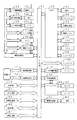
図5は、図3および図4に示した電子カメラ100の内部の電気構成例を示すブロック図であって、各構成要素は各種情報データおよび制御データを伝送するためのデータ/制御バス51を介して互いに接続されている。
各構成要素は大きく以下の5つのブロックに分類される。画像データの撮影動作を実行する撮影制御回路60を中心とするブロック、電子カメラ100の近傍にある電子機器との間で無線通信(ブルーツース等)により交信を行う無線通信回路71と無線携帯電話回線を用いて外部とデータの送受信を行う無線電話回路72を中心とするブロック、画像ファイルを記憶・保存するメモリカード104のブロック、画像データおよびその関連情報の表示を実行する画面制御回路92を中心とするブロック、操作キー65等のユーザーインターフェースと各制御回路に対する統括制御を行うCPU50を中心とするブロックである。
【0016】
CPU50(中央処理ユニット)は電子カメラ100全体の制御を行う手段であって、操作キー65、タッチタブレット66、各種検出回路70、電源スイッチ17、タイマ74、測光回路13、GPS回路61、姿勢検出回路62からの入力情報に応じて撮影制御回路60、無線通信回路71、無線電話回路72、画面制御回路92、電源制御回路64への各種指示を行う。
【0017】
録音回路80はCPU50の制御に基づき、撮影時に被写体の発する音声や撮影後に撮影者が発するメモ用の音声を音声データとして録音するとともに、音声データは画像データとともに画像ファイルに格納される。音声再生回路81はCPU50の制御に基づき、画像データ再生時に画像データとともに画像ファイルに格納されている音声データを再生したり、その他の音声データを再生する。
【0018】
測光回路13は被写体の輝度を測定し、その測定結果である測光データをCPU50に出力する。CPU50は測光データに応じて、CCD55の露光時間、感度をCCD駆動回路56により設定するとともに、該設定データに応じて撮影制御回路60を介し絞り53の絞り値を絞り制御回路54により制御する。
【0019】
CPU50は撮影モードではレリーズボタン15の操作に応じて撮影制御回路60を介し撮影動作を制御する。またCPU50は測光データに基づき被写体が暗い場合には、撮影時にストロボ駆動回路73を介しストロボ12を発光させる。
【0020】
GPS回路61(グローバルポジショニングシステム回路)は、地球の周りを周回している複数の衛星からの情報を用いて電子カメラ100の位置情報を検出し、画像撮影時に撮影位置情報をCPU50に供給する。姿勢検出回路62は、電子カメラ100の姿勢を検出するために周知の姿勢センサ(ジャイロセンサ、方位センサ)などから構成され、カメラの姿勢情報を検出し、画像撮影時に撮影姿勢情報をCPU50に供給する。
【0021】
タイマ74は時計回路を内蔵し、現在の日時に対応する日時情報を検出し、撮影時に撮影日時情報をCPU50に供給する。CPU50は、ROM67(リードオンリメモリ)に記憶されている制御プログラムに従い各部を制御する。EEPROM68(電気的消去書き込み可能ROM)は不揮発性のメモリであって、電子カメラ100の動作に必要な設定情報等を記憶している。CPU50は、電源スイッチ17の操作状態を検知して、電源制御回路64を介して電源63の制御を行う。
【0022】
撮影制御回路60は、レンズ駆動回路52により撮影レンズ10のフォーカシング、ズーミングを行い、絞り制御回路54により絞り53を制御してCCD55の露光量をコントロールし、CCD駆動回路56によりCCD55の動作を制御する。被写体からの光束は撮影レンズ10により光量調節のための絞り53を介し、CCD55上に被写体像として形成され、この被写体像はCCD55により撮像される。複数の画素を備えたCCD55(チャージカップルドデバイス)は被写体像を撮像するための電荷蓄積型イメージセンサーであり、CCD55上に形成された被写体像の強度に応じた電気的な画像信号をCCD駆動回路56により供給される駆動パルスに応じてアナログ処理部57に出力する。なおCCD55の有効画面サイズと撮影レンズ10の焦点距離によって決まる画角内に入る被写界が、撮影画面内に画像データとして撮影されることになる。
【0023】
撮影制御回路60は上述の動作を繰り返すとともに、画面制御回路92は撮影バッファメモリ59に順次格納されるデジタルデータをデータ/制御バス51を介して読み出してフレームメモリ69に一旦格納し、該デジタルデータを表示用画像データに変換してフレームメモリ69に再格納し、該表示用画像データを左画面21に表示させるという動作を繰り返す。また画面制御回路92は必要に応じてテキスト表示情報をCPU50から入手し、表示用テキストデータに変換してフレームメモリ69に格納し、該表示用テキストデータを左画面21、右画面22に表示させる。このようにして撮影モードにおいては、左画面21にCCD50により撮像されている画像がリアルタイムに表示されるので、このスルー画面をモニター画面として使用して撮影のための構図設定を行うことが可能になる。
【0024】
撮影制御回路60は撮影バッファメモリ59に格納したデジタルデータの高周波成分の度合い解析して撮影レンズ10の焦点調節状態を検出し、検出結果に応じてレンズ駆動回路52により撮影レンズ10の焦点調節を行う。
撮影時に撮影制御回路60はCPU50から撮影指示を受けると、CCD駆動回路56を介してCCD55により被写体像を撮像させ、撮像により生成した画像信号をアナログ処理部57、A/D変換回路58を介して撮影バッファメモリ59にデジタルデータ(生データ)として一旦格納する。撮影制御回路60は撮影バッファメモリ59に一旦格納したデジタルデータを所定の記録フォーマット(JPEGなど)に変換または圧縮して画像データを形成し、該画像データを撮影バッファメモリ59に再格納する。
【0025】
CPU50は無線通信回路71により被写体の所持している携帯電話等の電子機器と交信し、被写体に関する関連情報を収集するとともに、電子機器の位置情報を入手する。またCPU50は、GPS回路61から撮影位置情報と、姿勢検出回路62から撮影姿勢情報と、撮影制御回路60から撮影レンズ10の焦点距離情報を入手し、前記電子機器の位置情報と撮影位置情報と撮影姿勢情報と焦点距離情報に基づき後述する方法で画面内の被写体の位置を示す画面内位置情報を演算する。CPU50は、前記画像データと被写体に関する関連情報と被写体の画面内位置情報を画像ファイルとしてメモリカード104に格納する。
【0026】
再生モードにおいては、画面制御回路92はメモリカード104からCPU50に指示された画像ファイルを読み出してフレームメモリ69に一旦格納し、該画像データを表示用画像データに変換してフレームメモリ69に再格納し、該表示用画像データを左画面21に表示するとともに、CPU50の指示に従い、再生モードの説明等のテキストデータをフレームメモリ69に格納し、該テキストデータを右画面22に表示する。再生モードにおいて無線電話回路72はCPU50から送信指示を受けると、指定された画像ファイルをメモリカード104から読み出して、該画像ファイルを外部に無線送信する。
【0027】
情報表示モードにおいては、まずCPU50は再生モードと同じように画面制御回路92により所定の画像データを左画面21に再生表示させるとともに、被写体の画面内位置情報に応じた位置に情報アイコンをスーパーインポーズ表示させる。また説明用のテキストデータを右画面22に表示させる。CPU50は情報表示モードにおいて前記情報アイコンがタッチタブレット66により選択されると、その画面内位置情報に関連付けられた被写体関連情報に基づき無線電話回路72によりインターネット上の情報源(ホームページなど)にアクセスし、左画面21にそのホームページの画面などを表示し、右画面22には操作説明画面を表示する。
【0028】
図6はメモリカード104内に格納される画像ファイルのデータ構成を示す。図6に示すようにメモリカード104には複数の画像ファイルが保存される。各画像ファイルは画像データと付加情報データから構成される。付加情報データは、撮影時の各種設定を示す撮影情報データ(図7)、撮影を行った日時を示す日時情報データ、撮影を行った位置を示す位置情報データ、撮影を行った時のカメラの姿勢を示す姿勢情報データ、撮影時または撮影後に録音した音声情報データ、撮影時または撮影後に入力された撮影に関する一般的な情報を示す一般情報データ(図8)、撮影時または撮影後に入力された被写体に関連する情報を示す被写体情報データから構成される。
【0029】
被写体情報データは、撮影された画面に移っている被写体(人物、建物、風景など)の関連情報から構成される。例えば被写体が人物である場合にはその人の個人情報データ(図9)と被写体が建物などの場合にはその建物に関する一般情報データとから構成される。
【0030】
図7は撮影情報データの構成を示す図であって、撮影時の撮影レンズの設定やカメラの設定に関する設定情報から構成される。
図8は一般情報データの構成を示す図であって、各情報に対応したその情報のインターネットでのアクセスデータ(ホームページアドレスなど)とその情報コンテンツの内容を表すデータとその情報の送信元の位置情報データから構成される。
【0031】
図9は個人情報データの構成を示す図であって、該個人情報が画面内のどの被写体に対応しているのかを示す画面内位置情報、該個人情報の送信元の電子機器の位置情報、その個人のインターネットアクセス情報データ(ホームページのURL等)、Eメールアドレス、個人の氏名、生年月日、使用言語、身体的データ(視力、視度、利き手)、嗜好(色など)、その他のデータから構成される。
【0032】
図10は本発明による電子カメラ100の実施形態の状態遷移図である。電子カメラの動作モードには撮影モード、再生モード、情報表示モードの3つのモードがあり、3つの操作ボタン(撮影モードボタン25、再生モードボタン26、情報表示モードボタン27)の操作により、各モード間を移行する。電源をONすると、まず撮影モードに移行する。撮影モードでは撮影動作、無線交信動作、画像ファイルの作成・記憶動作を実行する。再生モードでは画像ファイルの再生動作と画像ファイルの外部への送信動作を行う。情報表示モードでは画像データに対応した付加情報データに基づいてインターネットにアクセスなどして、画像データに関連する情報を収集して表示する。
【0033】
図11は上記実施形態における電子カメラ100(CPU50)の動作のメインフローチャートである。まずS10により電源スイッチ17を操作すると電源がONとなり、S20で撮影モードサブルーチンを実行し撮影可能状態になる。撮影モード中にレリーズボタン16を操作すると、S30のレリーズ割込み処理サブルーチンが実行され、撮影動作が行われる。また撮影と同時にS30のレリーズ割込み処理サブルーチンからS40の無線割込みサブルーチンが呼び出され、電子カメラの周囲に存在している電子機器と無線交信を行い、被写体情報データや一般情報データを収集する。収集された被写体情報データ、一般情報データは撮影情報データとともに付加情報データとして構成され、画像データといっしょに画像ファイルとしてメモリカード104に格納される。
【0034】
また各動作モードにおいて3つの操作ボタン(撮影モードボタン25、再生モードボタン26、情報表示モードボタン27)を操作すると、S50のモード切換割込み処理が起動し、操作ボタンの種類に応じて各モードへの切換が行われる。
【0035】
S60の再生モードにおいては、メモリカード104に保存された画像ファイルを読み出し、画像データを表示画面に再生表示するとともに、送信ボタン28を操作すると、S70の送信割込み処理サブルーチンが実行され、再生モードで再生されている画像データを含む画像ファイルが外部に送信される。
【0036】
S80の情報表示モードにおいては、後述するようにまず画像データを表示画面に再生表示するとともに、表示画面上でタッチタブレット66によりユーザに指定された位置に対応する画面内位置情報を有する被写体情報そのものまたは該被写体情報に含まれるインターネットアクセス情報に基づいてインターネットにアクセスして収集した情報を表示画面に表示する。
【0037】
図12は撮影モードサブルーチンの詳細フローチャートであって、S20で起動すると、S201の処理を繰り返す。S201ではユーザが設定した撮影設定条件に基づき順次CCD55により生成される画像データを図13に示すように左画面21に表示し、そのときの撮影設定条件を右画面22にテキスト表示する図14はレリーズ割込み処理サブルーチンの詳細フローチャートであって、S30で起動すると、S301で撮影モードであるかチェックし、撮影モードでない場合はS305でリターンする。撮影モードの場合は、S302でユーザに設定された撮影設定条件で撮像動作を実行し、画像データを生成し、次に後述するS40の無線交信処理サブルーチンを実行し、付加情報データを生成する。S303では画像データと付加情報データをまとめて画像ファイルを生成し、メモリカード104に保存する。S304では画像データを所定時間だけ画面に表示して、S305でリターンする。なお画像データは所定の撮影画面サイズを有しており、撮影された被写体は撮影構図に応じて、この撮影画面内のどこかの位置に配置されていることになる。
【0038】
図15は無線交信処理サブルーチンの詳細フローチャートであって、S40で起動すると、S401で撮影モードであるかチェックし、撮影モードでない場合はS408でリターンする。撮影モードの場合は、S402で無線通信手段71により、電子カメラ100の周囲にある電子機器(被写体となる人物が所持している携帯電話や史跡近傍に固定設定されており該史跡の観光情報を無線交信により送信可能な電子観光ガイド装置)に対して無線交信を試みる。その際撮影レンズの焦点距離に応じて、無線交信の際の信号送信出力を変更する。例えば焦点距離が長いほど被写体が遠距離に存在すると推測されるので、信号送信出力レベルを大きくする。S403で交信が成立しなかった場合はS408でリターンする。交信が成立した場合は、S404で交信が成立した交信相手の電子機器より電子機器の位置情報データと被写体情報データ(または一般情報データ)を無線交信により取得する。S405では電子カメラ100自身の位置情報をGPS回路61から受け取るとともに、電子カメラ100自身の姿勢情報を姿勢検出回路62から受け取り、前記電子機器の位置情報と電子カメラ100の位置情報と電子カメラ100の姿勢情報から後述するように、電子カメラ100に対する被写体(電子機器)の位置を求める。S407では撮影レンズ10の焦点距離情報を撮影制御回路60から受け取り、後述するように該焦点距離情報と撮像素子の有効画面サイズから撮影時の画角を演算するとともに、前記電子カメラ100に対する被写体の位置情報に基づき、撮影した画面内での被写体の位置(画面内位置情報データ)を生成し、S408でリターンする。
【0039】
図16は上記レリーズ割込み処理と無線交信処理の際の電子カメラと電子機器との間で行われる無線交信動作を説明するためのシーケンス図であって、まず電子カメラ100側でレリーズ操作されると、それに応じて撮影動作が行われ、次に電子カメラ100側から周囲にある電子機器に対して▲1▼交信要求の無線交信が試みられる。▲1▼交信要求では送信元を示す電子カメラ100の識別情報も送信される。
【0040】
この▲1▼交信要求を受信した電子機器は、これに応答してして電子カメラ100に対し▲2▼応答を行い、送信元の電子機器の識別情報と送信先の電子カメラ識別情報を送信する。
▲2▼応答を受信した電子カメラ100は、電子機器の識別情報に基づいて交信相手を確認するとともに、交信相手の電子機器を特定して関連情報を要求するために、▲3▼情報要求を送信する。▲3▼情報要求では、送信先の電子機器の識別情報、送信元の電子カメラ100の識別情報、要求する情報の内容などが電子機器側に送信される。
【0041】
▲3▼情報要求に含まれる電子機器の識別情報に対応する電子機器は、要求された関連情報(位置情報、アクセス情報など)を電子カメラに▲4▼情報送信する。▲4▼情報送信には、送信先の電子カメラ100の識別情報、送信元を示す電子機器の識別情報、関連情報が含まれる。
【0042】
電子カメラ100は電子機器からの▲4▼情報送信をうけとる。電子カメラ100は▲1▼交信要求に応答したすべての電子機器に対して順次▲3▼情報要求を行うとともに、該電子機器からの▲4▼情報送信を受け取ると、無線交信を終了し、画像ファイルを生成して、該画像ファイルをメモリカード104に保存する。
【0043】
図17と図18は被写体の画面内位置情報データの求め方の説明図である。被写体位置情報データと撮影位置情報データは所定の基準原点を中心とした3次元座標系での位置座標として与えられる。まず図17に示すように前記基準座標系の原点を電子カメラ100の中心点3(撮影位置)に平行移動した座標系(軸P:カメラ光軸方向、軸Q:カメラ横方向、軸R:カメラ縦方向)に変換し、変換後の被写体203の位置座標を求める。
【0044】
また図18に示すように撮影レンズの焦点距離情報とCCD20の有効画面サイズから撮影光軸方向(P軸)に画角5(一点鎖線で示す)が算出される。次に原点3と被写体位置203を結んだ直線の方向算出する。画角5と直線4の方向を比較することにより、被写体が画面内に入っているか否かや図19に示すように被写体の画面内での位置(画面内位置情報データ)を算出することができる。
【0045】
図20は操作ボタン(撮影モードボタン25、再生モードボタン26、情報表示モードボタン27)の操作により起動するモード切換割込み処理サブルーチンの詳細フローチャートであって、S50で起動すると、S501で操作されたボタンが撮影モードボタン25であるかチェックし、撮影モードボタン25である場合にはS20の撮影モードサブルーチンに移行する。撮影モードボタン25でない場合は、S501で操作されたボタンが再生モードボタン26であるかチェックし、再生モードボタン26である場合にはS60の再生モードサブルーチンに移行する。再生モードボタン26でない場合は、S80の情報表示モードサブルーチンに移行する。
【0046】
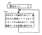
図21は再生モードサブルーチンの詳細フローチャートであって、S60で起動すると、S601の処理を繰り返す。S601では方向ボタン23,24の操作に応じてメモリカード104に格納された画像ファイル中の画像データを選択して読み出し、図22に示すように左画面21に再生表示するとともに、右画面22に操作方法の説明を表示する。
【0047】
図23は送信割込み処理サブルーチンの詳細フローチャートであって、S70で起動すると、S701で再生モードであるかチェックし、再生モードでない場合はS703でリターンする。再生モードの場合は、S702で図24に示すように右画面22に送信先を表示する。送信先には現在左画面21に再生表示されている画面内の被写体への送信先も含まれる。ユーザにより送信先が指定されると、現在左画面21に再生表示されている画像データを含む画像ファイルをメモリカード104から読み出し、該画像ファイルをユーザにより指定された送信先へ無線電話回路72により送信し、S703でリターンする。
【0048】
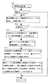
図25は情報表示モードサブルーチンの詳細フローチャートであって、S80で起動すると、まずS801で情報表示モードのホーム画面を表示する。ホーム画面では図22に示すように左画面21に画像データを表示する。再生モードから情報表示モードに移行した場合には、再生モードで左画面21に再生表示されていた画像データをそのまま表示し、撮影モードから情報表示モードに移行した場合には最後に撮影された画像ファイルの画像データが表示される。また左画面21には画像データに重畳(スーパーインポーズ)して、付加情報データに含まれる画面内位置情報データに応じた位置に被写体情報を示すアイコン82、83が表示されるとともに、撮影位置情報データに応じて地図を表示するためのアイコン85と撮影日時情報データに応じて撮影日のニュースを表示するためのアイコン84と一般情報を表示するためのアイコン86が表示される。右画面22には左画面21に対する操作説明が表示される。
【0049】
S802でユーザが左画面21の所望のアイコンをタッチするとタッチタブレット66によりユーザによりタッチされた画面上の位置が検出され、該タッチ位置に応じて以下のステップに分岐する。
図26においてアイコン85がタッチされた場合はS803に分岐し、無線電話回路72経由でインターネット上の地図データベースにアクセスし、ホーム画面に表示された画像データの撮影位置情報に応じて撮影位置を含む地図データを地図データベースからダウンロードして図27に示すように左画面21に表示する。左画面21には縮小アイコン87と拡大アイコン88が地図画面に重畳されて表示され、ユーザがそれらをタッチすると、タッチされたアイコン応じて地図画面が縮小または拡大される。右画面22にはホーム画面に表示されていた画像データがサムネイル画像(縮小画像)で表示され、このサムネイル画像部分をユーザがタッチするとS801のホーム画面に戻る。
【0050】
図26においてアイコン84がタッチされた場合はS804に分岐し、無線電話回路72経由でインターネット上のニュースデータベースにアクセスし、ホーム画面に表示された画像データの撮影日時情報に応じて撮影日時に発生したニュースデータをニュースデータベースからダウンロードして図28に示すように左画面21に表示する。左画面21にはニュースリストと詳細アイコン89が表示され、ユーザが詳細アイコンをタッチすると、タッチされたニュースの詳細が更に左画面21に表示される。右画面22にはホーム画面に表示されていた画像データがサムネイル画像(縮小画像)で表示され、このサムネイル画像部分をユーザがタッチするとS801のホーム画面に戻る。
【0051】
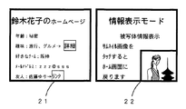
図26においてアイコン82またはアイコン83がタッチされた場合はS805に分岐し、アイコンが示す被写体情報に含まれるインターネットアクセス情報データに応じて無線電話回路72経由でインターネット上の被写体に関連する詳細な情報を蓄積した情報源(ホームページやデータベース)にアクセスし、そのホームページのトップ画面を表示する。例えばアイコン82をタッチした場合には、図29に示すように被写体となっている人物のホームページのトップ画面が左画面21に表示され、タッチタブレット66の操作により更に下層の画面を表示したりや別のホームページにリンクしたりすることができる。またアイコン83をタッチした場合には、図30に示すように、画面に写っている歴史的建造物の解説画面が左画面21に表示され、タッチタブレット66の操作により更に詳細な解説や画像を左画面21に表示させることができる。右画面22にはホーム画面に表示されていた画像データがサムネイル画像(縮小画像)で表示され、このサムネイル画像部分をユーザがタッチするとS801のホーム画面に戻る。
【0052】
図31は電子カメラ内の無線通信回路71の構成を示す説明図であって、無線通信回路71は電磁シールドフィルム79によりカメラ背面(撮影光軸方向と反対の方向=撮影者の方向)と下面と上面と左右の側面を囲まれている。したがって無線通信回路71はカメラの撮影方向に位置する被写体の所持している携帯機器160との交信がし易く、確実に被写体情報を収集できるとともに、撮影光軸方向にない被写体以外が所持している携帯機器とは交信がし辛くなっているので、被写体以外の無駄な情報はなるべく収集しないようにできる。図32は無線通信回路71の交信の指向性を示した図であり、電子カメラ100の前面方向(光軸40の方向)に強い指向性を持ち、背面方向の指向性は弱い。
【0053】
上記のように図31に示す構成により無線通信回路71をカメラの撮影方向に強い指向性を持たせることにより、被写体の所持する電子機器と交信できる確率を高めることができる。なお指向性の調整は電磁シールドフィルム以外に、アンテナの構成により調整することも可能である。
【0054】
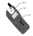
図16の無線交信処理では撮影時に電子カメラ100が周囲の電子機器と交信して被写体情報を収集しているが、撮影前後に被写体側の電子機器側から撮影を行った電子カメラに被写体情報を送信するようにしてもよい。例えば図33に示すように被写体が所持する携帯電話160には、UIMカード等の装着によって該携帯電話160を所持しているユーザの個人情報が記憶保存されている。携帯電話160は表示画面161と操作ボタン162を備えている。被写体となる人物がその人の個人情報を電子カメラ側に送信する場合は、まず携帯電話160の操作ボタン162を操作すると携帯電話160は個人情報送信モードとなり、電子カメラに被写体情報を送信する。送信が終了すると図34に表示画面161に送信先の電子カメラと送信終了の旨を表示する。このようにすれば、被写体側で個人情報の送信の可否を決定できるので、不用意に個人情報が流出することを防止できる。
【0055】
図18に示す被写体の画面内における位置の検出においては、GPSで検出した電子カメラの位置情報と電子機器の位置情報を利用しているが、これ以外の方法で被写体の画面内位置を検出してもよい。図35は無線通信回路71の交信用アンテナとして使用する狭指向性無線アンテナ75(その指向性43は図36に示すように一方向42に極めて強い指向性を持っている)を用いて被写体の撮影画面内における位置を検出する場合の例である。なおこのような小型の指向性アンテナの詳細な構成については特開2000−278037号公報などに開示されている。
【0056】
電子カメラ100には狭指向性無線アンテナ75と該狭指向性無線アンテナ75の方向を機械的に走査駆動して変更する駆動部76が内蔵されている。撮影時の無線交信処理の際、CPU50は駆動部76により該狭指向性無線アンテナ75が撮影画面内を走査するように駆動しながら、無線通信回路71により画面内の被写体と交信して被写体情報データを収集する。これにより狭指向性無線アンテナ75の走査位置(=画面内位置情報データ)と被写体情報データとを対応付けることができる。
【0057】
図37は上記狭指向性無線アンテナ75を用いた無線交信処理サブルーチンの詳細フローチャートであり、S40で起動すると、S411で撮影モードであるかチェックし、撮影モードでない場合はS419でリターンする。撮影モードの場合は、S412で上記狭指向性無線アンテナ75の走査位置を初期化する。なお画面サイズは撮影レンズの焦点距離情報とCCDの有効画面サイズにより決定される。S413で無線通信手段71により、電子カメラ100の周囲にある電子機器(被写体となる人物が所持している携帯電話や史跡近傍に固定設定されており該史跡の観光情報を無線交信により送信可能な電子観光ガイド装置)に対して無線交信を試みる。S414で交信が成立しなかった場合はS417に進む。交信が成立した場合は、S415で交信が成立した交信相手の電子機器より被写体情報データを無線交信により取得する。S416では被写体情報データの画面内位置情報を狭指向性無線アンテナ75の走査位置情報とする。S417では狭指向性無線アンテナ75の走査位置を更新する。S418では狭指向性無線アンテナ75の走査位置が終了位置かどうかチェックし、終了位置でない場合はS413に戻り上記動作を繰り返すとともに、終了位置であった場合はS419でリターンする。
【0058】
図38は情報表示モードにおけるホーム画面の表示例であって、左画面21には図26と相違してアイコンが表示されない。ユーザが左画面に表示されている人物や建物をタッチするとタッチタブレット66にてタッチ位置が検出され、タッチ位置に応じた画面内位置情報データを持つ被写体情報が図39に示すように右画面22に表示される。また被写体情報に対応した左画面21上の被写体の位置に矢印マーク44が表示される。このようにすれば左画面21に再生表示される画像データを邪魔なアイコンなしで鑑賞できるとともに、左画面21で興味が沸いた被写体をタッチすれば、画像データを左画面21に表示したまま、右画面22で被写体情報を閲覧することができるとともに、被写体情報と画像上の被写体との関係を確認することができる。またこのようにすれば情報表示モードと再生モードを統合して、再生モードから直接被写体情報を表示することも可能になる。
【0059】
また図40に示すように画像解析により再生表示された被写体画像の輪郭を抽出し、該輪郭の近傍の領域(図40で人物45の近傍の領域46)をユーザがタッチした場合には該領域46に含まれる画面内位置情報データに対応する被写体情報を左画面21に表示するようにしてもよい。このようにすれば被写体情報を電子カメラに送信した電子機器があった位置以外の例えば顔部分をタッチした場合でも該人物の被写体情報を表示することができる。
【0060】
図41は図25で示した情報表示モードサブルーチンのS801とS802の間に新しい処理を追加した場合の詳細フローチャートである。この新しい処理は、被写体情報を持たない画像ファイルに被写体情報を持つ類似した画像ファイルの被写体情報を移植する処理である。
【0061】
S801でホーム画面を表示した後、S811で左画面21に再生表示された画像データの画像解析を実行して主要被写体(人物、建物など画面中で比較的大きな面積を占める被写体)を識別するとともに、S812で該主要被写体の領域に画面内位置情報データを持つ被写体情報が存在するかチェックし、存在する場合にはS802に進む。存在しない場合はS813にて再生表示されている画像データの撮影日時データと同じ撮影日時データを持つ画像ファイルをメモリカード104内で探索して抽出する。次に該画像ファイルの画像データを画像解析して現在再生表示されている画像データ中の主要被写体と類似な被写体を持つ画像データを更に抽出する。次に抽出された画像データの中の類似被写体に画面内位置情報が付いているかチェックし、付いていた場合には該被写体情報を現在再生表示されている画像データの主要被写体の被写体情報として、画像解析により特定された主要被写体の画面内の位置に応じた画面内位置情報を付けて、現在再生表示されている画像データの画像ファイルを更新する。
【0062】
S814では現在再生表示されている画像データを含む画像ファイルから撮影位置情報データ、撮影姿勢情報データ、焦点距離情報データを読み出し、該情報データに応じてインターネット上の地図データベースとS813の画像解析結果により主要被写体の特定を行う。例えば山中湖付近から南方向に向かって撮影した画面に三角形の山らしき物体が写っている場合には富士山であると特定する。主要被写体が特定された場合には、該主要被写体名をキーワードにインターネットで検索し、その主要被写体の解説が載っているホームページのアクセス情報を取得し、画像解析により判別した主要被写体の画面内の位置に応じた画面内位置情報を付けて、現在再生表示されている画像データの画像ファイルを更新する。
【0063】
上記のように被写体情報を持たない画像ファイルに他の画像ファイルやインターネットから被写体情報を移植した後にS802へ進む。このようにすれば撮影時に被写体情報を取得できなかった場合(風景画像などで電子カメラ近傍に被写体情報を無線で供給する観光ガイド装置なかった場合など)でも、画像データを情報表示モードで再生した場合に、被写体に関する情報を表示することができる。なおS813で探索する画像ファイルの範囲は同一の撮影日時に限定されることはない。例えば被写体情報を持たない画像ファイルの前後に撮影した所定数の画像ファイルの中から探索するようにしてもよい。またS814でカメラが撮影位置情報データ、撮影姿勢情報データ、焦点距離情報データから自動的に被写体を特定し、特定した被写体の情報をインターネットからダウンロードしているが、ユーザが画像データを閲覧して被写体を特定し、特定した被写体の情報を入力またはインターネットからダウンロードし、該情報を画面上の被写体位置に貼り付けるようにして画像ファイルを更新するようにしてもよい。
【0064】
図42は本発明を適用した電子カメラと該電子カメラを利用した電子画像通信システムの別の概念図である。図2の電子画像通信システムにおいては、電子カメラ100とユーザの所持する携帯電話160が近距離無線通信を行うことにより、携帯電話160に装着されたUIMカード170に記憶された個人情報データが電子カメラ100に読み込まれるようになっているが、図42の電子画像通信システムでは個人情報データを記憶した無線タグ(非接触ICカード)が非接触無線読み込み部を内蔵した電子カメラ100に近接すると、個人情報データが無線タグから電子カメラ100に自動的に読み込まれる。
【0065】
上記のように図42に示す電子画像通信システムにおいては、被写体は電源不要な小型の無線タグ(非接触ICカード)を保持しているだけで、電子カメラ100と交信することができる。
上記実施形態(図1、図11)においては、画像データの撮影時に電子カメラと被写体の所持している携帯機器の間で無線交信が行われ、電子カメラに被写体情報(位置情報を含む)が自動的に転送されるので、被写体情報を取得するための特別な操作が不要になるとともに、画像データを撮影した時点での被写体の位置情報を取得できるので、該位置情報を使って画面内位置情報データを求める場合に、画面上の実際の位置に正確に対応した位置を求めることができる。なお被写体の位置情報の取得タイミングは、被写体撮影タイミングの近傍のタイミング(1秒前後以内が望ましい)であれば、画面上の実際の位置に正確に対応した位置を求めることができる。
【0066】
上記実施形態(図1、図11)においては、画像データを再生表示して閲覧している際に興味を持った画面中に写っている被写体に関連する情報を、画面内位置情報に応じて画面に表示されているアイコンや被写体をタッチするのみで簡便かつ迅速に閲覧することができる。
【0067】
上記実施形態(図1、図15)においては、無線交信により被写体より被写体情報を取得する際に近距離無線を用いているので、電子カメラの近傍に存在する被写体と交信できる確率を高めるとともに、電子カメラから遠距離にある被写体とは無関係な電子機器を排除できる。また撮影レンズの焦点距離に応じて無線交信の際の信号送信出力レベルを調整しているので、被写体と確実に無線交信を成立させることができるとともに、被写体以外とは無線交信が成立する可能性を少なくすることができる。
【0068】
上記実施形態(図23)においては、再生モードで再生表示された画像データを該画像データの撮影時に取得された被写体情報データに含まれる転送先に送信することができるので、旅先などで偶然出会った人を撮影した際に相手の住所やeメールアドレスなどを聞いて控えておく必要なく、簡単に被写体となった人に画像データを送信することができる。特に大勢の人の集合写真を撮った場合などに、画像データの送付の手間が省けて便利である。
【0069】
上記実施形態(図27など)においては、情報表示モードでユーザに指定された被写体情報を画面に表示する場合、元になる被写体が写った画像データを同時に表示(サムネイル画像)しているので、画像データと被写体の関連を直感的に把握することができるとともに、画像データをタッチタブレット66により指定することによりホーム画面にすぐ戻ることができるので、画像データを中心とした被写体情報の閲覧を簡便に行うできる。
【0070】
上記実施形態(図31、図32)においては、電磁シールドシートなどにより無線通信回路71の無線通信の指向性を電子装置本体に対して被写体が存在する確率の高い方向に制限しているので、無線交信により被写体情報を取得する場合に、被写体と確実に無線交信を成立させることができるとともに、被写体以外とは無線交信が成立する可能性を少なくすることができる。
【0071】
上記実施形態(図33、図34)においては、被写体側の起動により被写体情報が電子カメラに送信されるようにしたので、必要に応じて個人情報などがむやみに外部に流出することを防止できる。
上記実施形態(図37)においては、狭指向性無線アンテナを用いて画面内を走査し、被写体の画面内位置情報を収集するようにしたので、被写体側の電子機器やGPS等の特別な測位手段を備える必要がなく、低コストにシステムを構成できる。
【0072】
上記実施形態(図41)においては、画像解析により被写体の画面内位置情報を検出するとともに、類似画像ファイルから被写体情報をコピーするので、撮影時に被写体情報を取れなかった被写体についても、閲覧時には被写体情報を参照することが可能になる。また画像解析により被写体の画面内位置情報を検出するとともに、画像解析および位置情報などにより被写体を特定し、インターネットなどの情報源から特定された被写体に関する被写体情報を収集するので、撮影時に被写体情報を取れなかった被写体についても、閲覧時には被写体情報を参照することが可能になる。
【0073】
上記実施形態(図42)においては、電子カメラが非接触ICカード(無線タグ)の読み取り回路を備え、被写体が所持している非接触ICカード(無線タグ)から被写体情報を非接触で読み取るようにしているので、被写体は軽量で小型で電源不要な非接触ICカードを保持しているのみで一切の操作を必要としない。
(変形形態の説明)本発明は以上説明した実施形態に限定されることなく、種々の変形や変更が可能である。
【0074】
上記実施形態(図1)においては無線(電波)により電子カメラと被写体の保持する電子機器が交信を行うことで被写体情報の取得しているが、真の被写体以外の人が所持している電子機器とむやみに交信を成立させないために、平均的な受信性能を電子機器が備えていることを想定し、無線送信信号の出力レベルを所定値以内に限定して交信可能な距離範囲を制限しておくのが望ましい。電子カメラの使われ方や電子カメラと電子機器との間の電波遮蔽物の有無や電子機器の受信機の性能などを考慮して前記距離範囲は決定されるが、通常の撮影レンズの焦点距離においては10m程度以内がよい。
【0075】
上記実施形態(図1)においては無線通信回路は例えばブルーツースのような近距離無線により交信を行っているとしたが、ブルーツース以外でも無線LAN(IEEE802.11)や赤外線通信(IrDA)により近距離無線交信を行うようにしてもよいし、複数の近距離無線方式を同時に使用して交信を行っても良い。このようにすれば被写体が保持している電子機器がどのような近距離無線機能を持っていっても、電子カメラ側と無線交信を行うことができる。
【0076】
上記実施形態(図1)においては無線(電波)により電子カメラと被写体の所持する電子機器が交信を行うことで被写体情報の転送を行っているが、これ以外の方法で非接触方式または接触方式で被写体情報の転送を行ってもいい。
上記実施形態(図5)においては撮影時に録音回路80により音声を録音することができるが、撮影時に狭指向性マイクを使用して画面内の一部に存在する被写体の音声を録音するとともに、該録音データを被写体の画面内位置情報と関連つけて画像ファイルに記憶するとともに、情報表示モードにおいて再生表示された画面においてその被写体がタッチタブレットなどにより指定された場合に該録音した音声を再生するようにしてもよい。また複数の狭指向性マイクを備え、画面内の複数の被写体に対して同時に録音し、情報表示モードにおいて再生表示された画面において各被写体がタッチタブレットなどにより指定された場合に各被写体に対応した音声を再生するようにしてもよい。
【0077】
また撮影時または撮影タイミングとは無関係に被写体の所持しているマイク付き電子機器や予め音声データで被写体に関する情報を記憶している電子機器から無線交信により被写体の発する音声や被写体に関連する解説などを被写体音声情報として電子カメラに送り、その被写体音声情報を画面内位置情報により撮影画面内の被写体の位置に関連付けて、被写体を撮影した画像データに付加して保存しておいてもよい。情報表示モードにおいて該画像データを再生して閲覧する際に、表示画面において各被写体がタッチタブレット等のポインティングデバイスにより指定された場合には、各被写体の位置に対応付けられて記憶されていた被写体音声情報を音声再生する。このようにすれば視覚情報だけでなく音声情報も利用して多角的に被写体の情報を閲覧者に提供することができる。
【0078】
上記実施形態(図5)においてはタッチタブレット66を左画面21および右画面22上の位置を指定するのに使用しているが、これ以外のポインティングデバイスでもかまわない。例えばトラックボールやマウスを画面位置指定手段として使用できる。また電子ファインダ(小型の画面表示手段により表示され画面を光学系により拡大してユーザに観察させるファインダ)を利用した場合には、ユーザの視線方向(視線位置、注視位置)を検出することにより、画面位置を指定することができる。またタッチタブレット66を使用する際には、ユーザの指以外に位置指定専用の部材(ペン)を用いることにより、より正確な位置を指定したり、画面を指で触れただけでむやみに被写体情報が表示されないようにしてもよい。
【0079】
上記実施形態(図9)においては無線(電波)により電子カメラと被写体の所持する電子機器が交信を行うことで被写体情報の転送を行っているが、電子カメラに被写体情報を送信した電子機器に電子カメラから被写体情報の受信通知を行い、被写体側の電子機器において被写体情報が転送された旨を表示してもいい。また電子機器は発音手段を用いて被写体情報が転送された旨を被写体となる人物に報知してもよい。
【0080】
このようにすれば、被写体側で被写体情報が転送された旨を認知できる。また音による報知を行うことにより電子機器が表示手段を備えていない場合でも、被写体情報が転送された旨を認知できるとともに、電子機器を被写体の衣服のポケットの中などに入れたままでも被写体となる人物はユーザは被写体情報が転送された旨を認知できる。
【0081】
上記実施形態(図11)においては、電子カメラにおいて撮影モード動作と再生モード動作と情報表示モード動作を行っているが、電子カメラで撮影を行って画像データを生成し、無線交信により被写体情報と画面内位置情報を収集して画像ファイルを作成し、この画像ファイルをオンラインまたはオフラインで電子カメラ以外の画像表示装置に転送し、該画像表示装置において再生モードおよび情報表示モードの動作を実行するようにしてもよい。
【0082】
上記実施形態(図11)においては、再生モードと情報表示モードを手動操作により切換えているが、再生モードで再生した表示画面においてユーザが画面内の所定位置にある被写体をタッチタブレットにより指定した場合に、該被写体に関連する被写体情報を表示するようにしてもよい。このようにすれば再生モードと情報表示モードを切換えるすることなく、画像データを閲覧中に興味がわいた時点にすぐその被写体に関する情報を見ることができる。
【0083】
上記実施形態(図11)の再生モードと情報表示モードにおいては、撮影時に録音回路80により録音した音声データを画像データ再生時に、音声再生回路81により再生するようにしてもよい。また撮影日時データに基づきインターネット上の音楽データベースからその当時流行していた音楽をダウンロードして、画像データ再生時にバックグラウンドミュージックとして自動的に音楽再生するようにしてもよい。このようにすれば視覚的と同時に聴覚的にも撮影当時のことを思い出し易くなり、画像閲覧を楽しむことができる。
【0084】
上記実施形態(図14)においては、電子カメラは撮影時に被写体と交信して収集した被写体情報について撮影者に通知していないが、撮影した画像データとともに収集した被写体情報のリストを表示するようにしてもよい。このようにすれば、撮影者は撮影時にどのような被写体情報が収集されたかを認知でき、不足している情報がある場合には必要に応じて更なる情報収集の策を講じることができる。
【0085】
上記実施形態(図15)においては、電子カメラは撮影時に被写体情報収集のために電子カメラの周囲にある電子機器と無線交信を試みるが、電子カメラの撮影者の所持している電子機器とは予め無線交信を行わないように設定しておいてもよい。また撮影時に撮影者の所持している電子機器と無線交信を行った場合には撮影情報データの一項目として撮影者情報として記録しておいてもよい。
【0086】
上記実施形態(図15)においては、電子カメラは撮影時に被写体情情報収集のために電子カメラの周囲にある電子機器と無線交信を試みるが、この時無線交信(電波、赤外線)の送信信号出力レベルを被写体距離に応じて変更(被写体距離が遠いほど出力レベルを大きくする)するようにしてもよい。被写体距離は周知の距離検出装置により検出された距離や手動で設定された撮影レンズの撮影距離を用いることができる。このようにすれば被写体が保持する電子機器と高い確率で交信ができるとともに、被写体以外が保持する電子機器と交信が成立する確率を少なくすることができる。
【0087】
上記実施形態(図16)においては、撮影時に電子カメラと被写体が保持している電子機器の間で無線交信が行われ、自動的に被写体情報が電子カメラに転送されるようになっているが、電子機器が電子カメラから▲1▼交信要求または▲3▼情報要求を受信した時に、電子機器が被写体に対して報知を行うとともに、被写体の指示にしたがってその後の交信を継続するか否かを切替えるようにしてもよい。このようにすれば、被写体は必要に応じて交信を拒否することができ、個人情報が必要以上に外部に流出することを防止できる。
【0088】
また電子機器が電子カメラから▲1▼交信要求または▲3▼情報要求を受信した時に、電子機器はその交信要求を送信してきた電子カメラの識別番号を予め電子機器に登録されている電子カメラの識別番号と比較し、登録されていない電子カメラの場合は、その後の交信を行わないようにしてもよい。このようにすれば個人情報の流出範囲を自動的にコントロールすることができる。
【0089】
上記実施形態(図16)においては、撮影時に電子カメラと被写体が保持している電子機器の間で無線交信が行われ、自動的に被写体情報が電子カメラに転送されるようになっているが、撮影時以外に電子カメラと被写体が保持している電子機器の間で無線交信が行われ、自動的に被写体情報が電子カメラに転送されるようにしてもよい。このようにすれば、同じ構図で何枚か撮影するような場合(露出ブラケット撮影など)には撮影の度に無線交信を行う必要がなく、一連の撮影終了がすばやくできるとともに、撮影終了後などに自動または手動による1回の無線交信で複数の画像データに対する被写体情報の収集ができる。
【0090】
上記実施形態(図16)においては、撮影時に常に電子カメラと被写体が保持している電子機器の間で無線交信が行われ、自動的に被写体情報が電子カメラに転送されるようになっているが、無線交信のために撮影動作に遅延が生じてしまうような場合には、被写体情報取得のための無線交信動作を禁止するようにしてもよい。例えば連続撮影(連写)を行う場合には、無線交信を自動的に禁止するようにすれば、無線交信動作のために連続撮影のコマ間が長くなってしまうことを防止できる。
【0091】
上記実施形態(図18)においては、被写体の画面内位置情報を電子カメラの姿勢情報とGPSによる電子カメラと電子機器の測位情報とにより算出しているが、これ以外の方法で被写体の画面内位置情報を検出してもよい。例えば電子カメラと被写体の保持する電子機器が赤外線を用いて交信する場合には、電子カメラ側に備えた2次元赤外線撮像素子で撮像した画像データから撮像素子上での受光位置を検出して電子機器の画面内の位置を特定するようにしてもよい。また画面内位置情報だけを電子機器の発する赤外線点光源の位置を2次元赤外線撮像素子で検出し、被写体情報の交信は無線通信(電波)を使用するようにしてもよい。その場合電子機器が無線交信を行うタイミングで上記赤外線点光源を点灯させる。
【0092】
上記実施形態(図25)においては、情報表示モードで画面上のユーザのタッチ位置に応じた被写体情報をインターネットにアクセスして表示しているが、必ずしもインターネットにアクセスする必要はなく、撮影時に収集した被写体情報で充分な場合は、該被写体情報のみを画面表示するようにしてもよい。このようにすれば被写体情報の表示の際、インターネットにアクセスする必要がないので、迅速に被写体情報を表示させることができ、閲覧の際に待たされるユーザのストレスを軽減することができる。
【0093】
上記実施形態(図26)においては、情報表示モードにおいて所定の撮影画面の大きさで撮影された画像データを、表示画面の大きさに一致させて再生表示させ、ユーザにより指定された表示画面上の位置に対応した被写体情報を表示画面に表示させているが、必ずしも撮影画面と表示画面の大きさを一致させる必要はなく、表示画面上で撮影画面を拡大または縮小して表示させるようにしてもよい。また画像データを変形、回転等を行って表示画面に表示させるようにしてもよい。このように撮影画面と表示画面が一致しない場合には、表示画面上で指定された位置を撮影画面上の位置に座標変換(拡大、縮小、シフト、回転など)し、変換された位置座標に基づき被写体情報を表示する。このようにすれば、撮影画面と表示画面の形状を合同にする必要がなくなり、種々の画像表示装置において情報表示モードの使用が可能になるとともに、被写体が近接して混在している場合には、表示画面を拡大してから所望の被写体を指定することができる。
【0094】
上記実施形態(図27)においては、電子カメラは2つの表示画面を備え、情報表示モードにおいて一方の画面の被写体情報を表示するとともに、もう一方の画面に被写体を含む画像データを表示(サムネイル画像)しているが、電子カメラが1つの画面しか備えていない場合は、被写体情報を全画面で表示するとともに、その一部に被写体を含む画像データを重畳表示してもよい。このようにすれば、表示画面が1つしかない場合でも被写体情報とその元になる画像データを同時に閲覧できるので、被写体情報と画像データの関連を直感的に捉えることができる。
【0095】
【発明の効果】
以上説明したように、本発明による電子カメラおよび画像表示装置および画像表示方法においては、画面内における被写体の位置に関連付けられた前記被写体の関連情報を電子画像データに付加して記憶しておくとともに、前記電子画像データを再生表示した際には、画面内の位置に応じて前記被写体の関連情報を表示するようにしたので、電子画像データを再生表示して閲覧している際に興味を持った画面中に写っている被写体に関連する情報を、電子画像データの再生表示と連携して簡便かつ迅速に閲覧できる。
【図面の簡単な説明】
【図1】本発明の実施形態の概念を示す説明図である。
【図2】本発明の実施形態のシステム構成を示す説明図である。
【図3】本発明による電子カメラの外観図(正面視)である。
【図4】本発明による電子カメラの外観図(背面視)である。
【図5】本発明による電子カメラの電気構成を示すブロック図である。
【図6】メモリ内のデータの構成図である。
【図7】撮影情報データの構成図である。
【図8】一般情報データの構成図である。
【図9】個人情報データの構成図である。
【図10】本発明による電子カメラの状態遷移図である。
【図11】メインプログラムのフローチャートである。
【図12】サブルーチンのフローチャートである。
【図13】画面の表示例である。
【図14】サブルーチンのフローチャートである。
【図15】サブルーチンのフローチャートである。
【図16】交信シーケンスの説明図である。
【図17】位置情報検出の説明図である。
【図18】位置情報検出の説明図である。
【図19】位置情報検出の説明図である。
【図20】サブルーチンのフローチャートである。
【図21】サブルーチンのフローチャートである。
【図22】画面の表示例である。
【図23】サブルーチンのフローチャートである。
【図24】画面の表示例である。
【図25】サブルーチンのフローチャートである。
【図26】画面の表示例である。
【図27】画面の表示例である。
【図28】画面の表示例である。
【図29】画面の表示例である。
【図30】画面の表示例である。
【図31】無線回路の構成の説明図である。
【図32】交信指向性の説明図である。
【図33】携帯電話の外観図である。
【図34】画面の表示例である。
【図35】画面内位置情報検出の説明図である。
【図36】交信指向性の説明図である。
【図37】サブルーチンのフローチャートである。
【図38】画面の表示例である。
【図39】画面の表示例である。
【図40】被写体指定の説明図である。
【図41】サブルーチンのフローチャートである。
【図42】本発明の別実施形態のシステム構成を示す説明図である。
【符号の説明】
10 撮影レンズ
16 レリーズボタン
17 電源スイッチ
19 モードダイヤル
21 左LCD(左画面)
22 右LCD(右画面)
23 上方向ボタン
24 下方向ボタン
25 撮影モードボタン
26 再生モードボタン
27 情報表示モードボタン
28 送信ボタン
29 決定ボタン
50 CPU
51 データ/制御バス
55 CCD
60 撮影制御回路
63 電源
66 タッチタブレット
71 無線通信回路
72 無線電話回路
100 電子カメラ
104 メモリカード
130 インターネット
160 携帯電話
170 UIMカード
180 無線タグ[0001]
BACKGROUND OF THE INVENTION
The present invention stores electronic image data obtained by photographing a desired subject with an electronic camera in a storage medium, reads out the electronic image data from the storage medium, and reproduces and displays the electronic image data on a predetermined screen. The present invention relates to a display device and an image display system, and more particularly to an electronic camera, an image display device, and an image display system that display information related to image data from a screen on which image data is reproduced and displayed.
[0002]
[Prior art]
Store the image data taken with the electronic camera in a memory card at a travel destination, etc., and later on the LCD display screen of the electronic camera with the memory card installed or on the PC screen that transferred the image data from the memory card. The image data is reproduced and displayed for browsing.
[0003]
[Problems to be solved by the invention]
In the conventional browsing of electronic image data as described above, only the reproduced and displayed image is viewed, and it has been difficult to develop information utilization other than browsing using the image.
For example, if you are browsing an image and want to know about historical buildings in the image, stop browsing the image and look it up in the encyclopedia or search the Internet. I had to do it. Also, if you are interested in the personal information (name, hobby) of a person in the image while viewing the image, you will not be able to know that person's personal information immediately. It was.
[0004]
In view of this, the present invention provides information related to a subject appearing on a screen that is of interest when the electronic image data is reproduced and displayed for browsing, in an easy and quick manner in cooperation with the electronic image data reproduction and display. An object is to provide an electronic camera, an image display device, and an image display method that can be browsed.
[0005]
[Means for Solving the Problems]
In order to achieve the above object, in the electronic camera, the image display device, and the image display method according to the present invention, the relevant information of the subject associated with the position of the subject in the screen is added to the electronic image data and stored. In addition, when the electronic image data is reproduced and displayed, the related information of the subject is displayed according to the position in the screen.
[0006]
DETAILED DESCRIPTION OF THE INVENTION
Hereinafter, embodiments of the present invention will be described with reference to the drawings. FIG. 1 is a conceptual diagram of an embodiment of the present invention. An electronic camera captures a subject within a photographing range, and obtains related information from a subject and an information source near the camera by wireless communication. The related information of the subject is associated with the position of the subject in the shooting screen, and is added to the captured image data together with other related information to form an image file.
[0007]
When reproducing an image file, first, image data taken as a home screen is reproduced and displayed. Next, by specifying a position in the screen on the home screen, related information regarding the subject reproduced and displayed at that position is displayed on the screen. Related information linked to the information can be further displayed from the displayed related information.
[0008]
FIG. 2 is a conceptual diagram of an electronic camera to which the present invention is applied and an electronic image communication system using the electronic camera. In FIG. 1, an
[0009]
When a person as a subject is photographed by the
[0010]
The
[0011]
The
[0012]
3 and 4 are external views (front view and back view) of the
[0013]
As shown in FIG. 4, the back of the
[0014]
The
On the surface of the
[0015]
FIG. 5 is a block diagram showing an example of the internal electrical configuration of the
Each component is roughly classified into the following five blocks. A
[0016]
The CPU 50 (central processing unit) is a means for controlling the entire
[0017]
Based on the control of the
[0018]
The
[0019]
In the shooting mode, the
[0020]
A GPS circuit 61 (global positioning system circuit) detects position information of the
[0021]
The
[0022]
The photographing
[0023]
The
[0024]
The photographing
When photographing, the photographing
[0025]
The
[0026]
In the reproduction mode, the
[0027]
In the information display mode, the
[0028]
FIG. 6 shows the data structure of an image file stored in the
[0029]
The subject information data includes related information of a subject (a person, a building, a landscape, etc.) that has moved to the captured screen. For example, when the subject is a person, it is composed of personal information data (FIG. 9) of the person, and when the subject is a building or the like, general information data related to the building.
[0030]
FIG. 7 is a diagram showing the configuration of the shooting information data, and includes shooting lens settings at the time of shooting and setting information regarding camera settings.
FIG. 8 is a diagram showing the structure of general information data. The access information (homepage address, etc.) of the information corresponding to each information, the data representing the contents of the information content, and the location of the transmission source of the information Consists of information data.
[0031]
FIG. 9 is a diagram showing the configuration of personal information data, in-screen position information indicating to which subject in the screen the personal information corresponds, position information of the electronic device that is the source of the personal information, Personal internet access information data (homepage URL, etc.), email address, personal name, date of birth, language used, physical data (sight, diopter, dominant hand), preferences (color, etc.), other data Consists of
[0032]
FIG. 10 is a state transition diagram of the embodiment of the
[0033]
FIG. 11 is a main flowchart of the operation of the electronic camera 100 (CPU 50) in the above embodiment. First, when the
[0034]
In addition, when three operation buttons (shooting
[0035]
In the playback mode of S60, the image file stored in the
[0036]
In the information display mode of S80, image data is first reproduced and displayed on the display screen as described later, and subject information itself having on-screen position information corresponding to the position designated by the user by the
[0037]
FIG. 12 is a detailed flowchart of the shooting mode subroutine. When the shooting mode subroutine is activated in S20, the processing in S201 is repeated. In S201, image data sequentially generated by the CCD 55 based on the shooting setting conditions set by the user is displayed on the
[0038]
FIG. 15 is a detailed flowchart of the radio communication processing subroutine. When activated in S40, it is checked in S401 whether or not the shooting mode is set, and if not in the shooting mode, the process returns in S408. In the case of the shooting mode, the wireless communication means 71 in step S402 fixes the electronic device around the electronic camera 100 (a mobile phone held by the person who is the subject or the vicinity of the historical site, and the tourist information of the historical site is displayed. An attempt is made to wirelessly communicate with an electronic sightseeing guide device that can be transmitted by wireless communication. At that time, the signal transmission output at the time of wireless communication is changed according to the focal length of the photographing lens. For example, it is presumed that the subject is present at a longer distance as the focal length is longer, so the signal transmission output level is increased. If the communication is not established in S403, the process returns in S408. If the communication is established, the position information data of the electronic device and the subject information data (or general information data) are acquired by wireless communication from the electronic device of the communication partner with whom the communication is established in S404. In S405, the position information of the
[0039]
FIG. 16 is a sequence diagram for explaining a wireless communication operation performed between the electronic camera and the electronic device during the release interrupt process and the wireless communication process. First, when a release operation is performed on the
[0040]
In response to the request (1), the electronic device responds to the
(2) Upon receiving the response, the
[0041]
(3) The electronic device corresponding to the identification information of the electronic device included in the information request transmits the requested related information (position information, access information, etc.) to the electronic camera. (4) The information transmission includes identification information of the
[0042]
The
[0043]
17 and 18 are explanatory diagrams of how to obtain the in-screen position information data of the subject. The subject position information data and the shooting position information data are given as position coordinates in a three-dimensional coordinate system centered on a predetermined reference origin. First, as shown in FIG. 17, a coordinate system (axis P: camera optical axis direction, axis Q: camera lateral direction, axis R: translated from the origin of the reference coordinate system to the center point 3 (shooting position) of the
[0044]
As shown in FIG. 18, the angle of view 5 (indicated by a one-dot chain line) is calculated in the photographing optical axis direction (P axis) from the focal length information of the photographing lens and the effective screen size of the
[0045]
FIG. 20 is a detailed flowchart of a mode switching interrupt processing subroutine activated by operation of the operation buttons (shooting
[0046]
FIG. 21 is a detailed flowchart of the playback mode subroutine. When the playback mode subroutine is activated in S60, the processing in S601 is repeated. In S601, image data in the image file stored in the
[0047]
FIG. 23 is a detailed flowchart of the transmission interrupt processing subroutine. When activated in S70, the playback mode is checked in S701, and if not in the playback mode, the process returns in S703. In the reproduction mode, the transmission destination is displayed on the
[0048]
FIG. 25 is a detailed flowchart of the information display mode subroutine. When the information display mode subroutine is started in S80, first, the home screen in the information display mode is displayed in S801. On the home screen, image data is displayed on the
[0049]
When the user touches a desired icon on the
If the icon 85 is touched in FIG. 26, the process branches to S803, the map database on the Internet is accessed via the
[0050]
If the
[0051]
If the icon 82 or 83 is touched in FIG. 26, the process branches to S805, and detailed information related to the subject on the Internet via the
[0052]
FIG. 31 is an explanatory diagram showing the configuration of the
[0053]
As described above, by providing the
[0054]
In the wireless communication process of FIG. 16, the
[0055]
In the detection of the position of the subject in the screen shown in FIG. 18, the position information of the electronic camera and the position information of the electronic device detected by GPS are used, but the position of the subject in the screen is detected by other methods. May be. FIG. 35 shows a narrow
[0056]
The
[0057]
FIG. 37 is a detailed flowchart of the radio communication processing subroutine using the narrow
[0058]
FIG. 38 shows a display example of the home screen in the information display mode, and no icon is displayed on the
[0059]
Also, as shown in FIG. 40, when the contour of the subject image reproduced and displayed by image analysis is extracted and the user touches a region near the contour (
[0060]
FIG. 41 is a detailed flowchart when a new process is added between S801 and S802 of the information display mode subroutine shown in FIG. This new process is a process of transplanting subject information of a similar image file having subject information into an image file having no subject information.
[0061]
After displaying the home screen in S801, image analysis is performed on the image data reproduced and displayed on the
[0062]
In S814, shooting position information data, shooting posture information data, and focal length information data are read out from the image file including the image data that is currently reproduced and displayed, and the map database on the Internet and the image analysis result in S813 according to the information data. Identify the main subject. For example, if a triangular mountain-like object is shown on the screen taken from the vicinity of Lake Yamanaka toward the south, it is identified as Mount Fuji. When a main subject is identified, the main subject name is searched for on the Internet using the keyword as a keyword, access information of a home page on which explanation of the main subject is obtained, and the main subject screen determined by image analysis is obtained. The position information in the screen according to the position is added, and the image file of the image data currently reproduced and displayed is updated.
[0063]
After the subject information is transplanted from another image file or the Internet to the image file having no subject information as described above, the process proceeds to S802. In this way, even if the subject information could not be acquired at the time of shooting (such as when there is no sightseeing guide device that supplies subject information wirelessly in the vicinity of the electronic camera with a landscape image, etc.), the image data was reproduced in the information display mode. In this case, information about the subject can be displayed. Note that the range of image files searched in S813 is not limited to the same shooting date and time. For example, a search may be made from a predetermined number of image files taken before and after an image file having no subject information. In S814, the camera automatically identifies the subject from the shooting position information data, the shooting posture information data, and the focal length information data, and downloads the specified subject information from the Internet. However, the user browses the image data. The subject may be specified, information on the specified subject may be input or downloaded from the Internet, and the image file may be updated by pasting the information on the subject position on the screen.
[0064]
FIG. 42 is another conceptual diagram of an electronic camera to which the present invention is applied and an electronic image communication system using the electronic camera. In the electronic image communication system of FIG. 2, personal information data stored in the UIM card 170 attached to the mobile phone 160 is electronically transmitted when the
[0065]
As described above, in the electronic image communication system shown in FIG. 42, the subject can communicate with the
In the above embodiment (FIGS. 1 and 11), wireless communication is performed between the electronic camera and the portable device held by the subject when the image data is captured, and subject information (including position information) is stored in the electronic camera. Since it is automatically transferred, no special operation is required to acquire the subject information, and the position information of the subject at the time when the image data was taken can be acquired. When obtaining information data, it is possible to obtain a position that accurately corresponds to the actual position on the screen. If the subject position information acquisition timing is close to the subject photographing timing (desirably within about 1 second), a position accurately corresponding to the actual position on the screen can be obtained.
[0066]
In the above-described embodiment (FIGS. 1 and 11), information related to a subject appearing on a screen that is of interest when image data is reproduced and displayed according to the in-screen position information. It is possible to browse simply and quickly by simply touching an icon or subject displayed on the screen.
[0067]
In the above embodiment (FIGS. 1 and 15), since short-range wireless is used when acquiring subject information from the subject by wireless communication, the probability of communication with a subject existing in the vicinity of the electronic camera is increased, and It is possible to eliminate electronic equipment that is not related to a subject at a long distance from the electronic camera. In addition, since the signal transmission output level during wireless communication is adjusted according to the focal length of the photographic lens, wireless communication can be established reliably with the subject, and wireless communication can be established with other subjects. Can be reduced.
[0068]
In the above embodiment (FIG. 23), the image data reproduced and displayed in the reproduction mode can be transmitted to the transfer destination included in the subject information data acquired at the time of photographing the image data. It is possible to easily transmit image data to a person who has become a subject without having to listen to the address or e-mail address of the other party when taking a picture. This is especially convenient when taking group photos of a large number of people, saving the trouble of sending image data.
[0069]
In the above embodiment (FIG. 27, etc.), when displaying subject information designated by the user in the information display mode, image data showing the original subject is displayed (thumbnail image) at the same time. It is possible to intuitively grasp the relationship between the image data and the subject, and it is possible to return to the home screen immediately by designating the image data with the
[0070]
In the above embodiment (FIGS. 31 and 32), the directivity of wireless communication of the
[0071]
In the above embodiment (FIGS. 33 and 34), the subject information is transmitted to the electronic camera upon activation of the subject side, so that personal information and the like can be prevented from flowing out to the outside as necessary. .
In the above embodiment (FIG. 37), the screen is scanned using the narrow directional wireless antenna, and the position information of the subject on the screen is collected. There is no need to provide a means, and the system can be configured at low cost.
[0072]
In the above-described embodiment (FIG. 41), the position information of the subject on the screen is detected by image analysis and the subject information is copied from the similar image file. Information can be referred to. In addition, it detects the position information of the subject on the screen by image analysis, identifies the subject by image analysis and position information, and collects subject information about the subject identified from information sources such as the Internet. It is possible to refer to subject information for a subject that could not be taken when browsing.
[0073]
In the above embodiment (FIG. 42), the electronic camera is provided with a reading circuit for a non-contact IC card (wireless tag), and the subject information is read in a non-contact manner from the non-contact IC card (wireless tag) possessed by the subject. Therefore, the subject is lightweight, small, and only holds a non-contact IC card that does not require a power source, and no operation is required.
(Description of Modifications) The present invention is not limited to the embodiment described above, and various modifications and changes can be made.
[0074]
In the above-described embodiment (FIG. 1), subject information is acquired by wireless (radio wave) communication between the electronic camera and the electronic device held by the subject, but the electronic possessed by a person other than the true subject Assuming that electronic devices have average reception performance in order not to establish unnecessary communication with devices, limit the range of possible communication by limiting the output level of wireless transmission signals to within a specified value. It is desirable to keep it. The distance range is determined in consideration of how the electronic camera is used, whether there is a radio wave shield between the electronic camera and the electronic device, and the performance of the receiver of the electronic device. Is preferably within 10 m.
[0075]
In the above embodiment (FIG. 1), it is assumed that the wireless communication circuit performs communication using short-range wireless communication such as Bluetooth. However, other than Bluetooth, short-range communication is performed using wireless LAN (IEEE802.11) or infrared communication (IrDA). Wireless communication may be performed, or communication may be performed using a plurality of short-range wireless systems simultaneously. In this way, wireless communication with the electronic camera can be performed regardless of the short-range wireless function of the electronic device held by the subject.
[0076]
In the above-described embodiment (FIG. 1), the electronic camera and the electronic device possessed by the subject communicate with each other wirelessly (radio waves) to transfer the subject information. You can also transfer subject information.
In the above embodiment (FIG. 5), voice can be recorded by the
[0077]
In addition, the voice generated by the subject by wireless communication from the electronic device with a microphone that the subject owns regardless of the shooting timing or the timing of the shooting or the electronic device that stores information about the subject in advance as voice data, the explanation related to the subject, etc. May be sent to the electronic camera as subject audio information, and the subject audio information may be associated with the position of the subject in the shooting screen based on the position information in the screen, added to the image data obtained by shooting the subject, and stored. When reproducing and browsing the image data in the information display mode, if each subject is designated on the display screen by a pointing device such as a touch tablet, the subject stored in association with the position of each subject Play back audio information. In this way, information on the subject can be provided to the viewer from various angles using not only visual information but also audio information.
[0078]
In the above embodiment (FIG. 5), the
[0079]
In the above embodiment (FIG. 9), the electronic camera and the electronic device held by the subject communicate with each other wirelessly (radio waves) to transfer the subject information. However, the electronic device that has transmitted the subject information to the electronic camera transmits the subject information. The reception of the subject information may be notified from the electronic camera, and the fact that the subject information has been transferred may be displayed in the electronic device on the subject side. Further, the electronic device may notify the person who is the subject that the subject information has been transferred using the sound generation means.
[0080]
In this way, it can be recognized that the subject information has been transferred on the subject side. Even if the electronic device is not equipped with a display means by sound notification, it is possible to recognize that the subject information has been transferred, and even if the electronic device is placed in the subject's clothing pocket, etc. The user can recognize that the subject information has been transferred.
[0081]
In the above embodiment (FIG. 11), the electronic camera performs a shooting mode operation, a playback mode operation, and an information display mode operation. However, the electronic camera performs shooting to generate image data, and wirelessly communicates with subject information. Collecting the position information in the screen to create an image file, transferring the image file online or offline to an image display device other than the electronic camera, and executing the operations of the reproduction mode and the information display mode in the image display device It may be.
[0082]
In the above embodiment (FIG. 11), the playback mode and the information display mode are switched manually, but the user designates the subject at a predetermined position in the screen using the touch tablet on the display screen played back in the playback mode. In addition, subject information related to the subject may be displayed. In this way, information regarding the subject can be viewed immediately when the user becomes interested in browsing the image data without switching between the reproduction mode and the information display mode.
[0083]
In the reproduction mode and the information display mode of the above embodiment (FIG. 11), the audio data recorded by the
[0084]
In the above embodiment (FIG. 14), the electronic camera does not notify the photographer about the subject information collected by communicating with the subject at the time of photographing, but displays a list of the subject information collected together with the photographed image data. May be. In this way, the photographer can recognize what kind of subject information has been collected at the time of photographing, and if there is insufficient information, can take further information gathering measures as necessary.
[0085]
In the above embodiment (FIG. 15), the electronic camera attempts to wirelessly communicate with an electronic device around the electronic camera in order to collect subject information at the time of shooting. What is the electronic device owned by the photographer of the electronic camera? It may be set in advance not to perform wireless communication. When wireless communication is performed with an electronic device owned by the photographer at the time of photographing, the photographer information may be recorded as one item of photographing information data.
[0086]
In the above embodiment (FIG. 15), the electronic camera attempts to wirelessly communicate with an electronic device around the electronic camera in order to collect subject information at the time of shooting. At this time, the transmission signal output of the wireless communication (radio wave, infrared) is performed. The level may be changed according to the subject distance (the output level increases as the subject distance increases). As the subject distance, a distance detected by a known distance detection device or a manually set photographing distance of the photographing lens can be used. In this way, it is possible to communicate with the electronic device held by the subject with a high probability, and to reduce the probability of establishing communication with the electronic device held by other than the subject.
[0087]
In the above embodiment (FIG. 16), wireless communication is performed between the electronic camera and the electronic device held by the subject at the time of shooting, and subject information is automatically transferred to the electronic camera. When the electronic device receives (1) communication request or (3) information request from the electronic camera, the electronic device notifies the subject and whether or not to continue the communication according to the instruction of the subject. You may make it switch. In this way, the subject can refuse communication as necessary, and personal information can be prevented from leaking outside more than necessary.
[0088]
Also, when the electronic device receives (1) communication request or (3) information request from the electronic camera, the electronic device sends the identification number of the electronic camera that has transmitted the communication request to the electronic camera registered in advance in the electronic device. Compared with the identification number, in the case of an electronic camera that is not registered, subsequent communication may not be performed. In this way, it is possible to automatically control the outflow range of personal information.
[0089]
In the above embodiment (FIG. 16), wireless communication is performed between the electronic camera and the electronic device held by the subject at the time of shooting, and subject information is automatically transferred to the electronic camera. Other than during shooting, wireless communication may be performed between the electronic camera and the electronic device held by the subject, and subject information may be automatically transferred to the electronic camera. In this way, when several shots are taken with the same composition (exposure bracket shooting, etc.), it is not necessary to perform wireless communication every time a shot is taken, and a series of shots can be completed quickly, and after shooting is completed. In addition, it is possible to collect subject information for a plurality of image data by one wireless communication automatically or manually.
[0090]
In the embodiment (FIG. 16), wireless communication is always performed between the electronic camera and the electronic device held by the subject at the time of shooting, and subject information is automatically transferred to the electronic camera. However, when there is a delay in the shooting operation due to wireless communication, the wireless communication operation for acquiring subject information may be prohibited. For example, when continuous shooting (continuous shooting) is performed, if wireless communication is automatically prohibited, it is possible to prevent a continuous shooting frame from becoming long due to wireless communication operation.
[0091]
In the above embodiment (FIG. 18), the in-screen position information of the subject is calculated from the attitude information of the electronic camera and the positioning information of the electronic camera and electronic device by GPS. Position information may be detected. For example, when an electronic camera and an electronic device held by a subject communicate with each other using infrared rays, the light reception position on the imaging element is detected from image data captured by a two-dimensional infrared imaging element provided on the electronic camera side, and the electronic device You may make it pinpoint the position within the screen of an apparatus. Alternatively, only the position information in the screen may be detected by a two-dimensional infrared image sensor by detecting the position of an infrared point light source emitted from the electronic device, and wireless communication (radio waves) may be used for communication of subject information. In this case, the infrared point light source is turned on at the timing when the electronic device performs wireless communication.
[0092]
In the above embodiment (FIG. 25), the subject information corresponding to the touch position of the user on the screen is displayed by accessing the Internet in the information display mode, but it is not always necessary to access the Internet, and it is collected at the time of shooting. If the subject information is sufficient, only the subject information may be displayed on the screen. In this way, since it is not necessary to access the Internet when displaying the subject information, the subject information can be displayed quickly, and the user's stress awaited during browsing can be reduced.
[0093]
In the above-described embodiment (FIG. 26), the image data photographed with the predetermined photographing screen size in the information display mode is reproduced and displayed in accordance with the size of the display screen, and is displayed on the display screen designated by the user. The subject information corresponding to the position of the camera is displayed on the display screen, but it is not always necessary to match the size of the shooting screen and the display screen. The shooting screen is enlarged or reduced on the display screen. Also good. Further, the image data may be displayed on the display screen after being transformed, rotated, or the like. If the shooting screen and the display screen do not match in this way, the position specified on the display screen is converted to a position on the shooting screen (enlargement, reduction, shift, rotation, etc.), and the converted position coordinates are converted. Subject information is displayed based on this. In this way, it is not necessary to make the shapes of the shooting screen and the display screen congruent, the information display mode can be used in various image display devices, and when the subjects are mixed in close proximity. A desired subject can be designated after enlarging the display screen.
[0094]
In the above embodiment (FIG. 27), the electronic camera has two display screens, displays the subject information of one screen in the information display mode, and displays image data including the subject on the other screen (thumbnail image). However, when the electronic camera has only one screen, the subject information may be displayed on the entire screen, and image data including the subject may be superimposed on a part of the subject information. In this way, even when there is only one display screen, the subject information and the original image data can be browsed at the same time, so the relationship between the subject information and the image data can be grasped intuitively.
[0095]
【The invention's effect】
As described above, in the electronic camera, the image display device, and the image display method according to the present invention, the relevant information of the subject associated with the position of the subject in the screen is added to the electronic image data and stored. When the electronic image data is reproduced and displayed, the relevant information of the subject is displayed according to the position in the screen, so that the user is interested in reproducing and displaying the electronic image data. The information related to the subject in the screen can be easily and quickly browsed in cooperation with the reproduction display of the electronic image data.
[Brief description of the drawings]
FIG. 1 is an explanatory diagram showing a concept of an embodiment of the present invention.
FIG. 2 is an explanatory diagram illustrating a system configuration according to the embodiment of this invention.
FIG. 3 is an external view (front view) of the electronic camera according to the present invention.
FIG. 4 is an external view (back view) of the electronic camera according to the present invention.
FIG. 5 is a block diagram showing an electrical configuration of an electronic camera according to the present invention.
FIG. 6 is a configuration diagram of data in a memory.
FIG. 7 is a configuration diagram of photographing information data.
FIG. 8 is a configuration diagram of general information data.
FIG. 9 is a configuration diagram of personal information data.
FIG. 10 is a state transition diagram of the electronic camera according to the present invention.
FIG. 11 is a flowchart of a main program.
FIG. 12 is a flowchart of a subroutine.
FIG. 13 is a display example of a screen.
FIG. 14 is a flowchart of a subroutine.
FIG. 15 is a flowchart of a subroutine.
FIG. 16 is an explanatory diagram of a communication sequence.
FIG. 17 is an explanatory diagram of position information detection.
FIG. 18 is an explanatory diagram of position information detection.
FIG. 19 is an explanatory diagram of position information detection.
FIG. 20 is a flowchart of a subroutine.
FIG. 21 is a flowchart of a subroutine.
FIG. 22 is a display example of a screen.
FIG. 23 is a flowchart of a subroutine.
FIG. 24 is a display example of a screen.
FIG. 25 is a flowchart of a subroutine.
FIG. 26 is a display example of a screen.
FIG. 27 is a display example of a screen.
FIG. 28 is a display example of a screen.
FIG. 29 is a display example of a screen.
FIG. 30 is a display example of a screen.
FIG. 31 is an explanatory diagram of a configuration of a wireless circuit.
FIG. 32 is an explanatory diagram of communication directivity.
FIG. 33 is an external view of a mobile phone.
FIG. 34 is a display example of a screen.
FIG. 35 is an explanatory diagram of detection of in-screen position information.
FIG. 36 is an explanatory diagram of communication directivity.
FIG. 37 is a flowchart of a subroutine.
FIG. 38 is a display example of a screen.
FIG. 39 is a display example of a screen.
FIG. 40 is an explanatory diagram of subject designation.
FIG. 41 is a flowchart of a subroutine.
FIG. 42 is an explanatory diagram showing a system configuration according to another embodiment of the present invention.
[Explanation of symbols]
10 Shooting lens
16 Release button
17 Power switch
19 Mode dial
21 Left LCD (left screen)
22 Right LCD (right screen)
23 Up button
24 Down button
25 Shooting mode button
26 Playback mode button
27 Information display mode button
28 Send button
29 OK button
50 CPU
51 Data / Control Bus
55 CCD
60 Shooting control circuit
63 Power supply
66 touch tablet
71 Wireless communication circuit
72 Radio telephone circuit
100 electronic camera
104 memory card
130 Internet
160 Mobile phone
170 UIM card
180 wireless tag
Claims (53)
Priority Applications (16)
| Application Number | Priority Date | Filing Date | Title |
|---|---|---|---|
| JP2001373831A JP4158376B2 (en) | 2001-12-07 | 2001-12-07 | Electronic camera, image display apparatus, and image display method |
| PCT/JP2002/012625 WO2003049424A1 (en) | 2001-12-03 | 2002-12-03 | Electronic apparatus, electronic camera, electronic device, image display apparatus, and image transmission system |
| US10/497,146 US7382405B2 (en) | 2001-12-03 | 2002-12-03 | Electronic apparatus having a user identification function and user identification method |
| AU2002354181A AU2002354181A1 (en) | 2001-12-03 | 2002-12-03 | Electronic apparatus, electronic camera, electronic device, image display apparatus, and image transmission system |
| US12/149,231 US7864218B2 (en) | 2001-12-03 | 2008-04-29 | Electronic camera, electronic instrument, and image transmission system and method, having user identification function |
| US12/926,564 US8482634B2 (en) | 2001-12-03 | 2010-11-24 | Image display apparatus having image-related information displaying function |
| US13/909,283 US8804006B2 (en) | 2001-12-03 | 2013-06-04 | Image display apparatus having image-related information displaying function |
| US14/327,903 US20140340534A1 (en) | 2001-12-03 | 2014-07-10 | Image display apparatus having image-related information displaying function |
| US14/808,549 US20150370360A1 (en) | 2001-12-03 | 2015-07-24 | Image display apparatus having image-related information displaying function |
| US15/131,395 US9894220B2 (en) | 2001-12-03 | 2016-04-18 | Image display apparatus having image-related information displaying function |
| US15/160,379 US9578186B2 (en) | 2001-12-03 | 2016-05-20 | Image display apparatus having image-related information displaying function |
| US15/213,845 US10015403B2 (en) | 2001-12-03 | 2016-07-19 | Image display apparatus having image-related information displaying function |
| US15/342,266 US9838550B2 (en) | 2001-12-03 | 2016-11-03 | Image display apparatus having image-related information displaying function |
| US15/802,033 US20180069968A1 (en) | 2001-12-03 | 2017-11-02 | Image display apparatus having image-related information displaying function |
| US15/859,966 US20180124259A1 (en) | 2001-12-03 | 2018-01-02 | Image display apparatus having image-related information displaying function |
| US16/270,870 US20190174066A1 (en) | 2001-12-03 | 2019-02-08 | Image display apparatus having image-related information displaying function |
Applications Claiming Priority (1)
| Application Number | Priority Date | Filing Date | Title |
|---|---|---|---|
| JP2001373831A JP4158376B2 (en) | 2001-12-07 | 2001-12-07 | Electronic camera, image display apparatus, and image display method |
Related Child Applications (2)
| Application Number | Title | Priority Date | Filing Date |
|---|---|---|---|
| JP2008023764A Division JP4513867B2 (en) | 2008-02-04 | 2008-02-04 | Electronic camera |
| JP2008136894A Division JP4572954B2 (en) | 2008-05-26 | 2008-05-26 | Image display device |
Publications (2)
| Publication Number | Publication Date |
|---|---|
| JP2003174578A JP2003174578A (en) | 2003-06-20 |
| JP4158376B2 true JP4158376B2 (en) | 2008-10-01 |
Family
ID=19182484
Family Applications (1)
| Application Number | Title | Priority Date | Filing Date |
|---|---|---|---|
| JP2001373831A Expired - Fee Related JP4158376B2 (en) | 2001-12-03 | 2001-12-07 | Electronic camera, image display apparatus, and image display method |
Country Status (1)
| Country | Link |
|---|---|
| JP (1) | JP4158376B2 (en) |
Families Citing this family (41)
| Publication number | Priority date | Publication date | Assignee | Title |
|---|---|---|---|---|
| JP4345424B2 (en) * | 2003-10-01 | 2009-10-14 | 株式会社ニコン | Camera system |
| JP2005128785A (en) | 2003-10-23 | 2005-05-19 | Sony Corp | Recording medium and electronic album producing device |
| FI115943B (en) | 2003-12-12 | 2005-08-15 | Nokia Corp | Arrangement for presenting information on a monitor |
| JP4561095B2 (en) * | 2003-12-26 | 2010-10-13 | カシオ計算機株式会社 | Image photographing apparatus and program |
| ATE369005T1 (en) * | 2004-02-04 | 2007-08-15 | Sony Ericsson Mobile Comm Ab | DISTRIBUTING A MEDIA FILE CONTAINING META INFORMATION |
| JP2005250734A (en) * | 2004-03-03 | 2005-09-15 | Keiogijuku | Generation method for ubiquitous environment information snapshot data, browsing method, generation device, browsing device, program, and data structure of ubiquitous environment information snapshot |
| JP2005318500A (en) * | 2004-03-31 | 2005-11-10 | Sharp Corp | Information receiving apparatus, information providing apparatus and system, computer-executable program, and recording medium |
| JP2006059292A (en) * | 2004-08-24 | 2006-03-02 | Sony Corp | Information processor and information processing method |
| JP2006071770A (en) * | 2004-08-31 | 2006-03-16 | Olympus Corp | Superimposed type image viewing apparatus |
| KR101048432B1 (en) | 2004-10-05 | 2011-07-11 | 엘지전자 주식회사 | Message transmission method using file of mobile communication terminal |
| JP2006135795A (en) * | 2004-11-08 | 2006-05-25 | Fuji Photo Film Co Ltd | Image pickup system |
| JP4086041B2 (en) | 2005-01-27 | 2008-05-14 | コニカミノルタオプト株式会社 | Imaging device |
| EP1710996B1 (en) * | 2005-04-06 | 2020-07-08 | Provenance Asset Group LLC | Object perception method and a related perceiving device |
| JP4969053B2 (en) * | 2005-04-14 | 2012-07-04 | ソニーモバイルコミュニケーションズ, エービー | Portable terminal device and display method |
| JP2007174164A (en) * | 2005-12-21 | 2007-07-05 | Matsushita Electric Ind Co Ltd | Media data processing apparatus and media data processing method |
| JP4622883B2 (en) * | 2006-02-22 | 2011-02-02 | 富士通株式会社 | Video attribute automatic assigning device, video attribute automatic assigning program, and video attribute automatic assigning method |
| JP4846448B2 (en) * | 2006-05-23 | 2011-12-28 | ソフトバンクモバイル株式会社 | Mobile communication terminal |
| JP2008158583A (en) * | 2006-12-20 | 2008-07-10 | Hitachi Software Eng Co Ltd | Image-related information display system |
| JP4974669B2 (en) * | 2006-12-27 | 2012-07-11 | オリンパスイメージング株式会社 | Image processing system |
| JP4743892B2 (en) * | 2007-02-08 | 2011-08-10 | Kddi株式会社 | Terminal and program for displaying additional image superimposed on captured image |
| JP2009008905A (en) * | 2007-06-28 | 2009-01-15 | Ricoh Co Ltd | Information display apparatus and information display system |
| JP5398970B2 (en) * | 2007-09-28 | 2014-01-29 | 京セラ株式会社 | Mobile communication device and control method |
| JP5020135B2 (en) * | 2008-03-19 | 2012-09-05 | ソニーモバイルコミュニケーションズ, エービー | Portable terminal device and computer program |
| TWI661723B (en) | 2008-08-08 | 2019-06-01 | 日商尼康股份有限公司 | Information equipment and information acquisition system |
| TWI649730B (en) * | 2009-02-20 | 2019-02-01 | 日商尼康股份有限公司 | Information acquisition system, portable terminal, server, and program for portable information equipment |
| JP5062222B2 (en) * | 2009-06-04 | 2012-10-31 | カシオ計算機株式会社 | Data processing apparatus and program |
| US9420251B2 (en) | 2010-02-08 | 2016-08-16 | Nikon Corporation | Imaging device and information acquisition system in which an acquired image and associated information are held on a display |
| JP5526860B2 (en) * | 2010-02-24 | 2014-06-18 | 沖電気工業株式会社 | Spatial information visualization system |
| JP5409471B2 (en) * | 2010-03-24 | 2014-02-05 | 株式会社Nttドコモ | Information processing apparatus, information processing method, information processing system, program, and terminal apparatus |
| JP2011199800A (en) * | 2010-03-24 | 2011-10-06 | Brother Industries Ltd | Information providing apparatus, portable terminal, information providing system, information providing method, and information providing program |
| US8447070B1 (en) * | 2010-04-19 | 2013-05-21 | Amazon Technologies, Inc. | Approaches for device location and communication |
| JP2012170024A (en) * | 2011-02-16 | 2012-09-06 | Nikon Corp | Information processing apparatus |
| JP2012249155A (en) * | 2011-05-30 | 2012-12-13 | Nikon Corp | Electronic apparatus |
| JP5529927B2 (en) * | 2012-06-08 | 2014-06-25 | キヤノン株式会社 | Wireless communication system, transmission output control method, information processing apparatus, and control method thereof |
| US9161168B2 (en) * | 2013-03-15 | 2015-10-13 | Intel Corporation | Personal information communicator |
| KR102098277B1 (en) | 2013-06-11 | 2020-04-07 | 삼성전자주식회사 | Visibility improvement method based on eye tracking, machine-readable storage medium and electronic device |
| JP6004039B2 (en) * | 2015-05-11 | 2016-10-05 | 株式会社ニコン | Information processing device |
| JP7098579B2 (en) * | 2019-06-28 | 2022-07-11 | 富士フイルム株式会社 | Information processing equipment and methods and programs |
| KR102159767B1 (en) * | 2020-04-01 | 2020-09-24 | 삼성전자주식회사 | Visibility improvement method based on eye tracking, machine-readable storage medium and electronic device |
| KR102312601B1 (en) * | 2020-04-01 | 2021-10-15 | 삼성전자주식회사 | Visibility improvement method based on eye tracking, machine-readable storage medium and electronic device |
| KR102473669B1 (en) * | 2020-09-18 | 2022-12-06 | 삼성전자주식회사 | Visibility improvement method based on eye tracking, machine-readable storage medium and electronic device |
-
2001
- 2001-12-07 JP JP2001373831A patent/JP4158376B2/en not_active Expired - Fee Related
Also Published As
| Publication number | Publication date |
|---|---|
| JP2003174578A (en) | 2003-06-20 |
Similar Documents
| Publication | Publication Date | Title |
|---|---|---|
| JP4158376B2 (en) | Electronic camera, image display apparatus, and image display method | |
| US9578186B2 (en) | Image display apparatus having image-related information displaying function | |
| JP4366601B2 (en) | Time shift image distribution system, time shift image distribution method, time shift image request device, and image server | |
| JP4572954B2 (en) | Image display device | |
| JP4513867B2 (en) | Electronic camera | |
| JP5229791B2 (en) | PHOTO MAPPING METHOD AND SYSTEM, PROGRAM, AND STORAGE MEDIUM | |
| US9635234B2 (en) | Server, client terminal, system, and program | |
| CN109104564A (en) | A kind of shooting reminding method and terminal device | |
| JP2009111827A (en) | Photographing apparatus and image file providing system | |
| JP5034880B2 (en) | Electronic camera, image display device | |
| CN111124539A (en) | Initial scene resource file searching method, device, equipment and storage medium | |
| WO2013051546A1 (en) | Electronic camera | |
| JP2007036543A (en) | Remote instruction system and remote instruction method | |
| JP5959916B2 (en) | Electronic camera | |
| JP2023052626A (en) | Electronic apparatus | |
| CN111666451A (en) | Method, device and equipment for showing road book and storage medium | |
| CN113204549A (en) | Data storage method, data reading method, device, terminal and storage medium | |
| KR20110056089A (en) | Method for receiving a location information in digital photographing apparatus | |
| JP2017011710A (en) | Imaging apparatus and imaging system |
Legal Events
| Date | Code | Title | Description |
|---|---|---|---|
| A621 | Written request for application examination |
Free format text: JAPANESE INTERMEDIATE CODE: A621 Effective date: 20041202 |
|
| A131 | Notification of reasons for refusal |
Free format text: JAPANESE INTERMEDIATE CODE: A131 Effective date: 20071204 |
|
| A521 | Request for written amendment filed |
Free format text: JAPANESE INTERMEDIATE CODE: A523 Effective date: 20080204 |
|
| A131 | Notification of reasons for refusal |
Free format text: JAPANESE INTERMEDIATE CODE: A131 Effective date: 20080325 |
|
| A521 | Request for written amendment filed |
Free format text: JAPANESE INTERMEDIATE CODE: A523 Effective date: 20080526 |
|
| TRDD | Decision of grant or rejection written | ||
| A01 | Written decision to grant a patent or to grant a registration (utility model) |
Free format text: JAPANESE INTERMEDIATE CODE: A01 Effective date: 20080624 |
|
| A01 | Written decision to grant a patent or to grant a registration (utility model) |
Free format text: JAPANESE INTERMEDIATE CODE: A01 |
|
| A61 | First payment of annual fees (during grant procedure) |
Free format text: JAPANESE INTERMEDIATE CODE: A61 Effective date: 20080707 |
|
| R150 | Certificate of patent or registration of utility model |
Ref document number: 4158376 Country of ref document: JP Free format text: JAPANESE INTERMEDIATE CODE: R150 Free format text: JAPANESE INTERMEDIATE CODE: R150 |
|
| FPAY | Renewal fee payment (event date is renewal date of database) |
Free format text: PAYMENT UNTIL: 20110725 Year of fee payment: 3 |
|
| FPAY | Renewal fee payment (event date is renewal date of database) |
Free format text: PAYMENT UNTIL: 20110725 Year of fee payment: 3 |
|
| FPAY | Renewal fee payment (event date is renewal date of database) |
Free format text: PAYMENT UNTIL: 20140725 Year of fee payment: 6 |
|
| S531 | Written request for registration of change of domicile |
Free format text: JAPANESE INTERMEDIATE CODE: R313531 |
|
| FPAY | Renewal fee payment (event date is renewal date of database) |
Free format text: PAYMENT UNTIL: 20140725 Year of fee payment: 6 |
|
| R350 | Written notification of registration of transfer |
Free format text: JAPANESE INTERMEDIATE CODE: R350 |
|
| FPAY | Renewal fee payment (event date is renewal date of database) |
Free format text: PAYMENT UNTIL: 20140725 Year of fee payment: 6 |
|
| R250 | Receipt of annual fees |
Free format text: JAPANESE INTERMEDIATE CODE: R250 |
|
| R250 | Receipt of annual fees |
Free format text: JAPANESE INTERMEDIATE CODE: R250 |
|
| R250 | Receipt of annual fees |
Free format text: JAPANESE INTERMEDIATE CODE: R250 |
|
| R250 | Receipt of annual fees |
Free format text: JAPANESE INTERMEDIATE CODE: R250 |
|
| R250 | Receipt of annual fees |
Free format text: JAPANESE INTERMEDIATE CODE: R250 |
|
| R250 | Receipt of annual fees |
Free format text: JAPANESE INTERMEDIATE CODE: R250 |
|
| LAPS | Cancellation because of no payment of annual fees |