JP4157768B2 - Evaporator - Google Patents
Evaporator Download PDFInfo
- Publication number
- JP4157768B2 JP4157768B2 JP2002557736A JP2002557736A JP4157768B2 JP 4157768 B2 JP4157768 B2 JP 4157768B2 JP 2002557736 A JP2002557736 A JP 2002557736A JP 2002557736 A JP2002557736 A JP 2002557736A JP 4157768 B2 JP4157768 B2 JP 4157768B2
- Authority
- JP
- Japan
- Prior art keywords
- turbulent flow
- evaporator
- inner fin
- valley bottom
- convex portion
- Prior art date
- Legal status (The legal status is an assumption and is not a legal conclusion. Google has not performed a legal analysis and makes no representation as to the accuracy of the status listed.)
- Expired - Fee Related
Links
Images


Classifications
-
- B—PERFORMING OPERATIONS; TRANSPORTING
- B23—MACHINE TOOLS; METAL-WORKING NOT OTHERWISE PROVIDED FOR
- B23K—SOLDERING OR UNSOLDERING; WELDING; CLADDING OR PLATING BY SOLDERING OR WELDING; CUTTING BY APPLYING HEAT LOCALLY, e.g. FLAME CUTTING; WORKING BY LASER BEAM
- B23K1/00—Soldering, e.g. brazing, or unsoldering
- B23K1/0008—Soldering, e.g. brazing, or unsoldering specially adapted for particular articles or work
- B23K1/0012—Brazing heat exchangers
-
- F—MECHANICAL ENGINEERING; LIGHTING; HEATING; WEAPONS; BLASTING
- F28—HEAT EXCHANGE IN GENERAL
- F28F—DETAILS OF HEAT-EXCHANGE AND HEAT-TRANSFER APPARATUS, OF GENERAL APPLICATION
- F28F3/00—Plate-like or laminated elements; Assemblies of plate-like or laminated elements
- F28F3/02—Elements or assemblies thereof with means for increasing heat-transfer area, e.g. with fins, with recesses, with corrugations
- F28F3/06—Elements or assemblies thereof with means for increasing heat-transfer area, e.g. with fins, with recesses, with corrugations the means being attachable to the element
-
- F—MECHANICAL ENGINEERING; LIGHTING; HEATING; WEAPONS; BLASTING
- F28—HEAT EXCHANGE IN GENERAL
- F28D—HEAT-EXCHANGE APPARATUS, NOT PROVIDED FOR IN ANOTHER SUBCLASS, IN WHICH THE HEAT-EXCHANGE MEDIA DO NOT COME INTO DIRECT CONTACT
- F28D1/00—Heat-exchange apparatus having stationary conduit assemblies for one heat-exchange medium only, the media being in contact with different sides of the conduit wall, in which the other heat-exchange medium is a large body of fluid, e.g. domestic or motor car radiators
- F28D1/02—Heat-exchange apparatus having stationary conduit assemblies for one heat-exchange medium only, the media being in contact with different sides of the conduit wall, in which the other heat-exchange medium is a large body of fluid, e.g. domestic or motor car radiators with heat-exchange conduits immersed in the body of fluid
- F28D1/03—Heat-exchange apparatus having stationary conduit assemblies for one heat-exchange medium only, the media being in contact with different sides of the conduit wall, in which the other heat-exchange medium is a large body of fluid, e.g. domestic or motor car radiators with heat-exchange conduits immersed in the body of fluid with plate-like or laminated conduits
- F28D1/0308—Heat-exchange apparatus having stationary conduit assemblies for one heat-exchange medium only, the media being in contact with different sides of the conduit wall, in which the other heat-exchange medium is a large body of fluid, e.g. domestic or motor car radiators with heat-exchange conduits immersed in the body of fluid with plate-like or laminated conduits the conduits being formed by paired plates touching each other
- F28D1/0325—Heat-exchange apparatus having stationary conduit assemblies for one heat-exchange medium only, the media being in contact with different sides of the conduit wall, in which the other heat-exchange medium is a large body of fluid, e.g. domestic or motor car radiators with heat-exchange conduits immersed in the body of fluid with plate-like or laminated conduits the conduits being formed by paired plates touching each other the plates having lateral openings therein for circulation of the heat-exchange medium from one conduit to another
- F28D1/0333—Heat-exchange apparatus having stationary conduit assemblies for one heat-exchange medium only, the media being in contact with different sides of the conduit wall, in which the other heat-exchange medium is a large body of fluid, e.g. domestic or motor car radiators with heat-exchange conduits immersed in the body of fluid with plate-like or laminated conduits the conduits being formed by paired plates touching each other the plates having lateral openings therein for circulation of the heat-exchange medium from one conduit to another the plates having integrated connecting members
- F28D1/0341—Heat-exchange apparatus having stationary conduit assemblies for one heat-exchange medium only, the media being in contact with different sides of the conduit wall, in which the other heat-exchange medium is a large body of fluid, e.g. domestic or motor car radiators with heat-exchange conduits immersed in the body of fluid with plate-like or laminated conduits the conduits being formed by paired plates touching each other the plates having lateral openings therein for circulation of the heat-exchange medium from one conduit to another the plates having integrated connecting members with U-flow or serpentine-flow inside the conduits
-
- F—MECHANICAL ENGINEERING; LIGHTING; HEATING; WEAPONS; BLASTING
- F28—HEAT EXCHANGE IN GENERAL
- F28F—DETAILS OF HEAT-EXCHANGE AND HEAT-TRANSFER APPARATUS, OF GENERAL APPLICATION
- F28F3/00—Plate-like or laminated elements; Assemblies of plate-like or laminated elements
- F28F3/02—Elements or assemblies thereof with means for increasing heat-transfer area, e.g. with fins, with recesses, with corrugations
- F28F3/025—Elements or assemblies thereof with means for increasing heat-transfer area, e.g. with fins, with recesses, with corrugations the means being corrugated, plate-like elements
-
- B—PERFORMING OPERATIONS; TRANSPORTING
- B23—MACHINE TOOLS; METAL-WORKING NOT OTHERWISE PROVIDED FOR
- B23K—SOLDERING OR UNSOLDERING; WELDING; CLADDING OR PLATING BY SOLDERING OR WELDING; CUTTING BY APPLYING HEAT LOCALLY, e.g. FLAME CUTTING; WORKING BY LASER BEAM
- B23K2101/00—Articles made by soldering, welding or cutting
- B23K2101/04—Tubular or hollow articles
- B23K2101/14—Heat exchangers
-
- F—MECHANICAL ENGINEERING; LIGHTING; HEATING; WEAPONS; BLASTING
- F28—HEAT EXCHANGE IN GENERAL
- F28D—HEAT-EXCHANGE APPARATUS, NOT PROVIDED FOR IN ANOTHER SUBCLASS, IN WHICH THE HEAT-EXCHANGE MEDIA DO NOT COME INTO DIRECT CONTACT
- F28D21/00—Heat-exchange apparatus not covered by any of the groups F28D1/00 - F28D20/00
- F28D2021/0019—Other heat exchangers for particular applications; Heat exchange systems not otherwise provided for
- F28D2021/008—Other heat exchangers for particular applications; Heat exchange systems not otherwise provided for for vehicles
- F28D2021/0085—Evaporators
-
- F—MECHANICAL ENGINEERING; LIGHTING; HEATING; WEAPONS; BLASTING
- F28—HEAT EXCHANGE IN GENERAL
- F28F—DETAILS OF HEAT-EXCHANGE AND HEAT-TRANSFER APPARATUS, OF GENERAL APPLICATION
- F28F2275/00—Fastening; Joining
- F28F2275/04—Fastening; Joining by brazing
- F28F2275/045—Fastening; Joining by brazing with particular processing steps, e.g. by allowing displacement of parts during brazing or by using a reservoir for storing brazing material
Description
この出願は、35U.S.C.§111(b)による2001年7月5日提出の第60/302,654号仮出願の出願日の35U.S.C.§119(e)(1)による利益を主張して、35U.S.C.§111(a)の下に提出された出願である。 This application is filed in 35U. S. C. 35 U.S. of the filing date of the 60 / 302,654 provisional application filed July 5, 2001 in accordance with §111 (b). S. C. § 119 (e) Claiming the benefits of (1), 35U. S. C. This is an application filed under §111 (a).
本発明は、複数の偏平管とこれらに収容されるインナーフィンとを備え、例えば自動車用エアコンディショナの蒸発器として用いられる蒸発器に関する。 The present invention relates to an evaporator that includes a plurality of flat tubes and inner fins accommodated therein, and is used, for example, as an evaporator of an automotive air conditioner .
自動車用エアコンディショナの蒸発器においては、これの偏平管内にインナーフィンを配設して冷媒側の伝熱面積を拡大し、それによって性能の向上を図ることが従来より行われている。 In an evaporator of an automotive air conditioner, an inner fin is provided in the flat tube to expand the heat transfer area on the refrigerant side, thereby improving performance.
この種のインナーフィンとしては、横断面波形の金属板よりなり、偏平管に収容され、かつ全ての山頂部および全ての谷底部が偏平管内面にろう付けされるものが知られている。 As this type of inner fin, there is known an inner fin made of a metal plate having a corrugated cross section, which is accommodated in a flat tube, and that all peak portions and all valley bottom portions are brazed to the inner surface of the flat tube.
上記のインナーフィンにあっては、山頂部と谷底部の間隔、即ち、フィンピッチを細かくすることによって伝熱面積の拡大が図られてきたが、これ以上のフィンピッチの細小化は製作上困難になってきており、また、更に細小化できたとしてもそれ程の効果が得られないことが判っている。 In the above-mentioned inner fins, the heat transfer area has been expanded by reducing the distance between the top and bottom of the valley, that is, the fin pitch, but it is difficult to make the fin pitch smaller than this. It has been found that even if the size can be further reduced, such an effect cannot be obtained.
本発明の目的は、横断面波形の金属板よりなる偏平管のインナーフィンとして、フィンピッチの細小化によらなくても、更に熱伝達効率を向上できるようなものを使用することによって、更に性能が向上した蒸発器を提供することにある。 An object of the present invention, as the inner fins of polarized Tairakan ing a metal plate of cross-sectional waveform, without relying on microangiopathy of fin pitch, by using a well that allows further enhance heat transfer efficiency of Another object is to provide an evaporator with further improved performance.
本発明による蒸発器は、複数の偏平管と、横断面波形の金属板よりなり、各偏平管に収容されかつ全ての山頂部および全ての谷底部が偏平管内面にろう付けされているインナーフィンとを備えたものにおいて、インナーフィンの全ての山頂部および全ての谷底部のうち少なくともいずれか1つに、これらのろう付けされる側と反対側を向いた乱流促進用凸部が設けられており、乱流促進用凸部の裏側に形成された凹部と偏平管内面との間に生じる隙間がろう材によって塞がれていることを特徴とする。 An evaporator according to the present invention comprises an inner fin comprising a plurality of flat tubes and a corrugated metal plate, and is housed in each flat tube and all peak portions and all valley bottom portions are brazed to the inner surface of the flat tube. And at least one of all the peak portions and all the valley bottom portions of the inner fin is provided with a turbulent flow-promoting convex portion facing the side to be brazed. and which is characterized in that the gap formed between the recess and the flat pipe surface formed on the back side of the turbulence-promoting protrusions are peeling busy by the brazing material.
このように、インナーフィンの全ての山頂部および全ての谷底部のうち少なくともいずれか1つに、これらのろう付けされる側と反対側を向いた乱流促進用凸部を設けておけば、同インナーフィンが収容された偏平管内を流れる流体が、乱流促進用凸部によって乱流状態で流れるように促進され、それによって熱伝達効率が向上する。しかも、乱流促進用凸部の裏側に形成された凹部と偏平管内面との間に生じる隙間がろう材によって塞がれているので、インナーフィンによって偏平管内に幅方向並列状に形成される複数の流体通路どうしが連通した状態とならず、流通抵抗が大きくならない。したがって、本発明の蒸発器によれば、インナーフィンの乱流促進用凸部によって、偏平管内を流れる冷媒と偏平管の外部を流れる被冷却空気との間での熱交換効率が向上し、より優れた性能が得られる。 In this way, if at least any one of all the mountain tops and all the valley bottoms of the inner fins is provided with a turbulent flow-promoting convex part facing the side to be brazed, The fluid flowing in the flat tube in which the inner fin is accommodated is promoted so as to flow in a turbulent state by the turbulent flow promoting convex portion, thereby improving the heat transfer efficiency. Moreover, since the gap formed between the recess and the flat pipe surface formed on the back side of the turbulence-promoting protrusions are busy peeling by the brazing material, it is formed in the width direction parallel form in a flat tube by the inner fin A plurality of fluid passages do not communicate with each other, and flow resistance does not increase. Therefore, according to the evaporator of the present invention , the heat exchange efficiency between the refrigerant flowing in the flat tube and the air to be cooled flowing outside the flat tube is improved by the turbulent flow promotion convex portion of the inner fin. Excellent performance is obtained .
また、乱流促進用凸部による副次的な効果として次のようなものが挙げられる。即ち、金属板から形成されたインナーフィンは、多数枚が上下に積み重ねられた状態で一時的に保管されるが、インナーフィンどうしが密着してしまうと、剥がれ難くなり、熱交換器の組立作業時に支障が生じるおそれがある。インナーフィンに上記のような乱流促進用凸部が設けられていれば、多数枚のインナーフィンが上下に積み重ねられた状態でも、インナーフィンどうしが密着しないため、インナーフィンを1枚ずつ取り出して、蒸発器の組立作業を効率良く行うことができる。なお、このようなインナーフィン密着防止効果の点から言えば、乱流促進用凸部は、少なくともインナーフィンの両縁部付近に位置する山頂部および/または谷底部に設けられているのが好ましく、それによって積み重ね状態の多数枚のインナーフィンを1枚ずつ容易に剥がすことが可能となる。 Moreover, the following is mentioned as a secondary effect by the convex part for turbulent flow promotion. In other words, the inner fins formed from metal plates are temporarily stored in a state where a large number of the inner fins are stacked one above the other. However, if the inner fins come into close contact with each other, it becomes difficult to peel off and the heat exchanger assembly work There is a risk of trouble. If the inner fins are provided with the turbulent flow-protruding protrusions as described above, the inner fins do not adhere to each other even when a large number of inner fins are stacked one above the other. The assembly work of the evaporator can be performed efficiently. In terms of the effect of preventing the inner fin from adhering, it is preferable that the turbulent flow-protruding convex portion is provided at least at the peak and / or valley bottom located near both edges of the inner fin. As a result, it is possible to easily peel off a large number of stacked inner fins one by one.
本発明による蒸発器において、好ましくは、乱流促進用凸部のインナーフィン長さ方向の寸法が1〜1.5mmであり、同凸部の高さが0.2〜0.4mmである。 In the evaporator according to the present invention, preferably, the turbulent flow promoting convex portion has a length in the length direction of the inner fin of 1 to 1.5 mm, and the convex portion has a height of 0.2 to 0.4 mm.
乱流促進用凸部のインナーフィン長さ方向の寸法が1mm未満で、同凸部の高さが0.2mm未満であると、熱伝達効率向上に寄与する程度の流体の乱流が生じない。一方、乱流促進用凸部のインナーフィン長さ方向の寸法が1.5mmを超え、同凸部の高さが0.4mmを超えると、乱流促進用凸部の裏側に形成された凹部と偏平管内面との間に生じる隙間をろう材によって塞ぐことができなくなるおそれがある上、流通抵抗が大きくなりすぎる。 If the dimension of the inner fin length direction of the convex portion for promoting turbulent flow is less than 1 mm and the height of the convex portion is less than 0.2 mm, turbulent fluid flow that contributes to improving heat transfer efficiency does not occur. . On the other hand, when the dimension in the length direction of the inner fin of the convex portion for promoting turbulence exceeds 1.5 mm and the height of the convex portion exceeds 0.4 mm, the concave portion formed on the back side of the convex portion for turbulent flow promotion And the inner surface of the flat tube cannot be closed by the brazing material, and the flow resistance is too high.
乱流促進用凸部は、インナーフィンの幅方向にランダムに設けてもよいし、所定間隔おき、例えば2つおきに谷底部に設けるようにしてもよい。また、1つの山頂部または谷底部に設ける乱流促進用凸部の数は、1つでも複数でもよく、複数設ける場合の凸部のピッチは一定でもよいし、ランダムでもよい。なお、1つの山頂部または谷底部に凸部を複数設ける場合には、流通抵抗が大きくなりすぎないように、凸部の数およびピッチを決める必要がある。 The turbulent flow promoting protrusions may be provided randomly in the width direction of the inner fin, or may be provided at predetermined intervals, for example, every two at the bottom of the valley. Moreover, the number of the turbulent flow promoting protrusions provided on one peak or valley bottom may be one or more, and the pitch of the protrusions when the plurality is provided may be constant or random. In addition, when providing several convex part in one peak part or a valley bottom part, it is necessary to determine the number and pitch of a convex part so that distribution resistance may not become large too much.
例えば、本発明による蒸発器において、乱流促進用凸部が設けられているのが、全ての山頂部と全ての谷底部を合わせた数の約5分の1に相当しかつインナーフィン幅方向にランダムに位置する谷底部であって、各谷底部における乱流促進用凸部の数が1〜5個である場合がある。 For example, in the evaporator according to the present invention, the provision of the turbulent flow-protruding portion corresponds to about one-fifth of the sum of all the mountain tops and all the valley bottoms, and the inner fin width direction. In some cases, the number of turbulent flow-protruding convex portions in each valley bottom portion is 1 to 5 at random.
また、本発明による蒸発器において、乱流促進用凸部が設けられているのが、インナーフィンの前後両縁部付近に位置する3つの谷底部であって、各谷底部における乱流促進用凸部の数が1〜3個である場合もある。 Further, in the evaporator according to the present invention, the turbulent flow promoting convex portions are provided at the bottom of the three valleys located in the vicinity of both front and rear edges of the inner fin, and for turbulent flow promotion at each valley bottom. The number of convex parts may be 1 to 3 in some cases.
上記インナーフィンは、通常、ロールフォーミングによって形成される。その場合、乱流促進用凸部は、1対の成形ロールの対応箇所に乱流促進用凸部を形成するための凹凸を設けておくことによって、インナーフィン自体の成形と同時に成形し得る。 The inner fin is usually formed by roll forming. In that case, the convex portion for promoting turbulent flow can be formed simultaneously with the molding of the inner fin itself by providing irregularities for forming the convex portion for promoting turbulent flow at corresponding portions of the pair of molding rolls.
本発明による蒸発器において、インナーフィンが収容される偏平管は、特に限定されず、例えば、電縫管で構成されていてもよいし、偏平管部形成用凹部を有する複数対の皿状プレートを対をなすものどうしが向かい合わせになるように接合することにより形成された偏平管部で構成されていてもよい。なお、後者の場合において、仕切用凸条が設けられてその両側が偏平管部形成用凹部となされている対の皿状プレートを向かい合わせになるように接合することにより形成された2つの偏平管部それぞれに配設されるインナーフィンを、本発明によるインナーフィンによって構成するとともに、両インナーフィンを、これらの隣り合う縁部どうしが両皿状プレートの仕切用凸条間に介在される連結部を介してつながった、一体構成のものとしてもよい。 In the evaporator according to the present invention, polarized Tairakan the inner fins Ru housed is not particularly limited, for example, it may be constituted by electric-resistance-welded pipe, a plurality of pairs having a flat tube portion forming recess dish You may be comprised by the flat tube part formed by joining so that what might make a pair may face each other. In the latter case, two flat plates formed by joining a pair of plate-like plates, which are provided with partitioning ridges and both sides of which are concave portions for forming flat tube portions, face each other. The inner fins arranged in the respective pipe portions are constituted by the inner fins according to the present invention, and both the inner fins are connected such that their adjacent edges are interposed between the projections for partitioning the two plate-like plates. It is good also as a thing of the integral structure connected through the part.
インナーフィンの山頂部および谷底部と偏平管内面とのろう付けは、例えば、インナーフィンおよび偏平管のうち少なくとも一方をブレージングシートで形成し、同シート表面にクラッドされたろう材によって行うようにすればよいが、通常は、偏平管のみをブレージングシートによって形成するようにする。 Brazing the peak and valley bottoms of the inner fin and the inner surface of the flat tube is performed, for example, by forming at least one of the inner fin and the flat tube with a brazing sheet and using a brazing material clad on the surface of the sheet. Usually, however, only the flat tube is formed by a brazing sheet.
本発明による蒸発器は、偏平管部形成用凹部を有する複数対の皿状プレートを対をなすものどうしが向かい合わせになるように接合することにより形成された偏平管部によって偏平管が構成されている、いわゆる積層型蒸発器の場合がある。 In the evaporator according to the present invention, a flat tube is constituted by a flat tube portion formed by joining a plurality of pairs of plate-like plates having flat tube portion forming recesses so that the paired plates face each other. There are cases of so-called stacked evaporators.
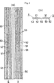
図1は、本発明の実施形態を示すものであって、自動車用エアコンディショナの積層型蒸発器の斜視図である。図2は、チューブエレメントを構成する2枚の皿状プレートと、これらの内部に収容されるインナーフィンとを示す斜視図である。図3の(a)はインナーフィンの側面図、(b)はインナーフィンの横断面図である。図4の(a)はインナーフィンが偏平管部に収容された状態を示す一部拡大横断面図、(b)は(a)のb−b線に沿う一部拡大縦断面図である。図5は、本発明の他の実施形態を示すものであって、(a)はインナーフィンの側面図、(b)はインナーフィンの横断面図である。 FIG. 1 shows an embodiment of the present invention and is a perspective view of a stacked evaporator of an automotive air conditioner. FIG. 2 is a perspective view showing two plate-like plates constituting the tube element and inner fins accommodated therein. 3A is a side view of the inner fin, and FIG. 3B is a cross-sectional view of the inner fin. 4A is a partially enlarged transverse sectional view showing a state in which the inner fin is accommodated in the flat tube portion, and FIG. 4B is a partially enlarged longitudinal sectional view taken along the line bb of FIG. 4A. 5A and 5B show another embodiment of the present invention, in which FIG. 5A is a side view of an inner fin, and FIG. 5B is a cross-sectional view of the inner fin.
図1〜4は、本発明の実施形態を示すものである。図示の実施形態では、本発明を、自動車用エアコンディショナの積層型蒸発器に適用している。 1 to 4 show an embodiment of the present invention. In the illustrated embodiment, the present invention is applied to a laminated evaporator of an automotive air conditioner.
図1は、自動車用エアコンディショナの積層型蒸発器の全体を示すものである。この積層型蒸発器(1)は、対をなす皿状プレート(20)(20A)どうしを向かい合わせに接合してなる複数のチューブエレメント(2)(2A)をアウターフィン(3)を介して接合することにより形成された蒸発器コア(10)を備えている。蒸発器コア(10)は、左端以外のチューブエレメント(2)によって構成された、複数の左右並列状前側偏平管部(22A)、複数の左右並列状後側偏平管部(22A)、前側偏平管部(22A)の上端部どうしおよび下端部どうしを連通させる前側上ヘッダ部(22B)および前側下ヘッダ部(22B)、ならびに後側偏平管部(22A)の上端部どうしおよび下端部どうしを連通させる後側上ヘッダ部(22B)および後側下ヘッダ部(22B)を備えている。左端のチューブエレメント(2A)は、冷媒導入通路(201)および冷媒排出通路(202)を備えている。同チューブエレメント(2A)の外面には、冷媒導入管接続口(41)および冷媒排出管接続口(42)を有する管接続用ブロック(4)が取り付けられている。ヘッダ部(22B)の所要箇所には仕切壁(図示略)が設けられており、冷媒導入管接続口(41)から冷媒導入通路(201)を経て後側上ヘッダ部(22B)の左端部に流入した冷媒が、所定のパターンで全てのヘッダ部(22B)および偏平管部(22A)を流れた後、前側上ヘッダ部(22B)の左端部から冷媒排出通路(202)を経て冷媒排出管接続口(42)から排出されるようになっている。 FIG. 1 shows the entire laminated evaporator of an automotive air conditioner. This laminated evaporator (1) has a plurality of tube elements (2) (2A) formed by joining a pair of plate-like plates (20) (20A) facing each other via outer fins (3). An evaporator core (10) formed by joining is provided. The evaporator core (10) is composed of a plurality of left and right parallel front flat tubes (22A), a plurality of left and right parallel rear flat tubes (22A), and a front flat formed by tube elements (2) other than the left end. The front upper header part (22B) and the front lower header part (22B) communicating the upper end parts and the lower end parts of the pipe part (22A), and the upper end parts and the lower end parts of the rear flat pipe part (22A) A rear upper header portion (22B) and a rear lower header portion (22B) are provided for communication. The leftmost tube element (2A) includes a refrigerant introduction passage (201) and a refrigerant discharge passage (202). A tube connection block (4) having a refrigerant introduction pipe connection port (41) and a refrigerant discharge pipe connection port (42) is attached to the outer surface of the tube element (2A). A partition wall (not shown) is provided at a required portion of the header portion (22B), and the left end portion of the rear upper header portion (22B) through the refrigerant introduction passage (201) from the refrigerant introduction pipe connection port (41). Refrigerant flows into all header parts (22B) and flat tube parts (22A) in a predetermined pattern, and then is discharged from the left end of the front upper header part (22B) through the refrigerant discharge passage (202). It is discharged from the pipe connection port (42).
図2は、左端以外のチューブエレメント(2)を構成する2枚の皿状プレート(20)と、これらの内部に収容されるインナーフィン(5)とを示すものである。皿状プレート(20)は、両面にろう材がクラッドされたブレージングシートからなる。各皿状プレート(20)の幅中央部には、垂直な仕切用凸条(21)が設けられて、同凸条(21)の前後両側が偏平管部形成用凹部(22)となされている。また、各皿状プレート(20)には、前後偏平管部形成用凹部(22)の上下両端に連なるようにヘッダ形成用凹部(23)が設けられ、同凹部(23)の底に冷媒通過孔(24)があけられている。但し、一部の皿状プレート(20)における所要のヘッダ形成用凹部(23)の底には冷媒通過孔(24)があけられておらず、同底によって上記仕切壁が構成されている。そして、両皿状プレート(20)が向かい合わせに接合されることにより、前後2つの偏平管部(22A)が形成される。2つの偏平管部(22A)それぞれに配設されるインナーフィン(5)は、本発明によるインナーフィンによって構成されており、両インナーフィン(5)は、これらの隣り合う縁部どうしが両皿状プレート(20)の仕切用凸条(21)間に介在される連結部(50)を介してつながった、一体構成のものとなされている。 FIG. 2 shows two plate-like plates (20) constituting the tube element (2) other than the left end, and inner fins (5) accommodated in these plates. The dish-shaped plate (20) is made of a brazing sheet having a brazing material clad on both sides. At the center of the width of each plate-like plate (20), a vertical partitioning ridge (21) is provided, and the front and rear sides of the ridge (21) are formed as flat tube portion forming recesses (22). Yes. Each dish-shaped plate (20) is provided with a header forming recess (23) so as to be connected to the upper and lower ends of the front and rear flat tube portion forming recess (22), and the refrigerant passes through the bottom of the recess (23). A hole (24) is drilled. However, the coolant passage hole (24) is not formed in the bottom of a required header forming recess (23) in some of the plate-like plates (20), and the partition wall is constituted by the bottom. Then, the two flat tubes (22A) are formed by joining the two plate-like plates (20) face to face. The inner fin (5) disposed in each of the two flat tube portions (22A) is constituted by the inner fin according to the present invention. The plate-shaped plate (20) has a one-piece structure connected via a connecting portion (50) interposed between partitioning ridges (21).
図2〜4に示すように、本発明によるインナーフィン(5)は、ロールフォーミングによって形成された横断面波形のアルミニウム合金板よりなり、偏平管部(22A)に収容されかつ全ての山頂部(51)および全ての谷底部(52)が偏平管部(22A)内面にろう付けされている。このインナーフィン(5)によって、偏平管部(22A)内に前後方向に並ぶ複数の冷媒通路(221)が形成されている。そして、図3および4に示すように、インナーフィン(5)における複数の谷底部(52)に、これらの接合される側と反対側を向いた乱流促進用凸部(53)が設けられている。 As shown in FIGS. 2 to 4, the inner fin (5) according to the present invention is made of an aluminum alloy plate having a corrugated cross section formed by roll forming, and is accommodated in the flat tube portion (22A) and all peak portions ( 51) and all valley bottoms (52) are brazed to the inner surface of the flat tube portion (22A). The inner fin (5) forms a plurality of refrigerant passages (221) arranged in the front-rear direction in the flat tube portion (22A). As shown in FIGS. 3 and 4, a plurality of valley bottom portions (52) in the inner fin (5) are provided with turbulent flow promotion convex portions (53) facing the side opposite to the side to be joined. ing.
上記インナーフィン(5)は、横断面波形に形成されたアルミニウム合金板を所定長さに切断することによって形成された後、上下に多数枚積み重ねられて一時的に保管される。この状態において、隣り合うインナーフィン(5)どうしは、乱流促進用凸部(53)の存在により密着しない。したがって、積み重ね状態からインナーフィン(5)を1枚ずつ取り出して、蒸発器(1)の組立作業を効率良く行うことができる。 The inner fin (5) is formed by cutting an aluminum alloy plate formed in a corrugated cross section into a predetermined length, and then a large number of the inner fins (5) are stacked and temporarily stored. In this state, the adjacent inner fins (5) are not in close contact with each other due to the presence of the turbulent flow promoting convex portion (53). Therefore, the inner fins (5) can be taken out one by one from the stacked state, and the assembly work of the evaporator (1) can be performed efficiently.
図3に示すように、前後各インナーフィン(5)において、乱流促進用凸部(53)が設けられている谷底部(52)の数は5であって、これは、全ての山頂部(51)と全ての谷底部(52)を合わせた数(=23)の約5分の1に相当する。乱流促進用凸部(53)が設けらている5つの谷底部(52)は、図3の通り、インナーフィン幅方向にランダムに配置されている。上記5つの谷底部(52)における乱流促進用凸部(53)の数は、1〜5個である。 As shown in FIG. 3, in each of the front and rear inner fins (5), the number of valley bottom portions (52) provided with the turbulent flow-protruding convex portions (53) is five, which is the summit portion of all the peaks. This corresponds to approximately one fifth of the total number (= 23) of (51) and all valley bottoms (52). The five valley bottom portions (52) provided with the turbulent flow promoting convex portions (53) are randomly arranged in the inner fin width direction as shown in FIG. The number of the turbulent flow promoting projections (53) in the five valley bottoms (52) is 1 to 5.
図4(b)に示すように、乱流促進用凸部(53)の裏側に形成された凹部(54)と偏平管部(22A)内面との間に生じる隙間は、ろう材(6)によって塞がれている(図4(a)では、ろう材(6)は省略した)。乱流促進用凸部(53)のインナーフィン長さ方向の寸法(A)は1mmであり、同凸部(53)の高さ(B)は0.4mmである。 As shown in FIG.4 (b), the clearance gap produced between the recessed part (54) formed in the back side of the convex part (53) for turbulent flow, and the flat pipe part (22A) is the brazing material (6). (In FIG. 4A, the brazing material (6) is omitted). The dimension (A) in the length direction of the inner fin of the turbulent flow promoting projection (53) is 1 mm, and the height (B) of the projection (53) is 0.4 mm.
上記の蒸発器(1)において、偏平管部(22A)内の冷媒通路(221)を流れる冷媒は、沸騰状態であるため、通常でも乱流状態となっているが、インナーフィン(5)の乱流促進用凸部(53)によって更に程度の大きい乱流状態で流れるように促進され、それによって熱伝達効率が向上する。また、冷媒は、途中で他の冷媒通路(221)に流れ込むことなく、各冷媒通路(221)を真っ直ぐに流れるので、流通抵抗が少ない。 In the evaporator (1), since the refrigerant flowing through the refrigerant passage (221) in the flat tube portion (22A) is in a boiling state, it is normally turbulent, but the inner fin (5) The turbulent flow-promoting convex portion (53) is further promoted to flow in a turbulent state of a greater degree, thereby improving the heat transfer efficiency. Further, since the refrigerant flows straight through each refrigerant passage (221) without flowing into the other refrigerant passages (221) on the way, the flow resistance is low.
図5は、本発明の他の実施形態を示すものである。図5において、連結部(50)を介してつながった前後各インナーフィン(5)には、前後両縁部付近に位置する3つの谷底部(52)に、乱流促進用凸部(53)が設けられている。上記3つの谷底部(52)における凸部(53)の数は、1〜3個である。その他は、図1〜4に示す実施形態とほぼ同じである。 FIG. 5 shows another embodiment of the present invention. In FIG. 5, each of the front and rear inner fins (5) connected through the connecting portion (50) has three valley bottom portions (52) located near both front and rear edges, and a turbulent flow-promoting convex portion (53). Is provided. The number of convex portions (53) in the three valley bottom portions (52) is 1 to 3. Others are almost the same as the embodiment shown in FIGS.
なお、上記の実施形態はあくまでも例示にすぎず、請求の範囲に記載された本発明の要旨を逸脱しない範囲で適宜に変更の上、本発明を実施することは勿論可能である。 The above-described embodiment is merely an example, and it is needless to say that the present invention can be implemented with appropriate modifications without departing from the scope of the present invention described in the claims.
以上のように、本発明は、内部にインナーフィンが配設された偏平管を備えた熱交換器の高性能化に有用であり、特に、自動車用エアコンディショナの蒸発器のような蒸発器の高性能化に有用である。 INDUSTRIAL APPLICABILITY As described above, the present invention is useful for improving the performance of a heat exchanger having a flat tube having an inner fin disposed therein, and in particular, an evaporator such as an evaporator of an automotive air conditioner. It is useful for improving the performance.
Claims (5)
インナーフィンの全ての山頂部および全ての谷底部のうち少なくともいずれか1つに、これらのろう付けされる側と反対側を向いた乱流促進用凸部が設けられており、乱流促進用凸部の裏側に形成された凹部と偏平管内面との間に生じる隙間がろう材によって塞がれていることを特徴とする、蒸発器。 A plurality of the flat tubes made of a metal plate of cross-sectional waveform, is housed in the flat tubes, evaporator and all the crest and every valley bottom and a Lee N'nafin being brazed to the flat inner surface In
At least one of all the peak portions and all the valley bottom portions of the inner fin is provided with a turbulent flow-promoting convex portion facing the side to be brazed, for turbulent flow promotion. and wherein the gap formed between the back side formed concave portion and the flat inner surface of the convex portion is peeling busy by the brazing material, the evaporator.
Applications Claiming Priority (3)
| Application Number | Priority Date | Filing Date | Title |
|---|---|---|---|
| JP2001012653 | 2001-01-22 | ||
| US30265401P | 2001-07-05 | 2001-07-05 | |
| PCT/JP2002/000373 WO2002057700A1 (en) | 2001-01-22 | 2002-01-21 | Inner fin for heat exchanger flat tubes and evaporator |
Publications (3)
| Publication Number | Publication Date |
|---|---|
| JP2005506505A JP2005506505A (en) | 2005-03-03 |
| JP2005506505A5 JP2005506505A5 (en) | 2006-01-05 |
| JP4157768B2 true JP4157768B2 (en) | 2008-10-01 |
Family
ID=26608033
Family Applications (1)
| Application Number | Title | Priority Date | Filing Date |
|---|---|---|---|
| JP2002557736A Expired - Fee Related JP4157768B2 (en) | 2001-01-22 | 2002-01-21 | Evaporator |
Country Status (7)
| Country | Link |
|---|---|
| US (1) | US6948557B2 (en) |
| EP (1) | EP1370817A4 (en) |
| JP (1) | JP4157768B2 (en) |
| KR (1) | KR100826042B1 (en) |
| CN (1) | CN1284959C (en) |
| AU (1) | AU2002225448B2 (en) |
| WO (1) | WO2002057700A1 (en) |
Families Citing this family (14)
| Publication number | Priority date | Publication date | Assignee | Title |
|---|---|---|---|---|
| JP4227172B2 (en) * | 2003-03-26 | 2009-02-18 | カルソニックカンセイ株式会社 | Inner fin with cutout window for heat exchanger |
| JP4493407B2 (en) * | 2004-05-27 | 2010-06-30 | サンデン株式会社 | Laminated heat exchanger and manufacturing method thereof |
| DE102004041308A1 (en) * | 2004-08-25 | 2006-03-02 | Behr Gmbh & Co. Kg | cooler |
| US7363769B2 (en) * | 2005-03-09 | 2008-04-29 | Kelix Heat Transfer Systems, Llc | Electromagnetic signal transmission/reception tower and accompanying base station employing system of coaxial-flow heat exchanging structures installed in well bores to thermally control the environment housing electronic equipment within the base station |
| DE102005034997A1 (en) * | 2005-07-27 | 2007-02-01 | Behr Gmbh & Co. Kg | heat exchangers |
| US8205642B2 (en) | 2007-04-16 | 2012-06-26 | Celltech Metals, Inc. | Flow-through sandwich core structure and method and system for same |
| JP5061065B2 (en) * | 2008-08-26 | 2012-10-31 | 株式会社豊田自動織機 | Liquid cooling system |
| JP5898995B2 (en) * | 2012-02-20 | 2016-04-06 | 株式会社ケーヒン・サーマル・テクノロジー | Manufacturing method of evaporator with cold storage function for car air conditioner |
| FR2997482B1 (en) * | 2012-10-25 | 2018-07-27 | Valeo Systemes Thermiques | ELECTRIC THERMAL MODULE AND HEAT EXCHANGER COMPRISING SUCH A MODULE. |
| WO2016038419A1 (en) | 2014-09-09 | 2016-03-17 | Bombardier Recreational Products Inc. | Heat exchanger for a snowmobile engine air intake |
| RU2675303C2 (en) | 2014-09-09 | 2018-12-18 | Бомбардье Рекриэйшенел Продактс Инк. | Heat exchanger for snowmobile |
| CN109186293A (en) * | 2018-10-12 | 2019-01-11 | 纪彦竹 | A kind of pleated sheet fin heat exchanger |
| CN114829865A (en) * | 2019-12-27 | 2022-07-29 | 株式会社久保田 | Thermal decomposition tube with fluid stirring element |
| CN113280544A (en) * | 2021-05-14 | 2021-08-20 | 章世燕 | Edible ice generator |
Family Cites Families (10)
| Publication number | Priority date | Publication date | Assignee | Title |
|---|---|---|---|---|
| US2488615A (en) * | 1942-11-11 | 1949-11-22 | Modine Mfg Co | Oil cooler tube |
| GB1599395A (en) * | 1978-05-12 | 1981-09-30 | Imi Marston Radiators Ltd | Heat exchanger |
| JPS57105690A (en) * | 1980-12-24 | 1982-07-01 | Nippon Denso Co Ltd | Heat exchanger |
| JPS58221390A (en) * | 1982-06-18 | 1983-12-23 | Nippon Denso Co Ltd | Heat exchanger |
| JP2936710B2 (en) * | 1990-11-29 | 1999-08-23 | 株式会社デンソー | Tube for flowing heat medium of heat-to-light converter and method of manufacturing the same |
| JP3405997B2 (en) * | 1991-10-23 | 2003-05-12 | 株式会社デンソー | Inner fin and manufacturing method thereof |
| JPH0674677A (en) * | 1992-08-27 | 1994-03-18 | Mitsubishi Heavy Ind Ltd | Manufacture of lamination type heat exchanger |
| GB9511847D0 (en) * | 1995-06-10 | 1995-08-09 | Metsec Plc | Metal strip |
| JPH11309564A (en) * | 1998-04-28 | 1999-11-09 | Denso Corp | Heat exchanger |
| JP3624282B2 (en) * | 1999-05-12 | 2005-03-02 | 昭和電工株式会社 | Laminate heat exchanger |
-
2002
- 2002-01-21 KR KR1020037009615A patent/KR100826042B1/en not_active IP Right Cessation
- 2002-01-21 EP EP02715840A patent/EP1370817A4/en not_active Withdrawn
- 2002-01-21 US US10/466,833 patent/US6948557B2/en not_active Expired - Lifetime
- 2002-01-21 AU AU2002225448A patent/AU2002225448B2/en not_active Ceased
- 2002-01-21 CN CNB02803936XA patent/CN1284959C/en not_active Expired - Lifetime
- 2002-01-21 WO PCT/JP2002/000373 patent/WO2002057700A1/en active Application Filing
- 2002-01-21 JP JP2002557736A patent/JP4157768B2/en not_active Expired - Fee Related
Also Published As
| Publication number | Publication date |
|---|---|
| US20040050541A1 (en) | 2004-03-18 |
| KR100826042B1 (en) | 2008-04-28 |
| JP2005506505A (en) | 2005-03-03 |
| WO2002057700A1 (en) | 2002-07-25 |
| CN1284959C (en) | 2006-11-15 |
| US6948557B2 (en) | 2005-09-27 |
| EP1370817A1 (en) | 2003-12-17 |
| CN1488063A (en) | 2004-04-07 |
| EP1370817A4 (en) | 2008-03-05 |
| AU2002225448B2 (en) | 2006-03-02 |
| KR20030072601A (en) | 2003-09-15 |
Similar Documents
| Publication | Publication Date | Title |
|---|---|---|
| JP4157768B2 (en) | Evaporator | |
| JP4946348B2 (en) | Air heat exchanger | |
| CA2372399A1 (en) | Low profile finned heat exchanger | |
| JP2005506505A5 (en) | ||
| US6644389B1 (en) | Fin tube heat exchanger | |
| JP2004530092A (en) | Heat exchanger | |
| JP2004530092A5 (en) | ||
| JP4190289B2 (en) | Heat exchanger | |
| US6942024B2 (en) | Corrugated heat exchange element | |
| WO2017002819A1 (en) | Inner fin for heat exchanger | |
| JPH0674678A (en) | Lamination type heat exchanger and manufacture thereof | |
| EP0838650B1 (en) | Humped plate fin heat exchangers | |
| JP2007113793A (en) | Evaporator | |
| JPH079865A (en) | Radiator for electric vehicle | |
| JP2001133192A (en) | Heat exchanger | |
| JP4630591B2 (en) | Heat exchanger | |
| JP2001255093A (en) | Evaporator | |
| JPS61193733A (en) | Manufacture of heat exchanger | |
| JP2884201B2 (en) | Heat exchanger | |
| JPH09273830A (en) | Evaporator | |
| JP2001027488A (en) | Lamination type heat-exchanger | |
| KR100528997B1 (en) | Multilayer Heat Exchanger | |
| KR100833482B1 (en) | Finless-typed heat exchanger | |
| JP2941768B1 (en) | Stacked heat exchanger | |
| JP3108913B2 (en) | Oil cooler juxtaposed with aftercooler |
Legal Events
| Date | Code | Title | Description |
|---|---|---|---|
| A521 | Written amendment |
Free format text: JAPANESE INTERMEDIATE CODE: A523 Effective date: 20050114 |
|
| A621 | Written request for application examination |
Free format text: JAPANESE INTERMEDIATE CODE: A621 Effective date: 20050114 |
|
| A131 | Notification of reasons for refusal |
Free format text: JAPANESE INTERMEDIATE CODE: A131 Effective date: 20080108 |
|
| A521 | Written amendment |
Free format text: JAPANESE INTERMEDIATE CODE: A523 Effective date: 20080225 |
|
| TRDD | Decision of grant or rejection written | ||
| A01 | Written decision to grant a patent or to grant a registration (utility model) |
Free format text: JAPANESE INTERMEDIATE CODE: A01 Effective date: 20080617 |
|
| A01 | Written decision to grant a patent or to grant a registration (utility model) |
Free format text: JAPANESE INTERMEDIATE CODE: A01 |
|
| A61 | First payment of annual fees (during grant procedure) |
Free format text: JAPANESE INTERMEDIATE CODE: A61 Effective date: 20080714 |
|
| FPAY | Renewal fee payment (event date is renewal date of database) |
Free format text: PAYMENT UNTIL: 20110718 Year of fee payment: 3 |
|
| R150 | Certificate of patent or registration of utility model |
Free format text: JAPANESE INTERMEDIATE CODE: R150 |
|
| FPAY | Renewal fee payment (event date is renewal date of database) |
Free format text: PAYMENT UNTIL: 20110718 Year of fee payment: 3 |
|
| FPAY | Renewal fee payment (event date is renewal date of database) |
Free format text: PAYMENT UNTIL: 20140718 Year of fee payment: 6 |
|
| FPAY | Renewal fee payment (event date is renewal date of database) |
Free format text: PAYMENT UNTIL: 20140718 Year of fee payment: 6 |
|
| FPAY | Renewal fee payment (event date is renewal date of database) |
Free format text: PAYMENT UNTIL: 20140718 Year of fee payment: 6 |
|
| FPAY | Renewal fee payment (event date is renewal date of database) |
Free format text: PAYMENT UNTIL: 20140718 Year of fee payment: 6 |
|
| FPAY | Renewal fee payment (event date is renewal date of database) |
Free format text: PAYMENT UNTIL: 20140718 Year of fee payment: 6 |
|
| S111 | Request for change of ownership or part of ownership |
Free format text: JAPANESE INTERMEDIATE CODE: R313113 |
|
| R250 | Receipt of annual fees |
Free format text: JAPANESE INTERMEDIATE CODE: R250 |
|
| R250 | Receipt of annual fees |
Free format text: JAPANESE INTERMEDIATE CODE: R250 |
|
| R250 | Receipt of annual fees |
Free format text: JAPANESE INTERMEDIATE CODE: R250 |
|
| R250 | Receipt of annual fees |
Free format text: JAPANESE INTERMEDIATE CODE: R250 |
|
| LAPS | Cancellation because of no payment of annual fees |