JP4156376B2 - System for enriching bodily fluids with gas - Google Patents
System for enriching bodily fluids with gas Download PDFInfo
- Publication number
- JP4156376B2 JP4156376B2 JP2002573071A JP2002573071A JP4156376B2 JP 4156376 B2 JP4156376 B2 JP 4156376B2 JP 2002573071 A JP2002573071 A JP 2002573071A JP 2002573071 A JP2002573071 A JP 2002573071A JP 4156376 B2 JP4156376 B2 JP 4156376B2
- Authority
- JP
- Japan
- Prior art keywords
- fluid
- signal
- flow
- gas
- blood
- Prior art date
- Legal status (The legal status is an assumption and is not a legal conclusion. Google has not performed a legal analysis and makes no representation as to the accuracy of the status listed.)
- Expired - Fee Related
Links
Images


Classifications
-
- A—HUMAN NECESSITIES
- A61—MEDICAL OR VETERINARY SCIENCE; HYGIENE
- A61M—DEVICES FOR INTRODUCING MEDIA INTO, OR ONTO, THE BODY; DEVICES FOR TRANSDUCING BODY MEDIA OR FOR TAKING MEDIA FROM THE BODY; DEVICES FOR PRODUCING OR ENDING SLEEP OR STUPOR
- A61M1/00—Suction or pumping devices for medical purposes; Devices for carrying-off, for treatment of, or for carrying-over, body-liquids; Drainage systems
- A61M1/36—Other treatment of blood in a by-pass of the natural circulatory system, e.g. temperature adaptation, irradiation ; Extra-corporeal blood circuits
- A61M1/3621—Extra-corporeal blood circuits
- A61M1/3663—Flow rate transducers; Flow integrators
-
- A—HUMAN NECESSITIES
- A61—MEDICAL OR VETERINARY SCIENCE; HYGIENE
- A61M—DEVICES FOR INTRODUCING MEDIA INTO, OR ONTO, THE BODY; DEVICES FOR TRANSDUCING BODY MEDIA OR FOR TAKING MEDIA FROM THE BODY; DEVICES FOR PRODUCING OR ENDING SLEEP OR STUPOR
- A61M1/00—Suction or pumping devices for medical purposes; Devices for carrying-off, for treatment of, or for carrying-over, body-liquids; Drainage systems
- A61M1/14—Dialysis systems; Artificial kidneys; Blood oxygenators ; Reciprocating systems for treatment of body fluids, e.g. single needle systems for hemofiltration or pheresis
- A61M1/32—Oxygenators without membranes
-
- A—HUMAN NECESSITIES
- A61—MEDICAL OR VETERINARY SCIENCE; HYGIENE
- A61M—DEVICES FOR INTRODUCING MEDIA INTO, OR ONTO, THE BODY; DEVICES FOR TRANSDUCING BODY MEDIA OR FOR TAKING MEDIA FROM THE BODY; DEVICES FOR PRODUCING OR ENDING SLEEP OR STUPOR
- A61M1/00—Suction or pumping devices for medical purposes; Devices for carrying-off, for treatment of, or for carrying-over, body-liquids; Drainage systems
- A61M1/36—Other treatment of blood in a by-pass of the natural circulatory system, e.g. temperature adaptation, irradiation ; Extra-corporeal blood circuits
- A61M1/3621—Extra-corporeal blood circuits
- A61M1/3622—Extra-corporeal blood circuits with a cassette forming partially or totally the blood circuit
- A61M1/36222—Details related to the interface between cassette and machine
- A61M1/362227—Details related to the interface between cassette and machine the interface providing means for actuating on functional elements of the cassette, e.g. plungers
-
- A—HUMAN NECESSITIES
- A61—MEDICAL OR VETERINARY SCIENCE; HYGIENE
- A61M—DEVICES FOR INTRODUCING MEDIA INTO, OR ONTO, THE BODY; DEVICES FOR TRANSDUCING BODY MEDIA OR FOR TAKING MEDIA FROM THE BODY; DEVICES FOR PRODUCING OR ENDING SLEEP OR STUPOR
- A61M1/00—Suction or pumping devices for medical purposes; Devices for carrying-off, for treatment of, or for carrying-over, body-liquids; Drainage systems
- A61M1/36—Other treatment of blood in a by-pass of the natural circulatory system, e.g. temperature adaptation, irradiation ; Extra-corporeal blood circuits
- A61M1/3621—Extra-corporeal blood circuits
- A61M1/3622—Extra-corporeal blood circuits with a cassette forming partially or totally the blood circuit
- A61M1/36224—Extra-corporeal blood circuits with a cassette forming partially or totally the blood circuit with sensing means or components thereof
-
- A—HUMAN NECESSITIES
- A61—MEDICAL OR VETERINARY SCIENCE; HYGIENE
- A61M—DEVICES FOR INTRODUCING MEDIA INTO, OR ONTO, THE BODY; DEVICES FOR TRANSDUCING BODY MEDIA OR FOR TAKING MEDIA FROM THE BODY; DEVICES FOR PRODUCING OR ENDING SLEEP OR STUPOR
- A61M1/00—Suction or pumping devices for medical purposes; Devices for carrying-off, for treatment of, or for carrying-over, body-liquids; Drainage systems
- A61M1/36—Other treatment of blood in a by-pass of the natural circulatory system, e.g. temperature adaptation, irradiation ; Extra-corporeal blood circuits
- A61M1/3621—Extra-corporeal blood circuits
- A61M1/3622—Extra-corporeal blood circuits with a cassette forming partially or totally the blood circuit
- A61M1/36226—Constructional details of cassettes, e.g. specific details on material or shape
- A61M1/362262—Details of incorporated reservoirs
-
- A—HUMAN NECESSITIES
- A61—MEDICAL OR VETERINARY SCIENCE; HYGIENE
- A61M—DEVICES FOR INTRODUCING MEDIA INTO, OR ONTO, THE BODY; DEVICES FOR TRANSDUCING BODY MEDIA OR FOR TAKING MEDIA FROM THE BODY; DEVICES FOR PRODUCING OR ENDING SLEEP OR STUPOR
- A61M1/00—Suction or pumping devices for medical purposes; Devices for carrying-off, for treatment of, or for carrying-over, body-liquids; Drainage systems
- A61M1/36—Other treatment of blood in a by-pass of the natural circulatory system, e.g. temperature adaptation, irradiation ; Extra-corporeal blood circuits
- A61M1/3621—Extra-corporeal blood circuits
- A61M1/3622—Extra-corporeal blood circuits with a cassette forming partially or totally the blood circuit
- A61M1/36226—Constructional details of cassettes, e.g. specific details on material or shape
- A61M1/362265—Details of valves
-
- A—HUMAN NECESSITIES
- A61—MEDICAL OR VETERINARY SCIENCE; HYGIENE
- A61M—DEVICES FOR INTRODUCING MEDIA INTO, OR ONTO, THE BODY; DEVICES FOR TRANSDUCING BODY MEDIA OR FOR TAKING MEDIA FROM THE BODY; DEVICES FOR PRODUCING OR ENDING SLEEP OR STUPOR
- A61M1/00—Suction or pumping devices for medical purposes; Devices for carrying-off, for treatment of, or for carrying-over, body-liquids; Drainage systems
- A61M1/36—Other treatment of blood in a by-pass of the natural circulatory system, e.g. temperature adaptation, irradiation ; Extra-corporeal blood circuits
- A61M1/3621—Extra-corporeal blood circuits
- A61M1/3626—Gas bubble detectors
-
- A—HUMAN NECESSITIES
- A61—MEDICAL OR VETERINARY SCIENCE; HYGIENE
- A61M—DEVICES FOR INTRODUCING MEDIA INTO, OR ONTO, THE BODY; DEVICES FOR TRANSDUCING BODY MEDIA OR FOR TAKING MEDIA FROM THE BODY; DEVICES FOR PRODUCING OR ENDING SLEEP OR STUPOR
- A61M1/00—Suction or pumping devices for medical purposes; Devices for carrying-off, for treatment of, or for carrying-over, body-liquids; Drainage systems
- A61M1/36—Other treatment of blood in a by-pass of the natural circulatory system, e.g. temperature adaptation, irradiation ; Extra-corporeal blood circuits
- A61M1/3621—Extra-corporeal blood circuits
- A61M1/3623—Means for actively controlling temperature of blood
Abstract
Description
本発明は、概略的には、ガス富化流体に関し、更に詳細には、体内流体をガスで富化するためのシステムに関する。 The present invention relates generally to gas-enriched fluids, and more particularly to a system for enriching bodily fluids with gas.
この項目部分は、以下に説明すると共に(或いは)請求の対象とする本発明の種々の特徴に関する技術の種々の特徴を、読者が理解できるようにすることを意図している。この説明は、読者に本発明の種々の特徴のより深い理解を容易にする背景技術の情報を提供するのに役立つと考えられる。したがって、かかる説明は、従来技術の紹介としてではなく、この点に照らして読まれるべきことは言うまでもない。
ガス富化流体は、多様な医用、商用及び工業用途で用いられている。用途に応じて、特定のタイプの流体が、特定のタイプのガスで富化されて所与の用途についてガス又は流体単独の性質よりも優れた性質を持つガス富化流体が作られる。また、ガス富化流体を送出する方法は、この場合も、ガス富化流体が用いられる特定のタイプの用途に応じて極めて様々である。
多くの商業的及び工業的用途が存在する。一例として、飲料を酸素の追加により浄化し、二酸化炭素の追加により炭酸ガス飽和させる。別の例として、廃水の浄化は、好気菌による生物分解を容易にするよう酸素の添加により高められる。更に別の例として、消火剤では、不活性ガス、例えば、窒素、二酸化炭素又はアルゴンを水又は他の適当な流体中に溶解させて衝撃の際に膨張して火を消すガス富化流体を作ることができる。
This section of the section is intended to allow the reader to understand various features of the technology that are described below and / or related to the various features of the claimed invention. This description is believed to help provide the reader with background information that facilitates a deeper understanding of the various features of the present invention. Thus, it should be understood that such an explanation should not be read as an introduction to the prior art, but in light of this point.
Gas-enriched fluids are used in a variety of medical, commercial and industrial applications. Depending on the application, a particular type of fluid is enriched with a particular type of gas to create a gas-enriched fluid that has properties superior to those of the gas or fluid alone for a given application. Again, the method of delivering the gas-enriched fluid is quite varied depending on the particular type of application in which the gas-enriched fluid is used.
There are many commercial and industrial applications. As an example, the beverage is purified by the addition of oxygen and saturated with carbon dioxide by the addition of carbon dioxide. As another example, the purification of wastewater is enhanced by the addition of oxygen to facilitate biodegradation by aerobic bacteria. As yet another example, a fire extinguisher may be a gas-enriched fluid that dissolves an inert gas such as nitrogen, carbon dioxide or argon in water or other suitable fluid and expands upon impact to extinguish the fire. Can be made.
ガス富化流体の商業的及び工業的用途は比較的よく知られているが、ガス富化流体は、健康管理産業に進出し続けている。例えば、酸素療法は、多くの領域において次第に普及している。酸素、オゾン、H2O2及び他の活性酸素サプリメントを伴う治療の幅広い組合せは、事実上、全ての医療専門家の間、とりわけ開業医の支持を受けている。酸素療法は、種々の病気の治療に利用されており、かかる病気としては、癌、AIDS及びアルツハイマーが挙げられる。例えば、オゾン療法は、エクセマ(excema)、壊疽、癌、発作、胆炎、ヘルペス及びAIDSを含む種々の医療条件のためにヨーロッパにおいて数百万人の人を治療するのに用いられている。かかるオゾン療法は、ヨーロッパでは普及している。というのは、かかるオゾン療法は、酸素代謝を促進し、血流中の酸素の放出を刺激する傾向があるからである。
酸素は、人の細胞にとって重要な養分である。酸素は、健康な細胞活動のためのエネルギを作り、体内の異物としての毒素に直接作用する。確かに、セルの損傷は、たとえ僅かな期間の間であっても酸素欠乏に起因して生じる場合があり、かかる細胞の損傷は器官の機能不全又は障害の原因となる場合がある。例えば、心臓病及び心臓発作の被害者は、血液中の酸素が生組織の細胞に送られるのを阻止する血液の血流障害又は発散を経験する。酸素が無ければ、これら組織は次第に退化し、深刻な場合では、完全な器官の不全により死に至る場合がある。しかしながら、深刻さの低い場合であってもこれらは、費用のかかる入院や専門的な治療、そして長期間にわたるリハビリを必要とする場合がある。
Although commercial and industrial applications of gas-enriched fluids are relatively well known, gas-enriched fluids continue to enter the health care industry. For example, oxygen therapy is becoming increasingly popular in many areas. A broad combination of treatments with oxygen, ozone, H 2 O 2 and other active oxygen supplements has gained the support of virtually all medical professionals, especially practitioners. Oxygen therapy is used to treat a variety of diseases, such as cancer, AIDS, and Alzheimer. For example, ozone therapy has been used to treat millions of people in Europe for a variety of medical conditions including excema, gangrene, cancer, stroke, cholecystitis, herpes and AIDS. Such ozone therapy is prevalent in Europe. This is because such ozone therapy tends to promote oxygen metabolism and stimulate the release of oxygen in the bloodstream.
Oxygen is an important nutrient for human cells. Oxygen creates energy for healthy cellular activity and acts directly on toxins as foreign bodies in the body. Indeed, cell damage can occur due to oxygen deprivation even for a brief period of time, and such cell damage can cause organ dysfunction or failure. For example, victims of heart disease and strokes experience blood flow disturbances or divergences that block oxygen in the blood from being sent to living tissue cells. Without oxygen, these tissues gradually degenerate and, in severe cases, can be fatal due to complete organ failure. However, even in less severe cases, these may require costly hospitalization, professional treatment, and long-term rehabilitation.
血液中の酸素レベルは、酸素の所与の分圧(pO2)における飽和溶液内で達成できる酸素の濃度で表すことができる。代表的には、動脈血の場合、通常の酸素レベル、即ち、酸素正常状態又は血中酸素正常状態は、90〜110mmHgである。低酸素血、即ち、血中酸素減少は、pO2が90mmHg未満の動脈血である。高酸素血、即ち、血中酸素過剰又は酸素過剰は、pO2が400mmHgよりも大きく760mmHgよりも小さい動脈血である。高比重性血は、pO2が760mmHgよりも大きい動脈血である。他方、静脈血は、代表的には、pO2レベルが90mmHg未満である。大人の平均では、例えば、通常の静脈血酸素レベルは、一般に40mmHg〜70mmHgである。
血中の酸素レベルは又、ヘモグロビンの飽和レベルで表すことができる。通常の動脈血の場合、ヘモグロビンの飽和度は、約97%であり、pO2レベルが増加するときに変化するに過ぎない。通常の静脈血の場合、ヘモグロビンの飽和度は、約75%である。実のところ、ヘモグロビンは、通常、血液中の主要な酸素運搬成分である。しかしながら、酸素の移動は、ヘモグロビンから血漿を通って体の組織の中へと起こる。したがって、血漿は、相当多くの量の酸素を運ぶことが可能である。ただし、血漿は、通常、そのようにはしない。かくして、血液中の酸素レベルを増大させる技術は、主として、ヘモグロビンではなく血漿の酸素レベルを高める。
The oxygen level in the blood can be expressed as the concentration of oxygen that can be achieved in a saturated solution at a given partial pressure of oxygen (pO 2 ). Typically, in the case of arterial blood, the normal oxygen level, ie, normoxia or normoxia, is 90-110 mmHg. Hypoxemia, or blood oxygen reduction, is arterial blood with a pO 2 of less than 90 mmHg. Hyperoxia, ie, blood oxygen excess or oxygen excess, is arterial blood with a pO 2 greater than 400 mmHg and less than 760 mmHg. High density blood is arterial blood with a pO 2 greater than 760 mmHg. On the other hand, venous blood typically has a pO 2 level of less than 90 mmHg. On average for adults, for example, normal venous oxygen levels are generally between 40 mmHg and 70 mmHg.
The oxygen level in the blood can also be expressed as the saturation level of hemoglobin. In the case of normal arterial blood, hemoglobin saturation is approximately 97% and only changes as pO 2 levels increase. For normal venous blood, hemoglobin saturation is approximately 75%. In fact, hemoglobin is usually the major oxygen-carrying component in the blood. However, oxygen transfer occurs from hemoglobin through the plasma and into the body tissue. Thus, plasma can carry a significant amount of oxygen. However, plasma usually does not. Thus, techniques that increase oxygen levels in the blood primarily increase plasma oxygen levels rather than hemoglobin.
血液中の酸素レベルを増大させる技術は、知られていないというわけではない。例えば、海軍及びレクリレーションのダイバーは、潜水病と戦うために用いられる高圧チャンバ治療に精通している。ただし、高圧医薬品は大抵の人には比較的馴染みがない。ヘモグロビンは酸素で比較的飽和されるので、高圧チャンバ治療は、血漿に酸素を添加しようとするものである。かかる過剰酸素添加(酸素化)は、体の白血球に活力を与えるものと考えられ、かかる白血球は、感染と戦う細胞である。高圧酸素治療は又、放射線障害で苦しむ患者に対して行うことができる。放射線障害は、通常、癌の治療と関連して生じ、この場合、放射線は腫瘍を破壊するために用いられる。残念ながら、現時点においては、放射線治療も又、周囲の健康な組織も傷つける。身体は、細胞相互間の酸素の一定の流れを維持することによりその健康を保つが、放射線治療は、この酸素の流れを遮る。したがって、酸素過剰は、新しい細胞の成長を刺激することができ、かくして、身体を自然治癒させることができる。
放射線治療は、細胞から酸素を奪う唯一の医療のタイプではない。例えば、急性心筋梗塞で悩む患者では、もし心筋層から長期間にわたって適当なレベルの酸素添加血液が奪われると、結果的に心臓に対し不可逆的な損傷が生じる場合がある。心筋梗塞は、心臓発作で発現する場合、冠動脈は、心臓の筋肉への適当な血液の流れを提供しなくなる。急性心筋梗塞又は心筋虚血の治療では、血管壁内の閉塞部を圧迫し、切除し又は治療するために、血管の血管形成術又はステント留置を行う場合が多い。血管形成術では、例えば、バルーンを血管内に配置し、短期間膨らませて血管の内径を大きくする。バルーンをしぼませると、血管の内部は、願わくは、この内径の増大分のほとんど又は全てを保持し、それにより、血液の流れを増大させることができる。
Techniques for increasing oxygen levels in the blood are not unknown. For example, navy and recreational divers are familiar with the high pressure chamber treatment used to combat diving disease. However, high-pressure drugs are relatively unfamiliar to most people. Because hemoglobin is relatively saturated with oxygen, high pressure chamber treatment is an attempt to add oxygen to the plasma. Such excess oxygenation (oxygenation) is thought to give vitality to the body's white blood cells, which are cells that fight infection. Hyperbaric oxygen therapy can also be given to patients suffering from radiation damage. Radiation damage usually occurs in connection with the treatment of cancer, where radiation is used to destroy the tumor. Unfortunately, at present, radiation therapy also harms the surrounding healthy tissue. The body maintains its health by maintaining a constant flow of oxygen between cells, but radiation therapy blocks this flow of oxygen. Thus, excess oxygen can stimulate the growth of new cells and thus allow the body to heal naturally.
Radiation therapy is not the only medical type that deprives cells of oxygen. For example, in patients suffering from acute myocardial infarction, if an appropriate level of oxygenated blood is deprived from the myocardium for an extended period of time, irreversible damage to the heart may result. When myocardial infarction develops in a heart attack, the coronary arteries no longer provide adequate blood flow to the heart muscle. In the treatment of acute myocardial infarction or myocardial ischemia, vascular angioplasty or stent placement is often performed to compress, resect or treat an occlusion in a blood vessel wall. In angioplasty, for example, a balloon is placed in a blood vessel and inflated for a short period of time to increase the inner diameter of the blood vessel. When the balloon is deflated, the interior of the blood vessel can hopefully retain most or all of this increase in inner diameter, thereby increasing blood flow.
しかしながら、閉塞血管に対して成功率の高い治療であっても、組織損傷の恐れは依然として存在する。経皮経管的冠動脈形成術(PTCA)の実施中、バルーンの膨らまし時間は、バルーンの膨らまし中に血管内の血液の流れの一時的な閉塞により引き起こされる虚血に対する患者の許容度によって制限される。虚血は、酸素の需要が酸素の供給を上回る状態であり、この状態は、細胞の損傷又は壊死の原因となる場合がある。再灌流による損傷も又、例えば、形成術後のゆっくりとした冠血管のリフローが遅いこと又はリフローがないことによって生じる場合がある。さらに、或る患者にとっては、形成術による処置は、血管閉塞の治療の魅力的な選択肢ではない。かかる患者は、一般的には、種々の理由、例えば、貧弱な左心室の機能、外傷タイプ及び場所、或いは危険な状態にある心筋層の量により虚血の恐れが増大する。かかる患者の治療の選択肢としては、一般には、より侵襲性の高い処置、例えば、冠血管バイパス術が挙げられる。 However, even with a successful treatment for occluded vessels, there is still a risk of tissue damage. During the performance of percutaneous transluminal coronary angioplasty (PTCA), balloon inflation time is limited by the patient's tolerance to ischemia caused by temporary blockage of blood flow in the blood vessel during balloon inflation. The Ischemia is a condition in which the demand for oxygen exceeds the supply of oxygen, which may cause cell damage or necrosis. Injuries due to reperfusion can also be caused, for example, by slow or no reflow of slow coronary vessels after plastic surgery. Furthermore, for some patients, plastic surgery is not an attractive option for the treatment of vascular occlusion. Such patients generally have an increased risk of ischemia due to various reasons, such as poor left ventricular function, trauma type and location, or the amount of myocardium at risk. Treatment options for such patients generally include more invasive procedures, such as coronary bypass.
急性心筋梗塞及び心筋虚血の治療と関連した組織損傷の恐れを減少させるため、通常、危険な状態にある組織に酸素添加血液又は酸素富化流体を送ることが望ましい。組織損傷は、血液から組織への溶解酸素の拡散により最小限に抑えられ又は防止される。かくして、或る場合には、急性心筋梗塞及び心筋虚血の治療は、酸素添加血液又は酸素富化流体の灌流を含む。「灌流」という用語は、フランス語の動詞“perfuse ”に由来しており、「注ぎかける」とか「注入する」を意味している。しかしながら、本発明の関連では、灌流は、患者の血液の少なくとも一部が、体外循環回路、即ち、患者の体外での血液循環を可能にする回路中へ進路が変えられる種々の技術を意味している。体外回路は、血液を患者に送り戻す前に内部器官の機能に取って代わる人工器官を有している。現在、患者の器官に代用される体外回路中に配置できる多くの人工器官がある。人工器官の例としては、人工心臓(血液ポンプ)、人工肺(酸素供給器)、人工腎(血液透析)及び人工肝が挙げられる。
例えば、PTCA中、許容できるバルーンの膨らまし時間は、患者の冠動脈中に酸素添加血液を同時に導入することによって長くすることができる。血液中の酸素レベルの増大によっても、通常灌流された左心室の心組織に高収縮性が生じ、それにより治療を受けた冠血管を通る血液の流れが一段と増加する。酸素添加血液又は酸素富化流体の注入も又、PTCA又は他の処置、例えば外科手術の完了に続き続けられて虚血の逆転を促進すると共に心筋機能の回復を容易にする。
In order to reduce the risk of tissue damage associated with the treatment of acute myocardial infarction and myocardial ischemia, it is usually desirable to deliver oxygenated blood or oxygen-enriched fluid to the tissue at risk. Tissue damage is minimized or prevented by the diffusion of dissolved oxygen from the blood to the tissue. Thus, in some cases, treatment of acute myocardial infarction and myocardial ischemia involves perfusion of oxygenated blood or oxygen enriched fluid. The term “perfusion” comes from the French verb “perfuse” and means “pouring” or “injecting”. However, in the context of the present invention, perfusion refers to various techniques in which at least a portion of a patient's blood is diverted into an extracorporeal circuit, i.e., a circuit that allows blood circulation outside the patient. ing. The extracorporeal circuit has a prosthesis that replaces the function of the internal organs before sending blood back to the patient. Currently, there are many prostheses that can be placed in extracorporeal circuits that are substituted for patient organs. Examples of artificial organs include an artificial heart (blood pump), an artificial lung (oxygen supply), an artificial kidney (hemodialysis), and an artificial liver.
For example, during PTCA, acceptable balloon inflation time can be increased by simultaneously introducing oxygenated blood into the patient's coronary artery. Increased oxygen levels in the blood also cause high contractility in the normally perfused left ventricular heart tissue, thereby further increasing blood flow through the treated coronary vessels. Infusion of oxygenated blood or oxygen-enriched fluid also continues following PTCA or other procedures, such as surgery, to promote ischemia reversal and facilitate myocardial function recovery.
酸素添加血液又は酸素富化流体を組織に送出する従来方法では、酸素供給器が用いられている。かかる方法は、概略的には、血液を患者から抜き取り、血液を酸素供給器中へ循環させて血液酸素濃度を増大させ、次にこの血液を患者に送り戻す。しかしながら、従来型酸素供給器を体外回路に用いることについては欠点がある。かかるシステムは、典型的には、コスト高であり、複雑であり、しかも操作が難しい。システムを準備しモニタするために、資格がある灌流技術者が必要な場合が多い。灌流技術者は、体外循環回路の選定、セットアップ及び操作に責任がある外科チームの一員として働くように専門的な訓練及び教育を受けた熟練健康専門家である。灌流技術者は、手術中、機械を操作し、変更された循環プロセスを厳密に監視し、即ち、モニタし、異常な状況が生じた場合には、適当な是正措置をとり、そして外科医と麻酔科医の両者が常に完全に情報を得るようにする責任を負っている。手術中における体外回路の操作に加えて、灌流技術者は、手術中の血液及び血液製品の保存を助けるため及び手術室環境の外部で患者の循環の長期間にわたる支援を行うために、他の医療専門家の補助的な役割を果たす場合が多い。体外回路を自動的に操作してモニタする技術は、現在のところ存在しないので、資格がある灌流技術者の存在及びこれと関連したコストが必要とされるのが一般的である。 In conventional methods for delivering oxygenated blood or oxygen-enriched fluid to tissue, an oxygenator is used. Such a method generally draws blood from the patient, circulates the blood through an oxygenator to increase blood oxygen concentration, and then sends the blood back to the patient. However, there are drawbacks associated with using a conventional oxygenator in an extracorporeal circuit. Such systems are typically costly, complex and difficult to operate. Often, a qualified perfusion technician is required to prepare and monitor the system. Perfusion technicians are skilled health professionals who have received specialized training and education to work as part of a surgical team responsible for the selection, setup and operation of extracorporeal circuit. The perfusion technician operates the machine during the operation, closely monitors the altered circulatory process, i.e., monitors, takes appropriate corrective action in the event of an abnormal situation, and the surgeon and anesthesia Both physicians are responsible for ensuring that they are always fully informed. In addition to manipulating extracorporeal circuits during surgery, perfusion technicians can use other methods to help preserve blood and blood products during surgery and to provide long-term support for patient circulation outside the operating room environment. Often serves as an adjunct to a medical professional. There is currently no technology for automatically manipulating and monitoring extracorporeal circuits, so the presence of qualified perfusion technicians and the associated costs are generally required.
従来型体外回路にも他の欠点がある。例えば、体外回路は、典型的には、比較的大きな準備容積即ちプライム容積を有する。プライム容積は、典型的には、体外回路内に入っている血液の容積であり、即ち、任意の時点における患者の体外の血液の総容積である。例えば、体外回路が代表的な大人の患者について1〜2リットルの血液を保持することは珍しくない。かかる多量のプライム容積は、多くの理由で望ましくない。例えば、或る場合には、大きなプライム容積のために体外回路に一時的に失われた血液を補償するために、輸血が必要な場合がある。また、血液が体外回路を通って流れるときに血液の温度を許容可能なレベルに維持するために、加熱器を使用しなければならない場合が多い。さらに、従来型体外回路は、それを入切するのが比較的困難である。例えば、体外回路をオフにすると、回路中の血液の大きな淀み溜りが凝固する恐れがある。 Conventional extracorporeal circuits also have other drawbacks. For example, extracorporeal circuits typically have a relatively large reserve or prime volume. The prime volume is typically the volume of blood entering the extracorporeal circuit, i.e., the total volume of blood outside the patient's body at any given time. For example, it is not uncommon for an extracorporeal circuit to hold 1-2 liters of blood for a typical adult patient. Such a large prime volume is undesirable for a number of reasons. For example, in some cases, a blood transfusion may be necessary to compensate for blood that is temporarily lost to extracorporeal circuits due to the large prime volume. Also, a heater often must be used to maintain the blood temperature at an acceptable level as it flows through the extracorporeal circuit. Furthermore, conventional extracorporeal circuits are relatively difficult to turn on and off. For example, when the extracorporeal circuit is turned off, a large pool of blood in the circuit may coagulate.
上述の欠点に加えて、従来型血液酸素供給器を有する体外回路では、血液の流速が比較的遅く且つ酸素供給器の血液接触面積が大きいので、炎症性の細胞反応及び血液凝固の恐れが比較的高い。例えば、約1〜2m2の血液接触面積及び約3センチメートル/秒の流れ速度は、従来型酸素供給システムでは珍しいことではない。かくして、比較的積極的な抗凝固療法、例えば、ヘパリン処理が、酸素供給器の使用の補助手段として一般に必要とされる。
最後に、恐らくは、従来型血液酸素供給システムの使用に関する最も大きな欠点のうちの1つは、血液に与えることができる最大酸素分圧(pO2)と関連している。従来型血液酸素供給システムは、酸素分圧が約500mmHgの酸素富化血液を準備することができる。かくして、pO2レベルが760mmHgの近く又はこれ以上の血液、即ち、高圧血液を従来型酸素供給器で達成することができない。
In addition to the above-mentioned drawbacks, the extracorporeal circuit with a conventional blood oxygenator has a relatively slow blood flow rate and a large blood contact area on the oxygenator, which compares the risk of inflammatory cell reactions and blood clotting. High. For example, a blood contact area of about 1-2 m 2 and a flow rate of about 3 centimeters / second are not uncommon in conventional oxygen delivery systems. Thus, relatively aggressive anticoagulant therapy, such as heparinization, is generally required as an adjunct to the use of oxygenators.
Finally, perhaps one of the biggest disadvantages associated with the use of conventional blood oxygen delivery systems is related to the maximum oxygen partial pressure (pO 2 ) that can be given to the blood. The conventional blood oxygen supply system can prepare oxygen-enriched blood having an oxygen partial pressure of about 500 mmHg. Thus, blood with pO 2 levels near or above 760 mm Hg, ie high pressure blood, cannot be achieved with a conventional oxygenator.
ガス富化流体を患者への注入の際に気泡核生成及び形成を阻止し又は最小に抑えるやり方で患者に送ることが望ましい。液体中に達成できるガスの最大濃度は、通常、ヘンリーの法則によって決まる。周囲温度では、液体、例えば、水の中における多くのガス、例えば酸素又は窒素の可溶性が比較的低いと、液体中のガス濃度が低くなる。しかしながら、かかる低濃度は、一般的には、上述したような患者の治療には適していない。むしろ、周囲温度では、可溶性を大幅に上回る液体内ガス濃度を用いることが有利である。高圧でのガスと液体の混合物の圧縮を用いると、ヘンリーの法則に従って、高い溶融ガス濃度を達成することができるが、ガス飽和又はガス過飽和液体を周囲圧力で高圧リザーバから環境中へ注入する試みによるガス飽和又はガス過飽和液体の擾乱の結果として、通常、出口ポートのところ又はその近くでキャビテーションが生じる。出口ポートのところに生じた気泡の迅速な発生は、液体からガスの大部分を抜き、高いガス過飽和度が高圧容器の外部では周囲圧力状態で液体中にもはや存在しないようにする。加えて、流出液中の気泡の存在により、乱流が生じ、出口ポートを越える流出液の流れが阻害される。さらに、血管内でのガス気泡の凝集は、血管を閉塞させがちであり、結果的に、ガス状の局所的塞栓症が生じ、これにより、局所循環の減少、動脈の血中酸素減少及び全身性の低酸素症が引き起こされる。 It is desirable to deliver the gas-enriched fluid to the patient in a manner that prevents or minimizes bubble nucleation and formation upon injection into the patient. The maximum concentration of gas that can be achieved in a liquid is usually determined by Henry's law. At ambient temperatures, the relatively low solubility of many gases, such as oxygen or nitrogen, in a liquid, for example water, results in a lower gas concentration in the liquid. However, such low concentrations are generally not suitable for treating patients as described above. Rather, at ambient temperatures, it is advantageous to use a gas concentration in the liquid that is significantly greater than solubility. Using compression of a gas and liquid mixture at high pressure, high molten gas concentrations can be achieved according to Henry's law, but attempts to inject gas saturated or gas supersaturated liquids from a high pressure reservoir into the environment at ambient pressure As a result of gas saturation or gas supersaturated liquid perturbations due to cavitation, cavitation usually occurs at or near the exit port. The rapid generation of bubbles generated at the outlet port draws most of the gas from the liquid so that high gas supersaturation is no longer present in the liquid at ambient pressure conditions outside the high pressure vessel. In addition, the presence of bubbles in the effluent creates turbulence and hinders the flow of effluent over the outlet port. Furthermore, the aggregation of gas bubbles within the blood vessel tends to occlude the blood vessel, resulting in gaseous local embolism, which results in decreased local circulation, reduced arterial blood oxygen and systemic Sexual hypoxia is caused.
ガス富化流体療法、例えば、酸素過剰血液又は高比重血液の使用を必要とする酸素療法では、キャビテーション核の生成を防止し又は最小限に抑えて臨床的に重要な気泡が患者の血管内に生じないようにする送出技術が利用されている。しかしながら、生じる気泡は、そのサイズが非常に小さい傾向があり、従って、灌流技術者は、典型的には、気泡検出装置の助けを借りないで気泡生成を検出するのが困難になっていることを理解すべきである。残念ながら、公知の気泡検出器は、酸素過剰血液又は高比重血液の調製及び送出のための体外回路中の気泡を検出するのに非効果的である。この問題は、気泡のサイズ及び速度が公知の気泡検出器の分解能を超えているという事実に起因している。したがって、ミクロ気泡(直径が約50μm〜約1000μmの気泡)及びいくらかのマクロ気泡(直径が1000μmよりも大きい気泡)は、検出を逃れる場合がある。
本発明の上記利点及び他の利点は、図面を参照して以下の詳細な説明を読むと明らかになろう。
Gas-enriched fluid therapy, such as oxygen therapy that requires the use of oxygen-rich blood or high-density blood, prevents or minimizes the generation of cavitation nuclei and causes clinically important bubbles to enter the patient's blood vessels. Transmission techniques are used to prevent it from occurring. However, the resulting bubbles tend to be very small in size, and thus perfusion engineers typically have difficulty detecting bubble formation without the aid of bubble detection devices. Should be understood. Unfortunately, known bubble detectors are ineffective at detecting bubbles in extracorporeal circuits for the preparation and delivery of oxygen-rich blood or high density blood. This problem is due to the fact that the bubble size and velocity exceed the resolution of known bubble detectors. Thus, microbubbles (bubbles with a diameter of about 50 μm to about 1000 μm) and some macro bubbles (bubbles with a diameter greater than 1000 μm) may escape detection.
These and other advantages of the present invention will become apparent upon reading the following detailed description with reference to the drawings.
本発明の1以上の特定の実施形態について以下に説明する。これら実施形態についての簡潔な説明を提供しようとして、実際の具体的構成例の特徴を必ずしも全て本明細書において説明するものではない。かかる実際の具体的構成例の展開にあたり任意の工学的又は設計プロジェクトにおける場合のように、多くの具体的構成に特有の決定を行って開発者の特定の目的、例えば、システム関連及びビジネス関連制約事項とも折り合いを達成するのがよく、これは具体的構成により様々である。さらに、かかる開発努力は複雑且つ時間がかかるが、それにもかかわらず、本願の開示の利益を享受する当業者にとって設計、製作及び製造を行う日常的な業務であることは理解されるべきである。 One or more specific embodiments of the present invention are described below. In an effort to provide a concise description of these embodiments, not all features of an actual example configuration are necessarily described herein. As in any engineering or design project in developing such actual example configurations, many specific configuration specific decisions are made to determine the specific purpose of the developer, such as system-related and business-related constraints. It is better to achieve a compromise with the matter, which varies depending on the specific configuration. Further, although such development efforts are complex and time consuming, it should nevertheless be understood that those skilled in the art who enjoy the benefit of the present disclosure are routine tasks of designing, manufacturing and manufacturing. .
〔システム概観〕
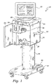
次に、図面を参照し、最初に図1を参照すると、ガス富化流体を調製して送出するシステムが、参照符号10で示されている。システム10を用いると、多種多様な種類のガス富化流体を調製できるが、この特定の実施形態では、システム10は、酸素富化血液を調製する。本明細書に詳細に説明するように、システム10は、血液を患者から抜き取り、血液と酸素過飽和生理的流体を組み合わせ、そして酸素富化血液を患者に送出して戻すようになっている。
システム10を外科処置中に用いることができるので、システム10は、代表的には、通常の手術室環境内に配置されるように寸法決めされている。システム10を手術室内の静止器械又は備品として構成できるが、種々の外科器械が移動式のものであることが望ましい場合が多い。したがって、この実施形態では、システム10は、台座14により転動ベース12に結合された状態で示されている。システム10の電気的及び/又は機械的構成部品のうちの幾つかをベース12または台座14内に収容できるが、これら構成部品は、代表的には、ハウジング16内に配置されることになろう。システム10の動きの方向を定める取っ手18をハウジング16に結合するのがよく、ハウジング16を台座14上で(例えば、図示していないラックピニオン機構により)昇降させるペダル20をベース12に結合するのがよい。
ハウジング16は、ハウジング16の外部の場所に配置されるシステム10の或る構成部品を保護するカバー、例えば、ヒンジ止めドア22を有するのがよい。代表的にはハウジング16の外部上に設けられる構成部品としては、血液ポンプ24、カートリッジ包囲体26及び種々の制御装置28が挙げられる。追加の外部装置としては、ユーザインタフェースパネル30及びディスプレイ32が挙げられる。
[System overview]
Referring now to the drawings and referring first to FIG. 1, a system for preparing and delivering a gas-enriched fluid is indicated by
Because the
The
次に、図2を参照すると、システム10の種々の構成部品を表すブロック図が示されている。適当な引出し管又はドローチューブ34、例えば、カニューレ、カテーテル又は導入器シースが患者38の適当な血管36に挿入される。血液は、血液ポンプシステム24を用いて引出し管34を介し患者38から抜き取られる。具体的に説明すると、血液ポンプシステム24は、ポンプ40、例えば、蠕動ポンプ40が可撓性管34に沿って収縮波を機械的に生じさせると、引出し管34内の流体は矢印42の方向にポンピングされる。以下に詳細に説明するように、血液ポンプシステム24は、フロープローブ48からのフィードバックを受取る流量計46を有している。フロープローブ48は、患者の戻り管50、例えばカニューレ又はカテーテルに結合されている。このフィードバックにより、血液ポンプシステム24は、所望の血液の流れを維持するために蠕動ポンプ40の毎分当たりの回転数(rpm)を調整できる自動体外回路として動作することができる。
引出し管34及び/又は戻り管50は、半選択的(サブセレクティブ)カテーテルであってよい。戻り管50の構成は、ガス富化体液を戻り管50の長さの少なくとも一部にわたってガス飽和又はガス過飽和させることができるという事実に照らして、特に重要な場合がある。したがって、戻り管50は特に、ガスの一部が溶液から出るようにするキャビテーション核の生成を減少させ又は無くすよう設計されるのが一般的である。例えば、カテーテルの長さと内径の比は、酸素添加装置54から患者38までに比較的低い圧力降下を生じさせるよう選択されたものであるのがよい。一般に、カテーテルは、6フレンチ(2ミリメートル)の案内カテーテル内に収まるように寸法決めされている。例えばポリエチレン、PEBAX(ポリエーテルアミド)又はシリコーンのような材料をカテーテルの構成に使用することができる。また、カテーテルの管腔は、キャビテーション核の生成を生じさせる場合がある移行部が比較的無いものであることが必要である。例えば、融着ポリマー移行部の無いスムーズな管腔が、一般的に良好に働く。
Referring now to FIG. 2, a block diagram representing the various components of the
The
血液は、引出し管34を通って酸素添加装置54の中に矢印52の方向に圧送される。種々のタイプの酸素富化装置が患者の体液をその戻り前に酸素添加するのに適しているが、システム10内に設けられる酸素添加装置54は、有利には、酸素過飽和生理的流体を調製し、これを血液と組み合わせて血液を酸素で富化する。また、酸素添加装置54は、有利には、無菌性で、着脱自在で、しかも使い捨てにすることができるので、患者38に対する処置を完了した後、酸素添加装置54を取り外し、別の酸素添加装置54で置き換えて次の患者に用いることができるようになっている。
Blood is pumped through the
以下、酸素添加装置54の利点について詳細に説明する。しかしながら、図2の説明の目的上、この時点においては、生理的流体、例えば食塩水が、システム制御装置又はコントローラ55の制御下で、適当な供給源56、例えばIVバッグから、酸素添加装置54の第1のチャンバ58に送られることを理解すれば十分である。適当なガス、例えば酸素が、供給源60、例えばタンクから酸素添加装置54の第2のチャンバ62に送られる。一般的に言って、第1のチャンバ58からの生理的流体は、第2のチャンバ62内へ圧送され、霧化されて酸素過飽和生理溶液を生じさせる。次いで、この酸素過飽和生理溶液を酸素添加装置54の第3のチャンバ64内へ送り込み、患者38からの血液と一緒にする。患者の血液が酸素過飽和生理溶液と混じり合うと、酸素富化血液が作られる。この酸素富化血液は、戻り管50により酸素添加装置54の第3のチャンバ64から取り出される。
Hereinafter, advantages of the
システム10のホスト/ユーザインタフェース66は、引出し管34に加わる圧力と戻り管50に加わる圧力の両方をそれぞれ、引出し圧力センサ68及び圧力センサ70を介してモニタする。図6に示すように、酸素添加装置54に結合された引出し管34及び戻り管50の端部は、この実施形態ではY−コネクタ71で具体化されている。Y−コネクタ71は、引出し圧力センサ68及び戻り圧力センサ70を有し、これらセンサは、電気コネクタ73を介してホスト/ユーザインタフェース66に作動的に結合されている。ホスト/ユーザインタフェース66は、これら圧力の読みをディスプレイ32に送って、ユーザが圧力をモニタし、必要ならばこれらを調整できるようになっている。また、ホスト/ユーザインタフェース66は、酸素添加装置54の混合チャンバ64内の流体のレベルをモニタするレベルセンサ72からの信号を受取り、酸素過飽和生理流体が気泡生成を殆ど生じさせないで又は全く生じさせないで患者の血液と混じり合うようにする。
システム10は有利には、適当な気泡検出器74を更に有する。気泡検出器74は、気泡が戻り管50を通って患者38に到達するときに気泡を検出するよう戻り管50のところに位置決めされた適当な気泡センサ76を有している。この場合も又、以下に詳細に説明するように、気泡検出器74は、気泡センサ76からの信号を受取り、患者38に戻っている酸素富化液体中で移動している場合がある気泡の性状に関する情報を処理する。この実施形態では、気泡検出器74は、この情報をホスト/ユーザインタフェース66に提供して、流出液中の気泡に関する情報がディスプレイ32を介してユーザに提供されるようになっている。気泡検出器74は又、以下に詳細に説明するように或る環境においてシステム10を制御し又はその運転を停止させる場合がある。
The host /
システム10は、インターロックシステム44を更に有している。インターロックシステム44は、種々の理由でシステム10の構成部品のうちの多くと連絡状態にある。インターロックシステム44は、種々の構成部品をモニタしてシステム10が或る特定の規定された範囲内で動作するようにする。例えば、インターロックシステム44は、圧力センサ68,70からの引出し圧力及び戻り圧力に関する情報、レベルセンサ72からの混合チャンバ64内における流体のレベルに関する情報、及び気泡検出器74からの気泡の数及び/又はサイズに関する情報並びに種々の構成部品の動作状態に関する他の情報を受取る。この情報に基づいて、インターロックシステム44は、もしシステム10が規定された範囲からはみ出て動作し始めるとシステム10の運転を停止させることができる。例えば、インターロックシステム44は、引出し管34及び戻り管50にそれぞれ設けられたクランプ78,80に係合し、血液ポンプシステム24及び酸素添加装置54を制御するシステムコントローラ55を働かなくさせることができる。インターロックシステム44は、代表的には、自動方式で動作するが、安全スイッチ82を設けて、たとえシステム10がその規定範囲内で作動していても、ユーザがシステム10の運転の停止を同一のやり方で開始させることができるようにしてもよい。
The
システム10は、従来型体外回路に対し代表的には25〜100ミリリットルの範囲の小さい準備容積即ちプライム容積しか有していない。かくして、システム10にはヒータが用いられないのが一般的である。しかしながら、引出し管34内の流入血液又は戻り管50内の流出ガス富化血液の温度を制御することが望ましい場合、適当な装置、例えば、熱交換器を管34,50のうち一方又はこれら両方に作動的に結合するのがよい。当然のことながら、流体がシステム10を通って移動しているときに、流体を暖めるために熱交換器(図示せず)を用いることができるだけでなく、この熱交換器は又、流体を冷却するために用いることができる。約30℃〜34℃における中度の低体温症が例えば心筋梗塞における虚血性損傷を遅延させることが判明しているので、流体を冷却することが望ましい場合がある。
〔ホスト/ユーザインタフェース〕
図1及び図2を参照して上述したシステム10の種々の細部について他の図を参照して説明する。今、図3を参照すると、ホスト/ユーザインタフェース66の例示の実施形態が示されている。ホスト/ユーザインタフェース66は、ユーザインタフェース84及びホストインタフェース85を有している。ユーザインタフェース84は、ユーザ入力及びディスプレイ装置、例えば、タッチスクリーンディスプレイ86を有するのがよい。図4に示すように、タッチスクリーンディスプレイ86は、「ボタン」87を有するのがよく、これらボタンは、ユーザがこれらに触ると或る特定の動作を開始させる。タッチスクリーンディスプレイ86は、例えば、警報/メッセージのような情報88、状態指示器89、血液流に関する情報90及び気泡の数91を更に含むのがよい。
ユーザ入力の取扱いは、タッチスクリーンドライバ92で行われ、表示される情報は、ディスプレイドライバ93によって取り扱われる。タッチスクリーンドライバ92は、ユーザ入力をインタフェース、例えば、RS−232インタフェース94に送る。RS−232インタフェース94は、これらユーザ入力をシステム10の他の部分、例えば、システムコントローラ55、インターロックシステム44、血液ポンプシステム24及び気泡検出器74に伝送することができる。ディスプレイドライバ93は、ディスプレイコントローラ95と連絡状態にあり、このディスプレイコントローラも又、バス96を介してRS−232インタフェース94に結合されている。ディスプレイコントローラ95は、システム10の種々の他の部分から更新された情報を受取り、この情報を用いてディスプレイ86を更新する。
[Host / User interface]
Various details of the
The user input is handled by the touch screen driver 92, and displayed information is handled by the
ホストインタフェース85は、種々の他の機能を更に有するのがよい。例えば、ホストインタフェース85は、ユーザインタフェース84上に設けられたスピーカ98を駆動するサウンドカード97を有するのがよい。加えて、ネットワークアダプタ99の利用により、ホストインタフェース85は、外部ネットワーク、例えば、病院内に構築されたLAN又はシステム10のための交信を可能にする遠隔ネットワーク、例えば、インターネットと情報のやり取りをすることができる。最後に、ホストインタフェース85は、アナログ及び/又はディジタルi/o装置101を有するのがよく、このi/o装置は、この例では、或る特定の信号、例えば、イネーブル信号、「停止要求」信号、引出し圧力信号、及び戻り圧力信号を送受信する。
The
〔血液ポンプシステム及びインターロックシステム〕
以下に説明する構成部品のうち多くは、特に例示のシステム10において有用であるが、他形式のシステムにも極めて有用である。例えば、図5を参照して詳細に説明する血液ポンプシステム24は、システム10と関連して用いられるだけでなく、他形式の灌流システム、例えば、従来型心肺器械及び他形式の他の体外回路にも利用できる。上述したように、血液ポンプシステム24は、患者38から引出し管34を通って血液を引き出す適当なポンプ40、例えば、蠕動ポンプを利用する。血液ポンプシステム24は、ライン100,102を介して流量変換器48と連絡状態にある流量計46、例えば、遷音速流量計を更に有する。流量変換器48からのフィードバックにより、血液ポンプシステム24は所望の流量を維持することができる。ユーザ、例えば、灌流技術者又は看護士は、所望の流量を制御パネル30を介して入力することが可能である。この例では、制御パネル30は、現在の血液流量を1分間当たりのミリリットルの単位で指示する手段、及びユーザが血液の流量を増大させるように調節する「アップ(up)」ボタン104及び減少させるように調節する「ダウン(down)」ボタン106を有している。制御パネル30は、「プライム(prime)」ボタン108、「始動(start)」ボタン110及び「停止(stop)」ボタン112を更に有している。加えて、制御パネル30をフットスイッチ114によって補うことができ、このフットスイッチは、停止ボタン112と同一の機能を実行する停止ペダル116と、プライムボタン108及び始動ボタン110と同一の機能を実行するプライム始動ペダル118とを有している。
[Blood pump system and interlock system]
Many of the components described below are particularly useful in the
血液ポンプシステム24は、首尾一貫した流量をもたらすやり方でポンプ40の毎分当たりの回転数(rpm)を維持したり調整したりするために流量変換器48からのフィードバックを利用するので、血液ポンプシステム24は、システムがいったん始動され、流量が設定されると、ユーザとの対話を必要としない。したがって、他の体外回路で用いられる血液ポンプとは異なり、血液ポンプシステム24を、高い技術を持つ灌流技術者ではなく、半人前の技術者又は看護士により作動させることができる。
かかる半人前の操作でも極めて高い信頼度を得るために、血液ポンプシステム24は、インターロックシステム44によって提供される或る特定の特徴を利用する。例えば、図6にも示すインターロックシステム44を参照すると、インターロックシステム44は、パーソナリティモジュール120を有し、或いは、これにアクセスすることができる。パーソナリティモジュール120は、メモリ122、例えば、読出し専用メモリを有するのがよい。パーソナリティモジュール120のメモリ122は、種々の情報、例えば、流量及び流量範囲並びに後で説明する情報を含むのがよい。したがって、特定の患者について又は特定のタイプの患者について所望の流量及び(又は)所望の流量範囲をメモリ122中にプログラムするのがよい。例えば、急性心筋梗塞用途では、流量は、75ミリリットル/分であり、発作用途については、流量は、300ミリリットル/分であるのがよい。この例示の実施形態では、パーソナリティモジュール120をY−コネクタ71内に設けるのがよい。パーソナリティモジュール120内へプログラムされた情報は特定の患者又は特定のタイプの患者に関連しており、しかも、新たなY−コネクタ71が各患者に用いられるのが通例なので、Y−コネクタ71内のパーソナリティモジュール120の配置場所は、治療を受けている各患者でシステム10をカスタマイズする効率的な方法を提供する。
The
In order to obtain extremely high reliability in such half-person operation,
インターロックシステム44は、この流れ情報をメモリ122から読み取ってこれをライン124の流量計46によって送られた流量と比較する。流量計46からの流量が所望流量に又はメモリ122内へプログラムされている所望の流量範囲内に維持されている限り、インターロックシステム44は、ライン126上の作動可能信号即ちイネーブル信号を血液ポンプシステム24に送り続けることになる。しかしながら、もし流量がオペレータの介入、流量変換器48の故障などに起因して所望範囲から外れると、インターロックシステム44は、ライン126上の信号を切り換えて血液ポンプシステム24を作動不能にさせる。インターロックシステム44は、患者38の安全のためにシステム10の運転を停止させるため、更に、クランプ78,80を作動させることになる。
インターロックシステム44は、ライン124の流量計46からのアナログ流量信号を受取ってこれを調整するアナログ調整回路130を有している。この調節された信号は、比較器及び閾値設定装置132を用いてメモリ122からの情報と比較する。この比較結果は、論理ブロック即ちロジックブロック134に送られ、このロジックブロックは、現場でプログラム可能なゲートアレイ(FPGA)又は複素プログラム可能ロジック装置(CPLD)であるのがよい。ロジックブロック134は、ライン126上にイネーブル信号又は作動不能信号を発生させる。
調整回路130は更に、引出し圧力変換器68及び戻り圧力変換器70からアナログ圧力信号を受取る。これら圧力をモニタすることにより、引出し管34も戻り管50もよじれないこと、または、引出し管34も戻り管50も流体を最小の所望圧力又はこれよりも高い圧力で送出させることを可能にすることを確保する。ロジックブロック134は、これらの圧力を最小圧力設定値、例えば、−300mmHgと比較して、もし圧力が最小圧力設定値を下回れば、警告信号を出す。加えて、引出し圧力をモニタして引出し圧力が最小引出し圧力閾値、例えば、−300mmHgよりも高い状態を保って、気泡が血液ポンプ40によって溶液から引き出されないようにする。さらに、戻り圧力をモニタして戻り圧力が最高戻り圧力、例えば、2000mmHgを超えないようにする。
インターロックシステム44がシステム10の種々の他の部分とどのように連係するかについては、必要に応じて後で説明する。しかしながら、血液ポンプシステム24とインターロックシステム44は、血液を患者から所望の且つ維持可能な流量で抜き取る技術を提供し、所望の流量からの偏差により、システムが患者38にとっての安全な方法で作動停止するようにすることが理解できる。したがって、大抵の場合、灌流技術者は不要になる。
The
How the
〔酸素添加装置〕
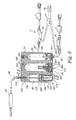
血液ポンプシステム24を多種多様なシステムに用いることができるが、本発明の説明の主な目的上、これはシステム10内に組み込まれる。図2を参照して上述したように、その主な目的のうちの1つは、血液を酸素添加装置54に送ることである。したがって、血液ポンプシステム24又は他の構成部品を更に詳しく説明する前に、酸素添加装置54の機能の仕方について理解するのがよい。
最初に、図7、図8及び図9を参照すると、酸素添加装置54の例示の実施形態が示されている。上述したように、酸素添加装置54は、3つのチャンバ、即ち、流体供給チャンバ58、霧化チャンバ62及び混合チャンバ64を有している。一般的に言って、生理的流体、例えば食塩水が流体供給チャンバ58に引き入れられる。生理的流体は、圧力下で流体供給チャンバ58から霧化チャンバ62に移送される。霧化チャンバ62内では、生理的流体はガス、例えば、酸素で富化され、ガス富化生理的流体を形成する。例えば、生理的流体をガスで過飽和するのがよい。ガス富化生理的流体を混合チャンバ64に移して体液、例えば、血液と混合する。ガス富化生理的流体と体液の混合により、ガス富化体液が生じる。一例では、患者からの血液は、酸素過飽和食塩水と混合されて、患者に戻される。
[Oxygenator]
Although the
Initially, referring to FIGS. 7, 8 and 9, an exemplary embodiment of an
流体供給チャンバ58についての詳細な説明から始めると、適当な送出装置、例えば、管140を生理的流体の供給源に結合されている。この例では、管140は、滴下チャンバ141を含み、管140の一端がIVバッグ56に結合されている。管140の他端は、ノズル142に結合されている。ノズル142は、流体供給チャンバ58に通じる流体通路144の一部を形成する。逆止弁146が、流体通路144内に設けられていて、流体が流体通路144を通って流体チャンバ58に流入するが、流体通路144を通って流出することができないようになっている。
図10の詳細図に示すように、逆止弁146は、流体通路144内に設けられたリップとノズル142との間に位置するOリングシール148を有している。ばね150がボール152を押圧してこれをOリングシール148に接触させている。矢印154の方向に流れる流体がばね150の力及び流体供給チャンバ58内の圧力に打ち勝つと、ボール152は、ばね150に抗して押されて流体が流体供給チャンバ58に流入することができるようになる。しかしながら、ボール152がOリングシール148を効果的に封止しているので、流体は逆方向には流れることはできない。
Beginning with a detailed description of
As shown in the detailed view of FIG. 10, the
ピストン組立体160が、流体供給チャンバ58の反対側の端部に設けられている。ピストン組立体160は、流体供給チャンバ58内に固定的に設けられたスリーブ162を有している。図11に詳細に示すように、プランジャ164が、スリーブ162内に摺動自在に設けられている。キャップ166が、プランジャ164の一端部のところに設けられている。キャップは、フランジ168を有し、このフランジは、ピストン組立体160の下方運動を制限するようスリーブ162の内径よりも大きな外径を有している。スリーブ162、プランジャ164及びキャップ166が比較的剛性の材料、例えばプラスチックで作られることが有利であるが、キャップ166には、比較的弾性のエンドピース170が設けられている。エンドピース170は、有利には、流体供給チャンバ58の内壁に密着する密封部材172を有する。
図11に想像線で示すように、ピストン組立体160は、第1の位置(実線で示されている)と第2の位置(想像線で示されている)との間で動くことができる。この運動を容易にするため、後で説明する装置がピストン組立体160の自由端部174に結合されている。かかる結合は種々の適当な仕方で行われるが、この例では、キー176がピストン組立体160の自由端部174に設けられる。キー176は、幅の狭い部分178及び比較的幅の広い部分180を有し、このキーは、ドアのノブに幾分似ていて、かくして、装置がピストン組立体160にラッチ止めしてピストン組立体を第1の位置と第2の位置との間で動かすことができるようになっている。
A
As shown in phantom in FIG. 11, the
この説明全体の完全な検討から理解されるように、本明細書に開示した特定の酸素添加装置54の主要な利点のうちの1つは、無菌性であること及び使い捨てであることが挙げられる。ピストン組立体160の無菌性は、無菌性シース182をキャップ166とスリーブ162との間に設けることにより容易に達成できる。この実施形態では、無菌性シース182は、クランプ186によりキャップ186に結合されると共にクランプ188によりスリーブ162の外側部分に結合された伸長可能な管184を有する。伸長可能な管184は、種々の形態を取ることができ、例えば、ピストン組立体160がその引込み位置(実線で示されている)にあるとき、アコーディオンのような仕方で折り畳まれるプラスチックチューブである。しかしながら、伸長可能な管184は、種々の他の形態を取ることができ、例えば、ピストン組立体160の引込み位置と伸長位置との間で延伸するフレキシブル部材であっても良い。クランプ186,188も又、種々の適当な形態を取ることができ、この例では例えばゴム製Oリングである。
As will be understood from a thorough review of this entire description, one of the major advantages of the
さらに、図12を参照すると、流体供給チャンバ58は、第2の流体通路190を更に有している。この実施形態の特定の例で示すように、流体通路190は、管196により流体通路194に結合されている。通路194は、弁組立体200の入口手段であり、この弁組立体は、流体供給チャンバ58からの流体を霧化チャンバ62内へ送り込む仕方を制御する。
作用を説明すると、流体供給チャンバ58内のピストン組立体160は、ピストンポンプとして働く。ピストン組立体160が引っ込むと、流体が流体供給源56からチャンバ58内に引き込まれる。通路190から引き出される流体は存在しない。というのは、弁組立体200が閉じられていて、逆止弁192がこの方向に閉じられているからである。ピストン組立体160が伸長すると、チャンバ58内の流体は、代表的には約670psi(4.62MPa)まで加圧され、そして流体通路190を通って流体供給チャンバ58から追い出される。流体供給チャンバ58の出口は、適当な流体通路を介して霧化チャンバ62の入口に結合されている。
Still referring to FIG. 12, the
In operation, the
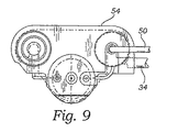
弁組立体200の詳細図が、図13及び図14に示されている。弁組立体200は、3つの弁、即ち、充填弁202、フラッシュ弁204及び流れ弁(フローバルブ)206を有している。任意適当な弁構造及び任意適当なタイプの弁を使用できるが、この実施形態では、弁202,204,206は、常態では図示のように閉鎖位置に付勢されているニードル弁である。霧化チャンバ62内の圧力が或る特定のレベル、例えば、約100psi(0.689MPa)を超えて上昇すると、弁202,204,206は、閉鎖位置から開放位置に動くようになっていると仮定すれば、そのようになる。この実施形態では、以下に詳細に説明するように、弁202,204,206のうちの1以上が開くようになるまで、プッシュピン及び関連の作動機構(図13に想像線で示されている)が弁202,204,206を閉鎖位置に維持する。
ガス、例えば、酸素を圧力下で通路210を介して霧化チャンバ62に送る。例えば、酸素タンク60を通路210の入口に結合して所望のガス供給源とするのがよい。弁202,204,206が全て閉じられている場合、流体は、入口通路194から充填弁202が設けられている通路212内へ流れる。通路212の断面積は充填弁202の断面積よりも大きいので、流体は、閉鎖状態の充填弁202の周りを流れて霧化器(アトマイザ)216に通じる通路214に流れる。
Detailed views of the
A gas, such as oxygen, is sent under pressure to the
霧化器216は、一方向弁220が設けられた中央通路218を有している。この実施形態では、一方向弁220は、図10を参照して説明したものと類似した逆止弁である。したがって、流体圧力が一方向弁220内のばねの力に打ち勝つと共に、霧化チャンバ62内のガスの圧力に打ち勝つと、流体は、通路218を通って流れ、霧化器216の端部のところで出口222から押し出される。
ノズル222は、流体小滴を形成し、流体小滴が霧化チャンバ62内で移動するとき、流体小滴内に霧化チャンバ62内の酸素が拡散する。この酸素富化流体を、本明細書においては、水性酸素(AO)という場合がある。この実施形態では、ノズル222は、角度αで構成された小滴円錐を形成し、この角度は代表的には、霧化チャンバ62内における通常の動作圧力、例えば、約600psi(4.137MPa)では、約20゜〜40゜である。ノズル222は、直径が約0.004インチ〜0.005インチ(0.10ミリメートル〜0.13ミリメートル)の流体オリフィスを含むシンプレックスタイプのスワール式加圧霧化器ノズルである。酸素が注入された小滴が霧化チャンバ62の底部のところのプール内に落下することを理解すべきである。プールのレベルがノズル222のレベルよりも高い場合、霧化器216が正しく霧化を行わないので、プールのレベルは、霧化器216が絶えず正しく機能するように制御される。
The
The
酸素は、非霧化形態で霧化チャンバ62に送られた流体よりも非常に高い程度まで霧化状態の流体内に溶解する。上述したように、霧化チャンバは、代表的には、約600psi(4.137MPa)の一定圧力で動作する。霧化チャンバ62を600psi(4.137MPa)で又は200psi(1.379MPa)よりも高い任意の圧力で動作させると、200psi(1.379MPa)以下の圧力で動作する場合よりも、霧化器216からの生理的溶液のより微小な液滴の生成を促進し、生理的流体中のガスのより良好な飽和効率を促進させることが有利である。簡単に説明すると、霧化チャンバ62内で生じた酸素過飽和流体は、混合チャンバ64に送られ、ここで患者38からの血液と組み合わされる。患者の血液を酸素で富化する度合いを制御すると共にシステム10を一定の血液流量で作動させることが望ましいので、霧化チャンバ62内の酸素過飽和流体を稀釈してその酸素含有量を減少させることが望ましい場合がある。かかる稀釈が望ましい場合、充填弁202を開いて、霧化器216を通る経路と比較して比較的低い抵抗の流体用経路を生じさせる。したがって、流体は、霧化器216を通るのではなく、管232を介して霧化チャンバ62内へ上方に延びる通路230を通って流れる。管232は、有利には、霧化チャンバ62の円筒壁に対し幾分接線方向に傾斜していて、流体が霧化チャンバ62の底部のところのプール内の酸素過飽和流体と容易に混合するようになっている。
Oxygen dissolves in the atomized fluid to a much higher degree than the fluid sent to the
弁組立体200は本質的に、2つの更に別の機能を実行する。第1に、充填弁202及び流れ弁206を閉鎖した状態で、フラッシュ弁204を開いて、流体が入口通路194から通路212,214を通って通路240,242内へ流れるようにすることができ、通路242の断面積は、流れ弁206の断面積よりも大きい。かくして、流体は、毛管246に結合された出口通路244から流出する。毛管246は、混合チャンバ64内へ上方に延びる先端部248で終端している。この流体はガス富化されていないので、この流体は、本質的には、通路242,244及び毛管246をフラッシングして汚染要因物を取り除くと共に適当な流体の流れを確保するのに役立つ。第2に、ガス過飽和流体を霧化チャンバ62の底部のところのプールから混合チャンバ64内へ送り込むことが望ましい場合、充填弁202及びフラッシュ弁204を閉じた状態で、流れ弁206を開くのがよい。
この第2の状況では、霧化チャンバ62内の圧力が比較的高く、例えば、約600psi(4.137MPa)であり、混合チャンバ64内の圧力が比較的低く、例えば、約30psi(0.207MPa)であるという事実により、ガス過飽和流体は、霧化チャンバ62から毛管246を通って混合チャンバ64内に容易に流れる。毛管先端部248の端部は有利には、混合チャンバ64の血液入口250の下に位置決めされている。この空間的な配置状態により、一般に、引出し管34を通って血液入口250に流入する血液は、毛管先端部248を通って混合チャンバ64に流入する酸素過飽和流体と効果的に混じり合うようになる。最後に、血液ポンプシステム24の力により、酸素添加された血液は、出口252を通って混合チャンバ64から戻り管50内へ圧送される。
The
In this second situation, the pressure in the
代表的には、毛管246及び毛管先端部248は、適当な抵抗が維持されて酸素過飽和流体が霧化チャンバ62から混合チャンバ64内へ流れるときに酸素過飽和流体内の酸素が溶液中に存在したままであるように比較的長い。例えば、毛管246及び毛管先端部248は、内径が50ミクロン〜300ミクロンであり、長さが3インチ〜20インチ(7.62センチメートル〜50.8センチメートル)であるのがよい。したがって、酸素添加装置54のコンパクトなサイズを維持するため、毛管246は、図15の詳細図に示すように、混合チャンバ64の出口ノズル252に巻き付けられる。コイル状毛管246を損傷から保護するため、保護シールド254が、有利には、コンパートメント256を形成するようコイル状毛管246の周りに形成されている。
霧化チャンバ62と混合チャンバ64の両方は、それぞれ、通気弁258,260を有している。通気弁258,260は、図16の詳細図に示すように、ガス圧力を酸素添加装置54から大気中へ抜くことができる一方向弁である。この特定の実施形態では、通気弁258,260は、ばね266により閉鎖位置においてOリングシール264に押し付けられるプランジャ262を有している。付勢力は、プランジャ262をシール264から遠ざけてチャンバを通気させるのにチャンバ62又は64内に1〜2psi(0.0069〜0.0138MPa)が存在すれば十分であるように小さい。したがって、以下に詳細に説明するように、カートリッジ包囲体26の一部をなし、システムコントローラ55によって制御される作動装置は、常態では、弁258,260を閉鎖位置に維持する。
Typically, the capillary 246 and the
Both the
システム10の残部の説明を始める前に、一般的には血液の酸素添加に関するいくつかの特徴及び特に開示した酸素添加装置54の使用法に注目すべきである。第1に、血液に酸素を添加する種々の方法が公知であり又は開発中である。霧化チャンバは比較的短期間で比較的大量のガスを流体中に拡散させる便利なメカニズムを提供するが、ガスを流体内に溶解させる唯一の方法ではない。確かに、他の装置、例えば、メンブレン酸素添加装置、ガススパージャ、バブラ及び薄膜酸素添加装置を用いてもこの機能を同様に果たすことができる。第2に、ピストンポンプも同様に流体を酸素添加装置、例えば、霧化器に送る前に流体を加圧する簡単で且つ効率的な方法を提供するが、他形式のポンプ又は加圧方法も使用できる。第3に、混合チャンバはガス過飽和流体と血液の混合状態が適当にモニタされて制御されるコンパクトな環境を提供するが、ガス富化流体を他の方法で血液と混合させてもよい。例えば、ガス過飽和流体をカテーテル又は他の適当な器具の混合ゾーン内で血液と混合させてもよい。したがって、ピストンポンプ、霧化器及び混合チャンバはシステム10の例示の実施形態で利用される酸素添加装置54を構成するが、或る特定の認識されている利点により、他の装置が、一般的に言って、これらの機能を実行しても良い。
Before beginning to describe the rest of the
これらの一般性を考慮して、本明細書において開示される酸素添加装置54は、これを医用環境内で用いるのに特に魅力あるものにする幾つかの利点をもたらす。第1に、酸素添加装置54は有利には、高強度低コストの器具をもたらすように成形可能な透明なプラスチック、例えば、ポリカーボネートで作られる。第2に、酸素添加装置54は、比較的コンパクトであり、例示の試料を測定して高さが約12センチメートル、幅が10センチメートル、深さが5.5センチメートルである。かくして、これは、システム10が固定されているか、或いは動くことができるかどうかにはかかわらず、手術室又は特定の処置ラボ内に容易に適合するシステム10内に利用できる。第3に、酸素添加装置54は、酸素富化流体の調製と、酸素富化流体と血液の混合を組み合わせて、4つだけの関連部、即ち、(1)流体供給、(2)酸素供給、(3)血液供給、(4)血液戻りを利用した一体装置にする。他の関連部は、酸素添加装置54それ自体の一部であり、これら連結部は、ユーザからの追加の連結を必要としない。第4に、酸素添加装置54を作動させるのに用いられる弁は全て、その一体構造内に組み込まれている。かくして、弁及びこれらと関連した流体通路は、外部汚染から保護され、ユーザは、種々の流体の使用から生じる汚染に対して保護される。その結果、酸素添加装置54は、外科処置中、患者に対して使用され、次に、取り外され、そして次の患者に対する外科処置を行う前に交換できる比較的汚染の無いカートリッジである。
In view of these generalities, the
〔カートリッジ包囲体〕
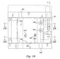
電気的構成部品の残部及びこれらがシステム10の種々の機械的構成部品を制御する仕方を説明する前に、或る特定の機械的構成部品と酸素添加装置54との間のインタフェースを構成する方法について以下に説明する。上述したように、酸素添加装置54は、カートリッジ包囲体26の内側に配置される。図17は、カートリッジ包囲体26の分解図であり、図18は、カートリッジ包囲体26の正面図である。この実施形態では、カートリッジ包囲体26は、ヒンジ止めドア304が出入口になるカートリッジ受け部302を有している。酸素添加装置54をカートリッジ受け部302内に配置したとき、ドア304を閉じ、それを種々の理由でラッチ止めする。第1に、カートリッジ受け部302及び酸素添加装置54は、種々の表面、通気孔、弁等が所望の仕方で位置決めされるように相補的な仕方で寸法決め及び形状決めされている。ドア304を閉じてラッチ止めすると、ドア304の内面306は、有利には、酸素添加装置54の表面308に圧接して、酸素添加装置54の位置決めが正確になるようにする。第2に、ドア304は、有利には、システム10の通常の作動中、酸素添加装置54の取り外しを防止するよう施錠される。したがって、ドア304は、ラッチ310を備えている。図19〜図26を参照すると、ドアラッチ310は、取っ手部分312及びラッチ止め部分314を有している。
[Cartridge enclosure]
Before describing the remainder of the electrical components and how they control the various mechanical components of the
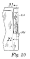
ドア304をラッチ止めするため、ユーザは、取っ手部分312を掴んでラッチ310を全体として矢印318の方向にピボットピン316の周りに回動させる。ラッチ310が矢印318の方向に回動すると、ラッチ止め部分314はラッチピン320の周りに引っ掛かる。ラッチピン320は、付勢機構322に結合されている。付勢機構322は、この実施形態では、壁328に設けられた穴を貫通した2本のピン324,326を有している。各ピン324,326の周りにはそれぞればね330,332が設けられていて、ラッチピン320を壁328に向かって付勢している。ラッチ止め部分314がラッチピン320の周りに引っ掛かると、ラッチ310は、ばね330,332の付勢力に打ち勝ってラッチ止め機構322を矢印334の方向に僅かに動かすのに役立つ。しかしながら、ラッチ止め機構322は、その付勢力に起因して、ラッチ310及びかくしてドア304を定位置にしっかりと保持するのに役立つ。
ラッチ310を適所に保ち、かくしてドア304を施錠するため、ロック機構340が設けられている。この実施形態では、ロック機構340は、壁328の一部に設けられた摺動自在なピン342を有している。ラッチ310が矢印318の方向に動くと、ラッチは最終的に、ピン342の前方端部に接触し、かくして、これを矢印344の方向に動かす。ピン342の後方部分は、引き型即ちプルタイプのソレノイド348のピストン346に結合されている。ピストン346は、ばね350によって外方に付勢されて、ピストン346は、通常、伸長位置にあるようになっている。
To latch
A
ラッチ310は、これがラッチ止め位置に達すると、ばね350がピン342を矢印352の方向に押してピン342がラッチ310の一部354上を延びるように構成されている。ピン342がラッチ310の一部354上のそのロック位置にある状態では、ラッチ止め部分314をラッチ止め機構322から取り外すことができない。その代わり、ラッチ310は、ソレノイド348のピストン346がピン342をラッチ310から遠ざけるまでロック状態のままである。
また、ラッチ310がそのロック位置にあるかどうかを指示する電気信号を出力するセンサ360を有していることに注目すべきである。この実施形態では、センサ360は、ホール効果センサである。ラッチ310は、ラッチ310がロック位置にあるとき、センサ360と整列するよう位置決めされた磁石362を有している。磁石362がセンサ360と整列すると、電磁信号が遮断されない。しかしながら、磁石362が整列状態に達するまで、センサ360からの電磁信号は遮断され、かくして、ラッチ310が依然としてそのロック位置には無いことが分かる。
The
It should also be noted that it has a
〔弁作動〕
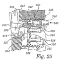
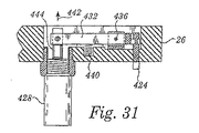
上述したように、この実施形態では、酸素添加装置54の寸法形状、カートリッジ受け部302の輪郭及びドア304の閉鎖状態は、酸素添加装置54がカートリッジ包囲体26内に所望の仕方で位置決めされるようにする。正しい位置決めは、酸素添加装置54の弁及びベントの配置及びこれらの制御及び作動の仕方に起因して関心があるものである。上述したように、酸素添加装置54の弁及び通気孔は、この実施形態ではピンを用いて作動が行われる。酸素添加装置54の頂部は、通気孔258,260を有し、酸素添加装置54の底部は、3つの弁202,204,206を有している。この実施形態では、これらの通気孔258,260及び弁202,204,206は、ソレノイド作動ピンを用いて電気機械的に作動される。
これら作動装置の詳細図を図27〜図32に示す。最初に、図27を参照すると、カートリッジ包囲体26の底面図が示されている。酸素添加装置54は想像線で示されている。カートリッジ包囲体26の底部は、有利には、酸素添加装置54の血液戻り管50を挿通させたスロット380を有することに注目すべきである。酸素添加装置54をカートリッジ包囲体26内の定位置にいったん配置させると、充填弁202,フラッシュ弁204及びフロー弁206は、それぞれ作動ピン382,384,386と整列関係をなすべきである。有利には、ピン382,384,386は各々、端部のところがテーパしていて位置合わせ不良のための許容度を高めている。作動ピン382,384,386は各々、それぞれのソレノイド388,390,392によって閉鎖位置と開放位置との間で動く。ソレノイド388,390,392はそれぞれ、レバー394,396,398を介して、作動ピン382,384,386に結合されている。レバー394,396,398はそれぞれ、支点又はピボットピン400,402,404を中心として回動する。
(Valve operation)
As described above, in this embodiment, the size and shape of the
Detailed views of these actuators are shown in FIGS. First, referring to FIG. 27, a bottom view of the
アクチュエータの動作の仕方は、図28及び図29を参照すると理解できる。これらの図はフラッシュ弁204のためのアクチュエータだけを示しているが、他のアクチュエータは、これと同一の仕方で充填弁202及びフロー弁206を作動させることを理解すべきである。上述したように、弁202,204,206は、常態では閉鎖位置に保持されている。したがって、この特定の実施形態では、ソレノイド388,390,392は、引き型即ちプルタイプのソレノイドである。図28に示すように、プルタイプソレノイド390のピストン406は、ばね408によって伸長位置に押圧され、このばねは、レバー396の一端部を全体として矢印410の方向に付勢する。その結果、ばね408は又、作動ピン384を全体として矢印412の方向に付勢して、フラッシュ弁204をその閉鎖位置に維持する。
フラッシュ弁204が開くことができるようにするためには、ソレノイド390を図29に示すように作動させる。プルタイプソレノイド390の作動により、ピストン406は全体として矢印414の方向に動いて引込み位置に達する。ソレノイド390の力は、ばね408の付勢力に打ち勝って、作動ピン384を全体として矢印416の方向に動かす。作動ピン384が引込み位置にある状態で、フラッシュ弁204は、矢印416の方向に動くことにより開くことができる。
The manner of operation of the actuator can be understood with reference to FIGS. Although these figures show only the actuator for
In order to allow the
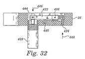
通気弁258,260の作動は、上述したのと同様の仕方で起こる。今、図30を参照すると、カートリッジ包囲体26の平面図が示されている。カートリッジ包囲体26の頂部は、IVチューブ140を挿通させるスロット420を更に有している。酸素添加装置54がカートリッジ包囲体26内にいったん正しく位置決めされると、通気弁258,260は、それぞれ作動ピン422,424と整列する。ピン422,424も又有利には、端部がテーパしていて位置合わせ不良許容度を高めている。作動ピン422,424は、各々、それぞれのソレノイド426,428によって作動される。ソレノイド426,428はそれぞれ、レバー430,432によって作動ピン422,424に結合されている。レバー430,432はそれぞれ、支点又はピボットピン434,436を中心として回動する。
図31及び図32を参照して説明したように、通気弁258,260のアクチュエータの作動は、弁202,204,206のアクチュエータの作動と類似している。図31及び図32は、通気弁260のアクチュエータのみを示しているが、通気弁258のアクチュエータは同様な仕方で動作することを理解すべきである。最初に、図31を参照すると、ソレノイド428はこの実施形態では、プルタイプソレノイドである。ばね440がレバーアーム432を全体として矢印442の方向に付勢してソレノイド428のピストン444を伸長位置に動かしている。したがって、ピボットピン436周りのレバー432の作用により、ばね440は、作動ピン424を伸長位置に動かす。伸長位置では、作動ピン424は、圧力を通気弁260(図示せず)に及ぼして通気弁260を閉鎖位置に維持する。
通気弁258,260を開くためには、ソレノイド426,428を作動させる。図32に示すように、プルタイプソレノイド428を作動させると、ピストン444は、全体的に矢印446の方向で引込み位置に動く。ソレノイド428の力は、ばね440及びかくしてレバー432の付勢力に打ち勝ち、作動ピン424を全体として矢印448の方向に動かして引込み位置に至らせる。作動ピン424が引込み位置にあるとき、通気弁260は、上方に動いて開き、混合チャンバ64内のガスを抜くことができる。
The operation of the
As described with reference to FIGS. 31 and 32, the operation of the actuators of the
In order to open the
〔カートリッジセンサ〕
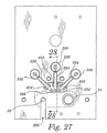
再び図18を参照して、カートリッジ受け部302を検討すると、概略的にはシステム10を、特に酸素添加装置54をモニタし且つ/又は制御するために、多数のセンサが利用されていることが分かる。集めるべき情報の性質及びこの情報を集めるために用いられるセンサのタイプに起因して、酸素添加装置54及びセンサは、かかる情報をより正確且つしっかりと集めやすくする或る特徴を有している。しかしながら、他形式のセンサ及び/又は特徴を利用しても、システム10及び酸素添加装置54のモニタ及び/又は制御に用いられる上記と類似した適当な情報を集めることができるということを理解すべきである。
システム10の電子制御についての詳細な説明から理解されるように、霧化チャンバ62及び混合チャンバ64内の流体レベルをモニタして制御することが望ましい。したがって、霧化チャンバ62内の酸素水のレベルをモニタするためにAOレベルセンサ480が設けられ、混合チャンバ64内の酸素富化血液のレベルをモニタするためにハイレベルセンサ482及びローレベルセンサ484が設けられている。上述したように、酸素添加装置54は、この例示の実施形態では、交換可能なカートリッジとして構成されているので、これらセンサは、酸素添加装置54内ではなく、カートリッジ包囲体26内に配置されている。かくして、レベルセンサ480,482,484は、チャンバ62,64内の流体に実際には接触しない。センサ480,482,484が液体に接触すると、これらセンサは汚染状態になり、かくして、一般的には、センサは、システム10を違う患者に用いる度に交換される。これは、恐らくは、交換用品のコストを増大させ、システムの滅菌性に潜在的に悪影響を及ぼすので、ユーザの観点と患者の観点の両方から、センサは、酸素添加装置54内の液体に接触しないことが望ましい。
この実施形態では、センサ480,482,484は、超音波センサである。超音波は空気中よりも固体及び液体中で効率的に伝搬するので、センサ480,482,484及び/又は酸素添加装置54を超音波の効率的な送受信を促進する仕方で構成することが望ましい。この実施形態では、センサ480,482,484と酸素添加装置54の両方は、この点に関し有利であることが判明している特徴を有している。
[Cartridge sensor]
Referring again to FIG. 18 and considering the
As will be appreciated from the detailed description of electronic control of the
In this embodiment, the
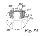
図19及び図33は、高レベルセンサ482及びAOレベルセンサ480をそれぞれ示すカートリッジ包囲体26の断面図である。ローレベルセンサ484は断面で示されていないが、その構造は、センサ480,482の構造と類似しており又は同一である。さらに、センサ482,480の詳細図がそれぞれ、図34及び図35に示されており、この場合も又、センサ480,482,484は、これらの図に示された細部に関し実質的に同一であることが分かる。
酸素添加装置54とセンサ480,482,484相互間の物理的な接触が維持されるようにするため、センサは有利には、付勢されて酸素添加装置54と接触状態をなす。センサ480,482,484は実際に、ばね付勢技術を利用している。ただし、種々の他の形式の付勢技術を利用して同様な結果を達成することができる。この例では、センサ本体494内に形成されたチャネル492内に超音波変換器要素490が設けられている。センサ本体494は、任意適当な形状に形成されたものであってよいが、この実施形態では、円筒形のものとして示されている。センサ本体494は、スリーブ496内に摺動自在に設けられている。スリーブ496は、カートリッジ包囲体26の壁498内に固定的に設けられている。例えば、スリーブ496は、これを壁498に設けられた螺設ボアにねじ込むことができるよう雄ねじ500を有するのがよい。スリーブ496内におけるセンサ本体494の摺動運動を容易にするため、スリーブ496内にブッシュ502を設けるのがよい。この例では、センサ本体494は、センサ本体494の外方運動を制限するために、ブッシュ502の一端部に当接する環状フランジ504を有している。ばね506が、スリーブ496の後方部分内に設けられている。ばね506は、環状フランジ504の反対側の側部に当接してセンサ本体494を全体として矢印508の方向に付勢する。ブッシュ502をスリーブ496にくっつけてもよいし、或いは、その一体部分であってもよいし、このブッシュを外部シール又はキャップ510で定位置に保持してもよい。
19 and 33 are cross-sectional views of the
In order to maintain physical contact between the
センサ480,482,484のばね押し構造によりセンサを付勢して、これらセンサを酸素添加装置54に接触させ、それにより、超音波エネルギの効率的な伝搬を容易にするけれども、センサの端部と酸素添加装置54との接触の性質も効率的な超音波伝搬にとって重要である。それ故、この接触領域を改善するため、センサ480,482,484は、弾性部材512、例えば、ゴムキャップを有している。弾性部材512は、良好な接触が行われるようにするために酸素添加装置54に接触すると僅かに変形することができる。接触領域を一段と良好にするため、酸素添加装置54は有利には、その酸素添加装置54の輪郭が弾性部材512の輪郭と合うように平らな接触部分514,516をそれぞれ有している。加えて、超音波接触領域を更に良好にするため、酸素添加装置54とセンサ480,482,484との間に適当なゲルを用いるのがよい。
Although the
カートリッジ包囲体26は有利には、他のセンサをも有している。例えば、システム10は、酸素添加装置54がカートリッジ包囲体26内に挿入されたかどうかを判定することができることが望ましい場合がある。この情報を提供するため、カートリッジ包囲体26内にカートリッジ存在センサ520を設けるのがよい。この例では、カートリッジ存在センサ520は、図19に示すように、カートリッジ包囲体26の壁498に設けられた開口522内に位置決めされる反射式赤外センサであるのがよい。上述した超音波センサとは異なり、反射式赤外センサの効率は、物理的接触によっては向上しない。確かに、反射式赤外センサの効率は、赤外エネルギを反射させてセンサに戻す表面の性状との関連性が強い。換言すると、表面が凸凹していれば、赤外センサから伝送される赤外エネルギは散乱して反射によりセンサに戻る赤外エネルギが殆ど無くなるか、或いは、全く無い。他方、表面が滑らかであり、全体としてセンサに垂直であり、且つ/又は、反射性であれば、この表面は、反射によりセンサに戻される赤外エネルギの量を最大にするのに役立つ。したがって、カートリッジ存在センサ520に隣接して位置する酸素添加装置54の部分は有利には、カートリッジ存在センサ520に戻す赤外エネルギの反射を促進するよう形作られる。この例では、酸素添加装置54は有利には、カートリッジ存在センサ520が比較的強い反射信号を受取って酸素添加装置54が存在しているかどうかを正しく指示できるように平らな部分524を有する。
The
また、霧化チャンバ62内に生じた酸素水の温度をモニタすることが望ましい場合がある。酸素水の温度は、その酸素添加レベル及び最終的には酸素富化血液の酸素添加レベルが温度と共に変化するので有用なパラメータである。酸素添加装置54及びシステム10の機能をモニタして制御するために温度測定値を考慮に入れることが望ましい場合、温度を、多種多様な領域で検出するのがよい。例えば、酸素を添加すべき生理的溶液が典型的には室温状態にあると仮定すれば、システム10内のどこかに単一の室温センサを設けるのがよい。変形例として、酸素添加装置54内の酸素水が同一の温度状態にあると仮定すれば、酸素添加装置54の温度をモニタしてもよい。
しかしながら、最も高い制御のレベルを提供するため、霧化チャンバ62内の酸素水の温度を測定することが望ましい場合がある。適当な電気接点が酸素添加装置54から延びる状態で熱電対を酸素添加装置54の霧化チャンバ62内に設けてもよいが、使い捨て装置内にセンサを用いると、装置のコストが増大するだけであろう。したがって、霧化チャンバ62の外部に位置し、しかも、霧化チャンバ62内の酸素水の温度をモニタすることが依然として可能であるセンサを利用することが望ましい。この例では、この機能を達成するため、図33に示すように、カートリッジ包囲体26の壁498に設けられた開口542内に外部温度センサ540が結合されている。温度センサ540は、例えば、焦電センサ又は圧電センサであるのがよい。霧化チャンバ62内のAO溶液の温度の変化により、かかる信号の周波数が変化し、かくして、AO溶液の実際の温度が指示される。
It may also be desirable to monitor the temperature of the oxygen water generated in the
However, it may be desirable to measure the temperature of the oxygen water in the
〔ガスカップリング〕
カートリッジ包囲体26は、これが酸素添加装置54と連係する仕方と関連したもう1つの興味ある特徴を更に有している。上述のように、酸素添加装置54は、霧化チャンバ62の頂部の近くに設けられた酸素入口210を有している。また、上述したように、約620psi(4.27MPa)に調整された酸素供給源60が、酸素入口210に結合されている。かくして、かかる圧力を効果的に取り扱い、ユーザの介入を必要としない入口210の連結部を提供することが望ましい場合がある。
図36を参照すると、酸素供給源60は、代表的には、フローバルブ又はフロー弁600によって動作可能になる。フロー弁600は、圧力変換器602及び逆止弁604を通って酸素を送る。酸素は、次に、T継手606を通ってライン608内へ流れる。ライン608は、図37の断面図に示すプランジャ610に結合されている。プランジャ610は、ライン608から側方に延び、次に下方に延びてカートリッジキャビティ302内へ至るポート612を有している。プランジャ610は、ブッシュ又はスリーブ614内に摺動自在に設けられている。図38及び図39の詳細図に最もよく示されているように、スリーブ614は、ばね618が収納された凹部領域616を有している。ばねは、プランジャ610を上方に付勢して、酸素添加装置54の酸素入口210に密着するよう構成されたプランジャ610のカップリング部分620が僅かに凹むようになっている。
プランジャ610の頂部は、ロッド626の傾斜又はカム作用部分624と相補関係をなして当接する傾斜又はカム作用部分622を有している。ロッド626は、カートリッジ包囲体26に設けられた開口部628内に摺動自在に設けられている。ロッド626は、ばね632によって伸長位置で矢印630の方向に付勢されている。図39に最もよく示されているように、ユーザがドア304を閉めると、ロッド626は、ばね632の付勢力に抗して矢印634の方向に動く。ロッド626が戻ってばね632に当接すると、カム作用面622,624は互いに摺動し、かくして、プランジャ610を矢印636の方向に下方に押してカップリング部分620を酸素入口210に密着させる。ロッド624は、有利には、調整ねじ638を備える。ドア304を閉じてラッチ止めしたとき、プランジャ610のカップリング部分620が酸素入口210にしっかりと密着するように、調整ねじ638を調節して、ロッド626の当接部分640が適当な位置にあるようにするのがよい。
[Gas coupling]
The
Referring to FIG. 36, the oxygen source 60 is typically enabled by a flow valve or flow
The top of the
〔ピストン駆動機構〕
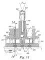
説明のこの時点に至るまで、カートリッジ受け部302と酸素添加装置54との間の種々のインタフェースの全てについて、1つの例外を除いて説明した。上述したように、酸素添加装置54は、生理的溶液をチャンバ58内に引き込んでこれを圧力下で霧化チャンバ62に送るように構成されたピストン組立体160を有している。図8に示すように、プランジャ164は、一端にキー176を有している。この説明中に言及するように、キー176は、ピストン組立体160をその伸長位置と引込み位置との間で動かす装置のキースロットに嵌まり込むよう形作られている。
多種多様な機構を用いてこの機能を達成することができるが、この実施形態で利用される駆動機構が、図40に示されていて、全体が符号700で示されている。一般的に言って、駆動機構700は、モータ704によって駆動されると共に制御されるボールねじ機構702を有している。この実施形態では、モータ704は、位置が光学エンコーダ706によってモニタされるステッピングモータである。モータ704をボールねじ機構702に直接結合できるが、この実施形態では、モータ704からの動力をボールねじ機構702に伝達するために伝動装置708が設けられている。具体的に説明すると、モータ704の出力シャフト710は、歯車712に結合されている。歯車712は、ねじ716を回転させるよう作動的に結合された歯車714と噛み合っている。この実施形態では、歯車712,714の駆動比は、1:1である。しかしながら、任意適当な駆動比を用いることができる。
モータ704がねじ716を回転させると、「駆動」組立体718は、ねじ716の回転方向に応じて、ほぼ矢印720の方向にねじ716の上で上昇し又は下降する。駆動組立体718の頂部のところでねじ716の周りにはラム722が摺動自在に設けられている。ラム722は、ピストン組立体160のキー176を受け入れるよう形作られたキー溝724を有している。それ故、ラム722がねじ716の回転に応答して駆動組立体718と共に上下すると、ラムが、ピストン組立体160をチャンバ58内で前後に動かす。
駆動組立体718は有利には、ラム722がピストン組立体160をチャンバ58に押し込むよう延びると荷重が加わるロードセル726を有する。ロードセル726に及ぼされる力は、ピストン組立体160が流体を通路190から追い出すときのチャンバ58内の流体圧力に関連している。したがって、ロードセル726から得た読みを用いると、ラム722の速度及び位置を制御して流体が所望の圧力で霧化チャンバ62に送られるようにすることができる。
[Piston drive mechanism]
Up to this point in the description, all of the various interfaces between the
A wide variety of mechanisms can be used to accomplish this function, but the drive mechanism utilized in this embodiment is shown in FIG. Generally speaking, the
As the
The
ステッピングモータ組立体700の構成部品を図41A及び図41Bの分解図に明確に示す。上述した構成部品に加え、歯車712,714は、それぞれの軸受730,732で支持されていることが理解できる。モータ704は、ブラケット734の一方の側部に取り付けられ、駆動組立体718を包囲するシュラウド736が、ブラケット734の他方の側部に取り付けられている。さらに、ねじ716がテーパしたスラスト軸受740で支持される継手738内に設けられていることが理解できる。スラスト軸受740は、ラム722を上方に押してピストン組立体160をチャンバ58に押し込む力に対応するのに有用である。
駆動組立体718は、ロードセルマウント744に螺着されたナット742を有している。さらに図42及び図43の断面図を参照すると、ロードセルマウント744は、閉鎖端部を備えたスロット746を有している。ロードセルマウント744をシュラウド736内に配置すると、スロット746は、止めピン748と整列する。止めピン748は、駆動組立体718がねじ716の回転に応じて下方に動くときに、駆動組立体718が底に付くのを阻止するためにスロット746内に設けられている。その代わり、駆動組立体718は、スロット746の端部が止めピン748に当たると停止する。
また、駆動組立体718がねじ716の回転に応じて回転するのではなく、軸方向に動くべきであることを理解すべきである。かかる運動を達成するため、案内737がシュラウド736の内壁上に設けられている。案内737は、駆動組立体がねじ716に沿って上下するときに、駆動組立体718の回転を阻止するようにロードセルマウント744に設けられたスロット747と連係する。駆動組立体718の回転が阻止されるので、駆動組立体は、ねじ716に対して軸方向に動く。
ラム722の下端部は、フランジ750を有している。フランジ750は、ロードセルカバー752の頂部に当たり、止めリング754が、ラム722の底部に結合されてロードセル726及びロードセルカバー752をラム722に固定するようになっている。ロードセルカバー752は、ねじ756によりロードセルマウント744に更に結合されている。最後に、ラム722の上端部は、軸受758を通って設けられ、カバープレート760が、シュラウド736の頂部に螺着されている。
The components of the stepping
The
It should also be understood that the
The lower end of the
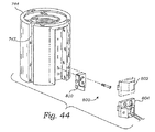
ステッピングモータ組立体700は、図44〜図48に示すようにセンサ組立体800を更に有している。センサ組立体800は、2つの信号をシステムコントローラ55に送る。第1の信号は、駆動組立体718、かくして、ピストン組立体160がその最大行程、即ち、その最大伸長状態に達すると生じる。第2の信号は、駆動組立体718、かくして、ピストン組立体160がそのホームポジション、即ち、最大引込み状態に達すると生じる。最大行程信号は、ピストン組立体160のキャップ166がチャンバ58の端部に達しないようにするのに役立つ。ホームポジション信号は、光学エンコーダ706をリセットしてこれが駆動組立体718の既知の位置からモータ704のモニタを開始することができるようにするのに役立つ。
図44及び図46に示すように、センサ組立体800は、最大行程センサ802及びホームポジションセンサ804を有している。この実施形態では、センサ802,804は、光学センサである。かくして、図48に最もよく示されているように、センサ802,804は各々、光学トランスミッタ806及び光学レシーバ808を有している。光学トランスミッタ806と光学レシーバ808との間の経路に障害物が無いままである限り、光学レシーバ808は、光学トランスミッタ806から伝送された光信号を受取る。しかしながら、光学トランスミッタ806と光学レシーバ808との間に障害物があると、光学レシーバ808は、光学トランスミッタ806から送られた光信号を受取らない。かくして、この状況では、光学センサ802又は804の出力が変化して、障害物が存在していることを指示することになる。
図47に最もよく示すように、センサ組立体800のこの実施形態では、タブ又はフラグ810がロードセルマウント744に結合されている。この実施形態では、ねじ812,814が、フラグ810をロードセルマウント744に結合するのに用いられる。ただし、任意適当な取付け構造を利用してもよい。図46及び図47は、駆動組立体718をホームポジションで示している。したがって、フラグ810は、ホームポジションセンサ804の光学トランスミッタ806と光学レシーバ808との間に配置されている。
The stepping
As shown in FIGS. 44 and 46, the
As best shown in FIG. 47, in this embodiment of
〔概略的なシステムの作用〕
システム10の種々の機械的構成部品を説明したので、システム10が種々の電気構成部品の制御下でどのように作用するかについて以下に説明する。図49を参照すると、状態図900が、システム10のこの実施形態の基本的な作用を示している。
システム10の電源をオンにし又はリセットすると、システム10は、初期化モード902に入る。初期化モードでは、システムコントローラ55は、種々のシステムパラメータを設定し、種々の診断チェックを行う。例えば、システム10の電源をオフにした最後の時点でシステム10の電源を不適切に切った場合、エラーコードが出される場合がある。さらに、システム10にウォッチドッグタイマの故障が生じると(この故障は一般に、そのプロセッサが故障し又は正しく機能しないことを意味する)、システムは、ウォッチドッグ故障モード904に入る。
[Outline of system operation]
Having described the various mechanical components of the
When the
初期化モード902では、システムコントローラ55は又、カートリッジ存在センサ520によって送られたカートリッジ存在信号を読み取る。図50に示すように、カートリッジ存在信号は、CPU908による処理の前にIOレジスタサブシステム906によって処理される。酸素添加装置54がカートリッジ包囲体26内に存在していると、システムは、初期化モード902から取外しモード即ちアンロードモード910に切り換わる。アンロードモード910では、酸素添加装置54は減圧され、ドアは解錠されて酸素添加装置54の取出しが可能になる。使用済み酸素添加装置54の取出しは、同一の酸素添加装置54が多数の患者に使用されないようにするのに望ましい。酸素添加装置54を減圧するため、システムコントローラ55は、O2通気信号912を、霧化チャンバ62と関連したソレノイド426に送り、血液混合チャンバ通気信号914を混合チャンバ64と関連したソレノイド428に送る。上述したように、ソレノイド426,428は、それぞれ対応関係にあるピン422,424を引っ込めて通気弁258,260が開くことができるようにすることにより応動する。酸素添加装置54をいったん減圧すると、システムコントローラ55は、ドアロック信号916を無効にし、それにより、ソレノイド348が引っ込んで止めピン342をドアラッチ310から引っ込める。
ユーザが30秒以内に酸素添加装置54を取外さない場合、一次的な中断、即ち、タイムアウトが起こり、システム10は、待機モード3と表示されている待機状態920に切り換わる。待機モード3の状態920では、アンロードコマンドが引き続き送り出され、システム10はユーザが取外し操作を完了するまでアンロードモード910と待機モード3との間で切り換わるようになる。次に、酸素添加装置54が存在していない場合、システムは、待機モード3の状態920から切り換わって初期化モード902に戻る。
In the
If the user does not remove the
初期化がいったん完了すると、システム10は、待機モード1の状態922に切り換わる。待機モード1の状態922では、システムコントローラ55は、RS−232シリアル通信ポート924をモニタしてホスト/ユーザインタフェース66からの塔載コマンド、即ち、ロードコマンドを待つ。ロードコマンドを受取ると、システム10は、ロードモード926に切り換わる。ロードモード926により、ユーザは、新しい酸素添加装置54を塔載し、始動に備えてシステムを準備する。ロードモード926では、全ての弁作動ピン382,384,386,422,424及びドアロックピン342を引っ込める。弁作動ピンを引っ込めることが望ましいのは、伸長した状態の作動ピンは、酸素添加装置54がカートリッジ包囲体26内に正しく設置されるのを阻止する場合があるからである。弁作動ピン382,384,386,422,424及びドアロックピン342を引っ込めるため、システムコントローラ55は、充填信号930、フラッシュ信号932、AO流れ信号934、O2通気信号912、血液混合チャンバ通気信号914及びロック信号916をそれぞれソレノイド388,390,392,426,428,348に送る。
Once initialization is complete, the
上述のアンロードモード910と同様、ロードモード926は、タイマ、例えば、30秒のタイムアウトを更に有し、もしユーザが割り当てられた時間内に酸素添加装置54を塔載しなければ、システム10は、タイマによりロードモード926から待機モード1の状態922に戻る。しかしながら、ユーザがカートリッジ存在信号520によって指示されるように、酸素添加装置54をカートリッジ包囲体26内に首尾良くいったん塔載すると、弁作動ピン382,384,386,422,424及びドアロックピン342を全て伸長させて、それぞれの対応関係にある弁202,204,206,258,260がこれらの閉鎖位置に保持され、ラッチ310がドア304を閉じたときにロックするようにする。
ドア304をいったん閉じてロックすると、ロード動作は完了し、システム10は、ロードモード926から待機モード2の状態940に切り換わる。待機モード2の状態940では、システムコントローラ55は、RS−232シリアル通信ポート924をモニタして、準備コマンド即ちプライムコマンド又はアンロードコマンドの何れかを待つ。アンロードコマンドを受取ると、システム10は、上述したように動作するアンロードモード910に移行する。しかしながら、プライムコマンドを受取ると、システム10は、プライムモード942に移行する。
Similar to the unload
Once
ユーザは、プライムスイッチ108を押すことによりプライムモード942を開始させる。プライムモード942では、システム10は、流体供給チャンバ58を生理的溶液で満たし、ピストン組立体160を駆動してこの溶液を加圧し、流体が適当なレベルに達するまで溶液を霧化チャンバ62内へ移送する。プライムモード942では、システムコントローラ55のステッピングモータ駆動サブシステム950が、ステッピングモータ704の位置をエンコーダ706から読み取り、そしてステッピングモータ704を駆動して、ラム722がピストン組立体160を流体供給チャンバ58内のその完全伸長位置に押す。ピストン組立体160を引っ込めると、生理的溶液は、通路144を通って流体供給チャンバ58内に吸い込まれる。ピストン組立体160は次に再び伸長して流体供給チャンバ58内の生理的溶液を加圧し、これを流体供給チャンバ58から霧化チャンバ62内へ移送する。このモードでは、充填弁202が開かれ、流体が霧化器216ではなく、管232を通って霧化チャンバ62に流入する。
システムコントローラ55がAOレベルセンサ480から霧化チャンバ62が適度に充填されているということを示す信号を受取ると、ステッピングモータ駆動サブシステム950は、ピストン組立体160をホームポジションに引っ込め、次にピストン組立体160を伸長させて追加の量の溶液、例えば、3ccを霧化チャンバ62内へ移送する。霧化チャンバ62に生理的溶液を入れた後、システムコントローラ55は、O2フロー信号952をO2フローソレノイド954に送り、弁956を開いて供給源60からの酸素が霧化チャンバ62を加圧できるようにする。
いったん流体が適正なレベルに達すると、プライムモード942が完了する。しかしながら、プライム動作の完了の前に、プライム動作におけるエラーになること又はユーザが停止スイッチ112を押すことの何れかの結果として送られた停止コマンドによってプライム動作が中断されると、システム10はプライムモード942から待機モード2の状態940に移行する。
The user starts the
When the
Once the fluid reaches the proper level,
いったんプライムモード942が完了すると、システム10はAOオフモード960に移行する。AOオフモード960にある間、水性酸素は作られず、即ち、送られない。その代わり、システムコントローラ55は、フラッシュ信号932をソレノイド390に送ってフラッシュ弁204を開く。上述したように、フラッシュ弁204が開いているとき、生理的溶液は、流体供給チャンバ58から弁組立体200を通り、毛管246を通って混合チャンバ64に流入する。この送りモードは、混合チャンバ64を通る血液の流れが所定の流量、例えば、毎分50mlよりも多い限り続く。血液流量が所定流量を下回ると、システム10は、タイムアウトモード962に移行する。タイムアウトモード962では、システム10は、流れ、充填又はフラッシュを行わず、ピストン組立体160は、ホームポジションに戻る。システム10は、アンロードコマンドをホスト/ユーザインタフェース66から受取った場合、又は、システム10が所定の時間、例えば、150秒間タイムアウトモード962にあった場合、タイムアウトモード962からアンロードモード910に移行することになろう。しかしながら、血液の流量がいったん所定流量を上回ると、システム10は、タイムアウトモード962からAOオフモード960に戻る。
Once
AOオンコマンドを受取ると、システム10は、AOオフモード960からAOオンモード964に移行する。AOオンコマンドは、ユーザがプライムボタン108とスタートボタン110とを同時に押すと生じる。AOオンモード964では、プライム信号が血液ポンプシステム24からライン966を経てインターロックシステム44に送られる。システムコントローラ55がプライムコマンドを受取ったときに、AOオフモード960にあると、インターロックシステム44のロジックブロック134は、イネーブル信号をライン126を経て送って血液ポンプ24を稼働させる。ロジックブロック134は又、引出し側クランプ信号をライン970を経て引出し側クランプ78に送り、戻り側クランプ80が閉鎖状態のまま引出し側クランプ78を開く。ロジックブロック130は又、プライム信号をライン968を経てシステムコントローラ55のCPU908に送る。プライム信号の受信に応答して、システムコントローラ55は、低レベルセンサ484をモニタして、混合チャンバを低レベルセンサ484で指示されるレベルまで充填するため、十分な量の血液が混合チャンバ64に流入したかどうかを判定する。低レベル信号は又、ライン974を経てインターロックシステム44のロジックブロック134に送られる。インターロックシステム44により、チャンバ64を低レベルセンサ484によって指示されたレベルまで充填したことが確認されると、インターロックシステムは、戻り側クランプ信号をライン972を経て戻り側クランプ80に送ってこれを開く。それと同時に、システムコントローラ55は、通気弁260を閉鎖するためにサイクロックス(cyclox)通気信号914をソレノイド428に送る。
Upon receipt of the AO on command, the
システム10は、もし血液の流量が所定の流量、例えば、毎分50mlを下回らなければ、このようにAOオンモード964で動作し続ける。この場合、システム10は、AOオンモード964からアンロードモード910に移行し、これは、上述したように動作することになる。
インターロックシステム44のロジックブロック134も又、AOイネーブル信号をライン976を経てシステムコントローラ55のCPU908に送る。AOイネーブル信号により、システムコントローラ55は、AOフロー信号934をソレノイド392に送ってフロー弁206を開く。上述したように、フロー弁206が開いた状態で、水性酸素は、霧化チャンバ62から毛管246を通って混合チャンバ64に流入して血液と混合される。
The
〔気泡検出器〕
上述したように、システム10は、有利には、戻り管50内の酸素富化血液を気泡について監視即ちモニタするために気泡センサ76と連結された気泡検出器74を有している。気泡検出器74の例示の実施形態を図51に示す。気泡検出器74は、その機能の多くをソフトウェアの制御下で実行するように動作するディジタル信号プロセッサ(DSP)1000を有している。気泡検出器74は、ライン1002,1004のそれぞれにより、戻り圧力信号及び流量信号をインターロックシステム44から受取る。アナログ−ディジタル変換器(ADC)1006は、これらのアナログ信号を受取ってディジタル信号に変換する。これらのディジタル信号は、ADC1006からマイクロコントローラ1008に送られる。マイクロコントローラ1008は、ユーザ入力をホスト/ユーザインタフェース66からRS−232シリアル通信ポート1010を通して受取り、開始信号をインターロックシステム44からライン1012を通して受取る。
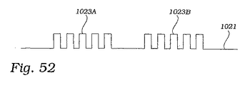
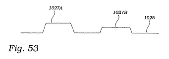
DSP1000及びマイクロコントローラ1008は、インタフェース及び制御ロジック1014を介して互いに連結されている。インタフェース及び制御ロジック1014は、DSP1000及びマイクロコントローラ1008からの入力に基づき、変換器駆動信号をライン1016を介して変換器ドライバ1018に送る。これに応答して、変換器ドライバ1018は、信号をライン1020を経て変換器76に送る。図52に示すように、変換器76が送った伝送信号は、高周波パルスのバースト(burst)1023A,1023Bを含む。例えば、各パルスバーストは、3.6MHzの20個のパルスを含み、バーストとバーストとの間は50マイクロ秒である。変換器76からの戻り信号は、ライン1022により受信される。変換器76からライン1022を経て受取った信号は、伝送信号1021に似ているが、時間が後にずれ且つ振幅が小さくなっている。典型的には、気泡が変換器76を通過するのに1つのバーストの期間よりも長い時間がかかる。したがって、バースト期間中、パルスを送る度に各気泡をサンプリングし、例えば、この例では、気泡が変換器76を通過するとき、各気泡を20回サンプリングする。
(Bubble detector)
As described above, the
The
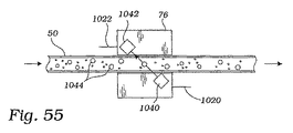
ライン1020上の伝送信号に対するライン1022上の受信信号の強さは、戻り管50内の気泡の存在に関する情報を提供する。図54に示すように、気泡センサ76は、超音波送信器1040及び超音波受信器1042を含む。気泡センサ76は、有利には、戻り管50の外部に取付けられている。かくして、超音波送信器1040からの超音波信号は、戻り管50及び戻り管50内の流体を介して超音波受信器1042に送られる。戻り管50内の流体が気泡を含んでいない場合、超音波信号は、ト超音波送信器1040から比較的効率的に超音波受信器1042に伝搬する。かくして、超音波受信器1042によりライン1022を経て送られる戻り信号の信号強さは、比較的強い。しかしながら、戻り管50内の流体が気泡1044を含む場合、図55に示すように、超音波受信器1042によって受取られる超音波信号は弱くなり、減衰されている。気泡を含む流体を横切る超音波信号のより弱く減衰した伝搬は、気泡1044が超音波信号を散乱させる傾向があることに起因し、その結果、最終的には、より少ない伝搬信号が超音波受信器1042によって受取られることになる。
一例として、図53に示すように、第1のピーク1027Aは、気泡を含まない流体を通って伝送された信号を示し、第2のピーク1027Bは、気泡を含む流体を通って伝送された信号を示している。ピーク1027Bの相対的な弱さは、ピーク1027Bの減少によって示されている。ピーク1027Bの減少(減衰)の程度は、信号が伝送された時点における気泡センサ76を通る気泡の直径と関連している。具体的に説明すると、信号の減少(減衰)量1046は、気泡の断面積、かくして、気泡の直径の2乗に関連していて、信号の平方根は気泡のサイズ、かくして、その直径に正比例するようになっている。
The strength of the received signal on
As an example, as shown in FIG. 53, a
戻り信号の処理を容易にするため、戻り信号は、信号調整器1024に送られる。信号調整器1024は、戻り信号を増幅して濾波する。次に、信号調整器1024は、信号の超音波エネルギの量を検出し、これをアナログ−ディジタル変換器(ADC)1026に送る。ADC1026に送られた信号1025を図53に示す。信号1025の検討から理解できるように、高周波パルス列1023A,1023Bはそれぞれ、単一のピーク1027A,1027Bに類似している。ADC1026は、振幅信号1025のピーク1027A,1027Bだけをサンプリングする。この例では、各ピーク1027A,1027Bは、幅が約6.6マイクロ秒であり、ADC1026は、128個のピークをサンプリングして128個のデータポイントを確立する。
ADC1026のディジタル出力は、バッファ、例えば、先入れ先出し(FIFO)バッファ1030に送られる。バッファ1030は、128個のピークのディジタル表現を記憶し、これらを1つずつDSP1000に送る。インタフェース及び制御ロジック1014は、バッファ1030からDSP1000への信号の送りを制御する。
DSP1000は、ディジタルピークの各々についてデータポイントを読み取り、ディジタルピークを合計する。ディジタルピークの合計は、受取った超音波エネルギの量と相関している。この実施形態では、DSP1000は、直前の16,000個又はそれ以上のピークの合計の移動平均を保有する。現時点の合計を移動平均から差し引いて、任意のDCオフセットを効果的に取除くハイパスフィルタを構成する。DSP1000はまた、FIRアレイを通して結果的に得られた信号を畳み込む(convolve)ことによって、ローパスフィルタの機能を発揮する。この例では、FIRアレイは、64ポイントアレイである。濾波は、気泡が信号中のノイズから区別されるように行われる。結果的に得られたサイズの異なる気泡の信号を図61に示す。
The return signal is sent to the
The digital output of the
The
検出した各気泡の直径をDSP1000によっていったん決定したら、DSP1000は、気泡の容積を計算する。しかしながら、理解すべきこととして、患者38に送られる気泡の容積は、戻り管50内の流体の圧力により影響を受ける。戻り管50内の流体の圧力は、患者の血管内の血液、例えば、約1気圧であるのと比較して、高く、例えば、約2〜3気圧であるのが通例なので、いったん気泡が患者38に達するときの気泡の容積を求めるための変換を行うのが有利である。戻り管50内の圧力はライン1002を経て気泡検出器74に送られ、また、患者の血液の圧力を理想気体の法則を用いて1気圧であると仮定できるので、患者のところにおける気泡の容積は、Vp=(Ps・Vs)/Paに等しく、この式において、Vpは患者38のところでの気泡の容積、Psは、気泡センサ76のところでの圧力、Vsは、気泡センサ76のところでの気泡の容積、Paは大気圧である。
Once the diameter of each detected bubble is determined by the
DSP1000は、或る特定のサイズの気泡を適当な「ビン」即ちカテゴリーに入れるのが有利である。換言すると、DSP1000は、気泡サイズの異なるカテゴリーを維持するのがよい。例えば、カテゴリーは、75ミクロン直径刻みの16のビンを含む。各カテゴリー内の気泡の数は、ディスプレイ32に送られて、ユーザが外科処置中に生じている気泡の数及びサイズをモニタすることができるようにする。気泡の数及びサイズは又、システム10の作動をモニタするために気泡検出器74又はシステム10内のどこか他の場所でモニタするのがよい。
気泡検出器74は、経時的に検出された全ての気泡の総容積を累積し、即ち、各気泡の容積を現在の合計に加えるのが良い。規定の時間内において、現在の合計、即ち、累積容積が規定の容積又は限度を超えるとき、システム10の作動を変更するのがよい。例えば、気泡の総容積が90分で10マイクロリットルを超えれば、気泡検出器74は、「停止要求」信号をライン1050上に送るのが良い。この実施形態では、停止要求信号は、インターロックシステム44によって受取られ、その結果、インターロックシステム44は、上述したようにシステム10の運転を停止させることが可能になる。大抵の患者は、代表的には、経時的に少量のガスを溶解させるので、進んだやり方として、現在の合計を減らして、システム10の作動停止をトリガする所定の限度にすぐに到達しないようにしても良い。加えて、所定の限度に達する前に、気泡検出器74は、作動停止が差し迫っているという早期の警告を出して、システムコントローラ55が戻り管50内の血液のpO2レベルを下げて気泡生成を抑制し、かくして、作動停止を回避することができるようにしても良い。
The
The
〔気泡検出器の評価又は校正〕
個々の超音波プローブは、種々の程度の分解能を有している。したがって、気泡を検出できる気泡検出器の能力の限界は、幾つかの気泡のサイズ及び/又は速度が超音波プローブの分解能を超えた場合に生じることがある。状況に応じて、ミクロ気泡(直径が約50μm〜約1000μmの気泡)及び/又はマクロ気泡(直径が1000μm以上の気泡)が検出を逃れることがある。気泡が検出を逃れると、気泡検出器の精度が損なわれる場合がある。
かくして、気泡検出器の気泡検出能力を評価するシステム及び方法を利用することが望ましい。以下に説明する評価システム及び方法は、複数の流量及び物質粘度における気泡検出器のミクロ気泡及びマクロ気泡の分解能を求めることができる。概略的には、決定可能なサイズの気泡を流れ物質中に導入する。流れ物質中に導入された気泡のサイズ及び量は、評価対象の気泡検出器によって検出される。しかる後、流れ物質中に導入された気泡のサイズ及び量を別個独立に決定する。
[Evaluation or calibration of bubble detector]
Individual ultrasonic probes have various degrees of resolution. Thus, the limit of the bubble detector's ability to detect bubbles may occur when the size and / or velocity of some bubbles exceeds the resolution of the ultrasound probe. Depending on the situation, micro bubbles (bubbles with a diameter of about 50 μm to about 1000 μm) and / or macro bubbles (bubbles with a diameter of 1000 μm or more) may escape detection. If the bubbles escape detection, the accuracy of the bubble detector may be impaired.
Thus, it is desirable to utilize a system and method for evaluating the bubble detection capability of a bubble detector. The evaluation system and method described below can determine the resolution of bubble detector microbubbles and macrobubbles at multiple flow rates and material viscosities. In general, a determinable size bubble is introduced into the flow material. The size and amount of bubbles introduced into the flow material are detected by a bubble detector to be evaluated. Thereafter, the size and amount of bubbles introduced into the flow material are independently determined.
気泡検出器、例えば、気泡検出器74の校正及び評価システム1105の例示の実施形態を図56に示す。このシステム及び方法により、従事者が気泡サイズ、気泡生成速度及び流れ物質の流量を制御することを可能にする。システム1105は、流れ物質1112を貯蔵する格納容器1110を用いている。容器1110は、入口1116及び出口1118を有し、流れ物質1112が全体として矢印1119の方向に流れるようになっている。ポンプ1120、例えば蠕動ポンプが、所望の流量をもたらし且つこれを維持するのに利用される。有利には、ポンプ1120は、流れ物質1112を複数の流量で送ることができる。種々の粘性の流れ物質1112を利用するのがよく、かかる流れ物質としては、ニュートン流体又は非ニュートン流体が挙げられる。代表的には、評価に用いられる流れ物質1112の粘性は、動作環境で利用される物質、例えば、この例ではガス富化生理的流体と混合した血液の粘性と同程度である。
システム1105は、代表的には、所定の内径及び所定の長さの第1の導管1130を用いており、この第1の導管は、近位端部1132及び遠位端部1134を有し、これら端部を通って、流れ物質1112を種々の流量で通過させることができる。近位端部1132は、容器1110から流れ物質1112を受け入れるよう出口1118に結合されている。遠位端部1134は、連結装置1140に結合されている。連結装置1140、例えば、Tコネクタは、代表的には、第1の導管1130と流体連通状態をなした状態でその長手方向軸線に沿って設けられていて、流れ物質1112の連続した妨げの無い流れを可能にしている。
気泡生成物質1150の導入により流れ物質1112中に気泡生成を生じさせる気泡生成器具1143を用いるのがよい。気泡生成物質1150は、典型的には、空気等のガスを含む。流れ物質1112は、気泡生成及び保持を促進する界面活性剤、例えば、ドデシル硫酸ナトリウム(SDS)を含むのがよい。
An exemplary embodiment of a calibration and
The
It is preferable to use a
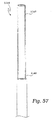
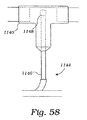
図57及び図58に最もよく示すように、気泡生成装置1143は、この例では、気泡生成毛管1144を有し、この気泡生成毛管1144は、代表的には、所定内径及び所定長さのものである。毛管1144は、近位端部1146及び遠位端部1148を有している。近位端部1146は、気泡生成ルーメン1153によりポンプ装置1155、例えば、注入器(シリンジ)に取り付けられている。気泡ポンプ装置1155は代表的には、気泡生成物質1150を種々の注入量で流れ物質1112中に注入することができる。毛管1144の遠位端部1148は、流れ物質1112に入り込んでいる連結装置1140の内部に配置されるよう摺動自在に構成されており、その結果、流れ物質1112内に気泡が生じる。この例では、毛管1144は、流れ物質1112の流れ方向の長手方向軸線に垂直に又はほぼ垂直に位置決めされていて、流れの剪断力の合力が一定サイズの気泡を一定速度で生じさせるようになっている。
気泡のサイズは、毛管1144の内径により、又は毛管1144の遠位部分1148を物質の流れ内の種々の位置に配置することにより調整できる。毛管1144の内径を増大させると、気泡サイズが増大する。これと同様に、毛管1144の遠位部分1148を流れ物質1112の長手方向軸線から遠ざけて配置すると、気泡サイズが増大する。気泡生成速度は、流れ物質1112中へ導入される気泡生成物質1150の流量を増減させることにより変化させることができる。例えば、気泡生成物質1150の流量の増大により、流れ物質1112中の気泡生成速度が増大する。
As best shown in FIGS. 57 and 58, the
The bubble size can be adjusted by the inner diameter of the capillary 1144 or by placing the
システム1105は、代表的には、所定内径及び所定長さの第2の導管1170を更に用いている。第2の導管1170の近位端部1172は、連結装置1140に結合され、第2の導管1170の遠位端部1174は、格納容器1110の入口1116に結合されている。実質的に一定の流量を導管1130,1170内に維持するため、第2の導管1170は、通常、第1の導管1130と同軸に整列し、第2の導管1170の直径は、通常、第1の導管1130の直径に等しい。評価すべき気泡検出器74のプローブ76は、第2の導管1170を通って流れる流れ物質1112内の気泡を検出できるよう第2の導管1170の近位側に位置決めされている。
連結装置1140は、気泡生成プロセスの目視検査を可能にするよう光学的に透明であるのがよい。当然のことながら、CCDカメラ等の記録装置1160を毛管1144の遠位端部1148上に合焦させて流れ物質1112中の気泡のサイズ及び量を観察して記録するのがよい。かくして、気泡検出器、例えば、気泡検出器74を校正するには、プローブ76で検出された気泡のサイズ及び量を記録装置1160によって測定された気泡のサイズ及び量と比較するのがよい。第2の検査装置(図示せず)を気泡検出器プローブ76と格納容器1110の入口1116との間で第2の導管1170に沿って設け、流れ物質1112への従事者の接近を可能にするのがよい。
The
The
作用を説明すると、ポンプ1120を作動させることにより流れを開始させる。流れ物質1112の流量が、気泡をシステム1105に導入する前に安定化するようにする。システム1105がいったん安定化したら、気泡生成装置1143を作動させることにより気泡を流れ物質1112に導入する。システム1105が、気泡検出器74を校正する前にもう一度安定化するようにする。
気泡検出器74のミクロ気泡分解能は、連続試験において直径を連続的に小さくした気泡を導入することにより測定できる。気泡検出器74のマクロ気泡分解能は、同様な方法で、連続試験において直径を連続的に大きくした気泡を導入することにより測定できる。気泡生成速度及び流量がいったん安定化すると、記録装置1160を作動させて気泡生成速度及び生じた気泡のサイズを記録する。評価すべき気泡検出器74を所定の時間作動させる。
プローブ76は、一般に既知のサイズ及び量の気泡を検査し、プローブ76はこれに対応した信号を気泡検出器74に送る。気泡検出器74によって記録された気泡のサイズ及び量を記録装置1160によって記録されている気泡のサイズ及び量と比較する。代表的には、かかる比較は、複数の信号強度及び気泡サイズで行われる。しかる後、数学専門家が、この関係をグラフ表示して複数の気泡サイズのところでの投影信号強度を外挿する。信号と気泡サイズの関係をグラフにプロットすると、数学専門家は、信号強度と気泡サイズの関係の当てはめに基づいて1以上の校正定数を計算することができる。校正定数を気泡検出器74にプログラムすると気泡検出器74を校正することができる。
In operation, the flow is started by operating the
The microbubble resolution of the
校正及び評価システム1105の変形実施形態は、図59に示すように、パルス減衰器1180が設けられていることを除き、上述のシステムと同一である。パルス減衰器1180は、ポンプ1120により生じた圧力振動を減少させ又は無くす。加えて、かかる圧力振動により生じ又は流れ回路内で再循環する場合がある比較的大きな気泡は、パルス減衰器1180内に捕捉状態になって、これらが気泡生成装置1143によって制御された気泡の生成を妨害しないようにする。
さらに図60を参照すると、パルス減衰器1180は、入口1182及び出口1184を備えた容器本体1181を有していることが示されている。入口1182は、ポンプ1120と連結装置1140との間で第1の導管1130内に結合されている。ポンプ1120は、流れ物質1112を入口1182を通って容器本体1181に押し込む。ポンプ1120によって及ぼされる圧力は、容器本体1181内で維持され、かくして、流れ物質1112を出口1184から押し出す。かくして、ポンプ1120により生じた気泡は、連結装置1140に達する前に捕捉される。
本発明は、種々の設計変更及び変形形態で実施できるが、特定の実施形態が図面に例示として示され、本明細書において詳細に説明した。しかしながら、本発明は開示した特定の形態に限定されるものではないことは理解されるべきである。それどころか、本発明は、特許請求の範囲に記載された本発明の精神及び範囲に属する全ての設計変更例、均等例及び変形例を含むものである。
A modified embodiment of the calibration and
Still referring to FIG. 60, the
While the invention may be practiced with various design modifications and variations, specific embodiments have been shown by way of example in the drawings and have been described in detail herein. However, it should be understood that the invention is not limited to the specific forms disclosed. On the contrary, the present invention includes all modifications, equivalents, and variations belonging to the spirit and scope of the present invention as recited in the claims.
Claims (33)
患者から体内流体を送るためのポンプシステム(24)と、
体内流体を受取るように前記ポンプシステム(24)に作動的に結合され、ガス富化体内流体を形成するために体内流体とガスを組み合わせるガス富化装置と、
ガス富化体内流体中の気泡を検出する気泡検出器(74)と、
前記ポンプシステム(24)及び前記ガス富化装置を自動的に制御するコントローラ(28)と、を有し、
前記ガス富化装置は、包囲体(26)内に配置される使い捨てカートリッジを有し、この使い捨てカートリッジは、
ハウジング(16)と、
ガス富化生理的流体を形成するために前記ハウジング(16)内に設けられた富化装置と、
前記ハウジング(16)内に設けられ、ガス富化体内流体を形成するためにガス富化生理的流体と体内流体を混合させる混合装置と、
生理的流体を前記富化装置に供給するために前記ハウジング(16)内に設けられた流体供給装置と、
前記ハウジング(16)内に設けられた弁組立体と、を有し、この弁組立体は、前記流体供給装置と前記富化装置との間の生理的流体の流量を制御すると共に前記富化装置と前記混合装置との間のガス富化生理的流体の流量を制御する弁を有することを特徴とするシステム。A system for enriching bodily fluids with gas,
A pump system (24) for delivering bodily fluids from the patient;
A gas enrichment device operatively coupled to the pump system (24) to receive a bodily fluid and combining the bodily fluid and gas to form a gas-enriched bodily fluid;
A bubble detector (74) for detecting bubbles in the gas-enriched body fluid;
A controller (28) for automatically controlling the pump system (24) and the gas enrichment device;
The gas enrichment device has a disposable cartridge disposed within the enclosure (26), the disposable cartridge comprising:
A housing (16);
An enrichment device provided in the housing (16) to form a gas-enriched physiological fluid;
A mixing device provided in the housing (16) for mixing the gas-enriched physiological fluid and the body fluid to form a gas-enriched body fluid;
A fluid supply device provided in the housing (16) for supplying physiological fluid to the enrichment device;
A valve assembly provided in the housing (16), wherein the valve assembly controls the flow rate of physiological fluid between the fluid supply device and the enrichment device and the enrichment. A system comprising a valve for controlling a flow of gas-enriched physiological fluid between a device and the mixing device.
送信変換器(1040)及び受信変換器(1042)を有し、流体流れ中の気泡を検出するように位置決め可能な超音波変換器の対(1040,1042)と、
前記送信変換器(1040)がパルス化超音波信号を流体流れを横切って前記受信変換器(1042)に送るように前記送信変換器(1040)に作動的に結合された変換器ドライバ(1018)と、
前記受信変換器(1042)からパルス化超音波信号を受取るように前記受信変換器(1042)に作動的に結合され、調整信号を生じさせるようにパルス化超音波信号を調整する信号調整器(1024)と、
調整信号を受取るよう前記信号調整器(1024)に作動的に結合され、調整信号に応答して、流体流れ中の気泡と相関関係にある情報を決定する信号プロセッサ(1000)と、を有する請求項1〜14の何れか1項に記載のシステム。The bubble detector (74)
A pair of ultrasonic transducers (1040, 1042) having a transmitting transducer (1040) and a receiving transducer (1042) and positionable to detect bubbles in the fluid flow;
A transducer driver (1018) operatively coupled to the transmit transducer (1040) such that the transmit transducer (1040) sends a pulsed ultrasound signal across the fluid flow to the receive transducer (1042) When,
A signal conditioner (operatingly coupled to the receiving transducer (1042) to receive a pulsed ultrasound signal from the receiving transducer (1042) and adjusting the pulsed ultrasound signal to produce an adjustment signal ( 1024)
A signal processor (1000) operatively coupled to the signal conditioner (1024) for receiving an adjustment signal and determining information correlated with bubbles in the fluid flow in response to the adjustment signal. Item 15. The system according to any one of Items 1 to 14.
前記ポンプシステム(24)をモニタするよう構成され、前記ポンプシステム(24)の作動と相関した少なくとも1つの第1の信号を送る第1のセンサ組立体と、
前記ガス富化装置をモニタするよう構成され、前記ガス富化装置の作動と相関した少なくとも1つの第2の信号を送る第2のセンサ組立体と、
少なくとも1つの第1の信号及び少なくとも1つの第2の信号を受取るように前記第1のセンサ組立体及び前記第2のセンサ組立体に作動的に結合された信号プロセッサ(1000)と、を有し、
前記信号プロセッサ(1000)は、少なくとも1つの第1の信号に応答して少なくとも1つのポンプシステム制御信号を送り、前記ポンプシステム(24)は、前記信号プロセッサ(1000)からの少なくとも1つのポンプシステム制御信号の受取りに応答して前記ポンプシステムの作動を調整し、前記信号プロセッサ(1000)は、少なくとも1つの第2の信号に応答して、少なくとも1つのガス富化制御信号を送り、前記コントローラは、前記信号プロセッサ(1000)からの少なくとも1つのガス富化信号の受取りに応答して、前記ガス富化装置の作動を調整するよう構成された作動組立体を更に有する請求項1〜26の何れか1項に記載のシステム。The controller is
A first sensor assembly configured to monitor the pump system (24) and to send at least one first signal correlated with operation of the pump system (24);
A second sensor assembly configured to monitor the gas enricher and to send at least one second signal correlated with operation of the gas enricher;
A signal processor (1000) operatively coupled to the first sensor assembly and the second sensor assembly to receive at least one first signal and at least one second signal. And
The signal processor (1000) sends at least one pump system control signal in response to at least one first signal, and the pump system (24) is at least one pump system from the signal processor (1000). Adjusting the operation of the pump system in response to receiving a control signal, wherein the signal processor (1000) sends at least one gas enrichment control signal in response to at least one second signal, the controller 27. An actuating assembly configured to adjust the operation of the gas enrichment device in response to receiving at least one gas enrichment signal from the signal processor (1000). The system according to any one of the above.
前記管(34)の戻り側に作動的に結合された第2のクランプ(80)と、を有し、
前記信号プロセッサ(1000)は、前記所望の流量範囲の外にある流量信号に応答して、前記第1のクランプ(78)及び前記第2のクランプ(80)を閉じる、請求項29〜31の何れか1項に記載のシステム。A first clamp (78) operatively coupled to the withdrawal side of the tube (34);
A second clamp (80) operatively coupled to the return side of the tube (34);
The signal processor (1000) closes the first clamp (78) and the second clamp (80) in response to a flow signal outside the desired flow range. The system according to any one of the above.
前記作動組立体は、前記包囲体(26)内に設けられ且つ前記弁組立体の弁を作動させる弁作動組立体を有する、請求項27〜32の何れか1項に記載のシステム。The second sensor assembly includes a transducer for measuring physiological fluid supplied by the fluid supply device, a first level sensor for measuring a fluid level in the enrichment device, and A second level sensor for measuring a low flow level in the mixing device and a third level sensor for measuring a high fluid level in the mixing device;
33. A system according to any one of claims 27 to 32, wherein the actuation assembly comprises a valve actuation assembly provided in the enclosure (26) and actuating a valve of the valve assembly.
Applications Claiming Priority (2)
| Application Number | Priority Date | Filing Date | Title |
|---|---|---|---|
| US09/813,068 US6582387B2 (en) | 2001-03-20 | 2001-03-20 | System for enriching a bodily fluid with a gas |
| PCT/US2002/008542 WO2002074364A2 (en) | 2001-03-20 | 2002-03-19 | System for enriching a bodily fluid with a gas |
Publications (3)
| Publication Number | Publication Date |
|---|---|
| JP2004524106A JP2004524106A (en) | 2004-08-12 |
| JP2004524106A5 JP2004524106A5 (en) | 2005-12-22 |
| JP4156376B2 true JP4156376B2 (en) | 2008-09-24 |
Family
ID=25211373
Family Applications (1)
| Application Number | Title | Priority Date | Filing Date |
|---|---|---|---|
| JP2002573071A Expired - Fee Related JP4156376B2 (en) | 2001-03-20 | 2002-03-19 | System for enriching bodily fluids with gas |
Country Status (7)
| Country | Link |
|---|---|
| US (2) | US6582387B2 (en) |
| EP (1) | EP1372759B1 (en) |
| JP (1) | JP4156376B2 (en) |
| AT (1) | ATE337808T1 (en) |
| DE (1) | DE60214352T2 (en) |
| ES (1) | ES2266479T3 (en) |
| WO (1) | WO2002074364A2 (en) |
Cited By (3)
| Publication number | Priority date | Publication date | Assignee | Title |
|---|---|---|---|---|
| US8192384B2 (en) | 2008-12-04 | 2012-06-05 | Therox, Inc. | System for enriching a bodily fluid with a gas having a dual-function power switch mechanism |
| US8246564B2 (en) | 2008-12-04 | 2012-08-21 | Therox, Inc. | System for enriching a bodily fluid with a gas having automated priming capabilities |
| US8636952B2 (en) | 2008-12-04 | 2014-01-28 | Therox, Inc. | System for enriching a bodily fluid with a gas having a removable gas-enrichment device with an information recording element |
Families Citing this family (482)
| Publication number | Priority date | Publication date | Assignee | Title |
|---|---|---|---|---|
| US6852090B2 (en) | 1997-02-14 | 2005-02-08 | Nxstage Medical, Inc. | Fluid processing systems and methods using extracorporeal fluid flow panels oriented within a cartridge |
| US7654728B2 (en) * | 1997-10-24 | 2010-02-02 | Revalesio Corporation | System and method for therapeutic application of dissolved oxygen |
| US6702949B2 (en) | 1997-10-24 | 2004-03-09 | Microdiffusion, Inc. | Diffuser/emulsifier for aquaculture applications |
| US7287398B2 (en) | 2001-09-25 | 2007-10-30 | Alsius Corporation | Heating/cooling system for indwelling heat exchange catheter |
| US6855123B2 (en) | 2002-08-02 | 2005-02-15 | Flow Cardia, Inc. | Therapeutic ultrasound system |
| US7780619B2 (en) * | 1999-11-29 | 2010-08-24 | Nxstage Medical, Inc. | Blood treatment apparatus |
| US6773670B2 (en) * | 2001-02-09 | 2004-08-10 | Cardiovention, Inc. C/O The Brenner Group, Inc. | Blood filter having a sensor for active gas removal and methods of use |
| US6582387B2 (en) * | 2001-03-20 | 2003-06-24 | Therox, Inc. | System for enriching a bodily fluid with a gas |
| US6613280B2 (en) * | 2001-03-20 | 2003-09-02 | Therox, Inc. | Disposable cartridge for producing gas-enriched fluids |
| US7771379B2 (en) * | 2001-05-24 | 2010-08-10 | Nxstage Medical, Inc. | Functional isolation of upgradeable components to reduce risk in medical treatment devices |
| EP1395241B9 (en) * | 2001-05-25 | 2005-06-15 | Medtronic, Inc. | Implantable medical device with controllable gaseous agent release system |
| ITMI20012829A1 (en) * | 2001-12-28 | 2003-06-28 | Gambro Dasco Spa | APPARATUS AND METHOD OF CONTROL IN A BLOOD EXTRACORPOREAL CIRCUIT |
| AU2003251567A1 (en) * | 2002-06-19 | 2004-01-06 | The Board Of Regents Of The University Of Texas System | Dialysis system for treatment of vulnerable patients and methods of use |
| US9955994B2 (en) | 2002-08-02 | 2018-05-01 | Flowcardia, Inc. | Ultrasound catheter having protective feature against breakage |
| US6942677B2 (en) | 2003-02-26 | 2005-09-13 | Flowcardia, Inc. | Ultrasound catheter apparatus |
| US7335180B2 (en) | 2003-11-24 | 2008-02-26 | Flowcardia, Inc. | Steerable ultrasound catheter |
| US20050267401A1 (en) * | 2004-05-25 | 2005-12-01 | Sherwood Services, Ag. | Safety interlock system for an enteral feeding pump |
| US20070084897A1 (en) | 2003-05-20 | 2007-04-19 | Shelton Frederick E Iv | Articulating surgical stapling instrument incorporating a two-piece e-beam firing mechanism |
| US9060770B2 (en) | 2003-05-20 | 2015-06-23 | Ethicon Endo-Surgery, Inc. | Robotically-driven surgical instrument with E-beam driver |
| EP2287549B1 (en) * | 2003-08-06 | 2016-11-30 | Zoll Circulation, Inc. | Heating/cooling system for indwelling heat exchange catheter |
| US7758510B2 (en) | 2003-09-19 | 2010-07-20 | Flowcardia, Inc. | Connector for securing ultrasound catheter to transducer |
| US7455812B2 (en) * | 2003-10-16 | 2008-11-25 | Rheoxtech, Llc | Method and apparatus for controlled reoxygenation |
| CN1305535C (en) * | 2003-12-29 | 2007-03-21 | 邢军 | Medical high oxygen liquid, human blood oxygenating method and its instrument |
| US7794423B2 (en) | 2004-05-25 | 2010-09-14 | Covidien Ag | Re-certification system for a flow control apparatus |
| US7462170B2 (en) | 2004-05-25 | 2008-12-09 | Covidien Ag | Administration feeding set and valve mechanism |
| US11890012B2 (en) | 2004-07-28 | 2024-02-06 | Cilag Gmbh International | Staple cartridge comprising cartridge body and attached support |
| US8215531B2 (en) | 2004-07-28 | 2012-07-10 | Ethicon Endo-Surgery, Inc. | Surgical stapling instrument having a medical substance dispenser |
| US7540852B2 (en) | 2004-08-26 | 2009-06-02 | Flowcardia, Inc. | Ultrasound catheter devices and methods |
| EP1802363A1 (en) * | 2004-10-22 | 2007-07-04 | Cobe Cardiovascular, Inc. | Convertible extracorporeal blood perfusion systems |
| US8221343B2 (en) | 2005-01-20 | 2012-07-17 | Flowcardia, Inc. | Vibrational catheter devices and methods for making same |
| SE529519C2 (en) * | 2005-03-24 | 2007-09-04 | Sifr 2000 Ab | Control of bubble formation in extracorporeal ciculation |
| ES2442965T3 (en) | 2005-04-21 | 2014-02-14 | University Of Pittsburgh Of The Commonwealth System Of Higher Education | Paracorporeal lung for respiratory assistance |
| US11246590B2 (en) | 2005-08-31 | 2022-02-15 | Cilag Gmbh International | Staple cartridge including staple drivers having different unfired heights |
| US11484312B2 (en) | 2005-08-31 | 2022-11-01 | Cilag Gmbh International | Staple cartridge comprising a staple driver arrangement |
| US9237891B2 (en) | 2005-08-31 | 2016-01-19 | Ethicon Endo-Surgery, Inc. | Robotically-controlled surgical stapling devices that produce formed staples having different lengths |
| US7669746B2 (en) | 2005-08-31 | 2010-03-02 | Ethicon Endo-Surgery, Inc. | Staple cartridges for forming staples having differing formed staple heights |
| US7934630B2 (en) | 2005-08-31 | 2011-05-03 | Ethicon Endo-Surgery, Inc. | Staple cartridges for forming staples having differing formed staple heights |
| US10159482B2 (en) | 2005-08-31 | 2018-12-25 | Ethicon Llc | Fastener cartridge assembly comprising a fixed anvil and different staple heights |
| US20070106317A1 (en) | 2005-11-09 | 2007-05-10 | Shelton Frederick E Iv | Hydraulically and electrically actuated articulation joints for surgical instruments |
| US8163002B2 (en) * | 2005-11-14 | 2012-04-24 | Vascular Devices Llc | Self-sealing vascular graft |
| US8834399B2 (en) | 2010-12-07 | 2014-09-16 | Zoll Lifebridge Gmbh | Cardiopulmonary apparatus and methods for preserving organ viability |
| US20120292367A1 (en) | 2006-01-31 | 2012-11-22 | Ethicon Endo-Surgery, Inc. | Robotically-controlled end effector |
| US8186555B2 (en) | 2006-01-31 | 2012-05-29 | Ethicon Endo-Surgery, Inc. | Motor-driven surgical cutting and fastening instrument with mechanical closure system |
| US7753904B2 (en) | 2006-01-31 | 2010-07-13 | Ethicon Endo-Surgery, Inc. | Endoscopic surgical instrument with a handle that can articulate with respect to the shaft |
| US11278279B2 (en) | 2006-01-31 | 2022-03-22 | Cilag Gmbh International | Surgical instrument assembly |
| US8820603B2 (en) | 2006-01-31 | 2014-09-02 | Ethicon Endo-Surgery, Inc. | Accessing data stored in a memory of a surgical instrument |
| US7845537B2 (en) | 2006-01-31 | 2010-12-07 | Ethicon Endo-Surgery, Inc. | Surgical instrument having recording capabilities |
| US20110024477A1 (en) | 2009-02-06 | 2011-02-03 | Hall Steven G | Driven Surgical Stapler Improvements |
| US11793518B2 (en) | 2006-01-31 | 2023-10-24 | Cilag Gmbh International | Powered surgical instruments with firing system lockout arrangements |
| US20110290856A1 (en) | 2006-01-31 | 2011-12-01 | Ethicon Endo-Surgery, Inc. | Robotically-controlled surgical instrument with force-feedback capabilities |
| US8708213B2 (en) | 2006-01-31 | 2014-04-29 | Ethicon Endo-Surgery, Inc. | Surgical instrument having a feedback system |
| US11224427B2 (en) | 2006-01-31 | 2022-01-18 | Cilag Gmbh International | Surgical stapling system including a console and retraction assembly |
| US8992422B2 (en) | 2006-03-23 | 2015-03-31 | Ethicon Endo-Surgery, Inc. | Robotically-controlled endoscopic accessory channel |
| US8322455B2 (en) | 2006-06-27 | 2012-12-04 | Ethicon Endo-Surgery, Inc. | Manually driven surgical cutting and fastening instrument |
| US20080078802A1 (en) | 2006-09-29 | 2008-04-03 | Hess Christopher J | Surgical staples and stapling instruments |
| US10568652B2 (en) | 2006-09-29 | 2020-02-25 | Ethicon Llc | Surgical staples having attached drivers of different heights and stapling instruments for deploying the same |
| US8784897B2 (en) | 2006-10-25 | 2014-07-22 | Revalesio Corporation | Methods of therapeutic treatment of eyes |
| EP3170401B1 (en) | 2006-10-25 | 2019-06-05 | Revalesio Corporation | Ionic aqueous fluid composition containing oxygen microbubbles |
| US8784898B2 (en) | 2006-10-25 | 2014-07-22 | Revalesio Corporation | Methods of wound care and treatment |
| US8609148B2 (en) | 2006-10-25 | 2013-12-17 | Revalesio Corporation | Methods of therapeutic treatment of eyes |
| AU2007349224B2 (en) | 2006-10-25 | 2014-04-03 | Revalesio Corporation | Methods of wound care and treatment |
| WO2008052145A2 (en) | 2006-10-25 | 2008-05-02 | Revalesio Corporation | Methods of therapeutic treatment of eyes and other human tissues using an oxygen-enriched solution |
| US8445546B2 (en) | 2006-10-25 | 2013-05-21 | Revalesio Corporation | Electrokinetically-altered fluids comprising charge-stabilized gas-containing nanostructures |
| US8246643B2 (en) | 2006-11-07 | 2012-08-21 | Flowcardia, Inc. | Ultrasound catheter having improved distal end |
| US8684253B2 (en) | 2007-01-10 | 2014-04-01 | Ethicon Endo-Surgery, Inc. | Surgical instrument with wireless communication between a control unit of a robotic system and remote sensor |
| US8652120B2 (en) | 2007-01-10 | 2014-02-18 | Ethicon Endo-Surgery, Inc. | Surgical instrument with wireless communication between control unit and sensor transponders |
| US11291441B2 (en) | 2007-01-10 | 2022-04-05 | Cilag Gmbh International | Surgical instrument with wireless communication between control unit and remote sensor |
| US20080169332A1 (en) | 2007-01-11 | 2008-07-17 | Shelton Frederick E | Surgical stapling device with a curved cutting member |
| US11039836B2 (en) | 2007-01-11 | 2021-06-22 | Cilag Gmbh International | Staple cartridge for use with a surgical stapling instrument |
| US20080219090A1 (en) * | 2007-03-05 | 2008-09-11 | Heinhold Duane H | Systems for mixing a frozen dessert |
| US20090001121A1 (en) | 2007-03-15 | 2009-01-01 | Hess Christopher J | Surgical staple having an expandable portion |
| US8893946B2 (en) | 2007-03-28 | 2014-11-25 | Ethicon Endo-Surgery, Inc. | Laparoscopic tissue thickness and clamp load measuring devices |
| US8931682B2 (en) | 2007-06-04 | 2015-01-13 | Ethicon Endo-Surgery, Inc. | Robotically-controlled shaft based rotary drive systems for surgical instruments |
| US11672531B2 (en) | 2007-06-04 | 2023-06-13 | Cilag Gmbh International | Rotary drive systems for surgical instruments |
| US7753245B2 (en) | 2007-06-22 | 2010-07-13 | Ethicon Endo-Surgery, Inc. | Surgical stapling instruments |
| US11849941B2 (en) | 2007-06-29 | 2023-12-26 | Cilag Gmbh International | Staple cartridge having staple cavities extending at a transverse angle relative to a longitudinal cartridge axis |
| US20100029764A1 (en) * | 2007-10-25 | 2010-02-04 | Revalesio Corporation | Compositions and methods for modulating cellular membrane-mediated intracellular signal transduction |
| US20100015235A1 (en) * | 2008-04-28 | 2010-01-21 | Revalesio Corporation | Compositions and methods for treating multiple sclerosis |
| US20100303918A1 (en) * | 2007-10-25 | 2010-12-02 | Revalesio Corporation | Compositions and methods for treating asthma and other lung disorders |
| US20100009008A1 (en) * | 2007-10-25 | 2010-01-14 | Revalesio Corporation | Bacteriostatic or bacteriocidal compositions and methods |
| US10125359B2 (en) | 2007-10-25 | 2018-11-13 | Revalesio Corporation | Compositions and methods for treating inflammation |
| US9745567B2 (en) | 2008-04-28 | 2017-08-29 | Revalesio Corporation | Compositions and methods for treating multiple sclerosis |
| US20090227018A1 (en) * | 2007-10-25 | 2009-09-10 | Revalesio Corporation | Compositions and methods for modulating cellular membrane-mediated intracellular signal transduction |
| US9523090B2 (en) | 2007-10-25 | 2016-12-20 | Revalesio Corporation | Compositions and methods for treating inflammation |
| US20100303917A1 (en) * | 2007-10-25 | 2010-12-02 | Revalesio Corporation | Compositions and methods for treating cystic fibrosis |
| BRPI0901282A2 (en) | 2008-02-14 | 2009-11-17 | Ethicon Endo Surgery Inc | surgical cutting and fixation instrument with rf electrodes |
| US7819298B2 (en) | 2008-02-14 | 2010-10-26 | Ethicon Endo-Surgery, Inc. | Surgical stapling apparatus with control features operable with one hand |
| US8636736B2 (en) | 2008-02-14 | 2014-01-28 | Ethicon Endo-Surgery, Inc. | Motorized surgical cutting and fastening instrument |
| US8758391B2 (en) | 2008-02-14 | 2014-06-24 | Ethicon Endo-Surgery, Inc. | Interchangeable tools for surgical instruments |
| US8573465B2 (en) | 2008-02-14 | 2013-11-05 | Ethicon Endo-Surgery, Inc. | Robotically-controlled surgical end effector system with rotary actuated closure systems |
| US7866527B2 (en) | 2008-02-14 | 2011-01-11 | Ethicon Endo-Surgery, Inc. | Surgical stapling apparatus with interlockable firing system |
| US9179912B2 (en) | 2008-02-14 | 2015-11-10 | Ethicon Endo-Surgery, Inc. | Robotically-controlled motorized surgical cutting and fastening instrument |
| US10390823B2 (en) | 2008-02-15 | 2019-08-27 | Ethicon Llc | End effector comprising an adjunct |
| US11272927B2 (en) | 2008-02-15 | 2022-03-15 | Cilag Gmbh International | Layer arrangements for surgical staple cartridges |
| WO2009134929A2 (en) | 2008-05-01 | 2009-11-05 | Revalesio Corporation | Compositions and methods for treating digestive disorders |
| WO2010009421A1 (en) | 2008-07-17 | 2010-01-21 | Rheoxtech, Llc | Method and apparatus for mitigating acute reoxygenation injury during percutaneous coronary intervention |
| EP2303362B1 (en) * | 2008-07-18 | 2019-06-05 | Becton, Dickinson and Company | Dual chamber and gear pump assembly for a high pressure delivery system |
| US9005230B2 (en) | 2008-09-23 | 2015-04-14 | Ethicon Endo-Surgery, Inc. | Motorized surgical instrument |
| US9386983B2 (en) | 2008-09-23 | 2016-07-12 | Ethicon Endo-Surgery, Llc | Robotically-controlled motorized surgical instrument |
| US11648005B2 (en) | 2008-09-23 | 2023-05-16 | Cilag Gmbh International | Robotically-controlled motorized surgical instrument with an end effector |
| US8210411B2 (en) | 2008-09-23 | 2012-07-03 | Ethicon Endo-Surgery, Inc. | Motor-driven surgical cutting instrument |
| CN102170926A (en) * | 2008-10-01 | 2011-08-31 | Hrd有限公司 | Applying shear stress for disease treatment |
| US8608045B2 (en) | 2008-10-10 | 2013-12-17 | Ethicon Endo-Sugery, Inc. | Powered surgical cutting and stapling apparatus with manually retractable firing system |
| US20100098659A1 (en) * | 2008-10-22 | 2010-04-22 | Revalesio Corporation | Compositions and methods for treating matrix metalloproteinase 9 (mmp9)-mediated conditions |
| US20130269416A1 (en) * | 2008-12-04 | 2013-10-17 | Therox, Inc. | Method and device for combined measurement of bubbles and flow rate in a system for enriching a bodily fluid with a gas |
| US20100143190A1 (en) * | 2008-12-04 | 2010-06-10 | Therox, Inc. | System for enriching a bodily fluid with a gas having occlusion detection capabilities |
| US20100143192A1 (en) * | 2008-12-04 | 2010-06-10 | Therox, Inc. | Method and device for combined detection of bubbles and flow rate in a system for enriching a bodily fluid with a gas |
| US8517239B2 (en) | 2009-02-05 | 2013-08-27 | Ethicon Endo-Surgery, Inc. | Surgical stapling instrument comprising a magnetic element driver |
| BRPI1008667A2 (en) | 2009-02-06 | 2016-03-08 | Ethicom Endo Surgery Inc | improvement of the operated surgical stapler |
| US8444036B2 (en) | 2009-02-06 | 2013-05-21 | Ethicon Endo-Surgery, Inc. | Motor driven surgical fastener device with mechanisms for adjusting a tissue gap within the end effector |
| US8815292B2 (en) | 2009-04-27 | 2014-08-26 | Revalesio Corporation | Compositions and methods for treating insulin resistance and diabetes mellitus |
| US8207651B2 (en) | 2009-09-16 | 2012-06-26 | Tyco Healthcare Group Lp | Low energy or minimum disturbance method for measuring frequency response functions of ultrasonic surgical devices in determining optimum operating point |
| US8888737B2 (en) * | 2009-10-20 | 2014-11-18 | Rheoxtech, Llc | Method and apparatus for cardiac tissue monitoring and catheter-based perfusion for mitigating acute reoxygenation injury |
| US8851354B2 (en) | 2009-12-24 | 2014-10-07 | Ethicon Endo-Surgery, Inc. | Surgical cutting instrument that analyzes tissue thickness |
| US8220688B2 (en) | 2009-12-24 | 2012-07-17 | Ethicon Endo-Surgery, Inc. | Motor-driven surgical cutting instrument with electric actuator directional control assembly |
| KR20130114581A (en) | 2010-05-07 | 2013-10-18 | 레발레시오 코퍼레이션 | Compositions and methods for enhancing physiological performance and recovery time |
| US8783543B2 (en) | 2010-07-30 | 2014-07-22 | Ethicon Endo-Surgery, Inc. | Tissue acquisition arrangements and methods for surgical stapling devices |
| BR112013003110A2 (en) | 2010-08-12 | 2016-06-28 | Revalesio Corp | compositions and methods for the treatment of taupathy |
| US9386988B2 (en) | 2010-09-30 | 2016-07-12 | Ethicon End-Surgery, LLC | Retainer assembly including a tissue thickness compensator |
| US9364233B2 (en) | 2010-09-30 | 2016-06-14 | Ethicon Endo-Surgery, Llc | Tissue thickness compensators for circular surgical staplers |
| US9232941B2 (en) | 2010-09-30 | 2016-01-12 | Ethicon Endo-Surgery, Inc. | Tissue thickness compensator comprising a reservoir |
| US10945731B2 (en) | 2010-09-30 | 2021-03-16 | Ethicon Llc | Tissue thickness compensator comprising controlled release and expansion |
| US9839420B2 (en) | 2010-09-30 | 2017-12-12 | Ethicon Llc | Tissue thickness compensator comprising at least one medicament |
| US11849952B2 (en) | 2010-09-30 | 2023-12-26 | Cilag Gmbh International | Staple cartridge comprising staples positioned within a compressible portion thereof |
| US9861361B2 (en) | 2010-09-30 | 2018-01-09 | Ethicon Llc | Releasable tissue thickness compensator and fastener cartridge having the same |
| US8864009B2 (en) | 2010-09-30 | 2014-10-21 | Ethicon Endo-Surgery, Inc. | Tissue thickness compensator for a surgical stapler comprising an adjustable anvil |
| US9629814B2 (en) | 2010-09-30 | 2017-04-25 | Ethicon Endo-Surgery, Llc | Tissue thickness compensator configured to redistribute compressive forces |
| US11298125B2 (en) | 2010-09-30 | 2022-04-12 | Cilag Gmbh International | Tissue stapler having a thickness compensator |
| US11812965B2 (en) | 2010-09-30 | 2023-11-14 | Cilag Gmbh International | Layer of material for a surgical end effector |
| US8695866B2 (en) | 2010-10-01 | 2014-04-15 | Ethicon Endo-Surgery, Inc. | Surgical instrument having a power control circuit |
| US9128051B2 (en) * | 2010-10-19 | 2015-09-08 | Baxter International Inc. | Optical imaging system for air bubble and empty bag detection in an infusion tube |
| JP5986100B2 (en) | 2010-12-07 | 2016-09-06 | ゾール ライフブリッジ ゲーエムベーハーZoll Lifebridge Gmbh | Method for filling and venting an extracorporeal blood treatment device with gradual flooding of a filter |
| JP6026509B2 (en) | 2011-04-29 | 2016-11-16 | エシコン・エンド−サージェリィ・インコーポレイテッドEthicon Endo−Surgery,Inc. | Staple cartridge including staples disposed within a compressible portion of the staple cartridge itself |
| US9072535B2 (en) | 2011-05-27 | 2015-07-07 | Ethicon Endo-Surgery, Inc. | Surgical stapling instruments with rotatable staple deployment arrangements |
| US11207064B2 (en) | 2011-05-27 | 2021-12-28 | Cilag Gmbh International | Automated end effector component reloading system for use with a robotic system |
| WO2013109269A1 (en) | 2012-01-18 | 2013-07-25 | Bard Peripheral Vascular, Inc. | Vascular re-entry device |
| US9044230B2 (en) | 2012-02-13 | 2015-06-02 | Ethicon Endo-Surgery, Inc. | Surgical cutting and fastening instrument with apparatus for determining cartridge and firing motion status |
| MX353040B (en) | 2012-03-28 | 2017-12-18 | Ethicon Endo Surgery Inc | Retainer assembly including a tissue thickness compensator. |
| BR112014024098B1 (en) | 2012-03-28 | 2021-05-25 | Ethicon Endo-Surgery, Inc. | staple cartridge |
| JP6305979B2 (en) | 2012-03-28 | 2018-04-04 | エシコン・エンド−サージェリィ・インコーポレイテッドEthicon Endo−Surgery,Inc. | Tissue thickness compensator with multiple layers |
| WO2013158657A1 (en) * | 2012-04-18 | 2013-10-24 | Volcano Corporation | Integrated support structures for mobile medical systems |
| WO2013165473A1 (en) | 2012-05-01 | 2013-11-07 | Therox, Inc. | System and method for bubble-free gas-enrichment of flowing liquid within a conduit |
| US9101358B2 (en) | 2012-06-15 | 2015-08-11 | Ethicon Endo-Surgery, Inc. | Articulatable surgical instrument comprising a firing drive |
| US11202631B2 (en) | 2012-06-28 | 2021-12-21 | Cilag Gmbh International | Stapling assembly comprising a firing lockout |
| BR112014032776B1 (en) | 2012-06-28 | 2021-09-08 | Ethicon Endo-Surgery, Inc | SURGICAL INSTRUMENT SYSTEM AND SURGICAL KIT FOR USE WITH A SURGICAL INSTRUMENT SYSTEM |
| US20140001234A1 (en) | 2012-06-28 | 2014-01-02 | Ethicon Endo-Surgery, Inc. | Coupling arrangements for attaching surgical end effectors to drive systems therefor |
| US20140001231A1 (en) | 2012-06-28 | 2014-01-02 | Ethicon Endo-Surgery, Inc. | Firing system lockout arrangements for surgical instruments |
| US9289256B2 (en) | 2012-06-28 | 2016-03-22 | Ethicon Endo-Surgery, Llc | Surgical end effectors having angled tissue-contacting surfaces |
| US9649111B2 (en) | 2012-06-28 | 2017-05-16 | Ethicon Endo-Surgery, Llc | Replaceable clip cartridge for a clip applier |
| EP2866686A1 (en) | 2012-06-28 | 2015-05-06 | Ethicon Endo-Surgery, Inc. | Empty clip cartridge lockout |
| US9204879B2 (en) | 2012-06-28 | 2015-12-08 | Ethicon Endo-Surgery, Inc. | Flexible drive member |
| JP6293145B2 (en) | 2012-08-02 | 2018-03-14 | バード・ペリフェラル・バスキュラー・インコーポレーテッド | Ultrasound catheter system |
| US9801756B2 (en) | 2012-09-28 | 2017-10-31 | Zoll Circulation, Inc. | Intravascular heat exchange catheter and system with RFID coupling |
| BR112015021098B1 (en) | 2013-03-01 | 2022-02-15 | Ethicon Endo-Surgery, Inc | COVERAGE FOR A JOINT JOINT AND SURGICAL INSTRUMENT |
| JP6345707B2 (en) | 2013-03-01 | 2018-06-20 | エシコン・エンド−サージェリィ・インコーポレイテッドEthicon Endo−Surgery,Inc. | Surgical instrument with soft stop |
| US9808244B2 (en) | 2013-03-14 | 2017-11-07 | Ethicon Llc | Sensor arrangements for absolute positioning system for surgical instruments |
| US9629629B2 (en) | 2013-03-14 | 2017-04-25 | Ethicon Endo-Surgey, LLC | Control systems for surgical instruments |
| BR112015026109B1 (en) | 2013-04-16 | 2022-02-22 | Ethicon Endo-Surgery, Inc | surgical instrument |
| US9867612B2 (en) | 2013-04-16 | 2018-01-16 | Ethicon Llc | Powered surgical stapler |
| DE102013209832A1 (en) * | 2013-05-27 | 2014-11-27 | Siemens Aktiengesellschaft | Apparatus and method for contrast agent administration in a magnetic resonance tomography |
| US9775609B2 (en) | 2013-08-23 | 2017-10-03 | Ethicon Llc | Tamper proof circuit for surgical instrument battery pack |
| JP6416260B2 (en) | 2013-08-23 | 2018-10-31 | エシコン エルエルシー | Firing member retractor for a powered surgical instrument |
| EP3049126B1 (en) | 2013-09-24 | 2022-08-10 | Gipson, Keith | System for cardiopulmonary bypass using hypobaric oxygenation |
| US9474644B2 (en) | 2014-02-07 | 2016-10-25 | Zoll Circulation, Inc. | Heat exchange system for patient temperature control with multiple coolant chambers for multiple heat exchange modalities |
| US9962161B2 (en) | 2014-02-12 | 2018-05-08 | Ethicon Llc | Deliverable surgical instrument |
| US10792185B2 (en) | 2014-02-14 | 2020-10-06 | Zoll Circulation, Inc. | Fluid cassette with polymeric membranes and integral inlet and outlet tubes for patient heat exchange system |
| US11033424B2 (en) | 2014-02-14 | 2021-06-15 | Zoll Circulation, Inc. | Fluid cassette with tensioned polymeric membranes for patient heat exchange system |
| CN106232029B (en) | 2014-02-24 | 2019-04-12 | 伊西康内外科有限责任公司 | Fastening system including firing member locking piece |
| US9750499B2 (en) | 2014-03-26 | 2017-09-05 | Ethicon Llc | Surgical stapling instrument system |
| US9826977B2 (en) | 2014-03-26 | 2017-11-28 | Ethicon Llc | Sterilization verification circuit |
| US9820738B2 (en) | 2014-03-26 | 2017-11-21 | Ethicon Llc | Surgical instrument comprising interactive systems |
| BR112016021943B1 (en) | 2014-03-26 | 2022-06-14 | Ethicon Endo-Surgery, Llc | SURGICAL INSTRUMENT FOR USE BY AN OPERATOR IN A SURGICAL PROCEDURE |
| BR112016023807B1 (en) | 2014-04-16 | 2022-07-12 | Ethicon Endo-Surgery, Llc | CARTRIDGE SET OF FASTENERS FOR USE WITH A SURGICAL INSTRUMENT |
| CN106456158B (en) | 2014-04-16 | 2019-02-05 | 伊西康内外科有限责任公司 | Fastener cartridge including non-uniform fastener |
| JP6636452B2 (en) | 2014-04-16 | 2020-01-29 | エシコン エルエルシーEthicon LLC | Fastener cartridge including extension having different configurations |
| US10299792B2 (en) | 2014-04-16 | 2019-05-28 | Ethicon Llc | Fastener cartridge comprising non-uniform fasteners |
| US20150297223A1 (en) | 2014-04-16 | 2015-10-22 | Ethicon Endo-Surgery, Inc. | Fastener cartridges including extensions having different configurations |
| US9801628B2 (en) | 2014-09-26 | 2017-10-31 | Ethicon Llc | Surgical staple and driver arrangements for staple cartridges |
| BR112017004361B1 (en) | 2014-09-05 | 2023-04-11 | Ethicon Llc | ELECTRONIC SYSTEM FOR A SURGICAL INSTRUMENT |
| US10016199B2 (en) | 2014-09-05 | 2018-07-10 | Ethicon Llc | Polarity of hall magnet to identify cartridge type |
| US11311294B2 (en) | 2014-09-05 | 2022-04-26 | Cilag Gmbh International | Powered medical device including measurement of closure state of jaws |
| US10105142B2 (en) | 2014-09-18 | 2018-10-23 | Ethicon Llc | Surgical stapler with plurality of cutting elements |
| US11523821B2 (en) | 2014-09-26 | 2022-12-13 | Cilag Gmbh International | Method for creating a flexible staple line |
| BR112017005981B1 (en) | 2014-09-26 | 2022-09-06 | Ethicon, Llc | ANCHOR MATERIAL FOR USE WITH A SURGICAL STAPLE CARTRIDGE AND SURGICAL STAPLE CARTRIDGE FOR USE WITH A SURGICAL INSTRUMENT |
| US10076325B2 (en) | 2014-10-13 | 2018-09-18 | Ethicon Llc | Surgical stapling apparatus comprising a tissue stop |
| US9924944B2 (en) | 2014-10-16 | 2018-03-27 | Ethicon Llc | Staple cartridge comprising an adjunct material |
| US10517594B2 (en) | 2014-10-29 | 2019-12-31 | Ethicon Llc | Cartridge assemblies for surgical staplers |
| US11141153B2 (en) | 2014-10-29 | 2021-10-12 | Cilag Gmbh International | Staple cartridges comprising driver arrangements |
| US9844376B2 (en) | 2014-11-06 | 2017-12-19 | Ethicon Llc | Staple cartridge comprising a releasable adjunct material |
| US9784263B2 (en) | 2014-11-06 | 2017-10-10 | Zoll Circulation, Inc. | Heat exchange system for patient temperature control with easy loading high performance peristaltic pump |
| US10736636B2 (en) | 2014-12-10 | 2020-08-11 | Ethicon Llc | Articulatable surgical instrument system |
| US9844375B2 (en) | 2014-12-18 | 2017-12-19 | Ethicon Llc | Drive arrangements for articulatable surgical instruments |
| US10085748B2 (en) | 2014-12-18 | 2018-10-02 | Ethicon Llc | Locking arrangements for detachable shaft assemblies with articulatable surgical end effectors |
| US10188385B2 (en) | 2014-12-18 | 2019-01-29 | Ethicon Llc | Surgical instrument system comprising lockable systems |
| US9943309B2 (en) | 2014-12-18 | 2018-04-17 | Ethicon Llc | Surgical instruments with articulatable end effectors and movable firing beam support arrangements |
| US9844374B2 (en) | 2014-12-18 | 2017-12-19 | Ethicon Llc | Surgical instrument systems comprising an articulatable end effector and means for adjusting the firing stroke of a firing member |
| BR112017012996B1 (en) | 2014-12-18 | 2022-11-08 | Ethicon Llc | SURGICAL INSTRUMENT WITH AN ANvil WHICH IS SELECTIVELY MOVABLE ABOUT AN IMMOVABLE GEOMETRIC AXIS DIFFERENT FROM A STAPLE CARTRIDGE |
| US9987000B2 (en) | 2014-12-18 | 2018-06-05 | Ethicon Llc | Surgical instrument assembly comprising a flexible articulation system |
| US9931118B2 (en) | 2015-02-27 | 2018-04-03 | Ethicon Endo-Surgery, Llc | Reinforced battery for a surgical instrument |
| US11154301B2 (en) | 2015-02-27 | 2021-10-26 | Cilag Gmbh International | Modular stapling assembly |
| US10180463B2 (en) | 2015-02-27 | 2019-01-15 | Ethicon Llc | Surgical apparatus configured to assess whether a performance parameter of the surgical apparatus is within an acceptable performance band |
| US9924961B2 (en) | 2015-03-06 | 2018-03-27 | Ethicon Endo-Surgery, Llc | Interactive feedback system for powered surgical instruments |
| US10052044B2 (en) | 2015-03-06 | 2018-08-21 | Ethicon Llc | Time dependent evaluation of sensor data to determine stability, creep, and viscoelastic elements of measures |
| US10617412B2 (en) | 2015-03-06 | 2020-04-14 | Ethicon Llc | System for detecting the mis-insertion of a staple cartridge into a surgical stapler |
| US9901342B2 (en) | 2015-03-06 | 2018-02-27 | Ethicon Endo-Surgery, Llc | Signal and power communication system positioned on a rotatable shaft |
| US9993248B2 (en) | 2015-03-06 | 2018-06-12 | Ethicon Endo-Surgery, Llc | Smart sensors with local signal processing |
| US10687806B2 (en) | 2015-03-06 | 2020-06-23 | Ethicon Llc | Adaptive tissue compression techniques to adjust closure rates for multiple tissue types |
| US9808246B2 (en) | 2015-03-06 | 2017-11-07 | Ethicon Endo-Surgery, Llc | Method of operating a powered surgical instrument |
| US10441279B2 (en) | 2015-03-06 | 2019-10-15 | Ethicon Llc | Multiple level thresholds to modify operation of powered surgical instruments |
| US10245033B2 (en) | 2015-03-06 | 2019-04-02 | Ethicon Llc | Surgical instrument comprising a lockable battery housing |
| JP2020121162A (en) | 2015-03-06 | 2020-08-13 | エシコン エルエルシーEthicon LLC | Time dependent evaluation of sensor data to determine stability element, creep element and viscoelastic element of measurement |
| US10213201B2 (en) | 2015-03-31 | 2019-02-26 | Ethicon Llc | Stapling end effector configured to compensate for an uneven gap between a first jaw and a second jaw |
| US11058425B2 (en) | 2015-08-17 | 2021-07-13 | Ethicon Llc | Implantable layers for a surgical instrument |
| US10238386B2 (en) | 2015-09-23 | 2019-03-26 | Ethicon Llc | Surgical stapler having motor control based on an electrical parameter related to a motor current |
| US10105139B2 (en) | 2015-09-23 | 2018-10-23 | Ethicon Llc | Surgical stapler having downstream current-based motor control |
| US10363036B2 (en) | 2015-09-23 | 2019-07-30 | Ethicon Llc | Surgical stapler having force-based motor control |
| US10327769B2 (en) | 2015-09-23 | 2019-06-25 | Ethicon Llc | Surgical stapler having motor control based on a drive system component |
| US10299878B2 (en) | 2015-09-25 | 2019-05-28 | Ethicon Llc | Implantable adjunct systems for determining adjunct skew |
| US10736633B2 (en) | 2015-09-30 | 2020-08-11 | Ethicon Llc | Compressible adjunct with looping members |
| US10478188B2 (en) | 2015-09-30 | 2019-11-19 | Ethicon Llc | Implantable layer comprising a constricted configuration |
| US10980539B2 (en) | 2015-09-30 | 2021-04-20 | Ethicon Llc | Implantable adjunct comprising bonded layers |
| US11890015B2 (en) | 2015-09-30 | 2024-02-06 | Cilag Gmbh International | Compressible adjunct with crossing spacer fibers |
| US10368865B2 (en) | 2015-12-30 | 2019-08-06 | Ethicon Llc | Mechanisms for compensating for drivetrain failure in powered surgical instruments |
| US10265068B2 (en) | 2015-12-30 | 2019-04-23 | Ethicon Llc | Surgical instruments with separable motors and motor control circuits |
| US10292704B2 (en) | 2015-12-30 | 2019-05-21 | Ethicon Llc | Mechanisms for compensating for battery pack failure in powered surgical instruments |
| BR112018016098B1 (en) | 2016-02-09 | 2023-02-23 | Ethicon Llc | SURGICAL INSTRUMENT |
| US11213293B2 (en) | 2016-02-09 | 2022-01-04 | Cilag Gmbh International | Articulatable surgical instruments with single articulation link arrangements |
| US10245029B2 (en) | 2016-02-09 | 2019-04-02 | Ethicon Llc | Surgical instrument with articulating and axially translatable end effector |
| US10258331B2 (en) | 2016-02-12 | 2019-04-16 | Ethicon Llc | Mechanisms for compensating for drivetrain failure in powered surgical instruments |
| US10448948B2 (en) | 2016-02-12 | 2019-10-22 | Ethicon Llc | Mechanisms for compensating for drivetrain failure in powered surgical instruments |
| US11224426B2 (en) | 2016-02-12 | 2022-01-18 | Cilag Gmbh International | Mechanisms for compensating for drivetrain failure in powered surgical instruments |
| US11596788B2 (en) | 2016-03-02 | 2023-03-07 | Memorial Sloan-Kettering Cancer Center | System, method and computer-accessible medium for treating circulating tumor cells in the blood stream |
| US10617413B2 (en) | 2016-04-01 | 2020-04-14 | Ethicon Llc | Closure system arrangements for surgical cutting and stapling devices with separate and distinct firing shafts |
| US10485542B2 (en) | 2016-04-01 | 2019-11-26 | Ethicon Llc | Surgical stapling instrument comprising multiple lockouts |
| US11179150B2 (en) | 2016-04-15 | 2021-11-23 | Cilag Gmbh International | Systems and methods for controlling a surgical stapling and cutting instrument |
| US10828028B2 (en) | 2016-04-15 | 2020-11-10 | Ethicon Llc | Surgical instrument with multiple program responses during a firing motion |
| US11607239B2 (en) | 2016-04-15 | 2023-03-21 | Cilag Gmbh International | Systems and methods for controlling a surgical stapling and cutting instrument |
| US10335145B2 (en) | 2016-04-15 | 2019-07-02 | Ethicon Llc | Modular surgical instrument with configurable operating mode |
| US10492783B2 (en) | 2016-04-15 | 2019-12-03 | Ethicon, Llc | Surgical instrument with improved stop/start control during a firing motion |
| US10456137B2 (en) | 2016-04-15 | 2019-10-29 | Ethicon Llc | Staple formation detection mechanisms |
| US10357247B2 (en) | 2016-04-15 | 2019-07-23 | Ethicon Llc | Surgical instrument with multiple program responses during a firing motion |
| US10426467B2 (en) | 2016-04-15 | 2019-10-01 | Ethicon Llc | Surgical instrument with detection sensors |
| US10405859B2 (en) | 2016-04-15 | 2019-09-10 | Ethicon Llc | Surgical instrument with adjustable stop/start control during a firing motion |
| DE102016107112B4 (en) * | 2016-04-18 | 2022-11-03 | Adceris Gmbh & Co. Kg | Device for intravascular and/or extracorporeal cooling and/or heating of a human or animal body |
| US11317917B2 (en) | 2016-04-18 | 2022-05-03 | Cilag Gmbh International | Surgical stapling system comprising a lockable firing assembly |
| US20170296173A1 (en) | 2016-04-18 | 2017-10-19 | Ethicon Endo-Surgery, Llc | Method for operating a surgical instrument |
| US10426469B2 (en) | 2016-04-18 | 2019-10-01 | Ethicon Llc | Surgical instrument comprising a primary firing lockout and a secondary firing lockout |
| US20180140321A1 (en) | 2016-11-23 | 2018-05-24 | C. R. Bard, Inc. | Catheter With Retractable Sheath And Methods Thereof |
| US11596726B2 (en) | 2016-12-17 | 2023-03-07 | C.R. Bard, Inc. | Ultrasound devices for removing clots from catheters and related methods |
| US20180168615A1 (en) | 2016-12-21 | 2018-06-21 | Ethicon Endo-Surgery, Llc | Method of deforming staples from two different types of staple cartridges with the same surgical stapling instrument |
| US10675026B2 (en) | 2016-12-21 | 2020-06-09 | Ethicon Llc | Methods of stapling tissue |
| US10426471B2 (en) | 2016-12-21 | 2019-10-01 | Ethicon Llc | Surgical instrument with multiple failure response modes |
| US10856868B2 (en) | 2016-12-21 | 2020-12-08 | Ethicon Llc | Firing member pin configurations |
| US10835245B2 (en) | 2016-12-21 | 2020-11-17 | Ethicon Llc | Method for attaching a shaft assembly to a surgical instrument and, alternatively, to a surgical robot |
| US10898186B2 (en) | 2016-12-21 | 2021-01-26 | Ethicon Llc | Staple forming pocket arrangements comprising primary sidewalls and pocket sidewalls |
| US10667809B2 (en) | 2016-12-21 | 2020-06-02 | Ethicon Llc | Staple cartridge and staple cartridge channel comprising windows defined therein |
| US10568626B2 (en) | 2016-12-21 | 2020-02-25 | Ethicon Llc | Surgical instruments with jaw opening features for increasing a jaw opening distance |
| JP7010956B2 (en) | 2016-12-21 | 2022-01-26 | エシコン エルエルシー | How to staple tissue |
| US10568624B2 (en) | 2016-12-21 | 2020-02-25 | Ethicon Llc | Surgical instruments with jaws that are pivotable about a fixed axis and include separate and distinct closure and firing systems |
| US11419606B2 (en) | 2016-12-21 | 2022-08-23 | Cilag Gmbh International | Shaft assembly comprising a clutch configured to adapt the output of a rotary firing member to two different systems |
| US11134942B2 (en) | 2016-12-21 | 2021-10-05 | Cilag Gmbh International | Surgical stapling instruments and staple-forming anvils |
| US10758230B2 (en) | 2016-12-21 | 2020-09-01 | Ethicon Llc | Surgical instrument with primary and safety processors |
| CN110099619B (en) | 2016-12-21 | 2022-07-15 | 爱惜康有限责任公司 | Lockout device for surgical end effector and replaceable tool assembly |
| US11160551B2 (en) | 2016-12-21 | 2021-11-02 | Cilag Gmbh International | Articulatable surgical stapling instruments |
| US10758229B2 (en) | 2016-12-21 | 2020-09-01 | Ethicon Llc | Surgical instrument comprising improved jaw control |
| US10893864B2 (en) | 2016-12-21 | 2021-01-19 | Ethicon | Staple cartridges and arrangements of staples and staple cavities therein |
| US20180168619A1 (en) | 2016-12-21 | 2018-06-21 | Ethicon Endo-Surgery, Llc | Surgical stapling systems |
| CN110087565A (en) | 2016-12-21 | 2019-08-02 | 爱惜康有限责任公司 | Surgical stapling system |
| US10758256B2 (en) | 2016-12-22 | 2020-09-01 | C. R. Bard, Inc. | Ultrasonic endovascular catheter |
| US11116657B2 (en) | 2017-02-02 | 2021-09-14 | Zoll Circulation, Inc. | Devices, systems and methods for endovascular temperature control |
| US11185440B2 (en) * | 2017-02-02 | 2021-11-30 | Zoll Circulation, Inc. | Devices, systems and methods for endovascular temperature control |
| US10582983B2 (en) | 2017-02-06 | 2020-03-10 | C. R. Bard, Inc. | Ultrasonic endovascular catheter with a controllable sheath |
| DE102017113393A1 (en) * | 2017-06-19 | 2018-12-20 | Fresenius Medical Care Deutschland Gmbh | Control device for blood treatment device and blood treatment device |
| US10888321B2 (en) | 2017-06-20 | 2021-01-12 | Ethicon Llc | Systems and methods for controlling velocity of a displacement member of a surgical stapling and cutting instrument |
| US11071554B2 (en) | 2017-06-20 | 2021-07-27 | Cilag Gmbh International | Closed loop feedback control of motor velocity of a surgical stapling and cutting instrument based on magnitude of velocity error measurements |
| US11090046B2 (en) | 2017-06-20 | 2021-08-17 | Cilag Gmbh International | Systems and methods for controlling displacement member motion of a surgical stapling and cutting instrument |
| US10980537B2 (en) | 2017-06-20 | 2021-04-20 | Ethicon Llc | Closed loop feedback control of motor velocity of a surgical stapling and cutting instrument based on measured time over a specified number of shaft rotations |
| US10307170B2 (en) | 2017-06-20 | 2019-06-04 | Ethicon Llc | Method for closed loop control of motor velocity of a surgical stapling and cutting instrument |
| USD879809S1 (en) | 2017-06-20 | 2020-03-31 | Ethicon Llc | Display panel with changeable graphical user interface |
| US10327767B2 (en) | 2017-06-20 | 2019-06-25 | Ethicon Llc | Control of motor velocity of a surgical stapling and cutting instrument based on angle of articulation |
| USD890784S1 (en) | 2017-06-20 | 2020-07-21 | Ethicon Llc | Display panel with changeable graphical user interface |
| US11382638B2 (en) | 2017-06-20 | 2022-07-12 | Cilag Gmbh International | Closed loop feedback control of motor velocity of a surgical stapling and cutting instrument based on measured time over a specified displacement distance |
| US10779820B2 (en) | 2017-06-20 | 2020-09-22 | Ethicon Llc | Systems and methods for controlling motor speed according to user input for a surgical instrument |
| USD879808S1 (en) | 2017-06-20 | 2020-03-31 | Ethicon Llc | Display panel with graphical user interface |
| US10881396B2 (en) | 2017-06-20 | 2021-01-05 | Ethicon Llc | Surgical instrument with variable duration trigger arrangement |
| US10813639B2 (en) | 2017-06-20 | 2020-10-27 | Ethicon Llc | Closed loop feedback control of motor velocity of a surgical stapling and cutting instrument based on system conditions |
| US10624633B2 (en) | 2017-06-20 | 2020-04-21 | Ethicon Llc | Systems and methods for controlling motor velocity of a surgical stapling and cutting instrument |
| US11653914B2 (en) | 2017-06-20 | 2023-05-23 | Cilag Gmbh International | Systems and methods for controlling motor velocity of a surgical stapling and cutting instrument according to articulation angle of end effector |
| US10390841B2 (en) | 2017-06-20 | 2019-08-27 | Ethicon Llc | Control of motor velocity of a surgical stapling and cutting instrument based on angle of articulation |
| US10646220B2 (en) | 2017-06-20 | 2020-05-12 | Ethicon Llc | Systems and methods for controlling displacement member velocity for a surgical instrument |
| US10368864B2 (en) | 2017-06-20 | 2019-08-06 | Ethicon Llc | Systems and methods for controlling displaying motor velocity for a surgical instrument |
| US11517325B2 (en) | 2017-06-20 | 2022-12-06 | Cilag Gmbh International | Closed loop feedback control of motor velocity of a surgical stapling and cutting instrument based on measured displacement distance traveled over a specified time interval |
| US10881399B2 (en) | 2017-06-20 | 2021-01-05 | Ethicon Llc | Techniques for adaptive control of motor velocity of a surgical stapling and cutting instrument |
| US10856869B2 (en) | 2017-06-27 | 2020-12-08 | Ethicon Llc | Surgical anvil arrangements |
| US10993716B2 (en) | 2017-06-27 | 2021-05-04 | Ethicon Llc | Surgical anvil arrangements |
| US11266405B2 (en) | 2017-06-27 | 2022-03-08 | Cilag Gmbh International | Surgical anvil manufacturing methods |
| US11324503B2 (en) | 2017-06-27 | 2022-05-10 | Cilag Gmbh International | Surgical firing member arrangements |
| US10772629B2 (en) | 2017-06-27 | 2020-09-15 | Ethicon Llc | Surgical anvil arrangements |
| US11141154B2 (en) | 2017-06-27 | 2021-10-12 | Cilag Gmbh International | Surgical end effectors and anvils |
| US10716614B2 (en) | 2017-06-28 | 2020-07-21 | Ethicon Llc | Surgical shaft assemblies with slip ring assemblies with increased contact pressure |
| USD869655S1 (en) | 2017-06-28 | 2019-12-10 | Ethicon Llc | Surgical fastener cartridge |
| US11259805B2 (en) | 2017-06-28 | 2022-03-01 | Cilag Gmbh International | Surgical instrument comprising firing member supports |
| EP4070740A1 (en) | 2017-06-28 | 2022-10-12 | Cilag GmbH International | Surgical instrument comprising selectively actuatable rotatable couplers |
| US10588633B2 (en) | 2017-06-28 | 2020-03-17 | Ethicon Llc | Surgical instruments with open and closable jaws and axially movable firing member that is initially parked in close proximity to the jaws prior to firing |
| US11246592B2 (en) | 2017-06-28 | 2022-02-15 | Cilag Gmbh International | Surgical instrument comprising an articulation system lockable to a frame |
| US10765427B2 (en) | 2017-06-28 | 2020-09-08 | Ethicon Llc | Method for articulating a surgical instrument |
| US11564686B2 (en) | 2017-06-28 | 2023-01-31 | Cilag Gmbh International | Surgical shaft assemblies with flexible interfaces |
| US11058424B2 (en) | 2017-06-28 | 2021-07-13 | Cilag Gmbh International | Surgical instrument comprising an offset articulation joint |
| USD906355S1 (en) | 2017-06-28 | 2020-12-29 | Ethicon Llc | Display screen or portion thereof with a graphical user interface for a surgical instrument |
| US10211586B2 (en) | 2017-06-28 | 2019-02-19 | Ethicon Llc | Surgical shaft assemblies with watertight housings |
| USD854151S1 (en) | 2017-06-28 | 2019-07-16 | Ethicon Llc | Surgical instrument shaft |
| US10903685B2 (en) | 2017-06-28 | 2021-01-26 | Ethicon Llc | Surgical shaft assemblies with slip ring assemblies forming capacitive channels |
| USD851762S1 (en) | 2017-06-28 | 2019-06-18 | Ethicon Llc | Anvil |
| US10932772B2 (en) | 2017-06-29 | 2021-03-02 | Ethicon Llc | Methods for closed loop velocity control for robotic surgical instrument |
| US11007022B2 (en) | 2017-06-29 | 2021-05-18 | Ethicon Llc | Closed loop velocity control techniques based on sensed tissue parameters for robotic surgical instrument |
| US10898183B2 (en) | 2017-06-29 | 2021-01-26 | Ethicon Llc | Robotic surgical instrument with closed loop feedback techniques for advancement of closure member during firing |
| US10258418B2 (en) | 2017-06-29 | 2019-04-16 | Ethicon Llc | System for controlling articulation forces |
| US10398434B2 (en) | 2017-06-29 | 2019-09-03 | Ethicon Llc | Closed loop velocity control of closure member for robotic surgical instrument |
| EP3427772B1 (en) * | 2017-07-10 | 2023-05-03 | B. Braun Avitum AG | Oxygenator unit with a pressure relief valve |
| US11471155B2 (en) | 2017-08-03 | 2022-10-18 | Cilag Gmbh International | Surgical system bailout |
| US11944300B2 (en) | 2017-08-03 | 2024-04-02 | Cilag Gmbh International | Method for operating a surgical system bailout |
| US11304695B2 (en) | 2017-08-03 | 2022-04-19 | Cilag Gmbh International | Surgical system shaft interconnection |
| USD917500S1 (en) | 2017-09-29 | 2021-04-27 | Ethicon Llc | Display screen or portion thereof with graphical user interface |
| US10743872B2 (en) | 2017-09-29 | 2020-08-18 | Ethicon Llc | System and methods for controlling a display of a surgical instrument |
| US10765429B2 (en) | 2017-09-29 | 2020-09-08 | Ethicon Llc | Systems and methods for providing alerts according to the operational state of a surgical instrument |
| USD907647S1 (en) | 2017-09-29 | 2021-01-12 | Ethicon Llc | Display screen or portion thereof with animated graphical user interface |
| US10796471B2 (en) | 2017-09-29 | 2020-10-06 | Ethicon Llc | Systems and methods of displaying a knife position for a surgical instrument |
| US10729501B2 (en) | 2017-09-29 | 2020-08-04 | Ethicon Llc | Systems and methods for language selection of a surgical instrument |
| US11399829B2 (en) | 2017-09-29 | 2022-08-02 | Cilag Gmbh International | Systems and methods of initiating a power shutdown mode for a surgical instrument |
| USD907648S1 (en) | 2017-09-29 | 2021-01-12 | Ethicon Llc | Display screen or portion thereof with animated graphical user interface |
| US11090075B2 (en) | 2017-10-30 | 2021-08-17 | Cilag Gmbh International | Articulation features for surgical end effector |
| US11134944B2 (en) | 2017-10-30 | 2021-10-05 | Cilag Gmbh International | Surgical stapler knife motion controls |
| US10779903B2 (en) | 2017-10-31 | 2020-09-22 | Ethicon Llc | Positive shaft rotation lock activated by jaw closure |
| US10842490B2 (en) | 2017-10-31 | 2020-11-24 | Ethicon Llc | Cartridge body design with force reduction based on firing completion |
| US10869666B2 (en) | 2017-12-15 | 2020-12-22 | Ethicon Llc | Adapters with control systems for controlling multiple motors of an electromechanical surgical instrument |
| US10687813B2 (en) | 2017-12-15 | 2020-06-23 | Ethicon Llc | Adapters with firing stroke sensing arrangements for use in connection with electromechanical surgical instruments |
| US11071543B2 (en) | 2017-12-15 | 2021-07-27 | Cilag Gmbh International | Surgical end effectors with clamping assemblies configured to increase jaw aperture ranges |
| US11006955B2 (en) | 2017-12-15 | 2021-05-18 | Ethicon Llc | End effectors with positive jaw opening features for use with adapters for electromechanical surgical instruments |
| US10743874B2 (en) | 2017-12-15 | 2020-08-18 | Ethicon Llc | Sealed adapters for use with electromechanical surgical instruments |
| US11197670B2 (en) | 2017-12-15 | 2021-12-14 | Cilag Gmbh International | Surgical end effectors with pivotal jaws configured to touch at their respective distal ends when fully closed |
| US10779826B2 (en) | 2017-12-15 | 2020-09-22 | Ethicon Llc | Methods of operating surgical end effectors |
| US10779825B2 (en) | 2017-12-15 | 2020-09-22 | Ethicon Llc | Adapters with end effector position sensing and control arrangements for use in connection with electromechanical surgical instruments |
| US10828033B2 (en) | 2017-12-15 | 2020-11-10 | Ethicon Llc | Handheld electromechanical surgical instruments with improved motor control arrangements for positioning components of an adapter coupled thereto |
| US11033267B2 (en) | 2017-12-15 | 2021-06-15 | Ethicon Llc | Systems and methods of controlling a clamping member firing rate of a surgical instrument |
| US10966718B2 (en) | 2017-12-15 | 2021-04-06 | Ethicon Llc | Dynamic clamping assemblies with improved wear characteristics for use in connection with electromechanical surgical instruments |
| US10743875B2 (en) | 2017-12-15 | 2020-08-18 | Ethicon Llc | Surgical end effectors with jaw stiffener arrangements configured to permit monitoring of firing member |
| US10729509B2 (en) | 2017-12-19 | 2020-08-04 | Ethicon Llc | Surgical instrument comprising closure and firing locking mechanism |
| USD910847S1 (en) | 2017-12-19 | 2021-02-16 | Ethicon Llc | Surgical instrument assembly |
| US10716565B2 (en) | 2017-12-19 | 2020-07-21 | Ethicon Llc | Surgical instruments with dual articulation drivers |
| US10835330B2 (en) | 2017-12-19 | 2020-11-17 | Ethicon Llc | Method for determining the position of a rotatable jaw of a surgical instrument attachment assembly |
| US11020112B2 (en) | 2017-12-19 | 2021-06-01 | Ethicon Llc | Surgical tools configured for interchangeable use with different controller interfaces |
| US11045270B2 (en) | 2017-12-19 | 2021-06-29 | Cilag Gmbh International | Robotic attachment comprising exterior drive actuator |
| US11076853B2 (en) | 2017-12-21 | 2021-08-03 | Cilag Gmbh International | Systems and methods of displaying a knife position during transection for a surgical instrument |
| US11129680B2 (en) | 2017-12-21 | 2021-09-28 | Cilag Gmbh International | Surgical instrument comprising a projector |
| US11311290B2 (en) | 2017-12-21 | 2022-04-26 | Cilag Gmbh International | Surgical instrument comprising an end effector dampener |
| US11583274B2 (en) | 2017-12-21 | 2023-02-21 | Cilag Gmbh International | Self-guiding stapling instrument |
| US11045192B2 (en) | 2018-08-20 | 2021-06-29 | Cilag Gmbh International | Fabricating techniques for surgical stapler anvils |
| US11253256B2 (en) | 2018-08-20 | 2022-02-22 | Cilag Gmbh International | Articulatable motor powered surgical instruments with dedicated articulation motor arrangements |
| US11324501B2 (en) | 2018-08-20 | 2022-05-10 | Cilag Gmbh International | Surgical stapling devices with improved closure members |
| US11083458B2 (en) | 2018-08-20 | 2021-08-10 | Cilag Gmbh International | Powered surgical instruments with clutching arrangements to convert linear drive motions to rotary drive motions |
| US10779821B2 (en) | 2018-08-20 | 2020-09-22 | Ethicon Llc | Surgical stapler anvils with tissue stop features configured to avoid tissue pinch |
| US10842492B2 (en) | 2018-08-20 | 2020-11-24 | Ethicon Llc | Powered articulatable surgical instruments with clutching and locking arrangements for linking an articulation drive system to a firing drive system |
| US11291440B2 (en) | 2018-08-20 | 2022-04-05 | Cilag Gmbh International | Method for operating a powered articulatable surgical instrument |
| US11207065B2 (en) | 2018-08-20 | 2021-12-28 | Cilag Gmbh International | Method for fabricating surgical stapler anvils |
| US10912559B2 (en) | 2018-08-20 | 2021-02-09 | Ethicon Llc | Reinforced deformable anvil tip for surgical stapler anvil |
| US11039834B2 (en) | 2018-08-20 | 2021-06-22 | Cilag Gmbh International | Surgical stapler anvils with staple directing protrusions and tissue stability features |
| US10856870B2 (en) | 2018-08-20 | 2020-12-08 | Ethicon Llc | Switching arrangements for motor powered articulatable surgical instruments |
| USD914878S1 (en) | 2018-08-20 | 2021-03-30 | Ethicon Llc | Surgical instrument anvil |
| US11696761B2 (en) | 2019-03-25 | 2023-07-11 | Cilag Gmbh International | Firing drive arrangements for surgical systems |
| US11172929B2 (en) | 2019-03-25 | 2021-11-16 | Cilag Gmbh International | Articulation drive arrangements for surgical systems |
| US11147553B2 (en) | 2019-03-25 | 2021-10-19 | Cilag Gmbh International | Firing drive arrangements for surgical systems |
| US11147551B2 (en) | 2019-03-25 | 2021-10-19 | Cilag Gmbh International | Firing drive arrangements for surgical systems |
| US11717781B2 (en) * | 2019-04-10 | 2023-08-08 | Conmed Corporation | Filter cartridge assembly having fluid management structure |
| US11253254B2 (en) | 2019-04-30 | 2022-02-22 | Cilag Gmbh International | Shaft rotation actuator on a surgical instrument |
| US11452528B2 (en) | 2019-04-30 | 2022-09-27 | Cilag Gmbh International | Articulation actuators for a surgical instrument |
| US11426251B2 (en) | 2019-04-30 | 2022-08-30 | Cilag Gmbh International | Articulation directional lights on a surgical instrument |
| US11648009B2 (en) | 2019-04-30 | 2023-05-16 | Cilag Gmbh International | Rotatable jaw tip for a surgical instrument |
| US11903581B2 (en) | 2019-04-30 | 2024-02-20 | Cilag Gmbh International | Methods for stapling tissue using a surgical instrument |
| US11432816B2 (en) | 2019-04-30 | 2022-09-06 | Cilag Gmbh International | Articulation pin for a surgical instrument |
| US11471157B2 (en) | 2019-04-30 | 2022-10-18 | Cilag Gmbh International | Articulation control mapping for a surgical instrument |
| US11638587B2 (en) | 2019-06-28 | 2023-05-02 | Cilag Gmbh International | RFID identification systems for surgical instruments |
| US11241235B2 (en) | 2019-06-28 | 2022-02-08 | Cilag Gmbh International | Method of using multiple RFID chips with a surgical assembly |
| US11298132B2 (en) | 2019-06-28 | 2022-04-12 | Cilag GmbH Inlernational | Staple cartridge including a honeycomb extension |
| US11553971B2 (en) | 2019-06-28 | 2023-01-17 | Cilag Gmbh International | Surgical RFID assemblies for display and communication |
| US11051807B2 (en) | 2019-06-28 | 2021-07-06 | Cilag Gmbh International | Packaging assembly including a particulate trap |
| US11259803B2 (en) | 2019-06-28 | 2022-03-01 | Cilag Gmbh International | Surgical stapling system having an information encryption protocol |
| US11478241B2 (en) | 2019-06-28 | 2022-10-25 | Cilag Gmbh International | Staple cartridge including projections |
| US11291451B2 (en) | 2019-06-28 | 2022-04-05 | Cilag Gmbh International | Surgical instrument with battery compatibility verification functionality |
| US11426167B2 (en) | 2019-06-28 | 2022-08-30 | Cilag Gmbh International | Mechanisms for proper anvil attachment surgical stapling head assembly |
| US11399837B2 (en) | 2019-06-28 | 2022-08-02 | Cilag Gmbh International | Mechanisms for motor control adjustments of a motorized surgical instrument |
| US11497492B2 (en) | 2019-06-28 | 2022-11-15 | Cilag Gmbh International | Surgical instrument including an articulation lock |
| US11224497B2 (en) | 2019-06-28 | 2022-01-18 | Cilag Gmbh International | Surgical systems with multiple RFID tags |
| US11771419B2 (en) | 2019-06-28 | 2023-10-03 | Cilag Gmbh International | Packaging for a replaceable component of a surgical stapling system |
| US11219455B2 (en) | 2019-06-28 | 2022-01-11 | Cilag Gmbh International | Surgical instrument including a lockout key |
| US11464601B2 (en) | 2019-06-28 | 2022-10-11 | Cilag Gmbh International | Surgical instrument comprising an RFID system for tracking a movable component |
| US11627959B2 (en) | 2019-06-28 | 2023-04-18 | Cilag Gmbh International | Surgical instruments including manual and powered system lockouts |
| US11523822B2 (en) | 2019-06-28 | 2022-12-13 | Cilag Gmbh International | Battery pack including a circuit interrupter |
| US11246678B2 (en) | 2019-06-28 | 2022-02-15 | Cilag Gmbh International | Surgical stapling system having a frangible RFID tag |
| US11298127B2 (en) | 2019-06-28 | 2022-04-12 | Cilag GmbH Interational | Surgical stapling system having a lockout mechanism for an incompatible cartridge |
| US11376098B2 (en) | 2019-06-28 | 2022-07-05 | Cilag Gmbh International | Surgical instrument system comprising an RFID system |
| US11684434B2 (en) | 2019-06-28 | 2023-06-27 | Cilag Gmbh International | Surgical RFID assemblies for instrument operational setting control |
| US11660163B2 (en) | 2019-06-28 | 2023-05-30 | Cilag Gmbh International | Surgical system with RFID tags for updating motor assembly parameters |
| ES2884853T3 (en) | 2019-08-19 | 2021-12-13 | Gambro Lundia Ab | Method of priming an extracorporeal blood circuit of an apparatus for the treatment of extracorporeal blood and an apparatus for the treatment of extracorporeal blood |
| US11701111B2 (en) | 2019-12-19 | 2023-07-18 | Cilag Gmbh International | Method for operating a surgical stapling instrument |
| US11234698B2 (en) | 2019-12-19 | 2022-02-01 | Cilag Gmbh International | Stapling system comprising a clamp lockout and a firing lockout |
| US11931033B2 (en) | 2019-12-19 | 2024-03-19 | Cilag Gmbh International | Staple cartridge comprising a latch lockout |
| US11559304B2 (en) | 2019-12-19 | 2023-01-24 | Cilag Gmbh International | Surgical instrument comprising a rapid closure mechanism |
| US11446029B2 (en) | 2019-12-19 | 2022-09-20 | Cilag Gmbh International | Staple cartridge comprising projections extending from a curved deck surface |
| US11464512B2 (en) | 2019-12-19 | 2022-10-11 | Cilag Gmbh International | Staple cartridge comprising a curved deck surface |
| US11304696B2 (en) | 2019-12-19 | 2022-04-19 | Cilag Gmbh International | Surgical instrument comprising a powered articulation system |
| US11504122B2 (en) | 2019-12-19 | 2022-11-22 | Cilag Gmbh International | Surgical instrument comprising a nested firing member |
| US11529137B2 (en) | 2019-12-19 | 2022-12-20 | Cilag Gmbh International | Staple cartridge comprising driver retention members |
| US11576672B2 (en) | 2019-12-19 | 2023-02-14 | Cilag Gmbh International | Surgical instrument comprising a closure system including a closure member and an opening member driven by a drive screw |
| US11911032B2 (en) | 2019-12-19 | 2024-02-27 | Cilag Gmbh International | Staple cartridge comprising a seating cam |
| US11529139B2 (en) | 2019-12-19 | 2022-12-20 | Cilag Gmbh International | Motor driven surgical instrument |
| US11607219B2 (en) | 2019-12-19 | 2023-03-21 | Cilag Gmbh International | Staple cartridge comprising a detachable tissue cutting knife |
| US11291447B2 (en) | 2019-12-19 | 2022-04-05 | Cilag Gmbh International | Stapling instrument comprising independent jaw closing and staple firing systems |
| US11844520B2 (en) | 2019-12-19 | 2023-12-19 | Cilag Gmbh International | Staple cartridge comprising driver retention members |
| USD966512S1 (en) | 2020-06-02 | 2022-10-11 | Cilag Gmbh International | Staple cartridge |
| USD974560S1 (en) | 2020-06-02 | 2023-01-03 | Cilag Gmbh International | Staple cartridge |
| USD976401S1 (en) | 2020-06-02 | 2023-01-24 | Cilag Gmbh International | Staple cartridge |
| USD975278S1 (en) | 2020-06-02 | 2023-01-10 | Cilag Gmbh International | Staple cartridge |
| USD975850S1 (en) | 2020-06-02 | 2023-01-17 | Cilag Gmbh International | Staple cartridge |
| USD975851S1 (en) | 2020-06-02 | 2023-01-17 | Cilag Gmbh International | Staple cartridge |
| USD967421S1 (en) | 2020-06-02 | 2022-10-18 | Cilag Gmbh International | Staple cartridge |
| US20220031320A1 (en) | 2020-07-28 | 2022-02-03 | Cilag Gmbh International | Surgical instruments with flexible firing member actuator constraint arrangements |
| US11534259B2 (en) | 2020-10-29 | 2022-12-27 | Cilag Gmbh International | Surgical instrument comprising an articulation indicator |
| US11452526B2 (en) | 2020-10-29 | 2022-09-27 | Cilag Gmbh International | Surgical instrument comprising a staged voltage regulation start-up system |
| US11617577B2 (en) | 2020-10-29 | 2023-04-04 | Cilag Gmbh International | Surgical instrument comprising a sensor configured to sense whether an articulation drive of the surgical instrument is actuatable |
| US11779330B2 (en) | 2020-10-29 | 2023-10-10 | Cilag Gmbh International | Surgical instrument comprising a jaw alignment system |
| US11896217B2 (en) | 2020-10-29 | 2024-02-13 | Cilag Gmbh International | Surgical instrument comprising an articulation lock |
| US11517390B2 (en) | 2020-10-29 | 2022-12-06 | Cilag Gmbh International | Surgical instrument comprising a limited travel switch |
| USD980425S1 (en) | 2020-10-29 | 2023-03-07 | Cilag Gmbh International | Surgical instrument assembly |
| USD1013170S1 (en) | 2020-10-29 | 2024-01-30 | Cilag Gmbh International | Surgical instrument assembly |
| US11931025B2 (en) | 2020-10-29 | 2024-03-19 | Cilag Gmbh International | Surgical instrument comprising a releasable closure drive lock |
| US11717289B2 (en) | 2020-10-29 | 2023-08-08 | Cilag Gmbh International | Surgical instrument comprising an indicator which indicates that an articulation drive is actuatable |
| US11844518B2 (en) | 2020-10-29 | 2023-12-19 | Cilag Gmbh International | Method for operating a surgical instrument |
| US11744581B2 (en) | 2020-12-02 | 2023-09-05 | Cilag Gmbh International | Powered surgical instruments with multi-phase tissue treatment |
| US11653920B2 (en) | 2020-12-02 | 2023-05-23 | Cilag Gmbh International | Powered surgical instruments with communication interfaces through sterile barrier |
| US11678882B2 (en) | 2020-12-02 | 2023-06-20 | Cilag Gmbh International | Surgical instruments with interactive features to remedy incidental sled movements |
| US11737751B2 (en) | 2020-12-02 | 2023-08-29 | Cilag Gmbh International | Devices and methods of managing energy dissipated within sterile barriers of surgical instrument housings |
| US11627960B2 (en) | 2020-12-02 | 2023-04-18 | Cilag Gmbh International | Powered surgical instruments with smart reload with separately attachable exteriorly mounted wiring connections |
| US11944296B2 (en) | 2020-12-02 | 2024-04-02 | Cilag Gmbh International | Powered surgical instruments with external connectors |
| US11653915B2 (en) | 2020-12-02 | 2023-05-23 | Cilag Gmbh International | Surgical instruments with sled location detection and adjustment features |
| US11890010B2 (en) | 2020-12-02 | 2024-02-06 | Cllag GmbH International | Dual-sided reinforced reload for surgical instruments |
| US11849943B2 (en) | 2020-12-02 | 2023-12-26 | Cilag Gmbh International | Surgical instrument with cartridge release mechanisms |
| US11730473B2 (en) | 2021-02-26 | 2023-08-22 | Cilag Gmbh International | Monitoring of manufacturing life-cycle |
| US11723657B2 (en) | 2021-02-26 | 2023-08-15 | Cilag Gmbh International | Adjustable communication based on available bandwidth and power capacity |
| US11749877B2 (en) | 2021-02-26 | 2023-09-05 | Cilag Gmbh International | Stapling instrument comprising a signal antenna |
| US11701113B2 (en) | 2021-02-26 | 2023-07-18 | Cilag Gmbh International | Stapling instrument comprising a separate power antenna and a data transfer antenna |
| US11950779B2 (en) | 2021-02-26 | 2024-04-09 | Cilag Gmbh International | Method of powering and communicating with a staple cartridge |
| US11696757B2 (en) | 2021-02-26 | 2023-07-11 | Cilag Gmbh International | Monitoring of internal systems to detect and track cartridge motion status |
| US11812964B2 (en) | 2021-02-26 | 2023-11-14 | Cilag Gmbh International | Staple cartridge comprising a power management circuit |
| US11744583B2 (en) | 2021-02-26 | 2023-09-05 | Cilag Gmbh International | Distal communication array to tune frequency of RF systems |
| US11950777B2 (en) | 2021-02-26 | 2024-04-09 | Cilag Gmbh International | Staple cartridge comprising an information access control system |
| US11751869B2 (en) | 2021-02-26 | 2023-09-12 | Cilag Gmbh International | Monitoring of multiple sensors over time to detect moving characteristics of tissue |
| US11925349B2 (en) | 2021-02-26 | 2024-03-12 | Cilag Gmbh International | Adjustment to transfer parameters to improve available power |
| US11793514B2 (en) | 2021-02-26 | 2023-10-24 | Cilag Gmbh International | Staple cartridge comprising sensor array which may be embedded in cartridge body |
| US11759202B2 (en) | 2021-03-22 | 2023-09-19 | Cilag Gmbh International | Staple cartridge comprising an implantable layer |
| US11717291B2 (en) | 2021-03-22 | 2023-08-08 | Cilag Gmbh International | Staple cartridge comprising staples configured to apply different tissue compression |
| US11806011B2 (en) | 2021-03-22 | 2023-11-07 | Cilag Gmbh International | Stapling instrument comprising tissue compression systems |
| US11737749B2 (en) | 2021-03-22 | 2023-08-29 | Cilag Gmbh International | Surgical stapling instrument comprising a retraction system |
| US11723658B2 (en) | 2021-03-22 | 2023-08-15 | Cilag Gmbh International | Staple cartridge comprising a firing lockout |
| US11826042B2 (en) | 2021-03-22 | 2023-11-28 | Cilag Gmbh International | Surgical instrument comprising a firing drive including a selectable leverage mechanism |
| US11826012B2 (en) | 2021-03-22 | 2023-11-28 | Cilag Gmbh International | Stapling instrument comprising a pulsed motor-driven firing rack |
| US11832816B2 (en) | 2021-03-24 | 2023-12-05 | Cilag Gmbh International | Surgical stapling assembly comprising nonplanar staples and planar staples |
| US11849944B2 (en) | 2021-03-24 | 2023-12-26 | Cilag Gmbh International | Drivers for fastener cartridge assemblies having rotary drive screws |
| US11896219B2 (en) | 2021-03-24 | 2024-02-13 | Cilag Gmbh International | Mating features between drivers and underside of a cartridge deck |
| US11857183B2 (en) | 2021-03-24 | 2024-01-02 | Cilag Gmbh International | Stapling assembly components having metal substrates and plastic bodies |
| US11786239B2 (en) | 2021-03-24 | 2023-10-17 | Cilag Gmbh International | Surgical instrument articulation joint arrangements comprising multiple moving linkage features |
| US11903582B2 (en) | 2021-03-24 | 2024-02-20 | Cilag Gmbh International | Leveraging surfaces for cartridge installation |
| US11793516B2 (en) | 2021-03-24 | 2023-10-24 | Cilag Gmbh International | Surgical staple cartridge comprising longitudinal support beam |
| US11786243B2 (en) | 2021-03-24 | 2023-10-17 | Cilag Gmbh International | Firing members having flexible portions for adapting to a load during a surgical firing stroke |
| US11896218B2 (en) | 2021-03-24 | 2024-02-13 | Cilag Gmbh International | Method of using a powered stapling device |
| US11944336B2 (en) | 2021-03-24 | 2024-04-02 | Cilag Gmbh International | Joint arrangements for multi-planar alignment and support of operational drive shafts in articulatable surgical instruments |
| US11849945B2 (en) | 2021-03-24 | 2023-12-26 | Cilag Gmbh International | Rotary-driven surgical stapling assembly comprising eccentrically driven firing member |
| US11744603B2 (en) | 2021-03-24 | 2023-09-05 | Cilag Gmbh International | Multi-axis pivot joints for surgical instruments and methods for manufacturing same |
| US20220313885A1 (en) * | 2021-03-30 | 2022-10-06 | Zoll Circulation, Inc. | Systems and methods for combined vessel occlusion and gas enrichment therapy |
| US11826047B2 (en) | 2021-05-28 | 2023-11-28 | Cilag Gmbh International | Stapling instrument comprising jaw mounts |
| US11957337B2 (en) | 2021-10-18 | 2024-04-16 | Cilag Gmbh International | Surgical stapling assembly with offset ramped drive surfaces |
| US11877745B2 (en) | 2021-10-18 | 2024-01-23 | Cilag Gmbh International | Surgical stapling assembly having longitudinally-repeating staple leg clusters |
| US11937816B2 (en) | 2021-10-28 | 2024-03-26 | Cilag Gmbh International | Electrical lead arrangements for surgical instruments |
Family Cites Families (99)
| Publication number | Priority date | Publication date | Assignee | Title |
|---|---|---|---|---|
| US2474665A (en) | 1946-02-26 | 1949-06-28 | Frank J Guarino | Pneumatic blood treating apparatus |
| US3142296A (en) | 1962-05-31 | 1964-07-28 | Jack W Love | Blood oxygenator |
| GB1084079A (en) | 1964-11-30 | Beckman Instruments Inc | ||
| US3437450A (en) | 1965-01-04 | 1969-04-08 | James M Greenwood | Hyperbaric heart pump oxygenator with hypothermia |
| US3721231A (en) | 1971-02-01 | 1973-03-20 | Becton Dickinson Co | Catheter for high pressure injections |
| FR2197565B1 (en) | 1972-08-30 | 1975-03-07 | Rhone Poulenc Ind | |
| FR2198759B1 (en) | 1972-09-12 | 1976-06-04 | Rhone Poulenc Ind | |
| GB1506555A (en) | 1974-05-24 | 1978-04-05 | Johnson & Johnson | Blood reservoir |
| US4008047A (en) | 1974-12-26 | 1977-02-15 | North Star Research Institute | Blood compatible polymers for blood oxygenation devices |
| GB1557156A (en) | 1975-04-08 | 1979-12-05 | Brewing Patents Ltd | De-gassing fermentation liquors |
| US4297318A (en) | 1975-06-06 | 1981-10-27 | Bentley Laboratories, Inc. | Blood oxygenator |
| DE2649126A1 (en) | 1976-10-28 | 1978-05-03 | Linde Ag | METHOD AND DEVICE FOR FUMING A LIQUID |
| US4122858A (en) | 1977-03-23 | 1978-10-31 | Peter Schiff | Adapter for intra-aortic balloons and the like |
| US4317731A (en) | 1978-03-27 | 1982-03-02 | Fmc Corporation | Gas absorber |
| US4239729A (en) | 1978-06-06 | 1980-12-16 | Terumo Corporation | Oxygenator |
| US4205042A (en) | 1978-06-23 | 1980-05-27 | Cobe Laboratories, Inc. | Blood oxygenator with a gas filter |
| GB2072047B (en) | 1979-08-21 | 1984-03-14 | Lidorenko N S | Gas-permeable membrane method of making it and blood oxygenator based on the use thereof |
| US4686085A (en) | 1980-04-14 | 1987-08-11 | Thomas Jefferson University | Stroke treatment utilizing extravascular circulation of oxygenated synthetic nutrients to treat tissue hypoxic and ischemic disorders |
| US4681119A (en) | 1980-11-17 | 1987-07-21 | Schering Aktiengesellschaft | Method of production and use of microbubble precursors |
| US4442843A (en) | 1980-11-17 | 1984-04-17 | Schering, Ag | Microbubble precursors and methods for their production and use |
| US4657756A (en) | 1980-11-17 | 1987-04-14 | Schering Aktiengesellschaft | Microbubble precursors and apparatus for their production and use |
| US4401431A (en) | 1981-06-26 | 1983-08-30 | Arp Leon J | Blood pump and oxygenator monitor-controller and display device |
| US4466804A (en) | 1981-09-25 | 1984-08-21 | Tsunekazu Hino | Extracorporeal circulation of blood |
| US4445896A (en) | 1982-03-18 | 1984-05-01 | Cook, Inc. | Catheter plug |
| DE3232938C2 (en) | 1982-09-04 | 1984-06-28 | Kohlensäurewerke C. G. Rommenhöller GmbH, 3490 Bad Driburg-Herste | Method and device for dissolving gas, in particular carbon dioxide, in liquid fuel and distributing it in combustion air in a supersaturated state |
| US4493692A (en) | 1982-09-29 | 1985-01-15 | Reed Charles C | Blood gas concentration control apparatus and method |
| US4610661A (en) | 1984-06-13 | 1986-09-09 | Possis Medical, Incorporated | Perfusion device |
| US5407426A (en) | 1991-02-14 | 1995-04-18 | Wayne State University | Method and apparatus for delivering oxygen into blood |
| US5261875A (en) | 1991-02-14 | 1993-11-16 | Wayne State University | Method and apparatus for injection of gas hydrates |
| US5086620A (en) | 1991-02-14 | 1992-02-11 | Wayne State University | Method of microencapsulation of hyperbaric gas |
| US5730935A (en) | 1984-07-12 | 1998-03-24 | Wayne State University | High pressure gas exchanger |
| US5599296A (en) | 1991-02-14 | 1997-02-04 | Wayne State University | Apparatus and method of delivery of gas-supersaturated liquids |
| US4602987A (en) | 1984-09-24 | 1986-07-29 | Aquanautics Corporation | System for the extraction and utilization of oxygen from fluids |
| DE3501175A1 (en) | 1985-01-16 | 1986-07-17 | Franz-Josef Dipl.-Ing. 4791 Lichtenau Damann | METHOD AND DEVICE FOR MIXING AND SOLVING GAS IN LIQUID |
| FR2577424B1 (en) | 1985-02-20 | 1989-04-28 | Gilles Karcher | CORONARY PERFUSION PUMP |
| US4808378A (en) | 1985-11-11 | 1989-02-28 | Senko Medical Instrument Mfg. Co., Ltd. | Blood oxygenator |
| US5158540A (en) | 1985-12-19 | 1992-10-27 | Leocor, Inc. | Perfusion catheter |
| US4828543A (en) | 1986-04-03 | 1989-05-09 | Weiss Paul I | Extracorporeal circulation apparatus |
| US4664680A (en) | 1986-04-07 | 1987-05-12 | Atec Inc. | Method and system for enriching oxygen content of water |
| US4874581A (en) | 1986-06-13 | 1989-10-17 | Baxter International Inc. | O2 /CO2 control in blood oxygenators |
| US4769241A (en) | 1986-09-23 | 1988-09-06 | Alpha Therapeutic Corporation | Apparatus and process for oxygenation of liquid state dissolved oxygen-carrying formulation |
| DE8704467U1 (en) | 1987-01-15 | 1988-05-26 | Quarzlampenfabrik Dr.-Ing. Felix W. Mueller Gmbh & Co Kg, 4300 Essen, De | |
| HUT45875A (en) | 1987-02-27 | 1988-09-28 | Mester Coop Elelmiszeripari Es | Method for producing and novel delivering protective drink saturated by molecular oxygen |
| IT1202689B (en) | 1987-03-25 | 1989-02-09 | Franco Maria Montevecchi | PROCEDURE AND DEVICE FOR THE EXTRACORPOREAL BLOOD CIRCULATION AND FOR CARDIOVASCULAR ASSISTANCE |
| US4874509A (en) | 1987-04-24 | 1989-10-17 | Donald Bullock | Oxidation saturation device |
| US4871450A (en) | 1987-08-20 | 1989-10-03 | Camp Dresser & Mckee, Inc. | Water/wastewater treatment apparatus |
| IT1223470B (en) | 1987-12-15 | 1990-09-19 | Dideco Spa | INTEGRATED UNIT IN EXTRACORPOREAL BLOOD CIRCUIT |
| US4917667A (en) | 1988-02-11 | 1990-04-17 | Retroperfusion Systems, Inc. | Retroperfusion balloon catheter and method |
| US4973558A (en) | 1988-04-28 | 1990-11-27 | Endotronics, Inc. | Method of culturing cells using highly gas saturated media |
| US5069661A (en) | 1988-05-18 | 1991-12-03 | Brigham And Women's Hospital | Circulatory support system |
| CA2001956A1 (en) | 1988-12-14 | 1990-06-14 | Ronald J. Leonard | Membrane blood oxygenator |
| US5382407A (en) | 1988-12-14 | 1995-01-17 | Minnesota Mining And Manufacturing Company | Membrane blood oxygenator |
| US5814004A (en) | 1989-09-22 | 1998-09-29 | Tamari; Yehuda | System for regulating pressure within an extracorporeal circuit |
| US5084011A (en) | 1990-01-25 | 1992-01-28 | Grady Daniel J | Method for oxygen therapy using hyperbarically oxygenated liquid |
| US5584804A (en) | 1990-10-10 | 1996-12-17 | Life Resuscitation Technologies, Inc. | Brain resuscitation and organ preservation device and method for performing the same |
| US5186713A (en) | 1990-11-01 | 1993-02-16 | Baxter International Inc. | Extracorporeal blood oxygenation system and method for providing hemoperfusion during transluminal balloon angioplasty procedures |
| US6344489B1 (en) * | 1991-02-14 | 2002-02-05 | Wayne State University | Stabilized gas-enriched and gas-supersaturated liquids |
| US5569180A (en) | 1991-02-14 | 1996-10-29 | Wayne State University | Method for delivering a gas-supersaturated fluid to a gas-depleted site and use thereof |
| US5693017A (en) | 1991-02-14 | 1997-12-02 | Wayne State University | Apparatus and method of delivery of gas-supersaturated solutions to a delivery site |
| US5158533A (en) | 1991-03-26 | 1992-10-27 | Gish Biomedical, Inc. | Combined cardiotomy/venous/pleural drainage autotransfusion unit with filter and integral manometer and water seal |
| US5322500A (en) | 1991-05-09 | 1994-06-21 | Cardio Pulmonary Supplies, Inc. | Variable ratio blood-additive solution device and delivery system |
| US5180364A (en) | 1991-07-03 | 1993-01-19 | Robert Ginsburg | Valved self-perfusing catheter guide |
| US5334142A (en) | 1991-09-09 | 1994-08-02 | New York University | Selective aortic perfusion system |
| US5413558A (en) | 1991-09-09 | 1995-05-09 | New York University | Selective aortic perfusion system for use during CPR |
| US5195971A (en) | 1992-02-10 | 1993-03-23 | Advanced Cardiovascular Systems, Inc. | Perfusion type dilatation catheter |
| US5277176A (en) | 1992-06-29 | 1994-01-11 | Habashi Nader M | Extracorporeal lung assistance apparatus and process |
| US5356388A (en) | 1992-09-22 | 1994-10-18 | Target Therapeutics, Inc. | Perfusion catheter system |
| US5380307A (en) | 1992-09-30 | 1995-01-10 | Target Therapeutics, Inc. | Catheter with atraumatic drug delivery tip |
| US5368555A (en) | 1992-12-29 | 1994-11-29 | Hepatix, Inc. | Organ support system |
| US5573505A (en) | 1993-03-04 | 1996-11-12 | Johnson; Gilbert H. | Variable ratio blood-additive solution device and delivery system |
| RU2046759C1 (en) | 1993-05-25 | 1995-10-27 | Акционерное общество Научно-производственная фирма "Бифар" | Method of saturating liquid by pressurized gas |
| DE4320198C1 (en) | 1993-06-18 | 1994-07-14 | Fresenius Ag | Blood gas exchange appts. |
| US5591399A (en) | 1993-10-14 | 1997-01-07 | Goldman; Julian M. | System for diagnosing oxygenator failure |
| FR2715395B1 (en) | 1994-01-26 | 1997-02-07 | Anjou Rech | OZONATION WATER TREATMENT UNIT, AND CORRESPONDING OZONATED WATER PRODUCTION FACILITY |
| US6071258A (en) * | 1994-09-12 | 2000-06-06 | Cobe Cardiovascular, Inc. | Perfusion control assembly with improved component visibility and accessibility |
| US6607698B1 (en) * | 1997-08-15 | 2003-08-19 | Therox, Inc. | Method for generalized extracorporeal support |
| US6180059B1 (en) | 1995-06-05 | 2001-01-30 | Therox, Inc. | Method for the preparation and delivery of gas-enriched fluids |
| JP3130751B2 (en) | 1995-01-30 | 2001-01-31 | 株式会社荏原製作所 | Ozone water production method and apparatus |
| US5591344A (en) * | 1995-02-13 | 1997-01-07 | Aksys, Ltd. | Hot water disinfection of dialysis machines, including the extracorporeal circuit thereof |
| US5814222A (en) | 1995-03-31 | 1998-09-29 | Life International Products, Inc. | Oxygen enriched liquids, method and apparatus for making, and applications thereof |
| US5730698A (en) | 1995-05-09 | 1998-03-24 | Fischell; Robert E. | Balloon expandable temporary radioisotope stent system |
| US5618441A (en) * | 1995-06-07 | 1997-04-08 | Rosa; Jim | Single microcontroller execution of control and safety system functions in a dialysis machine |
| GB9512210D0 (en) | 1995-06-15 | 1995-08-16 | Reading Graeme J | Liquid dispensing apparatus |
| US5730720A (en) * | 1995-08-18 | 1998-03-24 | Ip Scientific, Inc. | Perfusion hyperthermia treatment system and method |
| US6235007B1 (en) | 1995-11-27 | 2001-05-22 | Therox, Inc. | Atraumatic fluid delivery devices |
| US5957899A (en) | 1995-11-27 | 1999-09-28 | Therox, Inc. | High pressure transluminal fluid delivery device |
| US5797876A (en) | 1995-11-27 | 1998-08-25 | Therox, Inc. | High pressure perfusion device |
| EP0876197A1 (en) | 1995-11-30 | 1998-11-11 | Minnesota Mining And Manufacturing Company | Multilayer hollow fiber body and method of making |
| WO1997027146A1 (en) | 1996-01-24 | 1997-07-31 | Life International Products, Inc. | Oxygenating apparatus, method for oxygenating water therewith, and applications thereof |
| US5725492A (en) | 1996-03-04 | 1998-03-10 | Cormedics Corp | Extracorporeal circulation apparatus and method |
| US5871093A (en) | 1996-09-23 | 1999-02-16 | Great Divider Golf, Inc. | Golf club organizing assembly and method of assembling the same |
| US5834519A (en) | 1996-10-11 | 1998-11-10 | Wayne State University | Stabilized gas-supersaturated emulsions and suspensions |
| US5874093A (en) * | 1996-11-15 | 1999-02-23 | Eliaz; Isaac | Cosmetic composition containing molecular oxygen |
| US5879282A (en) | 1997-01-21 | 1999-03-09 | Cordis A Johnson And Johnson Company | Catheter having an expandable radioactive source |
| US5893838A (en) | 1997-08-15 | 1999-04-13 | Therox, Inc. | System and method for high pressure delivery of gas-supersaturated fluids |
| EE200000519A (en) * | 1998-03-11 | 2002-02-15 | G.D. Searle & Co. | Halogenated amidino amino acid derivatives function as nitric oxide synthase inhibitors |
| US6346192B2 (en) * | 1999-05-14 | 2002-02-12 | Therox, Inc. | Apparatus for high pressure fluid filtration |
| ATE344066T1 (en) * | 1999-09-30 | 2006-11-15 | Therox Inc | DEVICE FOR BLOOD OXYGENATION |
| US6582387B2 (en) * | 2001-03-20 | 2003-06-24 | Therox, Inc. | System for enriching a bodily fluid with a gas |
-
2001
- 2001-03-20 US US09/813,068 patent/US6582387B2/en not_active Expired - Lifetime
-
2002
- 2002-03-19 AT AT02719289T patent/ATE337808T1/en not_active IP Right Cessation
- 2002-03-19 EP EP02719289A patent/EP1372759B1/en not_active Expired - Lifetime
- 2002-03-19 ES ES02719289T patent/ES2266479T3/en not_active Expired - Lifetime
- 2002-03-19 JP JP2002573071A patent/JP4156376B2/en not_active Expired - Fee Related
- 2002-03-19 WO PCT/US2002/008542 patent/WO2002074364A2/en active IP Right Grant
- 2002-03-19 DE DE60214352T patent/DE60214352T2/en not_active Expired - Lifetime
- 2002-10-24 US US10/279,507 patent/US6974435B2/en not_active Expired - Lifetime
Cited By (3)
| Publication number | Priority date | Publication date | Assignee | Title |
|---|---|---|---|---|
| US8192384B2 (en) | 2008-12-04 | 2012-06-05 | Therox, Inc. | System for enriching a bodily fluid with a gas having a dual-function power switch mechanism |
| US8246564B2 (en) | 2008-12-04 | 2012-08-21 | Therox, Inc. | System for enriching a bodily fluid with a gas having automated priming capabilities |
| US8636952B2 (en) | 2008-12-04 | 2014-01-28 | Therox, Inc. | System for enriching a bodily fluid with a gas having a removable gas-enrichment device with an information recording element |
Also Published As
| Publication number | Publication date |
|---|---|
| DE60214352T2 (en) | 2007-08-16 |
| ES2266479T3 (en) | 2007-03-01 |
| US20040019319A1 (en) | 2004-01-29 |
| DE60214352D1 (en) | 2006-10-12 |
| WO2002074364A3 (en) | 2003-03-13 |
| WO2002074364A2 (en) | 2002-09-26 |
| JP2004524106A (en) | 2004-08-12 |
| US6974435B2 (en) | 2005-12-13 |
| US20020138034A1 (en) | 2002-09-26 |
| EP1372759B1 (en) | 2006-08-30 |
| ATE337808T1 (en) | 2006-09-15 |
| US6582387B2 (en) | 2003-06-24 |
| EP1372759A2 (en) | 2004-01-02 |
Similar Documents
| Publication | Publication Date | Title |
|---|---|---|
| JP4156376B2 (en) | System for enriching bodily fluids with gas | |
| JP4095901B2 (en) | Disposable cartridge for making gas-enriched fluid | |
| JP4163005B2 (en) | Bubble detector and evaluation or calibration method thereof | |
| US20100143192A1 (en) | Method and device for combined detection of bubbles and flow rate in a system for enriching a bodily fluid with a gas | |
| EP2370123B1 (en) | System for enriching a bodily fluid with a gas having automated priming capabilities | |
| US8192384B2 (en) | System for enriching a bodily fluid with a gas having a dual-function power switch mechanism | |
| JP2012510859A (en) | System for enriching body fluids with gas with occlusion detection capability | |
| JP2012510862A (en) | System for enriching body fluids with a gas having a removable gas enrichment device including an information recording element |
Legal Events
| Date | Code | Title | Description |
|---|---|---|---|
| A521 | Request for written amendment filed |
Free format text: JAPANESE INTERMEDIATE CODE: A523 Effective date: 20050318 |
|
| A621 | Written request for application examination |
Free format text: JAPANESE INTERMEDIATE CODE: A621 Effective date: 20050318 |
|
| TRDD | Decision of grant or rejection written | ||
| A01 | Written decision to grant a patent or to grant a registration (utility model) |
Free format text: JAPANESE INTERMEDIATE CODE: A01 Effective date: 20080609 |
|
| A01 | Written decision to grant a patent or to grant a registration (utility model) |
Free format text: JAPANESE INTERMEDIATE CODE: A01 |
|
| A61 | First payment of annual fees (during grant procedure) |
Free format text: JAPANESE INTERMEDIATE CODE: A61 Effective date: 20080709 |
|
| FPAY | Renewal fee payment (event date is renewal date of database) |
Free format text: PAYMENT UNTIL: 20110718 Year of fee payment: 3 |
|
| R150 | Certificate of patent or registration of utility model |
Free format text: JAPANESE INTERMEDIATE CODE: R150 |
|
| FPAY | Renewal fee payment (event date is renewal date of database) |
Free format text: PAYMENT UNTIL: 20110718 Year of fee payment: 3 |
|
| FPAY | Renewal fee payment (event date is renewal date of database) |
Free format text: PAYMENT UNTIL: 20120718 Year of fee payment: 4 |
|
| FPAY | Renewal fee payment (event date is renewal date of database) |
Free format text: PAYMENT UNTIL: 20120718 Year of fee payment: 4 |
|
| FPAY | Renewal fee payment (event date is renewal date of database) |
Free format text: PAYMENT UNTIL: 20130718 Year of fee payment: 5 |
|
| R250 | Receipt of annual fees |
Free format text: JAPANESE INTERMEDIATE CODE: R250 |
|
| R250 | Receipt of annual fees |
Free format text: JAPANESE INTERMEDIATE CODE: R250 |
|
| LAPS | Cancellation because of no payment of annual fees |