JP4155152B2 - AC rotating electrical equipment - Google Patents
AC rotating electrical equipment Download PDFInfo
- Publication number
- JP4155152B2 JP4155152B2 JP2003352504A JP2003352504A JP4155152B2 JP 4155152 B2 JP4155152 B2 JP 4155152B2 JP 2003352504 A JP2003352504 A JP 2003352504A JP 2003352504 A JP2003352504 A JP 2003352504A JP 4155152 B2 JP4155152 B2 JP 4155152B2
- Authority
- JP
- Japan
- Prior art keywords
- phase
- current
- harmonic
- order
- component
- Prior art date
- Legal status (The legal status is an assumption and is not a legal conclusion. Google has not performed a legal analysis and makes no representation as to the accuracy of the status listed.)
- Expired - Fee Related
Links
- 230000009467 reduction Effects 0.000 claims description 38
- 238000004804 winding Methods 0.000 claims description 38
- 238000000034 method Methods 0.000 claims description 6
- 230000002238 attenuated effect Effects 0.000 claims 2
- 230000005284 excitation Effects 0.000 description 45
- 230000001360 synchronised effect Effects 0.000 description 25
- 239000013598 vector Substances 0.000 description 25
- 238000006243 chemical reaction Methods 0.000 description 22
- 238000010586 diagram Methods 0.000 description 21
- 230000014509 gene expression Effects 0.000 description 19
- 238000004364 calculation method Methods 0.000 description 16
- 238000001514 detection method Methods 0.000 description 16
- 230000004048 modification Effects 0.000 description 13
- 238000012986 modification Methods 0.000 description 13
- 230000008859 change Effects 0.000 description 11
- 238000001228 spectrum Methods 0.000 description 10
- 230000006870 function Effects 0.000 description 7
- 230000002093 peripheral effect Effects 0.000 description 6
- 238000012545 processing Methods 0.000 description 6
- XEEYBQQBJWHFJM-UHFFFAOYSA-N Iron Chemical group [Fe] XEEYBQQBJWHFJM-UHFFFAOYSA-N 0.000 description 5
- 230000007423 decrease Effects 0.000 description 5
- 238000005259 measurement Methods 0.000 description 4
- 238000010248 power generation Methods 0.000 description 4
- 239000004020 conductor Substances 0.000 description 3
- 230000003247 decreasing effect Effects 0.000 description 3
- 238000011161 development Methods 0.000 description 3
- 238000005516 engineering process Methods 0.000 description 3
- 230000010349 pulsation Effects 0.000 description 3
- 230000000694 effects Effects 0.000 description 2
- 238000002474 experimental method Methods 0.000 description 2
- 239000000284 extract Substances 0.000 description 2
- 230000004907 flux Effects 0.000 description 2
- 238000012886 linear function Methods 0.000 description 2
- 230000000737 periodic effect Effects 0.000 description 2
- 230000001172 regenerating effect Effects 0.000 description 2
- 238000013459 approach Methods 0.000 description 1
- 230000015572 biosynthetic process Effects 0.000 description 1
- 239000003990 capacitor Substances 0.000 description 1
- 230000001934 delay Effects 0.000 description 1
- 230000005611 electricity Effects 0.000 description 1
- 239000000446 fuel Substances 0.000 description 1
- 238000009499 grossing Methods 0.000 description 1
- 230000006698 induction Effects 0.000 description 1
- 238000004519 manufacturing process Methods 0.000 description 1
- 230000035699 permeability Effects 0.000 description 1
- 230000008569 process Effects 0.000 description 1
- 230000004044 response Effects 0.000 description 1
Images


Description
本発明は、交流回転電機装置に関し、とりわけ磁気騒音が小さい静粛な交流回転電機装置に関する。 The present invention relates to an AC rotating electrical machine device, and more particularly to a quiet AC rotating electrical machine device with low magnetic noise.
近年、電気自動車、ハイブリッド自動車、燃料電池自動車などが実用レベル又は開発レベルとなっている。これらの自動車では大出力の交流回転電機が走行動力発生用の主要要素となっているが、このような大出力交流回転電機ではその磁気騒音が大きいという問題があった。また、種々の用途において、静粛な交流モータが要望されており、交流回転電機の磁気騒音低減に関する種々の技術が提案されている。たとえば、特許文献1は、電動機の誘起電圧に含まれる高調波成分を打ち消す電圧成分をインバータの出力電圧に重畳することによりトルク脈動やそれによる騒音を低減することを提案している。
In recent years, electric vehicles, hybrid vehicles, fuel cell vehicles, and the like have become practical or development levels. In these automobiles, a high-output AC rotating electric machine is a main element for generating driving power, but such a high-output AC rotating electric machine has a problem that its magnetic noise is large. In addition, silent AC motors are desired in various applications, and various techniques for reducing magnetic noise in AC rotating electrical machines have been proposed. For example,
その他、たとえば、特許文献2は、通電電流の基本周波数成分に対してその高調波成分を積極的に重畳してトルク脈動の低減を図るとことを提案している。
しかしながら、上記した従来の高調波重畳式磁気騒音低減技術にもかかわらず、交流回転電機の低騒音化は満足できる水準に達していると言えるものではなかった。この理由について以下に説明する。 However, in spite of the conventional harmonic superposition type magnetic noise reduction technology described above, it has not been said that the reduction in noise of the AC rotating electric machine has reached a satisfactory level. The reason for this will be described below.
騒音は振動体(ここでは交流回転電機の鉄心)の機械的振動により発生するため、減衰すべき周波数の振動エネルギーと同一周波数、逆位相、等しい振幅をもつ振動エネルギーを加えれば、振動体のこの周波数における振動をキャンセルできることは明白である。また、電機子電流の基本周波数成分に対してなんらかの高調波成分を加えることにより磁気騒音を低減できる知見自体は上記したように以前より種々主張されている。 Since noise is generated by mechanical vibration of the vibrating body (here, the core of an AC rotating electrical machine), if vibration energy having the same frequency, opposite phase, and equal amplitude as the vibration energy of the frequency to be damped is added, It is clear that vibration at frequency can be canceled. In addition, as described above, various knowledge has been asserted for a long time as the magnetic noise can be reduced by adding some harmonic component to the fundamental frequency component of the armature current.
しかしながら、これら先行技術文献は、交流回転電機の所定周波数の磁気騒音(音響エネルギー)を低減するために、その電機子コイルにどのような周波数、位相、振幅を重畳すればよいか、すなわち低減すべき音響(振動エネルギー)と通電電流との数量的関係について具体的に記載しておらず、ある特定周波数の磁気騒音を低減するためのどのような電流を流すべきかが不明であった。更に、この磁気騒音とそれを抑制するための電流との間の関係は交流回転電機の構造やその使用状態により種々変動するはずであり、その結果、上記高調波重畳式磁気騒音低減技術は理念としては知られていてもいまだ実用されたものはなかった。 However, in these prior art documents, in order to reduce magnetic noise (acoustic energy) of a predetermined frequency of an AC rotating electric machine, what frequency, phase and amplitude should be superimposed on the armature coil, that is, reduce it. The quantitative relationship between power sound (vibration energy) and energization current is not specifically described, and it is unclear what current should be passed to reduce magnetic noise at a specific frequency. Furthermore, the relationship between this magnetic noise and the current for suppressing it should vary depending on the structure of the AC rotating electrical machine and its usage. As a result, the above harmonic superposition type magnetic noise reduction technology is the philosophy. Although it was known as, nothing was put into practical use yet.
この点に鑑み、本出願人は、特願2002−303650号により、磁気騒音とその抑制高調波との関係を明確化することに成功し、これにより磁気騒音を従来より格段に抑圧可能な交流回転電機を実現することに成功した。 In view of this point, the present applicant has succeeded in clarifying the relationship between magnetic noise and its suppressed harmonics according to Japanese Patent Application No. 2002-303650, and thereby AC that can significantly suppress magnetic noise than before. Succeeded in realizing a rotating electrical machine.
しかしながら、この磁気騒音低減技術では、必要トルクを発生するための相電流の基本周波数成分に対して、所定次数、所定位相、所定振幅の高調波成分を重畳する必要があるため、複雑な演算機能をもつフィードバック回路系をもうける必要があり、制御回路構成の複雑化を招いた。また、この制御回路構成の複雑化は進入ノイズなどによる信頼性の低下による演算誤差や演算の失敗を招いて相電流の基本周波数成分自体が本来の波形からずれてしまって必要トルクが得られないという可能性を生じた。 However, in this magnetic noise reduction technology, since it is necessary to superimpose a harmonic component of a predetermined order, a predetermined phase, and a predetermined amplitude on the fundamental frequency component of the phase current for generating the necessary torque, a complicated calculation function Therefore, it is necessary to provide a feedback circuit system having a complicated structure of the control circuit. In addition, the complexity of the control circuit configuration leads to calculation errors and calculation failures due to a decrease in reliability due to approach noise, etc., and the fundamental frequency component of the phase current itself deviates from the original waveform, so that the required torque cannot be obtained. The possibility that.
本発明は上記問題点に鑑みなされたものであり、制御系の複雑化や信頼性低下を抑止しつつ静粛な交流回転電機を提供することをその目的としている。 The present invention has been made in view of the above problems, and an object of the present invention is to provide a quiet AC rotating electric machine while suppressing the complexity of the control system and the decrease in reliability.
請求項1記載の交流回転電機装置は、m(mは3以上の正の整数)相の相巻線を有する電機子巻線を有する交流回転電機と、前記各相巻線に所定の基本周波数及び振幅を有する各相電流を個別に通電するモータ電流制御手段とを備えるモータ制御装置において、
前記各相巻線が、相電流通電可能に接続された複数の前記相巻線からそれぞれ構成される第1相巻線群および第2相巻線群に区分され、前記モータ電流制御手段が、前記相電流の基本周波数成分を主とする各相の基本相電流を形成して前記第1相巻線群に相ごとに通電する第1インバータと、前記相電流に起因する磁気騒音低減用の高調波電流を形成して前記第2相巻線群に相ごとに通電する第2インバータとを有することを特徴としている。
The AC rotating electrical machine apparatus according to
Each of the phase windings is divided into a first phase winding group and a second phase winding group each composed of a plurality of the phase windings connected so as to be capable of passing a phase current, and the motor current control means includes: A first inverter that forms a basic phase current of each phase mainly including a fundamental frequency component of the phase current and energizes the first phase winding group for each phase; and for reducing magnetic noise caused by the phase current And a second inverter that forms a harmonic current and energizes the second phase winding group for each phase.
すなわち、この発明では、トルク発生用の相電流の基本周波数成分と、磁気騒音低減用の高調波電流とを互いに別の相巻線群に通電する電機子コイル構成を採用しているために、上記基本周波数成分と上記高調波成分とを別々のインバータで制御することができる。したがって、各インバータは単一周波数ないし少ない周波数の電流を制御すればよく、各インバータの制御系を簡素化するとともに、動作信頼性も向上することができる。 That is, in the present invention, since the basic frequency component of the phase current for torque generation and the harmonic current for magnetic noise reduction are employed in an armature coil configuration that supplies current to different phase winding groups, The fundamental frequency component and the harmonic component can be controlled by separate inverters. Therefore, each inverter only needs to control a current of a single frequency or a small frequency, and the control system of each inverter can be simplified and the operation reliability can be improved.
請求項2記載の構成は請求項1記載の交流回転電機装置において更に、前記第2インバータが、前記交流回転電機の回転軸の軸心を中心として放射状に発生する振動である径方向振動のうちの前記基本周波数成分のn次(倍)の高調波成分を減衰させる位相および振幅にて、前記相電流の基本周波数成分のn+1次(倍)の高調波成分を主とする各相の径方向振動低減用高調波電流を前記第2相巻線群に相ごとに通電することを特徴としている。これにより、種々の大きさ、任意の出力状態の交流回転電機の磁気騒音を良好に低減することが初めて可能となった。 According to a second aspect of the present invention, in the AC rotating electrical machine apparatus according to the first aspect, the second inverter is a radial vibration that is a vibration generated radially about the axis of the rotating shaft of the AC rotating electric machine. The radial direction of each phase mainly composed of the n + 1st order (times) harmonic component of the fundamental frequency component of the phase current at the phase and amplitude for attenuating the nth order (times) harmonic component of the fundamental frequency component A vibration-reducing harmonic current is supplied to the second-phase winding group for each phase. This has made it possible for the first time to satisfactorily reduce the magnetic noise of AC rotating electrical machines of various sizes and arbitrary output states.
以下、更に詳しく説明する。 This will be described in more detail below.
磁気騒音は、交流回転電機の鉄心の磁気力(磁気加振力)により形成される振動(磁気振動ともいう)に起因し、この磁気振動は周方向振動と径方向振動の合成振動となる。 The magnetic noise is caused by vibration (also referred to as magnetic vibration) formed by the magnetic force (magnetic excitation force) of the iron core of the AC rotating electric machine, and this magnetic vibration is a combined vibration of the circumferential vibration and the radial vibration.
鉄心の周方向振動はトルクリップルを生じさせるが、ステータ鉄心又はロータ鉄心はほぼ円筒形状又は円柱形状を有しているため、これら鉄心が周方向に周期的に振動したとしても、この振動による鉄心に接する空気の振動すなわち磁気騒音は小さい。これに対して、鉄心の径方向の振動はステータ鉄心又はロータ鉄心の外周面又は内周面の径方向振動を生じさせるが、これら外周面又は内周面は空気に接しているため、ステータ鉄心又はロータ鉄心の径方向振動により、これら外周面又は内周面が径方向に振動し、大きな磁気騒音を生じさせる。すなわち、磁気加振力の周方向成分を低減することにより主としてトルク脈動が低減され、磁気加振力の径方向成分を低減することにより主として磁気騒音が低減される。 The circumferential vibration of the iron core causes torque ripple, but the stator core or rotor core has a substantially cylindrical or columnar shape. Therefore, even if these iron cores vibrate periodically in the circumferential direction, The vibration of the air in contact with the magnet, that is, the magnetic noise, is small. On the other hand, the radial vibration of the iron core causes the radial vibration of the outer peripheral surface or inner peripheral surface of the stator core or rotor core, but the outer peripheral surface or inner peripheral surface is in contact with air, so the stator core Alternatively, the outer peripheral surface or the inner peripheral surface vibrates in the radial direction due to the radial vibration of the rotor iron core, generating a large magnetic noise. That is, torque pulsation is mainly reduced by reducing the circumferential component of the magnetic excitation force, and magnetic noise is mainly reduced by reducing the radial component of the magnetic excitation force.
この知見に鑑み、本発明では、通常はロータ起磁力及びステータ電流(基本周波数成分)により形成される磁気加振力の径方向成分(径方向磁気的加振力ともいう)の所定次数の高調波成分を低減するために、この磁気加振力の高調波成分とのベクトル和の振幅が減少する(元の状態よりも小さくなる)位相、振幅をもつ磁気加振力を追加するべく、この磁気加振力(径方向磁気振動成分)の次数よりも1だけ大きい次数の径方向振動低減用高調波電流を上記ステータ電流(多相交流電流)に重畳させる。このようにすれば、磁気騒音を良好に低減できることがわかった。 In view of this knowledge, in the present invention, a harmonic of a predetermined order of a radial component (also referred to as a radial magnetic excitation force) of a magnetic excitation force that is normally formed by a rotor magnetomotive force and a stator current (fundamental frequency component). In order to reduce the wave component, the amplitude of the vector sum with the harmonic component of this magnetic excitation force decreases (becomes smaller than the original state), and in order to add a magnetic excitation force having a phase and amplitude, A harmonic vibration reducing harmonic current having an order larger by 1 than the order of the magnetic excitation force (radial magnetic vibration component) is superimposed on the stator current (multiphase AC current). In this way, it was found that magnetic noise can be reduced satisfactorily.
なお、この径方向振動低減用高調波電流の重畳により、上記ロータ起磁力及びステータ電流(基本周波数成分)により形成される磁気加振力の径方向成分の他、交流回転電機のその他の径方向振動、たとえば外部から入力される径方向振動も低減することができる。 In addition, by superimposing this radial vibration reducing harmonic current, in addition to the radial component of the magnetic excitation force formed by the rotor magnetomotive force and the stator current (fundamental frequency component), other radial directions of the AC rotating electrical machine Vibrations such as radial vibrations input from the outside can also be reduced.
すなわち、この発明によれば、基本周波数のn+1倍の周波数の径方向振動低減用高調波電流がトルク形成のための通電電流とは別に通電されるので、通電電流の基本周波数のn倍の周波数をもつ径方向振動の高調波成分を低減することができることがわかった。この詳細な理由については、後述するものとする。 That is, according to the present invention, the radial vibration reducing harmonic current having a frequency of n + 1 times the fundamental frequency is energized separately from the energizing current for torque formation, so that the frequency is n times the fundamental frequency of the energizing current. It has been found that the harmonic component of radial vibration with can be reduced. The detailed reason will be described later.
請求項3記載の構成は請求項2記載の交流回転電機装置において更に、前記第2インバータが、三相相電流の基本周波数成分に対して7次以上の奇数高調波成分を主とする前記径方向振動低減用高調波電流を形成することを特徴としている。 According to a third aspect of the present invention, in the AC rotating electrical machine apparatus according to the second aspect of the invention, the second inverter has the diameter mainly including an odd-order harmonic component having a seventh or higher order with respect to a fundamental frequency component of a three-phase current. A harmonic current for reducing directional vibration is formed.
これにより、主要な磁気騒音をなす三相交流回転電機のステータ電流の基本周波数成分に対して6以上の偶数次径方向振動(磁気騒音)を良好に低減することができる。 As a result, even-order radial vibration (magnetic noise) of 6 or more can be satisfactorily reduced with respect to the fundamental frequency component of the stator current of the three-phase AC rotating electric machine that makes the main magnetic noise.
請求項4記載の構成は請求項3記載の交流回転電機装置において更に、前記第2インバータが、7次高調波成分を主とする前記径方向振動低減用高調波電流を形成することを特徴としている。これにより、三相交流回転電機において聴覚上最も大きな磁気騒音成分であるをなす6次の次径方向振動(磁気騒音)を良好に低減することができることがわかった。 According to a fourth aspect of the present invention, in the AC rotating electrical machine apparatus according to the third aspect of the present invention, the second inverter forms the radial vibration reducing harmonic current mainly including a seventh harmonic component. Yes. As a result, it has been found that the sixth-order radial vibration (magnetic noise), which is the largest magnetic noise component in hearing in a three-phase AC rotating electric machine, can be satisfactorily reduced.
請求項5記載の構成は請求項3記載の交流回転電機装置において更に、前記第2インバータが、13次高調波成分を主とする前記径方向振動低減用高調波電流を形成することを特徴としている。これにより、三相交流回転電機において聴覚上主要な磁気騒音成分であるをなす12次の次径方向振動(磁気騒音)を良好に低減することができることがわかった。 According to a fifth aspect of the present invention, in the AC rotating electrical machine apparatus according to the third aspect, the second inverter further forms the radial vibration reducing harmonic current mainly including a 13th harmonic component. Yes. Thus, it has been found that the 12th order radial vibration (magnetic noise), which is an auditory main magnetic noise component in the three-phase AC rotating electric machine, can be satisfactorily reduced.
請求項6記載の構成は請求項3記載の交流回転電機装置において更に、前記第2インバータが、7次および13次の高調波成分を主とする前記径方向振動低減用高調波電流を形成することを特徴としている。これにより、三相交流回転電機において聴覚上主要な磁気騒音成分であるをなす6次、12次の次径方向振動(磁気騒音)を良好に低減することができることがわかった。 According to a sixth aspect of the present invention, in the AC rotating electrical machine apparatus according to the third aspect of the present invention, the second inverter forms the radial vibration reducing harmonic current mainly including seventh and thirteenth harmonic components. It is characterized by that. As a result, it was found that the 6th and 12th order radial vibrations (magnetic noise), which are the major magnetic noise components in hearing in the three-phase AC rotating electric machine, can be satisfactorily reduced.
請求項7記載の構成は請求項2記載の交流回転電機装置において更に、前記第2インバータが、所定値未満の小出力時において前記径方向振動低減用高調波電流を形成する振動低減運転モードで運転され、所定値以上の大出力時において前記径方向振動低減用高調波電流に代えて、前記相電流の基本周波数成分を主とする各相の基本相電流を形成して前記第2相巻線群に相ごとに通電する出力優先モードで運転されることを特徴としている。このようにすれば、たとえば車両用交流回転電機などにおいて、ほとんどの運転時間を占める50%以下の部分負荷運転時において静粛運転が可能となり、更に大出力運転にも対応することができるので、交流回転電機やモータ電流制御手段の大型化を抑止することができる。
Structure of
好適な態様(請求項8)において、前記第2インバータが、19次の前記径方向振動低減用高調波電流を重畳することにより、18次の周波数を有する前記径方向振動の高調波成分を前記重畳を行わない場合よりも減衰させる。これにより、回転電機の静粛な運転が可能となる。 In a preferred aspect (Claim 8), the second inverter superimposes the 19th-order radial vibration reducing harmonic current to thereby convert the harmonic component of the radial vibration having an 18th-order frequency into the harmonic component. Attenuate more than when no superposition is performed. Thereby, a quiet operation of the rotating electrical machine is possible.
好適な態様(請求項9)において、前記第2インバータが、25次の前記径方向振動低減用高調波電流を重畳することにより、24次の周波数を有する前記径方向振動の高調波成分を前記重畳を行わない場合よりも減衰させる。これにより、回転電機の静粛な運転が可能となる。 In a preferred aspect (Claim 9), the second inverter superimposes the 25th-order harmonic vibration-reducing harmonic current, thereby generating a harmonic component of the radial vibration having a 24th-order frequency. Attenuate more than when no superposition is performed. Thereby, a quiet operation of the rotating electrical machine is possible.
好適な態様において、I1を前記基本周波数の振幅、Imを前記高調波電流の振幅、t、x、yをそれぞれ所定の位相角とした場合に、前記多相交流電流の基本波周波数成分は、第1相基本周波数成分Iu1(=I1sin(θ))、第2相基本周波数成分Iv1(=I1sin(θ−x))、第3相基本周波数成分Iw1(=I1sin(θ−y))を少なくとも含み、前記m(=n+1)倍の周波数の径方向振動低減用高調波電流が、第1相高調波成分Ium(=I1sinm(θ+t))、第2相基本周波数成分Ivm(=I1sinm(θ+t)−x)、第3相基本周波数成分Iwm(=I1sinm(θ+t)−y)を少なくとも含み、前記第1相高調波成分Iumは前記第1基本周波数成分Iu1に、前記第2相高調波成分Ivmは前記第2基本周波数成分Iv1に、前記第3相高調波成分Iwmは前記第3基本周波数成分Iw1に重畳される。このようにすれば、各相の基本周波数成分の回転順序すなわち位相順と各相の(n+1)次振動低減用の高調波成分の回転順序とが一致するため、良好にn次径方向振動を低減することができる。 In a preferred embodiment, when I1 is the amplitude of the fundamental frequency, Im is the amplitude of the harmonic current, and t, x, and y are predetermined phase angles, the fundamental frequency component of the polyphase alternating current is: The first phase fundamental frequency component Iu1 (= I1sin (θ)), the second phase fundamental frequency component Iv1 (= I1sin (θ−x)), and the third phase fundamental frequency component Iw1 (= I1sin (θ−y)) are at least In addition, the harmonic vibration-reducing harmonic current having a frequency of m (= n + 1) times is a first-phase harmonic component Ium (= I1sinm (θ + t)) and a second-phase fundamental frequency component Ivm (= I1sinm (θ + t)) -X) and at least a third phase fundamental frequency component Iwm (= I1sinm (θ + t) -y), and the first phase harmonic component Ium is added to the first fundamental frequency component Iu1 and the second phase harmonic component Ivm. Is the second fundamental frequency component Iv1 and the third phase harmonic component Iwm is It is superimposed on the serial third fundamental frequency component Iw1. In this way, the rotation order of the fundamental frequency component of each phase, that is, the phase order matches the rotation order of the harmonic component for reducing the (n + 1) th order vibration of each phase. Can be reduced.
なお、上記説明では、ステータ電流の基本周波数成分に対してm―1倍の周波数の径方向振動を低減するために基本周波数成分の相電流に対してm倍の周波数の用の高調波相電流を重畳することを説明した。もちろん、更に加えて更に異なる次数の径方向振動低減のためにそれより一つ次数が低い高調波電流を重畳してもよい。
(変形態様)
以下、本発明の種々の態様について説明する。
In the above description, in order to reduce radial vibration of m-1 times the frequency of the fundamental frequency component of the stator current, the harmonic phase current for the frequency of m times the phase current of the fundamental frequency component. It was explained that is superimposed. Of course, a harmonic current having a lower order than that may be superimposed in order to further reduce the radial vibration of a different order.
(Modification)
Hereinafter, various aspects of the present invention will be described.
好適な態様において、基本波と7次、13次の径方向振動低減用高調波電流による6次、12次の径方向振動の高調波成分と、6次、12次の径方向振動の高調波成分とのベクトル和の振幅が所定値以下となるように、7次、13次の径方向振動低減用高調波電流の位相、振幅を設定する。7次、13次の径方向振動低減用高調波電流の位相、振幅は、数式演算で求められてもよく、有限要素法などにより演算してもよく、実験的に決定されてもよい。上記各構成では、径方向振動の低減について説明したが、周方向磁気加振力(トルクリップル)低減のための高調波電流を第2インバータに通電してもよい。交流回転電機としては、種々の構成の同期機の他、誘導機を採用することもでき、電動モードおよび発電モードのどちらで利用しても良い。すべての回転域で径方向振動低減用高調波電流を第2インバータに通電してもよく、特に磁気騒音が問題となる回転域でのみ径方向振動低減用高調波電流を第2インバータに通電してもよい。所定の一つの次数の径方向振動低減用高調波電流を第2インバータに通電することにより所定の一つの次数の径方向振動を低減してもよく、複数の次数の径方向振動低減用高調波電流を第2インバータに通電することにより複数の次数の径方向振動を低減してもよい。回転域により、径方向振動低減用高調波電流の第2インバータへの通電とトルクリップル低減用の高調波電流の第2インバータへの通電とを切り替えてもよい。 In a preferred embodiment, harmonic components of sixth and twelfth radial vibrations and harmonics of sixth and twelfth radial vibrations by a fundamental wave and harmonic currents for reducing seventh and thirteenth radial vibrations. The phase and amplitude of the seventh-order and thirteenth-order radial vibration reducing harmonic currents are set so that the amplitude of the vector sum with the component is not more than a predetermined value. The phase and amplitude of the seventh-order and thirteenth-order radial vibration reducing harmonic currents may be obtained by mathematical calculation, may be calculated by a finite element method, or may be experimentally determined. In each of the above-described configurations, the reduction in radial vibration has been described. However, a harmonic current for reducing the circumferential magnetic excitation force (torque ripple) may be supplied to the second inverter. As an AC rotating electric machine, an induction machine can be adopted in addition to a synchronous machine having various configurations, and either an electric mode or a power generation mode may be used. The harmonic current for reducing radial vibration may be applied to the second inverter in all rotation ranges, and in particular, the harmonic current for reducing radial vibration is supplied to the second inverter only in the rotation range where magnetic noise is a problem. May be. A predetermined one-order radial vibration reducing harmonic current may be reduced by applying a predetermined one-order radial vibration reducing harmonic current to the second inverter, and a plurality of orders of radial vibration reducing harmonics may be reduced. A plurality of orders of radial vibration may be reduced by passing a current through the second inverter. Depending on the rotation range, the energization of the radial vibration reducing harmonic current to the second inverter and the energization of the torque ripple reducing harmonic current to the second inverter may be switched.
上記した径方向振動低減用高調波電流の次数(すなわち、基本周波数成分の周波数に対する径方向振動低減用高調波電流の周波数の倍率)であるn+1は、高調波電流発生回路の製造上の公差を含むことができることは当然である。たとえば、n+1は、(n+1)−0.1〜(n+1)+0.1の範囲としてもよい。 N + 1, which is the order of the harmonic current for reducing radial vibration described above (that is, the magnification of the frequency of the harmonic current for reducing radial vibration with respect to the frequency of the fundamental frequency component) is the manufacturing tolerance of the harmonic current generating circuit. Of course it can be included. For example, n + 1 may be in the range of (n + 1) −0.1 to (n + 1) +0.1.
上記各構成では、径方向振動の低減について説明したが、同時に、周方向磁気加振力(トルクリップル)低減のための高調波電流を更に重畳することもできる。 In each of the above-described configurations, reduction of radial vibration has been described, but at the same time, a harmonic current for reducing circumferential magnetic excitation force (torque ripple) can be further superimposed.
以下、本発明の好適態様を図面を用いて説明する。
(原理説明)
以下、本発明を多相交流回転電機に適用した場合の原理を以下に説明する。
Hereinafter, preferred embodiments of the present invention will be described with reference to the drawings.
(Principle explanation)
Hereinafter, the principle when the present invention is applied to a multiphase AC rotating electrical machine will be described.
図1は、N相交流回転電機の一相分の磁気回路を模式図示した図であり、図2は図1の等価磁気回路図である。同期機では磁束φはロータの磁極(コイル又は永久磁石により形成される)により形成され、ロータ起磁力Fmagは磁気回路におけるロータの磁極の起磁力すなわち磁界強度であり、ステータ起磁力Fcoilは、ステータ電流により磁気回路に形成される起磁力すなわち磁界強度である。Rgはステータとロータとの間のギャップの磁気抵抗である。 FIG. 1 is a diagram schematically showing a magnetic circuit for one phase of an N-phase AC rotating electric machine, and FIG. 2 is an equivalent magnetic circuit diagram of FIG. In the synchronous machine, the magnetic flux φ is formed by the magnetic pole of the rotor (formed by a coil or a permanent magnet), the rotor magnetomotive force Fmag is the magnetomotive force of the magnetic pole of the rotor in the magnetic circuit, ie, the magnetic field strength, and the stator magnetomotive force Fcoil is This is the magnetomotive force, that is, the magnetic field strength formed in the magnetic circuit by the current. Rg is the magnetoresistance of the gap between the stator and the rotor.
図1、図2から、1相あたりの、磁束φ、磁気エネルギーW、径方向の磁気加振力fが、 From FIG. 1 and FIG. 2, the magnetic flux φ, magnetic energy W, and radial magnetic excitation force f per phase are

により定義される。すなわち、磁気加振力fは、ロータ起磁力の2乗と、ステータ起磁力の2乗と、ロータ起磁力とステータ起磁力との積との合計として定義される。 Defined by That is, the magnetic excitation force f is defined as the sum of the square of the rotor magnetomotive force, the square of the stator magnetomotive force, and the product of the rotor magnetomotive force and the stator magnetomotive force.
上記図及び数式において、Icoilはステータ電流(電機子の相電流)、xはギャップ幅、Sはギャップ部対向面積、μ0は空気の透磁率、Nは電機子の各相コイルのターン数、Nは相数である。 In the above figures and equations, Icoil is the stator current (phase current of the armature), x is the gap width, S is the gap facing area, μ0 is the air permeability, N is the number of turns of each phase coil of the armature, N Is the number of phases.
この多相交流回転電機の第1(三相ではU)相、第2(三相ではV)相、第N(三相ではW)相のロータ起磁力Fmagとステータ電流(相電流)Icoilとを、 The rotor magnetomotive force Fmag and the stator current (phase current) Icoil of the first (U in three phases), second (V in three phases), and N (W in three phases) phases of this multiphase AC rotating electric machine The
に示す。ロータ起磁力は、ロータ回転を表すために三角関数にて記載されている。当業者であれば容易に理解されるので、三相より多相の場合における残りの相のロータ起磁力Fmag及びステータ電流Icoilの記載は省略する。当然、三相においては、xは、360/N=120度となる。 Shown in The rotor magnetomotive force is described by a trigonometric function to represent the rotor rotation. Since those skilled in the art can easily understand, the description of the rotor magnetomotive force Fmag and the stator current Icoil of the remaining phases in the case of more than three phases is omitted. Naturally, in the three phases, x is 360 / N = 120 degrees.
なお、Fi(iは下付き添え字である)はロータ起磁力のi次成分の振幅、Iiはステータ電流のi次成分の振幅、θはロータの回転角、α、β、γ、δ、s、t、uは位相角、j、k、L、m、nは整数値である。 Note that Fi (i is a subscript) is the amplitude of the i-order component of the rotor magnetomotive force, Ii is the amplitude of the i-order component of the stator current, θ is the rotor rotation angle, α, β, γ, δ, s, t, and u are phase angles, and j, k, L, m, and n are integer values.
これらの式において、ロータ起磁力Fmagは高調波としてj、k、L次の高調波成分だけをもち、ステータ電流Icoilは高調波としてm、n次の高調波成分だけをもつとしたが、更に他の高調波をもっていてもよいことは明白である。単純化のために、三相交流回転電機に限定すると、数4、数5、数6は下記のようになる。
In these equations, the rotor magnetomotive force Fmag has only harmonic components of j, k and L as harmonics, and the stator current Icoil has only harmonic components of m and n as harmonics. Obviously, other harmonics may be present. For simplification, when limiting to a three-phase AC rotating electrical machine,
数7を数3に代入して得られる数10によりU相加振力fuが得られる。
The U-phase excitation force fu is obtained from
数8を数3に代入して得られる数11によりV相加振力fvが得られる。
The V-phase excitation force fv is obtained from
数9を数3に代入して得られる数12によりW相加振力fwが得られる。
The W-phase excitation force fw is obtained from
数4〜数6において、θは基本波の角度である。θは基本波の角速度をωとすればωtに等しく、また基本波の周波数(基本周波数)をfとすれば2πftに等しいことは当然である。また、数4〜数6において、360、120、240という数値は、実際の計算では、2π、2π/3、4π/3にそれぞれ読み替えるのが簡単である。
In
磁気音は上記各相加振力のベクトル和に正相関を有するわけであるが、各相加振力は、数10、数11、数12に示されるように多数の項の一次関数(和また差の式)となっている。各相加振力の合計は、各相の各項を互いに同一の次数ごとに(各周波数ごとに)別々にベクトル加算した項(以下、ベクトル加算項ともいう)の一次関数(和また差の式)となる。磁気音は、各ベクトル加算項において、ベクトル加算項を構成する各項が同位相(似た位相)で強めあう場合に問題となり、各ベクトル加算項を構成する各項の位相が大きく異なる場合にはベクトル加算項の振幅が小さくなるため、ほとんど問題とはならない。
The magnetic sound has a positive correlation with the vector sum of each phase excitation force, but each phase excitation force is a linear function (sum) of a number of terms as shown in
すなわち、数10、数11、数12を加算した場合、ベクトル加算項を構成する各項が同位相となってベクトル加算項の振幅が上記各項の振幅に対して大幅に大きくなるのは、(m−1)次、(n−1)次、(n−m)次となる。
That is, when
数10、数11、数12から、ステータ電流Icoilにm次高調波電流成分、n次高調波電流成分を重畳すると、常に、(m−1)次、(n−1)次、(n−m)次の加振力成分を顕著に生じさせることがわかる。
From
ということは、ある位相をもつx次の高調波電流成分を重畳することにより、(x−1)次の加振力を発生することができることがわかる。 This means that an (x-1) th order excitation force can be generated by superimposing an xth order harmonic current component having a certain phase.
したがって、現在発生している磁気音の原因となる磁気音の(x−1)次成分をキャンセルするために、この磁気音の(x−1)次成分と逆位相、等振幅をもつ加振力を発生するx次の高調波電流を重畳することにより、磁気音をキャンセルすることができる。また、位相が完全に逆位相となっていなくても、振幅が完全に等しくなくても、ベクトル加算されたそれらの和の振幅を小さくすることにより、大幅に低減することができる。 Therefore, in order to cancel the (x-1) th order component of the magnetic sound that causes the currently generated magnetic sound, an excitation having an opposite phase and equal amplitude to the (x-1) th order component of this magnetic sound. The magnetic sound can be canceled by superimposing the x-order harmonic current that generates a force. Further, even if the phases are not completely opposite to each other or the amplitudes are not completely equal, it is possible to significantly reduce the amplitude by summing up the vector-added sums.
また、現在発生している磁気音の原因となる磁気音の(x−1)次成分を変更(増大又は低減)するために、この磁気音の(x−1)次成分と逆位相、等振幅をもつ加振力を発生するx次の高調波電流をステータ電流の基本周波数成分に重畳することにより、磁気音を変更(増大又は低減)することができる。つまり、ベクトル加算されたそれらの和の振幅が増加したり、減少したりすることができる。 Further, in order to change (increase or decrease) the (x-1) order component of the magnetic sound that causes the currently generated magnetic sound, the phase opposite to the (x-1) order component of this magnetic sound, etc. The magnetic sound can be changed (increased or decreased) by superimposing an x-order harmonic current that generates an excitation force having an amplitude on the fundamental frequency component of the stator current. In other words, the amplitude of the sum of the vectors can be increased or decreased.
交流回転電機の(x−1)次の磁気音を増加又は低減するために、x次の高調波電流を好適位相、好適振幅で重畳すればよいという知見は、従来知られていなかったものであり、今後の低騒音モータの開発において非常に重要である。 In order to increase or decrease the (x-1) th order magnetic sound of an AC rotating electrical machine, the knowledge that the xth order harmonic current should be superimposed with a suitable phase and a suitable amplitude has not been known in the past. It is very important in the development of low noise motors in the future.
同様に、数10、数11、数12から、ステータ電流Icoilにm次高調波電流成分とn次高調波電流成分とを重畳することにより、(m−1)次、(n−1)次、(n−m)次の磁気加振力成分を同時に変更(増加又は低減)することもできる。ただし、この場合、重畳するm次高調波電流成分の位相及び振幅と、n次高調波電流成分の位相及び振幅とによって、(m−1)次、(n−1)次、(n−m)次の加振力が生じるために、これらの加振力と、本来存在する(m−1)次、(n−1)次、(n−m)次の磁気音とのそれぞれの次数でのベクトル和がすべて0となることは容易ではない。しかし、各次の加振力のベクトル和の振幅ができるだけ小さくなるようにもしくは所望の大きさになるように重畳電流の位相及び振幅を調整することができる。 Similarly, from (10), (11), and (12), the (m−1) th order and the (n−1) th order are obtained by superimposing the mth order harmonic current component and the nth order harmonic current component on the stator current Icoil. , (Nm) next magnetic excitation force components can be simultaneously changed (increased or decreased). However, in this case, the (m−1) th order, the (n−1) th order, the (n−m) order, and the phase and amplitude of the mth order harmonic current component to be superimposed and the phase and amplitude of the nth order harmonic current component. ) Since the next excitation force is generated, the order of these excitation forces and the (m−1) th order, (n−1) th order, and (nm) th order magnetic sound that originally exist are It is not easy for all vector sums to be zero. However, the phase and amplitude of the superimposed current can be adjusted so that the amplitude of the vector sum of the respective excitation forces becomes as small as possible or a desired magnitude.
交流回転電気の(m−1)次、(n−1)次、(n−m)次の磁気音を同時に変更(低減又は増大)するために、m次、n次の高調波電流を好適位相、好適振幅にて加算すればよいという知見は、従来知られていなかったものであり、今後の低騒音モータの開発において非常に重要である。 In order to simultaneously change (reduce or increase) the (m-1) th order, (n-1) th order, and (nm) th order magnetic sound of AC rotating electricity, the mth order and nth order harmonic currents are suitable. The knowledge that the phase and the preferred amplitude should be added has not been known so far, and is very important in the future development of a low noise motor.
数10、数11、数12にて表される各項のうち、ベクトル和が0となる項を消去して簡略化した式を以下に示す。
Of the terms represented by
三相交流回転電機のロータ起磁力Fmagの高調波としては、極数、ステータスロット数にもよるが、一般的に3次高調波成分と5次高調波成分と7次高調波成分がほかの次数の高調波成分よりも格段に優勢であるので、ロータ起磁力Fmagの基本波成分と3次高調波成分と5次高調波成分と7次高調波成分とをもち、磁気音変更のための高調波電流を重畳しない場合について、生じる磁気音(磁気音)を以下に説明する。 As for the harmonics of the rotor magnetomotive force Fmag of a three-phase AC rotating electric machine, although it depends on the number of poles and the number of status lots, generally the third harmonic component, the fifth harmonic component and the seventh harmonic component are Since it is much more dominant than the harmonic component of the order, it has a fundamental component, a third harmonic component, a fifth harmonic component, and a seventh harmonic component of the rotor magnetomotive force Fmag, for changing the magnetic sound. The magnetic sound (magnetic sound) that occurs when the harmonic current is not superimposed will be described below.
整数値(次数値)は、j=3、k=5、L=7となるので、これを数7〜数9に代入すると、下記の式となる。
Since the integer values (order values) are j = 3, k = 5, and L = 7, when substituting these into
これら数16、数17、数18を数3に代入し、高調波電流重畳しないので、m=0(Im=0)、n=0(In=0)とすれば、下記の式が得られる。
Substituting these
数19、数20、数21において、ベクトル和が0となる項を消去し、同位相で強め合う項と直流成分項とを抜粋すると、下記の式となる。 In the equations (19), (20), and (21), the terms for which the vector sum is 0 are deleted, and the terms that strengthen each other in the same phase and the DC component terms are extracted to obtain the following equation.
したがって、数22、数23、数24を加算して得られる各相加振力の合計は、下記の数25となる。
Therefore, the sum of each phase excitation force obtained by adding
数25において、○で囲んだ数字を丸数字というものとすると、丸数字1で示される項は加振力合計の直流成分項、丸数字2で示される項はロータ起磁力Fmagの3次の高調波により生じる6次の高調波成分、丸数字3で示される項はロータ起磁力Fmagの1次と5次の高調波により生じる6次の高調波成分、丸数字4で示される項はロータ起磁力Fmagの1次と7次の高調波により生じる6次の高調波成分、丸数字5で示される項はロータ起磁力Fmagの5次と7次の高調波により生じる12次の高調波成分、丸数字6で示される項はロータ起磁力Fmagの5次の高調波とステータ電流の1次電流成分(基本波)により生じる6次の高調波成分、丸数字7で示される項はロータ起磁力Fmagの7次の高調波とステータ電流の1次電流成分(基本波)により生じる6次の高調波成分となる。
In
すなわち、三相交流回転電機の磁気音は、ロータ起磁力Fmagの基本波成分と3次高調波成分と5次高調波成分と7次高調波成分により、6次と12次の磁気音成分に起因することが数25からわかる。
That is, the magnetic sound of the three-phase AC rotating electric machine is converted into sixth and twelfth magnetic sound components by the fundamental wave component, the third harmonic component, the fifth harmonic component, and the seventh harmonic component of the rotor magnetomotive force Fmag. It can be seen from
そこで、これら6次と12次の磁気音成分の変更(低減又は増大)のために、ステータ電流Icoilに7次高調波成分と13次高調波成分を重畳した場合を以下に説明する。 Accordingly, a case where the seventh harmonic component and the thirteenth harmonic component are superimposed on the stator current Icoil for changing (reducing or increasing) the sixth and twelfth magnetic sound components will be described below.
この場合、数7、数8、数9において、j=3、k=5、L=7、m=7、n=13とすれば、下記の式となる。
In this case, in
数26、数27、数28を用いて、数10、数11、数12を計算すると、下記の式が得られる。
When
数29、数30、数31において、ベクトル和が0となる項を消去し、同位相で強め合う項と直流成分項とを抜粋すると、下記の式が得られる。
In
これらの式を数25と同様に整理すると、各相加振力の総和は、下記の式となる。
If these formulas are arranged in the same manner as
この数35において、
丸数字1で示される項は直流成分項、
丸数字2で示される項はロータ起磁力Fmagの3次の高調波により生じる6次の高調波成分、
丸数字3で示される項はロータ起磁力Fmagの1次と5次の高調波により生じる6次の高調波成分、
丸数字4で示される項はロータ起磁力Fmagの1次と7次の高調波により生じる6次の高調波成分、
丸数字5で示される項はロータ起磁力Fmagの5次と7次の高調波により生じる12次の高調波成分、
丸数字6で示される項はロータ起磁力Fmagの5次の高調波とステータ電流の1次電流成分(基本波)により生じる6次の高調波成分、
丸数字7で示される項はロータ起磁力Fmagの7次の高調波とステータ電流の1次電流成分(基本波)により生じる6次の高調波成分となる。
In this number 35,
The term indicated by the circled
The term indicated by the
The term indicated by the
The term indicated by the circled
The term indicated by the circled
The term indicated by the
The term indicated by the
丸数字8で示される項はロータ起磁力Fmagの1次の成分(基本波)とステータ電流の7次の高調波により生じる6次の高調波成分、
丸数字9で示される項はロータ起磁力Fmagの1次の成分(基本波)とステータ電流の13次の高調波により生じる12次の高調波成分、
丸数字10で示される項はロータ起磁力Fmagの5次の高調波とステータ電流の7次の高調波により生じる12次の高調波成分、
丸数字11で示される項はロータ起磁力Fmagの5次の高調波とステータ電流の13次の高調波により生じる18次の高調波成分、
丸数字12で示される項はロータ起磁力Fmagの7次の高調波とステータ電流の13次の高調波により生じる6次の高調波成分、
丸数字13で示される項はステータ電流の1次の成分(基本波)と7次の成分により生じる6次の高調波成分、
丸数字14で示される項はステータ電流の1次の成分(基本波)と13次の成分により生じる12次の高調波成分、
丸数字15で示される項はステータ電流の7次の成分と13次の成分により生じる6次の高調波成分である。
The term indicated by the circled
The term indicated by the
The term indicated by the
The term indicated by the
The term indicated by the
The term indicated by the circled
The term indicated by the
The term indicated by the circled
結局、数35で示される各相加振力の合計は、6次、12次の高調波となるので、上記丸数字2、3、4、6、7、8、12、13、15の項の位相角や各振幅を設定すれば、上記丸数字2、3、4、6、7、8、12、13、15の項のベクトル和を0、又は、小さくしたり、又は、大きくしたりすることができ、磁気音の6次の騒音をキャンセル乃至低減(乃至増大)を実現することができる。
Eventually, the sum of the respective phase excitation forces shown in Equation 35 becomes the sixth and twelfth harmonics, so the terms of the circled
同様に、上記丸数字5、9、10、14の項の位相角や各振幅を設定すれば、上記丸数字5、9、10、14の項のベクトル和を0、又は、小さくしたり、又は、大きくしたりすることができ、磁気音の12次の騒音をキャンセル乃至低減(乃至増大)を実現することができる。
Similarly, if the phase angle and each amplitude of the term of the
つまり、数35において7次の高調波電流成分と13次の高調波電流成分との位相と振幅とを調整することにより、数35に示す直流項以外の項の和を0として三相交流回転電機において最も重要となる磁気音の6次の高調波成分と12次の高調波成分をキャンセルしたり、低減(乃至増大)したりすることができる。 In other words, by adjusting the phase and amplitude of the seventh-order harmonic current component and the thirteenth-order harmonic current component in Equation 35, the sum of terms other than the DC term shown in Equation 35 is set to 0 to achieve three-phase AC rotation. It is possible to cancel or reduce (or increase) the sixth-order harmonic component and the twelfth-order harmonic component of the magnetic sound that are most important in an electric machine.
磁気音の6次高調波のキャンセル条件を下記の式に示す。 The cancellation condition for the sixth harmonic of the magnetic sound is shown in the following equation.
数36において、破線にて示す各項の和または差は磁気音成分となる径方向磁気加振力の6次高調波のベクトル和を表し、実線にて示す各項の和または差はキャンセル用の高調波電流による加振力の6次高調波のベクトル和を示す。したがって、数36において、これら両者のベクトル和が0となるように、位相角と振幅を定めればよい。磁気音の12次高調波のキャンセル条件を下記の式に示す。 In Equation 36, the sum or difference of each term indicated by a broken line represents the vector sum of the sixth harmonics of the radial magnetic excitation force serving as the magnetic sound component, and the sum or difference of each term indicated by the solid line is for cancellation. The vector sum of the 6th harmonic of the exciting force by the harmonic current of is shown. Therefore, in Equation 36, the phase angle and the amplitude may be determined so that the vector sum of these two becomes zero. The cancellation condition for the 12th harmonic of the magnetic sound is shown in the following equation.
数37において、破線にて示す各項の和または差は磁気音成分となる12次高調波のベクトル和を表し、実線にて示す各項の和または差はキャンセル用の高調波電流による加振力の12次高調波のベクトル和を示す。したがって、数37において、これら両者のベクトル和が0となるように、位相角と振幅を定めればよい。 In Expression 37, the sum or difference of each term indicated by a broken line represents the vector sum of the 12th harmonics serving as a magnetic sound component, and the sum or difference of each term indicated by a solid line represents excitation by a harmonic current for cancellation. The vector sum of the 12th harmonic of the force is shown. Therefore, in Equation 37, the phase angle and the amplitude may be determined so that the vector sum of these two becomes zero.
なお、上記した数35、数36、数37において、回転数の関数としてのθは刻々と変化するので、基本波の回転数や位相や振幅の時間変化につれて、数35に示す磁気音の総和を所定レベルとするための高調波電流の振幅と位相とは刻々と変化する。同様に、数36、数37を満足する高調波電流の振幅と位相も刻々と変化する。このため、重畳する高調波電流の振幅と位相とは、基本波電流の周波数、位相、振幅に応じて所定時間ごとに演算される。 Since θ as a function of the number of rotations changes every moment in the above Equations 35, 36, and 37, the total sum of the magnetic sounds shown in Equation 35 as the rotational speed, phase, and amplitude of the fundamental wave change with time. The amplitude and phase of the harmonic current for setting the current to a predetermined level changes every moment. Similarly, the amplitude and phase of the harmonic current that satisfies Equations 36 and 37 also change every moment. For this reason, the amplitude and phase of the superimposed harmonic current are calculated every predetermined time according to the frequency, phase and amplitude of the fundamental current.
次に、上記した磁気音低減(又は増大)を実現するモータ制御回路の例を以下に説明する。 Next, an example of a motor control circuit that realizes the above-described magnetic sound reduction (or increase) will be described below.
(回路構成例1)
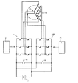
上記した高調波電流を発生する回路例を図3に示す。このモータ制御回路はモータ電流をフィードバック制御を行う実施例である。
(Circuit configuration example 1)
FIG. 3 shows an example of a circuit that generates the above harmonic current. This motor control circuit is an embodiment that performs feedback control of the motor current.
1はバッテリ、2、3は平滑コンデンサ、4は三相インバータである第1インバータ、5は三相インバータである第2インバータ、6は第1モータコントローラ、7は第2モータコントローラ、8は永久磁石ロータ型の三相同期モータである。モータ8は発電機又は発電電動機であってもよい。モータ8は、互いに独立する2つの三相スター接続電機子コイル81、82を有し、コイル81は本発明でいう第1相巻線群を、コイル82は本発明でいう第2相巻線群を構成している。
1 is a battery, 2 is a smoothing capacitor, 4 is a first inverter that is a three-phase inverter, 5 is a second inverter that is a three-phase inverter, 6 is a first motor controller, 7 is a second motor controller, and 8 is permanent This is a magnet rotor type three-phase synchronous motor. The
バッテリ1から直流電力が給電され、モータコントローラ6により制御される第1インバータ4はコイル81に第1の三相電機子電圧を印加し、第2モータコントローラ7により制御される第2インバータ5はコイル82に第2の三相電機子電圧を印加している。モータコントローラ6は、コイル81に通電される三相交流電流を検出する電流検出センサ(図示せず)から電流信号を、図示しない回転角検出器から回転角信号を受け取り、これらの信号と入力指令とに基づいて第1インバータ4を制御する。モータコントローラ7は、コイル82に通電される三相交流電流を検出する電流検出センサ(図示せず)から電流信号を、上記回転角検出器から回転角信号を受け取り、これらの信号と入力指令とに基づいて第2インバータ5を制御する。
DC power is supplied from the
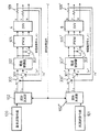
モータコントローラ6、7の一例を図4を参照して説明する。ただし、図4において、9は第1インバータ4とモータコントローラ6とからなる第1のモータ電流制御手段であり、10は第2インバータ5とモータコントローラ7とからなるモータ電流制御手段である。
An example of the
100は、基本波に相当する電流指令値(三相交流座標系)の振幅、位相を指示する振幅・位相指令用の回路ブロックである。101は、所定次数(ここでは7次)の高調波電流(三相交流座標系)の振幅、位相を指示する振幅・位相指令用の回路ブロックである。
振幅・位相指令用の回路ブロック100は、たとえば車両制御ECUなどの外部制御装置から受け取った電流指令(基本波)に基づいて上記振幅、位相を決定する。また、回路ブロック100がこの車両制御ECUにより構成されてもよい。この外部制御装置は三相同期機8の回転角信号(回転位置信号)及びトルク指令に基づいてこの基本波としての電流指令値を演算する。
The amplitude / phase
回路ブロック101は、上記した電流指令(基本波)電流の周波数、振幅、位相を上記した数35、数36、数37や数13又は数14又は数15に入力して演算することにより、あらかじめ定められた所定次数の高調波電流の周波数、振幅、位相を決定し、それらを指示する振幅・位相指令を出力する。これら数式のうちの他の定数は目的に応じて予め設定されている。たとえば、6次及び12次の磁気音を低減又はキャンセルする場合には、数36、数37の式の計算値が所定値以下又は0となるように、7次又は13次の高調波電流の振幅と位相とを決定する。他の定数は交流回転電機に特有の数値として予め設定されている。6次の磁気音だけをキャンセルする場合には、数36の式の計算値が所定値以下又は0となるように、高調波電流の振幅と位相とを決定する。12次の磁気音だけをキャンセルする場合には、数37の式の計算値が所定値以下又は0となるように、高調波電流の振幅と位相とを決定する。いずれにせよ、これらの式において、重畳する7次及び/又は13次の高調波電流の位相及び/振幅を調整することにより、6次/又は12次の磁気音すなわち磁気音の大部分を増幅したり、低減したり、キャンセルしたりすることができる。上記数式の計算の代わりに、予めこれらの数式に相当するマップ又はテーブルに上記基本周波数成分の周波数、位相、振幅を代入して、7次及び/又は13次の高調波電流の位相、振幅の値をサーチしてもよい。また、回路ブロック100が、演算されたステータ電流の基本周波数成分の振幅及び位相に基づいてその現在値を算出して出力し、回路ブロック101が、演算された高調波電流の振幅及び位相に基づいて高調波電流の現在値を算出して出力することもできる。
The
これら基本波電流及び高調波電流に関する指令は、座標軸変換用の回路ブロック103、103’によりd−q軸系に座標変換され、減算器104、104’にてそれらの検出値(d−q軸)と比較され、それらの差が電流増幅器400、400’によりゲイン調節された後、座標軸変換用の回路ブロック105、105’にて三相交流電流値に出力される。
The commands related to the fundamental wave current and the harmonic current are coordinate-converted into the dq axis system by the coordinate axis conversion circuit blocks 103 and 103 ′, and the detected values (dq axis) are subtracted by the
回路ブロック105、105’から出力される三相交流電流値は、回路ブロック106、106’にて三相PWM制御電圧に変換され、これら三相PWM制御電圧により三相のインバータ4、5の各スイッチング素子を断続制御し、インバータ4の出力電圧を第1相巻線群81に、インバータ5の出力電圧を第2相巻線群82に印加する。
The three-phase alternating current values output from the circuit blocks 105 and 105 ′ are converted into three-phase PWM control voltages by the circuit blocks 106 and 106 ′, and each of the three-
なお、第1相巻線群81との各導体と第2相巻線群82の各導体とを同じスロットに収容して、これら第1相巻線群81と第2相巻線群82との位相差を0としてもよく、あるいは、両導体を周方向に所定スロットピッチずらして位相差を与えてもよいことは当然である。これにより、第1相巻線群81には基本波電流が、第2相巻線群にはたとえば7次の高調波電流が流れることになる。
Each conductor of the first
三相同期機8は回転角センサを内蔵しており、速度・位置信号処理用回路ブロック107は、図示しない回転角センサから出力されるロータの回転位置信号から速度信号と位置信号とを抽出し、それらを回路ブロック103、103’、105、105’に出力する。また、第1相巻線群81、第2相巻線群82の各相電流は、電流センサ109、109’にて検出され、座標軸変換用回路ブロック108、108’にてd軸電流検出値とq軸電流検出値とに変換されて減算器104、104’に入力されて電流値を指令値に収束させるフィードバック制御が行われる。なお、202は次数発生回路ブロックであって、座標変換ブロック103’、105’に発生するべき高調波成分の次数を指示する機能を有している。
The three-phase
このようにすることにより、三相同期機8に与えるモータ電流の基本周波数成分と高調波成分とを別々に制御することができるので、回路信頼性を高め、特に、トルクを実現する基本周波数成分の制御レスポンスおよび制御信頼性を向上しつつ、磁気騒音を低減して非常に静粛なモータを実現することができる。また、基本相電流制御を低周波数で行うことができるので、その回路負担を減らすことができる。
By doing so, the fundamental frequency component and the harmonic component of the motor current applied to the three-phase
(回路構成例2)
上記した高調波電流を発生する他の回路例を図5に示す。この回路は、図4に示す回路をオープン制御に変更したものである。
(Circuit configuration example 2)
Another circuit example for generating the above harmonic current is shown in FIG. This circuit is obtained by changing the circuit shown in FIG. 4 to open control.
基本波回路ブロック100、高調波回路ブロック101から出力される基本波電流及び高調波電流に関する指令は、座標軸変換用の回路ブロック103、103’によりd−q軸系に座標変換され、電流増幅器400、400’によりゲイン調節された後、座標軸変換用の回路ブロック105、105’にて三相交流電流値に出力される。
The commands related to the fundamental wave current and the harmonic current output from the fundamental
回路ブロック106、106’は、入力される三相交流電流値に対応する三相PWM制御電圧を発生させ、これら三相PWM制御電圧により三相インバータ4、5のスイッチング素子は断続制御される。三相同期機8は回転角センサを内蔵しており、速度・位置信号処理用回路ブロック107は、この回転角センサから出力される回転位置信号から速度信号と位置信号とを抽出し、座標変換のために回路ブロック103、103’、105、105’へそれらを出力する。これにより、回路構成例1と同様の効果を奏することができる。
The circuit blocks 106 and 106 'generate a three-phase PWM control voltage corresponding to the input three-phase AC current value, and the switching elements of the three-
(回路構成例3)
上記した高調波電流を発生する他の回路例を図6に示す。この回路例は三相交流座標系にてモータ電流をフィードバック制御を行う実施例である。
(Circuit configuration example 3)
Another circuit example for generating the above harmonic current is shown in FIG. This circuit example is an embodiment in which the motor current is feedback controlled in a three-phase AC coordinate system.
100は、基本波に相当する電流指令値(三相交流座標系)としての振幅、位相を指示する振幅・位相指令用の回路ブロックである。101は、所定次数の高調波電流(三相交流座標系)としての振幅、位相を指示する振幅・位相指令用の回路ブロックである。これらの回路ブロックの機能は、図3の場合と同じであり、高調波ブロック101は、回路ブロックから出力される周波数、位相、振幅を数35又は数36又は数37や数13又は数14又は数15に代入して高調波の振幅、位相を決定するか、実質的に同じ演算処理をマップ又はテーブルを用いて行う。
回路ブロック100、101から出力された振幅・位相指令は、回路ブロック102、102’に入力される。回路ブロック102は、入力された基本波の振幅・位相指令と、検出された回転位置信号とに基づいて基本波電流指令値(三相交流座標系)を形成し、回路ブロック102’は、入力された所定次数の高調波の振幅・位相指令と、検出された回転位置信号とに基づいて高調波電流指令値(三相交流座標系)を形成する。
The amplitude / phase commands output from the circuit blocks 100 and 101 are input to the circuit blocks 102 and 102 '. The
減算器300は、検出された基本波U相電流検出値iu’と基本波電流指令値iuとの差を求め、この差を電流制御器をなす回路ブロック302に出力する。減算器301は、検出された基本波V相電流検出値iv’と基本波電流指令値ivとの差を求め、この差を電流制御器をなす回路ブロック302に出力する。回路ブロック302は上記差を解消するU相電圧、V相電圧を形成し、回路ブロック105はこれらU相電圧、V相電圧に相当するU相、V相のPWM電圧を演算出力する。また、減算反転回路303は、上記U相電圧、V相電圧の差のアナログ反転信号をW相電圧として算出し、回路ブロック105はこのW相電圧のPWM電圧を演算出力する。これら三相のPWM電圧に相当するデユーティに応じて第1インバータ4が断続制御される。
The
減算器300’は、検出された高調波U相電流検出値iu’と高調波電流指令値iuとの差を求め、この差を電流制御器をなす回路ブロック302’に出力する。減算器301’は、検出された高調波V相電流検出値iv’と高調波電流指令値ivとの差を求め、この差を電流制御器をなす回路ブロック302’に出力する。回路ブロック302’は上記差を解消するU相電圧、V相電圧を形成し、回路ブロック105’はこれらU相電圧、V相電圧に相当するU相、V相のPWM電圧を演算出力する。また、減算反転回路303’は、上記U相電圧、V相電圧の差のアナログ反転信号をW相電圧として算出し、回路ブロック105’はこのW相電圧のPWM電圧を演算出力する。これら三相のPWM電圧に相当するデユーティに応じて第2インバータ5が断続制御される。
(変形態様)
上記した回路例の他、種々の公知モータ制御回路を採用できることは当然である。また、基本波形成用のモータコントローラ6と、高調波形成用のコントローラ7とは全く異なる回路としてもよく、また、クロック周波数が異なるようにしてもよい。たとえば、モータコントローラ6は高精度フィードバック回路とし、モータコントローラ7はオープン制御回路としてもよい。
(変形態様)
上記各回路例の変形態様を図7に示すフローチャートを参照して以下に説明する。この変形態様は、必要電流(必要トルク)と回転数とに基づいて第2インバータの動作モードを変更するものである。
The
(Modification)
In addition to the circuit examples described above, various known motor control circuits can naturally be employed. Further, the fundamental wave forming
(Modification)
A modification of each circuit example will be described below with reference to a flowchart shown in FIG. In this modification, the operation mode of the second inverter is changed based on the required current (required torque) and the rotational speed.
まず、外部より入力されるトルク指令値(又は電流指令値)と回転数検出値とを読み込む(ステップS100、S102)。これら指令値が所定レベル未満かつ回転数が所定値未満である場合にはたとえば図3に示す次数発生回路ブロック202の出力次数を変更することにより、第2インバータを所定次数n+1の高調波電流を発生するように運転する。もちろん、この時、n次の径方向振動が低減されるようにこの高調波電流の振幅と位相とが決定される。これら指令値が所定レベル以上又は回転数が所定値以上である場合にはたとえば図4に示す次数発生回路ブロック202の出力次数を変更することにより、2つのインバータをそれぞれ基本波電流のみを発生するように運転する(ステップS104)。磁気騒音が問題となるのは、低回転領域であるので、損失低下、大トルク出力、磁気騒音低下の効果をバランスよく実現することができる。
(変形態様)
なお、数35、数36、数37の式は、ロータ起磁力Fmagの高調波成分をステータ電流の基本波電流への高調波電流の重畳によりキャンセル乃至変更する例を示しているが、実際の交流回転電機のPWM制御では、インバータのスイッチングにより基本波電流に不可避的に高調波が重畳し、これに起因して磁気音が生じる。この磁気音を更に減少するには、このインバータのスイッチングによりステータ電流に不可避的に重畳する高調波電流を上記数式で求めた磁気音変更用の高調波電流からベクトル減算した高調波電流を基本波電流に重畳する演算を行えばよい。
First, a torque command value (or current command value) and a rotation speed detection value input from the outside are read (steps S100 and S102). When these command values are less than a predetermined level and the rotation speed is less than a predetermined value, for example, by changing the output order of the order
(Modification)
Note that the equations of Equations 35, 36, and 37 show examples in which the harmonic component of the rotor magnetomotive force Fmag is canceled or changed by superimposing the harmonic current on the fundamental current of the stator current. In PWM control of an AC rotating electrical machine, harmonics are inevitably superimposed on the fundamental current due to switching of the inverter, resulting in magnetic noise. In order to further reduce this magnetic noise, the harmonic current obtained by subtracting the harmonic current inevitably superimposed on the stator current by switching of this inverter from the harmonic current for changing the magnetic sound obtained by the above formula is fundamental. A calculation to be superimposed on the current may be performed.
(実験例)
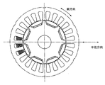
上記磁気騒音低減のための実験を図8に示す三相同期機(8極、24スロット、IPM)14を用いて行った。なお、基本波電流を43Aとし、ロータ位相角はトルクが最大となる値に制御した。
(Experimental example)
The experiment for reducing the magnetic noise was performed using a three-phase synchronous machine (8 poles, 24 slots, IPM) 14 shown in FIG. The fundamental current was 43 A, and the rotor phase angle was controlled to a value that maximized the torque.
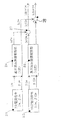
図9は、この同期機のステータ電流に磁気騒音低減用の高調波電流を重畳せずにモータ駆動した場合の三相電流波形を示す。各相電流は、その基本周波数成分の他に比較的小さい高調波成分を含んでいる。図10は、図9に示すステータ電流に磁気騒音低減用の高調波電流を重畳してモータ駆動した場合の三相電流波形を示す。図9、図10において、回転数は17000rpmとした。磁気騒音低減用の高調波電流は、図3の回路を用いてフィードバック方式にて重畳された。 FIG. 9 shows a three-phase current waveform when the motor is driven without superimposing a harmonic current for reducing magnetic noise on the stator current of the synchronous machine. Each phase current includes a relatively small harmonic component in addition to its fundamental frequency component. FIG. 10 shows a three-phase current waveform when the motor is driven by superimposing a harmonic current for reducing magnetic noise on the stator current shown in FIG. 9 and 10, the rotation speed was 17000 rpm. The harmonic current for magnetic noise reduction was superimposed by a feedback method using the circuit of FIG.
それぞれFFTにより求めた図9に示すU相電流の周波数スペクトルA、及び、図10に示す磁気騒音低減用高調波成分重畳U相電流の周波数スペクトルBを、図11に示す。図11において、各次数ごとに示された一対のバーのうち左側(薄いグレーにて表示)は図9に示すU相電流のスペクトルAを示し、各次数ごとに示された一対のバーのうち右側(濃いグレーにて表示)は図10に示すU相電流のスペクトルBを示す。図9において、7次電流(7次高調波成分)は1次電流(基本周波数成分)の振幅の3%の大きさの振幅を有している。図10において、7次電流(7次高調波成分)は1次電流(基本周波数成分)の振幅の12%の大きさの振幅を有している。 FIG. 11 shows the frequency spectrum A of the U-phase current shown in FIG. 9 and the frequency spectrum B of the harmonic component superimposed U-phase current for reducing magnetic noise shown in FIG. In FIG. 11, the left side (displayed in light gray) of the pair of bars shown for each order shows the spectrum A of the U-phase current shown in FIG. 9, and the pair of bars shown for each order The right side (displayed in dark gray) shows the spectrum B of the U-phase current shown in FIG. In FIG. 9, the seventh current (seventh harmonic component) has an amplitude that is 3% of the amplitude of the primary current (fundamental frequency component). In FIG. 10, the seventh current (seventh harmonic component) has an amplitude of 12% of the amplitude of the primary current (fundamental frequency component).
図9の電流を通電した場合(以下、磁気騒音非低減モードと言う)と図10の電流を通電した場合(以下、磁気騒音低減モードと言う)とにおけるステータの互いに隣接する3個のティースに加わる半径方向(径方向)加振力のロータ回転角による変化を図12に示す。図12に示される二つの周期変化波形のうち大きな方の周期変化波形Cは図9に示す磁気騒音非低減モードの径方向加振力の変化を示し、小さい方の周期変化波形Dは図10に示す磁気騒音非低減モードの径方向加振力の変化を示す。また、Eは、磁気騒音非低減モードにおける径方向加振力の平均値を示す。なお、径方向加振力はロータの永久磁石の吸引により直流成分を有している。 The three adjacent teeth of the stator when the current of FIG. 9 is applied (hereinafter referred to as a magnetic noise non-reduction mode) and when the current of FIG. 10 is applied (hereinafter referred to as a magnetic noise reduction mode). FIG. 12 shows changes in the applied radial direction (radial direction) excitation force depending on the rotor rotation angle. The larger period change waveform C of the two period change waveforms shown in FIG. 12 shows the change in the radial excitation force in the magnetic noise non-reduction mode shown in FIG. 9, and the smaller period change waveform D shows the change in the period change waveform D in FIG. Changes in the radial excitation force in the magnetic noise non-reduction mode shown in FIG. E represents the average value of the radial excitation force in the magnetic noise non-reduction mode. The radial excitation force has a direct current component due to the attraction of the permanent magnet of the rotor.
図13において、Fは示す磁気騒音非低減時の径方向加振力(大きい周期変化波形)Cの周波数スペクトルを示し、Gは磁気騒音低減時の径方向加振力(小さい周期変化波形)Dの周波数スペクトルを示す。周波数スペクトルFは、各次数ごとに示された一対のバーのうち左側(薄いグレーにて表示)のバーにより示されている。周波数スペクトルGは、各次数ごとに示された一対のバーのうち右側(濃いグレーにて表示)のバーにより示されている。 In FIG. 13, F indicates the frequency spectrum of the radial excitation force (large periodic variation waveform) C when magnetic noise is not reduced, and G indicates the radial excitation force (small periodic variation waveform) D when magnetic noise is reduced. The frequency spectrum of is shown. The frequency spectrum F is indicated by a bar on the left side (displayed in light gray) among a pair of bars indicated for each order. The frequency spectrum G is indicated by a bar on the right side (displayed in dark gray) of a pair of bars indicated for each order.
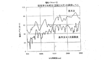
上記実験機における回転数を変更した場合の6次の磁気音(周波数6θ)の測定結果(電動時)を図14に示す。図14から、磁気騒音が耳障りとなる高回転域(約1500rpm以上)にて良好に磁気騒音の6次成分を低減できることがわかる。上記実験機における回転数を変更した場合の6次の磁気音(周波数6θ)の測定結果(発電時)を図15に示す。図15から、ほとんど全部の回転域にわたって磁気騒音の6次成分を低減できることがわかる。また、磁気騒音が最大となる回転域において、磁気騒音低減用の高調波電流の重畳により6次磁気騒音を20dbも低減できることがわかる。なお、図14、図15において一部の回転域において6次の磁気騒音は、磁気騒音低減用の高調波電流の7次成分の重畳により増加しているが、これは制御定数の設定が最適化されていないためであり、本質的なものではない。また、この磁気騒音の逆転は、6次の磁気騒音のレベルが小さいレベルで発生しており、その絶対値も小さいため問題とはならない。もちろん、この同期機において、磁気騒音低下があまり期待できない回転域において、磁気騒音低減用の7次の高調波電流の重畳を停止することもできる。 FIG. 14 shows the measurement result (during electric operation) of the sixth-order magnetic sound (frequency 6θ) when the rotation speed in the experimental machine is changed. From FIG. 14, it can be seen that the 6th-order component of magnetic noise can be satisfactorily reduced in a high rotation range (about 1500 rpm or more) in which magnetic noise is annoying. FIG. 15 shows the measurement results (during power generation) of the sixth-order magnetic sound (frequency 6θ) when the rotation speed in the experimental machine is changed. FIG. 15 shows that the sixth-order component of magnetic noise can be reduced over almost the entire rotation range. It can also be seen that the sixth-order magnetic noise can be reduced by 20 db by superimposing the harmonic current for reducing the magnetic noise in the rotation region where the magnetic noise is maximum. 14 and 15, the sixth-order magnetic noise increases in some rotation regions due to the superposition of the seventh-order component of the harmonic current for magnetic noise reduction. This is because it is not realized, and is not essential. Further, the reversal of the magnetic noise occurs at a level where the sixth-order magnetic noise level is small, and the absolute value thereof is small, so that there is no problem. Of course, in this synchronous machine, the superimposition of the seventh harmonic current for magnetic noise reduction can be stopped in the rotation range where the reduction in magnetic noise cannot be expected so much.
(変形態様)
なお、上記実施例の回路による高調波の重畳技術を利用して、すなわち周方向振動より次数が1大きい高調波電流を基本周波数成分に重畳することにより
、磁気騒音低減をやめて必要に応じてトルクリップル低減を行うように切り替えることもできる。具体的には、高調波電流の振幅と位相角を変更すればよい。
(Modification)
In addition, by using the harmonic superposition technique by the circuit of the above embodiment, that is, by superimposing a harmonic current having a higher order than the circumferential vibration on the fundamental frequency component, the magnetic noise reduction is stopped and the torque is adjusted as necessary. It can also be switched to reduce ripple. Specifically, the amplitude and phase angle of the harmonic current may be changed.
(変形態様)
数35、数36、数37の式は、ロータ起磁力Fmagの高調波成分をステータ電流の基本波電流への高調波電流の重畳によりキャンセル乃至変更する例を示しているが、実際の交流回転電機のPWM制御では、インバータのスイッチングにより基本波電流に不可避的に高調波が重畳し、これに起因して磁気音が生じる。この磁気音を更に減少するには、このインバータのスイッチングによりステータ電流に不可避的に重畳する高調波電流を上記数式で求めた磁気音変更用の高調波電流からベクトル減算した高調波電流を基本波電流に重畳する演算を行えばよい。
(Modification)
Equations 35, 36, and 37 show examples in which the harmonic component of the rotor magnetomotive force Fmag is canceled or changed by superimposing the harmonic current on the fundamental current of the stator current. In the PWM control of an electric machine, harmonics are inevitably superimposed on the fundamental current due to switching of the inverter, resulting in magnetic noise. In order to further reduce this magnetic noise, the harmonic current obtained by subtracting the harmonic current inevitably superimposed on the stator current by switching of this inverter from the harmonic current for changing the magnetic sound obtained by the above formula is fundamental. A calculation to be superimposed on the current may be performed.
(変形態様)
上記磁気騒音低減方式の回転電機をエンジン走行車両に搭載した場合の制御動作を図16に示すフローチャートを参照して説明する。なお、この種の回転電機は、たとえばハイブリッド車やトルクアシスト車用の発電電動機や電動エアコン等として広く用いられ、周知となっている。
(Modification)
A control operation when the magnetic noise reduction type rotating electrical machine is mounted on an engine traveling vehicle will be described with reference to a flowchart shown in FIG. In addition, this kind of rotary electric machine is widely used as, for example, a generator motor or an electric air conditioner for a hybrid vehicle or a torque assist vehicle, and is well known.
まず、ステップS400にて、エンジン停止中で電動動作中か、又は、回生制動による発電中かどうかを調べ、そうであれば、径方向振動低減用の第二インバータを運転し(S402)、そうでなければこの第2インバータを運転しない(S404)。この第2インバータは、7次および13次の高調波電流をそれぞれ所定位相、所定振幅で重畳する。この7次の高調波電流の位相、振幅は、この重畳により、三相交流回転電機の本来の径方向磁気加振力(磁気音)の6次高調波成分を上述の式に基づいてキャンセルする大きさに設定される。これにより、エンジン騒音が存在せず発電電動機の磁気騒音が耳障りとなりやすいエンジン停止中における、又は、エンジン回転数が低くエンジン騒音が耳障りとなりやすい回生制動(発電)中の磁気騒音を低減して車両静粛性を向上することができる。また、それ以外の運転時には、高調波電流重畳制御用の回路を休止させることができる。 First, in step S400, it is checked whether the engine is stopped and the electric operation is being performed, or whether the power is being generated by regenerative braking. If so, the second inverter for reducing radial vibration is operated (S402). Otherwise, the second inverter is not operated (S404). The second inverter superimposes the 7th and 13th harmonic currents with a predetermined phase and a predetermined amplitude, respectively. The phase and amplitude of the seventh-order harmonic current cancels the sixth-order harmonic component of the original radial magnetic excitation force (magnetic sound) of the three-phase AC rotating electric machine based on the above formula. Set to size. This reduces the magnetic noise during regenerative braking (power generation) when the engine is stopped, where there is no engine noise and the magnetic noise of the generator motor tends to be harsh, or when the engine speed is low and the engine noise tends to be harsh. Silence can be improved. Further, during other operations, the harmonic current superimposing control circuit can be suspended.
なお、ステップS404において、第1インバータと協同して基本波を発生させる運転を第2インバータに指令してもよい。このようにすれば、一つのインバータの電流量が半減するためインバータ損失を低減して効率向上を図ることができる。 In step S404, the second inverter may be instructed to generate a fundamental wave in cooperation with the first inverter. In this way, since the current amount of one inverter is halved, it is possible to reduce the inverter loss and improve the efficiency.
以上、本発明の好適な実施態様について詳述したが、当業者が種々の修正及び変更をなし得ること、並びに、特許請求の範囲は本発明の真の精神および趣旨の範囲内にあるこの様な全ての修正及び変更を包含することは、本発明の範囲に含まれることは当業者に理解されるべきものである。 Although preferred embodiments of the present invention have been described in detail above, various modifications and changes can be made by those skilled in the art, and the scope of the claims falls within the true spirit and scope of the present invention. It is to be understood by those skilled in the art that all such modifications and changes are included in the scope of the present invention.
(参考例)
重畳する高調波電流の制御参考例を、図17〜図20を参照して説明する。図17はこの実施例のモータ制御装置を示すブロック回路図、図18は座標変換回路2の一例を示すブロック回路図、図19は回路各部の信号波形(回転座標系表示)を示す波形図、図20は回路各部の信号波形(静止座標系表示)を示す波形図である。
(Reference example)
A control reference example of the superimposed harmonic current will be described with reference to FIGS. FIG. 17 is a block circuit diagram showing the motor control device of this embodiment, FIG. 18 is a block circuit diagram showing an example of the coordinate
このモータ制御装置はモータ電流をフィードバック制御を行う実施例であって、1は基本波指令値発生回路、2は高調波指令値発生回路、3、4は加算器、5、6は減算器、7、8はPIアンプ(比例−積分回路)、9は座標変換回路、10はPWM電圧発生回路、11は三相インバータ、12は2つの電流センサ(相電流検出要素)、13は三相同期電動発電機(車両用同期交流回転電機)、14はレゾルバ(回転角検出要素)、15は位置信号処理回路、16は遅れ補償回路、17は座標変換回路である。 This motor control device is an embodiment for performing feedback control of motor current, wherein 1 is a fundamental wave command value generation circuit, 2 is a harmonic command value generation circuit, 3 and 4 are adders, 5 and 6 are subtractors, 7 and 8 are PI amplifiers (proportional-integral circuits), 9 is a coordinate conversion circuit, 10 is a PWM voltage generation circuit, 11 is a three-phase inverter, 12 is two current sensors (phase current detection elements), and 13 is three-phase synchronous. A motor generator (synchronous AC rotating machine for vehicles), 14 is a resolver (rotation angle detecting element), 15 is a position signal processing circuit, 16 is a delay compensation circuit, and 17 is a coordinate conversion circuit.
上記各構成要素1〜17のうち三相同期電動発電機13を除く構成要素は、本発明で言うモータ制御装置を構成しており、上記各構成要素1〜17のうち電流センサ(相電流検出要素)12、三相同期電動発電機(車両用同期交流回転電機)13およびレゾルバ(回転角検出要素)をのぞく構成要素(回路)は、本発明で言うモータ電流制御要素又はモータ制御手段を構成している。
Of the
また、構成要素(回路)17は本発明で言う相電流検出値座標系変換要素を構成し、構成要素(回路)1は本発明で言う基本波指令値出力要素を構成し、構成要素(回路)2は本発明で言う高調波指令値出力要素を構成し、構成要素(回路)3〜6は本発明で言う電流偏差演算要素を構成し、構成要素(回路)7〜11は本発明で言う相電圧制御要素を構成している。いうまでもなく、三相インバータ11は直流電源から給電されて三相交流電圧を発生する。
The component (circuit) 17 constitutes a phase current detection value coordinate system conversion element referred to in the present invention, and the component (circuit) 1 constitutes a fundamental wave command value output element referred to in the present invention. ) 2 constitutes a harmonic command value output element referred to in the present invention, components (circuits) 3 to 6 constitute current deviation calculation elements referred to in the present invention, and components (circuits) 7 to 11 represent the present invention. This constitutes the phase voltage control element. Needless to say, the three-
基本波指令値発生回路(基本波指令値出力要素)1は、入力されるトルク指令値および回転数指令値に対応する基本波電流の目標値を、そのd軸電流成分であるd軸基本波指令値Id1*、および、そのq軸電流成分であるq軸基本波指令値Iq1*に変換する公知の回路である。上記トルク指令値は、たとえば車両制御ECUなどの外部制御装置から入力され、この基本波指令値発生回路1はそれにも基づいてd軸基本波指令値Id1*およびq軸基本波指令値Iq1*を決定する。このd軸基本波指令値Id1*およびq軸基本波指令値Iq1*の決定において必要であれば、トルク指令値以外に更に三相インバータ11の電圧やレゾルバ14の出力信号などが基本波指令値発生回路1に入力される。
A fundamental wave command value generation circuit (fundamental wave command value output element) 1 sets a target value of a fundamental wave current corresponding to an input torque command value and a rotational speed command value, and a d-axis fundamental wave that is a d-axis current component. This is a known circuit that converts the command value Id1 * and the q-axis fundamental wave command value Iq1 * that is the q-axis current component thereof. The torque command value is input from, for example, an external control device such as a vehicle control ECU, and the fundamental wave command
高調波指令値発生回路2(高調波指令値出力要素)は、あらかじめ設定された6k+1(kは整数、基本周波数成分のkは0)次の高調波電流の目標値を、そのd軸電流成分であるd軸高調波指令値Id6k+1*、および、そのq軸電流成分であるq軸高調波指令値Iq6k+1*に変換する回路である。更に言えば、この高調波指令値発生回路2は、三相同期電動発電機13の径方向振動を低減する高調波電流指令値を発生するための回路である。
The harmonic command value generation circuit 2 (harmonic command value output element) is set to a preset target value of 6k + 1 (k is an integer, k of the fundamental frequency component is 0) and the d-axis current component. Is a d-axis harmonic command value Id6k + 1 * and a q-axis harmonic command value Iq6k + 1 * which is the q-axis current component. Furthermore, the harmonic command
高調波指令値発生回路2の具体例を図21に示すブロック図を参照して説明する。図21において、21は7次電流指令値発生回路、22は13次電流指令値発生回路、24、25は座標変換回路、27、28は加算器である。ただし、この実施例では、高調波指令値発生回路2は6次および12次の径方向振動低減のために7次および13次の高調波指令値だけを発生するが更に高次の高調波指令値を発生して加算器27、28にて同様に重畳させてもよい。
A specific example of the harmonic command
7次電流指令値発生回路21は、基本波指令値発生回路1から入力されるd軸指令値Id*およびq軸指令値Iq*と、6次径方向振動相殺用の7次高調波指令値の振幅I7*および位相角β7*との関係を記載するテーブルである。すなわち、7次高調波指令値の振幅I7*および位相角β7*は、基本波回転座標系上のd軸指令値Id*およびq軸指令値Iq*を変数とする関数値となる。なお、ここでは、7次高調波指令値の振幅I7*および位相角β7*は基本波回転座標系上の値とするが、静止座標系上においても同じ値となる。
The seventh-order current command
同じく、13次電流指令値発生回路22は、基本波指令値発生回路1から入力されるd軸指令値Id*およびq軸指令値Iq*と、12次径方向振動相殺用の13次高調波指令値の振幅I13*および位相角β13*との関係を記載するテーブルである。すなわち、13次高調波指令値の振幅I13*および位相角β13*は、基本波回転座標系上のd軸指令値Id*およびq軸指令値Iq*を変数とする関数値となる。なお、ここでは、13次高調波指令値の振幅I13*および位相角β13*は基本波回転座標系上の値とするが、静止座標系上においても同じ値となる。これらのデータI7*、β7*、I13*、β13*は7次、13次電流指令値発生回路21、22のROM(図示せず)に格納されている。d軸指令値Id*およびq軸指令値Iq*を回路21、22に代入して得られたこれらのデータI7*、β7*は座標変換回路24へ、これらのデータI13*、β13*は座標変換回路25に出力される。
Similarly, the 13th-order current command
座標変換回路24は、7次電流指令値発生回路21から入力された7次高調波電流の振幅I7*と位相角(基本波の位相角θを基準として決定する)β7*とにより基本波回転座標系(d−q軸座標系又は基本波dq座標系ともいう)表示の7次高調波電流指令値のd軸成分であるd軸高調波指令値Id7*、および、そのq軸成分であるq軸高調波指令値Iq7*を演算する。
The coordinate
座標変換回路25は、13次電流指令値発生回路22から入力された13次高調波電流の振幅I13*と位相角(基本波の位相角θを基準として決定する)β13*とにより基本波回転座標系(d−q軸座標系又は基本波dq座標系ともいう)表示の13次高調波電流指令値のd軸成分であるd軸高調波指令値Id13*、および、そのq軸成分であるq軸高調波指令値Iq13*を演算する。この演算は、次に示す数38の演算により行われる。
The coordinate
なお、数38において、θvは、後述する遅れ補償回路(位相補償回路)16から出力されるモータ回転角θを位相補償して得た位相補償回転角信号である。 In Equation 38, θv is a phase compensation rotation angle signal obtained by phase compensation of the motor rotation angle θ output from a delay compensation circuit (phase compensation circuit) 16 described later.
ただし、上記説明では、回路21、22は、d軸指令値Id*、q軸指令値Iq*と出力すべき高調波指令値の振幅、位相角とのテーブルを記憶したが、この検出した回転角、電圧、電流と、出力すべき高調波指令値の振幅、位相角とのテーブルを記憶しておき、このテーブルに回転角、電圧、電流の検出値を代入して出力すべき高調波指令値の振幅、位相角を演算してもよい。
However, in the above description, the
次に、7次d軸高調波指令値Id7*と13次d軸高調波指令値Id13*とは加算器27により加算されてd軸高調波指令値Id6n+1*とされ、7次q軸高調波指令値Iq7*と13次q軸高調波指令値Iq13*とは加算器28により加算されてq軸高調波指令値Iq6n+1*とされる。もちろん、19次高調波指令値など更に高次の高調波指令値を形成して加算器27、28にて同様に加算してもよい。
Next, the seventh-order d-axis harmonic command value Id7 * and the thirteenth-order d-axis harmonic command value Id13 * are added by the
このようにして求めたd軸高調波指令値Id6n+1*は加算器3によりd軸基本波指令値Id1*に加算されてd軸指令値Id*とされ、同様に、q軸高調波指令値Iq6n+1*は加算器4によりq軸基本波指令値Iq1*に加算されてq軸指令値Iq*とされる。これにより、簡単な演算により騒音キャンセル電流指令値を決定することができる。すなわち、各次高調波指令値は数38に示すように単一周波数成分だけを演算すればよいので簡単となる。
The d-axis harmonic command value Id6n + 1 * thus obtained is added to the d-axis fundamental wave command value Id1 * by the
位置信号処理回路15は、レゾルバ14からの回転角信号に基づいて静止座標
系の回転角θを演算し、遅れ補償回路16および座標変換回路17に出力する。遅れ補償回路16は、位相補償回路であって、位相補償された回転角θvを座標変換回路24、25および後述する座標変換回路9に出力し、これらの回路の演算遅れなどを補償する。座標変換回路17は、電流センサ12で検出されたU相電流IuとV相電流Ivとを座標変換処理することにより、回転座標系表示の電流検出値としてのd軸検出値Idとq軸検出値Iqとを出力する。
The position
減算器5は、上記の演算により求められたd軸指令値Id*からd軸検出値Idを減算して偏差ΔIdを求め、減算器6は、q軸指令値Iq*からq軸検出値Iqを減算して偏差ΔIqを求める。PIアンプ7は、偏差ΔIdを0に収束させるべく偏差ΔIdをPI(比例−積分)増幅して対応するd軸電圧Vdを出力し、PIアンプ8は、偏差ΔIqを0に収束させるべく偏差ΔIqをPI(比例−積分)増幅して対応するq軸電圧Vqを出力する。
The
座標変換回路9は、入力される位相補償回転角信号θvを用いてこれらの電圧Vd、Vqを回転座標系の三相交流電圧Vu、Vv、Vwに変換し、PWM電圧発生回路10は三相交流電圧Vu、Vv、VwをPWM信号電圧Uu、Uv、Uwに変換し、三相インバータ11は入力されるPWM信号電圧Uu、Uv、Uwに基づいて内蔵の6つのスイッチング素子を断続制御して三相交流電圧を作成し、それを三相同期電動発電機13の各相端子に印加する。上記したモータ制御回路は、高調波指令値発生回路2をのぞいて通常のモータ制御方式と同じであり、この種のPWMフィードバック制御自体はもはや周知であるので、詳細な説明は省略する。これにより、モータにおいて騒音の主要要因となっている6次、12次高調波騒音のレベルを大幅に低減することができる。
(変形態様)
上記した数式を用いた説明では、3、5、7次高調波を含むロータ起磁力Fmagにより生じる6次、12次の磁気音を7次、13次の高調波電流成分の重畳によりキャンセル又は低減する場合を示した。上記と同様の計算を行った結果、ある次数の高調波電流を重畳することにより、少なくともこの次数より1だけ低い次数の磁気騒音、もしくは、この次数より1だけ低い次数の磁気騒音と他の次数の磁気騒音とを低減乃至キャンセルできることがわかった。
The coordinate
(Modification)
In the explanation using the above formula, the 6th and 12th magnetic sounds generated by the rotor magnetomotive force Fmag including the 3rd, 5th and 7th harmonics are canceled or reduced by superimposing the 7th and 13th harmonic current components. Shown when to do. As a result of performing the same calculation as described above, by superimposing a harmonic current of a certain order, magnetic noise having an order lower than this order by at least 1 or magnetic noise having an order lower by 1 than this order and other orders It was found that the magnetic noise can be reduced or canceled.
たとえば、上記と同様の演算により、18次の磁気音を19次の高調波電流成分の重畳により、24次の磁気音を25次の高調波電流成分の重畳によりキャンセル又は低減することができる。その他、上記説明した式において、6次の磁気音(磁気音)だけをキャンセル乃至低減することもでき、12次のそれだけをキャンセル乃至低減することも、数26、数27、数28の該当項を0とすることにより簡単に実施することができる。これらの結果、三相回転電機において支配的な磁気騒音である6、12、18、24次の磁気騒音を良好に低減することができる。 For example, the 18th-order magnetic sound can be canceled or reduced by superimposing the 19th-order harmonic current component and the 24th-order magnetic sound can be canceled or reduced by superimposing the 25th-order harmonic current component by the same calculation as described above. In addition, in the above-described formula, only the 6th-order magnetic sound (magnetic sound) can be canceled or reduced, and only the 12th-order magnetic sound can be canceled or reduced. It can be easily implemented by setting 0 to 0. As a result, it is possible to satisfactorily reduce the 6th, 12th, 18th, and 24th order magnetic noise, which is the dominant magnetic noise in the three-phase rotating electric machine.
また、上記数式を用いた説明では、理論説明をわかりやすくするために本来のステータ(電機子電流)としては基本周波数成分だけを想定し、この基本周波数成分にm次、n次の磁気騒音低減用の高調波電流を重畳すると考えた。しかし、一般的に(この実施例の制御を行わない場合)、実際のステータ電流にはロータ起磁力と同様に高調波成分を含むので、数16、数17、数18のステータ電流は、例としてj次、k次、L次を含んだ場合、数39、数40、数41のように表される。従って、これを前述の数式により展開すればロータ起磁力の高調波成分により発生した加振力と同様、元来含有する高調波電流による加振力が発生することは明らかである。従って、本発明で重畳する高調波電流はそれを踏まえて、次数、振幅、位相を決定することで磁気音を低減あるいはキャンセルすることが可能であることは当然である。(これらの数式展開は前述の各式にあてはめてみれはわかるため省略する。)
Further, in the explanation using the above mathematical formulas, only the fundamental frequency component is assumed as the original stator (armature current) for easy understanding of the theoretical explanation, and m-order and n-order magnetic noise reduction is applied to this fundamental frequency component. It was thought that the harmonic current for use would be superimposed. However, in general (when the control of this embodiment is not performed), since the actual stator current includes a harmonic component as well as the rotor magnetomotive force, the stator currents of
本来の電機子電流に含まれる高調波電流の次数が低減すべき径方向振動の高調波成分の次数より一つだけ大きい次数である場合には、上記数式にて演算した磁気騒音低減用の高調波電流からこの本来の電機子電流に含まれる高調波電流を減算して本来の電機子電流の基本周波数成分に重畳することが好適である。 When the order of the harmonic current included in the original armature current is one order higher than the order of the harmonic component of the radial vibration to be reduced, the harmonic for magnetic noise reduction calculated by the above formula is used. It is preferable to subtract the harmonic current contained in the original armature current from the wave current and superimpose it on the fundamental frequency component of the original armature current.
また、三相交流回転電機とは異なる多相交流回転電機であっても、ある次数の高調波電流を重畳することにより、この次数より1だけ低い次数の磁気音(磁気音)を低減できるという知見が成立することは、上記各式を相変更に合わせて変更すればわかるであろう。 Further, even in a multi-phase AC rotating electric machine different from a three-phase AC rotating electric machine, it is possible to reduce a magnetic sound (magnetic sound) of an order lower than this order by superimposing a harmonic current of a certain order. It will be understood that the above knowledge is established by changing each of the above equations in accordance with the phase change.
また、分布巻きと呼ばれる多スロット構成(たとえば毎相毎極2スロット以上の構成)においても、この実施例を適用することができることは当然である。 Further, it is natural that this embodiment can be applied to a multi-slot configuration called distributed winding (for example, a configuration having two or more slots per pole per phase).
上記した説明では、ステータ電流Icoilとして静止座標軸(角度θ)を基準に説明を行ったが、ステータ電流Icoilとして回転座標系(d、q軸)を基準として表示することも当然可能である。 In the above description, the stator current Icoil is described with reference to the stationary coordinate axis (angle θ). However, it is naturally possible to display the stator current Icoil with reference to the rotating coordinate system (d, q axes).
その他、電機子電流に重畳すべき磁気騒音低減用の高調波電流を上記数式により算出する代わりに、上記数式の変数パラメータと磁気騒音低減用の所定次数の高調波電流の振幅、位相とのセットをテーブルに記憶しておき、このテーブルに変数パラメータを代入することにより、磁気騒音低減用の高調波電流の振幅、位相を決定することも当然可能である。磁気騒音低減のための上記処理は、専用ハードウエアの他、ソフトウエアを用いても求めることができることは当然である。 In addition, instead of calculating the harmonic current for magnetic noise reduction to be superimposed on the armature current by the above formula, the set of the variable parameter of the above formula and the amplitude and phase of the harmonic current of the predetermined order for magnetic noise reduction Can be stored in a table, and the amplitude and phase of the harmonic current for magnetic noise reduction can be determined by substituting variable parameters into this table. Of course, the above-described processing for reducing magnetic noise can be obtained using software as well as dedicated hardware.
4 第1インバータ
5 第2インバータ
6 第1のモータコントローラ
7 第2のモータコントローラ
8 交流回転電機
81 第1相巻線群
82 第2相巻線群
4
Claims (9)
前記各相巻線に所定の基本周波数及び振幅を有する各相電流を個別に通電するモータ電流制御手段と、
を備えるモータ制御装置において、
前記各相巻線は、
相電流通電可能に接続された複数の前記相巻線からそれぞれ構成される第1相巻線群および第2相巻線群に区分され、
前記モータ電流制御手段は、
前記相電流の基本周波数成分を主とする各相の基本相電流を形成して前記第1相巻線群に相ごとに通電する第1インバータと、
前記相電流に起因する磁気騒音低減用の高調波電流を形成して前記第2相巻線群に相ごとに通電する第2インバータと、
を有することを特徴とする交流回転電機装置。 AC rotating electric machine having an armature winding having a phase winding of m (m is a positive integer of 3 or more) phase;
Motor current control means for individually supplying each phase current having a predetermined fundamental frequency and amplitude to each phase winding;
In a motor control device comprising:
Each phase winding is
Divided into a first phase winding group and a second phase winding group each composed of a plurality of phase windings connected so as to be capable of energizing a phase current;
The motor current control means includes
A first inverter that forms a basic phase current of each phase mainly including a fundamental frequency component of the phase current and energizes the first phase winding group for each phase;
A second inverter that forms a harmonic current for reducing magnetic noise caused by the phase current and energizes the second phase winding group for each phase;
An AC rotating electrical machine device comprising:
前記第2インバータは、
前記交流回転電機の回転軸の軸心を中心として放射状に発生する振動である径方向振動のうちの前記基本周波数成分のn次(倍)の高調波成分を減衰させる位相および振幅にて、前記相電流の基本周波数成分のn+1次(倍)の高調波成分を主とする各相の径方向振動低減用高調波電流を前記第2相巻線群に相ごとに通電することを特徴とする交流回転電機の磁気騒音低減方法。 In the AC rotating electrical machine apparatus according to claim 1,
The second inverter is
In the phase and amplitude for attenuating the nth-order (multiple) harmonic component of the fundamental frequency component of radial vibration that is radially generated around the axis of the rotating shaft of the AC rotating electric machine, A harmonic current for reducing radial vibration of each phase mainly including an n + 1-order (times) harmonic component of a fundamental frequency component of a phase current is supplied to the second phase winding group for each phase. Magnetic noise reduction method for AC rotating electrical machines.
前記第2インバータは、
三相相電流の基本周波数成分に対して7次以上の奇数高調波成分を主とする前記径方向振動低減用高調波電流を形成することを特徴とする交流回転電機装置。 In the AC rotating electrical machine apparatus according to claim 2,
The second inverter is
An AC rotating electrical machine apparatus characterized by forming the radial vibration reducing harmonic current mainly including an odd-numbered or higher harmonic component of the seventh or higher order with respect to a fundamental frequency component of a three-phase phase current.
前記第2インバータは、
7次高調波成分を主とする前記径方向振動低減用高調波電流を形成することを特徴とする交流回転電機装置。 In the AC rotating electrical machine apparatus according to claim 3,
The second inverter is
An AC rotating electrical machine apparatus characterized by forming the harmonic current for radial vibration reduction mainly including a seventh harmonic component.
前記第2インバータは、
13次高調波成分を主とする前記径方向振動低減用高調波電流を形成することを特徴とする交流回転電機装置。 In the AC rotating electrical machine apparatus according to claim 3,
The second inverter is
An AC rotating electrical machine apparatus that forms the radial vibration reducing harmonic current mainly including a 13th harmonic component.
前記第2インバータは、
7次および13次の高調波成分を主とする前記径方向振動低減用高調波電流を形成することを特徴とする交流回転電機装置。 In the AC rotating electrical machine apparatus according to claim 3,
The second inverter is
An AC rotating electrical machine apparatus characterized by forming the harmonic current for radial vibration reduction mainly including seventh and thirteenth harmonic components.
前記第2インバータは、
所定値未満の小出力時において前記径方向振動低減用高調波電流を形成する振動低減運転モードで運転され、所定値以上の大出力時において前記径方向振動低減用高調波電流に代えて、前記相電流の基本周波数成分を主とする各相の基本相電流を形成して前記第2相巻線群に相ごとに通電する出力優先モードで運転されることを特徴とする交流回転電機装置。 In the AC rotating electrical machine apparatus according to claim 2 ,
The second inverter is
It is operated in a vibration reduction operation mode that forms the radial vibration reduction harmonic current at a small output less than a predetermined value, and instead of the radial vibration reduction harmonic current at a large output of a predetermined value or more, An AC rotating electrical machine apparatus that is operated in an output priority mode in which a basic phase current of each phase mainly including a fundamental frequency component of a phase current is formed and the second phase winding group is energized for each phase.
前記第2インバータは、
19次の前記径方向振動低減用高調波電流を重畳することにより、18次の周波数を有する前記径方向振動の高調波成分を前記重畳を行わない場合よりも減衰させることを特徴とする交流回転電機装置。 In the AC rotating electrical machine apparatus according to claim 3,
The second inverter is
An AC rotation characterized in that a harmonic component of the radial vibration having an 18th-order frequency is attenuated by superimposing the 19th-order radial vibration reducing harmonic current than when the superposition is not performed. Electric equipment.
前記第2インバータは、
25次の前記径方向振動低減用高調波電流を重畳することにより、24次の周波数を有する前記径方向振動の高調波成分を前記重畳を行わない場合よりも減衰させることを特徴とする交流回転電機装置。 In the AC rotating electrical machine apparatus according to claim 3,
The second inverter is
An AC rotation characterized in that by superimposing the 25th-order radial vibration reducing harmonic current, the harmonic component of the radial vibration having a 24th-order frequency is attenuated as compared with the case where the superposition is not performed. Electric equipment.
Priority Applications (1)
| Application Number | Priority Date | Filing Date | Title |
|---|---|---|---|
| JP2003352504A JP4155152B2 (en) | 2003-10-10 | 2003-10-10 | AC rotating electrical equipment |
Applications Claiming Priority (1)
| Application Number | Priority Date | Filing Date | Title |
|---|---|---|---|
| JP2003352504A JP4155152B2 (en) | 2003-10-10 | 2003-10-10 | AC rotating electrical equipment |
Publications (2)
| Publication Number | Publication Date |
|---|---|
| JP2005117863A JP2005117863A (en) | 2005-04-28 |
| JP4155152B2 true JP4155152B2 (en) | 2008-09-24 |
Family
ID=34543423
Family Applications (1)
| Application Number | Title | Priority Date | Filing Date |
|---|---|---|---|
| JP2003352504A Expired - Fee Related JP4155152B2 (en) | 2003-10-10 | 2003-10-10 | AC rotating electrical equipment |
Country Status (1)
| Country | Link |
|---|---|
| JP (1) | JP4155152B2 (en) |
Cited By (1)
| Publication number | Priority date | Publication date | Assignee | Title |
|---|---|---|---|---|
| DE112017002075T5 (en) | 2016-04-19 | 2019-01-24 | Nidec Corporation | ENGINE AND ELECTRIC POWER STEERING DEVICE |
Families Citing this family (7)
| Publication number | Priority date | Publication date | Assignee | Title |
|---|---|---|---|---|
| JP4720653B2 (en) * | 2006-07-07 | 2011-07-13 | トヨタ自動車株式会社 | Electric motor control device and vehicle equipped with the same |
| JP2008289322A (en) * | 2007-05-21 | 2008-11-27 | Toshiba Corp | Controller |
| US8169181B2 (en) * | 2009-08-28 | 2012-05-01 | Indian Institute Of Science | Induction motor |
| CN107710594B (en) | 2015-05-27 | 2020-07-03 | 三菱电机株式会社 | Control device for AC rotating machine and control device for electric power steering |
| WO2019163097A1 (en) * | 2018-02-23 | 2019-08-29 | 三菱電機株式会社 | Dynamoelectric machine control method, dynamoelectric machine control device, and drive system |
| WO2019163098A1 (en) * | 2018-02-23 | 2019-08-29 | 三菱電機株式会社 | Dynamoelectric machine control method, dynamoelectric machine control device, and drive system |
| CN111830436A (en) * | 2020-07-30 | 2020-10-27 | 南京理工大学 | Electric drive system power tube open-circuit fault diagnosis method based on grey prediction theory |
-
2003
- 2003-10-10 JP JP2003352504A patent/JP4155152B2/en not_active Expired - Fee Related
Cited By (2)
| Publication number | Priority date | Publication date | Assignee | Title |
|---|---|---|---|---|
| DE112017002075T5 (en) | 2016-04-19 | 2019-01-24 | Nidec Corporation | ENGINE AND ELECTRIC POWER STEERING DEVICE |
| US10998782B2 (en) | 2016-04-19 | 2021-05-04 | Nidec Corporation | Motor and electric power steering apparatus |
Also Published As
| Publication number | Publication date |
|---|---|
| JP2005117863A (en) | 2005-04-28 |
Similar Documents
| Publication | Publication Date | Title |
|---|---|---|
| EP1553693B1 (en) | Ac rotary electric machine magnetic noise reduction method, motor control device and ac rotary electric machine using the same | |
| US7170247B2 (en) | Method of control of magnetic sound of alternating current rotating machine | |
| US7049783B2 (en) | Method of control of magnetic sound of alternating current rotating machine | |
| JP2005328691A (en) | Motor controller | |
| JP4269881B2 (en) | AC rotating electrical equipment | |
| JP4155155B2 (en) | Magnetic noise reduction method for AC rotating electrical machine and motor control apparatus using the same | |
| JP2008072832A (en) | Controller for ac motor, and method of calculating superimposition current for suppression of iron loss | |
| JP2015128368A (en) | Control apparatus for rotary machine | |
| JP4117554B2 (en) | Motor control device | |
| JP2020010474A (en) | Motor drive system | |
| JP4155152B2 (en) | AC rotating electrical equipment | |
| JP2008236923A (en) | Eddy current reduction method and device of pm motor | |
| JP6988447B2 (en) | Motor control method and motor control device | |
| JP3586593B2 (en) | Motor control device | |
| JP2008043175A (en) | Control unit for motor | |
| JP2011019336A (en) | Electric motor control device | |
| Yuan et al. | Design of a lying sensor for permanent magnet synchronous machine torque ripple reduction using the iterative learning control technique | |
| JP4742658B2 (en) | Current control device and current control method for synchronous machine | |
| JP7267487B1 (en) | Control device for rotating electrical machine and method for controlling rotating electrical machine | |
| JP7319459B2 (en) | MOTOR CONTROL DEVICE, ELECTRIC VEHICLE, AND MOTOR CONTROL METHOD | |
| JP5352380B2 (en) | Electric motor | |
| JP4724078B2 (en) | Electric motor control device | |
| JP6708786B2 (en) | Rotating electric machine control device and control method thereof | |
| JP4967375B2 (en) | Current control device and current control method for synchronous machine | |
| Soeda et al. | Radial Force Suppression Method Using A Redundant Degrees of Freedom of Double-star PMSM |
Legal Events
| Date | Code | Title | Description |
|---|---|---|---|
| A621 | Written request for application examination |
Free format text: JAPANESE INTERMEDIATE CODE: A621 Effective date: 20051205 |
|
| A977 | Report on retrieval |
Free format text: JAPANESE INTERMEDIATE CODE: A971007 Effective date: 20070920 |
|
| A131 | Notification of reasons for refusal |
Free format text: JAPANESE INTERMEDIATE CODE: A131 Effective date: 20071115 |
|
| A521 | Request for written amendment filed |
Free format text: JAPANESE INTERMEDIATE CODE: A523 Effective date: 20071225 |
|
| TRDD | Decision of grant or rejection written | ||
| A01 | Written decision to grant a patent or to grant a registration (utility model) |
Free format text: JAPANESE INTERMEDIATE CODE: A01 Effective date: 20080617 |
|
| A01 | Written decision to grant a patent or to grant a registration (utility model) |
Free format text: JAPANESE INTERMEDIATE CODE: A01 |
|
| A61 | First payment of annual fees (during grant procedure) |
Free format text: JAPANESE INTERMEDIATE CODE: A61 Effective date: 20080630 |
|
| FPAY | Renewal fee payment (event date is renewal date of database) |
Free format text: PAYMENT UNTIL: 20110718 Year of fee payment: 3 |
|
| R150 | Certificate of patent or registration of utility model |
Free format text: JAPANESE INTERMEDIATE CODE: R150 Ref document number: 4155152 Country of ref document: JP Free format text: JAPANESE INTERMEDIATE CODE: R150 |
|
| FPAY | Renewal fee payment (event date is renewal date of database) |
Free format text: PAYMENT UNTIL: 20120718 Year of fee payment: 4 |
|
| FPAY | Renewal fee payment (event date is renewal date of database) |
Free format text: PAYMENT UNTIL: 20120718 Year of fee payment: 4 |
|
| FPAY | Renewal fee payment (event date is renewal date of database) |
Free format text: PAYMENT UNTIL: 20130718 Year of fee payment: 5 |
|
| R250 | Receipt of annual fees |
Free format text: JAPANESE INTERMEDIATE CODE: R250 |
|
| R250 | Receipt of annual fees |
Free format text: JAPANESE INTERMEDIATE CODE: R250 |
|
| R250 | Receipt of annual fees |
Free format text: JAPANESE INTERMEDIATE CODE: R250 |
|
| R250 | Receipt of annual fees |
Free format text: JAPANESE INTERMEDIATE CODE: R250 |
|
| R250 | Receipt of annual fees |
Free format text: JAPANESE INTERMEDIATE CODE: R250 |
|
| R250 | Receipt of annual fees |
Free format text: JAPANESE INTERMEDIATE CODE: R250 |
|
| R250 | Receipt of annual fees |
Free format text: JAPANESE INTERMEDIATE CODE: R250 |
|
| R250 | Receipt of annual fees |
Free format text: JAPANESE INTERMEDIATE CODE: R250 |
|
| R250 | Receipt of annual fees |
Free format text: JAPANESE INTERMEDIATE CODE: R250 |
|
| LAPS | Cancellation because of no payment of annual fees |