JP4153601B2 - Axial blower - Google Patents
Axial blower Download PDFInfo
- Publication number
- JP4153601B2 JP4153601B2 JP28167298A JP28167298A JP4153601B2 JP 4153601 B2 JP4153601 B2 JP 4153601B2 JP 28167298 A JP28167298 A JP 28167298A JP 28167298 A JP28167298 A JP 28167298A JP 4153601 B2 JP4153601 B2 JP 4153601B2
- Authority
- JP
- Japan
- Prior art keywords
- groove
- blade
- outer peripheral
- front edge
- axial blower
- Prior art date
- Legal status (The legal status is an assumption and is not a legal conclusion. Google has not performed a legal analysis and makes no representation as to the accuracy of the status listed.)
- Expired - Fee Related
Links
Images


Landscapes
- Structures Of Non-Positive Displacement Pumps (AREA)
Description
【0001】
【発明の属する技術分野】
本発明は、空気調和機用室外機の室外ファンに好適な軸流送風機に係り、特に、空気流れの剥離の防止ないし低減を図った軸流送風機に関する。
【0002】
【従来の技術】
一般に、空気調和機の室外機等では、室外ファンとしてプロペラファン等の軸流送風機が多用されている。この種の従来の軸流送風機としては実開昭63−98499号公報に記載されているものがある。
【0003】
この軸流送風機は、ボス部周りに配設された複数の翼の各正、負圧面の少なくともいずれかの面に、回転軸を中心とする複数同心円上に複数条のリブレットをそれぞれ形成して空気流れの剥離の低減を図っている。
【0004】
【発明が解決しようとする課題】
しかしながら、このような従来の軸流送風機では、各リブレットが空気の流れ方向に沿って形成されているので、この軸流送風機の回転動作時の負荷や回転数等の使用条件によっては翼面流れの方向が変化し、その場合は、空気流れの剥離低減効果は殆ど発揮されず、逆に送風性能に悪影響を与える可能性が考えられる。
【0005】
また、リブレットは層流境界領域における乱流化促進には効果的であるが、この従来の軸流送風機のようにリブレットを各翼面のほぼ全面に形成することにより、乱流境界層に遷移した領域にもリブレットを形成している場合には、逆に空気流れの剥離を招く等の課題がある。
【0006】
本発明は、このような事情を考慮してなされたもので、その目的は、空気流れの剥離を効率的に抑制し、送風性能の向上と送風騒音の低減とを共に図ることができる軸流送風機を提供することにある。
【0007】
【課題を解決するための手段】
請求項1の発明は、ボス部周りに複数の翼を配設した軸流送風機において、上記各翼の負圧面の前縁部と外周部にのみ、前縁部と外周部にそれぞれ沿って空気の流れ方向と交差する複数の溝を形成し、各溝は、その溝幅を、各翼の最大翼弦長の0.2〜1.0%に設定する一方、その溝深さを、この溝幅の20%以上で且つ、翼厚みの50%以下に設定していることを特徴とする軸流送風機である。
【0008】
この発明によれば、各翼の前縁部と外周部にのみ形成された複数の溝により、各翼の翼面流れの層流から乱流への遷移が促進されることにより、空気流れの剥離が抑制される。しかも、各溝は、空気流れに交差する方向に形成されているので、空気流れの方向の変化に対する自由度を得ることができるとともに、溝の設置範囲を、流れの剥離抑制に有効で、かつ比較的肉厚の前縁部と外周部とに設定しているので、流れの剥離抑制効果と各翼の強度確保を共に図ることができる。
【0009】
さらに、乱流境界層に遷移した領域に溝を設けると、逆に流れの剥離を招くが、本発明はこの溝を形成する領域を各翼の前縁部と外周部とに限定することにより、乱流境界層に遷移した領域には溝を設けないので、流れの剥離抑制効果を一段と向上させることができる。これにより、送風性能の向上と送風騒音の低減を共に図ることができる。
【0012】
また、各溝の形状と寸法を、空気流れの剥離抑制効果が最大に発揮される最適形状と寸法に設定しているので、各翼の強度低下を伴うことなく、空気流れの剥離抑制効果を最大限に発揮することができる。
【0033】
【発明の実施の形態】
以下、本発明の実施形態を図1〜図23に基づいて説明する。これらの図中、同一または担当部分には同一符号を付している。
【0034】
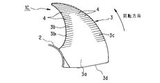
図2は本発明の第1の実施形態に係る軸流送風機1の全体を負圧面側から見たときの正面図、図1はこの軸流送風機1の一部を省略した負圧面側の一部拡大正面図、図3はこの軸流送風機1の翼面上を流れる空気の流れ方向を示す横式図である。これらの図において、軸流送風機1は、図示しない駆動モータの回転軸が同心状に固定される円筒状のボス部2の外側周面に、複数枚の翼3,3,3を周方向等分位置にて一体ないし一体的に取り付けている。
【0035】
そして、図1、図3にも示すように軸流送風機1は各翼3の負圧面3a側の前縁部3bと、外周部3cとに、図3中、太線矢印で示す空気流れに交差する方向に延びる細溝からなる複数のリブレット4をそれぞれ形成している。ここで空気流れに交差する方向とは直交と斜交とを含む。
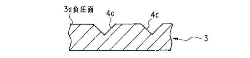
【0036】
図4に示すように各リブレット4は、各翼3の負圧面3a側に開口する断面形状が矩形の細溝よりなり、各翼3の所要強度が得られつつ空気流れ剥離抑制効果が最大限に発揮されるようにリブレット幅(溝幅)wと、リブレット深さ(溝深さ)dが、各翼3の翼厚tと、最大翼弦長Cに対し、次の(1)式を満たすように形成されている。
【0037】
【数1】

さらに、各リブレット4はこの(1)式の条件に加えて隣り合うリブレット4どうし間の間隔sとリブレット幅wとの比がs/w≦3を成立するように形成されている。
【0039】
したがって、軸流送風機1の回転時には、図3中太線矢印で示すように空気流れは各翼3の前縁部3a側から後縁3d側へ流れる流れと、外周部3c側から後縁3d側へ流れる流れとがあるが、これら空気流れは前縁部3aと外周部3cの複数のリブレット4により翼面境界層は層流から乱流への遷移が促進される。この乱流境界層は層流境界層よりも空気流れの剥離がしにくいので、送風性能の向上と、送風騒音の低減効果が得られる。
【0040】
しかも、各リブレット4は空気流れに交差する方向に形成されているので、軸流送風機1の回転動作時の負荷や単位時間当りの回転数(以下、単に回転数という)等の使用条件によって翼面流れの方向が変化する場合においても、その流れの変化に対する自由度を得ることができ、この場合にも空気流れの剥離を抑制することができる。
【0041】
さらに、溝からなるリブレット4を複数形成する範囲を、流れの剥離抑制に有効な各翼3の前縁部3bと外周部3cとに限定しているので、流れの剥離抑制効果と各翼3の強度の確保を両立させることができる。
【0042】
図5はこのように構成された軸流送風機1を、室外ファンとして組み込む空気調和機用室外機5の一部切欠斜視図、図6はこの室外機5の概略平断面図である。この室外機5は角筒状の室外ユニット6内に、例えば平面L形状の室外熱交換器7、コンプレッサ8、四方弁9、インバータ等の制御器10等を収容し、室外ファン(軸流送風機)1とコンプレッサ8との間を仕切板11により仕切っている。なお、符号12はベルマウス、13は吹出口に装着される吹出ガードである。このように構成された室外機5は軸流送風機1の回転により、図6中小矢印に示すように室外熱交換器7の背面側から外部空気を吸い込み、この室外熱交換器7を通風させてから正面のベルマウス19側から再び外部へ吹き出すことにより、室外熱交換器7の外面に空気を通風させ、この室外熱交換器7内を通液する冷媒を外気と熱交換を促進させている。
【0043】
図7はこのようにこの軸流送風機1を室外ファンとして組み込んだ室外機5の送風騒音をA曲線で示し、リブレット4のない従来の室外ファンを組み込んだ室外機の送風騒音を示すB曲線と比較して示している。また、この図7は、A曲線で示す本実施形態に係る軸流送風機1の送風騒音の方がB曲線で示す従来例よりもファン回転数[rpm]のほぼ全域において約1dBA程度低減していることを示している。
【0044】
また、図4に示すように各リブレット4は、その断面形状、幅w、深さd、隣り合うリブレット4どうしの間隔sを、流れ剥離抑制効果が最大限に発揮される点と、各翼3の所要強度が得られる点とが両立するように設定されているので、各翼3の強度を確保しつつ流れ剥離抑制効果を最大限奏することができる。
【0045】
図8(A)は各翼3に形成した各リブレット4の送風機半径方向外周側の溝側壁を翼負圧面3a側に向けて拡開するテーパ壁4aに形成した点を示す断面図である。
【0046】
すなわち、各翼3は、ボス部2の外側周面に、このボス部2に同心状に固定される回転軸2aの直角方向、つまり、図8(A)中、水平方向に対し右肩上りの所要角度で傾斜して取り付けられているために、仮に、各リブレット4にテーパ壁4aを形成しない場合には、図8(B)に示すように各リブレット4aの送風機半径方向外周側の溝側壁4bの下部が回転軸2aの平行線よりも送風機半径方向外方側へ突出するアンダーカット部4bが形成されてしまう。この場合に、この軸流送風機1を射出成型すると、その金型からの成形加工の抜きがアンダーカット部4bにより困難になるために、その金型構造が複雑になり、コストアップを招くうえに、その成形作業の作業性が低下するという課題が発生する。
【0047】
そこで、本実施形態は上述したように図8(A)に示すように各リブレット4の送風機半径方向外周側の各溝側壁をテーパ壁4aに形成することにより、金型構造を簡単化することができるうえに、金型からの成形品を容易に抜くことができる。
【0048】
図9は本発明の第2の実施形態に係る軸流送風機1Aの要部拡大正面図である。この軸流送風機1Aは、複数のリブレット4を形成する各翼3の負圧面3a側前縁部3bと外周部3cの設置領域をそれぞれ明確に規定した点に特徴がある。
【0049】
すなわち、リブレット4を形成する前縁部3bを、その前縁端3b1 から、その法線方向かつ翼面内方へ所定距離L離れた点において、この前縁端3b1 にほぼ平行に伸びる曲線Pと、この前縁端3b1 とで囲まれた領域に規定している。
【0050】
また、リブレット4を形成する外周部3cを、その外周端3c1 から、その法線方向かつ翼面内方へ所定距離M離れた点において、この外周端3c1 にほぼ平行に伸びる曲線Qと、この外周端3c1 とで囲まれた領域に規定している。
【0051】
そして、これら所定距離L,Mを各翼3の最大翼弦長Cに対し、それぞれ次の(2)式を満たすように設定している。
【0052】
【数2】
図10は本発明の第3実施形態に係る軸流送風機1Bの要部拡大正面図である。この軸流送風機1Bは、リブレット4を形成する前縁部3bを、前縁端3b1 から法線方向内方へ所定距離Lb離れた点において、前縁端3b1 にほぼ平行に伸びる曲線Pbと、同じく前縁端3b1 から所定距離La(La>Lb)離れた点において、前縁端3b1 にほぼ平行に延びる曲線Paとにより囲まれた領域に限定している。
【0054】
また、リブレット4を形成する外周部3cを、外周端3c1 から法線方向内方へ所定距離Mc離れた点において、外周端3c1 にほぼ平行に伸びる曲線Qcと、同じく外周端3c1 から所定距離Ma(Ma>Mb)離れた点において、外周端3c1 にほぼ平行に延びる曲線Qaとにより囲まれた領域に限定している。
【0055】
そして、これら所定距離Ma,Mb,La,Lbを各翼3の最大翼弦長Cに対し、それぞれ次の(3)式を満たすように設定している。
【0056】
【数3】
図11は本発明の第4実施形態に係る軸流送風機1Cの要部拡大正面図である。この軸流送風機1Cは各翼3の前縁部3bと外周部3cの各一部にリブレット4を形成し、前縁部3bのボス部2の近傍と、外周部3cの後縁3d側とにはリブレット4を形成しない点に特徴がある。
【0058】
この軸流送風機1Cによっても空気流れ剥離抑制効果が得られるうえに、リブレット4の形成を省略したボス部2近傍の前縁部3bと、外周部3cの後縁3d近傍の部分は他に比して比較的薄肉であるので、この部分のリブレット4を省略することにより、この部分の翼強度の向上を図ることができる。
【0059】
なお、リブレット4の断面形状は図4で示す矩形に限定されるものではなく、例えば図12に示すように三角形4cでもよく、さらに図13で示す円弧状4dでもよい。
【0060】
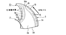
図14は本発明の第5実施形態に係る軸流送風機1Dの要部拡大正面図である。この軸流送風機1Dは各翼3の前縁部3bと外周部3cとにそれぞれ形成されるリブレット4を破線状溝13により形成した点に特徴がある。
【0061】
破線状溝13は図15に示すように例えば図中横長矩形状で所定大の溝14aを形成する溝形成部14と、この溝14aを形成しない非形成部15とを長手方向(図15では横方向)に交互に配置して溝14aが長手方向で連続しないようになっている。図14に示すように、この破線状溝13の複数個は各翼3の負圧面3a側の前縁部3bと外周部3cとにそれぞれ形成され、その長手方向が空気流れと交差するように配列されている。
【0062】
そして、図15に示すように図中縦方向で隣り合う破線状溝13同士は、溝形成部14と非形成部15の配列が図15中縦方向で一致しないように位相を反転させており、溝形成部14の溝14aが千鳥状に配設されるようになっている。このために、破線状溝13が形成される前縁部3bと外周部3cの強度を、溝が長手方向で連続する連続溝をリブレット4として形成する場合よりも増強させることができる。
【0063】
図16は各破線状溝13の溝14aの断面を示しており、各溝14aは、各翼3の負圧面3a側に開口する矩形断面に形成されており、各溝14aの溝幅w、溝深さdは各翼3の最大翼弦長C、翼厚tに対し、次の(4)式が満たされるようになっている。
【0064】
【数4】
また、図17の要部拡大正面図に示すように各溝14aの溝長さxaと非形成部15の長さxbとを略同一長さとするとともに、各溝14aの溝長さxaと溝幅wの比を、概ね5:1に設定している。
【0066】
さらに、図18の要部拡大正面図に示すように、各溝14aの各コーナ部を円弧状に形成している。また、図19に示すように、各破線状溝13の溝14aの送風機半径方向外周側壁を、負圧面3a側に拡開するテーパ壁14bに形成している。その理由は図4で示すリブレット4にアンダーカット部が生じないように構成した点と同様であり、これにより、軸流送風機1Dを射出成形する場合に使用される金型構造の簡単化を図ることができる。
【0067】
そして、このように構成された軸流送風機1Dによれば、各翼3の多数の破線状溝13により、空気の翼面境界層は層流から乱流への遷移が促進される。層流境界層よりも乱流境界層の方が流れは剥離しにくいため、送風性能の向上と、送風騒音低減効果が得られる。但し、溝を乱流境界層に遷移した領域に設置すると、逆に流れの剥離を招く等の現象が生じる。また従来形状のリブレットにおいては、連続した溝が各翼に形成されるため、特に薄肉翼に適用した場合は強度が低下し、高速回転時の遠心力や、衝撃等の外力が付加された場合に、溝に沿って破壊が起こり易い。これに対し、本実施形態は破線状溝31を、比較的厚肉部分である翼の前縁部3bと外周部3cとに形成するので、流れの剥離を効果的に抑制することができる。また、破線状溝13は長手方向に不連続な破線状の溝14aにより形成されるため、溝14aによる強度低下は最小限に抑えることができる。
【0068】
図20は本発明の第6の実施形態に係る軸流送風機1Eの要部拡大正面図である。この軸流送風機1Eは、複数の破線状溝13を形成する各翼3の負圧面3a側前縁部3bと外周部3cの領域をそれぞれ明確に規定した点に特徴がある。
【0069】
すなわち、破線状溝13を形成する前縁部3bを、その前縁端3b1 から、その法線方向かつ翼面内方へ所定距離Lc離れた点において、この前縁端3b1 にほぼ平行に伸びる曲線Pcと、この前縁端3b1 とで囲まれた領域に規定している。
【0070】
また、破線状溝13を形成する外周部3cを、その外周端3c1 から、その法線方向かつ翼面内方へ所定距離Mc離れた点において、この外周端3c1 にほぼ平行に伸びる曲線Qcと、この外周端3c1 とで囲まれた領域に規定している。
【0071】
そして、これら所定距離Lc,Mcを各翼3の最大翼弦長Cに対し、それぞれ次の(5)式を満たすように設定している。
【0072】
【数5】
図21は本発明の第3実施形態に係る軸流送風機1Fの要部拡大正面図である。この軸流送風機1Fは、破線状溝13を形成する前縁部3bを、前縁端3b1 から法線方向内方へ所定距離Ld離れた点において、前縁端3b1 にほぼ平行に伸びる曲線Pdと、同じく前縁端3b1 から所定距離Lc(Lc>Ld)離れた点において、前縁端3b1 にほぼ平行に延びる曲線Pcとにより囲まれた領域に限定している。
【0074】
また、破線状溝13を形成する外周部3cを、外周端3c1 から法線方向内方へ所定距離Md離れた点において、外周端3c1 にほぼ平行に伸びる曲線Qdと、同じく外周端3c1 から所定距離Mc(Mc>Md)離れた点において、外周端3c1 にほぼ平行に延びる曲線Qcとにより囲まれた領域に限定している。
【0075】
そして、これら所定距離Mc,Md,Lc,Ldを各翼3の最大翼弦長Cに対し、それぞれ次の(3)式を満たすように設定している。
【0076】
【数6】
図22は本発明の第8実施形態に係る軸流送風機1Gの要部拡大正面図である。この軸流送風機1Gは各翼3の前縁部3bと外周部3cの各一部に破線状溝13を形成し、前縁部3bのボス部2の近傍と、外周部3cの後縁3d側とには破線状溝13を形成しない点に特徴がある。
【0078】
この軸油送風機1Gによっても空気流れ剥離抑制効果が得られるうえに、破線状溝13の形成を省略したボス部2近傍の前縁部3bと、外周部3cの後縁3d近傍の部分は他に比して比較的薄肉であるので、この部分の破線状溝13の形成を省略することにより、この部分の翼強度の向上を図ることができる。
【0079】
図23は本発明の第7実施形態に係る軸流送風機1Hの要部拡大正面図である。この軸流送風機1Hは、各翼3の回転方向に沿う周方向のほぼ中間部よりも前縁3b1 側の前縁部3bと外周部3cと、これら両者間の翼面3eとに、複数の破線状溝13を図23中横方向に連続して形成した点に特徴がある。これら破線状溝13の形成領域は、これ以外の領域よりも翼肉厚が比較的厚肉に形成されているので、各翼3の所要強度を確保することができると共に、空気流れの剥離を抑制する効果を有する。
【0080】
なお、各破線状溝13の各溝14aの断面形状は図16で示す矩形に限定されるものではなく、例えば三角形でもよく、さらに円弧状でもよい。
【0081】
【発明の効果】
以上説明したように本発明によれば、各翼の前縁部と外周部にのみ形成した複数の溝により、各翼の翼面流れの層流から乱流への遷移が促進されることにより、空気流れの剥離が抑制される。しかも、各溝は、空気流れに交差する方向に形成されているので、空気流れの方向の変化に対する自由度を得ることができるとともに、溝の設置範囲を、流れ剥離抑制に有効な各翼の前縁部と外周部に設定しているので、流れの剥離抑制効果と各翼の強度確保を共に図ることができる。
【0082】
さらに、乱流境界層に遷移した領域に溝を設けると、逆に流れの剥離を招くが、本発明はこの溝を形成する領域を各翼の前縁部と外周部とに限定することにより、乱流境界層に遷移した領域には溝を設けないので、流れの剥離抑制効果を一段と向上させることができる。これにより、送風性能の向上と送風騒音の低減を共に図ることができる。また、溝がその長手方向で連続しない破線状溝である場合には、溝が連続する場合に比して翼強度の向上を図ることができる。
【図面の簡単な説明】
【図1】本発明の第1の実施形態に係る軸流送風機の負圧面側の要部拡大正面図。
【図2】図1で示す軸流送風機の全体構成を示す負圧面側の正面図。
【図3】図1で示す軸流送風機の回転時の空気の流れ方向を示す模式図。
【図4】図1で示す軸流送風機のリブレット周辺部の部分縦断面図。
【図5】図1で示す軸流送風機を室外ファンとして組み付けた空気調和機用室外機の一部切欠斜視図。
【図6】図5の概略平断面図。
【図7】図5等で示す室外機の送風騒音の低減効果を示すグラフ。
【図8】(A)は図1等で示す軸流送風機の各リブレットにテーパ壁を設けた場合の要部縦断面図、(B)はリブレットにテーパ壁を設けないときに、リブレットにアンダーカット部が形成される状態を示す要部縦断面図。
【図9】本発明の第2の実施形態に係る軸流送風機の負圧面側の要部拡大正面図。
【図10】本発明の第3の実施形態に係る軸流送風機の負圧面側の要部拡大正面図。
【図11】本発明の第4の実施形態に係る軸流送風機の負圧面側の要部拡大正面図。
【図12】本発明の各実施形態に形成されるリブレットの断面形状を三角形に形成した場合の縦断面図。
【図13】本発明の各実施形態に形成されるリブレットの断面形状を円弧形に形成した場合の縦断面図。
【図14】本発明の第5の実施形態に係る軸流送風機の負圧面側の要部拡大正面図。
【図15】図14で示す複数の破線状溝周辺部の一部拡大正面図。
【図16】図14で示す複数の破線状溝周辺部の要部縦断面図。
【図17】図14で示す複数の破線状溝周辺部の一部拡大正面図。
【図18】図14で示す複数の破線状溝周辺部の変形例の一部拡大正面図。
【図19】図14で示す実施形態の要部拡大縦断面図。
【図20】本発明の第6の実施形態に係る軸流送風機の負圧面側の要部拡大正面図。
【図21】本発明の第7の実施形態に係る軸流送風機の負圧面側の要部拡大正面図。
【図22】本発明の第8の実施形態に係る軸流送風機の負圧面側の要部拡大正面図。
【図23】本発明の第9の実施形態に係る軸流送風機の負圧面側の要部拡大正面図。
【符号の説明】
1,1A,1B,1C,1D,1E,1F,1G,1H 軸流送風機
2 ボス部
2a 回転軸
3 翼
3a 翼の負圧面
3b 前縁部
3c 外周部
3d 後縁
3e 翼面
4 リブレット(溝)
4a リブレットのテーパ壁
4b リブレットのアンダーカット部
5 空気調和機用室外機
13 破線状溝
14 溝形成部
14a 溝
14b 溝のテーパ壁
15 非形成部[0001]
BACKGROUND OF THE INVENTION
The present invention relates to an axial blower suitable for an outdoor fan of an outdoor unit for an air conditioner, and more particularly to an axial blower that prevents or reduces air flow separation.
[0002]
[Prior art]
In general, in an outdoor unit or the like of an air conditioner, an axial blower such as a propeller fan is frequently used as an outdoor fan. A conventional axial blower of this type is described in Japanese Utility Model Publication No. 63-98499.
[0003]
In this axial fan, a plurality of riblets are formed on a plurality of concentric circles around the rotation axis on at least one of the positive and negative pressure surfaces of a plurality of blades arranged around the boss portion. Air flow separation is reduced.
[0004]
[Problems to be solved by the invention]
However, in such a conventional axial blower, each riblet is formed along the air flow direction. Therefore, depending on the usage conditions such as the load and the rotational speed during the rotational operation of this axial blower, the blade surface flow In this case, the effect of reducing the air flow separation is hardly exhibited, and conversely, the air blowing performance may be adversely affected.
[0005]
In addition, riblets are effective in promoting turbulent flow in the laminar boundary region, but transition to the turbulent boundary layer is achieved by forming riblets on almost the entire surface of each blade as in this conventional axial fan. In the case where riblets are formed also in the region, there are problems such as conversely causing separation of the air flow.
[0006]
The present invention has been made in consideration of such circumstances, and its purpose is to effectively suppress separation of air flow, and to achieve both axial performance that can improve air blowing performance and reduce air blowing noise. It is to provide a blower.
[0007]
[Means for Solving the Problems]
The invention according to
[0008]
According to the present invention, the transition from laminar flow to turbulent flow of the blade surface flow of each blade is promoted by the plurality of grooves formed only at the front edge portion and the outer peripheral portion of each blade. Peeling is suppressed. Moreover, since each groove is formed in a direction intersecting the air flow, it is possible to obtain a degree of freedom with respect to a change in the direction of the air flow, and the groove installation range is effective for suppressing flow separation, and Since the front edge portion and the outer peripheral portion are set to be relatively thick, it is possible to achieve both the effect of suppressing flow separation and ensuring the strength of each blade.
[0009]
Furthermore, if a groove is provided in the region transitioning to the turbulent boundary layer, flow separation is caused conversely, but the present invention limits the region where this groove is formed to the front edge and the outer periphery of each blade. Since no groove is provided in the region transitioned to the turbulent boundary layer, the flow separation inhibiting effect can be further improved. Thereby, improvement of ventilation performance and reduction of ventilation noise can be aimed at together.
[0012]
In addition, since the shape and dimensions of each groove are set to the optimum shape and dimensions that maximize the air flow separation suppression effect, the air flow separation suppression effect can be achieved without reducing the strength of each blade. It can be used to the fullest.
[0033]
DETAILED DESCRIPTION OF THE INVENTION
Hereinafter, embodiments of the present invention will be described with reference to FIGS. In these drawings, the same or responsible portions are denoted by the same reference numerals.
[0034]
FIG. 2 is a front view of the entire
[0035]
As shown in FIGS. 1 and 3, the
[0036]
As shown in FIG. 4, each
[0037]
[Expression 1]
Further, each
[0039]
Therefore, when the
[0040]
In addition, since each
[0041]
Furthermore, since the range in which a plurality of
[0042]
FIG. 5 is a partially cutaway perspective view of the outdoor unit 5 for an air conditioner incorporating the
[0043]
FIG. 7 shows, in curve A, the blowing noise of the outdoor unit 5 in which the
[0044]
Further, as shown in FIG. 4, each
[0045]
FIG. 8A is a cross-sectional view showing a point where a groove side wall on the outer peripheral side in the blower radial direction of each
[0046]
That is, each
[0047]
Therefore, as described above, the present embodiment simplifies the mold structure by forming the groove sidewalls on the outer peripheral side of the blower radial direction of each
[0048]
FIG. 9 is an enlarged front view of a main part of an axial blower 1A according to the second embodiment of the present invention. This axial blower 1A is characterized in that it clearly defines the installation areas of the
[0049]
That is, the curve P extending from the front edge 3b1 to the front edge 3b1 substantially parallel to the front edge 3b1 at a predetermined distance L from the front edge 3b1 in the normal direction and inward of the blade surface. And a region surrounded by the front edge 3b1.
[0050]
Further, the outer
[0051]
The predetermined distances L and M are set so as to satisfy the following equation (2) with respect to the maximum chord length C of each
[0052]
[Expression 2]
FIG. 10 is an enlarged front view of a main part of an axial blower 1B according to the third embodiment of the present invention. The axial blower 1B includes a curve Pb extending substantially parallel to the front edge 3b1 at a point where the
[0054]
Further, the outer
[0055]
The predetermined distances Ma, Mb, La, and Lb are set so as to satisfy the following expression (3) with respect to the maximum chord length C of each
[0056]
[Equation 3]
FIG. 11 is an enlarged front view of a main part of an axial blower 1C according to the fourth embodiment of the present invention. This axial blower 1C is formed with
[0058]
This axial flow blower 1C also provides the effect of suppressing air flow separation, and the
[0059]
In addition, the cross-sectional shape of the
[0060]
FIG. 14 is an enlarged front view of a main part of an axial blower 1D according to the fifth embodiment of the present invention. This axial-flow fan 1D is characterized in that
[0061]
As shown in FIG. 15, the broken line-shaped
[0062]
As shown in FIG. 15, the broken-
[0063]
FIG. 16 shows a cross section of the
[0064]
[Expression 4]
Further, as shown in the enlarged front view of the main part of FIG. 17, the groove length xa of each
[0066]
Further, as shown in the enlarged front view of the main part of FIG. 18, each corner portion of each
[0067]
According to the axial blower 1D configured in this way, the transition from laminar flow to turbulent flow is promoted in the blade blade boundary layer by the numerous broken-
[0068]
FIG. 20 is an enlarged front view of a main part of an
[0069]
That is, the
[0070]
Further, the outer
[0071]
The predetermined distances Lc and Mc are set so as to satisfy the following expression (5) with respect to the maximum chord length C of each
[0072]
[Equation 5]
FIG. 21 is an enlarged front view of a main part of an axial blower 1F according to the third embodiment of the present invention. This axial blower 1F has a curved line Pd extending substantially parallel to the front edge 3b1 at a point a predetermined distance Ld away from the front edge 3b1 in the normal direction from the front edge 3b1 of the
[0074]
Further, the outer
[0075]
The predetermined distances Mc, Md, Lc, and Ld are set so as to satisfy the following expression (3) with respect to the maximum chord length C of each
[0076]
[Formula 6]
FIG. 22 is an enlarged front view of a main part of an
[0078]
The
[0079]
FIG. 23 is an enlarged front view of a main part of an axial blower 1H according to the seventh embodiment of the present invention. The axial blower 1H has a plurality of
[0080]
In addition, the cross-sectional shape of each groove |
[0081]
【The invention's effect】
As described above, according to the present invention, the transition from laminar flow to turbulent flow of the blade surface flow of each blade is promoted by the plurality of grooves formed only at the leading edge and the outer peripheral portion of each blade. Air flow separation is suppressed. Moreover, since each groove is formed in a direction crossing the air flow, it is possible to obtain a degree of freedom with respect to changes in the direction of the air flow, and to set the groove installation range of each blade effective in suppressing flow separation. Since the front edge portion and the outer peripheral portion are set, it is possible to achieve both the effect of suppressing flow separation and ensuring the strength of each blade.
[0082]
Furthermore, if a groove is provided in the region transitioning to the turbulent boundary layer, flow separation is caused conversely, but the present invention limits the region where this groove is formed to the front edge and the outer periphery of each blade. Since no groove is provided in the region transitioned to the turbulent boundary layer, the flow separation inhibiting effect can be further improved. Thereby, improvement of ventilation performance and reduction of ventilation noise can be aimed at together. Further, when the groove is a broken-line groove that is not continuous in the longitudinal direction, the blade strength can be improved as compared with the case where the groove is continuous.
[Brief description of the drawings]
FIG. 1 is an enlarged front view of a main part of a suction surface side of an axial blower according to a first embodiment of the present invention.
2 is a front view of the suction surface side showing the overall configuration of the axial blower shown in FIG. 1. FIG.
FIG. 3 is a schematic diagram showing the direction of air flow when the axial blower shown in FIG. 1 rotates.
4 is a partial longitudinal sectional view of a peripheral portion of a riblet of the axial blower shown in FIG.
FIG. 5 is a partially cutaway perspective view of an outdoor unit for an air conditioner in which the axial fan shown in FIG. 1 is assembled as an outdoor fan.
6 is a schematic cross-sectional view of FIG.
FIG. 7 is a graph showing the effect of reducing the blowing noise of the outdoor unit shown in FIG.
8A is a longitudinal sectional view of a main part when a taper wall is provided on each riblet of the axial blower shown in FIG. 1 and the like, and FIG. 8B is an underlined riblet when the riblet is not provided with a taper wall. The principal part longitudinal cross-sectional view which shows the state in which a cut part is formed.
FIG. 9 is an enlarged front view of a main part of a suction surface side of an axial blower according to a second embodiment of the present invention.
FIG. 10 is an enlarged front view of a main part on the suction surface side of an axial blower according to a third embodiment of the present invention.
FIG. 11 is an enlarged front view of a main part on the suction surface side of an axial blower according to a fourth embodiment of the present invention.
FIG. 12 is a longitudinal sectional view when the riblet formed in each embodiment of the present invention has a triangular cross-sectional shape.
FIG. 13 is a longitudinal sectional view when the cross-sectional shape of the riblet formed in each embodiment of the present invention is formed in an arc shape.
FIG. 14 is an enlarged front view of a main part on the suction surface side of an axial blower according to a fifth embodiment of the present invention.
15 is a partially enlarged front view of the periphery of a plurality of broken-line grooves shown in FIG.
16 is a longitudinal sectional view of an essential part of the periphery of a plurality of broken-line grooves shown in FIG.
17 is a partially enlarged front view of the periphery of a plurality of broken-line grooves shown in FIG.
18 is a partially enlarged front view of a modified example of the periphery of a plurality of broken-line grooves shown in FIG.
FIG. 19 is an enlarged vertical sectional view of a main part of the embodiment shown in FIG.
FIG. 20 is an enlarged front view of a main part on the suction surface side of an axial blower according to a sixth embodiment of the present invention.
FIG. 21 is an enlarged front view of a main part on the suction surface side of an axial blower according to a seventh embodiment of the present invention.
FIG. 22 is an enlarged front view of a main part on the suction surface side of an axial blower according to an eighth embodiment of the present invention.
FIG. 23 is an enlarged front view of a main part on the suction surface side of an axial blower according to a ninth embodiment of the present invention.
[Explanation of symbols]
1, 1A, 1B, 1C, 1D, 1E, 1F, 1G, 1H
4a
Claims (3)
各溝は、その溝幅を、各翼の最大翼弦長の0.2〜1.0%に設定する一方、その溝深さを、この溝幅の20%以上で且つ、翼厚みの50%以下に設定していることを特徴とする軸流送風機。In the axial blower which is disposed a plurality of blades around the boss portion, a plurality intersecting said leading edge portion and the outer peripheral portion of the negative pressure surface of each blade only, respectively along the front edge portion and the outer peripheral portion and the direction of air flow groove is formed of,
Each groove has its groove width set to 0.2 to 1.0% of the maximum chord length of each blade, while its groove depth is 20% or more of this groove width and 50 blade thickness. An axial blower characterized by being set to not more than% .
Priority Applications (1)
| Application Number | Priority Date | Filing Date | Title |
|---|---|---|---|
| JP28167298A JP4153601B2 (en) | 1998-10-02 | 1998-10-02 | Axial blower |
Applications Claiming Priority (1)
| Application Number | Priority Date | Filing Date | Title |
|---|---|---|---|
| JP28167298A JP4153601B2 (en) | 1998-10-02 | 1998-10-02 | Axial blower |
Publications (3)
| Publication Number | Publication Date |
|---|---|
| JP2000110790A JP2000110790A (en) | 2000-04-18 |
| JP2000110790A5 JP2000110790A5 (en) | 2005-08-18 |
| JP4153601B2 true JP4153601B2 (en) | 2008-09-24 |
Family
ID=17642380
Family Applications (1)
| Application Number | Title | Priority Date | Filing Date |
|---|---|---|---|
| JP28167298A Expired - Fee Related JP4153601B2 (en) | 1998-10-02 | 1998-10-02 | Axial blower |
Country Status (1)
| Country | Link |
|---|---|
| JP (1) | JP4153601B2 (en) |
Cited By (1)
| Publication number | Priority date | Publication date | Assignee | Title |
|---|---|---|---|---|
| US11118599B2 (en) | 2015-08-10 | 2021-09-14 | Mitsubishi Electric Corporation | Fan and air-conditioning apparatus equipped with fan |
Families Citing this family (4)
| Publication number | Priority date | Publication date | Assignee | Title |
|---|---|---|---|---|
| TW524928B (en) * | 2001-04-26 | 2003-03-21 | Daikin Ind Ltd | Blower and air conditioner with the same |
| CN204878059U (en) * | 2014-12-17 | 2015-12-16 | 依必安-派特穆尔芬根股份有限两合公司 | Blade and fan wheel |
| WO2019021468A1 (en) * | 2017-07-28 | 2019-01-31 | 三菱電機株式会社 | Propeller fan and refrigeration cycle device |
| DE102022213765A1 (en) * | 2022-12-16 | 2024-06-27 | Ziehl-Abegg Se | Turbomachine and method for producing a component of a turbomachine that carries a flow medium |
-
1998
- 1998-10-02 JP JP28167298A patent/JP4153601B2/en not_active Expired - Fee Related
Cited By (1)
| Publication number | Priority date | Publication date | Assignee | Title |
|---|---|---|---|---|
| US11118599B2 (en) | 2015-08-10 | 2021-09-14 | Mitsubishi Electric Corporation | Fan and air-conditioning apparatus equipped with fan |
Also Published As
| Publication number | Publication date |
|---|---|
| JP2000110790A (en) | 2000-04-18 |
Similar Documents
| Publication | Publication Date | Title |
|---|---|---|
| JP3843941B2 (en) | Centrifugal blower | |
| AU2003207098B2 (en) | Fan | |
| JP4388992B1 (en) | Propeller fan, fluid feeder and mold | |
| JP4035237B2 (en) | Axial blower | |
| US8721280B2 (en) | Propeller fan | |
| JP4185654B2 (en) | Centrifugal multi-blade blower | |
| EP2381113B1 (en) | Propeller fan, fluid feeder and molding die | |
| JP2010133254A (en) | Centrifugal blower, and air conditioner provided with the same | |
| JP2012026402A (en) | Mixed flow fan and air conditioner with the same | |
| JP3812537B2 (en) | Centrifugal blower | |
| JP2003232295A (en) | Centrifugal fan and cooker equipped with the centrifugal fan | |
| JP2006322378A (en) | Blower impeller | |
| JP4153601B2 (en) | Axial blower | |
| EP1298326A1 (en) | Propeller fan, propeller fan molding mold, and fluid feeding device | |
| JP3649157B2 (en) | Centrifugal fan and air conditioner equipped with the centrifugal fan | |
| JP2003184792A (en) | Blower | |
| JP4483148B2 (en) | Impeller for axial fan | |
| JPH10306796A (en) | Centrifugal sirocco fan | |
| JP4388993B1 (en) | Propeller fan, fluid feeder and mold | |
| KR100663965B1 (en) | Axial flow fan | |
| JP3882324B2 (en) | Centrifugal fan | |
| JP2010106853A (en) | Cross-flow fan, blower, and impeller forming machine | |
| JP2001159396A (en) | Centrifugal fan and air conditioner equipped with the same | |
| JP2000265997A (en) | Vane type propeller fan | |
| JP2010106854A (en) | Cross-flow fan, blower, and impeller forming machine |
Legal Events
| Date | Code | Title | Description |
|---|---|---|---|
| A521 | Written amendment |
Free format text: JAPANESE INTERMEDIATE CODE: A523 Effective date: 20050201 |
|
| A621 | Written request for application examination |
Free format text: JAPANESE INTERMEDIATE CODE: A621 Effective date: 20050201 |
|
| A977 | Report on retrieval |
Free format text: JAPANESE INTERMEDIATE CODE: A971007 Effective date: 20080303 |
|
| A131 | Notification of reasons for refusal |
Free format text: JAPANESE INTERMEDIATE CODE: A131 Effective date: 20080311 |
|
| A521 | Written amendment |
Free format text: JAPANESE INTERMEDIATE CODE: A523 Effective date: 20080512 |
|
| A711 | Notification of change in applicant |
Free format text: JAPANESE INTERMEDIATE CODE: A712 Effective date: 20080521 |
|
| TRDD | Decision of grant or rejection written | ||
| A01 | Written decision to grant a patent or to grant a registration (utility model) |
Free format text: JAPANESE INTERMEDIATE CODE: A01 Effective date: 20080701 |
|
| A01 | Written decision to grant a patent or to grant a registration (utility model) |
Free format text: JAPANESE INTERMEDIATE CODE: A01 |
|
| A61 | First payment of annual fees (during grant procedure) |
Free format text: JAPANESE INTERMEDIATE CODE: A61 Effective date: 20080704 |
|
| R150 | Certificate of patent or registration of utility model |
Free format text: JAPANESE INTERMEDIATE CODE: R150 |
|
| FPAY | Renewal fee payment (event date is renewal date of database) |
Free format text: PAYMENT UNTIL: 20110711 Year of fee payment: 3 |
|
| FPAY | Renewal fee payment (event date is renewal date of database) |
Free format text: PAYMENT UNTIL: 20110711 Year of fee payment: 3 |
|
| FPAY | Renewal fee payment (event date is renewal date of database) |
Free format text: PAYMENT UNTIL: 20120711 Year of fee payment: 4 |
|
| FPAY | Renewal fee payment (event date is renewal date of database) |
Free format text: PAYMENT UNTIL: 20120711 Year of fee payment: 4 |
|
| FPAY | Renewal fee payment (event date is renewal date of database) |
Free format text: PAYMENT UNTIL: 20130711 Year of fee payment: 5 |
|
| LAPS | Cancellation because of no payment of annual fees |