JP4151990B2 - Adapting method for channel assignment in cellular communication systems - Google Patents
Adapting method for channel assignment in cellular communication systems Download PDFInfo
- Publication number
- JP4151990B2 JP4151990B2 JP51856798A JP51856798A JP4151990B2 JP 4151990 B2 JP4151990 B2 JP 4151990B2 JP 51856798 A JP51856798 A JP 51856798A JP 51856798 A JP51856798 A JP 51856798A JP 4151990 B2 JP4151990 B2 JP 4151990B2
- Authority
- JP
- Japan
- Prior art keywords
- station
- subscriber station
- signal
- cell
- power level
- Prior art date
- Legal status (The legal status is an assumption and is not a legal conclusion. Google has not performed a legal analysis and makes no representation as to the accuracy of the status listed.)
- Expired - Lifetime
Links
Images


Classifications
-
- H—ELECTRICITY
- H04—ELECTRIC COMMUNICATION TECHNIQUE
- H04W—WIRELESS COMMUNICATION NETWORKS
- H04W52/00—Power management, e.g. TPC [Transmission Power Control], power saving or power classes
- H04W52/04—TPC
- H04W52/38—TPC being performed in particular situations
- H04W52/50—TPC being performed in particular situations at the moment of starting communication in a multiple access environment
-
- H—ELECTRICITY
- H04—ELECTRIC COMMUNICATION TECHNIQUE
- H04W—WIRELESS COMMUNICATION NETWORKS
- H04W72/00—Local resource management
-
- H—ELECTRICITY
- H04—ELECTRIC COMMUNICATION TECHNIQUE
- H04W—WIRELESS COMMUNICATION NETWORKS
- H04W72/00—Local resource management
- H04W72/04—Wireless resource allocation
-
- H—ELECTRICITY
- H04—ELECTRIC COMMUNICATION TECHNIQUE
- H04W—WIRELESS COMMUNICATION NETWORKS
- H04W76/00—Connection management
- H04W76/10—Connection setup
Landscapes
- Engineering & Computer Science (AREA)
- Computer Networks & Wireless Communication (AREA)
- Signal Processing (AREA)
- Mobile Radio Communication Systems (AREA)
- Time-Division Multiplex Systems (AREA)
Abstract
Description
発明の属する技術的分野
本チャネル割当の適合方法は、無線通信システム、特にベースステーションと一式の加入者ステーションを有するセルラー、無線局部ループ、及びパーソナル通信システムにおけるトラフィックチャネルの割当に関する。
関連技術の説明
代表的なセルラー遠隔通信システムのセルは、入信電話地上回線を受け取り、そのセルがカバーするよう指定されている地域に、アンテナシステムにより同報通信される無線周波数(RF)搬送波上にその入信音声回線を多重送信するための多重送信装置が装備されているセルステーション(しばしばベースステーションと称される)の周りに構成される。個々の加入者ステーションのセットは、同報通信変調搬送波を受信し、受信を予定されているデータを搬送する特定のチャネルを多重分離するように、各々装備されている。しばしば、双方向の会話は、各トラフィックチャネル上で全二重伝送方式によってサポートされている。従って、全二重伝送方式に関する文脈内では、標識トラフィックチャネルが用いられることになる。アップリンクトラフィックチャネルは加入者ステーションからセルステーションへデータを搬送するトラフィックチャネルの部分であり、ダウンリンクトラフィックチャネルは、セルステーションから加入者ステーションへデータを搬送するトラフィックチャネルの部分である。
代表的な無線通信システムでは、割当られたRF周波数帯域幅が、様々な多重アクセス技術を用いる複数の加入者によって共有される。通常、周波数分割多重アクセス(FDMA)と時間分割多重アクセス(TDMA)技術は、複数の加入者に割当られた帯域幅を共有するのに用いられる。FDMAは、利用できる帯域幅を複数の二次帯域に細分割する。各二次帯域は、加入者データにより変調された搬送波を収容する。TDMAでは、複数の加入者の多重伝送は、1つの接続に含まれる各加入者がそのデータを伝送するための周期的なタイムスロットをパケットとして割当られる時間分割により行われる。最近では、各加入者にデジタルデータの各ビットに対して搬送波を変調するのに用いられるコード波形が割当られる単一の搬送波(又は副搬送波)上に複数の加入者を収容するために、コード分割多重アクセス(CDMA)法が導入されている。一式の直交する波形から取られた割り当てコード波形を有する各活動中の加入者は、システムを個々の加入者伝送へ分離(復調)することができる。
セルラー通信システムは、FDMA、TDMA、及び/又はCDMA法を用いるシステムで割り当てられたRF帯域幅(ロイ三世他、米国特許第5,515,378号)を増加させることなくセルステーションのアンテナ配列を使用して、加入者システムの容量を増大させることのできる、最近導入された空間分割多重アクセス(SDMA)技術の使用を含んでいてもよい。SDMAは、使用可能なシステム容量を増大させるために、加入者の空間分散を活用する。加入者はセルエリアを越えて分散される傾向にあるので、各加入者は、セルステーションアンテナ配列が加入者セルステーションアンテナ配列からどのように信号を受信し、どのように加入者セルステーションアンテナ配列へ信号を送るのかを特徴づける独自の空間サインを有するようになるであろう。その結果、各活動中の加入者の方向又は付近での効果的なアンテナ利得が最適化されるように、すなわちそれぞれの方向又は付近に対してローブの最大値が作り出されるように、そして又、送信と受信両方のために各活動中の加入者がセルステーションで分離され得るよう、各ローブは十分に狭くなるように、セルステーションは、空間サインを決定することにより、セルステーションアンテナ配列の放射パターンを制御するための電位を有する。SDNAを実行するために必要なデータ(加入者の空間サインと呼ぶ)は、各活動中の加入者からの、セルステーションで受信される送信から経験的に入手される。空間サインを使うことにより制御される制御可能なアンテナ配列パターンと組み合わせて用いられる場合、本発明の文脈においては、非空間多重送信(例えば、FDMA、TDMA、及びCDMA)は、SDMAと呼ばれることに留意されたい。(実際、空間サイン及びアンテナ配列は、空間信号処理技術を使ってセルステーションと加入者との間の通信を向上させるために、非空間分割多重アクセスシステム構成において用いることができる。これらの場合、標識SDMAは、以下の本発明の説明において、やはり用いられるであろう。)
実際のシステムは、CDMA、FDMA及びTDMA技術の中の一つ又はいくつかの組み合わせで構成することができる。例えば、FDMAとTDMA技術の組み合わせは、一式の二次帯域が更にそれぞれタイムスロットに細分割されるシステムで用いることができる。
空間サインを用いる場合、アンテナ配列を効果的な放射パターンとすれば、一つ以上の加入者に所定のパケットタイムスロットを使用させることができる。例えば、第一加入者の効果的な放射パターンの結果、パケットタイムの位置を共有する第二加入者付近で比較的低エネルギーの「零位」となり、第二加入者の空間サインが、第一加入者付近で「零位」の結果となれば、同時RFパケット伝送は二つの加入者ステーションでの受信に何ら干渉を起こさないであろう。また、二つの加入者からのセルステーションへの伝送は、セルステーションで分離することができる。これらの理想的な状態の下では、空間サインは「直交」インプリメンテーションを示すと言われている。
直交性の概念は、FDMA及びTDMAシステムにも当てはまる。何れの副搬送波内の変調データも他の何れの副搬送波を変調させるデータに影響を及ぼさないように、FDMAにおける各副搬送波が完全に分離されるなら、すべての副搬送波チャネルは互いに直交している。同様に、TDMAシステムでは、パケットデータを割り当てられた各加入者チャネルが他の活動中のチャネルに影響を及ぼさないのであれば、チャネルは互いに直交する。
直交性は、これらの多重アクセスシステムの各々で破壊される可能性がある。例えば、チャネル内で起こる干渉は、FDMAシステムでは搬送波周波数オフセットと不完全なフィルターから、TDMAシステムではクロッキングエラーと不安定性から、CDMAシステムでは同期の不正確さ又はRFマルチパスから、SDMAシステムでは有限諸元のアンテナ配列により引き起こされるアンテナパターン漏れから生じる。数百の加入者ステーションを含むであろう実際のシステムでは、システムの設計上、複雑性及びコストが必要となることもあるので、全加入者ステーション間の完全な直交性が保証されないこともある。またセルラーシステムを使用する基本的動機は、異なる位置に割り当てられるセルエリアにおける同じRFスペクトルの再利用である。この周波数再利用の原理は、慎重に制御されなければ通信の質をひどく低下させるセル間の干渉を引き起こし、最後にはシステムの容量を制限する。
直交性の脆い性質とセルラー周波数再利用によりもたらされる干渉のために、すべてのセルラー多重アクセス通信システムは、新しい加入者接続がシステムに加えられるときにチャネル間の不完全な直交性によって引き起こされる不利な影響を最小にするチャネル割当のための方法を必要としている。
また、干渉を最小にするための基本的手段は放射出力の管理なので、いずれの実用多重アクセス通信システムでも生じるあらゆる干渉を最小にするように、加入者ステーションとセルステーションの両方で用いられる放射出力を最小にすることが重要である。また、いずれの実用インプリメンテーションも、一つのセルでのRF送信は付近の他のセル内に干渉を作り出す可能性があることを認識する必要があり、近接するセルラーシステム間での完全な直交性は一般的に非現実的であり、近接するセルステーション間での直接のリアルタイム通信は不可能であろうから、セルラーシステムに更に必要なのは、一つのセルラーシステムを操作すると付近の他のセルラーシステムに生じる何らかの干渉からくる不利な影響を最小にするための方法を提供することである。セルステーション間でのセル間のリアルタイム通信は、存在しないか又は不可能かもしれないので、セルステーション間での直接のリアルタイム通信がないとしても、セルラー間の干渉の不利な影響を最小にすることは、考える必要がある。
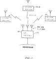
セルラー通信システムの中で加入者ステーションとセルステーションとの間に接続(図1)を確立するための現存するプロトコルの特定の例としては、1995年、12月の規格アセンブリー会議で承認された無線商工業協会(ARIB)の予備規格、第2版、RCRSTD−28に記載されている「パーソナル携帯電話システム」に用いられているものがあげられる。
ARIB予備規格、第2版に述べられているシステムは、地理的に分散された複数のパーソナル携帯電話ステーション(PSs)とセルステーション(CS)との間でRF搬送波により交信するための、所定のセル内のPSsにサービスするための、そして、標準的遠隔通信回路設備にインタフェースをとるためのデジタル無線パーソナル通信システムである。本システムは、(a)300kHzの間隔で離れている、1895−1918MHzで、パブリックシステムRF帯域を越える77のRF搬送波と、(b)各記号の周期にπ/4ラジアンの倍数の位相偏移を用いる横軸位相偏移キーイング(QPSK)変調と、(c)RF搬送波当たり4つの二重通信用TDMA−TDD(時間分割多重アクセス、時間分割二重)RFアクセスと、(d)384kbits/sの信号伝送速度と、(e)毎スロット120記号(保護ビットを含む)を有する、5msのフレーム長とを含む。
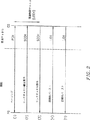
CSからPSへの着信呼び出しを設定して確立するための制御順序が図2に示されている。この着信呼び出し接続確立相は、(1)着信接続が必要な選択されたPSのページングチャネル(PCH)上でのCSのページングと、(2)リンクチャネルの確立要求を送ることにより信号制御チャネル(SCCH)上での選択されたPSの応答と、(3)トラフィックチャネル(TCH)を選択し、リンクチャネル(LCH)割当として選択されたTCHをSCCH上でPSへ送ることによる、CSのPS要求への応答と、(4)選択されたPSが、割当られたLHCへ切り換えて、一連のアイドルトラフィックバーストが後に続く一連の同期化(SYNC)バースト信号を送信することと、(5)首尾よく同期化信号を検知したら、CSが、一連のアイドルトラフィックバーストが後に続く一連のSYNCバーストをLCH上で送信し、次にCSへの着信呼び出しとの接続の確立に進み、必要とされるであろう追加のオプション信号(例えば、エンクリプションとユーザー認証)を引き出すことにより応答すること、を含む。
PCHは、CSが同一情報をページングエリア内の全PSsへ伝送する、一つのポイントから複数ポイントへ(ポイントツーマルチポイント)の一方向のダウンリンクチャネルである。SCCHは、CSと一つのPSとの間の呼び出し接続に必要な情報を送信する双方向のポイントツーポイントチャネルである。TCHは、ユーザー(加入者)情報を送信するための、ポイントツーポイントの双方向チャネルである。
上記現在の手順に関わる問題は、現在の手順が、各接続に適している送信機の出力レベルの設定に備えていないことと、現在の加入者への新しい接続から生じるであろう干渉の影響に取り組まないことである。
図3は、PSがCSとの接続の確立を要求することによって開始されるアップリンク接続を確立するための制御手順を示す。その段階は、(1)PSがリンクチャネルの確立要求を信号制御チャネル(SCCH)で送る段階と、(2)CSが、トラフィックチャネル(TCH)を選択し、リンクチャネル(LCH)割当として選択されたTCHをSCCHでPSに送ることによりPSの要求に応答する段階と、(3)PSが割当られたLCHへ切り換えて、一連のアイドルトラフィックバーストが後に続く一連の同期化(SYNC)バースト信号を伝送する段階と、(4)首尾よく同期化信号を検知したら、CSが、一連のアイドルトラフィックバーストが後に続く一連のSYNCバーストをLCH上で送信し、次にCSへの着信呼び出しとの接続の確立に進み、必要とされるであろう追加のオプション信号(例えば、エンクリプションとユーザー認証)を引き出すことにより応答する段階と、を含む。
ダウンリンク接続の確立に関する前記手順同様、アップリンク接続を確立するための手順は、同一の欠点を有しており、すなわち、適切な通信に必要な送信機出力レベルを確立する方法と、現在のユーザーに新しい接続を確立することにより作り出される干渉が与える影響を評価する方法とが欠如しているという欠点を有している。
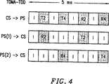
一つのPSとの接続を確立するのに用いられる制御手順は、共通のそして個々に割り当てられたタイムスロットを用いる。図4は、TDMA−TDDシステムで送信と受信に用いられるタイムスロット割当を示す。各TDD搬送波のタイム構成は、それぞれ8セグメントに分割されている5msのフレームに編成されている。各セグメントは、32kbits/s(オーバーヘッドを除く)の一方向音声チャネルをサポートする。図4は、二つのPSs(PS(1)とPS(2)、それぞれスロット2と4に割当られている)がCSと通信しているときの、共通の5msのフレームにおける活動を示す例である。通常、初めの4スロットはCSによる送信用に、従って、送信が向けられたPSの受信用に割当られる。最後の4スロットは、CS受信とPS送信に用いられる。スロット標識Iは、アイドルスロットを表す。スロット標識T(.)はそのスロットの間の送信を表し、標識R(.)は受信を表す。従って、標識(a)のフレームはCSの活動を表しており、すなわち、スロット2と4ではCSは、それぞれPS(1)とPS(2)へ送信し、スロット6と8ではCSはそれぞれPS(1)とPS(2)を聞いている。PS(1)では、スロット2は対応するCSスロット送信の受信に用いられ、スロット6はCSスロットへの送信に用いられる。同様に、フレーム(c)はPS(2)の受信及び送信活動を表す。従って、各フレームは、CSと4つのPSsとの間の最大4つの双方向通信を扱うことができる。
発明の概要
本発明は、法律により定められている使用可能な帯域幅の有効利用のために、多重送信技術を用いるセルラーシステムにおいて接続を行うための方法を指向している。本方法は、セルステーションと加入者ステーションとの間の接続を確立するための、新しいプロトコルの一部、又は現在あるプロトコルへの追加となるものである。現在あるプロトコルへの追加となる場合、本方法は、セルラーシステムで用いられている標準プロトコルと完全に互換性があり、現在のセルラーシステムのユーザー全てに完全に見えないものである。
CSと接続されている外部の通信ネットワークからの接続要求に応えて、CSからセルラーシステム内の選択されたPSへの着信呼び出し接続を確立するための方法は、(1)CSが、ダウンリンク接続が必要な、選択されたPSのページングチャネル(PCH)でページングする段階と、(2)選択されたPSが、リンクチャネル確立要求を送信することにより信号制御チャネル(SCCH)に応答する段階と、(3)CSが、トラフィックチャネル(TCH)を仮のリンクチャネル(LCH)として選択し、仮のLCH割当をSCCHでPSへ送信することによりPS要求に応える段階と、(4)選択されたPSが、割当られたLCHへ切り換え、SYNCバーストの初期送信のために所定の初期出力レベルを使って同期化(SYNC)バースト信号を繰り返し送信し、SYNCバーストがCSからうまく受信されるまで、繰り返される各SYNCバースト送信で出力レベルを逐次増大させ、次に、一連のアイドルトラフィックバーストを送信し、接続を確立する間にSYNCバーストに用いられた最終出力レベルがその後のCSへの全送信のために用いられる、そのような段階と、(5)PSにより送信された適性品質のSYNCバースト(PS SYNCバースト)を受信すると、CSが、CSの仮のリンクチャネル割当の送信と適性品質のPSのSYNCバーストの順調な受信との間の時間的な遅延に基づいて、必要なPS送信出力を計算し、CSが、PSとの適切な通信に必要なCS伝送出力用のガイドとして計算されたPS送信出力を使って、一連のアイドルトラフィックバーストが後に続くSYNCバーストをLCHで送信することにより応答するし、必要な全ての追加のオプションプロトコル(例えば暗号化とユーザー認定)を呼び出した後にCSへの着信呼び出しとの接続を確立を開始する段階とを含む。
この方法だと、CSとの通信に必要とされる適切なPS送信出力レベルが確立される。加入者出力レベルが僅かづつ増大されると、適性SYNCバーストのCS受信に対応する加入者出力レベルは、接続に必要な望ましい最小のPS送信出力に近いものとすることができる。既知のテストパターン(例えばPHSアイドルトラフィックバースト)を送信すれば、新しい接続が確立されていることを、セルラーシステムの同じ周波数、時間、コード又は空間チャネルの他のユーザーに早期に警告を与えることになる。既知のテストパターン後のポーズは、セル内の接続に受け入れ不可能なレベルの干渉が生じているかを評価し、必要なハンドオフを実行するのに使うことができる。早期警告は、もし受け入れ不可能なレベルの干渉が生じていれば、近隣のセル内の新しい接続がチャネルの再割当を必要としていることを近隣のセルに警告することになる。
一つのPSがCSを通して発信接続の確立を望む場合も、同様の方法が用いられる。このプロセスは、前記段階(2)のように、PSが、SCCHでリンクチャネルの確立要求を送信することによって開始されるので、段階(1)が用いられないことを除けば、この段階は既に概略述べたものと同じである。
この方法では、方法全体が、パーソナル携帯電話システムで用いられているような標準プロトコルと互換であり、またそれに全く障害とならない。
本発明の範囲と精神から逸脱することなく本発明の上記記載内容についての様々な変更が可能であることは、理解されるであろう。例えば、論理制御チャネルPCHとSCCHは同じ物理的チャネルであってもよい。上に述べた特定の方法は、特定のセルラーシステムを使用して、本発明の適用をより明確に述べるための、PHSシステムに関するものである。以下の図面と詳細な説明を見れば、種々の変更が成されうることは、当業者には明らかであろう。
【図面の簡単な説明】
図1は、パーソナル携帯電話システムにおけるパーソナルステーション(PS)とセルステーション(CS)との間の関係を示す。
図2は、パーソナル携帯電話システムにおいてCSからPSへの着信呼び出し接続を確立する方法を示す。
図3は、パーソナル携帯電話システムにおいてPSからCSへの発信呼び出し接続を確立する方法を示す。
図4は、TDDフレームのスロット割当を示す。
図5は、同期化バーストのビット割当パターンを示す。
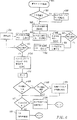
図6は、チャネル割当への適応方法の流れ線図を示す。
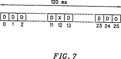
図7は、GSMトラフィックチャネルパケットのフォーマットを示す。
発明の詳細な説明
既に述べたパーソナル携帯電話システムを例にとって、セルラーシステムでのチャネル割当のための方法を述べることとする。当業者には理解されるであろうが、説明する方法は、他の類似の通信システムにも適しており、本発明の精神と範囲を離れることなく適用することができ、説明に続く請求の範囲に示されているものにのみ限定されるものである。
既に述べたように、現存する通信システムプロトコルに悪影響を与えることなく、必要なときにシステム容量が増大されることが望ましい。理想的には、システムプロトコルに必要な変更は元のシステムの加入者に認識できる変更を必要とせず、セルステーションでの影響が最小であるような、拡張されることになる元のシステムにとって完全に透明な、付加されるものでなければならない。
一般的には、一つの共通周波数帯域を用いるステーション間の干渉を低減するため、RF接続を行うのに必要最小の出力が用いられるというのが望ましく、又政府の方針でもあるので、一つのPSとCSとの間の接続を確立させるためのプロトコルは何であれ、RF接続を確立し、使用する際に受け入れ可能な低送信出力を用いることが基本になるべきである。この必要条件を満たすために、一式の試験的PS送信出力レベルが、図2と3の段階(4)と(3)のそれぞれでPSにより導入されることになる。
これらの段階でSYNCバーストを送信するためにPSにより用いられる初期の出力レベルが、一般的にCSに許容可能な品質の受信には不足と思われる安全で低いレベルに設定されるなら、SYNCバーストの応答(図2の段階(5)、図3の段階(4))が無いことで、SYNCバースト送信出力レベルが低すぎることがPSに示されることになる。するとPSは、CSからSYNCが受信されない度毎に出力レベルを増大させ、SYNCバーストを再送信することができる。CSの送信したSYNCが最終的に受信されると、PSは、最後に用いた送信機出力レベルが十分であったことを知る。更に、SYNCバーストを送信するために用いられる最初のPS送信出力レベルと、それぞれの再送信のために用いられる増分(例えば+3dB)を標準化することにより、CSは、+3dB出力追加の回数が、リンクチャネル割当(図2の段階(3)、図3の段階(2))とPSの送信したSYNCバーストが受信される時間との間の経過時間に行われていることになるので、必要なPS送信機出力レベルを知ることになる。時間分割二重(TDD)システムにおける送信及び受信の伝播経路の想定される相互関係のため、CSは、PS送信機出力レベルを使って、PSと交信するためにCSで使われる最小の送信機出力レベル(すなわち、PSとCSの受信機感度の差を考慮した上で)を決定することができる。非TDDシステムに対しては、送信と受信の伝播経路における差異は、オンエアー測定とキャリブレーションの実行で説明できるであろう。
図5は、アップリンク(PSからCS)又はダウンリンク(CSからPS)同期化のためにRCRSTD−28により特定されるような、同期化バーストのスロット構造を示している。224ビット持続バーストは、
R-(4bits)any 4 bit pattern
SS-(2bits)fixed field 10
PR-(62bits)a fixed periodic preamble for both uplink and down link 0110011001100110...011001
UW-(32bits)a unique word for designating uplink synchronization as 01101011100010011001101011110000,or downlink synchronization as 01010000111011110010100110010011;
CI-(4bits)fixed field 1001;
CSID-(42bits)CS identification code;
PSID-(28bits)PS identification code;
IDL-(34bits)all zeros,idle bits 0...00;and
CRC-(16bits)cyclic redundancy code error detection.
を含む。
同期化信号が、セルラーシステムのそれぞれ独自のインプリメンテーションと異なる可能性があり、用いられる多重アクセス技術の形態にもよるであろうことを当業者は理解できるであろう。例えば、TDMAシステムでは、同期化バーストが着信データをサンプリングするのに最適な間隔を決定するために用いられ、FDMAシステムでは、同期化信号がいずれかの副搬送波周波数オフセットを決定するのに用いられ、SDMAシステムでは、同期化信号が要求するPSの空間サインを決定するのに用いられる。すべての場合において、目的は、最上質の接続を確立するために必要な多重送信及び信号予測のパラメータを確立することである。
接続を形成するときに用いられる放射出力の量を最小化することが、干渉を管理する際の重要な要素である。干渉は、共通チャネルの使用の故に近隣のセルラーシステムの間で発生することもあれば、チャネル割当ての間に完全な直交性が保てないためにセルラーシステム内で発生することもある。しかし、新しいチャネル割当ての直交性を保証するのは難しいので、接続プロトコルは、受容できないレベルのセル内干渉の生ずる可能性を最小にし、更にセル間の干渉を管理する実用的な方法を提供する必要がある。
セル内及びセル間の干渉を管理する基本的手段は、上述したように、放射出力を最小にするように適応手順を用いることである。システムのモデル化は、新しい接続の追加が現在のセルラー接続へ及ぼす影響を計算することにより、所定のチャネル割当の結果を予測するための方法を提供するもう1つの手段である。本モデルは、適切な放射出力と、チャネル特性と、チャネル割当のすべてを含んでいる現在の接続を考え、新しい接続チャネルの追加によって当然予期される干渉のレベルを予測する必要がある。
システムモデルが、全干渉レベルは閾値以下になるであろうことを示せば、チャネルは新しい接続に仮に割り当てられ、仮の接続が現在ある接続に受容できない干渉を引き起こすかどうか経験的に決定するため、CSとPS両方による試験(テスト)送信がなされる。試験送信の後には、セルラーシステムに受容できない干渉から回復する機会を与えるため、所定の間隔のポーズが設けられる。受容できない干渉状態が起こらなければ、仮の接続状態が解除されて、接続が確立される。そうでない場合、CSは、別の動作を決定しなければならない。代替案は何れかの原因による干渉を管理するのに必要なCS干渉管理プロトコルの一部分を形成する。プロトコルは、仮のLCHを他チャネルへ再割当すること、チャネル割当のよりよい分散を達成するために現在の接続を再割当すること、又はその時点でチャネル容量が使用不可能であることを新しい接続を要求するPSへ助言すること等のオプションを含んでいてもよい。
図6は、チャネルを適応できるように割り当てるための好適な実施方法500を要約するフローチャートである。本方法は、ARIB標準、バージョン2、RCR STD−28に記載されているパーソナル携帯電話システム用接続プロトコルと互換性をもたせるため、下方互換性を提供する簡単な追加の他には、これらの標準に何ら修正を加える必要がないように設計されている。
図6ついていえば、適応性チャネル割当のための方法500が始まると、段階501で、CSが接続要求の発信元かどうか調べて、そうであれば段階502へ進み、CSがPCHで選択されたPSをPCHでページングし、その後段階503へ移る。段階503では、選択されたPSが、そのページングに応えてリンクチャネル確立要求(LCR)メッセージをSCCHでCSへ送信する。段階505では、CSは、使用可能なトラフィックチャネルから最適候補のリンクチャネル(LCH)を選択し、選択したものを仮の割当LCHとしてSCCHで送信する。この接続時には、選択されたPSが、段階511で、受信品質がCSにとって受容できるレベルであると予測される、できるだけ最低の出力レベルに近い、所定の低出力レベルで、仮のLCHでSYNCバーストを送信する。段階513で、選択されたPSは、CSが受容できる品質の受信を確立するためにPSが十分な出力を使用していることを示すSYNCバーストがCSから戻されてきているかどうかを調べる。戻されてきていなければ、PSは段階512で送信機出力レベルを増やし(通常+3dB)、段階511へ戻る。何回かの3dBの出力の増加は、段階512で確立される出力レベルが、品質のある受信ために必要な最低の3dBの出力以内にあるであろうということを保証する。出力の増加幅が小さいほど、確立される出力レベルを望ましい最低の出力レベル(例えば、+1dBの増大は、確立される出力レベルが最低値の26%以内であることを保証する)に近づけることができる。その間に段階506で、CSは仮のLCHでPSのSYNCバースト送信を聞き、SYNCバーストが受け入れ可能な品質で受信されるまで、テスト段階507を含むウエイトループに入る。SYNCバーストを受信した後、段階508では、CSは、段階505でのCSのLCH割当と段階507での受容できる品質のSYNCバーストの受信との間の経過時間に基づいて、CS送信出力レベルを計算する。(PSのSYNCバーストの送信は所定の間隔(通常は-5ms)で繰り返されるので、PS送信機に必要な出力は計算でき、mを出力増加の回数、P0を所定の初期PS送信機出力として、+3dBの増加に必要な出力は2m-1P0となる。)段階510では、CSが、段階508の計算に基づく出力レベルを使ってSYNCバーストを送信する。段階514では、CSのSYNCバーストを受信すると、選択されたPSとCSが、50%デューティサイクル・オン-オフバーストで構成される一連のアイドルトラフィックバーストを通常は毎秒200バーストの速度で、通常は10バーストインターバル間続けて送信する。(一つのPHSアイドルトラフィックバースト信号は所定のチャネルが何らのユーザーデータも搬送しないことを示すのに用いられる。)アイドルトラフィックバーストを送信した後、段階515で、段階514の試験信号送信から生じた何らかの受容できない干渉をシステムに報告させるための、所定時間(通常50ms)のポーズが導入される。セル間干渉が生じても(段階516)セルステーション間の通信が使用可能であれば(段階520)、付近のCSは、全ての受容できない干渉を新しいコールを使ってCSに報告するために段階515でポーズを用いることができる。セル間のCS通信(段階520)がなければ、受容できない干渉を経験している付近のセルは、段階521で、結果的に生じている干渉の「コスト」を最小にするため、段階521で、干渉管理プロトコルから所定の手順を呼び出す。段階517で、CSは新しいコールを使って、(交信のあるあらゆる近隣のセルを含め)現在ある接続の何れかに受容できない干渉を生じていないかどうか調べ、無ければ、CSは、段階518で、仮に割り当てられたLCHを新しい接続として扱う。そうでない場合、CSは、段階518で、結果的に生じている干渉の「コスト」を最小にするため、干渉管理プロトコルから所定の手順を呼び出す。従来技術でよく知られているように、干渉管理プロトコルには、チャネル再割当及び/又は他の近隣CSへのハンドオフのような多数の調整手順を含ませておくことができる。
50%デューティサイクルのアイドルトラフィックバーストが、新しい接続が確立されたことを通知するための所定のテスト又は試験信号の例として用いられたが、信号インターバルが散在しないアイドルチャネルトラフィックバーストの異なるシーケンスを使っている他の信号を用いてもよい。アイドルトラフィックバーストは、所定のチャネルでユーザーデータは搬送されないことを示すが、信号インターバルが散在しないアイドルトラフィックバーストの所定のシーケンスは、追加の非ユーザーデータ情報を搬送するように設計することもできる。例えば、特定のシーケンスパターンを有する試験信号を、接続を確立しようとしているメッセージが急用(例えば「911」コール)メッセージであり、最優先されるべきであることを全ステーションに伝えるために選択することもできる。これにより、受容できないレベルの干渉を経験する全セルラーステーションは、最優先メッセージに適する干渉プロトコルを呼び出すことができるようになる。散在するアイドルトラフィックバーストと無信号インターバルの明確なシーケンスパターンのセットを定めることにより、複数の優先メッセージレベルを作り出すこともできる。
図6に示されている方法を明確に説明するという目的のために、PHSシステムの特定の特性を用いていることを理解頂きたい。しかし、既に述べたように、記載された方法は他のセルラーシステムに適用することも可能であり、その適用性は当業者に明らかであろう。本方法は、1992年、フランス、パレゾーF−91120、ルイーズ・ブルュノー通り、49で著者が出版した、モウリー、Mとパウテット、M共著「移動体通信用GSMシステム」に記載の広く普及されているセルラー通信システムGSM(移動体通信用グローバルシステム)のようなセルラーシステムに適用することができる。
例えば、GSMは、図7に示されるように、双方向のデータと着信信号化のためのトラフィックチャネル(TCH)パケット構成を含む。この構成は、PHS内のアイドルトラフィックバーストと同じ目的で、干渉試験信号を送信するのに用いることができ、すなわち、新しい接続が確立されつつあるという一つの早期警告として使用し、その接続から受容できない干渉が生じるかどうか決定するためにしようすることができる。図7のTHCサイクルは、120msの期間にわたる26個バーストで構成され、ポジション0−11及び13−24で、2つの連続する24個のデータバーストDに編成されている。ポジション12のバーストXは、低速関連制御チャネル(SACCH)双方向信号化のために割り当てられており、ポジション25のバーストOは、送信が起こらない空白のバーストである。
GSM接続内の信号化は、二つの方法で調整でき、すなわち、ユーザーデータのバーストと接続しているSACCHを用いるか、もしくは、ユーザデータが送信されていないとき、呼び出しの初期設定の間に所定のチャネルで信号化するために、一つ又はそれ以上の全サイクルを用いる方法である。GSM受信機は「スティーリング」フラグ(モウリー他著作物引用、190頁)と呼ばれるTCHで送信される2進情報を読み取ることによって両モードを区別できる。従って、先にそして図6の段階514で述べたように呼び出しの初期設定の間に、SACCHバースト又は全GSM TCHサイクル(図7)のどちらかを、機能的にはPHSのアイドルトラフィックバースト試験信号と等価である試験信号の双方向送信に用いることができる。送信機出力レベルを決定し、ポーズを置くための段階は、通信プロトコルとは独立しているので、本方法全体を、現在あるプロトコルを変更することなしに、GSMのセルラーシステムに加えことができる。
チャネルを適合できるように割り当てるために記載した本方法は、説明を明確にするため、特定のセルラー通信システムに限定して述べたが、当業者には、本発明をその精神と範囲から逸脱することなく、無線ローカルエリアネットワーク(LAN)のような他の同様の通信システムへ適用できることは明らかであり、本発明は、以下の請求の範囲に提示されていることのみによって限定されるものである。TECHNICAL FIELD OF THE INVENTION
This channel allocation adaptation method relates to the allocation of traffic channels in a wireless communication system, in particular a cellular having a base station and a set of subscriber stations, a wireless local loop, and a personal communication system.
Explanation of related technology
A cell in a typical cellular telecommunications system receives an incoming telephone ground line, and its incoming voice on a radio frequency (RF) carrier that is broadcast by an antenna system to the area that the cell is designated to cover. It is configured around a cell station (often referred to as a base station) equipped with a multiplex transmitter for multiplex transmission of lines. Each set of individual subscriber stations is each equipped to receive a broadcast modulated carrier and demultiplex a particular channel carrying data that is scheduled to be received. Often, two-way conversations are supported by full-duplex transmission schemes on each traffic channel. Therefore, beacon traffic channels are used within the context of full-duplex transmission schemes. The uplink traffic channel is the part of the traffic channel that carries data from the subscriber station to the cell station, and the downlink traffic channel is the part of the traffic channel that carries data from the cell station to the subscriber station.
In a typical wireless communication system, the allocated RF frequency bandwidth is shared by multiple subscribers using various multiple access technologies. Typically, frequency division multiple access (FDMA) and time division multiple access (TDMA) techniques are used to share bandwidth allocated to multiple subscribers. FDMA subdivides the available bandwidth into multiple secondary bands. Each secondary band contains a carrier wave modulated by subscriber data. In TDMA, multiplex transmission of a plurality of subscribers is performed by time division in which each subscriber included in one connection is assigned a periodic time slot for transmitting data as a packet. Recently, code has been used to accommodate multiple subscribers on a single carrier (or subcarrier) to which each subscriber is assigned a code waveform used to modulate the carrier for each bit of digital data. A division multiple access (CDMA) method has been introduced. Each active subscriber having an assigned code waveform taken from a set of orthogonal waveforms can separate (demodulate) the system into individual subscriber transmissions.
Cellular communication systems allow cell station antenna arrays to be increased without increasing the allocated RF bandwidth (Roy III et al., US Pat. No. 5,515,378) in systems using FDMA, TDMA, and / or CDMA methods. It may include the use of recently introduced Space Division Multiple Access (SDMA) technology, which can be used to increase the capacity of the subscriber system. SDMA takes advantage of subscriber spatial distribution to increase the usable system capacity. Since subscribers tend to be distributed across the cell area, each subscriber can see how the cell station antenna array receives signals from the subscriber cell station antenna array and how the subscriber cell station antenna array. It will have its own spatial signature that characterizes whether it sends a signal to. As a result, the effective antenna gain in or near each active subscriber direction is optimized, i.e., the maximum value of the lobe is created for each direction or neighborhood, and also By determining the spatial signature, the cell station determines the radiation of the cell station antenna array so that each lobe is sufficiently narrow so that each active subscriber can be separated at the cell station for both transmission and reception. It has a potential for controlling the pattern. The data required to perform SDNA (referred to as the subscriber's spatial signature) is obtained empirically from transmissions received at the cell station from each active subscriber. In the context of the present invention, non-spatial multiplex transmissions (eg, FDMA, TDMA, and CDMA) are referred to as SDMA in the context of the present invention when used in combination with controllable antenna array patterns that are controlled by using spatial signatures. Please keep in mind. (In fact, spatial signatures and antenna arrays can be used in non-spatial division multiple access system configurations to improve communication between cell stations and subscribers using spatial signal processing techniques. In these cases, Labeled SDMA will also be used in the description of the invention below.)
The actual system can consist of one or some combination of CDMA, FDMA and TDMA technologies. For example, a combination of FDMA and TDMA techniques can be used in a system where a set of secondary bands are further subdivided into time slots.
When using a spatial signature, one or more subscribers can use a given packet time slot if the antenna arrangement is an effective radiation pattern. For example, the effective radiation pattern of the first subscriber results in a relatively low energy “zero” near the second subscriber sharing the packet time position, and the second subscriber's spatial signature is If a "zero" result results near the subscriber, simultaneous RF packet transmission will not cause any interference with reception at the two subscriber stations. Also, transmissions from the two subscribers to the cell station can be separated at the cell station. Under these ideal conditions, the spatial signature is said to represent an “orthogonal” implementation.
The concept of orthogonality also applies to FDMA and TDMA systems. All subcarrier channels are orthogonal to each other if each subcarrier in FDMA is completely separated so that the modulation data in any subcarrier does not affect the data that modulates any other subcarrier. Yes. Similarly, in a TDMA system, the channels are orthogonal to each other if each subscriber channel assigned packet data does not affect other active channels.
Orthogonality can be broken in each of these multiple access systems. For example, the interference that occurs in the channel is from carrier frequency offsets and imperfect filters in FDMA systems, from clocking errors and instabilities in TDMA systems, from synchronization inaccuracies or RF multipaths in CDMA systems, and from SDMA systems. Resulting from antenna pattern leakage caused by an antenna array of finite specifications. In an actual system that will include hundreds of subscriber stations, the system design may require complexity and cost, so complete orthogonality between all subscriber stations may not be guaranteed. . The basic motivation for using cellular systems is the reuse of the same RF spectrum in cell areas assigned to different locations. This principle of frequency reuse causes cell-to-cell interference that can severely degrade communication quality if not carefully controlled, and ultimately limits system capacity.
Because of the brittle nature of orthogonality and the interference caused by cellular frequency reuse, all cellular multiple access communication systems are disadvantageous caused by imperfect orthogonality between channels when new subscriber connections are added to the system. What is needed is a method for channel assignment that minimizes the impact.
Also, since the fundamental means for minimizing interference is the management of radiated power, the radiated power used by both subscriber stations and cell stations to minimize any interference that occurs in any practical multiple access communication system. It is important to minimize Also, any practical implementation must be aware that RF transmission in one cell can create interference in other nearby cells, and is perfectly orthogonal between adjacent cellular systems. The cellular system is generally unrealistic and direct real-time communication between neighboring cell stations may not be possible, so a cellular system further requires operating one cellular system and other cellular systems in the vicinity. Is to provide a method for minimizing the unfavorable consequences of any interference arising in Since real-time communication between cells between cell stations may not exist or may not be possible, even if there is no direct real-time communication between cell stations, minimize the adverse effects of intercellular interference Need to think about.
A specific example of an existing protocol for establishing a connection (FIG. 1) between a subscriber station and a cell station in a cellular communication system is the radio approved at the December 1995 Standards Assembly Conference. Examples include those used in the “personal mobile phone system” described in the Preliminary Standard of the Association of Commerce and Industry (ARIB), the second edition, RCRSTD-28.
The system described in the ARIB Preliminary Standard, 2nd Edition, is a pre-defined system for communicating over a RF carrier between a plurality of geographically distributed personal mobile phone stations (PSs) and a cell station (CS). A digital wireless personal communication system for servicing PSs in a cell and for interfacing with standard telecommunication circuit equipment. The system consists of (a) 77 RF carriers over the public system RF band at 1895-1918 MHz, spaced apart by 300 kHz, and (b) phase shifts in multiples of π / 4 radians for each symbol period. (C) 4 duplex TDMA-TDD (Time Division Multiple Access, Time Division Duplex) RF access per RF carrier, (d) 384 kbits / s And (e) a 5 ms frame length with 120 symbols per slot (including guard bits).
The control sequence for setting up and establishing an incoming call from the CS to the PS is shown in FIG. This incoming call connection establishment phase consists of (1) paging of CS on the paging channel (PCH) of the selected PS that requires an incoming connection, and (2) signaling control channel ( Response of the selected PS on SCCH) and (3) PS request of CS by selecting traffic channel (TCH) and sending TCH selected as link channel (LCH) assignment to PS on SCCH And (4) the selected PS switches to the assigned LHC and sends a series of synchronization (SYNC) burst signals followed by a series of idle traffic bursts; (5) successfully Upon detecting the synchronization signal, the CS sends a series of SYNC bursts on the LCH followed by a series of idle traffic bursts. Next, the process proceeds to establish a connection with the incoming call to the CS, it may be required additional option signal (e.g., encryption and user authentication) including, respond by drawing.
The PCH is a one-way downlink channel from one point to multiple points (point-to-multipoint) in which the CS transmits the same information to all PSs in the paging area. SCCH is a bi-directional point-to-point channel that transmits information necessary for call connection between CS and one PS. The TCH is a point-to-point bi-directional channel for transmitting user (subscriber) information.
The problems with the current procedure are that the current procedure does not provide for setting the transmitter power level suitable for each connection and the impact of interference that may result from a new connection to the current subscriber. It is not to work on.
FIG. 3 shows a control procedure for establishing an uplink connection that is initiated by the PS requesting establishment of a connection with the CS. The steps are: (1) PS sends link channel establishment request on signaling control channel (SCCH); (2) CS selects traffic channel (TCH) and is selected as link channel (LCH) assignment Responding to the PS request by sending the TCH to the PS on the SCCH, and (3) switching to the LCH to which the PS is assigned, and a series of synchronization (SYNC) burst signals followed by a series of idle traffic bursts. (4) Upon successful detection of the synchronization signal, the CS sends a series of SYNC bursts followed by a series of idle traffic bursts on the LCH, and then the connection with the incoming call to the CS. Proceed with establishment and pull out additional optional signals (eg encryption and user authentication) that may be needed Including the steps of responding by the.
Similar to the above procedure for establishing a downlink connection, the procedure for establishing an uplink connection has the same drawbacks, i.e., a method for establishing the transmitter power level required for proper communication, and the current It has the disadvantage of lacking a way to assess the impact of the interference created by establishing a new connection to the user.
The control procedure used to establish a connection with one PS uses common and individually assigned time slots. FIG. 4 shows time slot assignments used for transmission and reception in a TDMA-TDD system. The time structure of each TDD carrier is organized into 5 ms frames that are each divided into 8 segments. Each segment supports a one-way audio channel of 32 kbits / s (excluding overhead). FIG. 4 is an example showing activity in a common 5 ms frame when two PSs (PS (1) and PS (2), assigned to
Summary of the Invention
The present invention is directed to a method for making a connection in a cellular system using multiplex transmission technology for the effective use of available bandwidth as defined by law. The method is part of a new protocol or addition to an existing protocol for establishing a connection between a cell station and a subscriber station. When added to an existing protocol, the method is fully compatible with the standard protocol used in cellular systems and is not completely visible to all users of current cellular systems.
In response to a connection request from an external communication network connected to the CS, a method for establishing an incoming call connection from the CS to a selected PS in the cellular system includes: (1) the CS is a downlink connection Paging on the paging channel (PCH) of the selected PS that requires: (2) the selected PS responding to the signaling control channel (SCCH) by sending a link channel establishment request; (3) the CS responds to the PS request by selecting the traffic channel (TCH) as the temporary link channel (LCH) and transmitting the temporary LCH assignment to the PS on the SCCH; and (4) the selected PS. Switch to assigned LCH and synchronize (SYNC) with a predetermined initial power level for initial transmission of SYNC bursts Repeatedly transmit a burst signal, and successively increase the power level with each repeated SYNC burst transmission until the SYNC burst is successfully received from the CS, then transmit a series of idle traffic bursts and establish a connection The final power level used for the SYNC burst is used for all subsequent transmissions to the CS, and (5) when receiving a qualitative quality SYNC burst (PS SYNC burst) transmitted by the PS. CS calculates the required PS transmission power based on the time delay between the transmission of the provisional link channel assignment of the CS and the successful reception of the SYNC burst of the appropriate quality PS, and the CS A series of idle traffic using the PS transmission power calculated as a guide for the CS transmission power required for proper communication with Responds by sending a SYNC burst followed by a Cburst on the LCH and initiates the connection with the incoming call to the CS after invoking all necessary additional optional protocols (eg encryption and user authorization) Including stages.
With this method, an appropriate PS transmission power level required for communication with the CS is established. If the subscriber power level is increased by a small amount, the subscriber power level corresponding to the CS reception of the proper SYNC burst can be close to the desired minimum PS transmission power required for the connection. Sending a known test pattern (eg PHS idle traffic burst) to early alert other users of the same frequency, time, code or spatial channel of the cellular system that a new connection has been established Become. Pauses after known test patterns can be used to evaluate whether there is an unacceptable level of interference in connections within the cell and to perform the necessary handoffs. Early warning will alert neighboring cells that a new connection in the neighboring cell requires channel reassignment if an unacceptable level of interference has occurred.
A similar method is used when one PS wants to establish an outgoing connection through CS. Since this process is started by sending a link channel establishment request on the SCCH as in step (2), this step is already done, except that step (1) is not used. Same as outlined.
In this method, the entire method is compatible with standard protocols such as those used in personal mobile phone systems and does not interfere with it at all.
It will be understood that various modifications can be made to the above description of the invention without departing from the scope and spirit of the invention. For example, the logical control channels PCH and SCCH may be the same physical channel. The particular method described above relates to a PHS system for more clearly describing the application of the present invention using a particular cellular system. It will be apparent to those skilled in the art that various modifications can be made in view of the following drawings and detailed description.
[Brief description of the drawings]
FIG. 1 shows the relationship between a personal station (PS) and a cell station (CS) in a personal mobile phone system.
FIG. 2 illustrates a method for establishing an incoming call connection from a CS to a PS in a personal mobile phone system.
FIG. 3 illustrates a method for establishing an outgoing call connection from a PS to a CS in a personal mobile phone system.
FIG. 4 shows slot assignment of TDD frames.
FIG. 5 shows a bit allocation pattern of the synchronization burst.
FIG. 6 shows a flow diagram of an adaptation method for channel assignment.
FIG. 7 shows the format of a GSM traffic channel packet.
Detailed Description of the Invention
Taking the personal mobile phone system already described as an example, a method for channel assignment in a cellular system will be described. As will be appreciated by those skilled in the art, the described method is suitable for other similar communication systems and can be applied without departing from the spirit and scope of the present invention. It is limited only to what is shown in the range.
As already mentioned, it is desirable to increase system capacity when needed without adversely affecting existing communication system protocols. Ideally, the required changes to the system protocol do not require changes that are visible to the original system's subscribers, and are complete for the original system to be extended with minimal impact at the cell station. It must be transparent and added to.
In general, it is desirable that the minimum power required to make an RF connection be used to reduce interference between stations using one common frequency band, and it is also a government policy, so one PS Whatever protocol is used to establish the connection between CS and CS, it should be fundamental to use an acceptable low transmission power when establishing and using an RF connection. To meet this requirement, a set of experimental PS transmission power levels will be introduced by the PS at each of steps (4) and (3) in FIGS.
If the initial power level used by the PS to transmit a SYNC burst at these stages is set to a safe and low level that would generally be insufficient for quality acceptable to the CS, the SYNC burst 2 (step (5) in FIG. 2, step (4) in FIG. 3) indicates that the SYNC burst transmission output level is too low. The PS can then increase the power level every time SYNC is not received from the CS and retransmit the SYNC burst. When the SYNC transmitted by the CS is finally received, the PS knows that the last used transmitter power level was sufficient. In addition, by standardizing the initial PS transmit power level used to transmit a SYNC burst and the increment used for each retransmission (eg, +3 dB), the CS can add +3 dB power additions to the link Since it is performed at the elapsed time between channel allocation (step (3) in FIG. 2, step (2) in FIG. 3) and the time when the SYNC burst transmitted by the PS is received, the necessary PS You will know the transmitter output level. Due to the assumed correlation of transmission and reception propagation paths in a time division duplex (TDD) system, the CS uses the PS transmitter power level and is the smallest transmitter used by the CS to communicate with the PS. The output level (ie, taking into account the difference in PS and CS receiver sensitivity) can be determined. For non-TDD systems, differences in transmission and reception propagation paths may be explained by performing on-air measurements and calibration.
FIG. 5 shows the slot structure of the synchronization burst as specified by RCRSTD-28 for uplink (PS to CS) or downlink (CS to PS) synchronization. A 224 bit sustained burst is
R- (4bits) any 4 bit pattern
SS- (2bits) fixed field 10
PR- (62bits) a fixed periodic preamble for both uplink and down link 0110011001100110 ... 011001
UW- (32bits) a unique word for designating uplink synchronization as 01101011100010011001101011110000, or downlink synchronization as 01010000111011110010100110010011;
CI- (4bits) fixed field 1001;
CSID- (42bits) CS identification code;
PSID- (28bits) PS identification code;
IDL- (34bits) all zeros,
CRC- (16bits) cyclic redundancy code error detection.
including.
One skilled in the art will appreciate that the synchronization signal may be different from each unique implementation of the cellular system and will depend on the form of multiple access technology used. For example, in TDMA systems, synchronization bursts are used to determine the optimal interval for sampling incoming data, and in FDMA systems, synchronization signals are used to determine any subcarrier frequency offset. In an SDMA system, it is used to determine the spatial signature of the PS required by the synchronization signal. In all cases, the goal is to establish the multiplexing and signal prediction parameters necessary to establish the highest quality connection.
Minimizing the amount of radiant power used when forming the connection is an important factor in managing interference. Interference can occur between neighboring cellular systems due to the use of a common channel, or it can occur within cellular systems because perfect orthogonality cannot be maintained during channel assignment. However, since it is difficult to ensure orthogonality of new channel assignments, the connection protocol minimizes the possibility of unacceptable levels of intra-cell interference and provides a practical way to manage inter-cell interference. There is a need.
The basic means of managing intra-cell and inter-cell interference is to use an adaptive procedure to minimize the radiation output, as described above. System modeling is another means of providing a method for predicting the outcome of a given channel assignment by calculating the effect of the addition of a new connection on the current cellular connection. The model needs to predict the level of interference that is naturally expected by the addition of a new connection channel, considering the current connection including all of the appropriate radiated power, channel characteristics, and channel assignments.
If the system model shows that the total interference level will be below the threshold, then the channel is tentatively assigned to a new connection and empirically determined whether the tentative connection causes unacceptable interference to the existing connection. , Test transmission by both CS and PS is performed. After the test transmission, a predetermined interval pause is provided to give the cellular system the opportunity to recover from unacceptable interference. If an unacceptable interference state does not occur, the temporary connection state is released and the connection is established. Otherwise, the CS must decide another action. The alternative forms part of the CS interference management protocol necessary to manage interference due to any cause. The protocol re-assigns the temporary LCH to another channel, re-assigns the current connection to achieve better distribution of channel assignments, or new channel capacity is not available at that time. Options such as advising the PS requesting the connection may be included.
FIG. 6 is a flow chart summarizing a
Referring to FIG. 6, when the
An idle traffic burst with a 50% duty cycle was used as an example of a predetermined test or test signal to notify that a new connection was established, but using a different sequence of idle channel traffic bursts with no interspersed signal intervals Other signals may be used. Although idle traffic bursts indicate that no user data is carried on a given channel, a given sequence of idle traffic bursts that are not interspersed with signal intervals can also be designed to carry additional non-user data information. For example, selecting a test signal with a specific sequence pattern to tell all stations that the message attempting to establish a connection is an urgent (eg, “911” call) message and should be given top priority. You can also. This allows all cellular stations that experience an unacceptable level of interference to invoke the interference protocol appropriate for the highest priority message. Multiple priority message levels can be created by defining a set of distinct sequence patterns of scattered idle traffic bursts and no-signal intervals.
It should be understood that the specific characteristics of the PHS system are used for the purpose of clearly illustrating the method shown in FIG. However, as already mentioned, the described method can also be applied to other cellular systems, and its applicability will be apparent to those skilled in the art. This method is widely used as described in "GSM System for Mobile Communications", published by Mourie, M and Pawtet, M, published by the author in 1992, Palaiseau F-91120, Avenue Louise Bruuno, 49 The present invention can be applied to a cellular system such as a cellular communication system GSM (Global System for Mobile Communication).
For example, GSM includes a traffic channel (TCH) packet structure for bidirectional data and incoming signaling as shown in FIG. This configuration can be used to transmit interference test signals for the same purpose as idle traffic bursts in the PHS, i.e., as an early warning that a new connection is being established and accepted from that connection. Can be used to determine if there is an impossible interference. The THC cycle of FIG. 7 consists of 26 bursts over a period of 120 ms and is organized into two consecutive 24 data bursts D at positions 0-11 and 13-24. The burst X at position 12 is allocated for low-speed associated control channel (SACCH) bi-directional signaling, and the burst O at
Signaling within the GSM connection can be adjusted in two ways: using a SACCH connected to a burst of user data, or when user data is not being transmitted, during the initial setup of the call This is a method that uses one or more full cycles to signal on multiple channels. The GSM receiver can distinguish between the two modes by reading binary information transmitted on the TCH called the “Steeling” flag (Mowley et al., Citation 190). Thus, during the initial setup of the call as described above and at
Although the method described for assigning channels adaptively has been described for the sake of clarity and limited to a particular cellular communication system, those skilled in the art will depart from the spirit and scope of the present invention. It is clear that it can be applied to other similar communication systems, such as a wireless local area network (LAN), and the present invention is limited only by what is presented in the following claims. .
Claims (15)
Applications Claiming Priority (3)
| Application Number | Priority Date | Filing Date | Title |
|---|---|---|---|
| US08/729,387 US6047189A (en) | 1996-10-11 | 1996-10-11 | Adaptive method for channel assignment in a cellular communication system |
| US08/729,387 | 1996-10-11 | ||
| PCT/US1997/018612 WO1998017020A1 (en) | 1996-10-11 | 1997-10-10 | An adaptive method for channel assignment in a cellular communication system |
Publications (3)
| Publication Number | Publication Date |
|---|---|
| JP2001506065A JP2001506065A (en) | 2001-05-08 |
| JP2001506065A5 JP2001506065A5 (en) | 2005-06-16 |
| JP4151990B2 true JP4151990B2 (en) | 2008-09-17 |
Family
ID=24930801
Family Applications (1)
| Application Number | Title | Priority Date | Filing Date |
|---|---|---|---|
| JP51856798A Expired - Lifetime JP4151990B2 (en) | 1996-10-11 | 1997-10-10 | Adapting method for channel assignment in cellular communication systems |
Country Status (10)
| Country | Link |
|---|---|
| US (1) | US6047189A (en) |
| EP (1) | EP1013013B1 (en) |
| JP (1) | JP4151990B2 (en) |
| CN (1) | CN1118969C (en) |
| AT (1) | ATE301353T1 (en) |
| AU (1) | AU4757797A (en) |
| BR (1) | BR9712288A (en) |
| CA (1) | CA2268269C (en) |
| DE (1) | DE69733903T2 (en) |
| WO (1) | WO1998017020A1 (en) |
Cited By (1)
| Publication number | Priority date | Publication date | Assignee | Title |
|---|---|---|---|---|
| US8064944B2 (en) | 1996-10-11 | 2011-11-22 | Intel Corporation | Power control with signal quality estimation for smart antenna communications systems |
Families Citing this family (98)
| Publication number | Priority date | Publication date | Assignee | Title |
|---|---|---|---|---|
| JP3666155B2 (en) * | 1996-12-26 | 2005-06-29 | ソニー株式会社 | COMMUNICATION METHOD, TRANSMISSION DEVICE, AND RECEPTION DEVICE |
| SE521614C2 (en) * | 1997-08-28 | 2003-11-18 | Ericsson Telefon Ab L M | Method and apparatus for radio power allocation and distribution |
| FI106665B (en) * | 1997-11-05 | 2001-03-15 | Nokia Mobile Phones Ltd | A method and arrangement for determining transmit power in a mobile station |
| FI980229A (en) * | 1998-02-02 | 1999-08-03 | Nokia Networks Oy | A method for handling a traffic channel request |
| DE19811825B4 (en) * | 1998-03-18 | 2004-09-16 | Telefonaktiebolaget Lm Ericsson (Publ) | Communication system with a limited number of communication channels |
| US6452915B1 (en) | 1998-07-10 | 2002-09-17 | Malibu Networks, Inc. | IP-flow classification in a wireless point to multi-point (PTMP) transmission system |
| US6862622B2 (en) * | 1998-07-10 | 2005-03-01 | Van Drebbel Mariner Llc | Transmission control protocol/internet protocol (TCP/IP) packet-centric wireless point to multi-point (PTMP) transmission system architecture |
| GB2347828B (en) * | 1999-03-05 | 2004-05-19 | Internat Mobile Satellite Orga | Communication methods and apparatus |
| US6167273A (en) * | 1999-04-28 | 2000-12-26 | Nokia Mobile Phones Ltd. | Apparatus, and associated method, for effectuating power control to maintain desired QoS levels in the performance of a communication service |
| US20090219879A1 (en) | 1999-05-21 | 2009-09-03 | Wi-Lan, Inc. | Method and apparatus for bandwidth request/grant protocols in a wireless communication system |
| US8462810B2 (en) | 1999-05-21 | 2013-06-11 | Wi-Lan, Inc. | Method and system for adaptively obtaining bandwidth allocation requests |
| US7006530B2 (en) | 2000-12-22 | 2006-02-28 | Wi-Lan, Inc. | Method and system for adaptively obtaining bandwidth allocation requests |
| US6925068B1 (en) | 1999-05-21 | 2005-08-02 | Wi-Lan, Inc. | Method and apparatus for allocating bandwidth in a wireless communication system |
| KR20010026038A (en) * | 1999-09-02 | 2001-04-06 | 서평원 | Effective Radiated Power Limitation Method in Radio Communication System |
| SE515638C2 (en) * | 2000-01-21 | 2001-09-17 | Ericsson Telefon Ab L M | Procedure in a mobile telecommunication system |
| US8321542B1 (en) * | 2000-05-05 | 2012-11-27 | Ipr Licensing, Inc. | Wireless channel allocation in a base station processor |
| FI20001133A (en) * | 2000-05-12 | 2001-11-13 | Nokia Corp | Method for arranging data transfer between data terminals and a link station in a communication system |
| US8363744B2 (en) | 2001-06-10 | 2013-01-29 | Aloft Media, Llc | Method and system for robust, secure, and high-efficiency voice and packet transmission over ad-hoc, mesh, and MIMO communication networks |
| JP3738205B2 (en) * | 2000-08-12 | 2006-01-25 | 三星電子株式会社 | Network transmission power optimization apparatus and method |
| US6954641B2 (en) * | 2000-08-14 | 2005-10-11 | Vesivius, Inc. | Communique wireless subscriber device for a cellular communication network |
| US7024200B2 (en) * | 2000-08-14 | 2006-04-04 | Vesuvius, Inc. | Communique system with active feedback for cellular communication networks |
| US6907023B2 (en) | 2000-08-14 | 2005-06-14 | Vesuvius, Inc. | Communique system with dynamic bandwidth allocation in cellular communication networks |
| US6937592B1 (en) * | 2000-09-01 | 2005-08-30 | Intel Corporation | Wireless communications system that supports multiple modes of operation |
| CN1135746C (en) * | 2000-10-19 | 2004-01-21 | 华为技术有限公司 | Multiple-job load monitoring and forecasting device in CDMA cellular communication system and its calculation method |
| DE60107797T2 (en) * | 2000-10-31 | 2005-06-09 | Kabushiki Kaisha Toshiba | Wireless communication system, weighting control arrangement, and weight vector generation method |
| GB2371712B (en) * | 2000-11-28 | 2004-09-29 | Nokia Networks Oy | Power change estimation for communication system |
| US6947748B2 (en) * | 2000-12-15 | 2005-09-20 | Adaptix, Inc. | OFDMA with adaptive subcarrier-cluster configuration and selective loading |
| CA2431849C (en) * | 2000-12-15 | 2013-07-30 | Broadstrom Telecommunications, Inc. | Multi-carrier communications with group-based subcarrier allocation |
| FI111599B (en) * | 2000-12-28 | 2003-08-15 | Nokia Corp | Method and apparatus for mobile telecommunications |
| JP4752113B2 (en) * | 2001-01-16 | 2011-08-17 | ソニー株式会社 | Electronic device and signal transmission method |
| GB0103274D0 (en) * | 2001-02-09 | 2001-03-28 | Nokia Networks Oy | A data communication system |
| JP2002247639A (en) | 2001-02-15 | 2002-08-30 | Ntt Docomo Inc | Wireless channel setting control method, wireless network controller, base station unit and mobile communication system |
| US7079847B2 (en) * | 2001-03-21 | 2006-07-18 | Agere Systems Inc. | Controller and transceiver employable in a wireless communications network |
| US6961545B2 (en) * | 2001-04-09 | 2005-11-01 | Atheros Communications, Inc. | Method and system for providing antenna diversity |
| GB2377596B (en) * | 2001-07-11 | 2004-09-01 | Cambridge Broadband Ltd | Communications protocol |
| NZ513942A (en) * | 2001-09-04 | 2001-09-28 | Tait Electronics Ltd | Power control in mobile radio communications |
| US7003310B1 (en) | 2001-09-28 | 2006-02-21 | Arraycomm Llc. | Coupled uplink/downlink power control and spatial processing with adaptive antenna arrays |
| US7333825B2 (en) * | 2001-10-17 | 2008-02-19 | Nokia Corporation | Apparatus, and associated method, for facilitating communication resource allocation in a packet radio communication system |
| TWI242335B (en) * | 2002-10-04 | 2005-10-21 | Winbond Electronics Corp | Wireless communication method for channel shared |
| US6894993B2 (en) * | 2002-12-27 | 2005-05-17 | Arraycomm, Inc. | Detection and correction of channel swap in spatial division multiple access systems |
| US8422380B2 (en) | 2003-03-26 | 2013-04-16 | Sharp Laboratories Of America, Inc. | Dynamically reconfigurable wired network |
| US7302278B2 (en) * | 2003-07-03 | 2007-11-27 | Rotani, Inc. | Method and apparatus for high throughput multiple radio sectorized wireless cell |
| US20050144307A1 (en) * | 2003-12-15 | 2005-06-30 | Qinghua Li | Back-end alignment to avoid SDMA ACK time-out |
| US20050111427A1 (en) * | 2003-11-21 | 2005-05-26 | Qinghua Li | SDMA training and operation |
| US7206550B2 (en) | 2003-12-29 | 2007-04-17 | Intel Corporation | Antenna subsystem calibration apparatus and methods in spatial-division multiple-access systems |
| US8369790B2 (en) | 2003-12-30 | 2013-02-05 | Intel Corporation | Communication overhead reduction apparatus, systems, and methods |
| US8452316B2 (en) * | 2004-06-18 | 2013-05-28 | Qualcomm Incorporated | Power control for a wireless communication system utilizing orthogonal multiplexing |
| US7197692B2 (en) | 2004-06-18 | 2007-03-27 | Qualcomm Incorporated | Robust erasure detection and erasure-rate-based closed loop power control |
| US7594151B2 (en) * | 2004-06-18 | 2009-09-22 | Qualcomm, Incorporated | Reverse link power control in an orthogonal system |
| US7536626B2 (en) | 2004-06-18 | 2009-05-19 | Qualcomm Incorporated | Power control using erasure techniques |
| US7263335B2 (en) * | 2004-07-19 | 2007-08-28 | Purewave Networks, Inc. | Multi-connection, non-simultaneous frequency diversity in radio communication systems |
| US7460839B2 (en) | 2004-07-19 | 2008-12-02 | Purewave Networks, Inc. | Non-simultaneous frequency diversity in radio communication systems |
| US7573851B2 (en) | 2004-12-07 | 2009-08-11 | Adaptix, Inc. | Method and system for switching antenna and channel assignments in broadband wireless networks |
| US8131647B2 (en) * | 2005-01-19 | 2012-03-06 | Amazon Technologies, Inc. | Method and system for providing annotations of a digital work |
| US9275052B2 (en) | 2005-01-19 | 2016-03-01 | Amazon Technologies, Inc. | Providing annotations of a digital work |
| US7742444B2 (en) * | 2005-03-15 | 2010-06-22 | Qualcomm Incorporated | Multiple other sector information combining for power control in a wireless communication system |
| US8942639B2 (en) | 2005-03-15 | 2015-01-27 | Qualcomm Incorporated | Interference control in a wireless communication system |
| US8848574B2 (en) | 2005-03-15 | 2014-09-30 | Qualcomm Incorporated | Interference control in a wireless communication system |
| US7242920B2 (en) * | 2005-05-31 | 2007-07-10 | Scenera Technologies, Llc | Methods, systems, and computer program products for controlling data transmission based on power cost |
| US9055552B2 (en) * | 2005-06-16 | 2015-06-09 | Qualcomm Incorporated | Quick paging channel with reduced probability of missed page |
| US8750908B2 (en) * | 2005-06-16 | 2014-06-10 | Qualcomm Incorporated | Quick paging channel with reduced probability of missed page |
| KR101097021B1 (en) * | 2005-10-27 | 2011-12-20 | 콸콤 인코포레이티드 | Method and apparatus for estimating reverse link loading in a wireless communication system |
| US20090207790A1 (en) | 2005-10-27 | 2009-08-20 | Qualcomm Incorporated | Method and apparatus for settingtuneawaystatus in an open state in wireless communication system |
| JP2009514429A (en) * | 2005-10-27 | 2009-04-02 | クゥアルコム・インコーポレイテッド | Method and apparatus for transmitting an access probe in a wireless communication system |
| US20070097935A1 (en) * | 2005-10-27 | 2007-05-03 | Alexei Gorokhov | In-band rate control for an orthogonal frequency division multiple access communication system |
| US20070147226A1 (en) * | 2005-10-27 | 2007-06-28 | Aamod Khandekar | Method and apparatus for achieving flexible bandwidth using variable guard bands |
| EP2464028A1 (en) | 2006-02-28 | 2012-06-13 | Rotani Inc. | Methods and apparatus for overlapping mimo antenna physical sectors |
| US8442572B2 (en) * | 2006-09-08 | 2013-05-14 | Qualcomm Incorporated | Method and apparatus for adjustments for delta-based power control in wireless communication systems |
| US8670777B2 (en) | 2006-09-08 | 2014-03-11 | Qualcomm Incorporated | Method and apparatus for fast other sector interference (OSI) adjustment |
| JP4777205B2 (en) * | 2006-09-28 | 2011-09-21 | 京セラ株式会社 | Wireless communication system, wireless communication terminal and base station |
| US9672533B1 (en) | 2006-09-29 | 2017-06-06 | Amazon Technologies, Inc. | Acquisition of an item based on a catalog presentation of items |
| US8725565B1 (en) | 2006-09-29 | 2014-05-13 | Amazon Technologies, Inc. | Expedited acquisition of a digital item following a sample presentation of the item |
| US7865817B2 (en) | 2006-12-29 | 2011-01-04 | Amazon Technologies, Inc. | Invariant referencing in digital works |
| US20080195962A1 (en) * | 2007-02-12 | 2008-08-14 | Lin Daniel J | Method and System for Remotely Controlling The Display of Photos in a Digital Picture Frame |
| US8024400B2 (en) | 2007-09-26 | 2011-09-20 | Oomble, Inc. | Method and system for transferring content from the web to mobile devices |
| US7751807B2 (en) | 2007-02-12 | 2010-07-06 | Oomble, Inc. | Method and system for a hosted mobile management service architecture |
| US7716224B2 (en) | 2007-03-29 | 2010-05-11 | Amazon Technologies, Inc. | Search and indexing on a user device |
| US9665529B1 (en) | 2007-03-29 | 2017-05-30 | Amazon Technologies, Inc. | Relative progress and event indicators |
| US8990215B1 (en) | 2007-05-21 | 2015-03-24 | Amazon Technologies, Inc. | Obtaining and verifying search indices |
| US20090124233A1 (en) * | 2007-11-09 | 2009-05-14 | Morris Robert P | Methods, Systems, And Computer Program Products For Controlling Data Transmission Based On Power Cost |
| US8423889B1 (en) | 2008-06-05 | 2013-04-16 | Amazon Technologies, Inc. | Device specific presentation control for electronic book reader devices |
| WO2010011084A2 (en) * | 2008-07-23 | 2010-01-28 | 엘지전자 주식회사 | Method for self-configuring a cellular infrastructure as desired, and a device therefor |
| TWI449387B (en) | 2008-08-29 | 2014-08-11 | Realtek Semiconductor Corp | Method and device for adjusting communicating power |
| CN101674658B (en) * | 2008-09-12 | 2011-11-30 | 中兴通讯股份有限公司 | Application method of space division multiplexing of high-speed downlink packet access system |
| US20100157821A1 (en) * | 2008-12-18 | 2010-06-24 | Morris Robert P | Methods, Systems, And Computer Program Products For Sending Data Units Based On A Measure Of Energy |
| US20100161777A1 (en) * | 2008-12-22 | 2010-06-24 | Morris Robert P | Method and System For Providing A Subscription To A Tuple Based On A Variable Identifier |
| US9087032B1 (en) | 2009-01-26 | 2015-07-21 | Amazon Technologies, Inc. | Aggregation of highlights |
| USD601559S1 (en) | 2009-01-27 | 2009-10-06 | Amazon Technologies, Inc. | Electronic reader device |
| US8378979B2 (en) | 2009-01-27 | 2013-02-19 | Amazon Technologies, Inc. | Electronic device with haptic feedback |
| USD636771S1 (en) | 2009-01-27 | 2011-04-26 | Amazon Technologies, Inc. | Control pad for an electronic device |
| US8832584B1 (en) | 2009-03-31 | 2014-09-09 | Amazon Technologies, Inc. | Questions on highlighted passages |
| USD624074S1 (en) | 2009-05-04 | 2010-09-21 | Amazon Technologies, Inc. | Electronic reader device |
| US8692763B1 (en) | 2009-09-28 | 2014-04-08 | John T. Kim | Last screen rendering for electronic book reader |
| US8626224B1 (en) * | 2010-02-03 | 2014-01-07 | Sprint Spectrum L.P. | Advanced transmit power correction |
| US9495322B1 (en) | 2010-09-21 | 2016-11-15 | Amazon Technologies, Inc. | Cover display |
| US9158741B1 (en) | 2011-10-28 | 2015-10-13 | Amazon Technologies, Inc. | Indicators for navigating digital works |
| CN103428750B (en) * | 2012-05-17 | 2016-05-11 | 中兴通讯股份有限公司 | A kind of method and the device of newly-built community to peripheral cell interference that reduce |
| CN107124394B (en) * | 2017-03-10 | 2020-03-20 | 北京国电通网络技术有限公司 | Power communication network security situation prediction method and system |
Family Cites Families (6)
| Publication number | Priority date | Publication date | Assignee | Title |
|---|---|---|---|---|
| US5276908A (en) * | 1990-10-25 | 1994-01-04 | Northern Telecom Limited | Call set-up and spectrum sharing in radio communication on systems with dynamic channel allocation |
| BR9206187A (en) * | 1991-06-25 | 1994-11-14 | Motorola Inc | Process to facilitate the use of specific base location and communication unit |
| EP0565507A3 (en) * | 1992-04-10 | 1994-11-30 | Ericsson Ge Mobile Communicat | Power control for random access call set-up in a mobile telephone system |
| US5367559A (en) * | 1992-05-11 | 1994-11-22 | Hughes Aircraft Company | Sequential power estimation for cellular system handoff |
| AU670955B2 (en) * | 1992-08-04 | 1996-08-08 | Koninklijke Philips Electronics N.V. | Mobile radio system |
| US5465399A (en) * | 1992-08-19 | 1995-11-07 | The Boeing Company | Apparatus and method for controlling transmitted power in a radio network |
-
1996
- 1996-10-11 US US08/729,387 patent/US6047189A/en not_active Expired - Lifetime
-
1997
- 1997-10-10 EP EP97910120A patent/EP1013013B1/en not_active Expired - Lifetime
- 1997-10-10 CN CN97198741A patent/CN1118969C/en not_active Expired - Lifetime
- 1997-10-10 CA CA002268269A patent/CA2268269C/en not_active Expired - Fee Related
- 1997-10-10 AU AU47577/97A patent/AU4757797A/en not_active Abandoned
- 1997-10-10 JP JP51856798A patent/JP4151990B2/en not_active Expired - Lifetime
- 1997-10-10 WO PCT/US1997/018612 patent/WO1998017020A1/en active IP Right Grant
- 1997-10-10 AT AT97910120T patent/ATE301353T1/en not_active IP Right Cessation
- 1997-10-10 BR BR9712288-2A patent/BR9712288A/en not_active Application Discontinuation
- 1997-10-10 DE DE69733903T patent/DE69733903T2/en not_active Expired - Lifetime
Cited By (1)
| Publication number | Priority date | Publication date | Assignee | Title |
|---|---|---|---|---|
| US8064944B2 (en) | 1996-10-11 | 2011-11-22 | Intel Corporation | Power control with signal quality estimation for smart antenna communications systems |
Also Published As
| Publication number | Publication date |
|---|---|
| CA2268269A1 (en) | 1998-04-23 |
| CA2268269C (en) | 2004-12-07 |
| CN1246995A (en) | 2000-03-08 |
| EP1013013B1 (en) | 2005-08-03 |
| AU4757797A (en) | 1998-05-11 |
| ATE301353T1 (en) | 2005-08-15 |
| EP1013013A4 (en) | 2003-05-21 |
| JP2001506065A (en) | 2001-05-08 |
| US6047189A (en) | 2000-04-04 |
| BR9712288A (en) | 1999-08-31 |
| DE69733903D1 (en) | 2005-09-08 |
| WO1998017020A1 (en) | 1998-04-23 |
| CN1118969C (en) | 2003-08-20 |
| EP1013013A1 (en) | 2000-06-28 |
| DE69733903T2 (en) | 2006-06-01 |
Similar Documents
| Publication | Publication Date | Title |
|---|---|---|
| JP4151990B2 (en) | Adapting method for channel assignment in cellular communication systems | |
| US11882593B2 (en) | Method and apparatus for contention-free random access and uplink power control in wireless communication system | |
| KR100311765B1 (en) | Mobile communication system base station | |
| EP0926905B1 (en) | Mobile communication system | |
| US6298095B1 (en) | Communicating signaling information in a cellular system that has a tight frequency reuse pattern | |
| RU2513705C2 (en) | Multi-carrier wireless communication device and method | |
| US5806003A (en) | Method for adjusting transmission power in a cellular radio system and a subscriber equipment | |
| RU2433574C2 (en) | Technique for performing random access procedure over radio interface | |
| KR100669295B1 (en) | A random access scheme for mobile satellite communications | |
| EP0894371B1 (en) | System and method for reducing interference generated by a digital communication device | |
| US6134231A (en) | Uplink channel puncturing for reduced interference within a wireless data communications network | |
| AU711875B2 (en) | Dynamic channel allocation | |
| JP2003528506A (en) | Scheduling of access channels in wireless communication systems | |
| JPH06121374A (en) | Method and apparatus for reinforcement of reliability of signal communication of cellular radio telephone apparatus | |
| KR20110007990A (en) | Method for user pairing test | |
| AU758148B2 (en) | Method and device in a mobile telecommunication network | |
| AU724819B2 (en) | A method to arrange monitoring of base stations with discontinuous control channel transmissions | |
| WO2007045983A1 (en) | Handover management in group calls | |
| WO2002032011A1 (en) | Methods and arrangements relating to a radio communication system | |
| EP2296393B1 (en) | Transmission method and device of downlink multi-frame | |
| WO2001037454A1 (en) | Frequency hopping in gprs/gsm compact communications system | |
| EP0860060A1 (en) | Frequency assignment in a cellular telecommunications network | |
| MXPA98003688A (en) | Digital telephony using control messages transmitted in time slots for frequency allocation |
Legal Events
| Date | Code | Title | Description |
|---|---|---|---|
| A521 | Request for written amendment filed |
Free format text: JAPANESE INTERMEDIATE CODE: A523 Effective date: 20041004 |
|
| A621 | Written request for application examination |
Free format text: JAPANESE INTERMEDIATE CODE: A621 Effective date: 20041004 |
|
| A711 | Notification of change in applicant |
Free format text: JAPANESE INTERMEDIATE CODE: A711 Effective date: 20070516 |
|
| A072 | Dismissal of procedure [no reply to invitation to correct request for examination] |
Free format text: JAPANESE INTERMEDIATE CODE: A073 Effective date: 20070911 |
|
| A131 | Notification of reasons for refusal |
Free format text: JAPANESE INTERMEDIATE CODE: A131 Effective date: 20071023 |
|
| A521 | Request for written amendment filed |
Free format text: JAPANESE INTERMEDIATE CODE: A523 Effective date: 20080123 |
|
| TRDD | Decision of grant or rejection written | ||
| A01 | Written decision to grant a patent or to grant a registration (utility model) |
Free format text: JAPANESE INTERMEDIATE CODE: A01 Effective date: 20080624 |
|
| A01 | Written decision to grant a patent or to grant a registration (utility model) |
Free format text: JAPANESE INTERMEDIATE CODE: A01 |
|
| A61 | First payment of annual fees (during grant procedure) |
Free format text: JAPANESE INTERMEDIATE CODE: A61 Effective date: 20080701 |
|
| R150 | Certificate of patent or registration of utility model |
Free format text: JAPANESE INTERMEDIATE CODE: R150 |
|
| FPAY | Renewal fee payment (event date is renewal date of database) |
Free format text: PAYMENT UNTIL: 20110711 Year of fee payment: 3 |
|
| FPAY | Renewal fee payment (event date is renewal date of database) |
Free format text: PAYMENT UNTIL: 20110711 Year of fee payment: 3 |
|
| S111 | Request for change of ownership or part of ownership |
Free format text: JAPANESE INTERMEDIATE CODE: R313113 |
|
| FPAY | Renewal fee payment (event date is renewal date of database) |
Free format text: PAYMENT UNTIL: 20110711 Year of fee payment: 3 |
|
| R350 | Written notification of registration of transfer |
Free format text: JAPANESE INTERMEDIATE CODE: R350 |
|
| FPAY | Renewal fee payment (event date is renewal date of database) |
Free format text: PAYMENT UNTIL: 20110711 Year of fee payment: 3 |
|
| FPAY | Renewal fee payment (event date is renewal date of database) |
Free format text: PAYMENT UNTIL: 20120711 Year of fee payment: 4 |
|
| FPAY | Renewal fee payment (event date is renewal date of database) |
Free format text: PAYMENT UNTIL: 20120711 Year of fee payment: 4 |
|
| FPAY | Renewal fee payment (event date is renewal date of database) |
Free format text: PAYMENT UNTIL: 20130711 Year of fee payment: 5 |
|
| R250 | Receipt of annual fees |
Free format text: JAPANESE INTERMEDIATE CODE: R250 |
|
| R250 | Receipt of annual fees |
Free format text: JAPANESE INTERMEDIATE CODE: R250 |
|
| R250 | Receipt of annual fees |
Free format text: JAPANESE INTERMEDIATE CODE: R250 |
|
| R250 | Receipt of annual fees |
Free format text: JAPANESE INTERMEDIATE CODE: R250 |
|
| R250 | Receipt of annual fees |
Free format text: JAPANESE INTERMEDIATE CODE: R250 |
|
| EXPY | Cancellation because of completion of term |