JP4151270B2 - Game machine - Google Patents
Game machine Download PDFInfo
- Publication number
- JP4151270B2 JP4151270B2 JP2002008314A JP2002008314A JP4151270B2 JP 4151270 B2 JP4151270 B2 JP 4151270B2 JP 2002008314 A JP2002008314 A JP 2002008314A JP 2002008314 A JP2002008314 A JP 2002008314A JP 4151270 B2 JP4151270 B2 JP 4151270B2
- Authority
- JP
- Japan
- Prior art keywords
- game
- hole
- housing
- medium
- attached
- Prior art date
- Legal status (The legal status is an assumption and is not a legal conclusion. Google has not performed a legal analysis and makes no representation as to the accuracy of the status listed.)
- Expired - Lifetime
Links
Images


Description
【0001】
【発明の属する技術分野】
本発明は、遊技機に関する。
【0002】
【従来の技術】
従来、この種の遊技機としては、投入されたメダルを貯留すると共に払出すホッパに貯留されているメダルが所定量を超えたときに、ホッパよりあふれるメダルを回収する回収箱が内部に設置されたスロットマシンが提案されている。こうしたスロットマシンでは、あふれるメダルを自動的に回収する回収装置を備えない遊技場に設置するときには、スロットマシン内部に設置された回収箱にメダルの満載を確認するセンサに基づいて手動にてメダルを回収している。また、あふれるメダルを自動的に回収する回収装置を備える遊技場に設置するときには、スロットマシン内部にメダルを外部に排出する排出口に連絡する連絡部材を取り付けてメダルを回収している。
【0003】
【発明が解決しようとする課題】
しかしながら、こうしたスロットマシンでは、設置する遊技場に応じて回収箱か連絡部材のいずれかを用意する必要がある。スロットマシンを回収装置を備えない遊技場に設置するときには、手動でメダルを回収するための回収箱を用意する必要があり、回収装置を備える遊技場に設置するときには、ホッパからあふれるメダルをスロットマシン外部に排出するための連絡部材を用意する必要がある。また、連絡部材を設置する場合には、連絡部材をスロットマシン内部に固定する設置作業も必要となる。
【0004】
本発明の遊技機は、設置する場所に関わらず回収箱や連絡部材の両方を常備する必要がない遊技機を提供することを目的とする。
【0005】
【課題を解決するための手段およびその作用・効果】
本発明の遊技機は、上述の目的を達成するために以下の手段を採った。
【0006】
手段1.本発明の遊技機は、
遊技用媒体の投入に伴って遊技を行なう遊技機であって、
前記投入された遊技用媒体を貯留する媒体貯留部と、
下部の少なくとも一部に前記遊技用媒体の通過が可能な大きさに形成された貫通孔を有する筐体と該筐体の前記貫通孔より上方または下方に着脱可能に取り付けられ前記貫通孔における前記遊技用媒体の通過を阻害する阻害部材とからなり、前記媒体貯留部からあふれる遊技用媒体を回収する回収箱と、
を内部に備えることを要旨とする。
【0007】
本発明の遊技機では、媒体貯留部からあふれる遊技用媒体を回収する回収箱は、下部の少なくとも一部に遊技用媒体が通過可能な大きさに形成された貫通孔を有する筐体から、この筐体の貫通孔より上方または下方に着脱可能に取り付けられ貫通孔における遊技用媒体の通過を阻害する阻害部材を分離することができる。即ち、回収箱は、阻害部材を筐体に取り付けたときには、遊技用媒体を貯留する回収箱として機能し、阻害部材を取り外すと共に貫通孔と略整合する位置に遊技用媒体を遊技機外部に排出する排出口を形成したときには、遊技用媒体を排出口に導く誘導部材として機能をする。したがって、回収箱と連絡部材との両方を用意する必要がない。
【0008】
手段2.手段1記載の遊技機であって、前記筐体は、底部の少なくとも一部に前記貫通孔が形成されてなり、前記阻害部材は、前記筐体の底部と略同一の形状の板部材として形成され、前記貫通孔より上方から該筐体の底部に着脱可能に取り付けられてなる遊技機。こうすれば、阻害部材を筐体の底部に上方からひくだけで取り付けることができる。
【0009】
手段3.手段1または2記載の遊技機であって、前記阻害部材は、複数の部材により構成されてなる遊技機。こうすれば、阻害部材を部分的に着脱することができるから、貫通孔の阻害部分の大きさを調整することができる。
【0010】
手段4.手段1ないし3いずれか記載の遊技機であって、前記筐体は、該筐体の弾性または前記阻害部材の弾性により前記阻害部材を取り付け固定する取付固定部が形成されてなる遊技機。こうすれば、阻害部材を筐体に固定することができる。
【0011】
手段5.手段1ないし4いずれか記載の遊技機であって、前記回収箱は、前記阻害部材を取り外したときに前記媒体貯留部からあふれる遊技用媒体を前記貫通孔に誘導する誘導部材を備える遊技機。こうすれば、遊技用媒体を貫通孔に誘導することができる。
【0012】
手段6.手段5記載の遊技機であって、前記阻害部材は、前記誘導部材として機能する部材である遊技機。こうすれば、阻害部材を誘導部材として用いることができる。
【0013】
手段7.手段6記載の遊技機であって、前記阻害部材は、前記筐体の底部から側面に向けて所定の角度を有するよう取り付けたとき、前記誘導部材として機能する部材である遊技機。こうすれば、遊技用媒体をより確実に貫通孔に誘導することができる。
【0014】
手段8.手段7記載の遊技機であって、前記筐体の底部は、前記阻害部材を所定の角度を有するよう取り付けたときに該阻害部材の取り付け位置を決める位置決め部が形成されてなる遊技機。こうすれば、阻害部材の取り付け位置を容易に決めることがきる。
【0015】
手段9.手段8記載の遊技機であって、前記位置決め部は、複数の位置に前記阻害部材を取り付け可能に形成されてなる遊技機。こうすれば、阻害部材を所望の位置に取り付けることができる。
【0016】
手段10.手段1記載の遊技機であって、前記筐体は、底部の中央を含むよう前記貫通孔が形成されてなり、前記阻害部材は、前記貫通孔より上方から着脱可能に取り付けられる2つの板部材により構成されてなる遊技機。こうすれば、両方の阻害部材を取り付けて阻害部分を形成する場合と、どちらか一方の阻害部材を取り外して阻害部分を形成する場合と、両方の阻害部材を取り外して遊技用媒体の通過を阻害しない場合と、を選択することができる。
【0017】
手段11.手段10記載の遊技機であって、前記2つの板部材は、前記筐体の底部の略中央から側面に向けて所定の角度を有するよう取り付けられてなる遊技機。こうすれば、一方の板部材を取り外したときに、他方を、遊技用媒体をより確実に回収箱の貫通孔に誘導する誘導部材として機能させることができる。
【0018】
手段12.手段1ないし11いずれか記載の遊技機であって、前記回収箱の前記貫通孔に略整合する位置に該貫通孔を通過した前記遊技用媒体を外部に排出するための排出口または該排出口を形成可能な排出口形成部が形成されてなる遊技機。こうすれば、貫通孔を通過した遊技用媒体を外部に排出することができる。
【0019】
手段13.手段1ないし12いずれか記載の遊技機であって、前記遊技機はスロットマシンである遊技機。こうした遊技機としてのスロットマシンの基本構成としては、「遊技状態に応じてその遊技状態を識別させるための複数の識別要素からなる識別要素列を変動表示した後に識別要素を確定表示する表示手段を備え、始動用操作手段(例えば操作レバー)の操作に起因して識別要素の変動が開始され、停止用操作手段(例えばストップボタン)の操作に起因してあるいは所定時間経過することにより識別要素の変動が停止され、その停止時の確定識別要素が特定識別要素であることを必要条件として遊技者に有利な特別遊技状態を発生させる特別遊技状態発生手段とを備える遊技機」を挙げることができる。この場合、遊技用媒体はコイン、メダル等が代表例として挙げられる。こうしたスロットマシンにおいて、少なくとも多数個の遊技用媒体例えばコイン、メダル等を取得できる遊技者に有利な状態である特別遊技状態(大当り状態)と遊技用媒体を消費する遊技者に不利な状態である通常遊技状態とが存在するものとすることもできる。
【0020】
手段14.手段1ないし12いずれか記載の遊技機であって、前記遊技機はパチンコ機である遊技機。こうした遊技機としてのパチンコ機の基本構成としては、操作ハンドルを備えておりそのハンドル操作に応じて遊技球を所定の遊技領域に発射させ、遊技球が遊技領域の所定の位置に配置された作動口に入賞することを必要条件として表示手段における識別要素の変動表示が開始すること、また、特別遊技状態発生中には遊技領域内の所定の位置に配置された入賞口が所定の態様で開放されて遊技球を入賞可能として、その入賞個数に応じた有価価値(景品球のみならず、磁気カードへの書き込む等も含む)が付与されること等挙げられる。なお、こうしたパチンコ機には、少なくとも他数個の遊技球を取得できる遊技者に有利な状態である特別遊技状態(大当り状態)と、遊技球を消費する遊技者に不利な状態である普通遊技状態とが存在するものとすることができる。ここで、「遊技用媒体」としては、遊技球が相当する。
【0021】
手段15.手段1ないし12いずれか記載の遊技機であって、前記遊技機はパチンコ機とスロットマシンとを融合させてなる遊技機。こうした遊技機としてのパチンコ機とスロットマシンを融合させた遊技機の基本構成としては、「遊技状態に応じてその遊技状態を識別させるための複数の識別要素からなる識別要素列を変動表示した後に識別要素を確定表示する表示手段を備え、始動用操作手段(例えば操作レバー)の操作に起因して識別要素の変動が開始され、停止用操作手段(例えばストップボタン)の操作に起因してあるいは所定時間経過することにより識別要素の変動が停止され、その停止時の確定識別要素が特定識別要素であることを必要条件として遊技者に有利な特別遊技状態を発生させる特別遊技状態発生手段とを備え、遊技用媒体として遊技球を使用すると共に識別要素の変動開始に際しては所定数の遊技球を必要とし、特別遊技状態の発生に際しては多くの遊技球が払い出されるよう構成されてなる遊技機」を挙げることができる。こうした遊技機には、少なくとも多数個の遊技球を取得できる遊技者に有利な状態である特別遊技状態(大当り状態)と、遊技球を消費する遊技者に不利な状態である普通遊技状態の2種類の遊技状態とが存在するものとすることもできる。ここで、「遊技用媒体」としては、遊技球を使うときは遊技球が、コイン、メダルを使うときはコイン、メダルが相当する。
【0022】
手段13ないし15に記載したように、本発明の遊技機としては、スロットマシンやパチンコ機、パチンコ機とスロットマシンとを融合させてなる遊技機などを挙げることができるが、この他、種々の遊技機に適応することもできる。
【0023】
手段16.本発明の回収箱は、
遊技用媒体の投入に伴って遊技を行なう遊技機の内部に配置され、前記投入された遊技用媒体を貯留する媒体貯留部からあふれる遊技用媒体を回収するための回収箱であって、
下部の少なくとも一部に前記遊技用媒体の通過が可能な大きさに形成された貫通孔を有する筐体と、
該筐体の前記貫通孔より上方または下方に着脱可能に取り付けられ前記貫通孔における前記遊技用媒体の通過を阻害する阻害部材と、
を備えることを要旨とする。
【0024】
本発明の回収箱は、下部の少なくとも一部に遊技用媒体が通過可能な大きさに形成された貫通孔を有する筐体と、この筐体の貫通孔より上方または下方に着脱可能に取り付けられ貫通孔における遊技用媒体の通過を阻害する阻害部材との2種類の部材から構成される。このため、阻害部材を筐体に取り付けたときには、遊技用媒体を貯留する回収箱として機能し、阻害部材を取り外すと共に貫通孔と略整合する位置に遊技用媒体を遊技機外部に排出する排出口を形成したときには、遊技用媒体を排出口に導く誘導部材として機能する。したがって、回収箱と連絡部材との両方を用意する必要がない。
【0025】
手段17.手段16記載の回収箱であって、前記筐体は、底部の少なくとも一部に前記貫通孔が形成されており、前記阻害部材は、前記筐体の底部と略同一の形状の板部材として形成され、前記貫通孔より上方から該筐体の底部に着脱可能に取り付けられてなる回収箱。こうすれば、阻害部材を筐体の底部に上方からひくだけで取り付けることができる。
【0026】
手段18.手段16または17記載の回収箱であって、前記筐体は、該筐体の弾性または前記阻害部材の弾性により前記阻害部材を取り付け固定する取付固定部が形成されてなる回収箱。こうすれば、阻害部材を筐体に固定することができる。
【0027】
手段19.手段16ないし18いずれか記載の回収箱であって、前記阻害部材を取り外したときに前記媒体貯留部からあふれる遊技用媒体を前記貫通孔に誘導する誘導部材を備える回収箱。こうすれば、遊技用媒体を貫通孔に誘導することができる。
【0028】
手段20.手段19記載の回収箱であって、前記阻害部材は、前記誘導部材として機能する部材である回収箱。こうすれば、阻害部材を誘導部材として用いることができる。
【0029】
手段21.手段20記載の回収箱であって、前記阻害部材は、前記筐体の底部から側面に向けて所定の角度を有するよう取り付けたとき、前記誘導部材として機能する部材である回収箱。こうすれば、遊技用媒体をより確実に貫通孔に誘導することができる。
【0030】
手段22.手段21記載の回収箱であって、前記筐体の底部は、前記阻害部材を所定の角度を有するよう取り付けたときに該阻害部材の取り付け位置を決める位置決め部が形成されてなる回収箱。こうすれば、阻害部材の取り付け位置を容易に決めることがきる。
【0031】
手段23.手段22記載の回収箱であって、前記位置決め部は、複数の位置に前記阻害部材が取り付け可能に形成されてなる回収箱。こうすれば、阻害部材を所望の位置に取り付けることができる。
【0032】
手段24.手段16記載の回収箱であって、前記筐体は、底部の中央を含むよう前記貫通孔が形成されてなり、前記阻害部材は、前記貫通孔より上方から着脱可能に取り付けられる2つの板部材により構成されてなる回収箱。こうすれば、両方の阻害部材を取り付けて阻害部分を形成する場合と、どちらか一方の阻害部材を取り外して阻害部分を形成する場合と、両方の阻害部材を取り外して遊技用媒体の通過を阻害しない場合と、を選択することができる。
【0033】
手段25.手段24記載の回収箱であって、前記2つの板部材は、前記筐体の底部の略中央から側面に向けて所定の角度を有するよう取り付けられてなる回収箱。こうすれば、一方の板部材を取り外したときに、他方を、遊技用媒体をより確実に回収箱の貫通孔に誘導する誘導部材として機能させることができる。
【0034】
【発明の実施の形態】
次に、本発明の実施の形態を実施例を用いて説明する。図1は本発明の一実施例であるスロットマシン10の前面扉12を閉じた状態の斜視図である。図2は実施例のスロットマシン10の前面扉12を開いた状態の斜視図である。実施例のスロットマシン10は、前面扉12がその左辺を回動軸として本体11に回動可能に取り付けられ、前面扉12を閉じた状態で施錠装置20により前面扉12と本体11とを施錠できるようになっている。前面扉12には、遊技の進行に伴い点灯したり点滅したりする上部ランプ13や、遊技の進行に伴い種々の効果音を鳴らしたり遊技者に遊技状態を報知したりするスピーカ14,14、遊技内容などの各種の表示をする上段表示パネル15、左回胴Lと中回胴Mと右回胴Rをそれぞれ透視可能な露出窓31L,31M,31Rやメダルのベット数に応じて点灯する5つのベットランプ32,33,33,34,34,クレジット枚数表示部35,ゲーム数表示部36,払出枚数表示部37,などが設けられた中段表示パネル30、略中段付近にて各種ボタン51,53〜56,61〜63,やスタートレバー52やメダル投入口57が設けられた操作部50、機種名や遊技に関するキャラクタなどが表示された下段表示パネル16、メダルの払出口17から払出されたメダルを受けるメダル受け皿18などが装着されている。また、スロットマシン10の内部には、図2に示すように、電源スイッチ81やリセットスイッチ82や設定キースイッチ孔83などが配置された電源ボックス85、メダルを貯留する補助タンク87とこの補助タンク87内のあふれるメダルを排出する排出シュート64と補助タンク87内のメダルを払出用通路92に通じる開口93を介してメダル払出口17へ払出す払出装置88とから構成されたホッパ86、ホッパ86の隣に配置され排出シュート64から排出されたメダルを回収するメダル回収箱98と、スロットマシン10の遊技を制御する制御装置70などが装着されている。
【0035】
図3は、図2の矢印線Aに沿ってスロットマシン10の本体11右下部を内側から見たときの部分説明図である。メダル回収箱98は、図示するように、底部に大きな貫通孔97が形成された樹脂製の筐体95と、この筐体95に着脱自在に取り付け可能で金属製の板状部材として形成された底板99とから構成されている。筐体95の図中下部後方面には、底板99の図中後方に形成された2つの取付凸部151a,151bと嵌合可能な2つの取付貫通孔161a,161bが形成されており、図中下部前方面には、底板99の図中前方に形成された固定凸部150と嵌合可能な固定貫通孔160aが形成されている。この固定貫通孔160aの上部には固定貫通孔160aに至るように2本の切り込みにより若干の弾性変形が可能な取付固定部160bが形成されている。取付固定部160bは、底板99の取付凸部151a,151bを取付貫通孔161a,161bに嵌合させた状態で底板99を下方に押すと、外側方向に弾性変形して底板99の固定凸部150を固定貫通孔160aに嵌め込んで底板99を筐体95に取り付け固定する。また、筐体95の底面両側部には、複数の山谷形状により傾斜形成部171a,171bが形成されている。
【0036】
本体11の右下部の内側には、外周部を連続した溝102で形成された二つの凸部101a,101bとからなるメダル回収箱98の貫通孔97と略整合する大きさに排出口形成部100が形成されており、排出口形成部100の上にはメダル回収箱98が設置されるようスペースが設けられている。また、本体11背面内側には、メダル回収箱98の満載を確認するための2本のセンサ棒103も取り付けられている。
【0037】
図4は、スロットマシン10をメダル回収装置を備えない遊技機場に設置するときの状態の一例を示す説明図である。スロットマシン10には、図示するように、凸部101a,101bの両方とも打ち抜かない状態のまま底部に底板99を取り付けたメダル回収箱98が設置されている。この場合、排出シュート64から排出されるメダルはメダル回収箱98内に貯留される。なお、メダル回収箱98に貯留されるメダルは、センサ棒103により知らされる回収時期に手動で回収される。
【0038】
図5と図6は、スロットマシン10をメダル回収装置110を備える遊技場に設置するときの状態の一例を示す説明図である。図示するように、スロットマシン10には、排出口形成部100の凸部101a,101bのうち遊技場に設置されたメダル回収装置110に整合する位置の凸部を打ち抜いて排出口105が形成されており、底板99を傾斜形成部171a,171bにより筐体95側面のうち排出口105が形成されなかった方に向かって傾斜をもって取り付けたメダル回収箱98が設置されている。これにより、排出シュート64から排出されるメダルを底板99で誘導し、排出口105から排出することができる。
【0039】
以上説明した実施例のスロットマシン10によれば、筐体95と着脱可能な底板99とからメダル回収箱98を構成することにより、メダル回収装置110を備えない遊技場にスロットマシン10を設置するときには、メダル回収箱98をメダルを回収する箱として機能させ、メダル回収装置110を備える遊技場にスロットマシン10を設置するときには、メダル回収箱98をメダル回収装置110に導く誘導部材として機能させることができる。この結果、回収箱と連絡部材の両方を用意する必要がない。しかも、底板99を傾斜形成部170a,170bにより傾斜をもたせて取り付けることによりメダルを排出口105に誘導することができる。
【0040】
実施例のスロットマシン10では、筐体95に形成された貫通孔97は、楕円形で底面の大部分に形成されるものとしたが、貫通孔97は、筐体95の下部であれば、如何なる形状で如何なる場所に形成するものとしてもよい。また、底板99の形状も、貫通孔97から排出されるメダルを阻害する形状に形成されるものであれば、如何なる形状に形成するものとしてもよい。さらに、底板99は、貫通孔97の上方より底板99を取り付けて阻害するものとしたが、貫通孔97から排出されるメダルを阻害するよう取り付けるものでれば、例えば、下方より底板99を取り付けてもよい。
【0041】
実施例のスロットマシン10では、傾斜形成部171a,171bにより底板99に傾斜をもたして筐体95に取り付けるものとしたが、単に底板99を取り外すものとしてもよい。この場合には、傾斜形成部171a,171bは、底面に形成されないものとしてもよい。
【0042】
実施例のスロットマシン10では、筐体95の取付固定部160bの弾性を用いて底板99を取付固定するものとしたが、底板99の弾性を用いて固定するものとしてもよい。このように、筐体95と底板99とを取付固定するものであれば、筐体95と底板99のどちらか一方もしくは両方の弾性を用いて取付固定するものとしてもよい。
【0043】
実施例のスロットマシン10では、メダル回収箱98の底板99を一枚の板形状としたが、複数の底板で形成するものとしてもよい。例えば、図7に例示するように、2枚の底板199a,199bにより隣接する底板で形成するものとしてもよい。この場合、底板199a,199bのどちらか一方を取り外すだけで、図5もしくは図6に示した実施例と同様の機能を有することができる。また、図8に示すように、メダル回収装置110の設置位置によっては、底板199a,199bの両方に傾斜を持たして誘導部材として用いることもできる。このように、底板199a,199bは、傾斜形成部171a,171bの範囲内であれば自在に傾斜角度と位置を変更して取り付けできるので、メダル回収装置110の設置位置に幅をもって対応することができる。
【0044】
実施例では、本発明の形態の一つとしてスロットマシンを例にとって説明したが、本発明が適用可能な遊技機はスロットマシンに限定されるものではなく、所定の条件に伴って遊技用媒体の払出しを行なう全ての遊技機、例えばパチンコ機やパチンコ機とスロットマシンを融合させた遊技機などにも適用することができるのは勿論である。このスロットマシンの基本構成としては、「遊技状態に応じてその遊技状態を識別させるための複数の識別要素からなる識別要素列を変動表示した後に識別要素を確定表示する表示手段を備え、始動用操作手段(例えば操作レバー)の操作に起因して識別要素の変動が開始され、停止用操作手段(例えばストップボタン)の操作に起因してあるいは所定時間経過することにより識別要素の変動が停止され、その停止時の確定識別要素が特定識別要素であることを必要条件として遊技者に有利な特別遊技状態を発生させる特別遊技状態発生手段とを備える遊技機」を挙げることができる。この場合、遊技用媒体はコイン、メダル等が代表例として挙げられる。こうしたスロットマシンにおいて、少なくとも多数個の遊技用媒体例えばコイン、メダル等を取得できる遊技者に有利な状態である特別遊技状態(大当り状態)と遊技用媒体を消費する遊技者に不利な状態である通常遊技状態とが存在するものとすることもできる。またパチンコ機の基本構成としては、操作ハンドルを備えておりそのハンドル操作に応じて遊技球を所定の遊技領域に発射させ、遊技球が遊技領域の所定の位置に配置された作動口に入賞することを必要条件として表示手段における識別要素の変動表示が開始すること、また、特別遊技状態発生中には遊技領域内の所定の位置に配置された入賞口が所定の態様で開放されて遊技球を入賞可能として、その入賞個数に応じた有価価値(景品球のみならず、磁気カードへの書き込む等も含む)が付与されること等挙げられる。なお、こうしたパチンコ機には、少なくとも他数個の遊技球を取得できる遊技者に有利な状態である特別遊技状態(大当り状態)と、遊技球を消費する遊技者に不利な状態である普通遊技状態とが存在するものとすることができる。ここで、「遊技用媒体」としては、遊技球が相当する。さらにパチンコ機とスロットマシンとを融合させてなる遊技機の基本構成としては、「遊技状態に応じてその遊技状態を識別させるための複数の識別要素からなる識別要素列を変動表示した後に識別要素を確定表示する表示手段を備え、始動用操作手段(例えば操作レバー)の操作に起因して識別要素の変動が開始され、停止用操作手段(例えばストップボタン)の操作に起因してあるいは所定時間経過することにより識別要素の変動が停止され、その停止時の確定識別要素が特定識別要素であることを必要条件として遊技者に有利な特別遊技状態を発生させる特別遊技状態発生手段とを備え、遊技用媒体として遊技球を使用すると共に識別要素の変動開始に際しては所定数の遊技球を必要とし、特別遊技状態の発生に際しては多くの遊技球が払い出されるよう構成されてなる遊技機」を挙げることができる。こうした遊技機には、少なくとも多数個の遊技球を取得できる遊技者に有利な状態である特別遊技状態(大当り状態)と、遊技球を消費する遊技者に不利な状態である普通遊技状態の2種類の遊技状態とが存在するものとすることもできる。ここで、「遊技用媒体」としては、遊技球を使うときは遊技球が、コイン、メダルを使うときはコイン、メダルが相当する。
【0045】
以上、本発明の実施の形態について実施例を用いて説明したが、本発明はこうした実施例に何等限定されるものではなく、本発明の要旨を逸脱しない範囲内において、種々なる形態で実施し得ることは勿論である。
【図面の簡単な説明】
【図1】本実施例のスロットマシンの前面扉を閉じた状態の斜視図である。
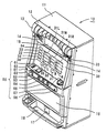
【図2】本実施形態のスロットマシンの前面扉を開いた状態の斜視図である。
【図3】図2の矢印線Aに沿ってスロットマシン10の本体11右下部を内側から見たときの部分説明図である。
【図4】スロットマシンをメダル回収装置を備えない遊技場に設置したときの状態の一例を示す説明図である。
【図5】スロットマシンをメダル回収装置を備える遊技場に設置したときの状態の一例を示す説明図である。
【図6】スロットマシンをメダル回収装置を備える遊技場に設置したときの状態の一例を示す説明図である。
【図7】変形例のメダル回収装置98Bの概略の構成を示す説明図である。
【図8】変形例のメダル回収装置98Bを備えるスロットマシンをメダル回収装置を備える遊技場に設置したときの状態の一例を示す説明図である。
【符号の説明】
10…スロットマシン、11…本体、12…前面扉、13…上部ランプ、14…スピーカ、15…上段表示パネル、16…下段表示パネル、17…メダル払出口、18…メダル受け皿、20…施錠装置、30…中断表示パネル、31L,31M,31R…露出窓、32…1枚ベットランプ、33…2枚ベットランプ、34…3枚ベットランプ、35…クレジット枚数表示部、36…ゲーム数表示部、37…払出枚数表示部、50…操作部、51…クレジットボタン、52…スタートレバー、52a…スタートスイッチ、53…左回胴用ストップボタン、54…中回胴用ストップボタン、55…右回胴用ストップボタン、56…返却ボタン、57…メダル投入口、61…1枚ベットボタン、62…2枚ベットボタン、63…マックスベットボタン、64…排出シュート、70…制御装置、81…電源スイッチ、82…リセットスイッチ、83…設定キー挿入孔、85…電源ボックス、86…ホッパ、87…補助タンク、88…払出装置、92…払出用通路、93…開口、95…筐体、97…貫通孔、98,98B…メダル回収箱、99,199a,199b…底板、100…排出口形成部、101a,101b…凸部、102…溝、103…センサ棒、105…排出口、110…メダル回収装置、150…固定凸部、151a,151b…取付凸部、160a…固定貫通孔、160b…取付固定部、161a,161b…取付貫通孔、171a,171b…傾斜形成部、L…左回胴、M…中回胴、R…右回胴。[0001]
BACKGROUND OF THE INVENTION
The present invention relates to a gaming machine.
[0002]
[Prior art]
Conventionally, as this type of gaming machine, a collection box for collecting medals overflowing from the hopper when the medals stored in the hopper for storing and paying out medals exceeds a predetermined amount is installed inside. Slot machines have been proposed. In such a slot machine, when installing in a game hall that does not have a collection device that automatically collects overflowing medals, the medals are manually placed in a collection box installed inside the slot machine based on a sensor that checks the fullness of medals. Collected. When the game machine is provided with a collecting device that automatically collects overflowing medals, a medal is collected by attaching a communication member connected to a discharge port for discharging the medals to the outside inside the slot machine.
[0003]
[Problems to be solved by the invention]
However, in such a slot machine, it is necessary to prepare either a collection box or a connecting member according to the game hall to be installed. When installing a slot machine in a game hall that does not have a collection device, it is necessary to prepare a collection box for manually collecting medals. When installing in a game hall that has a collection device, the medals overflowing from the hopper It is necessary to prepare a communication member for discharging to the outside. Further, when installing the connecting member, an installation work for fixing the connecting member inside the slot machine is also required.
[0004]
An object of the gaming machine of the present invention is to provide a gaming machine that does not need to always have both a collection box and a communication member regardless of the installation location.
[0005]
[Means for solving the problems and their functions and effects]
The gaming machine of the present invention employs the following means in order to achieve the above-described object.
[0006]
Means 1. The gaming machine of the present invention is
A gaming machine that plays a game as a game medium is inserted,
A medium storage section for storing the input game medium;
A housing having a through-hole formed in a size that allows passage of the game medium in at least a part of the lower portion, and detachably attached above or below the through-hole of the housing. A collection box for collecting the game medium overflowing from the medium storage unit, comprising an obstruction member that obstructs the passage of the game medium;
The gist is to provide the inside.
[0007]
In the gaming machine of the present invention, the recovery box for recovering the game medium overflowing from the medium storage portion is formed from a housing having a through hole formed in a size that allows the game medium to pass through at least a part of the lower part. An inhibiting member that is detachably attached above or below the through hole of the housing and that blocks the passage of the game medium in the through hole can be separated. That is, the recovery box functions as a recovery box for storing the game medium when the obstruction member is attached to the housing, and the game medium is discharged to the outside of the gaming machine at a position where the obstruction member is removed and substantially aligned with the through hole. When the discharge port is formed, it functions as a guide member that guides the game medium to the discharge port. Therefore, it is not necessary to prepare both the collection box and the communication member.
[0008]
Mean 2. The gaming machine according to means 1, wherein the casing has the through-hole formed in at least a part of a bottom portion thereof, and the inhibition member is formed as a plate member having substantially the same shape as the bottom portion of the casing. A gaming machine that is detachably attached to the bottom of the housing from above the through hole. If it carries out like this, an obstruction member can be attached to a bottom part of a case only by pulling from the upper part.
[0009]
Means 3. The gaming machine according to means 1 or 2, wherein the blocking member is constituted by a plurality of members. In this way, the inhibition member can be partially attached and detached, so that the size of the inhibition portion of the through hole can be adjusted.
[0010]
Means 4. 4. The gaming machine according to any one of means 1 to 3, wherein the housing is formed with an attachment fixing portion for attaching and fixing the inhibition member by the elasticity of the housing or the elasticity of the inhibition member. In this way, the inhibiting member can be fixed to the housing.
[0011]
Means 5. 5. The gaming machine according to any one of means 1 to 4, wherein the recovery box includes a guide member that guides game media overflowing from the medium storage portion to the through hole when the inhibition member is removed. If it carries out like this, a game medium can be guide | induced to a through-hole.
[0012]
Means 6. 6. A gaming machine according to means 5, wherein the blocking member is a member that functions as the guiding member. In this way, the inhibiting member can be used as the guiding member.
[0013]
Mean 7 The gaming machine according to means 6, wherein the obstructing member is a member that functions as the guiding member when attached so as to have a predetermined angle from the bottom to the side of the casing. If it carries out like this, a game medium can be guide | induced to a through-hole more reliably.
[0014]
Means 8. 8. The gaming machine according to claim 7, wherein a bottom portion of the housing is formed with a positioning portion that determines an attachment position of the inhibition member when the inhibition member is attached to have a predetermined angle. If it carries out like this, the attachment position of the obstruction member can be determined easily.
[0015]
Means 9. The gaming machine according to claim 8, wherein the positioning portion is formed so that the blocking member can be attached to a plurality of positions. If it carries out like this, an obstruction member can be attached to a desired position.
[0016]
[0017]
[0018]
[0019]
[0020]
[0021]
Means 15. A gaming machine according to any one of means 1 to 12, wherein the gaming machine is a fusion of a pachinko machine and a slot machine. The basic configuration of a gaming machine in which a pachinko machine and a slot machine as such a gaming machine are fused is as follows: “After variably displaying an identification element string composed of a plurality of identification elements for identifying the gaming state according to the gaming state Display means for confirming and displaying the identification element, and the variation of the identification element is started due to the operation of the start operation means (for example, the operation lever), or due to the operation of the stop operation means (for example, the stop button) or Special game state generating means for generating a special game state advantageous to the player on the condition that the change of the identification element is stopped after a predetermined time has elapsed and the confirmed identification element at the time of the stop is a specific identification element; In addition, a game ball is used as a game medium, and a predetermined number of game balls are required at the start of variation of the identification element. Can be mentioned gaming machine "made is configured to the game balls are paid out. Such gaming machines include a special game state (big hit state) that is advantageous to a player who can acquire at least a large number of game balls, and a normal game state that is disadvantageous to a player who consumes game balls. There may be different types of gaming states. Here, the “game medium” corresponds to a game ball when using a game ball, and a coin or medal when using a coin or medal.
[0022]
As described in the
[0023]
A collection box for collecting gaming media that is arranged inside a gaming machine that plays a game as the gaming media is thrown in and overflows from the medium storage unit that stores the gaming media that has been thrown in,
A housing having a through hole formed in a size that allows passage of the game medium in at least a part of the lower portion;
An inhibiting member that is detachably attached above or below the through hole of the housing and inhibits passage of the game medium in the through hole;
It is a summary to provide.
[0024]
The collection box of the present invention is attached to a housing having a through hole formed in a size that allows game media to pass through at least a part of the lower portion thereof, and is detachably attached above or below the through hole of the housing. It is comprised from two types of members with the obstruction member which inhibits passage of the game medium in a through-hole. For this reason, when the obstruction member is attached to the housing, it functions as a collection box for storing the game medium, and removes the obstruction member and discharges the game medium to the outside of the gaming machine at a position substantially aligned with the through hole. When is formed, it functions as a guide member that guides the game medium to the discharge port. Therefore, it is not necessary to prepare both the collection box and the communication member.
[0025]
[0026]
[0027]
Means 19. 19. A collection box according to any one of
[0028]
[0029]
Means 21. The collection box according to means 20, wherein the inhibition member is a member that functions as the guide member when attached so as to have a predetermined angle from the bottom to the side of the casing. If it carries out like this, a game medium can be guide | induced to a through-hole more reliably.
[0030]
Means 22. The collection box according to means 21, wherein a bottom portion of the casing is formed with a positioning portion that determines a mounting position of the inhibition member when the inhibition member is attached to have a predetermined angle. If it carries out like this, the attachment position of the obstruction member can be determined easily.
[0031]
Means 23. The collection box according to means 22, wherein the positioning part is formed so that the blocking member can be attached to a plurality of positions. If it carries out like this, an obstruction member can be attached to a desired position.
[0032]
Means 24. The collection box according to
[0033]
Means 25. 25. The collection box according to means 24, wherein the two plate members are attached so as to have a predetermined angle from the approximate center of the bottom of the housing toward the side surface. If it carries out like this, when one board member is removed, the other can be functioned as a guide member which guides a game medium to a penetration hole of a recovery box more certainly.
[0034]
DETAILED DESCRIPTION OF THE INVENTION
Next, embodiments of the present invention will be described using examples. FIG. 1 is a perspective view of a
[0035]
FIG. 3 is a partial explanatory view when the lower right portion of the
[0036]
On the inner side of the lower right portion of the
[0037]
FIG. 4 is an explanatory diagram showing an example of a state when the
[0038]
FIG. 5 and FIG. 6 are explanatory views showing an example of a state when the
[0039]
According to the
[0040]
In the
[0041]
In the
[0042]
In the
[0043]
In the
[0044]
In the embodiment, the slot machine is described as an example of the form of the present invention. However, the gaming machine to which the present invention is applicable is not limited to the slot machine. Of course, the present invention can also be applied to all gaming machines that perform payout, such as a pachinko machine or a gaming machine in which a pachinko machine and a slot machine are combined. As a basic configuration of this slot machine, it is provided with a display means for confirming and displaying an identification element after variably displaying an identification element string composed of a plurality of identification elements for identifying the gaming state according to the gaming state. The variation of the identification element is started due to the operation of the operation means (for example, the operation lever), and the variation of the identification element is stopped due to the operation of the operation means for the stop (for example, the stop button) or when a predetermined time elapses. And a special gaming state generating means for generating a special gaming state advantageous to the player on the condition that the definite identification element at the time of stoppage is a specific identification element. In this case, examples of the game medium include coins and medals. In such a slot machine, at least a large number of game media such as coins, medals, etc., a special game state (big hit state) that is advantageous to a player and a player who consumes game media are disadvantageous. There may be a normal gaming state. In addition, the basic configuration of the pachinko machine is provided with an operation handle, and in response to the operation of the handle, a game ball is fired into a predetermined game area, and the game ball wins an operating port arranged at a predetermined position in the game area. As a necessary condition, the display means starts to display the variation of the identification element. In addition, when the special game state is generated, the winning opening arranged at a predetermined position in the game area is opened in a predetermined mode and the game ball Can be awarded, and a valuable value (including writing to a magnetic card as well as a prize ball) according to the number of prizes is given. These pachinko machines have a special game state (big hit state) that is advantageous to a player who can acquire at least several other game balls, and a normal game that is disadvantageous to a player who consumes game balls. State may exist. Here, the “game medium” corresponds to a game ball. Furthermore, the basic configuration of a gaming machine that is a combination of a pachinko machine and a slot machine is “the identification element after variably displaying an identification element string composed of a plurality of identification elements for identifying the gaming state according to the gaming state. Display means for confirming and displaying, the change of the identification element is started due to the operation of the start operation means (for example, the operation lever), and due to the operation of the stop operation means (for example, the stop button) or for a predetermined time Special game state generating means for generating a special game state advantageous to the player on the condition that the change of the identification element is stopped as time passes, and the confirmed identification element at the time of the stop is a specific identification element, A game ball is used as a game medium, and a predetermined number of game balls are required at the start of variation of the identification element, and many game balls are generated when a special game state occurs. Can be mentioned gaming machine "made is configured to be paid out. Such gaming machines include a special game state (big hit state) that is advantageous to a player who can acquire at least a large number of game balls, and a normal game state that is disadvantageous to a player who consumes game balls. There may be different types of gaming states. Here, the “game medium” corresponds to a game ball when using a game ball, and a coin or medal when using a coin or medal.
[0045]
The embodiments of the present invention have been described using the embodiments. However, the present invention is not limited to these embodiments, and can be implemented in various forms without departing from the gist of the present invention. Of course you get.
[Brief description of the drawings]
FIG. 1 is a perspective view showing a state in which a front door of the slot machine of the present embodiment is closed.
FIG. 2 is a perspective view showing a state in which a front door of the slot machine of the present embodiment is opened.
3 is a partial explanatory view of the lower right portion of the
FIG. 4 is an explanatory diagram showing an example of a state when the slot machine is installed in a game arcade that does not include a medal recovery device.
FIG. 5 is an explanatory diagram showing an example of a state when the slot machine is installed in a game arcade equipped with a medal recovery device.
FIG. 6 is an explanatory diagram showing an example of a state when the slot machine is installed in a game arcade equipped with a medal recovery device.
FIG. 7 is an explanatory diagram showing a schematic configuration of a
FIG. 8 is an explanatory diagram showing an example of a state when a slot machine including a
[Explanation of symbols]
DESCRIPTION OF
Claims (2)
前記投入された遊技用媒体を貯留する媒体貯留部と、
下部の少なくとも一部に前記遊技用媒体の通過が可能な大きさに形成された貫通孔を有する筐体と該筐体の前記貫通孔より上方に着脱可能に取り付けられ前記貫通孔における前記遊技用媒体の通過を阻害する阻害部材とからなり、前記媒体貯留部からあふれる遊技用媒体を回収する回収箱と、
を内部に備え、
前記回収箱は、前記阻害部材を取り外したときに前記媒体貯留部からあふれる遊技用媒体を前記貫通孔に誘導する誘導部材を備え、
前記阻害部材は、前記筐体の底部から側面に向けて所定の角度を有するよう取り付けたとき、前記誘導部材として機能する部材であり、
前記筐体の底部は、前記阻害部材を所定の角度を有するよう取り付けたときに該阻害部材の取り付け位置を決める位置決め部が形成されてなる
遊技機。A gaming machine that plays a game as a game medium is inserted,
A medium storage section for storing the input game medium;
The game in the lower part of at least some said detachably attached to the upper side than the through hole of the housing and the housing having a through hole which is formed in a size capable of passing of the game medium to the through-hole A collection box that collects the game medium overflowing from the medium storage unit, and an obstruction member that obstructs the passage of the medium.
Equipped with an internal,
The collection box includes a guide member that guides the game medium overflowing from the medium storage portion to the through hole when the inhibition member is removed,
The obstruction member is a member that functions as the guide member when attached so as to have a predetermined angle from the bottom of the housing toward the side surface;
A gaming machine in which a bottom portion of the casing is formed with a positioning portion that determines a mounting position of the inhibition member when the inhibition member is attached to have a predetermined angle .
下部の少なくとも一部に前記遊技用媒体の通過が可能な大きさに形成された貫通孔を有する筐体と、
該筐体の前記貫通孔より上方に着脱可能に取り付けられたときには前記貫通孔における前記遊技用媒体の通過を阻害する部材として機能し、前記貫通孔から取り外したときには前記媒体貯留部からあふれる遊技用媒体を前記貫通孔に誘導する誘導部材として機能する阻害部材と、
を備え、
前記阻害部材は、前記筐体の底部から側面に向けて所定の角度を有するよう取り付けたとき、前記誘導部材として機能する部材であり、
前記筐体の底部は、前記阻害部材を所定の角度を有するよう取り付けたときに該阻害部材の取り付け位置を決める位置決め部が形成されてなる
回収箱。A collection box for collecting gaming media that is arranged inside a gaming machine that plays a game as the gaming media is thrown in and overflows from the medium storage unit that stores the gaming media that has been thrown in,
A housing having a through hole formed in a size that allows passage of the game medium in at least a part of the lower portion;
When mounted detachably on the upper side than the through hole of the housing serves as a member for inhibiting the passage of the game medium in the through hole, a game overflowing from the medium reservoir when removed from the through hole An inhibiting member that functions as a guiding member that guides the working medium to the through hole;
Equipped with a,
The obstruction member is a member that functions as the guide member when attached so as to have a predetermined angle from the bottom of the housing toward the side surface;
The bottom of the housing is a collection box formed with a positioning portion that determines the attachment position of the inhibition member when the inhibition member is attached to have a predetermined angle .
Priority Applications (1)
| Application Number | Priority Date | Filing Date | Title |
|---|---|---|---|
| JP2002008314A JP4151270B2 (en) | 2002-01-17 | 2002-01-17 | Game machine |
Applications Claiming Priority (1)
| Application Number | Priority Date | Filing Date | Title |
|---|---|---|---|
| JP2002008314A JP4151270B2 (en) | 2002-01-17 | 2002-01-17 | Game machine |
Related Child Applications (1)
| Application Number | Title | Priority Date | Filing Date |
|---|---|---|---|
| JP2008121463A Division JP4894813B2 (en) | 2008-05-07 | 2008-05-07 | Amusement machines and collection boxes |
Publications (3)
| Publication Number | Publication Date |
|---|---|
| JP2003205069A JP2003205069A (en) | 2003-07-22 |
| JP2003205069A5 JP2003205069A5 (en) | 2005-08-11 |
| JP4151270B2 true JP4151270B2 (en) | 2008-09-17 |
Family
ID=27646612
Family Applications (1)
| Application Number | Title | Priority Date | Filing Date |
|---|---|---|---|
| JP2002008314A Expired - Lifetime JP4151270B2 (en) | 2002-01-17 | 2002-01-17 | Game machine |
Country Status (1)
| Country | Link |
|---|---|
| JP (1) | JP4151270B2 (en) |
Families Citing this family (13)
| Publication number | Priority date | Publication date | Assignee | Title |
|---|---|---|---|---|
| JP2005040572A (en) * | 2003-10-29 | 2005-02-17 | Oizumi Corp | Recovery tank for game machine |
| JP4693000B2 (en) * | 2006-07-03 | 2011-06-01 | 株式会社オリンピア | Amusement media receiving box and gaming machine |
| JP2008301864A (en) * | 2007-06-05 | 2008-12-18 | Samii Kk | Game machine |
| JP5007197B2 (en) * | 2007-10-25 | 2012-08-22 | 株式会社ニューギン | Reserving device for game media |
| JP5090205B2 (en) * | 2008-02-21 | 2012-12-05 | 株式会社オリンピア | Overflow tank |
| JP5350657B2 (en) * | 2008-03-24 | 2013-11-27 | 高砂電器産業株式会社 | Slot machine |
| JP4976355B2 (en) * | 2008-09-19 | 2012-07-18 | 株式会社大都技研 | Amusement stand |
| JP4929266B2 (en) * | 2008-10-15 | 2012-05-09 | 株式会社大都技研 | Amusement stand |
| JP5584244B2 (en) * | 2012-03-14 | 2014-09-03 | 株式会社ユニバーサルエンターテインメント | Game machine |
| JP5497141B2 (en) * | 2012-12-12 | 2014-05-21 | 株式会社ユニバーサルエンターテインメント | Game machine |
| JP5922714B2 (en) * | 2014-07-03 | 2016-05-24 | 株式会社ユニバーサルエンターテインメント | Game machine |
| JP6106785B2 (en) * | 2016-04-14 | 2017-04-05 | 株式会社ユニバーサルエンターテインメント | Game machine |
| JP6177980B2 (en) * | 2016-09-26 | 2017-08-09 | 株式会社ユニバーサルエンターテインメント | Game machine |
-
2002
- 2002-01-17 JP JP2002008314A patent/JP4151270B2/en not_active Expired - Lifetime
Also Published As
| Publication number | Publication date |
|---|---|
| JP2003205069A (en) | 2003-07-22 |
Similar Documents
| Publication | Publication Date | Title |
|---|---|---|
| JP4151270B2 (en) | Game machine | |
| JP2945443B2 (en) | Ball game machine | |
| JP4858571B2 (en) | Game machine | |
| JP4894813B2 (en) | Amusement machines and collection boxes | |
| JP5370442B2 (en) | Game machine | |
| JP4174991B2 (en) | Game machine | |
| JP4131545B2 (en) | Slot machine | |
| JP2003236047A (en) | Game machine | |
| JP4706717B2 (en) | Game machine | |
| JP4131548B2 (en) | Slot machine | |
| JP4151266B2 (en) | Game machine | |
| JP2010029251A (en) | Game machine | |
| JP2003236046A (en) | Game machine | |
| JP4916865B2 (en) | Game machine | |
| JP3731587B2 (en) | Method of attaching medium guide member to machine body of game machine and medium guide member and mounting bracket used in the method | |
| JP5228196B2 (en) | Game equipment | |
| JP2016123827A (en) | Pinball game machine | |
| JP4261780B2 (en) | Pachinko machine | |
| JP4575850B2 (en) | Game machine | |
| JP5099313B2 (en) | Game machine | |
| JP2009172437A (en) | Game machine | |
| JP5099671B2 (en) | Game machine | |
| JP4895770B2 (en) | Game machine | |
| JP5130559B2 (en) | Game machine | |
| JP2962478B1 (en) | Pachinko machine |
Legal Events
| Date | Code | Title | Description |
|---|---|---|---|
| A521 | Request for written amendment filed |
Free format text: JAPANESE INTERMEDIATE CODE: A523 Effective date: 20050114 |
|
| A621 | Written request for application examination |
Free format text: JAPANESE INTERMEDIATE CODE: A621 Effective date: 20050114 |
|
| A977 | Report on retrieval |
Free format text: JAPANESE INTERMEDIATE CODE: A971007 Effective date: 20080314 |
|
| A131 | Notification of reasons for refusal |
Free format text: JAPANESE INTERMEDIATE CODE: A131 Effective date: 20080318 |
|
| A521 | Request for written amendment filed |
Free format text: JAPANESE INTERMEDIATE CODE: A523 Effective date: 20080515 |
|
| TRDD | Decision of grant or rejection written | ||
| A01 | Written decision to grant a patent or to grant a registration (utility model) |
Free format text: JAPANESE INTERMEDIATE CODE: A01 Effective date: 20080610 |
|
| A01 | Written decision to grant a patent or to grant a registration (utility model) |
Free format text: JAPANESE INTERMEDIATE CODE: A01 |
|
| A61 | First payment of annual fees (during grant procedure) |
Free format text: JAPANESE INTERMEDIATE CODE: A61 Effective date: 20080623 |
|
| R150 | Certificate of patent or registration of utility model |
Ref document number: 4151270 Country of ref document: JP Free format text: JAPANESE INTERMEDIATE CODE: R150 Free format text: JAPANESE INTERMEDIATE CODE: R150 |
|
| FPAY | Renewal fee payment (event date is renewal date of database) |
Free format text: PAYMENT UNTIL: 20110711 Year of fee payment: 3 |
|
| FPAY | Renewal fee payment (event date is renewal date of database) |
Free format text: PAYMENT UNTIL: 20110711 Year of fee payment: 3 |
|
| FPAY | Renewal fee payment (event date is renewal date of database) |
Free format text: PAYMENT UNTIL: 20140711 Year of fee payment: 6 |
|
| R250 | Receipt of annual fees |
Free format text: JAPANESE INTERMEDIATE CODE: R250 |
|
| R250 | Receipt of annual fees |
Free format text: JAPANESE INTERMEDIATE CODE: R250 |
|
| R250 | Receipt of annual fees |
Free format text: JAPANESE INTERMEDIATE CODE: R250 |
|
| R250 | Receipt of annual fees |
Free format text: JAPANESE INTERMEDIATE CODE: R250 |
|
| R250 | Receipt of annual fees |
Free format text: JAPANESE INTERMEDIATE CODE: R250 |
|
| R250 | Receipt of annual fees |
Free format text: JAPANESE INTERMEDIATE CODE: R250 |
|
| R250 | Receipt of annual fees |
Free format text: JAPANESE INTERMEDIATE CODE: R250 |
|
| R250 | Receipt of annual fees |
Free format text: JAPANESE INTERMEDIATE CODE: R250 |
|
| R250 | Receipt of annual fees |
Free format text: JAPANESE INTERMEDIATE CODE: R250 |
|
| EXPY | Cancellation because of completion of term |