JP4148472B2 - crank - Google Patents
crank Download PDFInfo
- Publication number
- JP4148472B2 JP4148472B2 JP2003565791A JP2003565791A JP4148472B2 JP 4148472 B2 JP4148472 B2 JP 4148472B2 JP 2003565791 A JP2003565791 A JP 2003565791A JP 2003565791 A JP2003565791 A JP 2003565791A JP 4148472 B2 JP4148472 B2 JP 4148472B2
- Authority
- JP
- Japan
- Prior art keywords
- crank
- wiper
- wiper mechanism
- length
- sweep
- Prior art date
- Legal status (The legal status is an assumption and is not a legal conclusion. Google has not performed a legal analysis and makes no representation as to the accuracy of the status listed.)
- Expired - Fee Related
Links
Images


Classifications
-
- B—PERFORMING OPERATIONS; TRANSPORTING
- B60—VEHICLES IN GENERAL
- B60S—SERVICING, CLEANING, REPAIRING, SUPPORTING, LIFTING, OR MANOEUVRING OF VEHICLES, NOT OTHERWISE PROVIDED FOR
- B60S1/00—Cleaning of vehicles
- B60S1/02—Cleaning windscreens, windows or optical devices
- B60S1/04—Wipers or the like, e.g. scrapers
- B60S1/06—Wipers or the like, e.g. scrapers characterised by the drive
- B60S1/16—Means for transmitting drive
- B60S1/18—Means for transmitting drive mechanically
- B60S1/24—Means for transmitting drive mechanically by rotary cranks
-
- Y—GENERAL TAGGING OF NEW TECHNOLOGICAL DEVELOPMENTS; GENERAL TAGGING OF CROSS-SECTIONAL TECHNOLOGIES SPANNING OVER SEVERAL SECTIONS OF THE IPC; TECHNICAL SUBJECTS COVERED BY FORMER USPC CROSS-REFERENCE ART COLLECTIONS [XRACs] AND DIGESTS
- Y10—TECHNICAL SUBJECTS COVERED BY FORMER USPC
- Y10T—TECHNICAL SUBJECTS COVERED BY FORMER US CLASSIFICATION
- Y10T74/00—Machine element or mechanism
- Y10T74/18—Mechanical movements
- Y10T74/18056—Rotary to or from reciprocating or oscillating
- Y10T74/18184—Crank, pitman, and lever
Landscapes
- Engineering & Computer Science (AREA)
- Mechanical Engineering (AREA)
- Transmission Devices (AREA)
- Sampling And Sample Adjustment (AREA)
Abstract
Description
本発明はクランクに関し、より詳細には、リンクとクランクとを備えるタイプの自動車のワイパ機構の掃引行程を調整することがきるクランクに関する。The present invention relates to a crank, and more particularly to a crank capable of adjusting a sweep stroke of a wiper mechanism of an automobile of a type including a link and a crank.
このタイプのワイパ機構におけるクランクは、ほぼ水平な方向に延びる長手の本体を有する。また、このクランクの本体は、第1の端部において垂直軸の回りを回動し、かつリンク上に位置する第2の端部においても回動するようになっている。さらに、このタイプのワイパ機構は、クランクの回動に係る第1の端部と第2の端部との間の距離を加減することによって、掃引行程を調整しうるタイプのものである。 The crank in this type of wiper mechanism has a longitudinal body extending in a generally horizontal direction. The main body of the crank rotates around the vertical axis at the first end, and also rotates at the second end located on the link. Further, this type of wiper mechanism is of a type that can adjust the sweep stroke by adjusting the distance between the first end and the second end related to the rotation of the crank.
上述のような、1つまたは複数のリンクと、1つまたは複数のクランクとを具備する回動システムは、例えば、モータ(通常は、ギヤボックスと関連づけられている)が、ワイパ用ドライブシャフトに固定された少なくとも1つのワイパを交互に掃引するようになっている駆動装置において採用されている。なお、ワイパ用ドライブシャフトは、自動車に対して回転可能に取り付けられている。 As described above, a pivoting system comprising one or more links and one or more cranks, for example, includes a motor (usually associated with a gearbox) on a wiper drive shaft. It is employed in a drive device that is adapted to alternately sweep at least one fixed wiper. The wiper drive shaft is rotatably attached to the automobile.
リンクとクランクとからなるワイパ機構を用いて、モータの出力シャフトの連続的な回転運動を、各ワイパ用ドライブシャフトを交互に回動させる運動に変換することができる。 By using a wiper mechanism including a link and a crank, it is possible to convert a continuous rotational motion of the output shaft of the motor into a motion that alternately rotates the drive shafts for each wiper.
各ワイパの掃引行程を決定するのは、ワイパ機構の立体構成と動力学、特にクランクの長さである。ワイパ機構の立体構成を変化させることにより、モータの出力シャフトのただ1つの運動から、2つのワイパに、互いに異なる掃引角運動を行わせることができる。 It is the configuration and dynamics of the wiper mechanism, in particular the length of the crank, that determines the sweep stroke of each wiper. By changing the three-dimensional configuration of the wiper mechanism, it is possible to cause the two wipers to perform different sweep angular movements from only one movement of the output shaft of the motor.
したがって、ワイパ機構の立体構成、特にスイベルを介して互いに回動するリンクとクランクの長さと、ワイパ機構における種々の構成要素の相互位置関係を、正確に制御しうることが、特に重要である。 Therefore, it is particularly important that the three-dimensional configuration of the wiper mechanism, particularly the length of the link and the crank that rotate relative to each other via the swivel, and the mutual positional relationship of various components in the wiper mechanism can be accurately controlled.
しかし、ワイパ機構における種々の構成要素の大きさは、各ワイパ機構ごとに不均一な場合があり、そのため、ワイパの掃引行程が満足しうるものにならないことがある。 However, the size of the various components in the wiper mechanism may not be uniform for each wiper mechanism, and therefore the wiper sweep stroke may not be satisfactory.
そこで、ワイパ機構におけるクランクの長さを、クランクにおけるスイベルの位置を調節することによって、「変化」させることが提案されている(特許文献1参照)。 Therefore, it has been proposed to “change” the length of the crank in the wiper mechanism by adjusting the position of the swivel in the crank (see Patent Document 1).
この目的のため、スイベルは、調節孔となる長円形の孔を介して固定されており、クランクの長さは、スイベルの固定具の位置によって定まる。この場合、クランクの長さが経時的に変化するか否かは、取付けシステムの信頼性に関連する。 For this purpose, the swivel is fixed through an oval hole serving as an adjustment hole, and the crank length is determined by the position of the swivel fixture. In this case, whether the crank length changes over time is related to the reliability of the mounting system.
この外、クランクにおけるスイベルの位置を、垂直軸の回りで調節しながら移動させうる中間調節片によって調節することが提案されている(特許文献2または特許文献3参照)。 In addition, it has been proposed to adjust the position of the swivel on the crank by an intermediate adjustment piece that can be moved while adjusting around the vertical axis (see Patent Document 2 or Patent Document 3).
スイベルは、この中間調節片に取り付けられており、クランクは、中間調節片に取り付けられているが、このとき、スイベルの軸と、中間調節片の垂直軸とは、互いにずれるようにして、位置設定される。スイベルの位置は、中間調節片の角度位置を変化させることによって調節される。 The swivel is attached to the intermediate adjustment piece, and the crank is attached to the intermediate adjustment piece. At this time, the swivel shaft and the vertical axis of the intermediate adjustment piece are displaced from each other. Is set. The position of the swivel is adjusted by changing the angular position of the intermediate adjustment piece.
しかし、現在までに提案されている種々の連結装置は、製造するのにあまりにも複雑であるか、または長円形の孔におけるスイベルの正確な位置を、時間が経過しても変わらないように維持することに関しては、信頼性が十分でないことが明らかになっている。
本発明の目的は、ワイパ機構に対して経時的に伝達される力や振動に抗して、スイベルの正確な位置を保つことができる、簡単で、かつ信頼性の高い調整手段を提供することである。 An object of the present invention is to provide a simple and highly reliable adjustment means that can maintain an accurate position of a swivel against a force or vibration transmitted to a wiper mechanism over time. It is.
本発明は、上記の目的を実現するために、上述のようなタイプのワイパ機構において、クランク本体の軸方向部分の長さを加減する調節過程を含む、ワイパ機構の掃引行程を調整する方法を提供するものである。 In order to achieve the above object, the present invention provides a method for adjusting the sweep stroke of a wiper mechanism, including an adjustment process for adjusting the length of an axial portion of a crank body in a wiper mechanism of the type described above. It is to provide.
本発明を、次のような特徴を有するものとすることができる。
−調節過程は、クランク本体の軸方向部分の少なくとも一部を恒久的に変形させる過程を含む。
−調節過程は、クランク本体の回動可能な両端部を軸方向に引き寄せることによって、クランク本体の軸方向部分の長さを短縮する過程を含む。
−調節過程は、ワイパ機構を試験台に取り付ける過程の後に行われる。
The present invention may have the following characteristics.
The adjusting process includes a process of permanently deforming at least part of the axial part of the crank body;
The adjusting process includes a process of shortening the length of the axial part of the crank body by pulling the pivotable ends of the crank body in the axial direction;
The adjustment process takes place after the process of attaching the wiper mechanism to the test bench.
本発明はまた、自動車のワイパ機構の変位伝達用連結装置に属するクランクであって、水平面上で軸方向に延びる本体を有し、前記連結装置におけるリンク上で回動する第2の端部と、ワイパアームに連結され、垂直軸の回りを回動しうるようになっている第1の端部とを有し、かつ前記回動可能なクランクの両端部間の距離が調節可能となっているクランクにおいて、このクランクの本体は、前記クランクの両端部間の距離を調節するために、恒久的に変形しうる少なくとも1つの軸方向部分を有することを特徴とするクランクを提供することも目的としている。 The present invention also relates to a crank that belongs to a displacement transmission connecting device of an automobile wiper mechanism, and has a main body extending in an axial direction on a horizontal plane, and a second end that rotates on a link in the connecting device; A first end coupled to the wiper arm and adapted to pivot about a vertical axis, and the distance between both ends of the pivotable crank being adjustable. It is also an object of the present invention to provide a crank, characterized in that the crank body has at least one axial part that can be permanently deformed in order to adjust the distance between the ends of the crank. Yes.
クランクに関する本発明における他の特徴は、クランクの本体が、軸方向を向く2つの対向する変形可能な分枝部を区画するための全体として軸方向を向く少なくとも1つの長円孔を有することである。 Another feature of the invention relating to the crank is that the body of the crank has at least one oblong hole that faces generally axially to define two opposing deformable branches that point axially. is there.
本発明によれば、ワイパ機構に対して経時的に伝達される力や振動に抗して、スイベルの正確な位置を保つことができる、簡単で、かつ信頼性の優れた調整方法が提供される。 According to the present invention, there is provided a simple and highly reliable adjustment method capable of maintaining the accurate position of the swivel against the force and vibration transmitted to the wiper mechanism over time. The
本発明の他の特徴および効果は、添付図面を参照して行う以下の詳細な説明から明らかになると思う。 Other features and advantages of the present invention will become apparent from the following detailed description, which proceeds with reference to the accompanying drawings.
以下においては、本発明を限定する意味ではなく、垂直方向、軸方向、および横断方向なる語を用いるが、これらの方向は、図2aにおいて、それぞれ符号V、L、およびTを用いて示してある。 In the following, the terms vertical, axial and transverse are used, not meant to limit the invention, but these directions are indicated in FIG. 2a using the symbols V, L and T, respectively. is there.
以下の説明において、複数の図にまたがる同一または類似の構成要素には、同一の符号を付してある。 In the following description, the same reference numerals are given to the same or similar components extending over a plurality of drawings.
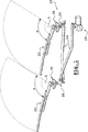
図1は、2つのワイパブレード22が備え付けられている自動車のフロントガラス(図示せず)の公知のワイパ機構20を示す。各ワイパブレード22は、ほぼ垂直な軸Aの回りを回動することができる。ワイパ機構20は、リンク24とクランク26とからなる連結装置を備えている。リンク24とクランク26は、ワイパブレード22を、ワイパ機構20を駆動する歯車付きモータ28に連結している。
FIG. 1 shows a known
図2a〜図2cにも示すように、公知の方法によれば、各クランク26は、水平面上を軸方向に延びるほぼ平坦な本体30を有する。本体30は、第1の端部30aにおいて、ワイパブレード22の垂直な回転軸Aの回りを回動する。
As shown also in FIGS. 2a-2c, according to known methods, each
本体30は、第2の端部(自由端)30bにおいて、リンク24とクランク26とを連結するスイベル32を備えている。
The
各ワイパブレード22は、ワイパ用ドライブシャフト36の回転軸Aの回りで、交互に回動式の掃引運動を行うように、ワイパ用ドライブシャフト36の例えば上端部34に取り付けられている。ワイパ用ドライブシャフト36は、ベアリング38(図1参照)によって案内される。ベアリング38は、ワイパ用ドライブシャフト36の上端部34だけが突出するようになっている自動車のボディ(図示せず)の内側において、ワイパが設置されるフロントガラスに近接して配置されている。
Each
図2a〜図2cに示すように、回転軸Aの回りで、ワイパブレード22に回動式の掃引運動を行わせるため、ワイパ用ドライブシャフト36は、クランク26の本体30における第1の端部30aから、上向きに延びている。
2a-2c, the
本発明によれば、図2aに示すように、クランク26の本体30は、ワイパブレード22の掃引行程αを加減する目的で、クランク26における本体30の2つの端部30aと30bの間の距離Dを調整するために、恒久的に変形させることができる少なくとも1つの軸方向部分40を有する。
According to the present invention, as shown in FIG. 2a, the
そのため、本体30の軸方向部分40の中央に、軸方向を向く長円孔42を設けておくのが好ましい。長円孔42は、本体30において、軸方向に延びる2つの分枝部44,44を区画している。本発明の好ましい実施形態によれば、長円孔42は、2つの分枝部44,44が、クランク26の中央の軸に関して対称となるように、その位置と大きさが定められている。
Therefore, it is preferable to provide an
長円孔42の大きさ、および本体30の軸方向部分40の大きさは、クランク26の本体30における2つの端部30aと30bの間の距離を調整するために、分枝部44を変形させうるようなものとされる。しかし、分枝部44は、ワイパ機構20が作動しているときには、変形してはならない。
The size of the
本発明はまた、ワイパ機構20における各ワイパブレード22の掃引行程αを調整する方法を提供するものである。この目的のため、ワイパ機構20は、最初に、各ワイパブレードの予定されている掃引行程と、実際の掃引行程との差を求めることができる試験台に取り付けられる。両掃引行程の差を得ることにより、最適な掃引行程αを決定するために、ワイパ機構を調整することができる。
The present invention also provides a method for adjusting the sweep stroke α of each
掃引行程の調節過程は、クランク26がワイパ機構20に取り付けられている間に行われる。このようにすると、クランク26の取外し過程と、これに続くクランク26の再嵌合過程とを省略することができ、ワイパ機構20の組立てに要する時間を短縮することができる。
The adjustment process of the sweep stroke is performed while the
ワイパブレード22の掃引行程αは、連結装置のリンク24およびクランク26の長さ、ならびに歯車付きモータ28の回転長によって決まる。しかし、一方のクランク26の長さを1回加減するだけで、一方のワイパブレード22の掃引行程αを、他方のワイパブレード22とは独立して変化させることができる。
The sweep stroke α of the
ワイパブレード22の掃引行程αは、クランク26の長さに依存する。掃引行程αの変化は、クランク本体の長さの変化に反比例する。したがって、例えば、短い掃引行程αは、クランク長が長い場合に得られ、反対に、長い掃引行程αは、クランク長が短い場合に得られる。
The sweep stroke α of the
したがって、ワイパブレード22の掃引行程αが短すぎるときは、クランク26の本体30における2つの端部30a,30b間の距離が長すぎることを意味する。
Therefore, when the sweep stroke α of the
ワイパブレード22の掃引行程αを調整するために、本発明に係る方法は、クランク26の本体30における軸方向部分40の長さを変化させる過程を含んでいる。
In order to adjust the sweep stroke α of the
クランクの本体30における軸方向部分40は、長円孔42が存在するために、変形させることができる。したがって、ワイパブレード22の掃引行程αの調整は、この軸方向部分40、すなわち分枝部44を変形させることによって行われる。分枝部44は、クランク26が、以後も、調整済の正常な作動を維持できるように、恒久的に変形させることができる。
The
掃引行程αを長くするには、2つの端部30aと30bの間の距離を短くする。このためには、図2bと図2cに示すように、分枝部44を、クランク26の本体30の中央軸に関して、対称に変形させる。
In order to increase the sweep stroke α, the distance between the two
この変形は、図2bに示すように、2つの分枝部44をくっつけるか、または図2cに示すように、互いに引き離すようにして行う。いずれにしても、この変形は、所望の距離Dを実現するための変形に適し、かつクランク26の本体30の特性に合致した工具を使って行う。
This deformation is performed by attaching the two
このような工具としては、例えば、クランク26の2つの分枝部44を互いに引き離すかまたは近づけるように、両分枝部と協働する顎部を備えたクランプがある。また、変形部において応力集中域を形成することのないように、工具の顎部は、丸い形状を有するのが好ましい。
An example of such a tool is a clamp with jaws that cooperate with both branches so that the two
変形は、両分枝部44を変形させるにとどまり、これらの長さを変えるものではない。しかし、この変形の結果、クランク26の本体30の両端部30a,30bは、互いに軸方向に引き寄せられる。
The deformation only deforms both the
図2bに示す本体30の軸方向部分40の変形により、両分枝部44の少なくとも一部を、長円孔42によって区画される領域の一部を占めるように、互いに引き寄せるものである。クランク26の本体30は、このようにして、容積が減少する前記領域の一部を占有する。しかし、掃引行程αの長さの調整は、長円孔42によって区画される領域による制約を受ける。
Due to the deformation of the
図2cに示す本体30の軸方向部分40の変形により、両分枝部44の少なくとも一部を、横断方向に引き離すようにする。したがって、両分枝部44は、本体の当初の軸方向における外縁の位置を越えて、横断方向に延出される。掃引行程αの調整しうる長さは、上述の両分枝部44を引き寄せる方法によるよりも長くなる。この方法による掃引行程の調整は、長円孔42の長さによる制約を受ける。
The deformation of the
本発明の変形例として、上述の方法を応用することによって、クランク本体の長さを長くすることができる。このためには、最初の状態、すなわち、変形前の状態において、クランク26を、図2cに示すように、両分枝部44の一部が互いに引き離された形状としておく。
As a modification of the present invention, the length of the crank body can be increased by applying the above-described method. For this purpose, in the initial state, that is, the state before deformation, the
クランク26の本体30の長さを長くし、ワイパブレード22の掃引行程αを短くするには、上記の方法の応用として、両分枝部44をまっすぐにする。本体30の長さが最大になるのは、両分枝部44が、図2aに示すように、矩形となるときである。
In order to increase the length of the
上述の応用例において、クランク26が最初の状態にあるとき、両分枝部44は、最大可能な程度にまで引き離されているわけではない。したがって、両者をさらに引き離して、クランク26の本体30の長さを短くすることもできる。
In the application described above, when the
図示していない変形例として、両分枝部44の変形を、同じ曲率をもつ2つの分枝部44が、互いに平行になるようにしてもよい。
As a modification not shown, the two
クランク26の本体30における2つの端部30a,30bが軸方向に引き寄せられることによる効果は、掃引行程αの加減が、行程の二等分線に関して、対称に行われることである。これにより、ワイパ用ドライブシャフト36に対するワイパアームの角度位置の調整を、掃引行程αの調整と独立して行うことができる。すなわち、両調節過程は、他の過程で行われた調整を修正することなく行うことができる。
The effect of the two
上述の掃引行程の調節過程によれば、ワイパ機構20の何らかの要素を取外して、これを再び装填する必要がなく、各ワイパアームの掃引行程αを即座に調整できるようになる。また、本発明によれば、ワイパ機構の要素を再装填する際に生じる2つの要素間の相対的な位置の変化を調整する手間を省くことができる。
According to the adjustment process of the above-described sweep stroke, it is not necessary to remove any element of the
20 ワイパ機構
22 ワイパブレード
24 リンク
26 クランク
28 モータ
30 クランクの本体
30a 第1の端部
30b 第2の端部
32 スイベル
36 ワイパ用ドライブシャフト
38 ベアリング
40 軸方向部分
42 長円孔
44 分枝部
20 Wiper mechanism
22 Wiper blade
24 links
26 cranks
28 motor
30 Crank body
30a first end
30b second end
32 swivel
36 Drive shaft for wiper
38 Bearing
40 Axial part
42 Oval hole
44 branch
Claims (3)
Applications Claiming Priority (2)
| Application Number | Priority Date | Filing Date | Title |
|---|---|---|---|
| FR0201367A FR2835496B1 (en) | 2002-02-04 | 2002-02-04 | METHOD FOR ADJUSTING THE ANGULAR WIPING STROKE BY MODIFYING THE LENGTH OF A CRANK, AND CRANK HAVING A DEFORMABLE SECTION |
| PCT/EP2003/000939 WO2003066394A1 (en) | 2002-02-04 | 2003-01-30 | Method for adjusting the angular travel of a wiper mechanism by modifying the length of a crank, and crank comprising a deformable section |
Publications (2)
| Publication Number | Publication Date |
|---|---|
| JP2005516834A JP2005516834A (en) | 2005-06-09 |
| JP4148472B2 true JP4148472B2 (en) | 2008-09-10 |
Family
ID=27619909
Family Applications (1)
| Application Number | Title | Priority Date | Filing Date |
|---|---|---|---|
| JP2003565791A Expired - Fee Related JP4148472B2 (en) | 2002-02-04 | 2003-01-30 | crank |
Country Status (12)
| Country | Link |
|---|---|
| US (1) | US7496987B2 (en) |
| EP (1) | EP1472117B1 (en) |
| JP (1) | JP4148472B2 (en) |
| KR (1) | KR100971693B1 (en) |
| CN (1) | CN100548757C (en) |
| AT (1) | ATE501904T1 (en) |
| AU (1) | AU2003244475A1 (en) |
| DE (1) | DE60336380D1 (en) |
| ES (1) | ES2360385T3 (en) |
| FR (1) | FR2835496B1 (en) |
| MX (1) | MXPA04007493A (en) |
| WO (1) | WO2003066394A1 (en) |
Families Citing this family (8)
| Publication number | Priority date | Publication date | Assignee | Title |
|---|---|---|---|---|
| FR2835496B1 (en) * | 2002-02-04 | 2004-04-02 | Valeo Systemes Dessuyage | METHOD FOR ADJUSTING THE ANGULAR WIPING STROKE BY MODIFYING THE LENGTH OF A CRANK, AND CRANK HAVING A DEFORMABLE SECTION |
| FR2859686B1 (en) * | 2003-09-15 | 2005-11-18 | Valeo Systemes Dessuyage | WINDSCREEN MECHANISM DEFORMABLE CRANK HAVING A QUADRILATER-TYPE OBLONG HOLE |
| DE102005062695A1 (en) * | 2005-12-28 | 2007-07-05 | Robert Bosch Gmbh | Method for adjusting the wiping angle in a wiper system with a reversing motor for a vehicle window |
| DE102006010718A1 (en) | 2006-03-08 | 2007-09-13 | Robert Bosch Gmbh | Driving crank for windshield wiper drive of motor vehicle, has crank plate including deformation area, which is plastically deformable for changing length of crank using deformation units to adjust linkage angle |
| JP4938526B2 (en) * | 2007-03-28 | 2012-05-23 | 株式会社ミツバ | Vehicle wiper device |
| JP2010285115A (en) * | 2009-06-12 | 2010-12-24 | Kanto Auto Works Ltd | Wiper pivot structure |
| EP4385836A1 (en) * | 2022-12-14 | 2024-06-19 | Valeo Systèmes d'Essuyage | Linkage for a windscreen wiper device and said windscreen wiper device |
| GB2627282A (en) * | 2023-02-17 | 2024-08-21 | Jaguar Land Rover Ltd | Method of modifying a windscreen wiper drive mechanism |
Family Cites Families (13)
| Publication number | Priority date | Publication date | Assignee | Title |
|---|---|---|---|---|
| US1894774A (en) | 1930-07-28 | 1933-01-17 | Kaumagraph Co | Transfer |
| US2894774A (en) * | 1957-09-25 | 1959-07-14 | Gen Motors Corp | Adjustable length linkage |
| DE2647510A1 (en) * | 1976-10-21 | 1978-04-27 | Daimler Benz Ag | Drive arm for windscreen wiper - has adjustable two part construction to alter arm length and compensate for linkage play |
| JPS5953255A (en) * | 1982-09-22 | 1984-03-27 | Nippon Denso Co Ltd | Wiper apparatus for car |
| DE3738434C2 (en) | 1987-11-12 | 1996-09-05 | Bosch Gmbh Robert | Wiper device for windows of motor vehicles |
| IT1231878B (en) * | 1988-03-15 | 1992-01-14 | Asmo Co Ltd | WINDSCREEN WIPER DEVICE |
| CN2142419Y (en) * | 1992-09-25 | 1993-09-22 | 何耀华 | Vehicle windscreen wiper with wiper rod automatic adjusting |
| US5408719A (en) * | 1994-06-06 | 1995-04-25 | Chrysler Corporation | Single arm windshield wiper assembly with a telescoping wiper blade |
| JP2963846B2 (en) * | 1994-06-30 | 1999-10-18 | 株式会社ミツバ | Operating angle adjustment structure of wiper device |
| FR2768978B1 (en) | 1997-09-30 | 1999-12-03 | Valeo Systemes Dessuyage | DRIVE DEVICE FOR A MOTOR VEHICLE WINDSCREEN WIPER SYSTEM COMPRISING IMPROVED BALL JOINT MEANS |
| FR2835496B1 (en) * | 2002-02-04 | 2004-04-02 | Valeo Systemes Dessuyage | METHOD FOR ADJUSTING THE ANGULAR WIPING STROKE BY MODIFYING THE LENGTH OF A CRANK, AND CRANK HAVING A DEFORMABLE SECTION |
| US6684448B2 (en) * | 2002-06-03 | 2004-02-03 | So Ton Automotive Accessories Co., Ltd. | Automatic prop-up device of windshield wiper |
| FR2859686B1 (en) * | 2003-09-15 | 2005-11-18 | Valeo Systemes Dessuyage | WINDSCREEN MECHANISM DEFORMABLE CRANK HAVING A QUADRILATER-TYPE OBLONG HOLE |
-
2002
- 2002-02-04 FR FR0201367A patent/FR2835496B1/en not_active Expired - Fee Related
-
2003
- 2003-01-30 CN CNB038032031A patent/CN100548757C/en not_active Expired - Fee Related
- 2003-01-30 DE DE60336380T patent/DE60336380D1/en not_active Expired - Lifetime
- 2003-01-30 EP EP03737294A patent/EP1472117B1/en not_active Expired - Lifetime
- 2003-01-30 KR KR1020047012059A patent/KR100971693B1/en active IP Right Grant
- 2003-01-30 JP JP2003565791A patent/JP4148472B2/en not_active Expired - Fee Related
- 2003-01-30 WO PCT/EP2003/000939 patent/WO2003066394A1/en active Application Filing
- 2003-01-30 MX MXPA04007493A patent/MXPA04007493A/en active IP Right Grant
- 2003-01-30 ES ES03737294T patent/ES2360385T3/en not_active Expired - Lifetime
- 2003-01-30 US US10/502,253 patent/US7496987B2/en not_active Expired - Fee Related
- 2003-01-30 AU AU2003244475A patent/AU2003244475A1/en not_active Abandoned
- 2003-01-30 AT AT03737294T patent/ATE501904T1/en not_active IP Right Cessation
Also Published As
| Publication number | Publication date |
|---|---|
| ES2360385T3 (en) | 2011-06-03 |
| FR2835496A1 (en) | 2003-08-08 |
| MXPA04007493A (en) | 2004-11-10 |
| DE60336380D1 (en) | 2011-04-28 |
| US7496987B2 (en) | 2009-03-03 |
| CN1628047A (en) | 2005-06-15 |
| FR2835496B1 (en) | 2004-04-02 |
| CN100548757C (en) | 2009-10-14 |
| ATE501904T1 (en) | 2011-04-15 |
| AU2003244475A1 (en) | 2003-09-02 |
| WO2003066394A1 (en) | 2003-08-14 |
| KR100971693B1 (en) | 2010-07-22 |
| JP2005516834A (en) | 2005-06-09 |
| KR20040089597A (en) | 2004-10-21 |
| US20050144750A1 (en) | 2005-07-07 |
| EP1472117B1 (en) | 2011-03-16 |
| EP1472117A1 (en) | 2004-11-03 |
Similar Documents
| Publication | Publication Date | Title |
|---|---|---|
| JP4148472B2 (en) | crank | |
| US6343403B1 (en) | Wiper device, and method of manufacturing hollow frame for wiper device | |
| EP0377629B1 (en) | Regulating device for maintaining constant the rotary speed in turbines | |
| CN103476645A (en) | Windscreen wiper device | |
| RU2259289C2 (en) | Articulated four-link drive mechanism of windshield wiper blade carrying arm | |
| US5005249A (en) | Vehicle windshield wiper | |
| US3042955A (en) | Windshield wiper arm | |
| US20100146726A1 (en) | Wiper device | |
| US7752704B2 (en) | Deformable crank for windscreen wiper mechanism, comprising an oblong quadrilateral hole | |
| GB2154435A (en) | Windscreen wiper system | |
| EP1428734B1 (en) | Drive linkage for an automotive windshield wiper system | |
| GB2055561A (en) | Windscreen wiper fitting | |
| US3087344A (en) | Motion-transmitting device | |
| US4639160A (en) | Windshield wiper ball joint | |
| JP2005014765A (en) | Wiper device and attack angle setting method of wiper device | |
| JP2011126326A (en) | Method for manufacturing link member | |
| CZ20012235A3 (en) | Rod assembly of windscreen wipers, said assembly pertaining to a windscreen wiper system for vehicles and a method for producing same | |
| CN201027589Y (en) | Universal start connecting rod of engine | |
| JP2545718B2 (en) | Tensioning device for belt drive | |
| CN1759028A (en) | The articulated pole that has a wiper bar | |
| JP2012166598A (en) | Wiper device and method of adjusting operation angle thereof | |
| JP2003019948A (en) | Wiper, and method for connecting pivot holder of wiper to hollow frame | |
| JP2004268844A (en) | Connection fixing structure of pivot holder, module type electric windshield wiper device, and connection fixing method of pivot holder | |
| KR20160011876A (en) | Curvature of the joint-supporting assembly of the wiper apparatus includes a spoiler | |
| JPS58101858A (en) | Operating device for wiper |
Legal Events
| Date | Code | Title | Description |
|---|---|---|---|
| A621 | Written request for application examination |
Free format text: JAPANESE INTERMEDIATE CODE: A621 Effective date: 20051216 |
|
| A131 | Notification of reasons for refusal |
Free format text: JAPANESE INTERMEDIATE CODE: A131 Effective date: 20071204 |
|
| A601 | Written request for extension of time |
Free format text: JAPANESE INTERMEDIATE CODE: A601 Effective date: 20080220 |
|
| A602 | Written permission of extension of time |
Free format text: JAPANESE INTERMEDIATE CODE: A602 Effective date: 20080227 |
|
| A521 | Request for written amendment filed |
Free format text: JAPANESE INTERMEDIATE CODE: A523 Effective date: 20080514 |
|
| TRDD | Decision of grant or rejection written | ||
| A01 | Written decision to grant a patent or to grant a registration (utility model) |
Free format text: JAPANESE INTERMEDIATE CODE: A01 Effective date: 20080610 |
|
| A01 | Written decision to grant a patent or to grant a registration (utility model) |
Free format text: JAPANESE INTERMEDIATE CODE: A01 |
|
| A61 | First payment of annual fees (during grant procedure) |
Free format text: JAPANESE INTERMEDIATE CODE: A61 Effective date: 20080620 |
|
| FPAY | Renewal fee payment (event date is renewal date of database) |
Free format text: PAYMENT UNTIL: 20110704 Year of fee payment: 3 |
|
| R150 | Certificate of patent or registration of utility model |
Free format text: JAPANESE INTERMEDIATE CODE: R150 Ref document number: 4148472 Country of ref document: JP Free format text: JAPANESE INTERMEDIATE CODE: R150 |
|
| FPAY | Renewal fee payment (event date is renewal date of database) |
Free format text: PAYMENT UNTIL: 20110704 Year of fee payment: 3 |
|
| FPAY | Renewal fee payment (event date is renewal date of database) |
Free format text: PAYMENT UNTIL: 20120704 Year of fee payment: 4 |
|
| R250 | Receipt of annual fees |
Free format text: JAPANESE INTERMEDIATE CODE: R250 |
|
| FPAY | Renewal fee payment (event date is renewal date of database) |
Free format text: PAYMENT UNTIL: 20120704 Year of fee payment: 4 |
|
| FPAY | Renewal fee payment (event date is renewal date of database) |
Free format text: PAYMENT UNTIL: 20130704 Year of fee payment: 5 |
|
| R250 | Receipt of annual fees |
Free format text: JAPANESE INTERMEDIATE CODE: R250 |
|
| R250 | Receipt of annual fees |
Free format text: JAPANESE INTERMEDIATE CODE: R250 |
|
| R250 | Receipt of annual fees |
Free format text: JAPANESE INTERMEDIATE CODE: R250 |
|
| R250 | Receipt of annual fees |
Free format text: JAPANESE INTERMEDIATE CODE: R250 |
|
| R250 | Receipt of annual fees |
Free format text: JAPANESE INTERMEDIATE CODE: R250 |
|
| R250 | Receipt of annual fees |
Free format text: JAPANESE INTERMEDIATE CODE: R250 |
|
| R250 | Receipt of annual fees |
Free format text: JAPANESE INTERMEDIATE CODE: R250 |
|
| R250 | Receipt of annual fees |
Free format text: JAPANESE INTERMEDIATE CODE: R250 |
|
| LAPS | Cancellation because of no payment of annual fees |