JP4147112B2 - EFG crystal growth apparatus and method - Google Patents
EFG crystal growth apparatus and method Download PDFInfo
- Publication number
- JP4147112B2 JP4147112B2 JP2002579081A JP2002579081A JP4147112B2 JP 4147112 B2 JP4147112 B2 JP 4147112B2 JP 2002579081 A JP2002579081 A JP 2002579081A JP 2002579081 A JP2002579081 A JP 2002579081A JP 4147112 B2 JP4147112 B2 JP 4147112B2
- Authority
- JP
- Japan
- Prior art keywords
- crucible
- deflector
- supply
- particles
- tubular
- Prior art date
- Legal status (The legal status is an assumption and is not a legal conclusion. Google has not performed a legal analysis and makes no representation as to the accuracy of the status listed.)
- Expired - Fee Related
Links
- 239000013078 crystal Substances 0.000 title claims description 47
- 238000000034 method Methods 0.000 title claims description 16
- 239000002245 particle Substances 0.000 claims description 86
- 239000000155 melt Substances 0.000 claims description 31
- 238000005231 Edge Defined Film Fed Growth Methods 0.000 claims description 29
- XUIMIQQOPSSXEZ-UHFFFAOYSA-N Silicon Chemical compound [Si] XUIMIQQOPSSXEZ-UHFFFAOYSA-N 0.000 claims description 26
- 229910052710 silicon Inorganic materials 0.000 claims description 26
- 239000010703 silicon Substances 0.000 claims description 26
- 239000011856 silicon-based particle Substances 0.000 claims description 23
- 238000010438 heat treatment Methods 0.000 claims description 17
- 239000000463 material Substances 0.000 claims description 17
- 239000007788 liquid Substances 0.000 claims description 11
- 239000007787 solid Substances 0.000 claims description 11
- 230000002093 peripheral effect Effects 0.000 claims description 6
- 230000007423 decrease Effects 0.000 claims 2
- 229910002804 graphite Inorganic materials 0.000 description 42
- 239000010439 graphite Substances 0.000 description 42
- OKTJSMMVPCPJKN-UHFFFAOYSA-N Carbon Chemical compound [C] OKTJSMMVPCPJKN-UHFFFAOYSA-N 0.000 description 41
- 230000008569 process Effects 0.000 description 6
- 238000004804 winding Methods 0.000 description 6
- 230000000694 effects Effects 0.000 description 5
- 239000007789 gas Substances 0.000 description 5
- 230000006698 induction Effects 0.000 description 5
- 238000009826 distribution Methods 0.000 description 4
- 230000004048 modification Effects 0.000 description 4
- 238000012986 modification Methods 0.000 description 4
- 230000008859 change Effects 0.000 description 3
- NJPPVKZQTLUDBO-UHFFFAOYSA-N novaluron Chemical compound C1=C(Cl)C(OC(F)(F)C(OC(F)(F)F)F)=CC=C1NC(=O)NC(=O)C1=C(F)C=CC=C1F NJPPVKZQTLUDBO-UHFFFAOYSA-N 0.000 description 3
- 238000007711 solidification Methods 0.000 description 3
- 230000008023 solidification Effects 0.000 description 3
- 235000001674 Agaricus brunnescens Nutrition 0.000 description 2
- 206010072970 Meniscus injury Diseases 0.000 description 2
- 230000006872 improvement Effects 0.000 description 2
- 238000009413 insulation Methods 0.000 description 2
- 239000012212 insulator Substances 0.000 description 2
- 230000007246 mechanism Effects 0.000 description 2
- 230000005499 meniscus Effects 0.000 description 2
- 230000002028 premature Effects 0.000 description 2
- 239000010453 quartz Substances 0.000 description 2
- 230000005855 radiation Effects 0.000 description 2
- 230000000630 rising effect Effects 0.000 description 2
- VYPSYNLAJGMNEJ-UHFFFAOYSA-N silicon dioxide Inorganic materials O=[Si]=O VYPSYNLAJGMNEJ-UHFFFAOYSA-N 0.000 description 2
- 239000000758 substrate Substances 0.000 description 2
- 230000002411 adverse Effects 0.000 description 1
- 230000008901 benefit Effects 0.000 description 1
- 239000002178 crystalline material Substances 0.000 description 1
- 230000005674 electromagnetic induction Effects 0.000 description 1
- 230000005484 gravity Effects 0.000 description 1
- 239000011261 inert gas Substances 0.000 description 1
- 230000000977 initiatory effect Effects 0.000 description 1
- 230000009191 jumping Effects 0.000 description 1
- 238000004519 manufacturing process Methods 0.000 description 1
- 230000000116 mitigating effect Effects 0.000 description 1
- 239000012768 molten material Substances 0.000 description 1
- 239000008188 pellet Substances 0.000 description 1
- 230000009467 reduction Effects 0.000 description 1
- 230000004044 response Effects 0.000 description 1
- 230000002441 reversible effect Effects 0.000 description 1
- 125000006850 spacer group Chemical group 0.000 description 1
- 238000009423 ventilation Methods 0.000 description 1
Images


Classifications
-
- C—CHEMISTRY; METALLURGY
- C30—CRYSTAL GROWTH
- C30B—SINGLE-CRYSTAL GROWTH; UNIDIRECTIONAL SOLIDIFICATION OF EUTECTIC MATERIAL OR UNIDIRECTIONAL DEMIXING OF EUTECTOID MATERIAL; REFINING BY ZONE-MELTING OF MATERIAL; PRODUCTION OF A HOMOGENEOUS POLYCRYSTALLINE MATERIAL WITH DEFINED STRUCTURE; SINGLE CRYSTALS OR HOMOGENEOUS POLYCRYSTALLINE MATERIAL WITH DEFINED STRUCTURE; AFTER-TREATMENT OF SINGLE CRYSTALS OR A HOMOGENEOUS POLYCRYSTALLINE MATERIAL WITH DEFINED STRUCTURE; APPARATUS THEREFOR
- C30B29/00—Single crystals or homogeneous polycrystalline material with defined structure characterised by the material or by their shape
- C30B29/02—Elements
- C30B29/06—Silicon
-
- C—CHEMISTRY; METALLURGY
- C30—CRYSTAL GROWTH
- C30B—SINGLE-CRYSTAL GROWTH; UNIDIRECTIONAL SOLIDIFICATION OF EUTECTIC MATERIAL OR UNIDIRECTIONAL DEMIXING OF EUTECTOID MATERIAL; REFINING BY ZONE-MELTING OF MATERIAL; PRODUCTION OF A HOMOGENEOUS POLYCRYSTALLINE MATERIAL WITH DEFINED STRUCTURE; SINGLE CRYSTALS OR HOMOGENEOUS POLYCRYSTALLINE MATERIAL WITH DEFINED STRUCTURE; AFTER-TREATMENT OF SINGLE CRYSTALS OR A HOMOGENEOUS POLYCRYSTALLINE MATERIAL WITH DEFINED STRUCTURE; APPARATUS THEREFOR
- C30B15/00—Single-crystal growth by pulling from a melt, e.g. Czochralski method
- C30B15/20—Controlling or regulating
-
- C—CHEMISTRY; METALLURGY
- C30—CRYSTAL GROWTH
- C30B—SINGLE-CRYSTAL GROWTH; UNIDIRECTIONAL SOLIDIFICATION OF EUTECTIC MATERIAL OR UNIDIRECTIONAL DEMIXING OF EUTECTOID MATERIAL; REFINING BY ZONE-MELTING OF MATERIAL; PRODUCTION OF A HOMOGENEOUS POLYCRYSTALLINE MATERIAL WITH DEFINED STRUCTURE; SINGLE CRYSTALS OR HOMOGENEOUS POLYCRYSTALLINE MATERIAL WITH DEFINED STRUCTURE; AFTER-TREATMENT OF SINGLE CRYSTALS OR A HOMOGENEOUS POLYCRYSTALLINE MATERIAL WITH DEFINED STRUCTURE; APPARATUS THEREFOR
- C30B15/00—Single-crystal growth by pulling from a melt, e.g. Czochralski method
- C30B15/34—Edge-defined film-fed crystal-growth using dies or slits
-
- Y—GENERAL TAGGING OF NEW TECHNOLOGICAL DEVELOPMENTS; GENERAL TAGGING OF CROSS-SECTIONAL TECHNOLOGIES SPANNING OVER SEVERAL SECTIONS OF THE IPC; TECHNICAL SUBJECTS COVERED BY FORMER USPC CROSS-REFERENCE ART COLLECTIONS [XRACs] AND DIGESTS
- Y10—TECHNICAL SUBJECTS COVERED BY FORMER USPC
- Y10T—TECHNICAL SUBJECTS COVERED BY FORMER US CLASSIFICATION
- Y10T117/00—Single-crystal, oriented-crystal, and epitaxy growth processes; non-coating apparatus therefor
- Y10T117/10—Apparatus
- Y10T117/1024—Apparatus for crystallization from liquid or supercritical state
- Y10T117/1032—Seed pulling
- Y10T117/1036—Seed pulling including solid member shaping means other than seed or product [e.g., EDFG die]
- Y10T117/104—Means for forming a hollow structure [e.g., tube, polygon]
-
- Y—GENERAL TAGGING OF NEW TECHNOLOGICAL DEVELOPMENTS; GENERAL TAGGING OF CROSS-SECTIONAL TECHNOLOGIES SPANNING OVER SEVERAL SECTIONS OF THE IPC; TECHNICAL SUBJECTS COVERED BY FORMER USPC CROSS-REFERENCE ART COLLECTIONS [XRACs] AND DIGESTS
- Y10—TECHNICAL SUBJECTS COVERED BY FORMER USPC
- Y10T—TECHNICAL SUBJECTS COVERED BY FORMER US CLASSIFICATION
- Y10T117/00—Single-crystal, oriented-crystal, and epitaxy growth processes; non-coating apparatus therefor
- Y10T117/10—Apparatus
- Y10T117/1024—Apparatus for crystallization from liquid or supercritical state
- Y10T117/1032—Seed pulling
- Y10T117/1056—Seed pulling including details of precursor replenishment
-
- Y—GENERAL TAGGING OF NEW TECHNOLOGICAL DEVELOPMENTS; GENERAL TAGGING OF CROSS-SECTIONAL TECHNOLOGIES SPANNING OVER SEVERAL SECTIONS OF THE IPC; TECHNICAL SUBJECTS COVERED BY FORMER USPC CROSS-REFERENCE ART COLLECTIONS [XRACs] AND DIGESTS
- Y10—TECHNICAL SUBJECTS COVERED BY FORMER USPC
- Y10T—TECHNICAL SUBJECTS COVERED BY FORMER US CLASSIFICATION
- Y10T117/00—Single-crystal, oriented-crystal, and epitaxy growth processes; non-coating apparatus therefor
- Y10T117/10—Apparatus
- Y10T117/1024—Apparatus for crystallization from liquid or supercritical state
- Y10T117/1032—Seed pulling
- Y10T117/1068—Seed pulling including heating or cooling details [e.g., shield configuration]
Landscapes
- Chemical & Material Sciences (AREA)
- Engineering & Computer Science (AREA)
- Crystallography & Structural Chemistry (AREA)
- Materials Engineering (AREA)
- Metallurgy (AREA)
- Organic Chemistry (AREA)
- Crystals, And After-Treatments Of Crystals (AREA)
- Liquid Deposition Of Substances Of Which Semiconductor Devices Are Composed (AREA)
- Silicon Compounds (AREA)
Description
本発明は、エッジディフアィンド膜供給式成長(「EFG」)法により融液から結晶体を成長させること、より具体的には、EFG法により中空の結晶体を成長させる装置の改良に関する。 The present invention relates to growing a crystal from a melt by an edge-diffused film-fed growth (“EFG”) method, and more specifically, to improving an apparatus for growing a hollow crystal by an EFG method.
EFG法は、次の米国特許、すなわち米国特許第4,230,674号;米国特許第4,661,324号;米国特許第4,647,437号;米国特許第4,968,380号;米国特許第5,037,622号;米国特許第5,098,229号;米国特許第5,106,763号;米国特許第5,156,978号;米国特許第5,558,712号により証明されるように、周知である。EFG法において、所定の断面形状を有する結晶体は、ルツボ内に保持された融液からEFGダイ内の1つ又は2つ以上の毛管を通じてダイの上端面まで搬送される選ばれた供給材料の液体膜から種の上で成長させる。結晶体の形状は、ダイの上端面の外部又は端縁の形態によって決まる。EFG法の主要な用途は、例えば、「九角形」又は「八角形」のような、多角形の形状の中空シリコン体を成長させることである。これら形状の中空体は、その隅部にて複数の平坦な基板に分割され、該基板は、光電池ソーラセルを形成するために使用される。 The EFG method is based on the following US patents: US Pat. No. 4,230,674; US Pat. No. 4,661,324; US Pat. No. 4,647,437; US Pat. No. 4,968,380; US Pat. No. 5,037,622; US Pat. No. 5,098,229; US Pat. No. 5,106,763; US Pat. No. 5,156,978; US Pat. No. 5,558,712 As is proved, it is well known. In the EFG method, a crystal having a predetermined cross-sectional shape is selected from a melt held in a crucible and selected feed material transported to the upper end surface of the die through one or more capillaries in the EFG die. Grow on seed from liquid film. The shape of the crystal depends on the form of the outside or edge of the upper end face of the die. The main application of the EFG method is to grow a hollow silicon body having a polygonal shape, for example, a “nagon” or “octagon”. The hollow bodies of these shapes are divided into a plurality of flat substrates at the corners, and the substrates are used to form photovoltaic solar cells.
EFG法によって中空体を成長させる好ましい装置の形態は、毛管ダイ/ルツボ組立体を備えており、該毛管ダイ/ルツボ組立体は、成長過程の間、周囲のルツボ内の融液を補給するためシリコン粒子を導入するときに通る通路を提供する中央ハブを有している。シリコン体を成長させるとき、シリコン粒子は、典型的に、2mm程度の寸法の実質的に球形のペレットの形態をしている。粒子は、中央ハブを通じてルツボの上方の空間内に射出され、この空間内にて、これらの粒子は下方に偏向されてルツボ内に戻る。一般的な方法は、ルツボ内の融液の量を所定の限界値以内に保ち得るように、融液の消費量に従って、断続的に粒子を所定の量にて供給することである。 A preferred apparatus configuration for growing hollow bodies by the EFG method comprises a capillary die / crucible assembly for replenishing the melt in the surrounding crucible during the growth process. It has a central hub that provides a passage through which silicon particles are introduced. When growing a silicon body, the silicon particles are typically in the form of substantially spherical pellets with dimensions of the order of 2 mm. The particles are ejected through the central hub into the space above the crucible, where they are deflected downward and back into the crucible. A common method is to intermittently supply a predetermined amount of particles according to the amount of melt consumed so that the amount of melt in the crucible can be kept within a predetermined limit.
EFG法によって大型で薄肉厚(例えば、各側部又は小面が10cm幅である、シリコンの八角形)を成長させることは、成長境界面、すなわち、ダイの上端面と種又は種上で成長させた結晶体との間のメニスカス領域内の温度を選ばれた速度にて成長が行なわれるのを許容する値に実質的に一定に保つことが必要であるから、熱入力を精密に制御することを必要とする。中空のシリコン体を成長させるために一般的に使用されているEFG装置において、ルツボ/ダイ組立体がその内部に取り付けられる加熱炉エンクロージャを取り巻く誘導加熱コイルによって加熱が行なわれる。成長する結晶体の熱制御は、加熱パワーを制御することにより、特に、同心型の内側及び外側アフターヒータを使用し、これらヒータの間にて、成長する結晶体をダイから引き離すことにより、実現される。アフターヒータは、効果的に、サスセプタ(susceptor)であり、電磁誘導によって加熱される。内側及び外側アフターヒータは、成長する結晶の長さ方向への熱勾配を制御するのを助け且つ半径方向すなわち引張り軸に対して直角方向へのダイ及びルツボの熱勾配にも影響を与える。 Growing large, thin-walled (eg, silicon octagons, each side or facet is 10 cm wide) by the EFG method grows on the growth interface, ie, the top surface of the die and the seed or seed Precise control of the heat input since it is necessary to keep the temperature in the meniscus region between the formed crystals substantially constant to a value that allows growth to occur at a selected rate. I need that. In an EFG apparatus commonly used to grow hollow silicon bodies, heating is performed by induction heating coils that surround a furnace enclosure in which the crucible / die assembly is mounted. Thermal control of the growing crystal is achieved by controlling the heating power, in particular by using concentric inner and outer after-heaters and separating the growing crystal from the die between these heaters. Is done. The afterheater is effectively a susceptor and is heated by electromagnetic induction. The inner and outer after-heaters help control the thermal gradient in the length direction of the growing crystal and also affect the die and crucible thermal gradient in the radial direction, i.e. perpendicular to the pulling axis.
EGF法を使用して成長を成功させることは、EFGダイの円周の周り且つ、ダイ及びルツボの半径方向に温度変化が存在し易くなることで複雑となる。ダイの円周の周りの熱対称が変化することは、成長する結晶体の厚さを局部的に変化させる可能性もある。かかる変化は、成長を持続することを困難にもし、その結果、ダイと成長する結晶体との間を伸びる液体メニスカスが裂けることになることが多い。メニスカスが裂けると、成長は停止する。 Successful growth using the EGF method is complicated by the fact that temperature changes are likely to exist around the circumference of the EFG die and in the radial direction of the die and crucible. Changing the thermal symmetry around the circumference of the die can also locally change the thickness of the growing crystal. Such changes also make it difficult to sustain growth, and as a result, the liquid meniscus that extends between the die and the growing crystal often tears. When the meniscus tears, growth stops.
ダイの設計の改良は、ダイの円周の周りの熱対称の変化を少なくし、これにより、成長した結晶体の質を向上させ且つメニスカスが裂ける率を少なくする。しかし、改良されたダイの設計の場合でさえ、中央ハブを有するルツボを使用する型式のEFG結晶成長装置は、成長領域内の乱れに応答して、結晶が成長する間、固体シリコンがルツボの中央ハブ領域に付着し又は該中央ハブ領域上で成長し易くなるという欠点がある。この点に関して、半径方向への熱勾配は、ルツボの中央ハブが、ルツボの外周よりも低温となり勝ちとなるようなものであることを認識すべきである。 Improvements to the die design reduce the change in thermal symmetry around the die circumference, thereby improving the quality of the grown crystals and reducing the rate at which the meniscus tears. However, even in the case of improved die designs, a type of EFG crystal growth apparatus that uses a crucible with a central hub will allow solid silicon to remain in the crucible while the crystal grows in response to disturbances in the growth region. There is a disadvantage that it adheres to or grows easily on the central hub area. In this regard, it should be appreciated that the radial thermal gradient is such that the central hub of the crucible is cooler than the outer periphery of the crucible.
従来技術のEFG結晶成長装置は、粒子が中央ハブ外に移動し且つルツボ内の融液中に入るとき、粒子の経過及び速度を制御する十分な手段を欠いており、その結果、(a)ルツボ内に落下する粒子は、融液を撥ね返し、その結果、液体シリコンが中央ハブの上方部分に衝突することが時々あること、及び(b)固体粒子の幾つかは、中央ハブの上端と直接接触することが時々あることが分かった。これが生ずると、中央ハブの温度に依存して、液体シリコンは、中央ハブ上で凝固し且つ、シリコン粒子は、中央ハブに付着し、また、該中央ハブから外方に成長し、最終的に、融液の補給を妨げるのに十分に大きいキノコ状の形状の固体の塊りを形成することになる。中央ハブ領域付近のかかる凝固は、また、成長する結晶体の均一さにも影響を与え且つ成長を損なうことになる。また、温度の変動は、キノコ状形状の部片が破断して且つ、融液内に落下して、ルツボを過充填し、またダイを溢れさせる可能性もある。 Prior art EFG crystal growth devices lack sufficient means to control the course and velocity of the particles as they move out of the central hub and enter the melt in the crucible, resulting in (a) Particles that fall into the crucible repel the melt so that liquid silicon can sometimes strike the upper portion of the central hub, and (b) some of the solid particles It turns out that sometimes there is direct contact. When this occurs, depending on the temperature of the central hub, the liquid silicon solidifies on the central hub and the silicon particles adhere to the central hub and grow outward from the central hub, eventually A solid lump of mushroom-like shape that is large enough to prevent melt replenishment will be formed. Such solidification near the central hub region also affects the uniformity of the growing crystals and impairs growth. Also, temperature fluctuations can cause the mushroom-shaped pieces to break and fall into the melt, overfilling the crucible and overflowing the die.
本発明以前、一般的なヒータ装置は、適宜な中程度周波数の電源と直列に接続された同軸状の一次及び二次誘導加熱コイルから成っており、一次コイルは、3つの巻線部を有し、二次コイルは、1つの巻線部を有し且つ、一次コイルの上方に一次コイルから隔てて配置されている。ヒータ装置は、また、2つのコイルを通って流れる電流の比率を制御する目的にて一次コイルと並列に接続された飽和可能な反応器も有していた。飽和可能な反応器は、電流の比率を調節し、これにより加熱炉の軸線に沿った温度分布を修正することを許容する。しかし、飽和可能な反応器は、コスト高であり、雑音が多く且つ電気的に非効率であるという欠点がある。 Prior to the present invention, a typical heater device consisted of coaxial primary and secondary induction heating coils connected in series with a suitable medium frequency power source, the primary coil having three windings. The secondary coil has one winding portion and is disposed above the primary coil and separated from the primary coil. The heater device also had a saturable reactor connected in parallel with the primary coil for the purpose of controlling the rate of current flowing through the two coils. Saturable reactors allow the current ratio to be adjusted, thereby modifying the temperature distribution along the furnace axis. However, saturable reactors are disadvantageous in that they are expensive, noisy and electrically inefficient.
本発明の主目的は、シリコン粒子が重力の下、中央供給管からルツボまで動くとき、そのシリコン粒子の通過を制御する、改良された供給分配器/EFGルツボ/ダイユニットを提供することである。 The main object of the present invention is to provide an improved feed distributor / EFG crucible / die unit that controls the passage of silicon particles as they move from the central feed tube to the crucible under gravity. .
別の主目的は、EFG結晶成長加熱炉を加熱するために使用される電磁エネルギ界を制御する改良された手段を提供することである。
本発明の更なる目的は、融液を保持するルツボ内へのシリコン粒子の供給を制御し、ルツボの中央ハブにおける結晶の成長を効果的に解消し又は実質的に軽減し得るように新規な設計の粒子供給分配器をEFG結晶成長装置内に提供することである。
Another primary objective is to provide an improved means of controlling the electromagnetic energy field used to heat the EFG crystal growth furnace.
It is a further object of the present invention to control the supply of silicon particles into the crucible holding the melt and to be novel so as to effectively eliminate or substantially reduce crystal growth in the central hub of the crucible. The design is to provide a particle feed distributor in the EFG crystal growth apparatus.
本発明の別の目的は、EFGダイの中央領域付近における溶融材料の望ましくない凝固を実質的に防止し又は最小にする組み合わせ粒子分配器/内側アフターヒータ組立体を、中空体を成長させるEFG結晶成長装置内に提供することである。 Another object of the present invention is to provide a combined particle distributor / inner after-heater assembly that substantially prevents or minimizes undesirable solidification of the molten material near the central region of the EFG die, and EFG crystals for growing hollow bodies. To provide within the growth apparatus.
更に別の目的は、シリコン粒子をEFG成長装置内のルツボに供給する改良された方法
を提供することである。
Yet another object is to provide an improved method of supplying silicon particles to a crucible in an EFG growth apparatus.
本発明の別の目的は、EFGダイと関係した部材上でシリコンが凝固するのを回避し、これにより成長工程の過早の停止を回避することである。
本発明の更に別の目的は、融液プールから管状結晶体を成長させる改良された方法を提供することである。
Another object of the present invention is to avoid silicon solidifying on the member associated with the EFG die, thereby avoiding premature stopping of the growth process.
Yet another object of the present invention is to provide an improved method of growing tubular crystals from a melt pool.
本発明の上記及びその他の目的は、米国特許第4,661,324号,米国特許第4,968,380号,米国特許第5,037,622号;米国特許第5,098,229号に開示された装置により例示されるように、EFGルツボ/毛管ダイ組立体と関係した粒子分配器/内側アフターヒータ構造体によって実現され、シリコン粒子及び撥ね出した溶融シリコンがルツボの中央ハブ部分の比較的低温部分に接触し且つ粘着すると共に、融液からの溶融したシリコンの凝固に起因する更なる付着物のための核又は箇所として作用する可能性を少なくし、これにより、成長過程の中断及び(又は)不良な質の管状体の製造を回避する、粒子の分配及び流れ制御手段を提供する。加熱速度の制御は、一次及び二次誘導加熱コイルによって供給されるパワーの比率を調節するためファラデーリングを使用することで改良される。 These and other objects of the present invention are described in US Pat. No. 4,661,324, US Pat. No. 4,968,380, US Pat. No. 5,037,622; US Pat. No. 5,098,229. As illustrated by the disclosed apparatus, a particle distributor / inner after-heater structure associated with an EFG crucible / capillary die assembly is used to compare the silicon particles and the splashed molten silicon in the central hub portion of the crucible. In contact with and adhere to the low temperature part and reduce the possibility of acting as a nucleus or spot for further deposits due to solidification of the molten silicon from the melt, thereby interrupting the growth process and Particle distribution and flow control means are provided that avoid the production of (or) poor quality tubular bodies. Control of the heating rate is improved by using Faraday rings to adjust the ratio of power supplied by the primary and secondary induction heating coils.
本発明のその他の目的及び特徴は、添付図面と共に検討すべき、以下の詳細な説明に記載され又は説明されている。
本発明の性質及び目的をより完全に理解するため、添付図面に関して記載した以下の詳細な説明を参照すべきである。
Other objects and features of the present invention are described or explained in the following detailed description, which should be considered in conjunction with the accompanying drawings.
For a more complete understanding of the nature and objects of the present invention, reference should be made to the following detailed description taken together with the accompanying figures.
図1には、中空のシリコン体を成長させるために本発明以前に使用される、EFG結晶成長装置の1つの好ましい形態が図示されている。この従来技術の装置は、エンクロージャ24(図面の簡略化のため、その一部のみを図示)及びエンクロージャ24を取り巻く加熱コイル26を備える加熱炉内に設置された、米国特許第5,037,622号の教示に従って製造されたルツボ/毛管ダイユニット20を備えている。ルツボ/ダイユニット20は、グラファイトで出来ており、立上る外側壁32と、底部壁34と、環状ハブを形成する環状の内側壁36とを備える、短い頂部開放型ルツボを有している。外側壁32、底部壁34及び内側壁36は、共同して、環状空間を画成し、この環状空間内に融液38が保持される。図1に図示しないが、外側壁32は、上記米国特許第5,037,622号の図3乃至図7に示したものと実質的に同一の構造を有する毛管ダイ部分を備えており、該特許の教示内容は、参考として引用し本明細書に含めてある。図1の装置は、ルツボ/毛管ダイユニット20の真下に配置され且つ、ルツボ/毛管ダイユニット20の支持体として機能する熱サスセプタ40を更に有している。図示しないが、加熱炉のエンクロージャ内に取り付けられた台座は、サスセプタ40及びルツボ/毛管ダイ20の支持体として機能することを理解すべきである。サスセプタ40は、グラファイト又はその他の適宜な材料で出来ており、加熱コイル26によって発生された、感受性のある電磁エネルギによって加熱される。サスセプタ40は、その熱をルツボ/ダイユニット20に伝達し、ルツボ内のシリコンを溶融状態に保つ。
FIG. 1 illustrates one preferred form of an EFG crystal growth apparatus used prior to the present invention to grow a hollow silicon body. This prior art apparatus is disclosed in U.S. Pat. No. 5,037,622 installed in a furnace comprising an enclosure 24 (only a portion of which is shown for simplicity of illustration) and a heating coil 26 surrounding the enclosure 24. A crucible /
ダイ/ルツボ装置20の中央ハブ36は、肩部44を形成し得るようにさら穴とされた
中央穴を画成する。サスセプタ40は、肩部48を形成し得るようにさら穴とされた中央
穴46を有している。サスセプタ40は、また、その中央穴46と同心状のその上側部に
環状突起すなわちハブ50も有している。ハブ50は、ハブ36の中央穴内に伸び且つ該
中央穴と密着嵌めし、肩部44は、サスセプタハブ50に重なり合う。ルツボ/ダイユニ
ットの下側部及びサスセプタの上側部に形成された穴内に配置された1つ又は2つ以上の
グラファイト製の位置決めピン52は、これらの部材を互いに適正に方位決めする機能を
果たす。この点に関して、多角形の断面形態の中空体を成長させるとき、ダイのようなサ
スセプタは、全体としてその断面形状に適合するような形状とされていることを認識すべ
きである。
The
サスセプタの中央穴46には、供給管54を取り巻くグラファイト製のフェルト絶縁体の多数の層53が充填されている。供給管は、概略図的に参照番号56で示した融液の補給システムに接続され、この補給システムは、シリコン供給材の固体粒子をルツボの上方の領域内に供給し得るようにされており、該領域から粒子は融液38内に落下する。
The central hole 46 of the susceptor is filled with a number of
石英又はグラファイトで出来たスタンドオフリング60がルツボ/ダイユニット20の
中央ハブに取り付けられており、サスセプタのハブ50及びグラファイト製フェルト絶縁
全体の上方には、その内端縁に環状ハブ64を有する環状グラファイト製板又は円板62
がある。円錐形の形状の上面68を有するシリコン供給方向決め部材すなわち傘状部66
は、その外端縁付近がリング60によって支持されている。供給方向決め部材66もグラ
ファイトで出来ており、供給管54の上端を受け入れる中央穴と、板62のハブ64上に着座して垂下する管状伸長部70とを有している。部材66は落下するシリコン粒子を捕
捉する点にて傘状部と同様の機能を果たし、次に、シリコン粒子はその傾斜上面68に沿
って滑り且つ、ルツボ内に流れ込む。部材66は落下する粒子をルツボ内の融液38に向
ける。
A
There is. A silicon supply orientation member or
Is supported by the
図1の装置は、分配器部材66を包み込む帽子形状部材72も有している。部材72は、側壁74と、頂部壁76と、側壁の底端縁における周縁フランジ78とを備えている。
部材72及びフランジ78はグラファイトで出来ており、フランジ78は、ルツボ/ダイユニットの底部壁34に形成された盲穴内に取り付けられる複数のスタンドオフピン80上に着座する。部材72の中央には、供給管54を介して供給されるシリコン粒子の偏向器として機能する交換可能なグラファイト製挿入体82が設けられている。
The apparatus of FIG. 1 also has a hat-shaped
The
部材72は3つの機能を果たす。該部材は、シリコン粒子を供給管54まで搬送するために使用される気体を保持し且つ分配するプレナムとして機能する。該気体は、スタンドオフピン80の間で及びフランジ78とルツボ/ダイユニット20との間を通り成長する中空の結晶体88の内部空間に達する。部材72はまた成長する結晶体88に対する内側アフターヒータとしても機能する。この点に関して、所定の多角形の断面形態を有する中空体を成長させるとき、部材72(サスセプタ及びダイと同様)は、全体として該所定の断面形態に適合するような断面形状を有することを認識すべきである。主として偏向器82によって行なわれる第3の機能は、シリコン粒子を供給偏向器66まで下方に偏向し、これにより粒子が円錐形面68に沿って下方に転がり又は落下してルツボ内に入り、その内部の融液を補給することができるようにすることである。
上記米国特許第5,037,622号の図1に参照番号28で示したものと同様の第二の外側アフターヒータ90は、成長する結晶体88の底端部を取り巻き且つ内側アフターヒータ72と協働して、成長境界面の真上の領域内の該中空体の温度を制御することを可能にする。外側アフターヒータは、グラファイトで出来ており且つルツボの外側壁32の上端に形成された盲穴内に取り付けられた複数のグラファイト製スタンドオフピン92によって支持されている。
A second outer afterheater 90, similar to that shown in FIG. 1 of the aforementioned US Pat. No. 5,037,622, with reference numeral 28, surrounds the bottom end of the growing
図1の装置は、参照番号94で概略的に図示した種ホルダを更に備えており、該種ホル
ダは、結晶体88がその上で成長する種(図示せず)を保持する。種は通常、成長過程の
開始を容易にし得るようにそれ以前に成長した結晶体の短い部分の形態をしている。種ホ
ルダ94は、毛管ダイ/ルツボ装置20に向けて且つダイ毛管ダイ/ルツボ装置20から
軸方向に動かし得るようにされた引張り機構92に取り付けられている。種ホルダー94
は、プレナムから気体を排出する複数の換気穴(図示せず)を有している。
The apparatus of FIG. 1 further comprises a seed holder schematically illustrated by
Has a plurality of ventilation holes (not shown) for exhausting gas from the plenum.
図1の装置を使用して、例えば、八角形のような中空のシリコン体を成長させることは簡単である。上記米国特許第5,037,622号に記載された仕方にて成長を開始し且つ維持するとき、シリコン粒子は、不活性気体のジェットによって供給管54を通じて融液の補給システム56から射出される。当然に、粒子は部材66、72の間の空間に入ることを確実にし得るようにかなりの速度にて射出される。典型的に、粒子は1m/秒程度の速度の気体流によって射出される。管54から排出された粒子は、プレナムとして機能するグラファイト製部材72によって保持されている。排出されたシリコン粒子は、偏向器82に衝突し、該偏向器は、シリコン粒子を傘形状の供給方向決め部材66の円錐形上面68に向けて下方に偏向する。粒子の殆どは表面68に直接落下し、次に、その表面に沿って滑り且つ融液38内に落下する。その他の粒子は、表面68から飛び出して、融液内に落下する前に、部材72の頂部壁76と実際に又はほぼ接触する。その結果、ルツボ内に落下する粒子により融液38は撥ね出し、撥ね出した液体シリコンの一部がルツボの中央ハブ36の上端に接触し且つ該上端の上で凝固する。更に、飛び出す粒子の一部は、中央ハブと直接接触し且つ該中央ハブに付着する。更なるシリコン粒子が供給管54を介してルツボ内に供給されるとき、ハブ36の上端に凝固したシリコンは、外方に成長し且つ上述したように、キノコ形状の固体部片を形成する。キノコ形状部分は、更に、傘状部材66の周縁部分と接触し且つ該周縁部分に付着するのに十分に外方に成長し、この場合、キノコ形状部分は、成長境界面にて周方向の温度分布を極めて不均一にし、また、何らかの有意義な量のシリコンがルツボ内に落下するのを妨げるのに十分大きく成長し、その結果、ルツボ内の融液38の供給量の欠乏に起因して成長が過早に終了することになる。また、シリコン塊がキノコ形状部分から分離して且つ融液内に落下し、ルツボが過度に充填され且つルツボを溢れさせ、通常、成長を停止させる状態となることが時々あることが観察される。かかる過早の成長の停止がない場合でも、成長境界における不均一な温度分布は、肉厚を望ましくないほど大きく変動させることになり、このことは、成長した中空体から切断される受容可能なシリコンウェハの全収率を低下させることになる。
It is simple to grow a hollow silicon body, for example an octagon, using the apparatus of FIG. When starting and maintaining growth in the manner described in US Pat. No. 5,037,622, silicon particles are ejected from the
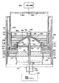
図2には、直径約50.8cm(20インチ)である円筒状中空の薄肉厚のシリコン体を成長させるために好ましい、本発明を具体化する粒子分配器/内側アフターヒータ構造体の改良された形態の加熱炉が図示されている。図2に図示した装置は、ベース部102によってその底端部が閉じられた石英製加熱炉エンクロージェ100を備えている。ベース部102によって支持された中空台座104は支持板106を担持する。グラファイト製サスセプタ108は、幾つかのグラファイト製スタンドオフピン110によって台座104に支持されている。サスセプタ108は、支持板106から隔てられ、その介在する空間には、断熱体として機能するグラファイト製フェルト112の多層が充填されている(便宜上、グラファイト製フェルト幾つかの層は図2に単一の構成要素として図示されている)。サスセプタ108には、ルツボ/ダイ組立体20Aが支持されており、該ルツボ/ダイ組立体20Aは、図1に開示されたルツボ装置20と同様に、グラファイトで出来ており、また、米国特許第5,037,622号の教示内容に従って、多角形ではなくて、円筒体として成長する形態とされている点が相違する。該特許の教示内容は、参考として引用し本明細書に含めてある。サスセプタ108は、ルツボ/ダイユニット20Aの内面を取り巻く立上りフランジすなわちハブ114を有している。追加的なグラファイト製絶縁体122がサスセプタ108及びルツボダイ組立体20Aも取り巻いている。
FIG. 2 shows an improved particle distributor / inner afterheater structure embodying the present invention for growing a cylindrical hollow thin-walled silicon body having a diameter of about 50.8 cm (20 inches). A different form of heating furnace is shown. The apparatus shown in FIG. 2 includes a quartz
加熱炉のベース板102は、グラファイト製供給管124が通って伸びる中央開口部を有している。供給管は、支持板106に形成された穴を通って突き出す、グラファイトで出来た下方の支持管126を貫通して上方に伸びている。
The
支持管126の上端は、ルツボ/ダイユニット20Aの内側部分に重なり合うグラファ
イト製放射遮蔽体130を担持している。
上方支持管134が支持管126内に取り付けられ且つ供給管124を取り巻いている
。下方支持管126の上端は、上方支持管134を受け入れ得るように拡大した内径を有
している。図2に図示するように、管134は、管126の内面に形成された肩部136
上に着座している。管134の上端は、グラファイトで出来た円錐形の粒子供給方向決め
器138(図2及び図3A)内に伸び且つ該方向決め器138を支持している。円錐形部
材138の中心は、供給管124の上端が入る軸方向穴140を有している。円錐形部材
138の下側には、フランジ部分142が設けられており、また、該下側は、全体として
、熱遮蔽体として機能するグラファイト製板144、145によって閉じられている。円
錐形部材138の上面139は、水平面から25°乃至40°の範囲の角度にて伸びることが好ましく、この角度は、その上に落下する粒子が円錐形部材の底端縁まで下方に転がるのを保証するのに十分である。しかし、より大きい又はより小さい角度を採用することもできる。円錐形部材138の底端縁は、図4に最も良く示すように、円筒状の外端縁面146にて終わっている。
The upper end of the
An
Sitting on top. The upper end of the
その頂点に円筒状の管状ハブ150を有する円錐形状のグラファイト製粒子偏向器部材148が円錐形部材138の上方にある。図3Bに最も良く図示するように、上方円錐形部材148の下側部すなわち底面149は、平坦であり且つ下方円錐形部材138の上面139と同一の角度にて伸びている。円錐形部材148の上面151には、一連の同心状の円周方向に伸びる溝152が形成されている。溝152は、図3Bに最も良く図示するように、L字形の断面をしており、また、平坦な環状のグラファイト製板154の形態をしたバッフルを受け入れ得る寸法とされている。この場合、外径が同一寸法の6つの板154A乃至154Fがある。板の内径は、板154Aから板154Fまで漸進的に大きくなり、板の内端縁155は上方円錐形部材148の溝152内に入れ子式に嵌まっている。
Above the
図2及び図3Bを更に参照すると、円錐形部材148は、グラファイトで出来た円筒状の内側アフターヒータ部材160を支持する肩部として機能する周縁リブ158を有している。内側アフターヒータ部材は、板154A乃至154Fの外端縁を取り巻き且つ該外端縁に接近しており、また、その上端縁は、頂部板164に形成された溝162内に着座している。該頂部板は、ねじ付きのグラファイト製栓168を受け入れ得る寸法とされた中央穴166を有している。ねじ付きのグラファイト製栓は、円錐形部材148のハブ150内にねじ込まれ、該円錐形部材には、図3Bに参照番号170で示すように、内ねじが形成されている。栓168がハブ150と係合することは、単一の構造体を形成し得るように円筒体160を円錐状部材148に接続された状態に保つ働きをする。
With further reference to FIGS. 2 and 3B, the
図2乃至図3Aを再度参照すると、粒子偏向器部材148は、円錐形部材138に形成
された穴176及び板144、145及び遮蔽体130に形成されたその他の整合穴を貫
通して伸びる複数のグラファイト製スタンドオフピン174によって支持されており、ま
た、サスセプタ108のハブ114に形成された盲穴内に受け入れられている。スタンド
オフピン174は、サスセプタ108のハブ部分114の周りで円周方向に隔てられてお
り、また、上方円錐形部材148の下面149と下方の円錐形部材138の平行な上面1
39との間に狭小な隙間を提供するような長さを有している。好ましくは、但し、必須で
はないが、該隙間は、3.048mm(0.12インチ)乃至5.08mm(0.20イ
ンチ)の範囲とする。
Referring again to FIGS. 2-3,
It has such a length as to provide a narrow gap with 39. Preferably, but not necessarily, the gap is in the range of 3.048 mm (0.12 inches) to 5.08 mm (0.20 inches).
次に、図3B及び図4を参照すると、上方円錐形部材148には、底端部に逆又は内方に曲がったリップ部180が形成されている。好ましくは、該リップ部180は、円筒状の内端縁の面182に接続された傾斜(円錐形)上面181を有し、これにより面139、149の間の隙間は、傾斜面181の領域内でその底端部にて増大し、次に、上方円錐形部材148の内端縁の面182の領域内で減少する。
Next, referring to FIGS. 3B and 4, the upper
図示した装置は、内側アフターヒータ円筒体160を取り巻き且つ該内側アフターヒータ円筒体160から隔てられたグラファイト製の外側アフターヒータ190(図2及び図3A)も備えている。アフターヒータ190は、ルツボダイ組立体に形成された穴を貫通して伸び且つサスセプタ108によって支持された複数のグラファイト製スタンドオフピン192によって支持されている。外側アフターヒータ190及びアフターヒータ部材160は、軸方向に伸びる環状の通路を画成し、該環状の通路を通じて結晶管状体200が成長し且つ該結晶管状体をルツボ/ダイユニット20Aから引き離すことができる。好ましくは、外側アフターヒータは、グラファイト製フェルトの形態をした絶縁性媒体210によって取り巻かれるようにする。図示した装置は、また、引張り機構206に取り付けられたグラファイト製種ホルダ204も有している。該種ホルダ204は、その上で結晶体200が成長する種を保持する。一般的な方法に従って、種は、典型的に、同様の断面形態を有する、それ以前に成長した管状体の一部分である。該種ホルダには、成長する結晶体の内部から気体を排気し、これにより成長過程に悪影響を与えるであろう圧力の蓄積を回避するための換気穴208が設けられている。
The illustrated apparatus also includes a graphite outer afterheater 190 (FIGS. 2 and 3A) surrounding the
供給管124は、ベース部102に固定されたキャップ210を通って伸びており、該キャップ210は、融液の補給システム212に結合されており、該補給システム212は、ルツボ内の融液の量を所定の限界値の範囲内に維持し得るように命令に基づいてシリコン粒子を射出し得るようにされている。適宜な融液の補給システムは、G.M.フリードマン(G.M.Freedman)らに対して発行された米国特許第4,968,380号、B.H.マッキントッシュ(B.H.Mackintosh)らに対して発行された米国特許第5,085,728号、F.U.メイヤー(F.U.Meier)らに対して発行された米国特許第5,098,229号に記載されている。
The
上記の構造において、板154A乃至154F及びカバー板164は、引張り軸線に対し平行に、内側アフターヒータ160の長さに沿ってほぼ一定の温度勾配となるのを促進する機能を果たす。また、2つの円錐形部材138、148は、供給管124を介して融液の補給システムから導入されるシリコン粒子の分配器として機能する。円錐形部材148は、粒子偏向器として機能し、円錐形部材138は、粒子方向決め器として機能し、これら2つは、協働してシリコン粒子の流れをルツボ内に導く。粒子は、供給管124を介してかなりの速度で射出される。粒子は、栓168に衝突し且つ面139、140の間の円錐形の隙間内に下方に偏向される。粒子は、隙間に沿って落下し且つ、リブ180の傾斜面181に衝突する。粒子は、傾斜面181から飛び出し勝ちとなり、その一部は、内側円錐体138の外端縁の面146を打撃し、その他は、面146と面182との間の隙間を通って直ちに落下する傾向となる。基本的に、傾斜面181は、粒子の落下を妨害し、このため、粒子は、その後、減速した速度にてルツボ内に落下する。図2を再度参照すると、円錐形部材138、148は、リップ部180の面及び底部円錐体138の隣接する面146により形成された排出オリフィスは、融液を保持するルツボの部分の内径と外径との間に実質的に中心があるような寸法とされている。このことは、融液内に落下する粒子は、ルツボのハブ部分に衝突し得ないことを保証する。更に、リップ部180との係合に起因する粒子の速度の低下は、粒子が融液の撥ね出しを殆ど又は全く生じさせないことを保証する。上記の構造の結果、キノコ形状部分の問題は解消され又は実質的に軽減される。
In the above structure, the
粒子が融液内に落下するときの速度は、面139、149の角度の関数であり、また、これらの面がより浅い角度で伸びるようにすることは、粒子がルツボ内に落下するときの速度を遅くするのに役立つことが分かった。従って、リップ部180は、以下に説明する代替的な実施の形態におけるように、省略することができる。
The speed at which the particles fall into the melt is a function of the angle of the
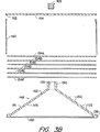
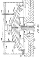
図5A及び図5Bには、例えば、「八角形」のような多角形の断面形状の中空体を成長させるのに好ましい、本発明の1つの改変例が図示されている。図5Aには、図5Bの下側部分が示され、図5Bには、共通の構造体の上側部分が示してある。この点に関して、図5A及び図5Bは、概略図を示すものであり、加熱炉エンクロージャ、外側アフターヒータ、ルツボ及びサスセプタの外側部分は省略されていることを理解すべきである。しかし、図5の実施の形態は図2に示した加熱炉と共に使用されることを理解すべきである。 FIGS. 5A and 5B illustrate one modification of the present invention that is preferred for growing a hollow body with a polygonal cross-sectional shape such as, for example, an “octagon”. 5A shows the lower part of FIG. 5B and FIG. 5B shows the upper part of the common structure. In this regard, it should be understood that FIGS. 5A and 5B are schematic and the outer portions of the furnace enclosure, outer afterheater, crucible and susceptor are omitted. However, it should be understood that the embodiment of FIG. 5 is used with the furnace shown in FIG.
図5A及び図5Bに図示した装置は、ルツボ/ダイ組立体20Aを支持するサスセプタ108を備えている。ルツボ/ダイユニット20Aの毛管ダイ部分、好ましくは該装置のルツボ部分の外壁、また外側アフターヒータ(図示せず)は、平面図で見たとき、成長させるべき中空体の多角形の断面形態に適合し得るような形状とされている。この場合、ルツボの中央ハブ36はサスセプタハブ114の上方となる内側リップ部すなわちフランジ230を有しており、該フランジは下方支持管126Aに取り付けられ且つ該下方支持管を取り巻くグラファイト製スペーサ部材232により隔てられている。該下方支持管は、供給管124の案内部として機能する上方支持管134Aを取り巻き且つ該上方支持管134Aを支持している。グラファイト製スタンドオフリング236がルツボハブ36上に着座している。グラファイトで出来ており且つ傘状部として機能し、また、部材138と同等の機能を果たすテーパー付きの粒子方向決め部材240がスタンドオフリングに着座している。部材240の上面242は、実質的に平坦であり且つ円錐形の断面プロフィールを提供し得るように水平面に対し選んだ角度で傾斜している。この場合、面242は、図2の相応する円錐形部材138の面139よりも浅い角度で伸びる状態で示してある。面242は、その周縁にて外端縁の面244に接続されている。該外端縁の面は円筒状であり、上面242は円錐形である。方向決め部材240は、上方支持管134Aの上端を受け入れ得るようにさら穴とされた中央穴を有している。供給管124の上端は管134Aを貫通して部材242の頂点まで伸びている。
The apparatus illustrated in FIGS. 5A and 5B includes a
図5A及び図5Bの装置は、また、図2の部材148と同等の機能を果たすテーパー付きの粒子偏向器部材250も有している。粒子偏向器部材250は、頂部フランジ253を有する中央のねじ付き開口部252を備えている。栓254は開口部252内に嵌まる。部材250は垂下する側端縁壁258も有している。該垂下する側端縁壁は、平面図で見たとき丸い形態であり、その内面260は供給管124の軸線に対し平行に伸びている。上方円錐形部材250の内側(底部側)円錐形面262は平坦であり且つ下方円錐形部材240の上面242と実質的に等しい角度で伸びている。側壁258は、その底端部に環状板270に対する支持体として機能する周縁フランジ268を有している。板270は、側壁258と同一の多角形の断面形状を有するグラファイト製の内側アフターヒータ272を支持している。図示しないが、内側アフターヒータ272は成長すべき多角形体の各側部に1つずつ設けられた、複数の平坦なグラファイト製板から成っており、これらの板は、図示するように板270の溝内に着座していることが好ましい。
The apparatus of FIGS. 5A and 5B also has a tapered
偏向器部材250には、連続的な円形ボス274が形成されており、該円形ボスは、複数の平坦なグラファイト製板278に接続するために使用されるねじ付き連結ロッド276を受け入れるねじ穴を有しており、該複数の平坦なグラファイト製板はアフターヒータ272の軸線に対し平行な熱勾配を保証する働きをする。連結ロッドにおけるスペーサ管282は板278の間に選ばれた間隔を保つ働きをする。頂部板284は、外側アフターヒータ272を構成する板の上端と相互係止し得るよう溝が形成されている。連結ロッド276の上端のナット286は、支持板285を頂部板284に対して押し付け、これにより板278、アフターヒータ272及び板270が部材250に対し係止され、単一構造体を形成し得るようにする働きをする。該構造体は、板270及びルツボ/ダイユニット20Aの盲穴内に受け入れられる複数のスタンドオフピン288によって支持されている。ピン288は、図示するように、板270をルツボ/ダイユニットに近接する位置に保ち得るような長さを有しており、面242、262の間の間隔は、粒子が面242に沿って下方に自由に流れることを保証するのに十分に大きいが、粒子が栓254によって偏向されたとき、粒子の軌跡を制御するのに十分に小さい。
The
この配置において、供給管124を介して導入された粒子は偏向器の栓254に衝突す
る。次に、粒子は、栓254によって偏向され、2つの部材240、250の間に形成さ
れた隙間290内に落下する。粒子は、隙間290に沿って下方に面244、260の間
の環状空間内に移動する。粒子が隙間290に沿って下方に移動するとき、これら粒子は
、面260の高さに沿って垂直に隔てられた異なる箇所にて面260を打撃し勝ちとなる
。粒子の一部は面244に対して面260から飛び出す一方、その他は面260から直接
、融液内に落下する。面244、260の間に形成された排出オリフィスは、ルツボのダ
イ部分とルツボハブ36との間の中間の箇所に粒子を排出し得るように配置されている。
その結果、融液内に落下するシリコン粒子はハブ36と接触しない。また、面260、2
44に衝突する結果、その速度が妨げられるため、粒子は何ら顕著な乱れ又は跳ね出しを
生ぜずに融液内に落下し、これによりより低温となり勝ちなハブ36の上方部分にて液体
シリコンの付着を回避する。
In this arrangement, particles introduced through
As a result, the silicon particles falling into the melt do not come into contact with the
As a result of impinging on 44, the velocity is hindered so that the particles fall into the melt without causing any noticeable turbulence or splashing, thereby causing the liquid silicon in the upper part of the
図2を再度参照すると、本発明の第二の側面は結晶成長装置と関係した誘導加熱手段に関する。図2には、加熱炉エンクロージャを取り巻く2つの加熱コイル296、298が概略図的に図示されており、コイル296は2つの巻線部を有し、コイル298は単一の巻き線部を有する。しかし、各コイルの特徴である巻き線部の数は変更可能である。機械的手段(図示せず)はコイル296、298を加熱炉エンクロージャと同心状の関係に支持する。好ましくは、コイル296はそのエネルギの殆どを該構成要素に付与し得るようにサスセプタ108の高さに配置される一方、該構成要素は、ルツボに熱を提供する。コイル298は外側アフターヒータ190の底端部を取り巻くように配置され、これにより双方のアフターヒータに熱を加え得るようにすることが好ましい。ファラデーリング300はコイル298の上方で加熱炉エンクロージャを取り巻く関係に配置されている。機械的手段(図示せず)は、ファラデーリングがコイル298に向け又はコイル298から離れて垂直方向に動き得るようにファラデーリングを支持している。図示しないが、コイル296、298は適宜な電源と直列に接続されており、これにより、これらコイルは、該コイルが取り巻く要素を誘導加熱し得るように励起させることができる。「短くした巻線部」又は「短くしたリング」としても既知であるファラデーリングは、二次加熱コイル298の磁界と相互作用し、その結果、該ファラデーリングは、コイル298を励起させることにより発生された磁界を歪ませ且つ該磁界に対抗する磁界を提供する。リング300をコイル298に接近するように移動させると、該対抗する磁界が増大する。コイル298の磁界を変化させることは、該コイル内で磁界上を流れる電流とコイル296内を流れる電流との比率に影響を与える。対抗する磁界に起因する正味効果は、コイル298の有効熱出力を減少させ、これによりその熱入力とコイル296の熱入力との比率を修正することである。実際には、ルツボ及び外側アフターヒータへの熱入力が成長過程を最適化するものであると操作者が満足する迄、ファラデーリングの位置が調節される。
Referring again to FIG. 2, the second aspect of the present invention relates to induction heating means associated with the crystal growth apparatus. FIG. 2 schematically shows two
上述した装置の改良は、「キノコ形状部分」の問題を、解消し又は実質的に軽減し且つ2つの隣接する加熱コイルの加熱効果を制御する効果的な方法を提供するという有利な効果をもたらす。更なる有利な効果は、図1に図示するように、改良された粒子分配器/内側アフターヒータ構造体を結晶成長装置内に取り付けるために、該装置又は中空体を成長させる方法に何ら実質的な変更を加えることが不要な点である。この点に関して、本発明はルツボへの粒子の供給を一層良くしつつ、上記米国特許第5,037,622号に開示され且つ特許請求の範囲に記載された発明の有利な効果の全てを保持することを認識すべきである。 The improvement of the device described above has the advantageous effect of eliminating or substantially mitigating the “mushroom shaped part” problem and providing an effective way to control the heating effect of two adjacent heating coils. . A further advantage is that there is no substantial effect on the method of growing the device or hollow body for mounting the improved particle distributor / inner afterheater structure in the crystal growth device, as illustrated in FIG. It is unnecessary to make any changes. In this regard, the present invention retains all of the advantageous effects of the invention disclosed in the above-mentioned U.S. Pat. No. 5,037,622 while further improving the supply of particles to the crucible. It should be recognized that
関係する本発明の範囲から逸脱せずに、上記の装置にて特定の変更及び改変を具体化することが可能である。このように、例えば、毛管ルツボ/ダイユニットの上端面は、円形、楕円形、三角形、矩形又はその他の断面形態を有する中空体を製造し得る設計とすることができる。また、図面に図示した構造体の異なる部分の相対的寸法は変更可能である。例えば、偏向器及び方向決め器の部材の対向する面の角度は、粒子が融液内に排出されるときの速度を調節し得るよう且つ異なる寸法の中空体を成長させるために必要とされるように、ルツボ/ダイユニットの寸法の変化に従って変えることが可能である。 Certain changes and modifications may be embodied in the above-described apparatus without departing from the scope of the present invention concerned. Thus, for example, the upper end surface of the capillary crucible / die unit can be designed to produce a hollow body having a circular, elliptical, triangular, rectangular or other cross-sectional shape. Further, the relative dimensions of different parts of the structure shown in the drawings can be changed. For example, the angles of the opposing faces of the deflector and director members are required to adjust the rate at which the particles are discharged into the melt and to grow different sized hollow bodies. Thus, it is possible to change according to changes in the dimensions of the crucible / die unit.
本発明の原理から逸脱せずに、ルツボ/ダイ組立体の設計のその他の変更も具体化可能である。このように、例えば、ルツボ及びEFGダイは図面に図示した一体型のルツボ/ダイユニット20Aと機能的に同等物を形成し得るように互いに組み立てられる2つの別個で且つ相違する部材として形成することができる。また、図5A及び図5Bの粒子分配器/内側アフターヒータ構造体は、大きい円筒体を成長させるために使用し得るよう改変することができ、図2乃至図4の相応する構造体は八角形又は多角形又はその他の断面形態を有するその他の結晶体を成長させるときに使用し得るよう改変することができる。この点に関して、方向決め器部材240の面244及び偏向器部材250の垂下壁258は、八角形の断面の中空体を成長させる場合、平面図で見たとき、例えば、八角形のような多角形となるような形状とすることが可能であることを理解すべきである。本発明は管状の中空体を成長させる改良された装置及び方法に関するものであるが、当該技術分野の当業者は、EFG法及び装置に関係するその他の発行特許に記載されたように、所要形状のその他の結晶材料を成長させるためにも使用可能であることが理解されよう。シリコン以外の材料の結晶体を成長させるとき、例えば、ルツボ/ダイユニット、アフターヒータ、放射遮蔽体のようなEFG成長領域の幾つかの構成要素は、適宜な組成、純度及び強度を有する結晶体が得られるようにグラファイト以外の材料で製造する必要があろう。
Other modifications of the crucible / die assembly design can be implemented without departing from the principles of the present invention. Thus, for example, the crucible and the EFG die are formed as two separate and distinct members that are assembled together so that they can form a functional equivalent to the integrated crucible /
更にその他の可能な改変例は当該技術分野の当業者に明らかであろう。このため、上記の説明に含め又は添付図面に示した全ての事項は単に一例にしか過ぎず、限定的なものではないと解釈されることを意図するものである。 Still other possible modifications will be apparent to those skilled in the art. Accordingly, all matter contained in the above description or shown in the accompanying drawings is intended to be interpreted as illustrative only and not restrictive.
Claims (27)
中央開口部を画成する底部壁と、外側壁と、内側壁とを有するルツボであって、該底部壁及び該側壁が共同して前記選ばれた材料の液体供給分を保持する環状の内部空間を画成するようにした前記ルツボと、該液体供給分から所要形状体を成長させるときに使用される毛管ダイとを有するルツボ/ダイユニットと、
前記ルツボを支持し、前記中央開口部と整合させた中央穴を有するサスセプタと、
前記ルツボの上方に配置されて、供給方向決め器と、供給偏向器と、管状の内側アフターヒータとを備える供給分配器/内側アフターヒータ組立体とを備え、
前記供給方向決め器が、中央開口と、該中央開口を取り巻く傾斜した上面とを有する方向決め部材を備え、
該方向決め部材が、前記ルツボの上方に該ルツボから隔てられて取付けられ、前記傾斜した上面の半径が前記ルツボからの距離の増大に伴って減少するように方位決めされ、
前記供給偏向器が、前記供給方向決め器の上方に取り付けられ、該供給偏向器が、前記方向決め部材の前記傾斜した上面と同軸状で且つ該傾斜した上面に対向する傾斜した内面を有する偏向器部材を備え、
前記傾斜した下面が、該傾斜した下面及び該傾斜した上面間に傾斜した環状隙間を画成し得るように前記傾斜した上面と近接して隔たった関係にあり、
また、中央偏向部材が、前記傾斜した下面の中心にあり、前記方向決め部材の中央開口を通って導入された供給粒子を捕捉し且つ該供給粒子を前記隙間内に偏向させ、
前記管状の内側アフターヒータが、前記毛管ダイと同軸状の関係で前記ルツボの上方にあり且つ前記供給方向決め器及び前記供給偏向器を取り巻く関係にあり、
前記ルツボの前記中央開口部を貫通して伸びる供給管を備え、
前記サスセプタの前記中央穴及び前記方向決め部材の前記中央開口が、粒子供給器から供給粒子を受け取り且つ該粒子を前記中央偏向部材にて排出し、これにより前記供給粒子が前記中央偏向部材に衝突し且つ該中央偏向部材により前記隙間内に偏向されるようにし、
前記方向決め部材及び偏向器部材が、前記ルツボの上方に前記隙間用の環状の排出オリフィスを画成し、 該排出オリフィスが、前記ルツボの内側壁及び外側壁の中間の領域にて前記粒子を前記ルツボ内に排出するように配置されるようにした、管状結晶体を成長させる装置。In an apparatus for growing a tubular crystal of a selected material by the EFG method,
A crucible having a bottom wall defining an central opening, an outer wall, and an inner wall, wherein the bottom wall and the side wall together hold a liquid supply of the selected material A crucible / die unit having the crucible configured to define a space, and a capillary die used to grow a required shape from the liquid supply;
And Sasuse descriptor the crucible and the support, that have a central hole aligned with said central opening,
A supply distributor / inner afterheater assembly disposed above the crucible and comprising a supply director, a supply deflector, and a tubular inner afterheater;
The supply director comprises a directing member having a central opening and an inclined top surface surrounding the central opening;
The orienting member is mounted above the crucible and spaced from the crucible and oriented such that the radius of the inclined top surface decreases with increasing distance from the crucible;
The supply deflector is mounted above the supply direction determiner, the supply deflector having an inclined inner surface that is coaxial with the inclined upper surface of the directing member and faces the inclined upper surface. Comprising a container member,
The inclined lower surface is closely spaced from the inclined upper surface so as to define an inclined annular gap between the inclined lower surface and the inclined upper surface;
A central deflection member is in the center of the inclined lower surface, captures supply particles introduced through the central opening of the directing member and deflects the supply particles into the gap;
The tubular inner after-heater is above the crucible in a coaxial relationship with the capillary die and is in a relationship surrounding the supply director and the supply deflector;
A supply pipe extending through the central opening of the crucible,
The central hole of the susceptor and the central opening of the directing member receive supply particles from a particle feeder and discharge the particles at the central deflection member , whereby the supply particles collide with the central deflection member And being deflected into the gap by the central deflection member ,
The directing member and the deflector member define an annular discharge orifice for the gap above the crucible, the discharge orifice containing the particles in a region intermediate the inner and outer walls of the crucible. An apparatus for growing tubular crystals arranged to be discharged into the crucible .
前記供給偏向器が、前記供給方向決め器により支持される、装置。The apparatus of claim 1.
The apparatus, wherein the supply deflector is supported by the supply director.
前記供給偏向器が、前記ルツボにより支持される、装置。The apparatus of claim 1.
The apparatus, wherein the supply deflector is supported by the crucible.
前記内側アフターヒータが、前記供給偏向器に接続され且つ該供給偏向器により支持される、装置。The apparatus of claim 1.
The apparatus wherein the inner after-heater is connected to and supported by the supply deflector.
前記偏向器部材が傾斜した上面を有し、前記偏向器部材の該傾斜した上面により支持された複数の相互に隔てられたバッフルを更に有する、装置。The apparatus of claim 1.
It said deflector member has an upper surface that is inclined, further having the inclined baffles spaced in a plurality of mutually supported by the upper surface of the deflector member.
前記バッフルが、各々が中央開口部を画成する内端縁を有する板であり、該板の前記内端縁が、前記偏向器部材の前記傾斜した上面に形成された溝内に着座する、装置。The apparatus of claim 5.
The baffles are plates having an inner edge each defining a central opening, the inner edge of the plate seated in a groove formed in the inclined upper surface of the deflector member; apparatus.
前記管状の内側アフターヒータが前記バッフルを取り巻く、装置。The apparatus of claim 5.
The tubular inner afterheater surrounds the baffle.
前記供給偏向器部材が、前記中央穴と同軸状の管状ハブを有し、前記供給偏向器部材の前記管状ハブと、前記内側アフターヒータの上端との上方にあり且つ該管状ハブ及び該上端と係合した中央穴を有する端部板を更に有し、
前記中央偏向部材が、前記供給偏向器部材の前記管状ハブ内に固着され且つ前記端部板を前記管状ハブに固着する作用を果たす栓である、装置。The apparatus of claim 5.
The supply deflector member has a tubular hub coaxial with the central hole, and is above the tubular hub of the supply deflector member and the upper end of the inner after heater, and the tubular hub and the upper end An end plate having an engaged central hole;
The apparatus wherein the central deflecting member is a plug secured within the tubular hub of the supply deflector member and serving to secure the end plate to the tubular hub.
フターヒータにより取り巻かれた複数の相互に隔てられたバッフルを更に有する、装置。The apparatus of claim 1, further comprising a plurality of spaced baffles mounted above the deflector member and surrounded by the inner afterheater.
前記偏向器部材が、周縁フランジを有し、
前記内側アフターヒータが該フランジに着座し且つ該フランジにより支持される、装置。The apparatus of claim 1.
The deflector member has a peripheral flange;
The apparatus wherein the inner after-heater sits on and is supported by the flange.
前記偏向器部材が中央穴を有し、
前記中央偏向部材が、前記偏向器部材の前記中央穴内に取り付けられた栓部材を備える、装置。The apparatus of claim 1.
The deflector member has a central hole;
The central deflecting member comprises said central plug member mounted in the bore of the deflector member.
前記方向決め部材の前記傾斜した上面が底端部を有し、
前記方向決め部材が、その前記傾斜した上面の前記底端部に接続される円周方向に伸びる外端縁面を有し、
該外端縁面が、前記方向決め部材の長手方向軸線に対し平行に伸び、
更に、前記偏向器部材の前記傾斜した下面が底端部を有し、
前記偏向器部材が、前記傾斜した下面の前記底端部に接続される円周方向に伸びる内端縁面を有し、
該内端縁面が、前記方向決め器部材の前記外端縁面に対向し且つ該外端縁面と協働して、前記傾斜した隙間に対する環状の排出オリフィスを画成し、
前記隙間が、前記ルツボの外側壁と内側壁との中間にある前記ルツボの領域と整合される、装置。The apparatus of claim 1.
The inclined top surface of the directing member has a bottom end;
The directing member has an outer edge surface extending in a circumferential direction connected to the bottom end of the inclined upper surface;
The outer edge surface extends parallel to the longitudinal axis of the directing member;
Furthermore, the inclined lower surface of the deflector member has a bottom end,
The deflector member has an inner edge surface extending in a circumferential direction connected to the bottom end of the inclined lower surface;
The inner edge surface is opposed to and cooperates with the outer edge surface of the director member to define an annular discharge orifice for the inclined gap;
The apparatus wherein the gap is aligned with a region of the crucible that is intermediate between an outer wall and an inner wall of the crucible.
前記内端縁面が、前記外端縁面に対し平行に伸びる、装置。The apparatus of claim 12, wherein
The apparatus, wherein the inner edge surface extends parallel to the outer edge surface.
前記内端縁面が、前記外端縁面に対し傾斜した角度で伸びており、前記排出オリフィスの半径方向寸法が前記円錐面からの距離が増すに伴い減少するようにした、装置。The apparatus of claim 12, wherein
The apparatus wherein the inner edge surface extends at an inclined angle with respect to the outer edge surface such that the radial dimension of the discharge orifice decreases with increasing distance from the conical surface.
前記供給方向決め部材と係合し且つ該供給方向決め部材を支持する支持管を更に有する、装置。The apparatus of claim 1.
The apparatus further comprising a support tube that engages and supports the supply direction determining member.
前記供給管が前記支持管を貫通して伸びる、装置。The apparatus of claim 15, wherein
The apparatus, wherein the supply tube extends through the support tube.
前記排出オリフィスが、内端及び外端を有し、
更に、前記方向決め器部材と前記偏向器部材との間の間隔が、前記排出オリフィスの前記外端におけるよりも前記内端における方が広いようにした、装置。The apparatus of claim 1.
The discharge orifice has an inner end and an outer end;
Furthermore, the apparatus is such that the spacing between the director member and the deflector member is wider at the inner end than at the outer end of the discharge orifice.
前記偏向器部材の前記傾斜した下面が、内方に曲がったリブにより終わるようにされた底端部を有し、
前記排出オリフィスが、前記内方に曲がったリブにより一部分画成される、装置。The apparatus of claim 17.
The inclined lower surface of the deflector member has a bottom end adapted to end with an inwardly curved rib;
The apparatus, wherein the discharge orifice is defined in part by the inwardly curved rib.
加熱炉エンクロージャと、
該エンクロージャ内に配置されて、貫通穴を有する熱サスセプタと、
前記エンクロージャ内で前記熱サスセプタによって支持されたルツボ/毛管ダイ組立体であって、前記サスセプタの穴と整合された中央開口部を画成する、底部壁と、外側壁と、内側壁と、前記選ばれた材料の液体供給分を保持する前記開口部を取り巻くルツボと、ルツボ内に保持された融液から供給された液体/固体成長境界を支持し且つ成長した結晶体の断面形態を制御する先端を有する毛管ダイとを有する前記ルツボ/毛管ダイ組立体と、
前記サスセプタの穴及び前記中央開口部を貫通して上方に伸びて、前記選ばれた材料の固体粒子を前記ルツボ/ダイ組立体の上方の空間内に運ぶ気体流を射出するときに使用される供給管と、
前記選ばれた材料の固体粒子を捕捉し且つ該固体粒子を前記ルツボに向けて下方に偏向し得るよう所要位置にて前記供給管の上端の上方に配置された粒子偏向器と、
前記供給管の上端に対し取り巻く関係に支持された粒子方向決め器であって、前記粒子偏向器の下方に配置されており、前記偏向器により下方に偏向された前記選ばれた材料の固体粒子を捕捉し且つ該粒子をルツボ内に向け、これにより前記ルツボ内の前記選ばれた材料の融液を補給し得るような形状及び配置とされた前記粒子方向決め器とを備え、
前記粒子偏向器及び粒子方向決め器が、その間に環状隙間を画成する対向し且つ相互に隔てられた円錐形面を有し、
該隙間が、前記偏向器により偏向される粒子を受け取るような所要位置にある上端と、前記ルツボの前記外側壁及び内側壁の中間の領域にて前記粒子を前記ルツボ内に排出するような所要位置にある底端部とを有する、管状結晶体を成長させる装置。In an apparatus for growing a tubular crystal of a selected material by the EFG method,
A furnace enclosure;
A thermal susceptor disposed in the enclosure and having a through hole;
A crucible / capillary die assembly supported by the thermal susceptor in the enclosure, defining a central opening aligned with a hole in the susceptor; an outer wall; an inner wall; A crucible surrounding the opening for holding a liquid supply of a selected material, a liquid / solid growth boundary supplied from a melt held in the crucible, and a cross-sectional form of the grown crystal are controlled. Said crucible / capillary die assembly having a capillary die having a tip;
Used when injecting a gas stream that extends upwardly through the susceptor hole and the central opening and carries solid particles of the selected material into the space above the crucible / die assembly. A supply pipe;
A particle deflector disposed above the upper end of the supply tube at a required position so as to capture solid particles of the selected material and deflect the solid particles downward toward the crucible;
A support particle orienting device in relation to surrounding to the upper end of the supply pipe is arranged below the particle deflector, the solid particles of the material chosen deflected downward by the deflector And directing the particles into the crucible, thereby providing a particle orientation device shaped and arranged to replenish the selected material melt in the crucible,
The particle deflector and the particle director have opposing and spaced conical surfaces defining an annular gap therebetween;
The clearance is, the upper end in the desired position to receive particles are deflected by the deflector, the required so as to discharge the particles to the crucible by the outer wall and the inner wall of the intermediate region of the crucible An apparatus for growing tubular crystals having a bottom end in position.
前記粒子偏向器が、前記円錐形面の1つを特徴とする円錐形部材を備え、
該円錐形部材により支持された管状の内側アフターヒータ部材を更に有する、装置。The apparatus of claim 19.
The particle deflector comprises a conical member characterized by one of the conical surfaces;
The apparatus further comprising a tubular inner afterheater member supported by the conical member.
前記内側アフターヒータ部材が前記円錐形部材の周縁部分と係合する、装置。The apparatus of claim 20.
The apparatus, wherein the inner after-heater member engages a peripheral portion of the conical member.
前記アフターヒータ部材の横方向に伸び且つ該アフターヒータ部材により取り巻かれた平行な相互に隔てた熱伝導板の形態をした複数のバッフルを更に有する、装置。The apparatus of claim 20.
An apparatus further comprising a plurality of baffles extending in a lateral direction of the after heater member and in the form of parallel mutually spaced heat conductive plates surrounded by the after heater member.
前記熱伝導板が連結ロッドにより前記円錐形部材に係止される、装置。The apparatus according to claim 22,
The apparatus wherein the heat conducting plate is locked to the conical member by a connecting rod.
前記粒子方向決め器が前記供給管により支持される、装置。The apparatus of claim 19.
An apparatus wherein the particle director is supported by the supply tube.
前記粒子偏向器が、前記サスセプタに取り付けられ且つ前記粒子方向決め器の開口部を貫通するスタンドオフピンによって支持される、装置。25. The apparatus of claim 24.
The apparatus, wherein the particle deflector is supported by a standoff pin attached to the susceptor and passing through an opening of the particle director.
前記選ばれた材料の融液を保持するルツボであって、中央開口部を画成し得るように環状である前記ルツボと、
前記融液から前記選ばれた材料の管状結晶体を成長させる成長手段であって、(1)成長すべき管状体の断面形態を決定するため前記ルツボの内部と連通する毛管ダイと、(2)前記結晶体が成長する種を支持する種ホルダと、(3)前記管状結晶体及び前記種ホルダを前記ダイから離れるように引張る引張り手段とを備える前記成長手段と、
前記ルツボを支持し、前記中央開口部と整合した貫通穴を有する熱サスセプタと、
該サスセプタを加熱する電気的手段と、
前記選ばれた材料の固体粒子を前記ルツボの上方の空間内に射出する供給管であって、
前記穴及び前記中央開口部を通って伸び、該管の上端が前記ルツボの上方にて終わるようにした前記供給管と、
前記粒子を捕捉し且つ該粒子を前記ルツボに向けて下方に偏向させるような所要位置にて前記管の前記上端の上方に配置された偏向器と、
前記偏向器から落下する前記選ばれた材料の粒子を捕捉するような所要位置にて前記偏向器の下方で前記供給管を取り巻く方向決め器とを備え、
前記偏向器及び方向決め器が、前記ルツボからの距離の増大に伴って半径が減少し且つ、共同して傾斜した通路を画成する、相互に対向し且つ平行な円錐形面と、粒子を前記通路から前記ルツボ内に排出し得るように環状の排出オリフィスを画成すべく前記円錐形面の周縁にて前記円錐形面に接続された追加的な相互に対向する面とを備える、装置。In an apparatus for growing a tubular crystal of a selected material by the EFG method,
A crucible for holding a melt of the selected material, the crucible being annular so as to define a central opening;
A growth means for growing a tubular crystal of the selected material from the melt; (1) a capillary die communicating with the interior of the crucible to determine the cross-sectional shape of the tubular body to be grown; (2 A seed holder for supporting the seed on which the crystal grows; and (3) a pulling means for pulling the tubular crystal and the seed holder away from the die;
A thermal susceptor that supports the crucible and has a through hole aligned with the central opening;
Electrical means for heating the susceptor;
A supply pipe for injecting solid particles of the selected material into the space above the crucible,
The supply pipe extending through the hole and the central opening such that the upper end of the pipe ends above the crucible;
A deflector disposed above the upper end of the tube at a required position to capture the particles and deflect the particles downwardly toward the crucible;
A directing device surrounding the supply tube below the deflector at a required position to capture particles of the selected material falling from the deflector;
The deflector and the orienting device have opposing conical and parallel conical surfaces that define a joint that slopes with increasing radius from the crucible and jointly slopes; And an additional opposing surface connected to the conical surface at the periphery of the conical surface to define an annular discharge orifice for discharge from the passage into the crucible.
画成された、液体シリコンを保持するチャンバを有する開放頂部式ルツボ内にシリコン粒子を導入する方法において、
シリコン粒子を前記中央開口部を通じて前記ルツボの上方の空間内に上方へ射出することと、
該射出された粒子を捕捉し且つ該粒子を前記ルツボの内壁及び外壁間にて前記チャンバの真上に垂直方向排出オリフィスを形成する、1対の隣接面の間に形成された傾斜する通路内に向けることと、
流路の角度を変更した後、前記粒子を前記オリフィスを介して前記通路から排出し、前記粒子が前記排出オリフィスを介して前記チャンバ内に垂直に落下するようにすることとを備える、開放頂部式ルツボ内にシリコン粒子を導入する方法。In a method of introducing silicon particles into an open top crucible having a chamber for holding liquid silicon defined by an outer wall and an annular inner wall defining a central opening and a bottom wall extending between the outer wall and the inner wall ,
Injecting silicon particles upward into the space above the crucible through the central opening;
In a sloping passage formed between a pair of adjacent surfaces that captures the ejected particles and forms a vertical discharge orifice between the inner and outer walls of the crucible directly above the chamber To point to
After changing the angle of the flow path, the particles are discharged from the passage through the orifice, such that the particles fall vertically into the chamber through the discharge orifice. A method of introducing silicon particles into a crucible.
Applications Claiming Priority (2)
| Application Number | Priority Date | Filing Date | Title |
|---|---|---|---|
| US09/826,073 US6562132B2 (en) | 2001-04-04 | 2001-04-04 | EFG crystal growth apparatus and method |
| PCT/US2001/049725 WO2002081044A2 (en) | 2001-04-04 | 2001-12-20 | Efg crystal growth apparatus and method |
Publications (3)
| Publication Number | Publication Date |
|---|---|
| JP2004525852A JP2004525852A (en) | 2004-08-26 |
| JP2004525852A5 JP2004525852A5 (en) | 2005-07-28 |
| JP4147112B2 true JP4147112B2 (en) | 2008-09-10 |
Family
ID=25245624
Family Applications (1)
| Application Number | Title | Priority Date | Filing Date |
|---|---|---|---|
| JP2002579081A Expired - Fee Related JP4147112B2 (en) | 2001-04-04 | 2001-12-20 | EFG crystal growth apparatus and method |
Country Status (8)
| Country | Link |
|---|---|
| US (1) | US6562132B2 (en) |
| EP (1) | EP1372805B1 (en) |
| JP (1) | JP4147112B2 (en) |
| CN (1) | CN100354459C (en) |
| AU (1) | AU2002249835A1 (en) |
| DE (1) | DE60140215D1 (en) |
| HK (1) | HK1063646A1 (en) |
| WO (1) | WO2002081044A2 (en) |
Families Citing this family (15)
| Publication number | Priority date | Publication date | Assignee | Title |
|---|---|---|---|---|
| EP1577954A1 (en) * | 2004-03-09 | 2005-09-21 | RWE SCHOTT Solar GmbH | Method for transporting solid particles |
| US7465351B2 (en) * | 2004-06-18 | 2008-12-16 | Memc Electronic Materials, Inc. | Melter assembly and method for charging a crystal forming apparatus with molten source material |
| US7691199B2 (en) * | 2004-06-18 | 2010-04-06 | Memc Electronic Materials, Inc. | Melter assembly and method for charging a crystal forming apparatus with molten source material |
| US7344594B2 (en) * | 2004-06-18 | 2008-03-18 | Memc Electronic Materials, Inc. | Melter assembly and method for charging a crystal forming apparatus with molten source material |
| US7572334B2 (en) * | 2006-01-03 | 2009-08-11 | Applied Materials, Inc. | Apparatus for fabricating large-surface area polycrystalline silicon sheets for solar cell application |
| DE102006041736A1 (en) * | 2006-09-04 | 2008-03-20 | Schott Solar Gmbh | Method and device for producing a pipe |
| DE102006062117A1 (en) * | 2006-12-22 | 2008-06-26 | Schott Solar Gmbh | Process for producing crystallized silicon and crystallized silicon |
| US20090136731A1 (en) * | 2007-10-23 | 2009-05-28 | Saint-Gobain Ceramics & Plastics, Inc. | Scintillator crystals and methods of forming |
| TW200932963A (en) * | 2008-01-29 | 2009-08-01 | Green Energy Technology Inc | Crystal growing furnace with heating improvement structure |
| DE102009008371A1 (en) * | 2009-02-11 | 2010-08-12 | Schott Solar Ag | Integral process from wafer fabrication to module production for the production of wafers, solar cells and solar modules |
| US9206525B2 (en) | 2011-11-30 | 2015-12-08 | General Electric Company | Method for configuring a system to grow a crystal by coupling a heat transfer device comprising at least one elongate member beneath a crucible |
| CN102560630A (en) * | 2012-01-12 | 2012-07-11 | 徐州协鑫光电科技有限公司 | Thermal field capable of allowing synchronous growth of a plurality of crystals with edge-defined film-fed crystal growth technique and method thereof |
| US20200048790A1 (en) | 2017-03-30 | 2020-02-13 | Kyocera Corporation | Tubular sapphire member, heat exchanger, semiconductor manufacturing device, and method for manufacturing tubular sapphire member |
| CN109234796A (en) * | 2018-11-06 | 2019-01-18 | 四川联合晶体新材料有限公司 | A kind of system and method for EFG technique growing large-size sapphire single-crystal plate |
| CN114293245B (en) * | 2021-12-30 | 2023-02-14 | 连城凯克斯科技有限公司 | Automatic lifting mechanism of single crystal furnace heater |
Family Cites Families (19)
| Publication number | Priority date | Publication date | Assignee | Title |
|---|---|---|---|---|
| US4230674A (en) | 1976-12-27 | 1980-10-28 | Mobil Tyco Solar Energy Corporation | Crucible-die assemblies for growing crystalline bodies of selected shapes |
| US4443411A (en) * | 1980-12-15 | 1984-04-17 | Mobil Solar Energy Corporation | Apparatus for controlling the atmosphere surrounding a crystal growth zone |
| US4647437A (en) | 1983-05-19 | 1987-03-03 | Mobil Solar Energy Corporation | Apparatus for and method of making crystalline bodies |
| US4661324A (en) * | 1985-02-15 | 1987-04-28 | Mobil Solar Energy Corporation | Apparatus for replenishing a melt |
| JPS61214398A (en) * | 1985-03-20 | 1986-09-24 | 株式会社日立製作所 | High frequency heater for nuclear fuser |
| US4726831A (en) * | 1987-01-12 | 1988-02-23 | Corning Glass Works | Molten glass delivery and conditioning system |
| US5085728A (en) | 1987-05-05 | 1992-02-04 | Mobil Solar Energy Corporation | System for controlling crystal growth apparatus and melt replenishment system therefor |
| JPS63291888A (en) * | 1987-05-25 | 1988-11-29 | Shin Etsu Handotai Co Ltd | Production device for semiconductor single crystal |
| CA1334841C (en) * | 1988-09-13 | 1995-03-21 | Mamoru Kioka | Olefin polymerization catalyst component, process for production thereof, olefin polymerization catalysts, and process for polymerizing olefins |
| US5156978A (en) | 1988-11-15 | 1992-10-20 | Mobil Solar Energy Corporation | Method of fabricating solar cells |
| US5106763A (en) | 1988-11-15 | 1992-04-21 | Mobil Solar Energy Corporation | Method of fabricating solar cells |
| US4968380A (en) | 1989-05-24 | 1990-11-06 | Mobil Solar Energy Corporation | System for continuously replenishing melt |
| US4997628A (en) * | 1989-08-24 | 1991-03-05 | Westinghouse Electric Corp. | Web growth configuration for higher productivity and 100% feed rate capability at wide widths |
| US5098229A (en) | 1989-10-18 | 1992-03-24 | Mobil Solar Energy Corporation | Source material delivery system |
| ATE136283T1 (en) * | 1989-10-18 | 1996-04-15 | Ase Americas Inc | SYSTEM FOR FEEDING RAW MATERIALS |
| US5037622A (en) | 1990-07-13 | 1991-08-06 | Mobil Solar Energy Corporation | Wet-tip die for EFG crystal growth apparatus |
| US5558712A (en) | 1994-11-04 | 1996-09-24 | Ase Americas, Inc. | Contoured inner after-heater shield for reducing stress in growing crystalline bodies |
| US6139811A (en) * | 1999-03-25 | 2000-10-31 | Ase Americas, Inc. | EFG crystal growth apparatus |
| US6111908A (en) * | 1999-08-16 | 2000-08-29 | Jones; William R. | High temperature vacuum heater supporting mechanism with cup shaped shield |
-
2001
- 2001-04-04 US US09/826,073 patent/US6562132B2/en not_active Expired - Lifetime
- 2001-12-20 EP EP01998076A patent/EP1372805B1/en not_active Expired - Lifetime
- 2001-12-20 DE DE60140215T patent/DE60140215D1/en not_active Expired - Lifetime
- 2001-12-20 JP JP2002579081A patent/JP4147112B2/en not_active Expired - Fee Related
- 2001-12-20 AU AU2002249835A patent/AU2002249835A1/en not_active Abandoned
- 2001-12-20 CN CNB018231217A patent/CN100354459C/en not_active Expired - Fee Related
- 2001-12-20 WO PCT/US2001/049725 patent/WO2002081044A2/en active Application Filing
-
2004
- 2004-08-23 HK HK04106302A patent/HK1063646A1/en not_active IP Right Cessation
Also Published As
| Publication number | Publication date |
|---|---|
| JP2004525852A (en) | 2004-08-26 |
| US20020144649A1 (en) | 2002-10-10 |
| EP1372805A2 (en) | 2004-01-02 |
| DE60140215D1 (en) | 2009-11-26 |
| WO2002081044A3 (en) | 2003-01-30 |
| EP1372805B1 (en) | 2009-10-14 |
| HK1063646A1 (en) | 2005-01-07 |
| CN100354459C (en) | 2007-12-12 |
| US6562132B2 (en) | 2003-05-13 |
| CN1494608A (en) | 2004-05-05 |
| WO2002081044A2 (en) | 2002-10-17 |
| EP1372805A4 (en) | 2007-02-14 |
| AU2002249835A1 (en) | 2002-10-21 |
Similar Documents
| Publication | Publication Date | Title |
|---|---|---|
| JP4147112B2 (en) | EFG crystal growth apparatus and method | |
| EP0867531B1 (en) | Single crystal production apparatus and process | |
| US6579362B2 (en) | Heat shield assembly for crystal puller | |
| JP2004525852A5 (en) | ||
| US5556461A (en) | Method for producing a silicon single crystal by a float-zone method | |
| KR100490569B1 (en) | Single crystal pulling appratus | |
| US9376762B2 (en) | Weir for improved crystal growth in a continuous Czochralski process | |
| US6423137B1 (en) | Single crystal material supplying apparatus and single crystal material supplying method | |
| JP3911126B2 (en) | EFG crystal growth equipment | |
| JP4555677B2 (en) | Apparatus for producing a crystal rod having a predetermined cross section and a columnar polycrystalline structure by continuous crystallization | |
| JP2003002782A (en) | Method and device for pulling silicon single crystal | |
| JPH06122587A (en) | Apparatus for producing silicon single crystal and its production | |
| JPH0523580Y2 (en) | ||
| US9476141B2 (en) | Weir for inhibiting melt contamination | |
| JP2953697B2 (en) | Silicon single crystal pulling device | |
| US12104275B2 (en) | Ingot puller apparatus having cooling jacket device with cooling fluid tubes | |
| JPH0543107Y2 (en) | ||
| CN116356421A (en) | Single crystal furnace and operation method thereof | |
| GB2155806A (en) | Apparatus for replenishing a melt | |
| JP2567312B2 (en) | Silicon single crystal manufacturing apparatus and manufacturing method | |
| JP2010052982A (en) | Silicon single crystal pulling device | |
| JPH04357190A (en) | Single crystal production apparatus | |
| JPH0312386A (en) | Production of silicon single crystal |
Legal Events
| Date | Code | Title | Description |
|---|---|---|---|
| A621 | Written request for application examination |
Free format text: JAPANESE INTERMEDIATE CODE: A621 Effective date: 20040709 |
|
| A977 | Report on retrieval |
Free format text: JAPANESE INTERMEDIATE CODE: A971007 Effective date: 20070315 |
|
| A131 | Notification of reasons for refusal |
Free format text: JAPANESE INTERMEDIATE CODE: A131 Effective date: 20071005 |
|
| A601 | Written request for extension of time |
Free format text: JAPANESE INTERMEDIATE CODE: A601 Effective date: 20080104 |
|
| A602 | Written permission of extension of time |
Free format text: JAPANESE INTERMEDIATE CODE: A602 Effective date: 20080111 |
|
| A521 | Request for written amendment filed |
Free format text: JAPANESE INTERMEDIATE CODE: A523 Effective date: 20080117 |
|
| TRDD | Decision of grant or rejection written | ||
| A01 | Written decision to grant a patent or to grant a registration (utility model) |
Free format text: JAPANESE INTERMEDIATE CODE: A01 Effective date: 20080611 |
|
| A01 | Written decision to grant a patent or to grant a registration (utility model) |
Free format text: JAPANESE INTERMEDIATE CODE: A01 |
|
| A61 | First payment of annual fees (during grant procedure) |
Free format text: JAPANESE INTERMEDIATE CODE: A61 Effective date: 20080623 |
|
| R150 | Certificate of patent or registration of utility model |
Free format text: JAPANESE INTERMEDIATE CODE: R150 |
|
| FPAY | Renewal fee payment (event date is renewal date of database) |
Free format text: PAYMENT UNTIL: 20110627 Year of fee payment: 3 |
|
| FPAY | Renewal fee payment (event date is renewal date of database) |
Free format text: PAYMENT UNTIL: 20110627 Year of fee payment: 3 |
|
| FPAY | Renewal fee payment (event date is renewal date of database) |
Free format text: PAYMENT UNTIL: 20120627 Year of fee payment: 4 |
|
| FPAY | Renewal fee payment (event date is renewal date of database) |
Free format text: PAYMENT UNTIL: 20130627 Year of fee payment: 5 |
|
| R250 | Receipt of annual fees |
Free format text: JAPANESE INTERMEDIATE CODE: R250 |
|
| R250 | Receipt of annual fees |
Free format text: JAPANESE INTERMEDIATE CODE: R250 |
|
| R250 | Receipt of annual fees |
Free format text: JAPANESE INTERMEDIATE CODE: R250 |
|
| LAPS | Cancellation because of no payment of annual fees |