JP4145128B2 - Airbag - Google Patents
Airbag Download PDFInfo
- Publication number
- JP4145128B2 JP4145128B2 JP2002344208A JP2002344208A JP4145128B2 JP 4145128 B2 JP4145128 B2 JP 4145128B2 JP 2002344208 A JP2002344208 A JP 2002344208A JP 2002344208 A JP2002344208 A JP 2002344208A JP 4145128 B2 JP4145128 B2 JP 4145128B2
- Authority
- JP
- Japan
- Prior art keywords
- base fabric
- base
- airbag
- receiving
- auxiliary
- Prior art date
- Legal status (The legal status is an assumption and is not a legal conclusion. Google has not performed a legal analysis and makes no representation as to the accuracy of the status listed.)
- Expired - Fee Related
Links
Images


Description
【0001】
【発明の属する技術分野】
本発明は乗用車や商用車、バス等の車両において、シートの正面(フロントシートの場合にはステアリングハンドルの中央の内部や、インストルメントパネルの内部等の位置、リヤシートの場合にはフロントシートのシートバックの位置等)に配置されたエアバッグ装置において、エアバッグの構成に関する。
【0002】
【従来の技術】
前述のようなエアバッグは一般に、布体から所定の形状の基布を裁断し、基布を袋状に接合(ミシン縫製、接着剤・高周波・超音波・熱溶着による接合等)することによって構成されている。エアバッグでは単純に丸く膨張させるのではなく、例えば特許文献1に開示されているように、エアバッグにおいて乗員を受け止める受け止め面が、乗員に向けて膨らんだ球面状ではなく平面状になるようにエアバッグを膨張させることが要求されている。
これは、エアバッグが膨張した場合に、平面状の受け止め面で乗員を受け止めることにより、乗員を受け止めた際の負荷が乗員の一部分に集中せずに分散するようにする為である。
【0003】
【特許文献1】
特開2001−260788号公報(図3,4,6)
【0004】
【発明が解決しようとする課題】
特許文献1の構造によると、エアバッグにおいて乗員を受け止める受け止め面(特許文献1の図6中の26(18))は平面状になっているが、受け止め面が乗員から見て三角形状になっているので(特許文献1の図6参照)、受け止め面の面積を大きくすると言う面で改善の余地がある。
又、特許文献1の構造によると、エアバッグが膨張する際、基布と基布とが接合された接合部分(特許文献1の図4及び図6中の13,14)が、膨張したエアバッグの上部の中央に位置している。この場合、インフレータ(特許文献1の図4及び図6中の23に位置する)のガスがエアバッグに流入して、エアバッグが膨張する際、インフレータのガスがエアバッグの上部の中央に当たって持ち上げるような状態になる。これにより、エアバッグの上部の中央の接合部分でインフレータのガスが漏れるような事態が発生すると、エアバッグの膨張が遅れると言う事態に発展する可能性が考えられる。
【0005】
エアバッグにおいて、受け止め面が平面状になるようにする場合、例えば助手席用のエアバッグのように、インフレータの向きとは少し異なる方向にエアバッグを膨張させる必要があったり、インフレータから乗員までの距離が比較的長いことがあったりする。
さらに、受け止め面が平面状になるようにエアバッグを膨張させる為に、膨張時のエアバッグの形状を規制する補助布をエアバッグの内部に配置することが提案されており、基布の内側に補助布を配置した状態で基布を袋状に接合することになる。この場合、基布に補助布を加えることによって、エアバッグを袋状に構成する際の全体の接合長さが長くなることがあり、生産コストの低減と言う面で改善の余地がある。
【0006】
本発明はエアバッグにおいて、乗員を受け止める受け止め面の面積が大きくなるようにし、エアバッグの接合部分からインフレータのガスが漏れて、エアバッグの膨張が遅れると言う事態に発展する可能性を抑えることを目的としており、インフレータの向きとは少し異なる方向にエアバッグを膨張させる必要があったり、インフレータから乗員までの距離が比較的長いことがあったりする場合のエアバッグにおいて、膨張時のエアバッグの形状を規制する補助布を備えた場合、全体の接合長さが長くならないように構成することを目的としている。
【0007】
【課題を解決するための手段】
[I]
請求項1の特徴によると、展開した状態(接合前の状態)において、エアバッグは第1基布、第2基布、受け止め基布及び補助基布を備えた1枚の布状やシート状になっている(第1及び第2基布の一方の側辺部が接続され(例えば図1及び図11のA1参照)、受け止め基布の一方の側辺部が第1及び第2基布の側辺部に接続されている(例えば図1及び図11のA2,A3参照)。受け止め基布の上辺部又は下辺部に補助基布が接続されている(例えば図1のA4,B2参照)。
【0008】
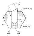
請求項1の特徴によると、以上のような状態のエアバッグにおいて例えば図1及び図2(イ)に示すように、第1基布1の後辺部1bと受け止め基布3の下辺部3bとを接合、第2基布2の後辺部2bと受け止め基布3の上辺部3aとを接合、第1、第2、受け止め基布1,2,3の他方の側辺部1c,1d,2c,2d,3c,3dを接合、第1及び第2基布1,2の前辺部1a,2aと補助基布4,5の端部4a,5aとを接合することによって、エアバッグを袋状に構成することができる。
【0009】
[II]
前項[I]の記載により請求項1の特徴によると、インフレータ6のガスがエアバッグに流入してエアバッグが膨張する際、例えば図4(イ)(ロ)に示すように、インフレータ6のガスが第2基布2を持ち上げながら受け止め基布3に向かって流れる状態となり、第1及び第2基布1,2、補助基布4,5が、車体後方(図4(イ)(ロ)の紙面右方)に延ばされる状態となる。第2基布2の後辺部2b及び受け止め基布3の上辺部3aが持ち上げられて、受け止め基布3が車体上方(図4(イ)(ロ)の紙面上方)に延ばされる状態となる。
【0010】
これにより、請求項1の特徴によると、インフレータのガスがエアバッグに流入してエアバッグが膨張する際、第2基布が持ち上げられながら、第1及び第2基布が車体後方に延ばされる状態になる点、受け止め基布に上及び下辺部、一方及び他方の側辺部が備えられている点によって、第1及び第2基布の後辺部の間にある受け止め基布の面が、乗員から見て円状ではなく矩形状(例えば長方形状)になり易い。
【0011】
請求項1の特徴によると受け止め基布の上辺部又は下辺部に補助基布が接続されているので、受け止め基布の中央部側が膨張しようとする状態が補助基布によって抑えられており、補助基布が接続されていない受け止め基布の横側部が膨張し易い状態となっている。これにより、受け止め基布の中央部側が膨張して受け止め基布が乗員に向けて球面状になる状態が抑えられて、受け止め基布の面が平面状になり易い。
【0012】
この場合に、請求項1の特徴によると、例えば図4(ロ)に示すように、インフレータ6のガスが受け止め基布3に向かって流れる際に、インフレータ6と受け止め基布3との間に補助基布4が位置する状態となるようにすれば、インフレータ6のガスが補助基布4に邪魔されて受け止め基布3の中央部側に流れ難くなり、受け止め基布3の横側部に流れ易くなる。これによって、受け止め基布3の横側部の膨張に対して受け止め基布3の中央部側の膨張が遅れ気味になり、受け止め基布3の面が平面状になり易く、受け止め基布3の中央部側が速く膨張して受け止め基布3の面が乗員に向けて球面状になる状態が抑えられる。
【0013】
[III]
請求項1の特徴によると、前項[II]に記載のように、インフレータのガスがエアバッグに流入してエアバッグが膨張する際、第2基布が持ち上げられながら、第1及び第2基布が車体後方に延ばされる状態になる点によって、エアバッグが膨張する方向は第1及び第2基布によって略決まるので、エアバッグを膨張させたい方向に対してインフレータの向きが少し異なっていても、第1及び第2基布を適切に設定することによって、エアバッグを膨張させたい方向に的確に膨張させることができる。
【0014】
この場合、請求項1の特徴によると、インフレータから乗員までの距離が比較的長いものであれば、これに応じて第1及び第2基布を長いものに構成すればよく、第1及び第2基布の長さによって、エアバッグの膨張時の受け止め基布の位置を乗員に対して適切なものに設定することができる。
【0015】
[IV]
請求項1の特徴によると、第2基布の中央がエアバッグの上部の中央となる(図4(ロ)参照)。この場合、前項[I]に記載のように、第1及び第2基布の一方の側辺部が接続され、第1及び第2基布の他方の側辺部を接合されているので、第2基布の中央に接合部分が存在する状態にはならない。
【0016】
これにより、請求項1の特徴によると、インフレータのガスがエアバッグに流入してエアバッグが膨張する際、インフレータのガスがエアバッグの上部の中央(第2基布の中央)に当たって持ち上げるような状態になっても、エアバッグの上部の中央(第2基布の中央)に接合部分が存在しないので、特許文献1のように、エアバッグの上部の中央の接合部分でインフレータのガスが漏れるような事態が発生することはない。
【0017】
[V]
請求項1の特徴によると前項[I]に記載のようにエアバッグを袋状に構成する場合、第1及び第2基布の外周部(前及び後辺部、側辺部)を接合する程度で、エアバッグを袋状に構成することができる点、第1及び第2基布の一方の側辺部が事前に接続されているので、第1及び第2基布の外周部(前及び後辺部、側辺部)の全てを接合する必要がない点、並びに第1及び第2基布の外周部(前及び後辺部、側辺部)を接合する際に、受け止め基布の上及び下辺部、補助基布の端部も一緒に接合することが可能である点によって、エアバッグを袋状に構成する際の全体の接合長さを短いものに抑えることができる。
請求項1の特徴によると、第1基布、第2基布、受け止め基布及び補助基布を1枚の布体により一体的に構成している。
これによって、請求項1の特徴によると、第1基布、第2基布、受け止め基布及び補助基布を、別々に用意してミシン縫製等により接合し、前項[I]に記載のような展開した状態(接合前の状態)のエアバッグを得ると言うようなことを行う必要がない。
【0018】
[VI]
請求項2の特徴によると、請求項1の場合と同様に前項[I]〜[V]に記載の「作用」を備えており、これに加えて以下のような「作用」を備えている。
請求項2の特徴によると、インフレータに取り付けられる取付部を第1基布に備えた場合、第1基布の取付部と一緒にインフレータに取り付けられる取付部を補助基布に備えている。
これにより請求項2の特徴によると、第1基布及び補助基布の取付部がインフレータに取り付けられるので、第1基布の取付部のみをインフレータに取り付ける場合に比べて、エアバッグのインフレータへの取付強度を高いものにすることができる。
【0019】
【0020】
【発明の実施の形態】
[1]
図1はエアバッグを展開した状態(接合前の状態)であり、第1基布1、第2基布2、受け止め基布3、第1補助基布4及び第2補助基布5を備えており、第1基布1、第2基布2、受け止め基布3、第1及び第2補助基布4,5が1枚の布体10(図6参照)から一体的に裁断されて構成されている。
【0021】
図1に示すように、第1基布1は6角形状をしており(第1山折り線部A1及び第2山折り線部A2参照)、膨張時の車体前方側に対応する前辺部1a、膨張時の車体後方側に対応する後辺部1b、膨張時の車体右方及び左方側の一方に対応する第1側辺部1c及び第2側辺部1dが備えられ、後述するインフレータ6を取り付ける為の開口1eが前辺部1aの近傍に備えられている。第1基布1において、膨張時の車体右方及び左方側の他方に対応する側辺部は、第1及び第2山折り線部A1,A2を介して、第2基布2及び受け止め基布3につながっている。
【0022】
図1に示すように、第2基布2は第1基布1と同じ形状及び同じ大きさの6角形状をしており(第1山折り線部A1及び第3山折り線部A3参照)、膨張時の車体前方側に対応する前辺部2a、膨張時の車体後方側に対応する後辺部2b、膨張時の車体右方及び左方側の一方に対応する第1側辺部2c及び第2側辺部2dが備えられている。第2基布2において、膨張時の車体右方及び左方側の他方に対応する側辺部は、第1及び第3山折り線部A1,A3を介して、第1基布1及び受け止め基布3につながっている。
【0023】
図1に示すように、受け止め基布3は細長い6角形状をしており(第2及び第3山折り線部A2,A3参照)、中央に第1谷折り線部B1が設定されている。膨張時の車体上方側に対応する上辺部3a、膨張時の車体下方側に対応する下辺部3b、膨張時の車体右方及び左方側の一方に対応する第1側辺部3c及び第2側辺部3dが、受け止め基布3に備えられている。受け止め基布3において、膨張時の車体右方及び左方側の他方に対応する側辺部は、第2及び第3山折り線部A2,A3を介して、第1及び第2基布1,2につながっている。
【0024】
図1に示すように第1補助基布4は長方形状をしており(第2谷折り線部B2参照)、第2谷折り線部B2を介して受け止め基布3の上辺部3aの中央部につながっている。第1補助基布4において後述するインフレータ6を取り付ける為の開口4bが端部4aの近傍に備えられ、開口4bと第2谷折り線部B2との間に抜け口4cが備えられている。
【0025】
図1に示すように、第2補助基布5は第1補助基布4と同じ形状及び同じ大きさの長方形状をしており(第4山折り線部A4参照)、第4山折り線部A4を介して受け止め基布3の下辺部3bの中央部につながっている。第2補助基布5において、後述するインフレータ6を取り付ける為の開口5bが端部5aの近傍に備えられている。この場合、第2補助基布5よりも第1補助基布4が少し長いものに設定されている。
【0026】
[2]
次に、前項[1]に記載のような展開した状態(接合前の状態)のエアバッグを袋状に接合する工程について説明する。
図1に示す展開した状態(接合前の状態)のエアバッグにおいて、図2(イ)に示すように、第1,2,3山折り線部A1,A2,A3を山折りして、第1及び第2基布1,2を重ね合わせる。第1谷折り線B1を谷折りして、受け止め基布3を2つ折りにし、第1及び第2基布1,2の間に、受け止め基布3を挟み込む。図2(ロ)に示すように、第4山折り線部A4を山折りし、第2谷折り線部B2を谷折りして、第1及び第2補助基布4,5を重ね合わせながら、第1及び第2補助基布4,5を第1基布1(第2基布2とは反対側)に重ね合わせる。
【0027】
これにより、図2(イ)(ロ)及び図3(イ)に示すように、第1基布1の後辺部1bと受け止め基布3の下辺部3b、第1基布1の第1側辺部1cと受け止め基布3の第1側辺部3c、第2基布2の後辺部2bと受け止め基布3の上辺部3a、第2基布2の第1側辺部2cと受け止め基布3の第2側辺部3dとが合わされる。第1基布1の第2側辺部1dと第2基布2の第2側辺部2d、第1基布1の前辺部1aと第2基布2の前辺部2aとが合わされる。第1及び第2基布1,2の前辺部1a,2aと第1及び第2補助基布4,5の端部4a,5a、第1基布1の開口1eと第1及び第2補助基布4,5の開口4b,5bとが合わされる。
【0028】
図2(イ)(ロ)及び図3(イ)に示すように第1基布1の後辺部1bと受け止め基布3の下辺部3b、第1基布1の第1側辺部1cと受け止め基布3の第1側辺部3cとを、ミシン縫製によって接合する。第2基布2の後辺部2bと受け止め基布3の上辺部3a、第2基布2の第1側辺部2cと受け止め基布3の第2側辺部3dとを、ミシン縫製によって接合する。第1基布1の第2側辺部1dと第2基布2の第2側辺部2d、第1基布1の前辺部1aと第2基布2の前辺部2aとを、ミシン縫製によって接合する。第1及び第2基布1,2の前辺部1a,2aと第1及び第2補助基布4,5の端部4a,5aとを、ミシン縫製によって接合する。
【0029】
以上のようにして接合した後に、図3(イ)(ロ)から図3(ハ)に示すように、第1及び第2基布1,2、第1及び第2補助基布4,5を180°反転させる。これにより、第1及び第2基布1,2の前辺部1a,2aと第1及び第2補助基布4,5の端部4a,5aとが、外向き(図3(イ)(ロ)参照)から内向き(図3(ハ)参照)になり、第1基布1と第1及び第2補助基布4,5との間に、第2基布2が位置する状態となる。
【0030】
次に図3(ハ)から図3(ニ)に示すように、第1基布1の開口1eに第2基布2、第1及び第2補助基布4,5を入れ込んでいき、全体を反転させる。これによって、図4(イ)に示すように、第1及び第2基布1,2の前辺部1a,2a、後辺部1b,2b、第1及び第2側辺部1c,2c,1d,2d、受け止め基布3の上辺部3a、下辺部3b、第1及び第2側辺部3c,3d、第1及び第2補助基布4,5の端部4a,5aが内向きになる。
【0031】
[3]
前項[1][2]に記載のようにして得られたエアバッグは助手席用であり、図4(イ)に示すように、第1基布1、第1及び第2補助基布4,5の開口1e,4b,5bにインフレータ6及び上側の押さえ板7を挿入して、上及び下側の押さえ板7,8により、第1基布1、第1及び第2補助基布4,5の開口1e,4b,5bの周辺部を挟み込んで、ボルトによって締め付ける。
【0032】
これにより、インフレータ6がエアバッグに取り付けられた状態となるのであり、図5(イ)に示すようにインストルメントパネル9の上部の内側に、エアバッグ及びインフレータ6を配置する。この場合、インフレータ6は車体上方の向きか少し斜め後方の車体上方の向きになるのであり、インフレータ6の上側に第2基布2が被さる状態になって(図4(イ)参照)、インフレータ6が第1及び第2基布1,2の前辺部1a,2aの近傍、第1及び第2補助基布4,5の端部4a,5aの近傍に位置する状態となる。
【0033】
以上の状態においてインフレータ6のガスによりエアバッグが膨張する際、図4(ロ)及び図5(ロ)に示すように、インフレータ6のガスが第2基布2を持ち上げながら受け止め基布3に向かって流れる状態となり、第1及び第2基布1,2、第1及び第2補助基布4,5が車体後方に延ばされる状態となる。第2基布2の後辺部2b及び第1補助基布4が持ち上げられて、受け止め基布3の上辺部3aが持ち上げられ、2つに折り畳まれていた受け止め基布3が車体上方に延ばされる状態となる。受け止め基布3の第1及び第2側辺部3c,3dの付近、他方の側辺部の付近が車体後方に向けて折れ曲がり、乗員から見て受け止め基布3が長方形状になる。
【0034】
この場合、インフレータ6のガスが受け止め基布3に向かって流れる際、図4(ロ)に示すように、インフレータ6と受け止め基布3との間に第1補助基布4が位置する状態となるので、インフレータ6のガスが第1補助基布4に邪魔されて受け止め基布3の中央部に流れ難くなり、受け止め基布3の第1及び第2側辺部3c,3d、他方の側辺部に流れ易くなる。これにより、受け止め基布3の横側部の膨張に対して受け止め基布3の中央部の膨張が遅れ気味になり、受け止め基布3が平面状になり易く、受け止め基布3の中央部が速く膨張して受け止め基布3が乗員に向けて球面状になる状態が抑えられる。
【0035】
図1及び図4(ロ)に示すように、第1及び第2補助基布4,5が受け止め基布3の上辺部3a及び下辺部3bの中央部につながっていることにより、受け止め基布3の中央部が膨張しようとする状態が抑えられており、受け止め基布3の横側部が膨張し易い状態となっている。これにより、受け止め基布3の中央部が膨張して受け止め基布3が乗員に向けて球面状になる状態が抑えられて、受け止め基布3が平面状になり易い。
【0036】
[発明の実施の第1別形態]
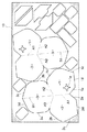
前述の[発明の実施の形態]において、展開した状態のエアバッグを1枚の布体10から複数枚だけ一体的に裁断する場合、図6に示すようにエアバッグの向きを交互に逆向きにしながら並べて、隣接するエアバッグの第1補助基布4が並ぶようにし、隣接するエアバッグの第2補助基布5が並ぶようにする。
【0037】
前述のように構成すると1枚の布体10において、裁断するエアバッグ以外の部分を少なくすることができ、歩留りを良いものにすることができる。この場合、1枚の布体10に対し裁断されるエアバッグの向きが互いに正反対になるだけで、1枚の布体10に対するエアバッグの方向性が均一になるので、エアバッグの性能のバラ付きが少なくなる。
【0038】
[発明の実施の第2別形態]
前述の[発明の実施の形態]及び[発明の実施の第1別形態]では、エアバッグにおいて、受け止め基布3の上及び下辺部3a,3bに対し、第1及び第2補助基布4,5が直角につながっているが、図7に示すように受け止め基布3の上及び下辺部3a,3bに対し、第1及び第2補助基布4,5を第1及び第2基布1,2に沿うように傾斜させてつなげるように構成してもよい。
【0039】
前述のように構成すると、図7に示すように展開した状態のエアバッグを1枚の布体10から複数枚だけ一体的に裁断する場合、エアバッグの向きを交互に逆向きにしながら並べて、隣接するエアバッグの第1補助基布4が並ぶようにし、隣接するエアバッグの第2補助基布5が並ぶようにする際、逆向きになるエアバッグを図7の紙面上下方向で接近させることができる。
【0040】
これにより、[発明の実施の第1別形態](図6参照)に比べて、1枚の布体10の幅Wを小さなものにすることができる。この場合、[発明の実施の第1別形態]と同様に、1枚の布体10に対し裁断されるエアバッグの向きが互いに正反対になるだけで、1枚の布体10に対するエアバッグの方向性が均一になるので、エアバッグの性能のバラ付きが少なくなる。
【0041】
前述のように、受け止め基布3の上及び下辺部3a,3bに対して、第1及び第2補助基布4,5を第1及び第2基布1,2に沿うように傾斜させてつなげるように構成した場合、図2(イ)(ロ)に示すように、第1及び第2基布1,2の前辺部1a,2aと第1及び第2補助基布4,5の端部4a,5aとを、ミシン縫製によって接合する際、受け止め基布3の上及び下辺部3a,3bにつながる第1及び第2補助基布4,5の部分を、図8に示すように受け止め基布3の上及び下辺部3a,3bに対し斜めに折るようにすればよい。
【0042】
[発明の実施の第3別形態]
前述の[発明の実施の形態]及び[発明の実施の第1別形態]において、第1基布1の開口1e(インフレータ6を取り付ける為のもの)の付近に補強基布11を備える場合、図9に示すように構成してもよい。
【0043】
図9に示すように、展開した状態のエアバッグを1枚の布体10から複数枚だけ一体的に裁断する状態において、エアバッグの向きを交互に逆向きにしながら並べて、隣接するエアバッグの第1補助基布4が並ぶようにし、隣接するエアバッグの第2補助基布5が並ぶようにする際、隣接するエアバッグの第1及び第2基布1,2の間の部分を補強基布11として、補強基布11を第1基布1につないだ状態で裁断する。これにより、図10(イ)(ロ)に示すように、エアバッグを裁断した後、第1基布1と補強基布11とがつながる部分で、補強基布11を折り返して第1基布1に重ね、第1基布1の開口1eに補強基布11の開口11aを合わせて、補強基布11を第1基布1にミシン縫製によって接合する。
【0044】
このように構成すると、エアバッグにおいて、第1基布1の開口1eの付近に補強基布11を備える場合、1枚の布体10において、裁断するエアバッグ以外の部分を少なくすることができ、歩留りを良いものにすることができる。この場合、[発明の実施の第1別形態]と同様に、1枚の布体10に対し裁断されるエアバッグの向きが互いに正反対になるだけで、1枚の布体10に対するエアバッグの方向性が均一になるので、エアバッグの性能のバラ付きが少なくなる。
【0045】
[発明の実施の第4別形態]
前述の[発明の実施の形態]〜[発明の実施の第3別形態]では受け止め基布3に第1及び第2補助基布4,5が1枚の布体10から一体的に裁断されて構成されているが、受け止め基布3に対して第1及び第2補助基布4,5を分けて裁断し、受け止め基布3の上及び下辺部3a,3bの中央部に第1及び第2補助基布4,5を接合するように構成してもよい。又、第1及び第2補助基布4,5の両方を備えずに、第1補助基布4のみを備えて第2補助基布5を廃止したり、第1補助基布4を廃止して第2補助基布5のみを備えたり、第1及び第2補助基布1,2の両方を備えないように構成することも可能である。
【0046】
これによって、展開した状態のエアバッグを1枚の布体10から複数枚だけ一体的に裁断する場合、図11に示すようにエアバッグの向きを交互に逆向きにしながら並べるようにし、1枚の布体10において裁断するエアバッグ以外の部分を、補強用の基布等として裁断するように構成すればよい。
前述のように構成すると、1枚の布体10において、裁断するエアバッグ以外の部分を少なくすることができ、歩留りを良いものにすることができる。この場合、[発明の実施の第1別形態]と同様に、1枚の布体10に対し裁断されるエアバッグの向きが互いに正反対になるだけで、1枚の布体10に対するエアバッグの方向性が均一になるので、エアバッグの性能のバラ付きが少なくなる。
【0047】
[発明の実施の第5別形態]
前述の[発明の実施の形態]〜[発明の実施の第4別形態]ではミシン縫製により接合を行っているが、接着剤・高周波・超音波・熱溶着による接合等のように、エアバッグの材質に応じて各種の接合が採用可能である。エアバッグの材質としては合成繊維を編んだ織物状のものばかりではなく、樹脂のシート状に構成されたものも採用可能であり、これらを総称して第1及び第2基布1,2、受け止め基布3、第1及び第2補助基布4,5としている。
【0048】
前述の[発明の実施の形態]〜[発明の実施の第4別形態]では、受け止め基布3の上及び下辺部3a,3bの中央部に、第1及び第2補助基布4,5が位置しているが、受け止め基布3の上及び下辺部3a,3bにおいて、第1及び第2側辺部3c,3dに片寄った部分や他方の側辺部に片寄った部分に、第1及び第2補助基布4,5を位置させてもよい。
本発明のエアバッグは助手席用ばかりではなく、運転席用として使用したり、後席用として使用することも可能である。
【0049】
【発明の効果】
請求項1の特徴によると、エアバッグが膨張する際、乗員を受け止める受け止め基布の面が、乗員から見て円状ではなく矩形状(例えば長方形状)になり易いように構成することができて、受け止め基布の面の面積を大きくすることができるようになって、膨張したエアバッグにより乗員を受け止めた際の負荷を乗員の一部分に集中させずに分散させると言う面で有利なものとなった。
【0050】
請求項1の特徴によると、補助基布を備えることにより、エアバッグが膨張する際、受け止め基布の中央部側が膨張して受け止め基布が乗員に向けて球面状になる状態が抑えられ、受け止め基布の面が平面状になり易いようにすることができて、膨張したエアバッグにより乗員を受け止めた際の負荷を乗員の一部分に集中させずに分散させると言う面で有利なものとなった。
【0051】
請求項1の特徴によると、第1及び第2基布を適切に設定することによりエアバッグを膨張させたい方向に的確に膨張させて、膨張時の受け止め基布の位置を乗員に対して適切なものに設定することができるようになり、各種の車両に適合したエアバッグを製造することが容易に行えるようになった。
【0052】
請求項1の特徴によると、エアバッグの上部の中央(第2基布の中央)に接合部分が存在しないので、インフレータのガスがエアバッグに流入してエアバッグが膨張する際、インフレータのガスがエアバッグの上部の中央(第2基布の中央)に当たって持ち上げるような状態になっても、エアバッグの上部の中央の接合部分でインフレータのガスが漏れるような事態が発生することはないので、エアバッグの膨張が遅れると言う事態に発展する可能性を抑えることができた。
【0053】
請求項1の特徴によると前述のような補助基布を備えた場合、エアバッグを袋状に構成する際の全体の接合長さを短いものに抑えることができるようになって、補助基布により前述のようにエアバッグの性能を高めながら、生産コストの低減を図ることができた。
請求項1の特徴によると、第1基布、第2基布、受け止め基布及び補助基布を、別々に用意してミシン縫製等により接合して、展開した状態(接合前の状態)のエアバッグを得ると言うようなことを行う必要がないので、生産コストの低減と言う面で有利なものとなった。
【0054】
請求項2の特徴によると、請求項1の場合と同様に前述の請求項1の「発明の効果」を備えており、この「発明の効果」に加えて以下のような「発明の効果」を備えている。
請求項2の特徴によると、第1基布及び補助基布の取付部がインフレータに取り付けられ、エアバッグのインフレータへの取付強度を高いものにすることができて、エアバッグの作動の確実性を高めることができた。
【0055】
【図面の簡単な説明】
【図1】 エアバッグを展開した状態(接合前の状態)を示す平面図
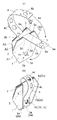
【図2】 図1に示す状態から第1及び第2基布、受け止め基布、第1及び第2補助基布を重ね合わせて接合した状態を示す斜視図
【図3】 図2に示す状態から第1及び第2基布、第1及び第2補助基布を180°反転させ、第1基布の開口に第2基布、第1及び第2補助基布を入れ込んで全体を反転させた状態を示す断面図
【図4】 インフレータにエアバッグを取り付けた状態、及びエアバッグが膨張した状態を示す断面図
【図5】 エアバッグが膨張する状態を示すインストルメントパネルの付近の側面図
【図6】 発明の実施の第1別形態において、展開した状態のエアバッグを1枚の布体から複数枚だけ一体的に裁断する状態を示す平面図
【図7】 発明の実施の第2別形態において、展開した状態のエアバッグを1枚の布体から複数枚だけ一体的に裁断する状態を示す平面図
【図8】 発明の実施の第2別形態において、第1及び第2基布、受け止め基布、第1及び第2補助基布を重ね合わせて接合した状態を示す正面図
【図9】 発明の実施の第3別形態において、展開した状態のエアバッグを1枚の布体から複数枚だけ一体的に裁断する状態を示す平面図
【図10】 発明の実施の第3別形態において、第1基布に補強基布を重ねて接合する状態を示す平面図
【図11】 発明の実施の第4別形態において、展開した状態のエアバッグを1枚の布体から複数枚だけ一体的に裁断する状態を示す平面図
【符号の説明】
1 第1基布
1a 第1基布の前辺部
1b 第1基布の後辺部
1c,1d 第1基布の側辺部
1e 第1基布の取付部
2 第2基布
2a 第2基布の前辺部
2b 第2基布の後辺部
2c,2d 第2基布の側辺部
3 受け止め基布
3a 受け止め基布の上辺部
3b 受け止め基布の下辺部
3c,3d 受け止め基布の側辺部
4,5 補助基布
4b,5b 補助基布の取付部
6 インフレータ[0001]
BACKGROUND OF THE INVENTION
The present invention relates to a vehicle such as a passenger car, a commercial vehicle, and a bus. The front of the seat (in the case of a front seat, in the center of the steering handle, in the instrument panel, etc., in the case of a rear seat, the seat of the front seat) The present invention relates to the configuration of an airbag in an airbag device disposed at a back position or the like.
[0002]
[Prior art]
In general, an airbag as described above is obtained by cutting a base fabric having a predetermined shape from a cloth body and joining the base fabric into a bag shape (sewing by sewing, joining by adhesive, high frequency, ultrasonic wave, heat welding, etc.). It is configured. The airbag is not simply inflated in a round shape. For example, as disclosed in
This is because, when the airbag is inflated, by receiving the occupant with the flat receiving surface, the load when the occupant is received is dispersed without being concentrated on a part of the occupant.
[0003]
[Patent Document 1]
JP 2001-260788 A (FIGS. 3, 4, and 6)
[0004]
[Problems to be solved by the invention]
According to the structure of
Further, according to the structure of
[0005]
When making the receiving surface flat in an air bag, it is necessary to inflate the air bag in a direction slightly different from the direction of the inflator, such as an air bag for a passenger seat, or from the inflator to the passenger The distance may be relatively long.
Further, in order to inflate the airbag so that the receiving surface is flat, it has been proposed to arrange an auxiliary fabric that regulates the shape of the airbag when inflated inside the airbag. The base fabric is joined in the form of a bag with the auxiliary fabric disposed in the bag. In this case, adding an auxiliary fabric to the base fabric may increase the overall joining length when the airbag is configured in a bag shape, and there is room for improvement in terms of reducing production costs.
[0006]
The present invention increases the area of a receiving surface for receiving an occupant in an air bag, and suppresses the possibility that the inflator gas leaks from the joined portion of the air bag and that the expansion of the air bag is delayed. In the case where the airbag needs to be inflated in a direction slightly different from the direction of the inflator or the distance from the inflator to the occupant may be relatively long, the airbag when inflated When the auxiliary cloth which regulates the shape of this is provided, it aims at comprising so that the whole joining length may not become long.
[0007]
[Means for Solving the Problems]
[I]
Claim 1According to the characteristics, in the deployed state (the state before joining), the airbag is the first base fabric and the second base fabric., Receiving base cloth and auxiliary base cloth(One side part of the first and second base fabrics is connected (see, for example, A1 in FIGS. 1 and 11), and one of the receiving base fabrics is provided. The side part is connected to the side part of the first and second base fabrics (see, for example, A2 and A3 in FIGS. 1 and 11).. ReceivingAn auxiliary base fabric is connected to the upper side or the lower side of the anti-stick base fabric (see, for example, A4 and B2 in FIG. 1).).
[0008]
Claim 1According to the characteristics of the airbag in the above stateExampleFor example, as shown in FIGS. 1 and 2 (a), the
[0009]
[II]
According to the description in [I] aboveClaim 1According to the above feature, when the gas in the
[0010]
ThisClaim 1According to the above feature, when the inflator gas flows into the airbag and the airbag is inflated, the first and second base fabrics are extended to the rear of the vehicle body while the second base fabric is lifted. The surface of the receiving base fabric between the rear side portions of the first and second base fabrics is a circle when viewed from the occupant due to the fact that the base fabric is provided with upper and lower side portions, and one and the other side portions. It tends to be a rectangular shape (for example, a rectangular shape) instead of a shape.
[0011]
Claim 1According to the feature, since the auxiliary base fabric is connected to the upper side or the lower side of the receiving base fabric, the state where the central portion side of the receiving base fabric tries to expand is suppressed by the auxiliary base fabric. The lateral side portion of the receiving base fabric that is not connected is in a state of being easily expanded. As a result, the state in which the center side of the receiving base fabric expands and the receiving base fabric becomes spherical toward the passenger is suppressed, and the surface of the receiving base fabric tends to be flat.
[0012]
In this case,Claim 14 (b), for example, when the gas of the
[0013]
[III]
Claim 1According to the above feature, as described in [II] above, when the gas of the inflator flows into the airbag and the airbag is inflated, the first and second base fabrics are lifted while the second base fabric is lifted. Since the direction in which the airbag is inflated is substantially determined by the first and second base fabrics depending on the state of being extended rearward, even if the direction of the inflator is slightly different from the direction in which the airbag is to be inflated, By appropriately setting the first and second base fabrics, the airbag can be accurately inflated in the direction in which it is desired to be inflated.
[0014]
in this case,Claim 1According to the feature, if the distance from the inflator to the occupant is relatively long, the first and second base fabrics may be configured according to this, depending on the lengths of the first and second base fabrics. The position of the receiving base fabric when the airbag is inflated can be set to be appropriate for the occupant.
[0015]
[IV]
Claim 1According to the above feature, the center of the second base fabric is the center of the upper portion of the airbag (see FIG. 4B). In this case, as described in [I] above, one side of the first and second base fabrics is connected, and the other side of the first and second base fabrics are joined.BecauseThe joint portion does not exist in the center of the second base fabric.
[0016]
ThisClaim 1According to the characteristics, when the inflator gas flows into the airbag and the airbag is inflated, the inflator gas hits the center of the upper part of the airbag (the center of the second base fabric) and lifts up. Since there is no joining portion at the center of the upper part of the airbag (the center of the second base fabric), as in
[0017]
[V]
Claim 1According to the characteristics, when the airbag is configured in a bag shape as described in the preceding item [I], the outer peripheral portions (front and rear side portions, side side portions) of the first and second base fabrics are joined, The point which can comprise an airbag in a bag shape, since the one side part of the 1st and 2nd base fabric is connected beforehand, the outer peripheral part (front and back sides of the 1st and 2nd base fabric) Part, side side), and when the outer peripheral parts (front and rear sides, side parts) of the first and second base fabrics are joined, Since the lower side portion and the end portion of the auxiliary base fabric can be joined together, the entire joining length when the airbag is configured in a bag shape can be suppressed to a short one.
According to the features of
by this,Claim 1According to the characteristics, the first base fabric, the second base fabric, Receiving base cloth and auxiliary base clothIt is not necessary to prepare separately and join by sewing or the like to obtain an airbag in a deployed state (state before joining) as described in [I] above.
[0018]
[VI]
Claim 2According to the featuresClaim 1In the same manner as in the above case, the “action” described in the preceding paragraphs [I] to [V] is provided, and in addition to this, the following “action” is provided.
Claim 2According to the above feature, when the first base fabric is provided with an attachment portion attached to the inflator, the auxiliary base fabric is provided with an attachment portion attached to the inflator together with the attachment portion of the first base fabric.
ThisClaim 2According to the feature, since the attachment portion of the first base fabric and the auxiliary base fabric is attached to the inflator, the attachment strength of the airbag to the inflator is higher than when only the attachment portion of the first base fabric is attached to the inflator. Can be a thing.
[0019]
[0020]
DETAILED DESCRIPTION OF THE INVENTION
[1]
FIG. 1 shows a state in which an airbag is deployed (a state before joining), and includes a
[0021]
As shown in FIG. 1, the
[0022]
As shown in FIG. 1, the
[0023]
As shown in FIG. 1, the receiving
[0024]
As shown in FIG. 1, the 1st auxiliary |
[0025]
As shown in FIG. 1, the second
[0026]
[2]
Next, a process of joining the airbag in a deployed state (state before joining) as described in [1] above to a bag shape will be described.
In the airbag in the unfolded state (the state before joining) shown in FIG. 1, as shown in FIG. 2 (a), the first, second, third fold line portions A1, A2, A3 are folded in a mountain, 1 and
[0027]
Accordingly, as shown in FIGS. 2A and 2B and FIG. 3A, the
[0028]
2 (a) and 2 (b) and FIG. 3 (a), the
[0029]
After the joining as described above, the first and
[0030]
Next, as shown in FIG. 3 (c) to FIG. 3 (d), the
[0031]
[3]
The airbag obtained as described in [1] and [2] above is for a passenger seat, and as shown in FIG. 4 (a), the
[0032]
Accordingly, the
[0033]
When the airbag is inflated by the gas of the
[0034]
In this case, when the gas of the
[0035]
As shown in FIGS. 1 and 4 (b), the first and second
[0036]
[First Alternative Embodiment of the Invention]
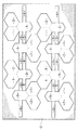
In the above-described [Embodiment of the invention], when only a plurality of airbags in an unfolded state are integrally cut from one
[0037]
When configured as described above, a portion of the
[0038]
[Second Embodiment of the Invention]
In the above-mentioned [Embodiment of the invention] and [First another embodiment of the invention], in the airbag, the first and second
[0039]
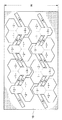
When configured as described above, when a plurality of airbags are integrally cut from one
[0040]
Thereby, the width W of one
[0041]
As described above, the first and second
[0042]
[Third Another Embodiment of the Invention]
In the above-mentioned [Embodiment of the invention] and [First another embodiment of the invention], when the reinforcing
[0043]
As shown in FIG. 9, in a state where only a plurality of airbags in an unfolded state are integrally cut from a
[0044]
If comprised in this way, when the
[0045]
[Fourth Embodiment of the Invention]
In the above-mentioned [Embodiment of the invention] to [Third another embodiment of the invention], the first and second
[0046]
As a result, when a plurality of airbags in a deployed state are integrally cut from a
If comprised as mentioned above, in the sheet |
[0047]
[Fifth Embodiment of the Invention]
In the above-mentioned [Embodiment of the invention] to [Fourth embodiment of the invention], joining is performed by sewing, but an air bag is used as in the case of joining by adhesive, high frequency, ultrasonic wave, heat welding, or the like. Various types of bonding can be employed depending on the material. As the material of the air bag, not only the woven fabric woven with synthetic fibers but also the one configured in the form of a resin sheet can be adopted. These are collectively referred to as the first and
[0048]
In the above-mentioned [Embodiment of the invention] to [Fourth embodiment of the invention], the first and second
The airbag of the present invention can be used not only for a passenger seat but also for a driver seat or for a rear seat.
[0049]
【The invention's effect】
Claim 1According to the features, when the airbag is inflated, the surface of the catching base fabric that catches the occupant can be configured to be a rectangular shape (for example, a rectangular shape) instead of a circular shape as seen from the occupant. The area of the surface of the base fabric can be increased, which is advantageous in that the load when the occupant is received by the inflated airbag is distributed without being concentrated on a part of the occupant. .
[0050]
Claim 1According to the feature of the present invention, by providing the auxiliary base fabric, when the airbag is inflated, the central portion side of the receiving base fabric is inflated so that the receiving base fabric becomes spherical toward the passenger, and the receiving base fabric is suppressed. This is advantageous in that the load when the occupant is received by the inflated airbag is dispersed without being concentrated on a part of the occupant.
[0051]
Claim 1According to the characteristics, by appropriately setting the first and second base fabrics, the airbag can be accurately inflated in the direction in which the airbag is to be inflated so that the position of the receiving base fabric during the inflation is appropriate for the occupant It has become possible to set an air bag suitable for various vehicles.
[0052]
Claim 1According to the feature, since there is no joining portion at the center of the upper portion of the airbag (the center of the second base fabric), when the inflator gas flows into the airbag and the airbag is inflated, the inflator gas is Even if it hits the center of the upper part (the center of the second base fabric) and lifts, there will be no situation where the inflator gas leaks at the joint at the center of the upper part of the airbag. The possibility of developing into a situation where the expansion of the lag is delayed was able to be suppressed.
[0053]
Claim 1According to the feature, when the auxiliary base fabric as described above is provided, the overall joining length when the airbag is configured in a bag shape can be suppressed to a short one. In this way, the production cost could be reduced while improving the performance of the airbag.
Claim 1According to the characteristics, the first base fabric, the second base fabric, Receiving base cloth and auxiliary base clothThis is advantageous in terms of reducing production costs because it is not necessary to prepare the airbag separately and join it by sewing, etc. to obtain an airbag in a deployed state (before joining). It became a thing.
[0054]
Claim 2According to the featuresClaim 1As in the case ofClaim 1In addition to the “effect of the invention”, the following “effect of the invention” is provided.
Claim 2According to the feature of the present invention, the attachment portion of the first base fabric and the auxiliary base fabric is attached to the inflator, and the attachment strength of the airbag to the inflator can be increased, thereby increasing the reliability of the operation of the airbag. I was able to.
[0055]
[Brief description of the drawings]
FIG. 1 is a plan view showing a state in which an airbag is deployed (a state before joining).
FIG. 2 is a perspective view showing a state in which the first and second base fabrics, the receiving base fabric, and the first and second auxiliary base fabrics are overlapped and joined from the state shown in FIG.
3 reverses the first and second base fabrics and the first and second auxiliary base fabrics by 180 ° from the state shown in FIG. 2, and the second base fabric, the first and second auxiliary fabrics are opened in the opening of the first base fabric. Sectional drawing which shows the state which inserted the base fabric and reversed the whole
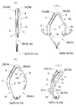
FIG. 4 is a cross-sectional view showing a state where an airbag is attached to an inflator and a state where the airbag is inflated.
FIG. 5 is a side view of the vicinity of the instrument panel showing a state where the airbag is inflated.
FIG. 6 is a plan view showing a state in which a plurality of airbags in a deployed state are integrally cut from a single cloth body in a first alternative embodiment of the invention;
FIG. 7 is a plan view showing a state in which only a plurality of airbags in a deployed state are integrally cut from a single cloth body in a second alternative embodiment of the invention;
FIG. 8 is a front view showing a state in which the first and second base fabrics, the receiving base fabric, and the first and second auxiliary base fabrics are overlapped and joined in the second alternative embodiment of the invention.
FIG. 9 is a plan view showing a state in which only a plurality of airbags in a deployed state are integrally cut from one cloth body in a third alternative embodiment of the invention;
FIG. 10 is a plan view showing a state in which the reinforcing base fabric is overlapped and joined to the first base fabric in a third alternative embodiment of the invention;
FIG. 11 is a plan view showing a state in which only a plurality of airbags in a deployed state are integrally cut from one cloth body in a fourth alternative embodiment of the invention;
[Explanation of symbols]
1 First fabric
1a Front side of the first base fabric
1b Rear side of the first base fabric
1c, 1d Side edges of the first base fabric
1e First base fabric attachment
2 Second base fabric
2a Front side of the second base fabric
2b Rear side of the second base fabric
2c, 2d Side edges of the second base fabric
3 receiving base fabric
3a Upper side of the receiving base fabric
3b Lower side of receiving base fabric
3c, 3d Side edges of receiving base fabric
4,5 Auxiliary base fabric
4b, 5b Auxiliary base attachment
6 Inflator
Claims (2)
膨張時の車体前方側に対応する前辺部と、膨張時の車体後方側に対応する後辺部と、膨張時の車体右方及び左方側に対応する一方及び他方の側辺部とを備えた第2基布、
膨張時の車体上方側に対応する上辺部と、膨張時の車体下方側に対応する下辺部と、膨張時の車体右方及び左方側に対応する一方及び他方の側辺部とを備えた乗員の受け止め基布を備えて、
前記第1基布の一方の側辺部と第2基布の一方の側辺部とが接続され、前記受け止め基布の一方の側辺部と第1及び第2基布の一方の側辺部とが接続され、前記受け止め基布の上辺部又は下辺部と補助基布とが接続されて、前記第1基布、第2基布、受け止め基布及び補助基布を1枚の布体により一体的に構成すると共に、
前記第1基布の後辺部と前記受け止め基布の下辺部とが接合され、前記第2基布の後辺部と前記受け止め基布の上辺部とが接合され、前記第1、第2、受け止め基布の他方の側辺部が接合されて、前記第1及び第2基布の前辺部と前記補助基布の端部とが接合されてあるエアバッグ。A front side corresponding to the front side of the vehicle body at the time of expansion, a rear side portion corresponding to the rear side of the vehicle body at the time of expansion, one and the other side sides corresponding to the right and left sides of the vehicle body at the time of expansion, A first base fabric comprising an inflator mounting portion;
A front side portion corresponding to the front side of the vehicle body when inflated, a rear side portion corresponding to the rear side of the vehicle body when expanded, and one and other side portions corresponding to the right and left sides of the vehicle body when expanded. A second base fabric,
An upper side corresponding to the upper side of the vehicle body when expanded, a lower side corresponding to the lower side of the vehicle body when expanded, and one and the other side portions corresponding to the right and left sides of the vehicle body when expanded Equipped with an occupant receiving base fabric,
One side of the first base fabric and one side of the second base fabric are connected, and one side of the receiving base fabric and one side of the first and second base fabrics. A first base fabric, a second base fabric, a receiving base fabric and an auxiliary base fabric are connected to each other by connecting an upper base portion or a lower side portion of the receiving base fabric with an auxiliary base fabric. And integrated into
The rear side of the first base fabric and the lower side of the receiving base fabric are joined, the rear side of the second base fabric and the upper side of the receiving base fabric are joined, and the first and second An airbag in which the other side portion of the receiving base fabric is joined and the front side portions of the first and second base fabrics and the end portion of the auxiliary base fabric are joined .
Priority Applications (1)
| Application Number | Priority Date | Filing Date | Title |
|---|---|---|---|
| JP2002344208A JP4145128B2 (en) | 2002-02-08 | 2002-11-27 | Airbag |
Applications Claiming Priority (3)
| Application Number | Priority Date | Filing Date | Title |
|---|---|---|---|
| JP2002032177 | 2002-02-08 | ||
| JP2002-32177 | 2002-02-08 | ||
| JP2002344208A JP4145128B2 (en) | 2002-02-08 | 2002-11-27 | Airbag |
Publications (2)
| Publication Number | Publication Date |
|---|---|
| JP2003300446A JP2003300446A (en) | 2003-10-21 |
| JP4145128B2 true JP4145128B2 (en) | 2008-09-03 |
Family
ID=29404987
Family Applications (1)
| Application Number | Title | Priority Date | Filing Date |
|---|---|---|---|
| JP2002344208A Expired - Fee Related JP4145128B2 (en) | 2002-02-08 | 2002-11-27 | Airbag |
Country Status (1)
| Country | Link |
|---|---|
| JP (1) | JP4145128B2 (en) |
Families Citing this family (3)
| Publication number | Priority date | Publication date | Assignee | Title |
|---|---|---|---|---|
| JP2006051884A (en) * | 2004-08-11 | 2006-02-23 | Autoliv Development Ab | Airbag device |
| JP5195400B2 (en) | 2008-12-24 | 2013-05-08 | タカタ株式会社 | Air bag and air bag device |
| JP5344971B2 (en) * | 2009-04-07 | 2013-11-20 | タカタ株式会社 | Air bag and air bag device |
Family Cites Families (11)
| Publication number | Priority date | Publication date | Assignee | Title |
|---|---|---|---|---|
| JP2673404B2 (en) * | 1992-12-24 | 1997-11-05 | 東洋ゴム工業株式会社 | Base fabric for airbag and method of manufacturing airbag for passenger seat using the base fabric |
| JP2673405B2 (en) * | 1993-01-27 | 1997-11-05 | 東洋ゴム工業株式会社 | Passenger airbag |
| CN1117282A (en) * | 1993-02-02 | 1996-02-21 | 约翰·堡格 | Airbag and manufacturing method therefor |
| JPH06239191A (en) * | 1993-02-18 | 1994-08-30 | Toyoda Gosei Co Ltd | Air bag for assistant's seat |
| JP3800702B2 (en) * | 1997-01-28 | 2006-07-26 | トヨタ紡織株式会社 | Airbag |
| JP3340354B2 (en) * | 1997-08-04 | 2002-11-05 | 日本プラスト株式会社 | Airbag |
| JPH11129843A (en) * | 1997-11-04 | 1999-05-18 | Nippon Plast Co Ltd | Air bag |
| JP2000159045A (en) * | 1998-11-27 | 2000-06-13 | Nippon Plast Co Ltd | Air bag and its manufacture |
| JP2000190797A (en) * | 1998-12-25 | 2000-07-11 | Toyoda Gosei Co Ltd | Air bag |
| JP4608072B2 (en) * | 2000-02-25 | 2011-01-05 | タカタ株式会社 | Airbag device |
| JP4435961B2 (en) * | 2000-09-28 | 2010-03-24 | 日本プラスト株式会社 | Automotive airbag equipment |
-
2002
- 2002-11-27 JP JP2002344208A patent/JP4145128B2/en not_active Expired - Fee Related
Also Published As
| Publication number | Publication date |
|---|---|
| JP2003300446A (en) | 2003-10-21 |
Similar Documents
| Publication | Publication Date | Title |
|---|---|---|
| US7735856B2 (en) | Air-bag | |
| JP4743014B2 (en) | Passenger airbag | |
| JP3900008B2 (en) | Airbag | |
| US9290149B2 (en) | Airbag apparatus for a front passenger seat | |
| KR20080070003A (en) | Flexible housing for an airbag module | |
| JP7188153B2 (en) | passenger airbag | |
| JP3160630B2 (en) | Passenger airbag | |
| JP2000016210A (en) | Airbag | |
| WO2010008060A1 (en) | Vehicle airbag and method of manufacturing the same | |
| JP5206722B2 (en) | Airbag device | |
| JP4145128B2 (en) | Airbag | |
| JP2021037896A (en) | Airbag for front passenger seat | |
| JP5632814B2 (en) | Airbag device | |
| JP5206708B2 (en) | Airbag device for passenger seat | |
| JP2009506938A (en) | Air bag for protecting knee area of vehicle occupant | |
| JP3520047B2 (en) | Airbag modules, especially front passenger airbag modules | |
| JP3769835B2 (en) | Airbag device for vehicle | |
| JP5206707B2 (en) | Airbag device for passenger seat | |
| JP2013154830A (en) | Airbag device for steering wheel | |
| JP6973345B2 (en) | Passenger seat airbag | |
| JP7439787B2 (en) | Airbag | |
| JP2001138848A (en) | Air bag | |
| JP2000153742A (en) | Manufacturing method of vehicle airbag | |
| JPH0633756U (en) | Vehicle airbag with vent holes | |
| JP2021020654A (en) | Air bag device for front passenger seat |
Legal Events
| Date | Code | Title | Description |
|---|---|---|---|
| A621 | Written request for application examination |
Free format text: JAPANESE INTERMEDIATE CODE: A621 Effective date: 20050901 |
|
| A131 | Notification of reasons for refusal |
Free format text: JAPANESE INTERMEDIATE CODE: A131 Effective date: 20071129 |
|
| A977 | Report on retrieval |
Free format text: JAPANESE INTERMEDIATE CODE: A971007 Effective date: 20071203 |
|
| A521 | Written amendment |
Free format text: JAPANESE INTERMEDIATE CODE: A523 Effective date: 20080122 |
|
| A131 | Notification of reasons for refusal |
Free format text: JAPANESE INTERMEDIATE CODE: A131 Effective date: 20080313 |
|
| A521 | Written amendment |
Free format text: JAPANESE INTERMEDIATE CODE: A523 Effective date: 20080417 |
|
| TRDD | Decision of grant or rejection written | ||
| A01 | Written decision to grant a patent or to grant a registration (utility model) |
Free format text: JAPANESE INTERMEDIATE CODE: A01 Effective date: 20080605 |
|
| A01 | Written decision to grant a patent or to grant a registration (utility model) |
Free format text: JAPANESE INTERMEDIATE CODE: A01 |
|
| A61 | First payment of annual fees (during grant procedure) |
Free format text: JAPANESE INTERMEDIATE CODE: A61 Effective date: 20080617 |
|
| R150 | Certificate of patent or registration of utility model |
Free format text: JAPANESE INTERMEDIATE CODE: R150 |
|
| FPAY | Renewal fee payment (event date is renewal date of database) |
Free format text: PAYMENT UNTIL: 20110627 Year of fee payment: 3 |
|
| FPAY | Renewal fee payment (event date is renewal date of database) |
Free format text: PAYMENT UNTIL: 20110627 Year of fee payment: 3 |
|
| FPAY | Renewal fee payment (event date is renewal date of database) |
Free format text: PAYMENT UNTIL: 20130627 Year of fee payment: 5 |
|
| LAPS | Cancellation because of no payment of annual fees |