JP5195400B2 - Air bag and air bag device - Google Patents
Air bag and air bag device Download PDFInfo
- Publication number
- JP5195400B2 JP5195400B2 JP2008327977A JP2008327977A JP5195400B2 JP 5195400 B2 JP5195400 B2 JP 5195400B2 JP 2008327977 A JP2008327977 A JP 2008327977A JP 2008327977 A JP2008327977 A JP 2008327977A JP 5195400 B2 JP5195400 B2 JP 5195400B2
- Authority
- JP
- Japan
- Prior art keywords
- airbag
- regulating member
- sub
- occupant
- restricting
- Prior art date
- Legal status (The legal status is an assumption and is not a legal conclusion. Google has not performed a legal analysis and makes no representation as to the accuracy of the status listed.)
- Expired - Fee Related
Links
- 230000001105 regulatory effect Effects 0.000 claims description 160
- 239000002759 woven fabric Substances 0.000 claims description 39
- 239000004744 fabric Substances 0.000 claims description 21
- 230000033228 biological regulation Effects 0.000 claims description 14
- 230000002093 peripheral effect Effects 0.000 claims description 8
- 230000003014 reinforcing effect Effects 0.000 claims description 4
- 238000005192 partition Methods 0.000 claims description 3
- 230000000452 restraining effect Effects 0.000 claims description 2
- 238000000034 method Methods 0.000 description 15
- 238000003780 insertion Methods 0.000 description 5
- 230000037431 insertion Effects 0.000 description 5
- 229920006015 heat resistant resin Polymers 0.000 description 4
- 238000009958 sewing Methods 0.000 description 4
- 238000009941 weaving Methods 0.000 description 3
- 101001108245 Cavia porcellus Neuronal pentraxin-2 Proteins 0.000 description 2
- 238000013459 approach Methods 0.000 description 2
- 239000011248 coating agent Substances 0.000 description 2
- 238000000576 coating method Methods 0.000 description 2
- 239000000725 suspension Substances 0.000 description 2
- 206010037660 Pyrexia Diseases 0.000 description 1
- 230000015572 biosynthetic process Effects 0.000 description 1
- 230000007423 decrease Effects 0.000 description 1
- 238000002474 experimental method Methods 0.000 description 1
- 230000000717 retained effect Effects 0.000 description 1
- 230000008961 swelling Effects 0.000 description 1
- 238000012360 testing method Methods 0.000 description 1
Images


Classifications
-
- B—PERFORMING OPERATIONS; TRANSPORTING
- B60—VEHICLES IN GENERAL
- B60R—VEHICLES, VEHICLE FITTINGS, OR VEHICLE PARTS, NOT OTHERWISE PROVIDED FOR
- B60R21/00—Arrangements or fittings on vehicles for protecting or preventing injuries to occupants or pedestrians in case of accidents or other traffic risks
- B60R21/02—Occupant safety arrangements or fittings, e.g. crash pads
- B60R21/16—Inflatable occupant restraints or confinements designed to inflate upon impact or impending impact, e.g. air bags
- B60R21/23—Inflatable members
- B60R21/231—Inflatable members characterised by their shape, construction or spatial configuration
- B60R21/2334—Expansion control features
- B60R21/2338—Tethers
-
- B—PERFORMING OPERATIONS; TRANSPORTING
- B60—VEHICLES IN GENERAL
- B60R—VEHICLES, VEHICLE FITTINGS, OR VEHICLE PARTS, NOT OTHERWISE PROVIDED FOR
- B60R21/00—Arrangements or fittings on vehicles for protecting or preventing injuries to occupants or pedestrians in case of accidents or other traffic risks
- B60R21/02—Occupant safety arrangements or fittings, e.g. crash pads
- B60R21/16—Inflatable occupant restraints or confinements designed to inflate upon impact or impending impact, e.g. air bags
- B60R21/23—Inflatable members
- B60R21/231—Inflatable members characterised by their shape, construction or spatial configuration
- B60R21/2334—Expansion control features
- B60R21/2338—Tethers
- B60R2021/23382—Internal tether means
- B60R2021/23384—Internal tether means having ends which are movable or detachable during deployment
-
- B—PERFORMING OPERATIONS; TRANSPORTING
- B60—VEHICLES IN GENERAL
- B60R—VEHICLES, VEHICLE FITTINGS, OR VEHICLE PARTS, NOT OTHERWISE PROVIDED FOR
- B60R21/00—Arrangements or fittings on vehicles for protecting or preventing injuries to occupants or pedestrians in case of accidents or other traffic risks
- B60R21/02—Occupant safety arrangements or fittings, e.g. crash pads
- B60R21/16—Inflatable occupant restraints or confinements designed to inflate upon impact or impending impact, e.g. air bags
- B60R21/20—Arrangements for storing inflatable members in their non-use or deflated condition; Arrangement or mounting of air bag modules or components
- B60R21/201—Packaging straps or envelopes for inflatable members
-
- B—PERFORMING OPERATIONS; TRANSPORTING
- B60—VEHICLES IN GENERAL
- B60R—VEHICLES, VEHICLE FITTINGS, OR VEHICLE PARTS, NOT OTHERWISE PROVIDED FOR
- B60R21/00—Arrangements or fittings on vehicles for protecting or preventing injuries to occupants or pedestrians in case of accidents or other traffic risks
- B60R21/02—Occupant safety arrangements or fittings, e.g. crash pads
- B60R21/16—Inflatable occupant restraints or confinements designed to inflate upon impact or impending impact, e.g. air bags
- B60R21/23—Inflatable members
- B60R21/237—Inflatable members characterised by the way they are folded
-
- B—PERFORMING OPERATIONS; TRANSPORTING
- B60—VEHICLES IN GENERAL
- B60R—VEHICLES, VEHICLE FITTINGS, OR VEHICLE PARTS, NOT OTHERWISE PROVIDED FOR
- B60R21/00—Arrangements or fittings on vehicles for protecting or preventing injuries to occupants or pedestrians in case of accidents or other traffic risks
- B60R21/02—Occupant safety arrangements or fittings, e.g. crash pads
- B60R21/16—Inflatable occupant restraints or confinements designed to inflate upon impact or impending impact, e.g. air bags
- B60R21/23—Inflatable members
- B60R21/239—Inflatable members characterised by their venting means
Landscapes
- Engineering & Computer Science (AREA)
- Mechanical Engineering (AREA)
- Air Bags (AREA)
Description
本発明は、エアバッグ膨張時に、該エアバッグの乗員対向面のうち乗員の頭部と対面する頭部対面部に、乗員側から凹陥する凹部が形成されるように構成されたエアバッグに係り、特に、該頭部対面部の乗員側への膨出を規制する規制部材が設けられ、エアバッグ膨張時には、この規制部材によって該頭部対面部の乗員側への膨出が規制されることにより、前記凹部が形成されるように構成されたエアバッグに関する。また、本発明は、このエアバッグを備えたエアバッグ装置に関する。 The present invention relates to an airbag configured such that, when the airbag is inflated, a concave portion that is recessed from the occupant side is formed in a head-facing portion that faces the occupant's head among the occupant-facing surfaces of the airbag. In particular, a restricting member that restricts the bulging of the head-to-face portion toward the occupant side is provided, and when the airbag is inflated, the restricting member restricts the bulging of the head-to-face portion toward the occupant side. Thus, the present invention relates to an airbag configured to form the recess. Moreover, this invention relates to the airbag apparatus provided with this airbag.
特に、本発明は、車両の助手席用として好適なエアバッグ及びエアバッグ装置に関する。 In particular, the present invention relates to an airbag and an airbag apparatus suitable for a passenger seat of a vehicle.
なお、本発明において、AF05型乗員ダミーとは、米国法規に規定されている小柄な5パーセンタイル成人女性を模した車両衝突実験用乗員ダミーをいい、AM50型乗員ダミーとは、それよりも大柄な50パーセンタイル成人男性を模した車両衝突実験用乗員ダミーをいう。 In the present invention, the AF05 type occupant dummy refers to a vehicle collision test occupant dummy imitating a small five-percentile adult woman prescribed in US law, and the AM50 type occupant dummy is larger than that. An occupant dummy for vehicle collision experiments that imitates a 50th percentile adult male.
また、本発明において、小柄な乗員とは、このAF05型乗員ダミーに対応する体格を有した乗員をいい、大柄な乗員とは、AM50型乗員ダミーに対応する体格を有した乗員をいう。 In the present invention, a small passenger means an occupant having a physique corresponding to this AF05 type occupant dummy, and a large occupant means an occupant having a physique corresponding to an AM50 type occupant dummy.
第25図に、一般的な助手席用エアバッグ装置の構成を示す。 FIG. 25 shows the structure of a general passenger airbag device.
助手席用エアバッグ装置100は、エアバッグ101と、ケース102と、インフレータ103とを有している。このエアバッグ101は、折り畳まれてケース102内に収容され、インフレータ103によって膨張される。このケース102は、上面が開放した容器であり、その上面はインストルメントパネル104によって覆われている。インストルメントパネル104の上方にはウィンドシールド105が存在する。 The passenger seat airbag device 100 includes an airbag 101, a case 102, and an inflator 103. The airbag 101 is folded and accommodated in the case 102 and inflated by the inflator 103. The case 102 is a container having an open upper surface, and the upper surface is covered with an instrument panel 104. A windshield 105 exists above the instrument panel 104.
エアバッグ101は、インフレータ103からガスが供給されることによりインストルメントパネル104の上面から該インストルメントパネル104とウィンドシールド105との間及び助手席前方の空間を埋めるように膨張する。この膨張したエアバッグ101の車体後方側の面が助手席乗員に対面する乗員対向面101Fとなる。 When the gas is supplied from the inflator 103, the airbag 101 is inflated from the upper surface of the instrument panel 104 so as to fill a space between the instrument panel 104 and the windshield 105 and in front of the passenger seat. A surface on the rear side of the vehicle body of the inflated airbag 101 is an occupant facing surface 101F that faces the passenger on the passenger seat.
小柄な乗員は、座席をその後退限よりも前方へスライドさせて着座していることがある。これに対し、大柄な乗員は、座席を前方へスライドさせることなく着座していることが多い。 A small occupant may be seated by sliding the seat forward rather than the retreat limit. On the other hand, large passengers often sit without sliding the seat forward.
一般的に、エアバッグ101は、乗員が座席を前方へスライドさせることなく着座している場合でも、膨張完了時に乗員対向面101Fがこの乗員の頭部に十分に接近しうる容積を有している。 Generally, even when the occupant is seated without sliding the seat forward, the airbag 101 has a volume that allows the occupant facing surface 101F to sufficiently approach the occupant's head when inflation is completed. Yes.
しかしながら、乗員が座席を前方へスライドさせて着座している場合には、第25図に示すように、乗員側へ膨出途中の乗員対向面101Fに乗員頭部が接触する可能性があり、この場合、乗員頭部に乗員対向面101Fが強く接触するおそれがある。 However, when the occupant is seated by sliding the seat forward, as shown in FIG. 25, the occupant head may come into contact with the occupant facing surface 101F in the middle of bulging toward the occupant, In this case, the occupant facing surface 101F may come into strong contact with the occupant head.
特開2001−233157号公報には、エアバッグ膨張時に、該エアバッグの乗員対向面のうち乗員の頭部と対面する位置に凹部が形成されるように構成されたエアバッグが記載されている。同号公報では、エアバッグ膨張時において、この凹部の最深部が乗員の顎部よりも下方に位置し、この凹部の最深部よりも上側の斜面が乗員頭部(顔面)に対面するように構成されている。 Japanese Patent Application Laid-Open No. 2001-233157 describes an airbag configured such that, when the airbag is inflated, a recess is formed at a position facing the occupant's head on the occupant-facing surface of the airbag. . In the publication, when the airbag is inflated, the deepest part of the recess is positioned below the occupant's jaw, and the slope above the deepest part of the recess faces the occupant's head (face). It is configured.
エアバッグ膨張時において、この凹部の最深部よりも上側の斜面は、エアバッグ上部側ほど車両後方となるように傾斜(オーバーハング)している。そのため、小柄な乗員が座席を前方にスライドさせて着座している場合でも、大柄な乗員が座席を前方にスライドさせずに着座している場合でも、エアバッグ膨張時には、この凹部の最深部よりも上側の斜面と乗員頭部との間には、同程度の距離が確保される。 When the airbag is inflated, the slope above the deepest part of the recess is inclined (overhangs) so that the upper part of the airbag is closer to the rear of the vehicle. Therefore, even when a small occupant is seated by sliding the seat forward, or when a large occupant is seated without sliding the seat forward, when the airbag is inflated, the deepest part of this recess The same distance is ensured between the upper slope and the passenger's head.
これにより、小柄な乗員が座席を前方へスライドさせて着座している場合に、乗員頭部に膨出途中の乗員対向面が強く接触することが防止される。 Thereby, when a small occupant is seated by sliding the seat forward, it is possible to prevent the occupant facing surface in the middle of the bulge from coming into strong contact with the occupant head.
同号公報には、エアバッグ内に、該エアバッグの乗員対向面と反乗員側とを連結する吊り紐を設け、エアバッグ膨張時に、この吊り紐によって乗員対向面が部分的にエアバッグ内に引っ張られることにより、該乗員対向面に凹部が形成されるように構成することが記載されている。
上記特開2001−233157号公報においては、小柄な乗員が座席を前方へスライドさせずに着座している場合には、膨張したエアバッグの乗員対向面と乗員頭部との間の距離が大きくなる。 In JP-A-2001-233157, when a small occupant is seated without sliding the seat forward, the distance between the occupant facing surface of the inflated airbag and the occupant head is large. Become.
また、一般的に、ウィンドシールドは、第25図の如く上端側ほど車体後方側となるように傾斜しているので、エアバッグは、膨張したときに、このウィンドシールドの傾斜に沿ってその上部側ほど車体前後方向の厚みが小さくなる膨張形状を有している。そのため、吊り紐で乗員対向面の乗員側への膨出を規制すると、膨張したエアバッグの上部側の車体前後方向の厚みが不足するおそれがある。 In general, the windshield is inclined so that the upper end side is the rear side of the vehicle body as shown in FIG. 25. Therefore, when the airbag is inflated, the upper part of the windshield is arranged along the inclination of the windshield. It has an expanded shape in which the thickness in the longitudinal direction of the vehicle body decreases toward the side. Therefore, if the suspending of the occupant-facing surface to the occupant side is restricted by the hanging strap, there is a risk that the thickness of the upper part of the inflated airbag in the longitudinal direction of the vehicle body will be insufficient.
本発明は、乗員が座席を前方にスライドさせて着座している場合にも、座席を前方にスライドさせずに着座している場合にも、効果的に乗員頭部を拘束することが可能なエアバッグと、このエアバッグを備えたエアバッグ装置とを提供することを目的とする。 The present invention can effectively restrain the occupant's head even when the occupant is seated by sliding the seat forward or when the seat is seated without sliding the seat forward. An object is to provide an airbag and an airbag apparatus including the airbag.
本発明(請求項1)のエアバッグは、乗員を拘束するためのエアバッグであって、該エアバッグは、該エアバッグを形成すると共に、エアバッグ膨張時に乗員の頭部と対面する頭部対面部を有する乗員対向面を備えたパネルと、エアバッグ膨張時に該頭部対面部に形成される凹部と、該頭部対面部の乗員側への膨出を規制するための規制部材であって、エアバッグ膨張時に該頭部対面部の乗員側への膨出を規制することにより該凹部を形成する規制部材と、エアバッグ膨張時に、該凹部よりも下方に位置する該乗員対向面の下部を連結するためのものであり、該規制部材よりも長さが短い副規制部材とを備えており、該規制部材及び副規制部材は帯状のものであり、該規制部材は、エアバッグが膨張を開始してから所定時間経過後に規制を解除するように構成されており、該副規制部材は、エアバッグ膨張時において、該規制部材が規制を解除する前に破断するように構成されており、該規制部材は、エアバッグ膨張時において、該エアバッグ内を、該規制部材よりも該エアバッグの上端側の上部室と、該規制部材よりも該エアバッグの下端側の下部室とに仕切るように延在しており、該エアバッグは、該上部室内にインフレータからのガスが供給されるように構成されており、該エアバッグは、折り畳まれた状態でエアバッグ装置に設置されるものであり、該エアバッグは、折り畳まれた状態にあっては、その膨張時の上半側の折り畳み体が下半側の折り畳み体の上に載置されるように折り畳まれており、該エアバッグは、膨張時には、該乗員対向面のうち該頭部対面部よりも上側の部分が該下部よりも早期に乗員側へ膨張するものとなっており、前記規制部材は、エアバッグ内部に配置され、該頭部対面部と、エアバッグの膨張時の反乗員側とを連結しており、該規制部材は、エアバッグが膨張を開始してから前記所定時間経過後に該規制部材に負荷される張力(以下、規制部材張力という。)により破断して該頭部対面部と該反乗員側との連結を解除するように構成されており、該規制部材に脆弱部(以下、規制部材脆弱部という。)が設けられており、該規制部材に該規制部材張力が負荷されたときには、該規制部材脆弱部において該規制部材が破断するように構成されており、該規制部材に開口(以下、規制部材開口という。)が設けられており、該規制部材開口の周縁部が該規制部材脆弱部となっており、該規制部材開口は、該規制部材をその厚み方向(以下、規制部材厚み方向という。)に貫通したものであり、該規制部材の該規制部材張力方向及び該規制部材厚み方向の双方と直交する方向(以下、規制部材幅方向という。)の両端側の各側辺と該規制部材開口との間がそれぞれ該規制部材脆弱部となっており、前記副規制部材に脆弱部(以下、副規制部材脆弱部という。)が設けられており、エアバッグが膨張を開始してから前記規制部材が規制を解除する前に、該副規制部材に負荷された張力(以下、副規制部材張力という。)により、該副規制部材脆弱部において該副規制部材が破断するように構成されており、該副規制部材に開口(以下、副規制部材開口という。)が設けられており、該副規制部材開口の周縁部が該副規制部材脆弱部となっており、該副規制部材開口は、該副規制部材をその厚み方向(以下、副規制部材厚み方向という。)に貫通したものであり、該副規制部材の該副規制部材張力方向及び該副規制部材厚み方向の双方と直交する方向(以下、副規制部材幅方向という。)の両端側の各側辺と該副規制部材開口との間がそれぞれ該副規制部材脆弱部となっており、該副規制部材幅方向における該副規制部材脆弱部の幅は、該規制部材幅方向における該規制部材脆弱部の幅よりも小さなものとなっており、該副規制部材張力方向における該副規制部材開口の幅は、該規制部材張力方向における該規制部材開口の幅よりも小さなものとなっており、これにより、エアバッグが膨張を開始してから該規制部材脆弱部が該規制部材張力により破断する前に、該副規制部材脆弱部が該副規制部材張力により破断するように構成されていることを特徴とするものである。 The airbag of the present invention (Claim 1) is an airbag for restraining an occupant, and the airbag forms the airbag and faces the occupant's head when the airbag is inflated. A panel having an occupant-facing surface having a facing portion, a recess formed in the head-facing portion when the airbag is inflated, and a regulating member for regulating bulging of the head-facing portion toward the occupant side. A restricting member that forms the recess by restricting the bulging of the head-to-face portion toward the occupant when the airbag is inflated, and an occupant-facing surface that is positioned below the recess when the airbag is inflated. And a sub-regulating member having a length shorter than that of the regulating member. The regulating member and the sub-regulating member are band-shaped, and the regulating member includes an airbag. The regulation is released after a predetermined time has elapsed since the start of inflation The sub-regulating member is configured to be broken before the regulating member releases the regulation when the airbag is inflated, and the regulating member is configured to be used when the airbag is inflated. The airbag extends so as to partition into an upper chamber on the upper end side of the airbag with respect to the regulating member and a lower chamber on the lower end side of the airbag with respect to the regulating member. Is configured so that gas from the inflator is supplied into the upper chamber, and the airbag is installed in an airbag device in a folded state, and the airbag is folded. In the state, the folded body on the upper half side during the inflation is folded so as to be placed on the folded body on the lower half side. Above the head-to-face part Parts has become a that expands toward the occupant earlier than the lower portion, the regulating member is disposed inside the airbag, and a head portion facing section, and a side opposite the occupant upon inflation of the air bag The regulating member is ruptured by a tension (hereinafter referred to as regulating member tension) applied to the regulating member after the predetermined time has elapsed since the airbag started to inflate, and the head-facing portion And the non-occupant side are released, and the restricting member is provided with a fragile portion (hereinafter referred to as a restricting member fragile portion), and the restricting member tension is applied to the restricting member. When this is done, the restricting member is configured to break at the restricting member weakened portion, and the restricting member is provided with an opening (hereinafter referred to as restricting member opening), and the peripheral portion of the restricting member opening Is a fragile part of the regulating member, and The restricting member opening refers to the restricting member in the thickness direction (hereinafter referred to as restricting member thickness direction). ) And both sides of the restricting member in the direction perpendicular to both the restricting member tension direction and the restricting member thickness direction (hereinafter referred to as restricting member width direction) and the restricting member. Between the openings, the restricting member is fragile, and the sub-regulating member is provided with a fragile portion (hereinafter referred to as a sub-regulating member fragile portion). Before the restricting member releases the restriction, the sub restricting member is broken at the weak portion of the sub restricting member by the tension applied to the sub restricting member (hereinafter referred to as sub restricting member tension). The sub-regulator member is provided with an opening (hereinafter referred to as a sub-regulator member opening), the peripheral edge of the sub-regulator member opening is the sub-regulator member weakened portion, and the sub-regulator member opening is The sub-regulator member in the thickness direction (hereinafter referred to as It is penetrated in the member thickness direction.) Both ends of a direction (hereinafter referred to as a sub-regulating member width direction) perpendicular to both the sub-regulating member tension direction and the sub-regulating member thickness direction of the sub-regulating member. Each side of the side and the opening of the sub-regulator member is the sub-regulator member weakened portion, and the width of the sub-regulator member weakened portion in the sub-regulator member width direction is The width of the sub-regulating member opening in the direction of tension of the sub-regulating member is smaller than the width of the opening of the regulating member in the direction of tension of the regulating member. Thus, the auxiliary restricting member weakened portion is broken by the sub-regulating member tension before the restricting member weakened portion is broken by the restricting member tension after the airbag starts to inflate. characterized in that it has It is intended to.
請求項2のエアバッグは、請求項1において、前記所定時間は、エアバッグが膨張を開始してから15〜40m秒であることを特徴とするものである。 According to a second aspect of the present invention, in the first aspect, the predetermined time is 15 to 40 milliseconds after the airbag starts to inflate.
請求項3のエアバッグは、請求項1又は2において、前記規制部材脆弱部は、エアバッグ膨張時における前記規制部材の前記反乗員側の端部から210〜240mm離隔していることを特徴とするものである。
Airbag according to claim 3, in
請求項4のエアバッグは、請求項1ないし3のいずれか1項において、前記規制部材は織布よりなり、該規制部材のうち少なくとも前記規制部材脆弱部において、該織布の糸目方向が前記規制部材張力方向に対し斜交方向となっていることを特徴とするものである。
The airbag according to claim 4 is the airbag according to any one of
請求項5のエアバッグは、請求項4において、少なくとも前記規制部材のエアバッグ膨張時における反乗員側の端部及びその近傍においては、前記織布の糸目方向が前記規制部材張力方向と略平行方向となっていることを特徴とするものである。 The airbag according to claim 5 is the airbag according to claim 4 , wherein the yarn direction of the woven fabric is substantially parallel to the tension direction of the regulating member at least at the end portion on the side opposite to the occupant when the airbag of the regulating member is inflated. It is characterized by a direction.
請求項6のエアバッグは、請求項1ないし5のいずれか1項において、前記副規制部材は、エアバッグが膨張を開始してから10〜30m秒後に破断するように構成されていることを特徴とするものである。
The airbag according to
請求項7のエアバッグは、請求項1ないし6のいずれか1項において、前記副規制部材脆弱部は、エアバッグ膨張時における前記副規制部材の前記反乗員側の端部から190〜220mm離隔していることを特徴とするものである。
Airbag according to
請求項8のエアバッグは、請求項1ないし7のいずれか1項において、前記副規制部材は織布よりなり、該副規制部材のうち少なくとも前記副規制部材脆弱部において、該織布の糸目方向が前記副規制部材張力方向に対し斜交方向となっていることを特徴とするものである。
The airbag according to claim 8 is the airbag according to any one of
請求項9のエアバッグは、請求項8において、少なくとも前記副規制部材のエアバッグ膨張時における反乗員側の端部及びその近傍においては、前記織布の糸目方向が前記副規制部材張力方向と略平行方向となっていることを特徴とするものである。
請求項10のエアバッグは、請求項1ないし9のいずれか1項において、前記規制部材は、前記エアバッグの前記乗員対向面と反対側の前端部に連結されており、且つ、該規制部材の前端側を所定長さにわたって該エアバッグの折り畳み時における該前端部の下面側に折り返した折り返し部を有しており、該折り返し部の折り目は車体前方側を向いていることを特徴とするものである。
請求項11のエアバッグは、請求項1ないし10のいずれか1項において、前記規制部材は、一端が前記乗員対向面の前記凹部に接続された第1ハーフパネルと、一端が前記エアバッグの該乗員対向面と反対側の前端部に接続された第2ハーフパネルとを備え、該第1ハーフパネルと第2ハーフパネルとの他端同士が結合されたものとなっており、該第2ハーフパネルは、該第1ハーフパネルに比べて破断強度が高いものとなっていることを特徴とするものである。
請求項12のエアバッグは、請求項1ないし11のいずれか1項において、前記副規制部材は、一端が前記乗員対向面の前記下部に接続された第1ハーフパネルと、一端が前記エアバッグの該乗員対向面と反対側の前端部に接続された第2ハーフパネルとを備え、該第1ハーフパネルと第2ハーフパネルとの他端同士が結合されたものとなっており、該第2ハーフパネルは、該第1ハーフパネルに比べて破断強度が高いものとなっていることを特徴とするものである。
請求項13のエアバッグは、請求項1ないし12のいずれか1項において、前記エアバッグは、さらに、前記乗員対向面と反対側の前端部と、該エアバッグの該前端部における前記パネルの表面に取り付けられた補強布とを備えていることを特徴とするものである。
An airbag according to a ninth aspect is the airbag according to the eighth aspect , wherein the yarn direction of the woven fabric is the tension direction of the auxiliary regulating member at least at the end on the side opposite to the occupant when the airbag of the auxiliary regulating member is inflated. It is characterized by being in a substantially parallel direction.
The airbag according to
The airbag according to
The airbag according to
An airbag according to a thirteenth aspect is the airbag according to any one of the first to twelfth aspects, wherein the airbag further includes a front end portion opposite to the occupant-facing surface, and the panel at the front end portion of the airbag. And a reinforcing cloth attached to the surface.
本発明(請求項14)のエアバッグ装置は、請求項1ないし13のいずれか1項に記載のエアバッグと、該エアバッグを膨張させるインフレータとを備えてなるものである。
An airbag device of the present invention (invention 14 ) is provided with the airbag according to any one of
本発明(請求項1)のエアバッグ及び本発明(請求項14)のエアバッグ装置にあっては、規制部材は、エアバッグが膨張を開始してから所定時間経過するまでは、該エアバッグの乗員対向面のうちエアバッグ膨張時に乗員の頭部に対面する頭部対面部の乗員側への膨出を規制している。そのため、例えば乗員が座席を前方にスライドさせて着座しており、エアバッグが膨張開始してから所定時間が経過する前に乗員頭部がエアバッグに接触した場合には、規制部材は該頭部対面部の乗員側への膨出を規制しているので、この乗員の頭部にエアバッグが強く接触することが防止される。このとき、該規制部材によりエアバッグの容積が減じられているので、エアバッグ内が速やかに昇圧し、乗員頭部が十分に受け止められる。 In the airbag of the present invention (Claim 1) and the airbag device of the present invention (Claim 14 ), the regulating member is the airbag until a predetermined time elapses after the airbag starts to inflate. Of the occupant-facing surface of the occupant is restricted to bulge toward the occupant side of the head-to-face portion that faces the occupant's head when the airbag is inflated. Therefore, for example, when the occupant is seated by sliding the seat forward, and the occupant's head contacts the airbag before a predetermined time has elapsed since the airbag started inflating, the regulating member Since the swelling of the part-to-face part to the occupant side is restricted, the airbag is prevented from coming into strong contact with the head of the occupant. At this time, since the volume of the airbag is reduced by the regulating member, the pressure inside the airbag is quickly increased and the passenger's head is sufficiently received.
エアバッグが膨張開始してから所定時間が経過すると、規制部材による規制が解除され、エアバッグの頭部対面部が十分に乗員側へ膨出する。そのため、例えば乗員が座席を前方へスライドさせることなく着座していても、この乗員の頭部は過度に前方移動する前にエアバッグによって受け止められるようになる。また、膨張したエアバッグの上部側の車体前後方向の厚みも十分に大きなものとなり、十分に乗員頭部の前方移動を拘束することができる。 When a predetermined time elapses after the airbag starts to be inflated, the restriction by the restriction member is released, and the head-to-face portion of the airbag is sufficiently inflated to the occupant side. Therefore, for example, even if the occupant is seated without sliding the seat forward, the head of the occupant is received by the airbag before moving forward too much. Further, the thickness in the longitudinal direction of the vehicle body on the upper side of the inflated airbag is sufficiently large, and the forward movement of the occupant head can be restrained sufficiently.
なお、本発明においては、規制部材は、膨張したエアバッグの乗員対向面のうち、小柄な乗員の頭部に対面する頭部対面部の乗員側への膨出を規制するように構成されていることが好ましい。このように構成することにより、小柄な乗員が座席を前方へスライドさせて着座している場合であっても、エアバッグ膨張時には、この小柄な乗員の頭部と対面する頭部対面部の乗員側への膨出が規制されるので、この乗員の頭部にエアバッグが強く接触することが防止される。また、これにより、エアバッグの上部側が小柄な乗員の頭部の上側に回り込んで頭部を圧迫することが防止される。 In the present invention, the restricting member is configured to restrict the bulging of the head-facing portion facing the head of the small occupant to the occupant side among the occupant-facing surfaces of the inflated airbag. Preferably it is. With this configuration, even when a small occupant is seated by sliding the seat forward, when the airbag is inflated, the occupant of the head-facing portion that faces the small occupant's head Since the expansion to the side is restricted, the airbag is prevented from coming into strong contact with the head of the passenger. In addition, this prevents the upper side of the airbag from going around the upper side of the small passenger's head and pressing the head.
また、乗員が座席を前方へスライドさせることなく着座している場合には、エアバッグが膨張開始してから所定時間が経過すると、規制部材による規制が解除され、前記頭部対面部が十分に乗員側へ膨出するので、乗員の頭部が過度に前方移動する前にエアバッグによって受け止められる。また、これにより、膨張したエアバッグの上部側の車体前後方向の厚みが十分に大きくなるので、重量の大きい大柄な乗員の頭部も十分に受け止めることができる。 In addition, when the occupant is seated without sliding the seat forward, when the predetermined time has elapsed since the airbag started to be inflated, the restriction by the restriction member is released, and the head-to-face portion is sufficiently Since it bulges toward the occupant side, it is received by the airbag before the occupant's head moves excessively forward. Further, since the thickness in the longitudinal direction of the vehicle body on the upper side of the inflated airbag is sufficiently increased, it is possible to sufficiently receive the head of a large passenger with a large weight.
本発明においては、請求項2のように、規制部材は、エアバッグが膨張を開始してから15〜40m秒(ミリ秒)後に規制を解除するように構成されていることが好ましい。
In the present invention, as in claim 2, it is preferable that the regulating member is configured to release the
本発明によれば、規制部材の構成を簡易なものとすることができる。 According to the present invention , the configuration of the restricting member can be simplified.
請求項3の態様では、この規制部材の脆弱部は、エアバッグ膨張時における該規制部材の反乗員側の端部から210〜240mm離隔しているので、インフレータからの噴出ガスの熱の影響を受けにくい。 In the aspect of Claim 3 , since the weak part of this control member is separated by 210-240 mm from the end on the side opposite to the occupant of the control member when the airbag is inflated, the influence of the heat of the gas ejected from the inflator is affected. It is hard to receive.
本発明によれば、規制部材に開口を設けることにより、この規制部材に容易に脆弱部を形成することができる。また、この開口は規制部材の反乗員側の端部から離隔しているので、インフレータからの噴出ガスが規制部材に案内されて乗員側へ流れ易く、エアバッグが速やかに乗員側へ膨張するようになる。 According to the present invention , by providing an opening in the restriction member, the fragile portion can be easily formed in the restriction member. Further, since the opening is separated from the end of the regulating member on the side opposite to the occupant, the gas ejected from the inflator is guided by the regulating member and easily flows to the occupant side, so that the airbag quickly inflates to the occupant side. become.
請求項4の態様にあっては、規制部材は織布よりなり、且つ少なくともその脆弱部において、該織布の糸目方向が規制部材の張力方向に対し斜交方向となっている。このような規制部材を織布から切り出した場合、少なくともその脆弱部において、この織布の縦糸及び横糸が該規制部材の両側辺に沿って切断されている。そのため、規制部材に所定以上の張力が負荷されたときには、該脆弱部において織布の縦糸及び横糸がそれぞれ織り組織から引き抜かれるようにしてこの織布の織りがほぐれ、これにより規制部材が破断する。 According to the fourth aspect of the present invention, the restricting member is made of a woven fabric, and the thread direction of the woven fabric is oblique with respect to the tension direction of the restricting member at least in the weakened portion. When such a regulating member is cut out from the woven fabric, warp yarns and weft yarns of the woven fabric are cut along both sides of the regulating member at least in the fragile portion. Therefore, when a tension higher than a predetermined value is applied to the regulating member, the weaving of the woven fabric is loosened so that the warp and weft of the woven fabric are pulled out from the weaving structure at the fragile portion, thereby breaking the regulating member. .
かかる構成の規制部材にあっては、織布の縦糸及び横糸の少なくとも一方が切れることにより破断する規制部材に比べて、その破断強度がインフレータからの熱の影響を受けにくいため、規制部材の破断のタイミングにバラつきが生じにくい。 In the regulating member having such a configuration, the breaking strength is less affected by the heat from the inflator compared to the regulating member that breaks when at least one of the warp and weft of the woven fabric breaks. It is difficult for the timing to vary.
請求項5の態様にあっては、少なくとも規制部材の反乗員側の端部及びその近傍においては、織布の糸目方向が前記張力方向と略平行方向となっているので、この部分の破断強度が高くなっており、規制部材が強固にエアバッグの反乗員側に接続される。 In the aspect of claim 5 , since the yarn direction of the woven fabric is substantially parallel to the tension direction at least at the end on the side opposite to the occupant of the regulating member and in the vicinity thereof, the breaking strength of this portion And the restricting member is firmly connected to the side opposite to the occupant of the airbag.
本発明にあっては、エアバッグ内に、乗員対向面の下部と反乗員側とを連結した副規制部材が設けられているため、エアバッグ膨張時にエアバッグの下部がバタつくことが防止ないし抑制される。 In the present invention , since the sub-regulating member that connects the lower portion of the passenger-facing surface and the non-occupant side is provided in the airbag, the lower portion of the airbag is prevented from fluttering when the airbag is inflated. It is suppressed.
請求項6のように、エアバッグが膨張を開始してから10〜30m秒後に副規制部材が破断するように構成することにより、エアバッグ膨張時には、乗員が過度に前方移動する前に該エアバッグの下部側が十分に膨張して乗員を拘束するようになる。この際、副規制部材が破断しても、エアバッグの上部側はまだ規制部材によって膨張が規制されているので、エアバッグの下部側が迅速に膨張する。 According to the sixth aspect of the present invention, the auxiliary regulating member is configured to break 10 to 30 milliseconds after the airbag starts to be inflated, so that when the airbag is inflated, the airbag is moved before the occupant moves excessively forward. The lower side of the bag is sufficiently inflated to restrain the occupant. At this time, even if the sub-regulating member breaks, the upper side of the airbag is still restricted by the regulating member so that the lower side of the airbag is rapidly inflated.
本発明によれば、副規制部材の構成を簡易なものとすることができる。請求項7の態様では、副規制部材の脆弱部は、エアバッグ膨張時における該副規制部材の反乗員側の端部から190〜220mm離隔しているので、インフレータからの噴出ガスの熱の影響を受けにくい。
According to the present invention , the configuration of the sub-regulating member can be simplified. In the aspect of
本発明によれば、副規制部材に開口を設けることにより、この副規制部材に容易に脆弱部を形成することができる。また、この開口は副規制部材の反乗員側の端部から離隔しているので、インフレータからの噴出ガスが副規制部材に案内されてエアバッグの下部側へ流れ易く、エアバッグの下部が速やかに膨張するようになる。 According to the present invention , by providing an opening in the sub-regulating member, the fragile portion can be easily formed in the sub-regulating member. In addition, since the opening is separated from the end of the sub-regulator member on the side opposite to the occupant, the gas ejected from the inflator is guided by the sub-regulator member and easily flows to the lower side of the airbag, and the lower portion of the airbag is quickly moved. To expand.
請求項8の態様にあっては、副規制部材は織布よりなり、且つ少なくともその脆弱部において、該織布の糸目方向が副規制部材の張力方向に対し斜交方向となっている。そのため、請求項6の態様における規制部材と同様に、この副規制部材も、破断のタイミングにバラつきが生じにくいものとなる。
In the aspect of the eighth aspect, the sub-regulating member is made of a woven fabric, and the thread direction of the woven fabric is oblique with respect to the tension direction of the sub-regulating member at least in the weakened portion. Therefore, similarly to the restricting member in the aspect of
請求項9の態様にあっては、少なくとも副規制部材の反乗員側の端部及びその近傍においては、織布の糸目方向が前記張力方向と略平行方向となっているので、この部分の破断強度が高くなっており、副規制部材が強固にエアバッグの反乗員側に接続される。 In the aspect of claim 9 , at least in the end portion on the side opposite to the occupant of the sub-regulating member and in the vicinity thereof, the yarn direction of the woven fabric is substantially parallel to the tension direction. The strength is high, and the sub-regulating member is firmly connected to the non-occupant side of the airbag.
以下、図面を参照して本発明の実施の形態について説明する。 Embodiments of the present invention will be described below with reference to the drawings.
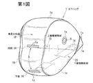
第1図は本発明の実施の形態に係るエアバッグの膨張状態における斜視図、第2図(a)はこのエアバッグの膨張状態における側面図、第2図(b)は第2図(a)のB−B線矢視図、第3図は第2図(b)のIII−III線に沿う断面図、第4図(a)は上部規制部材の平面図、第4図(b)は上部規制部材の分解平面図、第5図(a)は下部規制部材の平面図、第5図(b)は下部規制部材の分解斜視図、第6図は規制部材の開口付近の平面図、第7図は規制部材破断時における第6図と同様部分の平面図、第8図はエアバッグ内における規制部材の配置を示す平面図、第9〜17図はエアバッグの折り畳み手順の説明図、第18図はエアバッグ折り畳み体の断面図、第19,20図はエアバッグ膨張途中状態における車室内の助手席付近の側面図、第21図は膨張したエアバッグに小柄な乗員が対面した状態を示す第19,20図と同様部分の側面図、第22図は膨張したエアバッグに大柄な乗員が対面した状態を示す第19〜21図と同様部分の側面図、第23図は膨張したエアバッグが大柄な乗員を受け止めた状態を示す側面図である。 FIG. 1 is a perspective view of an airbag according to an embodiment of the present invention in an inflated state, FIG. 2 (a) is a side view of the airbag in an inflated state, and FIG. 2 (b) is FIG. ) Of FIG. 3B is a sectional view taken along line III-III of FIG. 2B, FIG. 4A is a plan view of the upper regulating member, and FIG. 4B. Is an exploded plan view of the upper regulating member, FIG. 5 (a) is a plan view of the lower regulating member, FIG. 5 (b) is an exploded perspective view of the lower regulating member, and FIG. 6 is a plan view of the vicinity of the opening of the regulating member. FIG. 7 is a plan view of the same portion as FIG. 6 when the regulating member is broken, FIG. 8 is a plan view showing the arrangement of the regulating member in the airbag, and FIGS. 9 to 17 are explanations of the airbag folding procedure. Fig. 18, Fig. 18 is a cross-sectional view of the airbag folding body, and Figs. 19 and 20 are sides near the passenger seat in the passenger compartment when the airbag is inflated. FIG. 21, FIG. 21 is a side view of the same part as FIG. 19 and 20 showing a state where a small occupant faces an inflated airbag, and FIG. 22 shows a state where a large occupant faces an inflated airbag. 19 is a side view of the same part as in FIGS. 19 to 21, and FIG. 23 is a side view showing a state in which the inflated airbag receives a large passenger.
なお、第9〜12図において、(a)図はエアバッグの正面図であり、(b)図は(a)図のB−B線に沿う断面図である。第13〜18図は、エアバッグの上下方向の断面図である。 9 to 12, (a) is a front view of the airbag, and (b) is a sectional view taken along line BB in (a). 13 to 18 are sectional views of the airbag in the vertical direction.
以下の説明において、前後方向及び左右方向は乗員にとっての前後方向及び左右方向をいう。 In the following description, the front-rear direction and the left-right direction refer to the front-rear direction and the left-right direction for the occupant.
この実施の形態におけるエアバッグ1は、車両の助手席用エアバッグである。
The
第19〜23図に示すように、この実施の形態における助手席用エアバッグ装置Sは、このエアバッグ1と、ケース2と、インフレータ3等を有している。このエアバッグ1は、折り畳まれてケース2内に収容され、インフレータ3によって膨張される。このケース2は、上面が開放した容器であり、その上面は自動車のインストルメントパネル4によって覆われている。インストルメントパネル4の上方にはウィンドシールド5が存在する。
As shown in FIGS. 19 to 23, the passenger seat airbag apparatus S in this embodiment includes the
このエアバッグ1は、第2図に示す通り、インフレータ3からガスが供給されることによりインストルメントパネル4の上面から該インストルメントパネル4とウィンドシールド5との間及び助手席前方の空間を埋めるように膨張する。この膨張したエアバッグ1の車体後方側の面が助手席乗員に対面する乗員対向面1Fとなる。
As shown in FIG. 2, the
第2図(a)に示すように、この実施の形態では、エアバッグ1が膨張した状態において、乗員対向面1Fのうち小柄な乗員の頭部付近と対面する領域がその周囲よりも反乗員側へ凹んだ凹部1Hとなるように構成されている。
As shown in FIG. 2 (a), in this embodiment, in the state in which the
この実施の形態では、エアバッグ1は、その膨張時の乗員対向面1F並びに上面及び下面を一続きに構成するセンターパネル1aと、左右の側面をそれぞれ構成する1対のサイドパネル1b,1cとを縫合してなる。
In this embodiment, the
第2図(a)に示すように、各サイドパネル1b,1cは、車体後方側ほど上下方向の幅が大きくなる略三角形状となっている。各サイドパネル1b,1cには、それぞれベントホール6が設けられている。このサイドパネル1b,1cの後辺に沿ってセンターパネル1aによりエアバッグ1の乗員対向面1Fが形成され、サイドパネル1b,1cの上側の斜辺に沿ってセンターパネル1aによりエアバッグ1の上面が形成され、サイドパネル1b,1cの下側の斜辺に沿ってセンターパネル1aによりエアバッグ1の下面が形成される。センターパネル1aは、両端がサイドパネル1b,1cの車体前方側の角部付近に配置され、相互に縫合等により結合されている。符号1sは、パネル(基布)同士を縫合したシームを示している。
As shown in FIG. 2 (a), each of the
各サイドパネル1b,1cの後辺のうちエアバッグ膨張時に小柄な乗員の頭部と対面する高さ付近は、部分的に車体前方側へ凹んでいる。エアバッグ膨張時には、このサイドパネル1b,1cの後辺の凹みに沿って乗員対向面1Fに前記凹部1Hが形成される。
Of the rear sides of the
なお、エアバッグ1のパネル構成及び凹部1Hの形成方法はこれに限定されない。
In addition, the panel structure of the
エアバッグ膨張時には、エアバッグ1の上面は、ウィンドシールド5の傾斜に沿って上端側ほど車体後方側となるように延在する。
When the airbag is inflated, the upper surface of the
エアバッグ1の膨張時における下面の車体前方側の端部(前端)付近に、インフレータ挿入用の1対のスリット1d,1d(第8図)が設けられている。該スリット1d,1dは、左右に間隔をあけて互いに略平行に延設されている。
A pair of
エアバッグ1の内部側から該エアバッグ1の下面の前端部付近に、該エアバッグ1をケース2に固定するための固定プレート7(第9〜18図)が重ね合わされている。
A fixing plate 7 (FIGS. 9 to 18) for fixing the
この固定プレート7は、略方形の平面視形状を有している。この固定プレート7の中央付近には、エアバッグ1の外部側へ膨出した略半円筒形状の膨出部7aが形成されている。この膨出部7aは、その軸心方向を略左右方向として形成されている。エアバッグ1の下面のスリット1d,1d同士の間の部分は、この膨出部7aの内周面に重なっており、該膨出部7aの左端及び右端がそれぞれ左右のスリット1d,1dに臨んでいる。また、固定プレート7のうち該膨出部7aよりも左端側及び右端側は、それぞれ、該膨出部7aと略同軸状にエアバッグ1の内部側へ張り出したC字形バンド部7bとなっている。各スリット1dの該膨出部7aと反対側の縁部は、それぞれ、各C字形バンド部7bの内周面に重なっている。
The fixed
この実施の形態では、前記インフレータ3は略円筒形のものであり、各スリット1d,1dを介してエアバッグ1内に挿入されている。このインフレータ3は、固定プレート7の膨出部7aに嵌め込まれ、両端が各C字形バンド部7bによって押え付けられることにより該固定プレート7に保持されている。
In this embodiment, the inflator 3 has a substantially cylindrical shape, and is inserted into the
固定プレート7の周縁部からは、エアバッグ1の外方へ向ってスタッドボルト7cが突設されている。このスタッドボルト7cは、エアバッグ1の下面に設けられたボルト挿通孔(図示略)を介してエアバッグ1の外部に延出している。このスタッドボルト7cによりエアバッグ1の下面の前端側がケース2の底面に連結されている。
A
エアバッグ1の前端側において、センターパネル1a及び各サイドパネル1b,1cの外面には、このエアバッグ1の前端側を包み込むように補強布1eが取り付けられている。また、各ベントホール6の周縁部には、各ベントホール6を取り囲む環形の補強布6aが取り付けられている。
On the front end side of the
エアバッグ1内には、前記スリット1d,1d付近のエアバッグ内面及びパネル1a,1b,1c同士の縫合部等を覆う防炎布1fが設けられている。
In the
このエアバッグ1内には、乗員対向面1Fのうちエアバッグ膨張時に小柄な乗員の頭部と対面する凹部1H付近とエアバッグ1の前端付近とを連結した規制部材10が設けられている。また、この実施の形態では、さらに、該乗員対向面1Fの下部(エアバッグ1の膨張時に凹部1Hよりも下方に位置する部分)1K付近とエアバッグ1の前端付近とを連結した副規制部材20が設けられている。
In the
この実施の形態では、規制部材10及び副規制部材20は、それぞれ太幅帯状のものとなっており、各々の幅方向が略左右方向となるように配設されている。これらの規制部材10及び副規制部材20のパネル構成については、後で詳しく述べる。
In this embodiment, the restricting
符号1xは、規制部材10の一端側を凹部1H付近に縫着したシームを示し、符号1yは、副規制部材20の一端側を乗員対向面1Fの下部1K付近に縫着したシームを示し、符号1z(第3,8図)は、これらの規制部材10及び副規制部材20の他端側をそれぞれエアバッグ1の前端付近に縫着したシームを示している。なお、これらの規制部材10及び副規制部材20のエアバッグ1への接続方法は縫着に限定されない。
以下、規制部材10を上部規制部材といい、副規制部材20を下部規制部材といい、これらを総称して規制部材10,20ということがある。
Hereinafter, the regulating
エアバッグ1が膨張した状態において、上部規制部材10と乗員対向面1Fの凹部1Hとの接続部(シーム1x)から下部規制部材20と乗員対向面1Fの下部1Kとの接続部(シーム1y)までのセンターパネル1aの外面に沿う間隔D(第1図)は400〜440mm、特に410〜430mm程度であることが好ましい。
In a state where the
上部規制部材10の長さは、エアバッグ1が第22図の如く規制部材10,20によって拘束されていない最大膨張形状まで膨張したときの前記凹部1H(シーム1x)から該エアバッグ1の前端部(シーム1z)までの直線距離の60〜80%、特に65〜75%程度であることが好ましい。また、下部規制部材20の長さは、このエアバッグ1が最大膨張形状まで膨張したときの乗員対向面1Fの下部1K(シーム1y)から該エアバッグ1の前端部(シーム1z)までの直線距離の40〜60%、特に45〜55%程度であることが好ましい。
The length of the upper restricting
第4図(a)及び第5図(a)に示すように、各規制部材10,20の長手方向の途中部には、それぞれ、該規制部材10,20を厚み方向に貫通する開口11,21が設けられている。これらの開口11,21は、それぞれ、各規制部材10,20の幅方向の中間付近に配置されている。各規制部材10,20のうち、これらの開口11,21と該規制部材10,20の左右の側辺との間の部分は、それぞれ、該規制部材10,20の他の部分よりも幅が狭く、これにより該規制部材10,20の他の部分よりも破断強度が低い脆弱部10a,20aとなっている。
As shown in FIG. 4 (a) and FIG. 5 (a), in the middle part in the longitudinal direction of each regulating
開口11即ち脆弱部10aは、上部規制部材10がエアバッグ1内でピンと張った状態において、該上部規制部材10の前端(シーム1z)から210〜240mm、特に220〜230mm程度離隔していることが好ましい。
The
開口21即ち脆弱部20aは、下部規制部材20がエアバッグ1内でピンと張った状態において、該下部規制部材20の前端(シーム1z)から190〜220mm、特に200〜215mm程度離隔していることが好ましい。
The
第4図(a)及び第5図(a)の通り、上部規制部材10の各脆弱部10aの幅W1は、下部規制部材20の各脆弱部20aの幅W2よりも大きなものとなっている。これにより、上部規制部材10の各脆弱部10aは、該規制部材10に負荷される張力T(第6図)に対する破断強度が下部規制部材20の各脆弱部20aに比べて高いものとなっている。
The street 4 Figure (a) and FIG. 5 (a), the width W 1 of the
この脆弱部10aの幅W1は25〜30mm、特に27〜29mm程度であることが好ましく、脆弱部20aの幅W2は17〜23mm、特に19〜21mm程度であることが好ましい。
Preferably the
下部規制部材20は、エアバッグ1の膨張時において、エアバッグ1が膨張開始してから好ましくは5〜35m秒後、特に好ましくは10〜30m秒後に、該規制部材20に負荷される張力により脆弱部20aが破断して、乗員対向面1Fの下部1Kとエアバッグ1の前端部との連結を解除するように構成されている。
When the
また、上部規制部材10は、エアバッグ1の膨張時において、該下部規制部材20の破断後であって、且つエアバッグ1が膨張開始してから好ましくは15〜40m秒後、特に好ましくは30〜40m秒後に、該規制部材10に負荷される張力により脆弱部10aが破断して、乗員対向面1Fの凹部1Hとエアバッグ1の前端部との連結を解除するように構成されている。
Further, the upper regulating
以下に、この規制部材10,20の構成についてさらに詳細に説明する。
Below, the structure of this
この実施の形態では、規制部材10は、エアバッグ1内において、一端がシーム1xにより乗員対向面1Fの凹部1H付近に接続された第1ハーフパネル12と、一端がシーム1zによりエアバッグ1の下面の前端付近に接続された第2ハーフパネル13とを備え、これらの第1ハーフパネル12と第2ハーフパネル13との他端同士がシーム14によって結合されたものとなっている。
In this embodiment, the regulating
また、規制部材20も、エアバッグ1内において、一端がシーム1yにより乗員対向面1Fの下部1K付近に接続された第1ハーフパネル22と、一端がシーム1zによりエアバッグ1の下面の前端付近に接続された第2ハーフパネル23とを備え、これらの第1ハーフパネル22と第2ハーフパネル23との他端同士がシーム24によって結合されたものとなっている。
The regulating
前記開口11,21は、それぞれ、該第1ハーフパネル12,22の該一端付近に設けられている。
The
各ハーフパネル12,13,22,23は、それぞれ、縦糸及び横糸により織製された織布よりなる。
Each
この実施の形態では、該第1ハーフパネル12,22は、それぞれ、該織布の糸目方向(縦糸及び横糸の延在方向)が各規制部材10,20の長手方向即ち張力方向に対し斜交方向となるように、該織布から切り出されたものである。
In this embodiment, the
本発明においては、第6図の通り、この第1ハーフパネル12,22の織布の糸目方向と各規制部材10,20の張力方向Tとの角度、即ちこの織布の縦糸の延在方向E1と規制部材20の張力方向Tとの角度θ1、及び織布の横糸の延在方向E2と規制部材20の張力方向Tとの角度θ2は、それぞれ、30〜60°、特に40〜50°であることが好ましい。
In the present invention, as shown in FIG. 6, the angle between the yarn direction of the woven fabric of the
各規制部材10,20の長手方向における開口11の幅W3(第4図(a))及び開口21の幅W4(第5図(a))は、それぞれ、各脆弱部10a,20aにおいて、織布の縦糸及び横糸がいずれも該脆弱部10a,20aの一端側から他端側まで連続せず、該脆弱部10a,20aの長手方向の途中で各規制部材10,20の左右の側辺又は開口11,21側の側辺に沿ってカットされて途切れたものとなるように設定されている。
The width W 3 (FIG. 4 (a)) of the
この開口11の幅W3は25〜30mm、特に27〜29mm程度であることが好ましく、開口21の幅W4は17〜23mm、特に19〜21mm程度であることが好ましい。 The width W 3 of the opening 11 is preferably about 25 to 30 mm, particularly about 27 to 29 mm, and the width W 4 of the opening 21 is preferably about 17 to 23 mm, particularly about 19 to 21 mm.
第2ハーフパネル13,23は、この実施の形態では、それぞれ、織布の糸目方向が各規制部材10,20の長手方向即ち張力方向と略平行方向及び略直交方向となるように、該織布から切り出されている。これにより、該第2ハーフパネル13,23は、第1ハーフパネル12,22に比べて張力Tに対する破断強度が高いものとなっている。
In this embodiment, the
この実施の形態では、上部規制部材10の長手方向と直交方向の幅W5(第4図(a))は、後述のように、エアバッグ1の折り畳み体の左右方向の幅W6(第12図(a))と略同等となっている。なお、この実施の形態では、エアバッグ1は、前記固定プレート7の左右幅と略同等の左右幅となるように折り畳まれる。本発明においては、この上部規制部材10の幅W5は、100〜200mm、特に140〜160mm程度であることが好ましい。
In this embodiment, the width W 5 (FIG. 4 (a)) in the direction orthogonal to the longitudinal direction of the upper regulating
この実施の形態では、下部規制部材20も上部規制部材10と略同等の幅とされている。
In this embodiment, the lower restricting
この実施の形態では、上部規制部材10の第1ハーフパネル12の前記一端側から該規制部材10の延長方向に延長部15が延出している。この延長部15が第1ハーフパネル12の前記他端側へ折り返されてシーム16により縫着されることにより、第1ハーフパネル12の該一端側が高強度となり、第1ハーフパネル12が乗員対向面1Fに対しシーム1xにより強固に結合されている。
In this embodiment, the
上部規制部材10の第1ハーフパネル12の長さ(シーム1x,14間の長さ)L1は270〜310mm、特に280〜300mm程度であることが好ましく、第2ハーフパネル13の長さ(シーム14,1z間の長さ)L2は20〜60mm、特に30〜50mm程度であることが好ましい。また、下部規制部材20の第1ハーフパネル22の長さ(シーム1y,24間の長さ)L3は210〜250mm、特に220〜240mm程度であることが好ましく、第2ハーフパネル23の長さ(シーム24,1z間の長さ)L4は50〜90mm、特に60〜80mm程度であることが好ましい。
The length L 1 of the
この実施の形態では、第3図に示すように、下部規制部材20の第2ハーフパネル23の前端側がエアバッグ1の下面の前端付近に重ね合わされ、その上に上部規制部材10の第2ハーフパネル13の前端側が重ね合わされ、さらにその上に前記防炎布1fが重ね合わされた後、これらが一体的にシーム1zにより該エアバッグ1の下面に縫着されている。詳しい図示は省略するが、これらの第2ハーフパネル13,23及び防炎布1fにも、それぞれ、エアバッグ1の下面の前記スリット1d,1d及びボルト挿通孔と重なるスリット及びボルト挿通孔が設けられている。
In this embodiment, as shown in FIG. 3, the front end side of the
前記固定プレート7は、この防炎布1fの上からエアバッグ1の下面に重ね合わされている。上部規制部材10は、この固定プレート7の後縁側から車体後方へ延出している。即ち、この実施の形態では、該上部規制部材10の前端側は、インフレータ3よりも車体後方側においてエアバッグ1の下面に連なったものとなっている。
The fixing
第8図に示すように、この実施の形態では、該防炎布1fは、その後縁側が上部規制部材10のハーフパネル12,13同士の結合部(シーム14)をも覆う大きさとなっている。
As shown in FIG. 8, in this embodiment, the
この実施の形態では、少なくとも上部規制部材10の第1ハーフパネル12及び第2ハーフパネル13のエアバッグ膨張時における上面側に、耐熱樹脂コーティングが施されている。なお、この耐熱樹脂コーティングは、該第1ハーフパネル12及び第2ハーフパネル13の下面側にも施されてもよい。あるいは、該第1ハーフパネル12及び第2ハーフパネル13のうち必要な箇所に部分的に耐熱樹脂コーティングが施されていてもよい。下部規制部材20の第1ハーフパネル22及び第2ハーフパネル23にも耐熱樹脂コーティングが施されていてもよい。
In this embodiment, at least the upper surface side of the upper regulating
このように構成されたエアバッグ1は、折り畳まれて保形クロス30によって保形されて前記ケース2内に収容されている。この保形クロス30には、ミシン目状の破断予定部31が設けられており、保形クロス30は、エアバッグ膨張時にはこの破断予定部31において破断してエアバッグ折り畳み体の保形を解除するように構成されている。
The
この実施の形態では、該保形クロス30は帯状のものであり、その一端側(基端側)がエアバッグ1の前端部に連結されている。この保形クロス30の他端側(先端側)には、前記スタッドボルト7cが挿通されるボルト挿通孔32が設けられている。
In this embodiment, the shape-retaining
以下に、このエアバッグ1の折り畳み方法について説明する。
Below, the folding method of this
まず、第9図(a),(b)のように、乗員対向面1Fを上下左右に引き伸ばしつつ該乗員対向面1Fをエアバッグ1の前端側に接近させるようにして、エアバッグ1を平たく展延させる。符号1g,1h,1i,1jは、それぞれ、このように平たく展延したエアバッグ1の上端、下端、左端及び右端を示している。
First, as shown in FIGS. 9 (a) and 9 (b), the
この際、エアバッグ1内において、上部規制部材10の後端側(乗員対向面1F側)付近をエアバッグ1の上端1g側へ引っ張り、この上部規制部材10がその前端側(エアバッグ1の前端側)から該後端側付近まで乗員対向面1Fに沿ってピンと張るようにする。
At this time, in the
次に、第10図(a),(b)のように、このエアバッグ1の左右方向の中央付近から右半側を左半側の乗員対向面1Fの上に折り返す。次いで、第11図(a),(b)のように、このエアバッグ1の該右半側を右端1jから所定幅ずつ右方へ折り返してロール折りする。さらに、第12図(a),(b)のように、エアバッグ1の左半側も、左端1iから所定幅ずつエアバッグ中央側へ折り返してロール折りする。この際、エアバッグ1の該右半側及び左半側のロール折り体の左右幅の合計W6が固定プレート7の左右幅と略同等となるようにする。
Next, as shown in FIGS. 10 (a) and 10 (b), the right half side is folded back on the left half
なお、先にエアバッグ1の左半側を折り畳んでから右半側を折り畳んでもよい。
The left half side of the
第12図(b)のように、この実施の形態では、上部規制部材10の幅は、このエアバッグ1の折り畳み体の左右幅W6と略同等となっている。そのため、上部規制部材10は、このエアバッグ1の折り畳み体の内部において、該エアバッグ1内を上部規制部材10よりも上端1g側と下端1h側とに仕切るように延在した状態となる。以下、エアバッグ1内のうちこの上部規制部材10よりも上端1g側を上部室1Uと称し、下端1h側を下部室1Lと称する。
As Fig. 12 (b), in this embodiment, the width of the
前述の通り、この実施の形態では、上部規制部材10の前端側はインフレータ3よりも車体後方側においてエアバッグ1の下面に連なっているので、該インフレータ3は、第9図(b)の如く、この上部室1Uに臨んだものとなる。
As described above, in this embodiment, the front end side of the upper regulating
次に、第13図のように、エアバッグ1の下端1hからエアバッグ1の上下方向の中央よりも該下端1h側の所定位置まで、乗員対向面1Fと反対側へジグザグ状に折り畳む。次いで、第14図のように、このジグザグ折り部分を含むエアバッグ1の下半側を、該エアバッグ1の中央付近から上半側の乗員対向面1Fの上に折り返す。その後、第15図の通り、このエアバッグ1の下半側の残りの部分でジグザグ折り部分を包むように、エアバッグ1の下半側をエアバッグ1の中央側へロール折りする。
Next, as shown in FIG. 13, the
次に、第16図のように、エアバッグ1の上端1gからエアバッグ1の上下方向の中央よりも該上端1g側の所定位置まで、乗員対向面1Fと反対側へジグザグ状に折り畳む。次いで、第17図のように、このジグザグ折り部分を、エアバッグ1の上半側の残りの部分で包みつつ、該エアバッグ1の下半側の折り畳み体の上に載置する。
Next, as shown in FIG. 16, the
その後、第18図のように、保形クロス30をこのエアバッグ1の折り畳み体に巻回し、その先端側のボルト挿通孔32にスタッドボルト7cを挿通して該保形クロス30を掛止する。
Thereafter, as shown in FIG. 18, the shape-retaining
これにより、エアバッグ1の折り畳みが完了する。
Thereby, folding of the
なお、上記の折り畳み方法は一例にすぎず、本発明においては、上記以外の折り畳み方法にてエアバッグ1が折り畳まれてもよい。
In addition, said folding method is only an example and in this invention, the
次に、このように構成されたエアバッグ1を備えた助手席用エアバッグ装置Sの作動について説明する。
Next, the operation of the passenger airbag device S including the
この助手席用エアバッグ装置Sを搭載した車両の衝突時には、インフレータ3がガス噴出作動し、このインフレータ3からのガスによりエアバッグ1が膨張を開始する。このエアバッグ1は、前記リッドを押し開けて、インストルメントパネル4の上面から車室内に膨らみ出す。
At the time of a collision of a vehicle equipped with the passenger seat airbag device S, the inflator 3 performs gas ejection operation, and the
この際、前述の通り、エアバッグ1の折り畳み体の内部は、上部規制部材10により、該上部規制部材10よりも上側の上部室1Uと、下側の下部室1Lとに仕切られており、且つインフレータ3は該上部室1Uに臨んでいるので、このインフレータ3からのガスは、主として該上部室1Uに流入する。そのため、エアバッグ1は、該上部室1Uが迅速に膨張する。このとき、上部規制部材10の開口11は、該上部規制部材10の前端側から離隔しているので、インフレータ3からの噴出ガスが上部規制部材10に案内されて乗員側へ流れ易く、上部室1Uが速やかに乗員側へ膨張する。
At this time, as described above, the inside of the folded body of the
また、この際、エアバッグ1は、まず下半側が折り畳まれ、次いで上半側が折り畳まれて該下半側の折り畳み体の上に載置された状態となっているので、該上半側が下半側に先行して車室内に展開する。これにより、第19図の通り、エアバッグ1は、その上半側が速やかにインストルメントパネル4とウィンドシールド5との間、及び乗員頭部前方の空間を埋めるように膨張展開する。
At this time, since the
乗員対向面1Fは、該上部規制部材10がピンと張った状態となるまで乗員側へ膨出する。
The
インフレータ3から該上部室1Uに流入したガスは、上部規制部材10の開口11及び該上部規制部材10とエアバッグ1の左右の側面との間を通って下部室1Lに流入する。これにより、第19図〜第20図の通り、エアバッグ1の下半側が乗員胴体部前方の空間を埋めるように膨張展開する。乗員対向面1Fの下部1K側は、該下部規制部材20がピンと張った状態となるまで乗員側へ膨出する。
The gas flowing into the upper chamber 1U from the inflator 3 flows into the
この際、エアバッグ1が膨張開始してから好ましくは5〜35m秒、特に好ましくは10〜30m秒経過するまでは、下部規制部材20は乗員対向面1Fの下部1Kとエアバッグ1の前端側とを連結している。これにより、エアバッグ1の膨張初期の段階においてエアバッグ1の下半側がバタつくことが防止ないし抑制される。また、この下部規制部材20によりエアバッグ1の下半側の容積が減じられているので、エアバッグ1内が速やかに昇圧する。
At this time, the lower regulating
エアバッグ1が膨張開始してから好ましくは5〜35m秒後、特に好ましくは10〜30m秒後に、下部規制部材20が破断する。これにより、第21図の通り、エアバッグ1の下半側がさらに乗員側へ膨張して乗員の下半身を拘束するようになる。
Preferably, the lower regulating
この下部規制部材20の破断後であって、エアバッグ1が膨張開始してから好ましくは15〜40m秒後、特に好ましくは30〜40m秒後には、上部規制部材10が破断する。
After the lower restricting
乗員が小柄であり、座席を前方へスライドさせて着座している場合には、エアバッグ1が膨張開始してから上部規制部材10が破断する前に、乗員頭部がエアバッグ1に接触することがある。この場合、まだ上部規制部材10は破断していないので、第21図の通り、乗員対向面1Fのうち小柄な乗員の頭部と対面する凹部1H付近は、該上部規制部材10により反乗員側へ引っ張られた状態となっている。そのため、この小柄な乗員の頭部に凹部1H付近が強く接触することが防止され、この小柄な乗員の頭部が比較的ソフトに受け止められる。
When the occupant is small and is seated by sliding the seat forward, the occupant head contacts the
乗員が座席を前方へスライドさせることなく着座している場合には、通常、上部規制部材10が破断した後に、乗員頭部がエアバッグ1に接触する。この場合、乗員頭部がエアバッグ1に接触する前に、上部規制部材10が破断し、これにより、エアバッグ1の上部側がさらに乗員側へ膨出し、エアバッグ1は、第23図の通り、最大膨張形状まで膨張展開するようになる。この結果、乗員の頭部は、過度に前方移動する前にエアバッグ1によって受け止められるようになる。また、膨張したエアバッグ1の上部側の車体前後方向の厚みも十分に大きなものとなり、第25図のように、十分に乗員頭部の前方移動を拘束することができる。
When the occupant is seated without sliding the seat forward, the occupant head normally contacts the
なお、乗員が正規の着座位置よりも前方に位置した所謂アウトオブポジションの状態にあるときには、エアバッグ1が膨張開始した後、早期のうちにエアバッグ1に乗員が接触することがある。このエアバッグ1にあっては、その膨張初期の段階においては、各規制部材10,20により容積が減じられており、エアバッグ1内が速やかに昇圧するため、このアウトオブポジションの乗員もしっかりと受け止めることができる。
Note that when the occupant is in a so-called out-of-position state where the occupant is positioned in front of the normal seating position, the occupant may come into contact with the
この実施の形態では、各規制部材10,20の脆弱部10a,20aにおいては、織布の縦糸及び横糸の糸目方向が該規制部材10,20の張力方向Tに対し斜交方向となっており、これらの縦糸及び横糸は、いずれも、該脆弱部10a,20aの一端側から他端側まで連続せず、該脆弱部10a,20aの長手方向の途中で途切れたものとなっている。そのため、各規制部材10,20に所定以上の張力が負荷されると、各脆弱部10a,20aを構成する織布の縦糸及び横糸がそれぞれ織り組織から引き抜かれるようにしてこの織布の織りがほぐれ、これにより各脆弱部10a,20aが破断する。
In this embodiment, in the
なお、脆弱部10a,20aを構成する織布の糸目方向が規制部材10,20の張力方向Tと略同一方向となっている場合には、脆弱部10a,20aの破断前には、この織布の縦糸及び横糸の一方が該脆弱部10a,20aの一端側から他端側まで連続した状態となっている。そのため、脆弱部10a,20aが破断する際には、この脆弱部10a,20aの一端から他端まで連続した糸が切れる必要がある。しかしながら、このように糸が切れることにより脆弱部10a,20aが破断するように構成されている場合には、この糸の破断強度は温度依存性が大きいため、インフレータ3からの噴出ガスの熱の影響を受け易く、インフレータ3の形状や配置等によってこの糸が切れるタイミング、即ち脆弱部10a,20aの破断のタイミングにバラつきが生じ易い。
When the yarn direction of the woven fabric constituting the
これに対し、この実施の形態のエアバッグ1にあっては、脆弱部10a,20aの破断時には、織布の縦糸及び横糸が切れることなく、該縦糸及び横糸が織り組織から引き抜かれるようにして織布の織りがほぐれることにより脆弱部10a,20aが破断するので、この脆弱部10a,20aの破断に際しインフレータ3からの噴出ガスの熱の影響を受けにくい。従って、このエアバッグ1にあっては、インフレータ3の形状や配置によって脆弱部10a,20aの破断のタイミングにバラつきが生じにくい。また、このエアバッグ1を備えたエアバッグ装置Sにあっては、インフレータ3の選択の自由度や、インフレータ3の配置の自由度が高い。
On the other hand, in the
この実施の形態では、脆弱部10a,20aを構成するための開口11,21が各規制部材10,20の前端側から十分に離隔しているので、これらの脆弱部10a,20aは、さらにインフレータ3からの噴出ガスの熱の影響を受けにくいものとなっている。
In this embodiment, since the
この実施の形態では、各規制部材10,20のうちエアバッグ1の前端側の部分を構成する第2ハーフパネル13,23は、それぞれ織布の糸目方向が各規制部材10,20の張力方向Tと略平行方向及び略直交方向となっており、破断強度が高いので、各規制部材10,20が強固にエアバッグ1の前端側に接続されている。
In this embodiment, the
この実施の形態では、上部規制部材10の第1ハーフパネル12と第2ハーフパネル13とを連結したシーム14が防炎布1fによって覆われているので、インフレータ3からの熱によりこのシーム14が破断することが防止される。
In this embodiment, since the
上記の第1〜23図の実施の形態では、上部規制部材10の前端側は、インフレータ3よりも車体後方側においてエアバッグ1の下面に連なっているが、本発明においては、上部規制部材10の前端側は、インフレータ3よりも車体前方側においてエアバッグ1の下面に連なっていてもよい。第24図は、このように構成されたエアバッグの縦断面図である。
In the embodiment shown in FIGS. 1 to 23 described above, the front end side of the upper regulating
この実施の形態では、上部規制部材10をエアバッグ1の前端側に接続するに当り、該上部規制部材10の前端側を所定長さにわたって該上部規制部材10の下面側に折り返し、その折り目を車体前方側に向けた姿勢で、この折り返した部分をエアバッグ1の前端側の下面にシーム1zにより縫着している。この上部規制部材10の前端側の縫着部の上に防炎布1fを介して固定プレート7が重ね合わされ、該固定プレート7にインフレータ3が保持されている。上部規制部材10は、該固定プレート7の前縁側を回り込み、インフレータ3の上方を通って車体後方側へ延在している。これにより、上部規制部材10は、前端側がインフレータ3よりも車体前方側においてエアバッグ1の下面に連なったものとなり、インフレータ3は、この上部規制部材10よりも下側の下部室1L内に配置されたものとなっている。
In this embodiment, when the upper regulating
この実施の形態のその他の構成は前述の第1〜23図の実施の形態と同様であり、第24図において第1〜23図と同一符号は同一部分を示している。 The other structure of this embodiment is the same as that of the above-described embodiment shown in FIGS. 1 to 23. In FIG. 24, the same reference numerals as those in FIGS. 1 to 23 denote the same parts.
この実施の形態では、インフレータ3がエアバッグの下部室1L内に配置されているので、インフレータ3がガス噴出作動すると、該インフレータ3からのガスは、まず下部室1L内に流入する。そのため、エアバッグ膨張時には、該エアバッグ1の下部側が迅速に膨張展開する。
In this embodiment, since the inflator 3 is disposed in the
上記の各実施の形態はいずれも本発明の一例を示すものであり、本発明は上記の各実施の形態に限定されない。 Each of the above embodiments shows an example of the present invention, and the present invention is not limited to each of the above embodiments.
例えば、上記の実施の形態では、乗員対向面1Fのうちエアバッグ1の膨張時に小柄な乗員の頭部付近と対面する凹部1Hをエアバッグ1の前端側に連結した上部規制部材10の他に、該乗員対向面1Fの下部1Kをエアバッグ1の前端側に連結した下部規制部材20が設けられているが、エアバッグ1に設けられる規制部材としての規制部材の本数や配置はこれに限定されない。
For example, in the above embodiment, in addition to the upper regulating
上記実施の形態では、上部規制部材10は、凹部1Hの最深部に接続されているが、上部規制部材10の乗員対向面1Fへの接続位置はこれに限定されるものではなく、この凹部1Hの最深部以外の箇所(例えば凹部1Hの最深部よりも上側)において乗員対向面1Fに接続されてもよい。また、凹部1Hの最深部は、エアバッグ1の膨張時に小柄な乗員の頭部と対面する位置から(例えば下方に)ずれていてもよい。
In the above embodiment, the upper restricting
上記の実施の形態では、各規制部材10,20は、乗員対向面1F側の第1ハーフパネル12,22と、エアバッグ1の前端側の第2ハーフパネル13,23とを連結した構成となっているが、各規制部材10,20の構成はこれに限定されない。例えば、各規制部材10,20は、それぞれ一端側から他端側まで連続した1枚の織布により構成されてもよい。また、3枚以上のハーフパネルを連結した構成であってもよい。
In the above embodiment, each regulating
1 エアバッグ
1F 乗員対向面
1H 凹部
10 規制部材
10a 脆弱部
11 開口
12 第1ハーフパネル
13 第2ハーフパネル
20 副規制部材
20a 脆弱部
21 開口
22 第1ハーフパネル
23 第2ハーフパネル
DESCRIPTION OF
Claims (14)
該エアバッグを形成すると共に、エアバッグ膨張時に乗員の頭部と対面する頭部対面部を有する乗員対向面を備えたパネルと、
エアバッグ膨張時に該頭部対面部に形成される凹部と、
該頭部対面部の乗員側への膨出を規制するための規制部材であって、エアバッグ膨張時に該頭部対面部の乗員側への膨出を規制することにより該凹部を形成する規制部材と、
エアバッグ膨張時に、該凹部よりも下方に位置する該乗員対向面の下部を連結するためのものであり、該規制部材よりも長さが短い副規制部材と
を備えており、
該規制部材及び副規制部材は帯状のものであり、
該規制部材は、エアバッグが膨張を開始してから所定時間経過後に規制を解除するように構成されており、
該副規制部材は、エアバッグ膨張時において、該規制部材が規制を解除する前に破断するように構成されており、
該規制部材は、エアバッグ膨張時において、該エアバッグ内を、該規制部材よりも該エアバッグの上端側の上部室と、該規制部材よりも該エアバッグの下端側の下部室とに仕切るように延在しており、
該エアバッグは、該上部室内にインフレータからのガスが供給されるように構成されており、
該エアバッグは、折り畳まれた状態でエアバッグ装置に設置されるものであり、
該エアバッグは、折り畳まれた状態にあっては、その膨張時の上半側の折り畳み体が下半側の折り畳み体の上に載置されるように折り畳まれており、
該エアバッグは、膨張時には、該乗員対向面のうち該頭部対面部よりも上側の部分が該下部よりも早期に乗員側へ膨張するものとなっており、
前記規制部材は、エアバッグ内部に配置され、該頭部対面部と、エアバッグの膨張時の反乗員側とを連結しており、
該規制部材は、エアバッグが膨張を開始してから前記所定時間経過後に該規制部材に負荷される張力(以下、規制部材張力という。)により破断して該頭部対面部と該反乗員側との連結を解除するように構成されており、
該規制部材に脆弱部(以下、規制部材脆弱部という。)が設けられており、該規制部材に該規制部材張力が負荷されたときには、該規制部材脆弱部において該規制部材が破断するように構成されており、
該規制部材に開口(以下、規制部材開口という。)が設けられており、該規制部材開口の周縁部が該規制部材脆弱部となっており、
該規制部材開口は、該規制部材をその厚み方向(以下、規制部材厚み方向という。)に貫通したものであり、
該規制部材の該規制部材張力方向及び該規制部材厚み方向の双方と直交する方向(以下、規制部材幅方向という。)の両端側の各側辺と該規制部材開口との間がそれぞれ該規制部材脆弱部となっており、
前記副規制部材に脆弱部(以下、副規制部材脆弱部という。)が設けられており、エアバッグが膨張を開始してから前記規制部材が規制を解除する前に、該副規制部材に負荷された張力(以下、副規制部材張力という。)により、該副規制部材脆弱部において該副規制部材が破断するように構成されており、
該副規制部材に開口(以下、副規制部材開口という。)が設けられており、該副規制部材開口の周縁部が該副規制部材脆弱部となっており、
該副規制部材開口は、該副規制部材をその厚み方向(以下、副規制部材厚み方向という。)に貫通したものであり、
該副規制部材の該副規制部材張力方向及び該副規制部材厚み方向の双方と直交する方向(以下、副規制部材幅方向という。)の両端側の各側辺と該副規制部材開口との間がそれぞれ該副規制部材脆弱部となっており、
該副規制部材幅方向における該副規制部材脆弱部の幅は、該規制部材幅方向における該規制部材脆弱部の幅よりも小さなものとなっており、
該副規制部材張力方向における該副規制部材開口の幅は、該規制部材張力方向における該規制部材開口の幅よりも小さなものとなっており、
これにより、エアバッグが膨張を開始してから該規制部材脆弱部が該規制部材張力により破断する前に、該副規制部材脆弱部が該副規制部材張力により破断するように構成されていることを特徴とするエアバッグ。 An airbag for restraining an occupant, the airbag being
A panel having an occupant-facing surface having a head-facing portion facing the occupant's head when the airbag is inflated, and forming the airbag;
A recess formed in the head-to-face portion when the airbag is inflated;
A restricting member for restricting the bulge of the head-facing portion toward the occupant side, wherein the concavity is formed by restricting the bulge of the head-facing portion toward the occupant when the airbag is inflated. A member,
When the airbag is inflated, it is for connecting a lower portion of the occupant-facing surface located below the recess, and includes a sub-regulating member having a length shorter than the regulating member,
The regulation member and the sub-regulation member are band-shaped,
The regulating member is configured to release the regulation after a predetermined time has elapsed since the airbag started to inflate,
The secondary regulating member is configured to be broken before the regulating member releases the regulation when the airbag is inflated.
The regulating member partitions the inside of the airbag into an upper chamber on the upper end side of the airbag with respect to the regulating member and a lower chamber on the lower end side of the airbag with respect to the regulating member when the airbag is inflated. And so on
The airbag is configured so that gas from an inflator is supplied into the upper chamber,
The airbag is installed in the airbag device in a folded state,
When the airbag is in a folded state, the airbag is folded so that the folded body on the upper half side is placed on the folded body on the lower half side,
When the airbag is inflated, the portion above the head-facing portion of the occupant-facing surface is inflated to the occupant side earlier than the lower portion .
The regulating member is disposed inside the airbag, and connects the head-facing portion and the side opposite to the occupant when the airbag is inflated,
The regulating member is broken by a tension (hereinafter referred to as regulating member tension) applied to the regulating member after the predetermined time has elapsed after the airbag starts to inflate, and the head-to-face portion and the opposite occupant side Is configured to release the connection with
The restricting member is provided with a fragile portion (hereinafter referred to as a restricting member fragile portion), and when the restricting member tension is applied to the restricting member, the restricting member is broken at the restricting member fragile portion. Configured,
The restricting member is provided with an opening (hereinafter referred to as restricting member opening), and a peripheral portion of the restricting member opening is the restricting member weak part,
The restricting member opening penetrates the restricting member in the thickness direction (hereinafter referred to as restricting member thickness direction).
Between each side of both ends of the direction perpendicular to both the regulating member tension direction and the regulating member thickness direction of the regulating member (hereinafter referred to as regulating member width direction) and the regulating member opening are respectively regulated. It is a fragile part,
The sub-regulating member is provided with a fragile portion (hereinafter referred to as a sub-regulating member fragile portion), and a load is applied to the sub-regulating member before the regulation member releases the regulation after the airbag starts to inflate. The sub-regulator member is configured to break at the weak portion of the sub-regulator member due to the applied tension (hereinafter referred to as sub-regulator member tension)
The sub-regulator member is provided with an opening (hereinafter referred to as sub-regulator member opening), and the peripheral portion of the sub-regulator member opening is the sub-regulator member weakened portion,
The sub-regulating member opening penetrates the sub-regulating member in its thickness direction (hereinafter referred to as a sub-regulating member thickness direction).
Between each side edge of both ends of the direction (hereinafter referred to as a sub-regulating member width direction) orthogonal to both the sub-regulating member tension direction and the sub-regulating member thickness direction of the sub-regulating member, and the sub-regulating member opening. Each space is the weak part of the sub-regulatory member,
The width of the sub-regulating member fragile portion in the sub-regulating member width direction is smaller than the width of the regulating member fragile portion in the regulating member width direction,
The width of the sub regulating member opening in the sub regulating member tension direction is smaller than the width of the regulating member opening in the regulating member tension direction,
Thereby, after the airbag starts to be inflated, before the restricting member fragile portion is broken by the restricting member tension, the sub restricting member fragile portion is broken by the sub restricting member tension. Air bag characterized by.
該折り返し部の折り目は車体前方側を向いていることを特徴とするエアバッグ。 In any 1 item | term of the Claims 1 thru | or 9 , The said control member is connected with the front-end part on the opposite side to the said passenger | crew opposing surface of the said airbag, And the front end side of this control member is carried out over predetermined length. Having a folded portion folded on the lower surface side of the front end when the airbag is folded,
The airbag according to claim 1, wherein the fold of the turn-up portion faces the front side of the vehicle body.
該第2ハーフパネルは、該第1ハーフパネルに比べて破断強度が高いものとなっていることを特徴とするエアバッグ。 In any one of claims 1 to 10, wherein the regulating member has one end and the first half panel connected to the recess of the occupant-facing surface, one end opposite the occupant-facing surface of the airbag A second half panel connected to the front end, and the other ends of the first half panel and the second half panel are combined,
The airbag, wherein the second half panel has a higher breaking strength than the first half panel.
該第2ハーフパネルは、該第1ハーフパネルに比べて破断強度が高いものとなっていることを特徴とするエアバッグ。 In any one of claims 1 to 11, wherein the sub-regulating member, opposite the first half panel, the occupant-facing surface of one end of the airbag, one end of which is connected to the lower portion of the occupant-facing surface A second half panel connected to the front end of the first half panel, and the other ends of the first half panel and the second half panel are joined together,
The airbag, wherein the second half panel has a higher breaking strength than the first half panel.
該エアバッグの該前端部における前記パネルの表面に取り付けられた補強布と
を備えていることを特徴とするエアバッグ。 The airbag according to any one of claims 1 to 12 , further comprising a front end portion on a side opposite to the occupant-facing surface;
An airbag comprising: a reinforcing cloth attached to a surface of the panel at the front end portion of the airbag.
Priority Applications (3)
| Application Number | Priority Date | Filing Date | Title |
|---|---|---|---|
| JP2008327977A JP5195400B2 (en) | 2008-12-24 | 2008-12-24 | Air bag and air bag device |
| US12/591,854 US8196957B2 (en) | 2008-12-24 | 2009-12-03 | Airbag and airbag device |
| CN2009102532651A CN101758811B (en) | 2008-12-24 | 2009-12-11 | Airbag and airbag device |
Applications Claiming Priority (1)
| Application Number | Priority Date | Filing Date | Title |
|---|---|---|---|
| JP2008327977A JP5195400B2 (en) | 2008-12-24 | 2008-12-24 | Air bag and air bag device |
Publications (3)
| Publication Number | Publication Date |
|---|---|
| JP2010149594A JP2010149594A (en) | 2010-07-08 |
| JP2010149594A5 JP2010149594A5 (en) | 2012-09-06 |
| JP5195400B2 true JP5195400B2 (en) | 2013-05-08 |
Family
ID=42264886
Family Applications (1)
| Application Number | Title | Priority Date | Filing Date |
|---|---|---|---|
| JP2008327977A Expired - Fee Related JP5195400B2 (en) | 2008-12-24 | 2008-12-24 | Air bag and air bag device |
Country Status (3)
| Country | Link |
|---|---|
| US (1) | US8196957B2 (en) |
| JP (1) | JP5195400B2 (en) |
| CN (1) | CN101758811B (en) |
Families Citing this family (22)
| Publication number | Priority date | Publication date | Assignee | Title |
|---|---|---|---|---|
| JP2010158914A (en) * | 2007-08-10 | 2010-07-22 | Autoliv Development Ab | Airbag device |
| DE102010039759A1 (en) * | 2010-06-30 | 2012-01-05 | Takata-Petri Ag | Airbag arrangements for a steering wheel of a motor vehicle |
| JP2012066613A (en) * | 2010-09-21 | 2012-04-05 | Toyota Motor Corp | Airbag device for front passenger seat |
| US8657334B2 (en) * | 2011-02-11 | 2014-02-25 | Key Safety Systems, Inc. | Airbag cushion |
| JP2012171412A (en) * | 2011-02-18 | 2012-09-10 | Toyoda Gosei Co Ltd | Temporary holding method for airbag, and airbag module |
| KR101884445B1 (en) * | 2011-10-10 | 2018-08-02 | 현대모비스 주식회사 | Passenger airbag cushion and method for folding passenger airbag cushion |
| JP5760929B2 (en) * | 2011-10-07 | 2015-08-12 | トヨタ自動車株式会社 | Airbag device |
| JP5747799B2 (en) * | 2011-11-30 | 2015-07-15 | トヨタ自動車株式会社 | Airbag device for passenger seat |
| US8807596B1 (en) * | 2013-01-31 | 2014-08-19 | Ford Global Technologies, Llc | Airbag and vehicle passenger restraint system |
| JP6676933B2 (en) * | 2015-11-11 | 2020-04-08 | Joyson Safety Systems Japan株式会社 | Airbag and airbag device |
| CN107235028B (en) * | 2016-03-29 | 2021-10-01 | 奥托立夫开发公司 | Airbag and airbag module |
| US10486635B2 (en) * | 2016-04-08 | 2019-11-26 | Joyson Safety Systems Acquisition Llc | Rear seat airbag module |
| US10427638B2 (en) * | 2016-06-08 | 2019-10-01 | Autoliv Asp, Inc. | Frontal airbag assemblies for reducing rotational velocity of a head of an occupant |
| WO2018167919A1 (en) * | 2017-03-16 | 2018-09-20 | 本田技研工業株式会社 | Occupant protection apparatus |
| JP6880954B2 (en) * | 2017-04-07 | 2021-06-02 | トヨタ自動車株式会社 | Vehicle side airbag device and its manufacturing method |
| DE102017124576A1 (en) * | 2017-10-20 | 2019-04-25 | Dalphi Metal Espana, S.A. | VEHICLE BASE RESTRAINT SYSTEM WITH A GAS CABLE MODULE AND METHOD FOR ASSEMBLING A GAS BAG |
| JP7070264B2 (en) * | 2018-09-12 | 2022-05-18 | トヨタ自動車株式会社 | Vehicle airbag device |
| CN109760617B (en) * | 2019-03-08 | 2024-04-26 | 延锋汽车智能安全系统有限责任公司 | Safety airbag for protecting head, neck, chest and legs of passenger |
| CN114174129B (en) * | 2019-08-22 | 2023-10-17 | 奥托立夫开发公司 | Protective cover for airbag and airbag device for vehicle |
| US11772595B2 (en) * | 2021-07-01 | 2023-10-03 | ZF Passive Safety Systems US Inc. | Airbag with reinforced tether |
| JPWO2023105902A1 (en) * | 2021-12-10 | 2023-06-15 | ||
| US12036941B1 (en) * | 2023-04-19 | 2024-07-16 | GM Global Technology Operations LLC | Airbag with extended horizontal cushion preventing head and knee contact |
Family Cites Families (17)
| Publication number | Priority date | Publication date | Assignee | Title |
|---|---|---|---|---|
| US4928905A (en) | 1989-05-01 | 1990-05-29 | Arena Recreations (Toronto) Limited | One-way clutch assembly |
| JP3003182B2 (en) | 1990-08-20 | 2000-01-24 | タカタ株式会社 | How to fold the passenger airbag |
| JP3168591B2 (en) * | 1991-03-12 | 2001-05-21 | トヨタ自動車株式会社 | Airbag device |
| US5308113A (en) * | 1992-10-09 | 1994-05-03 | Trw Vehicle Safety Systems Inc. | Airbag inflation-controlling member |
| GB2271322B (en) * | 1992-10-09 | 1995-08-30 | Gen Engineering | Improvements in or relating to an air-bag arrangement |
| DE4412829A1 (en) * | 1993-04-17 | 1994-10-20 | Phoenix Ag | Impact protection device, in particular for the occupants of vehicles |
| JP3331731B2 (en) | 1994-04-05 | 2002-10-07 | 豊田合成株式会社 | Airbag for airbag equipment |
| JP3541471B2 (en) * | 1995-01-23 | 2004-07-14 | タカタ株式会社 | Airbag mounting structure |
| US6070904A (en) * | 1995-08-21 | 2000-06-06 | Toyo Tire & Rubber Co., Ltd. | Air bag device with breakable retainer strap |
| US5813696A (en) * | 1996-10-28 | 1998-09-29 | Trw Vehicle Safety Systems Inc. | Air bag with tether |
| JP2001163152A (en) * | 1999-12-10 | 2001-06-19 | Toyoda Gosei Co Ltd | Air bag device for front passenger seat |
| JP4608072B2 (en) | 2000-02-25 | 2011-01-05 | タカタ株式会社 | Airbag device |
| JP2001301554A (en) * | 2000-04-19 | 2001-10-31 | Takata Corp | Air bag device |
| US6616184B2 (en) * | 2001-04-25 | 2003-09-09 | Trw Vehicle Safety Systems Inc. | Vehicle occupant protection apparatus with inflation volume and shape control |
| JP4145128B2 (en) | 2002-02-08 | 2008-09-03 | ダイハツ工業株式会社 | Airbag |
| JP4134908B2 (en) * | 2004-01-08 | 2008-08-20 | トヨタ自動車株式会社 | Airbag device |
| US7152880B1 (en) * | 2005-10-17 | 2006-12-26 | Key Safety Systems, Inc. | Grooved air bag |
-
2008
- 2008-12-24 JP JP2008327977A patent/JP5195400B2/en not_active Expired - Fee Related
-
2009
- 2009-12-03 US US12/591,854 patent/US8196957B2/en not_active Expired - Fee Related
- 2009-12-11 CN CN2009102532651A patent/CN101758811B/en not_active Expired - Fee Related
Also Published As
| Publication number | Publication date |
|---|---|
| JP2010149594A (en) | 2010-07-08 |
| US20100156074A1 (en) | 2010-06-24 |
| US8196957B2 (en) | 2012-06-12 |
| CN101758811A (en) | 2010-06-30 |
| CN101758811B (en) | 2013-10-09 |
Similar Documents
| Publication | Publication Date | Title |
|---|---|---|
| JP5195400B2 (en) | Air bag and air bag device | |
| JP2010149594A5 (en) | ||
| JP5376836B2 (en) | Airbag device for passenger seat | |
| JP6064876B2 (en) | Side airbag device | |
| JP5366444B2 (en) | Airbag device for passenger seat | |
| JP4892572B2 (en) | Side airbag device and method for manufacturing side airbag | |
| JP6070217B2 (en) | Side airbag device | |
| JP5473812B2 (en) | Side airbag device | |
| JP4939276B2 (en) | Curtain airbag device | |
| JP2008081002A (en) | Airbag and airbag device | |
| JP6491811B2 (en) | Air bag and air bag device including the air bag | |
| JP2007008219A (en) | Occupant restraint system | |
| JP5972833B2 (en) | Side airbag device | |
| JP7428121B2 (en) | Occupant protection device | |
| JP6277077B2 (en) | Curtain airbag device and method for folding curtain airbag | |
| JP5135938B2 (en) | Air bag and air bag device | |
| JP5337583B2 (en) | Airbag device | |
| JP5031350B2 (en) | Airbag device | |
| JP6206310B2 (en) | Vehicle seat back | |
| JP6302768B2 (en) | Side airbag device | |
| JP5160845B2 (en) | Side airbag device for vehicle | |
| JP5885329B2 (en) | Airbag | |
| JP6743743B2 (en) | Airbag device for passenger seat | |
| JP4590468B2 (en) | Airbag device for vehicle | |
| JPH0930353A (en) | Air bag device |
Legal Events
| Date | Code | Title | Description |
|---|---|---|---|
| A621 | Written request for application examination |
Free format text: JAPANESE INTERMEDIATE CODE: A621 Effective date: 20110705 |
|
| A977 | Report on retrieval |
Free format text: JAPANESE INTERMEDIATE CODE: A971007 Effective date: 20120723 |
|
| A521 | Request for written amendment filed |
Free format text: JAPANESE INTERMEDIATE CODE: A523 Effective date: 20120725 |
|
| A871 | Explanation of circumstances concerning accelerated examination |
Free format text: JAPANESE INTERMEDIATE CODE: A871 Effective date: 20120725 |
|
| A131 | Notification of reasons for refusal |
Free format text: JAPANESE INTERMEDIATE CODE: A131 Effective date: 20120731 |
|
| A521 | Request for written amendment filed |
Free format text: JAPANESE INTERMEDIATE CODE: A523 Effective date: 20120925 |
|
| A975 | Report on accelerated examination |
Free format text: JAPANESE INTERMEDIATE CODE: A971005 Effective date: 20121015 |
|
| A131 | Notification of reasons for refusal |
Free format text: JAPANESE INTERMEDIATE CODE: A131 Effective date: 20121023 |
|
| A521 | Request for written amendment filed |
Free format text: JAPANESE INTERMEDIATE CODE: A523 Effective date: 20121212 |
|
| TRDD | Decision of grant or rejection written | ||
| A01 | Written decision to grant a patent or to grant a registration (utility model) |
Free format text: JAPANESE INTERMEDIATE CODE: A01 Effective date: 20130108 |
|
| A61 | First payment of annual fees (during grant procedure) |
Free format text: JAPANESE INTERMEDIATE CODE: A61 Effective date: 20130121 |
|
| FPAY | Renewal fee payment (event date is renewal date of database) |
Free format text: PAYMENT UNTIL: 20160215 Year of fee payment: 3 |
|
| R150 | Certificate of patent or registration of utility model |
Ref document number: 5195400 Country of ref document: JP Free format text: JAPANESE INTERMEDIATE CODE: R150 Free format text: JAPANESE INTERMEDIATE CODE: R150 |
|
| R250 | Receipt of annual fees |
Free format text: JAPANESE INTERMEDIATE CODE: R250 |
|
| R250 | Receipt of annual fees |
Free format text: JAPANESE INTERMEDIATE CODE: R250 |
|
| R250 | Receipt of annual fees |
Free format text: JAPANESE INTERMEDIATE CODE: R250 |
|
| S111 | Request for change of ownership or part of ownership |
Free format text: JAPANESE INTERMEDIATE CODE: R313113 |
|
| S343 | Written request for registration of root pledge or change of root pledge |
Free format text: JAPANESE INTERMEDIATE CODE: R316354 |
|
| SZ02 | Written request for trust registration |
Free format text: JAPANESE INTERMEDIATE CODE: R316Z02 |
|
| S343 | Written request for registration of root pledge or change of root pledge |
Free format text: JAPANESE INTERMEDIATE CODE: R316354 |
|
| R350 | Written notification of registration of transfer |
Free format text: JAPANESE INTERMEDIATE CODE: R350 |
|
| S343 | Written request for registration of root pledge or change of root pledge |
Free format text: JAPANESE INTERMEDIATE CODE: R316354 |
|
| SZ02 | Written request for trust registration |
Free format text: JAPANESE INTERMEDIATE CODE: R316Z02 |
|
| R350 | Written notification of registration of transfer |
Free format text: JAPANESE INTERMEDIATE CODE: R350 |
|
| R250 | Receipt of annual fees |
Free format text: JAPANESE INTERMEDIATE CODE: R250 |
|
| R250 | Receipt of annual fees |
Free format text: JAPANESE INTERMEDIATE CODE: R250 |
|
| LAPS | Cancellation because of no payment of annual fees |