JP4144981B2 - Stereoscopic image display device - Google Patents
Stereoscopic image display device Download PDFInfo
- Publication number
- JP4144981B2 JP4144981B2 JP27306899A JP27306899A JP4144981B2 JP 4144981 B2 JP4144981 B2 JP 4144981B2 JP 27306899 A JP27306899 A JP 27306899A JP 27306899 A JP27306899 A JP 27306899A JP 4144981 B2 JP4144981 B2 JP 4144981B2
- Authority
- JP
- Japan
- Prior art keywords
- orientation
- image
- visual field
- eye
- image display
- Prior art date
- Legal status (The legal status is an assumption and is not a legal conclusion. Google has not performed a legal analysis and makes no representation as to the accuracy of the status listed.)
- Expired - Fee Related
Links
Images


Description
【0001】
【発明の属する技術分野】
本発明は立体画像表示装置に係り、特に、視差を持った2系統のカメラの位置姿勢を検出し、検出された位置姿勢を視点とした時の対象物の3次元モデルを再構築し、2系統のカメラからの各画像と重畳して表示するようにした立体画像表示装置に関する。
【0002】
【従来の技術】
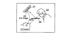
従来、立体画像表示装置に関する技術として、例えば、文献「3次元プロッタ手法を用いた臓器の立体表示及び生体との合成観察の試み」(映像情報(M)、Vol.26,No.20,p.1169)においては、図1に示すように、3次元立体表示装置21上に表示されたコンピュータによる画像生成に係るCG画像23と、観察者が肉眼22で見ている実像24とをハーフミラー25により重畳させて表示している。
【0003】
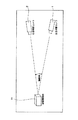
また、特開平9−147142号公報においては、図2に示すように、被観察物体31としての頭部の移動を検出するトラッキング手段としての位置・姿勢検出34及び決定手段35を用いれば、移動する視点に対応するコンピュータによる画像生成に係る画像を観察者32が見ている表示手段33上に生成することが可能になる技術が開示されている。
【0004】
ところで、一般に、コンピュータによる画像生成においては計算時間による時間的な遅れが生じる。
【0005】
また、表示装置上に表示されたCG画像と、観察者が肉眼で見ている像とを重畳させ表示するような場合においては、肉眼で見えている画像に対し遅れ時間に頭部が移動した分のずれ(ダイナミックレジストレーションエラー)が生じてしまう場合がある。
【0006】
また、画像の生成に時間がかかると、ライブ画像と生成画像との間のずれ(ダイナミックレジストレーションエラー)が大きくなり、使用上で支障をきたす場合がある。
【0007】
しかるに、コンピュータの処理能力には限界がある一方、表示画像に対しての要求は高解像度など複雑化の一途をたどっている。
【0008】
なお、文献「Improving Static and Dynamic Registration in an Optical See−through HMD Proceedings of SIGGRAPH ′94,pp.197−204」では、図3に示すように、頭部の動きを検出するセンサ40により検出された観察者の頭部41の位置姿勢情報をもとに、画像生成用コンピュータ42により視線に対応したCG画像を生成する際に、画像生成用コンピュータ42内において頭部の動きを予測し画像生成の時間遅れによるダイナミックレジストレーションエラーを少なくする試みがなされている。
【0009】
【発明が解決しようとする課題】
しかしながら、上述した図1及び図2に示すような従来の技術による手法において、両眼視差を用いた立体視を行った場合には、カメラ位置姿勢の計測計算を、左右視野のそれぞれに対して行う必要があるので、その計算に時間がかかると、それが2系統になるため、更なる時間の遅れを招く恐れがあった。
【0010】
また、上述した図3に示すような従来の技術による手法において、両眼視差を用いた立体視を行った場合には、予測を行うための計算を、左右視野のそれぞれに対して行う必要があるので、その予測計算に時間がかかると、それが2系統になるため、更なる時間の遅れを招く恐れがあった。
【0011】
本発明は、以上のような従来技術の不具合に鑑みてなされたもので、立体視を行う場合でも、時間遅れの少ない画像重畳システムとして構成される立体画像表示装置を提供することを目的とする。
【0012】
【課題を解決するための手段】
本発明によると、上記課題を解決するために、
(1) 観察対象を撮像する複数の撮像手段と、
上記複数の撮像手段の位置及び姿勢を各々検出する位置姿勢検出手段と、
上記観察対象の3次元データを保持するデータ保持手段と、
各撮像手段の位置及び姿勢に応じて上記3次元データより2次元画像を各々生成し、上記各撮像手段の撮像した各画像と重畳する画像重畳手段と、
を具備する立体画像表示装置において、
上記位置姿勢検出手段の各検出結果より、各撮像手段の相対的な位置及び姿勢を求める相対位置検出手段と、
上記上記相対位置検出手段によって求めた相対的な位置及び姿勢を用いて、一つの撮像手段の位置及び姿勢より他の撮像手段の位置及び姿勢を求める手段をさらに具備することを特徴とする立体画像表示装置が提供される。
【0013】
また、本発明によると、上記課題を解決するために、
(2) 撮像手段の位置及び姿勢より、所定時間後の撮像手段の位置及び姿勢を予測する予測手段をさらに具備し、
上記画像重畳手段は、上記予測手段で予測された各撮像手段の位置及び姿勢に応じて上記3次元データより2次元画像を各々生成することを特徴とする(1)記載の立体画像表示装置が提供される。
【0015】
【発明の実施の形態】
以下図面を参照して本発明の実施の形態について説明する。
【0016】
(第1の実施の形態)
図4は、本発明による立体画像表示装置の第1の実施の形態の構成を示すブロック図である。
【0017】
すなわち、この第1の実施の形態による立体画像表示装置は、次のように構成されている。
【0018】
図4において、参照符号1、2は、それぞれ左目用、右目用のライブ画像を入力するためのカメラ、
参照符号3は、被観察物体11の3次元モデルデータ格納部、
参照符号4は、左目用カメラ1の位置姿勢を検出するための左目用視野位置検出手段、
参照符号5は、右目用カメラ2の位置姿勢を検出するための右目用視野位置検出手段、
参照符号6は、左目用及び右目用視野位置検出手段4、5からの出力に基づいてカメラ1、2の相対対位置姿勢を求めるための相対位置検出手段、
参照符号7は、相対位置検出手段6からの相対位置データ及び左目用視野位置検出手段4からの左目用視野位置姿勢データに基づき、右目用の視野位置姿勢データを求める右目用視野位置計算手段、
参照符号8は、3次元モデルデータ格納部3の3次元モデルデータと左目用視野位置検出手段4及び右目用視野位置計算手段7からの左右の視野位置姿勢データに基づき、それぞれの視野に対応する画像データを再構成し、左目用及び右目用カメラ1、2からの左目用、右目用のライブ画像との重畳を行う画像再構成重畳手段、
参照符号9は、重畳された左右の画像データを立体画像表示するための画像表示手段である。
【0019】
次に、この第1の実施の形態による立体画像表示装置の作用を説明する。
【0020】
左目用及び右目用カメラ1、2は立体視をするための視差を得るため、通常、眼幅に相当する50mmから100mmの間隔をおいて配置されているが、この間隔を広く取ればそれだけ大きな視差を得ることができる。
【0021】
また、左目用及び右目用カメラ1、2は、図5に示すように、輻輳角Θと呼ばれる収束角度を持つことで、立体視を容易にするようになっている。
【0022】
この場合、被観察物体11が、視点の近くにある場合には輻輳角はより大きくした方が見やすいことが知られている。
【0023】
そのため、被観察物体11の位置による輻輳角や視差の大小による見易さを調整するために、カメラの設置幅、輻輳角については調整を行う場合がある。
【0024】
図4において、カメラ1、2からの画像データは、画像再構成重畳手段8に入力される。
【0025】
この画像再構成重畳手段8には、同時に、その時点のカメラ1、2の視野位置検出手段4、5の検出結果(L,R)及び3次元モデルデータ格納部3からの3次元モデルデータが入力され、それらに基づいて右目用、左目用のCG画像データが生成される。
【0026】
ここで、画像再構成重畳手段8は、3次元モデルデータ格納部3の3次元モデルデータと左目用視野位置検出手段4及び右目用視野位置計算手段7からの左右の視野位置姿勢データに基づき、それぞれの視野に対応する画像データを再構成することにより、右目用、左目用のCG画像データを生成したのち、左目用及び右目用カメラ1、2からの左目用、右目用のライブ画像との重畳を行う。
【0027】
そして、このようにして重畳された画像データは、画像表示手段9において立体視表示される。
【0028】
この状態において、観察者は、カメラ1、2の設置幅、輻輳角についての調整を行う。
【0029】
一旦、調整を行った後は、同じ被観察物体11を観察している間は再調整の必要がない。
【0030】
以上において、カメラ1、2の視野位置検出手段4、5の検出結果として与えられるL及びRは、各カメラの基準座標系の中での位置姿勢を表し、例えば、左目視野Lは次のように表記できる。
【0031】
ここで、座標系は直交座標系とし、基準座標としてG(X,Y,Z)を用いるものとする。
【0032】
【数1】

Rotはx,y,z軸回りの回転行列を、tx,ty,tzは基準座標の中での座標値を表す。
【0034】
カメラ1、2の視野位置検出にはトラッキング装置が用いられるが、例えば、赤外光を発光するLEDを複数個もち、これらを順に発光させ、それを複数個のCCDラインセンサで検出する方式などがある。
【0035】
しかし、複数個のLEDの発光、検出結果の計算、及び結果の通信などに数ms〜数10msの時間がかかる。
【0036】
画像表示手段9としてCRTなどを用いる場合には、そのリフレッシュレートは30ms程度であり、この検出による遅れは無視できない。
【0037】
上記調整が終わった状態の右目、左目視野用の座標値をそれぞれL0 ,R0 とする。
【0038】
ここで、両視野の相対的な関係はW=L0 /R0 として表される。
【0039】
この両視野の相対的な関係Wが求まった後は、右目用視野位置検出手段5を停止し、左目用視野位置検出手段4のみを働かせるようにする。
【0040】
この状態で、得られた左目用視野位置検出結果LにWを乗ずることにより、その時点での右目用視野位置検出結果Rを得ることができる。
【0041】
このL及びRを用いて、3次元モデルデータ格納部3から右目用、左目用の3次元モデルデータに基づきCG画像を生成する
このようにして生成されたCG画像にカメラ1、2からの画像信号が重畳されて画像表示手段9において立体視表示される。
【0042】
このことにより、調整時以外は視野位置検出手段4、5のうちのを1つだけ動作させれば良く、立体視を行う場合でも、時間遅れの少ない画像重畳システムを提供することが可能となる。
【0043】
なお、上述したようなこの第1の実施の形態の各構成は、当然、各種の変形、変更が可能である。
【0044】
例えば、右目用視野位置検出結果だけを用い、左目用視野位置を計算することもできる。
【0045】
また、多数のカメラを用い、同時に複数の視野の画像を入力する3次元計測装置などにおいても応用が可能である。
【0046】
(第2の実施の形態)
次に、本発明の第2の実施の形態を図6を用いて説明する。
【0047】
図6は、本発明による立体画像表示装置の第2の実施の形態の構成を示すブロック図である。
【0048】
すなわち、この第2の実施の形態による立体画像表示装置は、次のように構成されている。
【0049】
図6において、参照符号1、2は、それぞれ左目用、右目用のライブ画像を入力するためのカメラ、
参照符号3は、被観察物体11の3次元モデルデータ格納部、
参照符号4は、左目用カメラ1の位置姿勢を検出するための左目用視野位置検出手段、
参照符号5は、右目用カメラ2の位置姿勢を検出するための右目用視野位置検出手段、
参照符号10は、左目用視野位置検出手段4からの出力に基づいて左目用視野位置を予測する左目用視野位置予測手段、
参照符号6は、左目用及び右目用視野位置検出手段4、5からの出力に基づいてカメラ1、2の相対対位置姿勢を求めるための相対位置検出手段、
参照符号7は、相対位置検出手段6からの相対位置データ及び左目用視野位置検出手段4からの左目用視野位置姿勢データ並び左目用視野位置予測手段10からの出力に基づき、右目用の視野位置姿勢データを求める右目用視野位置計算手段、
参照符号8は、3次元モデルデータ格納部3の3次元モデルデータと左目用視野位置検出手段4及び右目用視野位置計算手段7からの左右の視野位置姿勢データに基づき、それぞれの視野に対応する画像データを再構成し、左目用及び右目用カメラ1、2からの左目用、右目用のライブ画像との重畳を行う画像再構成重畳手段、
参照符号9は、重畳された左右の画像データを立体画像表示するための画像表示手段である。
【0050】
次に、この第2の実施の形態による立体画像表示装置の作用を説明すると、左目用視野位置予測手段10を使用するか使用しないかが、上述した第1の実施の形態による立体画像表示装置の作用とことなり、基本的な作用は第1の実施の形態に準じている。
【0051】
したがって、ここでは第1の実施の形態の作用と異なる点のみについて説明するものとする。
【0052】
前述したように、被観察物体11の位置による輻輳角や視差の大小による見易さを調整するために、カメラの設置幅、輻輳角については調整を行う場合には、左目用視野位置予測手段10を使用しないで、相対位置検出手段6により左目用及び右目用視野位置検出手段4、5からの出力に基づいてカメラ1、2の相対位置姿勢検出を行うことにより、両視野の相対的な関係Wを求める。
【0053】
これは、眼幅、輻榛角の設定時においては、処理の時間遅れはあまり問題にならないため、左目用視野位置予測手段10を用いずに、左目用及び右目用視野位置検出手段4、5からの出力を用いて相対位置検出を行うことにより、両視野の相対的な関係Wを求めるようにしているものである。
【0054】
次に、調整を終了し、被観察物体11の観察を始める時点から、右目用視野位置検出手段5を停止し、左目用視野位置検出手段4からの出力Lを左目用視野位置予測手段10にへ入力させる。
【0055】
そして、左目用視野位置予測手段10においては、時間遅れの分の予測を行いL´を求める。
【0056】
この左目用視野位置予測手段10としては、カルマンフィルタ等を用い、速度、位置を推定する方法や、予測用に加速度センサなどを用意しその出力をあわせて用いる方法がある。
【0057】
次に、左目用視野位置予測手段10によって予測されたL´にWを乗ずることにより、右目視野位置の予測後の結果であるR´を得ることができる。
【0058】
このようにして得られたL´及びR´を用いて、第1の実施の形態と同様にして画像再構成重畳手段8に3次元モデルデータ格納部3からの3次元モデルデータに基づき右目用、左目用の画像データを生成することにより、画像表示手段9において立体視表示が可能となる。
【0059】
このことにより、調整時以外は視野位置検出手段4、5のうちのを1つだけ動作させれば良く、立体視を行う場合でも、時間遅れの少ない画像重畳システムを提供することが可能となる。
【0060】
なお、上述したようなこの第2の実施の形態の各構成は、当然、各種の変形、変更が可能である。
【0061】
例えば、右目用視野位置検出結果だけを用い、左目用視野位置を計算することもできる。
【0062】
また、多数のカメラを用い、同時に複数の視野の画像を入力する3次元計測装置などにおいても応用が可能である。
【0063】
そして、上述したような実施の形態で示した本明細書には、特許請求の範囲に示した請求項1乃至3以外にも、以下に付記1乃至付記2として示すような発明が含まれている。
【0064】
(付記1)視差を持った2系統の画像を入力する手段(1)、(2)と、
被観察物体(11)の3次元コンピュータグラフィクスモデル(3)とを備え、 該入力手段の位置姿勢を検出する手段(4)、(5)から検出された位置姿勢に基づき入力手段の視点位置からの視野を3次元モデル(3)に基づき再生し、入力手段(1)と(2)との相対関係を求めることで、観察時は位置姿勢検出手段(4)または(5)のみを使い視差を持った2系統の視点の位置姿勢を算出して3次元モデルを再構築し、2系統の入力手段による視差を持ったライブ画像を、再構成された3次元モデルに対して重畳して表示することを特徴とする立体画像表示装置。
【0065】
(作用)
入力手段の位置姿勢を検出する手段(4)、(5)から検出された位置姿勢に基づき、2つの入力手段の相対的関係(W)を求める。
【0066】
次に、左目用視野位置検出手段(4)の情報に基づき左目視点の位置姿勢(L)を求め、(L)に(W)を乗ずることで(5)の出力結果である右目視点の位置姿勢と等価な(R)が求まる。
【0067】
求まった(L)及び(R)に基づき視点からの画像の再構築を行う。
【0068】
(効果)
初期処理において2つの入力手段の位置姿勢の相対的関係(W)を求めることで、システムの稼動中は1つの検出手段ゝから両目に対応するそれぞれの視点の位置姿勢を計算でき、システムの高速化が図れる。
【0069】
(付記2)視差を持った2系統の画像を入力する手段(1)、(2)と、
被観察物体(11)の3次元コンピュータグラフィクスモデル(3)とを備え、 該入力手段の位置姿勢を検出する手段(4)、(5)から検出された位置姿勢に基づき入力手段の視点位置からの視野を3次元モデル(3)に基づき再生し、画像の表示時の位置姿勢を推定する位置予測手段(6)を備え、入力手段(1)と(2)との相対関係を求めることで、観察時は位置姿勢検出手段(4)及び位置予測手段(6)を使い視差を持った2系統の視点の位置姿勢を算出して3次元モデルを再構築し、2系統の入力手段による視差を持ったライブ画像を、再構成された3次元モデルに対して重畳して表示することを特徴とする立体画像表示装置。
【0070】
(作用)
入力手段の位置姿勢を検出する手段(4)、(5)から検出された位置姿勢に基づき、2つの入力手段の相対的関係(W)を求める。
【0071】
次に、左目用視野位置検出手段(4)の情報に基づき視点の位置姿勢(L)を求め、(L)を位置予測手段(6)に入力することによって、予測時点の位置姿勢(L´)を求める。
【0072】
次に、(L´)に(W)を乗ずることで右目視点の予測時点の位置姿勢(R´)が求まる。
【0073】
求まった(L´)及び(R´)に基づき視点からの画像の再構築を行う。
【0074】
(効果)
2つの入力手段の位置姿勢の相対的関係(W)を求め、1つの検出手段からの位置姿勢情報により予測時点の位置姿勢を推定することによって、もう一方の予測時点の位置姿勢が予測計算をすることなしに求められ、システムの高速化が図れる。
【0075】
【発明の効果】
従って、以上説明したように、本発明によれば、立体視を行う場合でも、時間遅れの少ない画像重畳システムとして構成される立体画像表示装置を提供することができる。
【図面の簡単な説明】
【図1】図1は、3次元立体表示装置21上に表示されたコンピュータによる画像生成に係るCG画像23と、観察者が肉眼22で見ている実像24とをハーフミラー25により重畳させて表示する従来の技術を示す図である。
【図2】図2は、被観察物体31としての頭部の移動を検出するトラッキング手段としての位置・姿勢検出34及び決定手段35を用いることにより、移動する視点に対応するコンピュータによる画像生成に係る画像を観察者32が見ている表示手段33上に生成する従来の技術を示す図である。
【図3】図3は、頭部の動きを検出するセンサ40により検出された観察者の頭部41の位置姿勢情報をもとに、画像生成用コンピュータ42により視線に対応したCG画像を生成する際に、画像生成用コンピュータ42内において頭部の動きを予測し画像生成の時間遅れによるダイナミックレジストレーションエラーを少なくする試みがなされている従来の技術を示す図である。
【図4】図4は、本発明による立体画像表示装置の第1の実施の形態の構成を示すブロック図である。
【図5】図5は、左目用及び右目用カメラ1、2が輻輳角Θと呼ばれる収束角度を持つことで、立体視を容易にするようになっていることを示す図である。
【図6】図6は、本発明による立体画像表示装置の第2の実施の形態の構成を示すブロック図である。
【符号の説明】
11…被観察物体、
1、2…左目用、右目用のライブ画像を入力するためのカメラ、
3…被観察物体11の3次元モデルデータ格納部、
4…左目用視野位置検出手段、
5…右目用視野位置検出手段、
6…相対位置検出手段、
7…右目用視野位置計算手段、
8…画像再構成重畳手段、
9…画像表示手段、
10…左目用視野位置予測手段。[0001]
BACKGROUND OF THE INVENTION
The present invention relates to a stereoscopic image display device, and in particular, detects the position and orientation of two systems of cameras having parallax, reconstructs a three-dimensional model of an object when the detected position and orientation are used as viewpoints, The present invention relates to a three-dimensional image display device that is displayed so as to be superimposed on each image from a system camera.
[0002]
[Prior art]
Conventionally, as a technique related to a stereoscopic image display device, for example, the document “Trial Display of Organs Using Three-Dimensional Plotter Method and Synthetic Observation with Living Body” (Video Information (M), Vol. 26, No. 20, p. 1169), as shown in FIG. 1, a
[0003]
In Japanese Patent Application Laid-Open No. 9-147142, as shown in FIG. 2, if a position /
[0004]
By the way, generally, in image generation by a computer, there is a time delay due to calculation time.
[0005]
In addition, in the case where the CG image displayed on the display device and the image that the observer sees with the naked eye are superimposed and displayed, the head moves in a delay time with respect to the image that is visible with the naked eye. There may be a minute shift (dynamic registration error).
[0006]
In addition, if it takes time to generate an image, a deviation (dynamic registration error) between the live image and the generated image becomes large, which may cause trouble in use.
[0007]
However, while the processing capability of computers is limited, the demand for display images is becoming increasingly complex, such as high resolution.
[0008]
In the document “Improving Static and Dynamic Registration in an Optical See-through HMD Processings of SIGGRAPH '94, pp. 197-204”, as shown in FIG. Based on the position and orientation information of the
[0009]
[Problems to be solved by the invention]
However, in the conventional technique as shown in FIGS. 1 and 2 described above, when stereoscopic viewing using binocular parallax is performed, measurement calculation of the camera position and orientation is performed for each of the left and right visual fields. Since it is necessary to perform the calculation, if the calculation takes time, there are two systems, which may cause a further time delay.
[0010]
Further, in the conventional technique as shown in FIG. 3 described above, when stereoscopic viewing using binocular parallax is performed, it is necessary to perform calculation for prediction on each of the left and right visual fields. Therefore, if it takes a long time for the prediction calculation, there are two systems, which may cause a further delay in time.
[0011]
The present invention has been made in view of the above-described problems of the prior art, and an object thereof is to provide a stereoscopic image display device configured as an image superimposing system with little time delay even when stereoscopic viewing is performed. .
[0012]
[Means for Solving the Problems]
According to the present invention, in order to solve the above problems,
(1) a plurality of imaging means for imaging an observation target;
Position and orientation detection means for detecting the position and orientation of each of the plurality of imaging means;
Data holding means for holding the three-dimensional data to be observed;
Image superimposing means for generating a two-dimensional image from the three-dimensional data according to the position and orientation of each imaging means, and superimposing each image captured by each imaging means;
In a stereoscopic image display device comprising:
From each detection result of the position and orientation detection means, relative position detection means for obtaining the relative position and orientation of each imaging means;
A stereoscopic image, further comprising means for obtaining the position and orientation of another imaging means from the position and orientation of one imaging means using the relative position and orientation obtained by the relative position detection means. A display device is provided.
[0013]
Further, according to the present invention, in order to solve the above problems,
(2) It further comprises a prediction means for predicting the position and orientation of the imaging means after a predetermined time from the position and orientation of the imaging means,
The stereoscopic image display apparatus according to (1), wherein the image superimposing unit generates a two-dimensional image from the three-dimensional data according to the position and orientation of each imaging unit predicted by the prediction unit. Provided.
[0015]
DETAILED DESCRIPTION OF THE INVENTION
Embodiments of the present invention will be described below with reference to the drawings.
[0016]
(First embodiment)
FIG. 4 is a block diagram showing the configuration of the first embodiment of the stereoscopic image display apparatus according to the present invention.
[0017]
That is, the stereoscopic image display apparatus according to the first embodiment is configured as follows.
[0018]
In FIG. 4,
[0019]
Next, the operation of the stereoscopic image display device according to the first embodiment will be described.
[0020]
The left-eye and right-
[0021]
Further, as shown in FIG. 5, the left-eye and right-
[0022]
In this case, it is known that when the observed
[0023]
Therefore, in order to adjust the vergence angle depending on the position of the
[0024]
In FIG. 4, the image data from the
[0025]
The image reconstruction superimposing means 8 simultaneously receives the detection results (L, R) of the visual field position detection means 4 and 5 of the
[0026]
Here, the image reconstruction superimposing means 8 is based on the three-dimensional model data in the three-dimensional model
[0027]
The image data superimposed in this way is displayed stereoscopically on the image display means 9.
[0028]
In this state, the observer adjusts the installation width and convergence angle of the
[0029]
Once the adjustment is made, there is no need for readjustment while the
[0030]
In the above, L and R given as detection results of the visual field position detection means 4 and 5 of the
[0031]
Here, the coordinate system is an orthogonal coordinate system, and G (X, Y, Z) is used as the reference coordinate.
[0032]
[Expression 1]
Rot represents a rotation matrix around the x, y and z axes, and tx, ty and tz represent coordinate values in the reference coordinates.
[0034]
A tracking device is used to detect the visual field position of the
[0035]
However, it takes several milliseconds to several tens of milliseconds for light emission of a plurality of LEDs, calculation of detection results, and communication of the results.
[0036]
When a CRT or the like is used as the image display means 9, the refresh rate is about 30 ms, and the delay due to this detection cannot be ignored.
[0037]
The adjustment is finished state right eye, and the coordinate values respectively L 0, R 0 for the left eye vision.
[0038]
Here, the relative relationship between the two fields of view is expressed as W = L 0 / R 0 .
[0039]
After the relative relationship W between the two visual fields is obtained, the right eye visual field position detecting means 5 is stopped and only the left eye visual field position detecting means 4 is operated.
[0040]
In this state, by multiplying the obtained left-eye visual field position detection result L by W, the right-eye visual field position detection result R at that time can be obtained.
[0041]
Using these L and R, a CG image is generated from the three-dimensional model
[0042]
Accordingly, only one of the visual field position detection means 4 and 5 needs to be operated except during the adjustment, and it is possible to provide an image superposition system with little time delay even when performing stereoscopic viewing. .
[0043]
It should be noted that each configuration of the first embodiment as described above can be variously modified and changed.
[0044]
For example, it is possible to calculate the left-eye visual field position using only the right-eye visual field position detection result.
[0045]
The present invention can also be applied to a three-dimensional measuring apparatus that uses a large number of cameras and inputs images of a plurality of fields of view at the same time.
[0046]
(Second Embodiment)
Next, a second embodiment of the present invention will be described with reference to FIG.
[0047]
FIG. 6 is a block diagram showing a configuration of the stereoscopic image display apparatus according to the second embodiment of the present invention.
[0048]
That is, the stereoscopic image display device according to the second embodiment is configured as follows.
[0049]
In FIG. 6,
[0050]
Next, the operation of the stereoscopic image display apparatus according to the second embodiment will be described. Whether the left eye visual field position prediction means 10 is used or not is determined according to the above-described stereoscopic image display apparatus according to the first embodiment. The basic operation is the same as that of the first embodiment.
[0051]
Therefore, only the points different from the operation of the first embodiment will be described here.
[0052]
As described above, in order to adjust the vergence angle according to the position of the
[0053]
This is because, when setting the eye width and the convergence angle, the processing time delay does not matter so much, and the left eye and right eye visual field position detection means 4, 5 are not used without using the left eye visual field position prediction means 10. The relative relationship W between the two fields of view is obtained by detecting the relative position using the output from.
[0054]
Next, when the adjustment is finished and the observation of the object to be observed 11 is started, the right eye visual field position detecting means 5 is stopped, and the output L from the left eye visual field position detecting means 4 is sent to the left eye visual field position predicting means 10. To input.
[0055]
Then, the left eye visual field position prediction means 10 performs prediction for the time delay to obtain L ′.
[0056]
As the visual field position prediction means 10 for the left eye, there are a method of estimating speed and position using a Kalman filter or the like, and a method of preparing an acceleration sensor for prediction and using the output together.
[0057]
Next, by multiplying L ′ predicted by the left eye visual field position prediction means 10 with W, R ′ that is a result after prediction of the right eye visual field position can be obtained.
[0058]
Using the L ′ and R ′ obtained in this way, the image reconstruction / superimposing means 8 is used for the right eye based on the 3D model data from the 3D model
[0059]
Accordingly, only one of the visual field position detection means 4 and 5 needs to be operated except during the adjustment, and it is possible to provide an image superposition system with little time delay even when performing stereoscopic viewing. .
[0060]
Of course, each configuration of the second embodiment as described above can be variously modified and changed.
[0061]
For example, it is possible to calculate the left-eye visual field position using only the right-eye visual field position detection result.
[0062]
The present invention can also be applied to a three-dimensional measuring apparatus that uses a large number of cameras and inputs images of a plurality of fields of view at the same time.
[0063]
In addition, the present specification shown in the embodiment as described above includes inventions as shown in
[0064]
(Appendix 1) Means (1), (2) for inputting two systems of images with parallax;
A three-dimensional computer graphics model (3) of the object to be observed (11), and detecting the position and orientation of the input means from the viewpoint position of the input means based on the position and orientation detected by the means (4) and (5) Is reproduced based on the three-dimensional model (3) and the relative relationship between the input means (1) and (2) is obtained, so that only the position / orientation detection means (4) or (5) is used during observation. 3D model is reconstructed by calculating the position and orientation of the viewpoints of the two systems with the image, and the live image with parallax from the two systems of input means is displayed superimposed on the reconstructed 3D model A stereoscopic image display device characterized by:
[0065]
(Function)
Based on the position and orientation detected from the means (4) and (5) for detecting the position and orientation of the input means, the relative relationship (W) between the two input means is obtained.
[0066]
Next, the position and orientation (L) of the left eye viewpoint is obtained based on the information of the visual field position detection means (4) for the left eye, and the position of the right eye viewpoint as the output result of (5) is obtained by multiplying (L) by (W). (R) equivalent to the posture is obtained.
[0067]
Based on the obtained (L) and (R), the image is reconstructed from the viewpoint.
[0068]
(effect)
By obtaining the relative relationship (W) between the positions and orientations of the two input means in the initial processing, the position and orientation of each viewpoint corresponding to both eyes can be calculated from one detection means 中 during the operation of the system. Can be achieved.
[0069]
(Appendix 2) Means (1), (2) for inputting two systems of images with parallax,
A three-dimensional computer graphics model (3) of the object to be observed (11), and detecting the position and orientation of the input means from the viewpoint position of the input means based on the position and orientation detected by the means (4) and (5) Is reproduced based on the three-dimensional model (3), and is provided with position prediction means (6) for estimating the position and orientation at the time of image display, and by obtaining the relative relationship between the input means (1) and (2). During observation, the position and orientation detection means (4) and the position prediction means (6) are used to calculate the position and orientation of two viewpoints having parallax, to reconstruct a three-dimensional model, and to produce parallax by the two systems of input means A three-dimensional image display device, wherein a live image having an image is superimposed and displayed on a reconstructed three-dimensional model.
[0070]
(Function)
Based on the position and orientation detected from the means (4) and (5) for detecting the position and orientation of the input means, the relative relationship (W) between the two input means is obtained.
[0071]
Next, the position and orientation (L) of the viewpoint is obtained based on the information of the left eye visual field position detecting means (4), and (L) is input to the position predicting means (6), whereby the position and orientation (L ' )
[0072]
Next, by multiplying (L ′) by (W), the position and orientation (R ′) at the prediction time of the right eye viewpoint can be obtained.
[0073]
Based on the obtained (L ′) and (R ′), the image is reconstructed from the viewpoint.
[0074]
(effect)
By calculating the relative relationship (W) between the position and orientation of the two input means and estimating the position and orientation at the predicted time from the position and orientation information from one detection means, the position and orientation at the other predicted time can be predicted. It is required without doing so, and the speed of the system can be increased.
[0075]
【The invention's effect】
Therefore, as described above, according to the present invention, it is possible to provide a stereoscopic image display device configured as an image superposition system with little time delay even when performing stereoscopic viewing.
[Brief description of the drawings]
FIG. 1 shows a
FIG. 2 is a diagram showing an example of image generation by a computer corresponding to a moving viewpoint by using a position /
FIG. 3 is a diagram illustrating the generation of a CG image corresponding to the line of sight by the image generation computer based on the position and orientation information of the observer's
FIG. 4 is a block diagram showing a configuration of a first embodiment of a stereoscopic image display apparatus according to the present invention.
FIG. 5 is a diagram showing that the left-eye and right-
FIG. 6 is a block diagram showing a configuration of a stereoscopic image display apparatus according to a second embodiment of the present invention.
[Explanation of symbols]
11 ... object to be observed,
1, 2 ... Camera for inputting live images for left eye and right eye,
3... 3D model data storage unit of the observed
4 ... Left eye visual field position detection means,
5 ... Visual field position detection means for the right eye,
6 ... Relative position detection means,
7: Right eye visual field position calculating means,
8: Image reconstruction superimposing means,
9: Image display means,
10: Visual field position prediction means for the left eye.
Claims (2)
上記複数の撮像手段の位置及び姿勢を各々検出する位置姿勢検出手段と、
上記観察対象の3次元データを保持するデータ保持手段と、
各撮像手段の位置及び姿勢に応じて上記3次元データより2次元画像を各々生成し、上記各撮像手段の撮像した各画像と重畳する画像重畳手段と、
を具備する立体画像表示装置において、
上記位置姿勢検出手段の各検出結果より、各撮像手段の相対的な位置及び姿勢を求める相対位置検出手段と、
上記相対位置検出手段によって求めた相対的な位置及び姿勢を用いて、一つの撮像手段の位置及び姿勢より他の撮像手段の位置及び姿勢を求める手段をさらに具備することを特徴とする立体画像表示装置。A plurality of imaging means for imaging the observation object;
Position and orientation detection means for detecting the position and orientation of each of the plurality of imaging means;
Data holding means for holding the three-dimensional data to be observed;
Image superimposing means for generating a two-dimensional image from the three-dimensional data according to the position and orientation of each imaging means, and superimposing each image captured by each imaging means;
In a stereoscopic image display device comprising:
From each detection result of the position and orientation detection means, relative position detection means for obtaining the relative position and orientation of each imaging means;
3D image display, further comprising means for obtaining the position and orientation of another imaging means from the position and orientation of one imaging means using the relative position and orientation obtained by the relative position detection means apparatus.
上記画像重畳手段は、上記予測手段で予測された各撮像手段の位置及び姿勢に応じて上記3次元データより2次元画像を各々生成することを特徴とする請求項1記載の立体画像表示装置。A prediction unit that predicts the position and orientation of the imaging unit after a predetermined time from the position and orientation of the imaging unit;
2. The stereoscopic image display apparatus according to claim 1, wherein the image superimposing unit generates a two-dimensional image from the three-dimensional data according to the position and orientation of each imaging unit predicted by the prediction unit.
Priority Applications (1)
| Application Number | Priority Date | Filing Date | Title |
|---|---|---|---|
| JP27306899A JP4144981B2 (en) | 1999-09-27 | 1999-09-27 | Stereoscopic image display device |
Applications Claiming Priority (1)
| Application Number | Priority Date | Filing Date | Title |
|---|---|---|---|
| JP27306899A JP4144981B2 (en) | 1999-09-27 | 1999-09-27 | Stereoscopic image display device |
Publications (2)
| Publication Number | Publication Date |
|---|---|
| JP2001103512A JP2001103512A (en) | 2001-04-13 |
| JP4144981B2 true JP4144981B2 (en) | 2008-09-03 |
Family
ID=17522709
Family Applications (1)
| Application Number | Title | Priority Date | Filing Date |
|---|---|---|---|
| JP27306899A Expired - Fee Related JP4144981B2 (en) | 1999-09-27 | 1999-09-27 | Stereoscopic image display device |
Country Status (1)
| Country | Link |
|---|---|
| JP (1) | JP4144981B2 (en) |
Families Citing this family (3)
| Publication number | Priority date | Publication date | Assignee | Title |
|---|---|---|---|---|
| DE102004022330B3 (en) * | 2004-05-06 | 2005-10-20 | Leica Microsystems Schweiz Ag | microscope |
| US8780185B2 (en) | 2009-11-25 | 2014-07-15 | Olympus Imaging Corp. | Image pickup apparatus having a display controlled using interchangeable lens information and/or finder information |
| JP5638791B2 (en) * | 2009-11-25 | 2014-12-10 | オリンパスイメージング株式会社 | Imaging device |
-
1999
- 1999-09-27 JP JP27306899A patent/JP4144981B2/en not_active Expired - Fee Related
Also Published As
| Publication number | Publication date |
|---|---|
| JP2001103512A (en) | 2001-04-13 |
Similar Documents
| Publication | Publication Date | Title |
|---|---|---|
| JP3745117B2 (en) | Image processing apparatus and image processing method | |
| JP3338618B2 (en) | Display method and display device for real space image and virtual space image | |
| US6570566B1 (en) | Image processing apparatus, image processing method, and program providing medium | |
| JP3728160B2 (en) | Depth image measuring apparatus and method, and mixed reality presentation system | |
| JP4933406B2 (en) | Image processing apparatus and image processing method | |
| TWI520576B (en) | Method and system for converting 2d images to 3d images and computer-readable medium | |
| US20060018509A1 (en) | Image generation device | |
| KR100911066B1 (en) | Image display system, image display method and recording medium | |
| US6608622B1 (en) | Multi-viewpoint image processing method and apparatus | |
| JPH07287761A (en) | Device and method for processing picture | |
| JPH11102438A (en) | Distance image generation device and image display device | |
| JP2008210276A (en) | Method and device for generating three-dimensional model information | |
| JP3032414B2 (en) | Image processing method and image processing apparatus | |
| JP2849313B2 (en) | Image recording and playback device | |
| JP6618260B2 (en) | Information processing apparatus, information processing method, and program | |
| CN110969706B (en) | Augmented reality device, image processing method, system and storage medium thereof | |
| JP3157483B2 (en) | Stereoscopic inspection apparatus and computer-readable recording medium storing stereoscopic inspection program | |
| JP2001256482A (en) | Device and method for generating parallax image | |
| JP4144981B2 (en) | Stereoscopic image display device | |
| WO2020185405A1 (en) | Registration of local content between first and second augmented reality viewers | |
| JPH06339454A (en) | Measuring endoscope device | |
| JPH09114979A (en) | Camera system | |
| JP2018078496A (en) | Three-dimensional moving picture display processing device, moving picture information recording medium, moving picture information provision server, and program | |
| JP3054312B2 (en) | Image processing apparatus and method | |
| JPH05266215A (en) | Picture display device |
Legal Events
| Date | Code | Title | Description |
|---|---|---|---|
| A621 | Written request for application examination |
Free format text: JAPANESE INTERMEDIATE CODE: A621 Effective date: 20050913 |
|
| A977 | Report on retrieval |
Free format text: JAPANESE INTERMEDIATE CODE: A971007 Effective date: 20080411 |
|
| A131 | Notification of reasons for refusal |
Free format text: JAPANESE INTERMEDIATE CODE: A131 Effective date: 20080422 |
|
| A521 | Written amendment |
Free format text: JAPANESE INTERMEDIATE CODE: A523 Effective date: 20080519 |
|
| TRDD | Decision of grant or rejection written | ||
| A01 | Written decision to grant a patent or to grant a registration (utility model) |
Free format text: JAPANESE INTERMEDIATE CODE: A01 Effective date: 20080610 |
|
| A01 | Written decision to grant a patent or to grant a registration (utility model) |
Free format text: JAPANESE INTERMEDIATE CODE: A01 |
|
| A61 | First payment of annual fees (during grant procedure) |
Free format text: JAPANESE INTERMEDIATE CODE: A61 Effective date: 20080617 |
|
| FPAY | Renewal fee payment (event date is renewal date of database) |
Free format text: PAYMENT UNTIL: 20110627 Year of fee payment: 3 |
|
| FPAY | Renewal fee payment (event date is renewal date of database) |
Free format text: PAYMENT UNTIL: 20120627 Year of fee payment: 4 |
|
| FPAY | Renewal fee payment (event date is renewal date of database) |
Free format text: PAYMENT UNTIL: 20120627 Year of fee payment: 4 |
|
| FPAY | Renewal fee payment (event date is renewal date of database) |
Free format text: PAYMENT UNTIL: 20130627 Year of fee payment: 5 |
|
| LAPS | Cancellation because of no payment of annual fees |