JP4144258B2 - Image output apparatus and image output method - Google Patents
Image output apparatus and image output method Download PDFInfo
- Publication number
- JP4144258B2 JP4144258B2 JP2002156273A JP2002156273A JP4144258B2 JP 4144258 B2 JP4144258 B2 JP 4144258B2 JP 2002156273 A JP2002156273 A JP 2002156273A JP 2002156273 A JP2002156273 A JP 2002156273A JP 4144258 B2 JP4144258 B2 JP 4144258B2
- Authority
- JP
- Japan
- Prior art keywords
- image
- display
- unit
- image data
- data
- Prior art date
- Legal status (The legal status is an assumption and is not a legal conclusion. Google has not performed a legal analysis and makes no representation as to the accuracy of the status listed.)
- Expired - Fee Related
Links
Images


Classifications
-
- H—ELECTRICITY
- H04—ELECTRIC COMMUNICATION TECHNIQUE
- H04N—PICTORIAL COMMUNICATION, e.g. TELEVISION
- H04N19/00—Methods or arrangements for coding, decoding, compressing or decompressing digital video signals
- H04N19/60—Methods or arrangements for coding, decoding, compressing or decompressing digital video signals using transform coding
- H04N19/61—Methods or arrangements for coding, decoding, compressing or decompressing digital video signals using transform coding in combination with predictive coding
-
- G—PHYSICS
- G09—EDUCATION; CRYPTOGRAPHY; DISPLAY; ADVERTISING; SEALS
- G09G—ARRANGEMENTS OR CIRCUITS FOR CONTROL OF INDICATING DEVICES USING STATIC MEANS TO PRESENT VARIABLE INFORMATION
- G09G5/00—Control arrangements or circuits for visual indicators common to cathode-ray tube indicators and other visual indicators
- G09G5/02—Control arrangements or circuits for visual indicators common to cathode-ray tube indicators and other visual indicators characterised by the way in which colour is displayed
- G09G5/026—Control of mixing and/or overlay of colours in general
Description
【0001】
【発明の属する技術分野】
PCアーキテクチャをベースとし、圧縮動画像と背景画像との合成を行う画像出力装置及び画像出力方法に関する。
【0002】
【従来の技術】
従来、PC(パーソナルコンピュータ)をベースとしたビデオ画像表示装置では、入力された圧縮動画像をビデオデコーダボードやグラフィックアクセラレータ等を利用してデコード処理し、デコード処理した動画像とそれ以外の画像とをグラフィック出力部で合成し、合成した画像を表示画像として表示装置に出力している。
【0003】
ここで、図6を用いて、上述のように画像を合成し、合成した画像を表示装置に出力する従来の装置(以下、画像出力装置2という。)について構成と動作を説明する。
【0004】
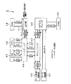
画像出力装置2は、図6に示すように、データ供給・格納部40と、データ供給部41と、サウスブリッジ42と、MPEGデコーダ43と、ノースブリッジ44と、RAM45と、CPU46と、グラフィック出力部47と、RAM48と、RAM49とを備えている。データ供給・格納部40は、サウスブリッジ42に接続されており、例えば、DVDドライブ、HDD、ネットワークモジュール、画像キャプチャーモジュール又はチューナーモジュール等の圧縮画像を含むデータを入出力する装置である。なお、複数台のデータ供給・格納部40がサウスブリッジ42に接続されていても良い。また、データ供給・格納部40は、例えばIEEE1394等のインターフェースを介してサウスブリッジ42に接続されていても良い。
【0005】
データ供給部41は、例えば、チューナーや外部入力モジュールであり、MPEGデコーダ43に接続されており、MPEGデコーダ43に圧縮画像を直接送信できるようになっている。サウスブリッジ42は、例えば、ICH(I/O Controller Hub)等のブリッジ又はハブであり、ノースブリッジ44及びMPEGデコーダ43が接続されている。サウスブリッジ42は、データ供給・格納部40から供給されてくるデータをノースブリッジ44及びMPEGデコーダ43に適合した所定の信号形式に変換し、変換後の信号をノースブリッジ44及びMPEGデコーダ43に出力する。MPEGデコーダ43は、サウスブリッジ42又はデータ供給装置から供給されたMPEGデータをデコードする。MPEGデコーダ43は、MPEGデコードデータをRAM49に出力する。RAM49は、MPEGデコーダ43から入力されたMPEGデコードデータを記憶する。RAM49に記憶されたMPEGデコードデータは、CPU46からの読み出し命令により読み出され、サウスブリッジ42に出力される。
【0006】
ノースブリッジ44は、例えば、MCH(Memory Controller Hub)等のブリッジ又はハブであり、RAM45と、CPU46と、グラフィック出力部47とに接続されている。ノースブリッジ44は、サウスブリッジ42から供給されてくるMPEGデータ、MPEGデコードデータ又はグラフィックデータ等を接続されている機器に適合した所定の信号形式に変換し出力する。CPU46は、画像出力装置2のメイン処理部として動作し、RAM45に記憶されているデータを読み出し、読み出したデータに所定の処理を行い、その処理結果をノースブリッジ44を介してグラフィック出力部47等に出力する。
【0007】
グラフィック出力部47は、ノースブリッジ44を介して入力されるデータに基づき表示部に適合した画像形式に変換して表示画像を生成し、表示部に出力する。なお、MPEGデコードデータに基づき生成される画像は、表示部の所定の場所に表示させるためにクロマキにより、キーカラーで塗りつぶした領域に表示される。
【0008】
【発明が解決しようとする課題】
上述したように、従来の画像出力装置2では、デコード処理したMPEGデータを表示画像に変換し、表示部に出力するために、MPEGデータをMPEGデコーダ43でデコード処理してからPCIバス等の接続線を介してサウスブリッジ42、ノースブリッジ44を経てグラフィック出力部47に供給する必要があった。
【0009】
したがって、デコード処理したMPEGデータがHDTV(High Definition Television)クラスの大容量データの場合には、MPEGデコーダ43サウスブリッジ42間のバスが帯域不足になる問題がある。
【0010】
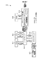
また、上記問題点を解決するために、図7に示すように、データ供給部41から供給されたMPEGデータのデコード処理の一部をCPU46により行い、一部処理後のMPEGデータをMPEGデコード支援演算器を有したグラフィック出力部50に供給し、グラフィック出力部50で残りのデコード処理を行う構成にした場合には、一部のデコード処理をCPU46が行うことによるCPU46の負荷が増加し、かつ一部処理後のMPEGデータをノースブリッジ44からグラフィック出力部50へ供給する際に、ノースブリッジ44グラフィック出力部47間のバスの帯域を消費する問題がある。
【0011】
さらに、上述したように、MPEGデコードデータにより表される第1の表示画像を表示部に表示する際、上記第1の表示画像は、所定のキーカラーで塗りつぶした領域に表示されるため、第1の表示画像の上面にMPEGデータ以外の画像データにより表される第2の表示画像が重なった場合、図5(a)に示すように、上記キーカラーと第2の表示画像で使用されている色とが同一の部分において、後面の第1の表示画像が前面に表示される現象が起こる問題がある。
【0012】
そこで、本発明では、MPEGデコーダ−サウスブリッジ間及びサウスブリッジ−ノースブリッジ間及びノースブリッジ−グラフィック出力部間のバスにかかる負担を軽減し、かつ第1の表示画像と第2の表示画像とが重なり合う部分において、後面の第1の表示画像が前面の第2の表示画像に表示されてしまうという現象を起こすことなく表示画像の合成を行うことが可能な画像出力装置及び画像出力方法を提供することを目的とする。
【0013】
【課題を解決するための手段】
本発明に係る画像出力装置は、上述の問題を解決するために、入力された圧縮画像を含む符号化動画像データから第1の画像データを復号する復号手段、及び、上記第1の画像データと第2の画像データとを合成し、合成した表示画像を表示部に出力する合成出力手段を備える復号/合成部と、入力されたデータを一時記憶する記憶部と、上記復号/合成部に備えられた上記復号手段により復号された上記第1の画像データを上記表示部に表示する際、上記表示部の指定された場所に任意の大きさで上記第1の画像データにより表される第1の表示画像が表示される表示領域を示す第1の表示領域情報を生成する第1の表示領域情報生成手段、及び、上記表示部の指定された場所に任意の大きさで上記第2の画像データにより表される第2の表示画像が表示される表示領域を示す第2の表示領域情報を生成する第2の表示領域情報生成手段として機能する演算処理部と、上記記憶部により一時記憶されたデータに含まれている画像データに基づき上記表示部に適合した画像形式の上記第2の画像データを生成する表示画像生成手段、及び、上記第1の画像データと上記第2の画像データとを合成する際に、上記第1の表示画像と上記第2の表示画像が重なって表示される場合、上記第1の表示領域情報と上記第2の表示領域情報及び上記第1の画像データと上記第2の画像データの位置関係に基づき、合成パラメータを生成する合成パラメータ生成手段を備え、上記合成パラメータ生成手段は、上記第1の画像データによる第1の表示画像が前面で、上記第2の画像データによる第2の表示画像が後面の場合には、上記合成パラメータを透明に調整し、上記第2の画像データによる第2の表示画像が前面で、上記第1の画像データによる第1の表示画像が後面の場合には、上記合成パラメータを不透明に調整し、上記合成パラメータ生成手段により生成した合成パラメータを上記表示画像生成手段により生成した第2の画像データに付加して出力するグラフィック出力部とを備え、上記グラフィック出力部と上記復号/合成部との間がバスで接続され、上記グラフィック出力部から上記合成パラメータが付加された上記第2の表示画像を上記復号/合成部に供給し、上記復号/合成部において、上記記復号手段により復号された上記第1の表示画像と上記第2の表示画像とを上記合成出力手段により上記第2の表示画像に付加されている上記合成パラメータに基づき合成し、合成した表示画像を上記表示部に出力することを特徴とする。
また、本発明に係る画像出力方法は、入力された圧縮画像を含む符号化動画像データから復号された第1の画像データを表示部に表示する際、上記表示部の指定された場所に任意の大きさで上記第1の画像データにより表される第1の表示画像が表示される表示領域を示す第1の表示領域情報を生成し、入力されたデータに含まれている画像データに基づき上記表示部に適合した画像形式の第2の画像データを生成し、入力された第2の画像データを上記表示部に表示する際、上記第2の画像データを表示される表示領域を示す第2の表示領域情報を生成し、上記表示部の指定された場所に任意の大きさで上記第2の画像データにより表される第2の表示画像が表示される表示領域を示す第2の表示領域情報を生成し、上記第1の画像データと上記第2の画像データとを合成する際に、上記第1の表示画像と上記第2の表示画像が重なって表示される場合、上記第1の表示領域情報と上記第2の表示領域情報及び上記第1の画像データと上記第2の画像データの位置関係に基づき、合成パラメータを生成し、上記第1の画像データによる第1の表示画像が前面で、上記第2の画像データによる第2の表示画像が後面の場合には、上記合成パラメータを透明に調整し、上記第2の画像データによる第2の表示画像が前面で、上記第1の画像データによる第1の表示画像が後面の場合には、上記合成パラメータを不透明に調整して、上記合成パラメータを上記第2の画像データに付加し、上記第2の表示画像に付加されている上記合成パラメータに基づき、上記第1の画像データと上記第2の画像データとを合成し、合成した表示画像を上記表示部に出力することを特徴とする。
【0014】
【発明の実施の形態】
以下、本発明の実施の形態について図面を参照しながら詳細に説明する。
【0015】
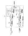
本発明は、例えば図1に示すような画像出力装置1に適用される。画像出力装置1は、表示画像を表示部に出力する装置であり、データ供給部10と、データ格納部11と、サウスブリッジ12と、MPEGデコーダ/画像合成部13と、RAM14と、ノースブリッジ15と、RAM16と、CPU17と、グラフィック出力部18と、RAM19とを備える。画像出力装置1は、MPEGデコーダ/画像合成部13でデータ供給部10から供給されたMPEGデータをデコードし、CPU17で上記表示部の指定された場所に任意の大きさで上記デコード後のMPEGデータ(以下、MPEGデコードデータという。)により表される第1の表示画像を表示させる第1の表示領域情報を生成し、また、RAM16にグラフィックデータを含むデータを一時記憶し、グラフィック出力部18でRAM16から読み出したグラフィックデータに基づき上記表示部に適合した画像形式である第2の表示画像を生成し、CPU17で上記表示部の指定された場所に任意の大きさで第2の表示画像を表示させる第2の表示領域情報を生成し、かつ上記第1の表示画像と上記第2の表示画像とを合成する際に、上記第1の表示領域情報と上記第2の表示領域情報に基づき、合成状態を決定する合成パラメータ(以下、アルファプレーン情報という。)を生成し、グラフィック出力部18で上記第2の表示画像に上記アルファプレーン情報を付加する。また、画像出力装置1は、グラフィック出力部18とMPEGデコーダ/画像合成部13とが接続線で接続されており、上記接続線を介してグラフィック出力部18からMPEGデコーダ/画像合成部13にアルファプレーン情報付きの第2の表示画像が供給され、MPEGデコーダ/画像合成部13で上記アルファプレーン情報に基づき、上記第1の表示画像と上記第2の表示画像とを合成し、合成した表示画像を上記表示部に出力する。
【0016】
以下に、上述した画像出力装置1の構成と動作について詳述する。データ供給部10は、例えば、DVDドライブ、ネットワークモジュール、画像キャプチャーモジュール又はチューナーモジュール等の圧縮画像を含むデータを入出力する装置であり、サウスブリッジ12及びMPEGデコーダ/画像合成部13に接続されている。データ供給部10は、サウスブリッジ12を介してMPEGデコーダ/画像合成部13及びノースブリッジ15にMPEGデータ等を供給しても良いし、MPEGデコーダ/画像合成部13に直接、MPEGデータを供給しても良い。なお、複数台のデータ供給部10がサウスブリッジ12に接続されていても良い。また、データ供給部10は、例えばIEEE1394等のインターフェースを介してサウスブリッジ12に接続されていても良い。
【0017】
データ格納部11は、例えば、HDDやDVDレコーダ等であり、サウスブリッジ12に接続されている。データ格納部11は、サウスブリッジ12を介してMPEGデータを記録する。サウスブリッジ12は、例えば、ICH(I/O Controller Hub)等のブリッジ又はハブであり、データ格納部11、データ供給部10、ノースブリッジ15及びMPEGデコーダ/画像合成部13が接続されている。サウスブリッジ12は、データ供給部10から供給されるグラフィックデータ及びMPEGデータ等を所定の信号形式に変換し、ノースブリッジ15及びMPEGデコーダ/画像合成部13に供給する。
【0018】
MPEGデコーダ/画像合成部13は、例えば、DSPであり、データ供給部10、サウスブリッジ12、RAM14及びグラフィック出力部18が接続されており、データ供給部10から供給されたMPEGデータ又はサウスブリッジ12を介して供給されたMPEGデータをデコード処理する。また、MPEGデコーダ/画像合成部13は、グラフィック出力部18から第2の表示画像とともに供給されるアルファプレーン情報に基づき、MPEGデコードデータにより表される第1の表示画像と第2の表示画像とを合成処理し、合成した表示画像を表示部に出力する。また、MPEGデコーダ/画像合成部13は、MPEGデコードデータ及び合成処理した表示画像をRAM14に出力する。なお、表示部に表示される第1の表示画像及び第2の表示画像は、CPU17で生成された表示領域情報に基づき、指定された場所に任意の大きさで表示される。
【0019】
RAM14は、例えば、DRAMであり、MPEGデコーダ/画像合成部13でデコード処理されたMPEGデコードデータや、合成処理された合成画像を記憶保持する。RAM14に記憶された上記合成画像は、表示部に出力され表示される。なお、RAM14は、MPEGデコーダ/画像合成部13により使用されるデータを記憶保持することができるものであればSDRAM等でも良い。
【0020】
ノースブリッジ15は、例えば、MCH(Memory Controller Hub)等のブリッジ又はハブであり、サウスブリッジ12、RAM16、CPU17及びグラフィック出力部18に接続されている。ノースブリッジ15は、サウスブリッジ12から供給されるグラフィックデータ及びMPEGデータ等を所定の信号形式に変換し、RAM16及びCPU17に供給する。RAM16は、例えば、SDRAMであり、ノースブリッジ15に接続されており、画像出力装置1のメインメモリとして動作し、画像出力装置1で利用されるさまざまなデータの記憶保持を行う。なお、RAM16は、画像出力装置1のメインメモリとして利用できるモジュールであればRDRAM等でも良い。CPU17は、ノースブリッジ15に接続されており、画像出力装置1のメイン処理部として動作し、RAM16に記憶されているデータを読み出し、読み出したデータに所定の処理を行い、その処理結果をノースブリッジ15を介してグラフィック出力部18等に出力する。また、CPU17は、グラフィック出力部18で表示画像の合成を行う際に用いるアルファプレーン情報を生成し、生成したアルファプレーン情報をグラフィック出力部18に出力する。なお、アルファプレーン情報の生成の方法については後述する。
【0021】
グラフィック出力部18は、例えば、グラフィック・アクセラレータであり、ノースブリッジ15、RAM19及びMPEGデコーダ/画像合成部13に接続されており、ノースブリッジ15を介して供給されたグラフィックデータに基づき、所定の画像形式である表示画像を生成し、生成した上記表示画像とアルファプレーン情報を混合し、アルファプレーン情報付の表示画像をMPEGデコーダ/画像合成部13に供給する。また、グラフィック出力部18は、アルファプレーン情報付の表示画像の処理や保持のためにRAM19を利用する。なお、グラフィック出力部18は、グラフィックデータに基づき所定の画像形式である表示画像を生成でき、生成した表示画像とアルファプレーン情報を混合でき、かつMPEGデコーダ/画像合成部13に出力できる構成のものであればグラフィック・アクセラレータ以外でも良い。
【0022】
RAM19は、例えば、DDRであり、グラフィック出力部18に接続されており、グラフィック出力部18で使用されるデータの記憶保持を行う。なお、RAM19は、グラフィック出力部18が使用するデータの記憶保持ができるモジュールであればSDRAM等でも良く、また、RAM16を代用しても良い。この場合、RAM19の分のコストが抑えられ、装置全体のコストダウンとなる。
【0023】
ここで、MPEGデコーダ/画像合成部13の画像合成動作について説明する。MPEGデコーダ/画像合成部13は、上述したようにサウスブリッジ12又はデータ供給部10から供給されたMPEGデータをデコード処理し、MPEGデコードデータを生成し、MPEGデコードデータに基づき表示部に適合した画像形式である第1の表示画像を生成する。一方、グラフィック出力部18は、上述したようにノースブリッジ15からグラフィックデータが供給され、上記グラフィックデータに基づき表示部に適合した画像形式である第2の表示画像を生成する。CPU17は、上記MPEGデコードデータにより表される第1の表示画像及び上記グラフィックデータにより表される第2の表示画像をそれぞれ表示部の指定された場所に任意の大きさで表示させるための表示領域情報を生成し、生成した表示領域情報をMPEGデコーダ/画像合成部13に供給する。また、CPU17は、所定の階調値を有するアルファプレーン情報を1画面分生成し、上記アルファプレーン情報をグラフィック出力部18に供給する。グラフィック出力部18は、上記アルファプレーン情報と上記第2の表示画像とを合成し、アルファプレーン情報付きの第2の表示画像をMPEGデコーダ/画像合成部13に供給する。
【0024】
MPEGデコーダ/画像合成部13は、アルファプレーン情報に基づき第1の表示画像と第2の表示画像とを合成し、合成した表示画像を表示領域情報に応じて表示部に出力する。
【0025】
この例で説明しているアルファプレーン情報は、第2の表示画像に付属する情報であり、例えば、第2の表示画像に付属するアルファプレーン情報において透明度を「α」とすると、表示部に表示される色の情報「C」は、第1の表示画像の色情報「C1」と、第2の表示画像の色情報「C2」とを用いて、
C=C1×(1−α)+C2×α
で表すことができる。なお、αは、0≦α≦1であり、例えば、α=0の時、アルファプレーン情報が付属する画像(第2の表示画像)の中でα=0となっているピクセル部分が完全に透明であると仮定し、α=1で完全に不透明であると仮定する。
【0026】
上記では、式を簡単にするため、色情報「C」を用いたが、実際にはR、G、Bや輝度、クロマ等といったピクセル情報が用いられる。また、アルファプレーン情報は、画面の3次元座標上での前後関係(Z軸方向)とは別に独立して考えることができ、例えば、図2(a)の「T」で示した領域のアルファプレーン情報が「α=0(透明)」となっていた場合、「T」の領域には背後の情報である第1の表示画像が合成され出力される。なお、より高度な画面表示を行うために、第1の表示画像もアルファプレーン情報を持っていても良い。
【0027】
CPU17は、図2(b)に示すように、第1の表示画像と第2の表示画像とが重なり合う部分において、最終的に表示部に表示される画像で、表示されている画像が「前面」であると定義した場合(前述したように、実際の画面の前後関係はアルファプレーン情報とは独立して与えることが出来るが、表示部に表示される2次元の画像の見え方はアルファプレーン情報によって変化するので、見かけ上前面に見える部分を「前面」と表現する)、第1の表示画像が前面となり、第2の表示画像が後面となる場合には、例えば、アルファプレーン情報の第1の表示画像領域を「透明」に調整する。また、図2(c)第2の表示画像が前面となり、第1の表示画像が後面となる場合には、例えば、アルファプレーン情報の第2の表示画像領域を「不透明」に調整する。
【0028】
また、MPEGデコーダ/画像合成部13は、例えば、図3に示すような、第1のウィンドウ拡縮制御部30と、アルファプレーン情報抽出部31と、第1の制御回路部32と、ビデオデコーダ部33と、第2のウィンドウ拡縮制御部34と、第2の制御回路部35と、表示画像合成部36とを備える構成であっても良い。
【0029】
アルファプレーン情報付きの第2の表示画像が第1のウィンドウ拡縮制御部30に入力される。第1のウィンドウ拡縮制御部30は、第2の表示画像が表示部に表示される際の大きさ及び位置を制御し、アルファプレーン情報抽出部31に出力する。アルファプレーン情報抽出部31は、第2の表示画像からアルファプレーン情報を抽出する。抽出されたアルファプレーン情報は、第1の制御回路部32と第2の制御回路部35とに供給される。第1の制御回路部32は、第2の表示画像に所定の制御を行い、制御後の第2の表示画像を表示画像合成部36に出力する。
【0030】
ビデオデコーダ部33は、入力されるMPEGデータをデコード処理し、第1の表示画像を生成し、上記第1の表示画像を第2のウィンドウ拡縮制御部34に出力する。第2のウィンドウ拡縮制御部34は、第1の表示画像が表示部に表示される際の大きさ及び位置を制御し、制御後の第1の表示画像を第2の制御回路部35に出力する。第2の制御回路部35は、第1の表示画像に所定の制御を行い、制御後の第1の表示画像を表示画像合成部36に出力する。表示画像合成部36は、第1の表示画像と第2の表示画像を合成し、表示部に出力する。
【0031】
なお、上記のように、第1の表示画像および第2の表示画像を処理するウィンドウ拡縮制御部34が存在するため、第1の表示画像の領域サイズと第2の表示画像の領域サイズは、表示部で最終的に表示に用いられる領域サイズと一致していなくても良い。
【0032】
また、第1の制御回路部32は第2の表示画像とこれに付属するアルファプレーン情報である係数「α」とから第2の表示画像を制御し、第2の制御回路部35は、第1の表示画像と、係数「1−α」とによって第1の表示画像を制御する。
【0033】
つぎに、アルファプレーン情報の生成について図4に示すフローチャートを用いて説明する。
【0034】
ステップST1において、CPU17は、アルファプレーン情報の生成処理を継続するかどうかの判定を行う。CPU17は、MPEGデコーダ/画像合成部13が合成画像の出力を表示部に対して行わない場合には、アルファプレーン情報の生成処理を終了し、MPEGデコーダ/画像合成部13が合成画像の出力を表示部に対して継続する場合にはステップST2に進む。
【0035】
ステップST2において、CPU17は、第1の表示画像と第2の表示画像との前面/後面の順位等の位置関係が前回処理した後に更新されているかどうかを判断する。
【0036】
ステップST3において、CPU17は、上記ステップST2の判断により、第1の表示画像と第2の表示画像との前面/後面の順位等の位置関係が前回と変わらない(更新されていない)場合にはステップST1に戻り、第1の表示画像と第2の表示画像との前面/後面の順位等の位置関係が前回の処理から変化している(更新されている)場合にはステップST4に進む。なお、初めて処理を開始した場合には、ステップST4に進むこととする。また、ステップST2〜ステップST3の処理を行うことにより、それぞれの領域が移動していない場合に、CPU17で処理されるデータ量を減少させることができ、また、負荷を減らすことができる。
【0037】
ステップST4において、CPU17は、出力する1画面分のアルファプレーン情報が生成されたかどうかを判断する。1画面分のアルファプレーン情報が生成されたと判断した場合には、ステップST1に戻り、1画面分のアルファプレーン情報が生成されていないと判断した場合には、未処理のピクセルについてアルファプレーン情報の生成を継続するため、ステップST5に進む。
【0038】
ステップST5において、CPU17は、第1の表示画像と第2の表示画像との前面/後面の順位を計算する。この前面/後面というのは、前述したように、3次元上での画面の位置関係ではなく、表示部での見え方である。現在判定しているピクセルに図1に示したMPEGデコーダ/画像合成部13で得られる画像を表示部に表示する場合、処理しているピクセルのアルファプレーン情報の値を階調値0(透明)に調整する。また、グラフィック出力部18から得られる画像を表示部に表示したい場合は、255(不透明)に調整する。なお、この例でのアルファプレーン情報は、0(透明)〜255(不透明)の256階調とし、表示したい透明度に応じてこの中間値をとることができる。この処理の終了後、ステップST4に戻る。
【0039】
上述のような処理を行うことでアルファプレーン情報の生成が行われる。MPEGデコーダ/画像合成部13では、上記アルファプレーン情報の階調値に基づき第1の表示画像と第2の表示画像との合成を行い、合成画像を表示部に出力する。
【0040】
したがって、本発明に係る画像出力装置1に備えられているグラフィック出力部18は、MPEGデータ以外のグラフィックデータや、上記グラフィックデータにより表される第2の表示画像を表示部に表示するための各種のコマンドや、上述したアルファプレーン情報等のデータを処理し、アルファプレーン情報付きの表示画像を生成し、生成したアルファプレーン情報付きの表示画像をMPEGデコーダ/画像合成部13に供給する。従来の画像出力装置の場合、グラフィック出力部18と表示部とが接続線で接続され、上記接続線を介してグラフィック出力部18から表示部に表示画像を出力していたが、本発明では、グラフィック出力部18とMPEGデコーダ/画像合成部13とが接続線で接続され、上記接続線を介してグラフィック出力部18からMPEGデコーダ/画像合成部13にアルファプレーン情報付きの表示画像を供給し、MPEGデコーダ/画像合成部13から表示画像を表示部に出力する。
【0041】
ここで、従来の画像出力装置による表示画像の合成処理と本発明に係る画像出力装置1による表示画像の合成処理とを図5を用いて比較する。従来の画像出力装置では、図5(a)に示すように、第1の表示画像が後面で第2の表示画像が前面の場合において、第1の表示画像と第2の表示画像の合成時に、比較回路により第2の表示画像に使用されている色とキーカラーとの差分を与えるので、第1の表示画像のキーカラーと第2の表示画像のA領域に使用されている色とが同一のときには、第1の表示画像が第2の表示画像のA領域の部分に表示されてしまう。一方、本発明に係る画像出力装置では、図5(b)に示すように、上記図3に示した構成となっているので、後面である第1の表示画像が前面である第2の表示画像上に表示されることはない。
【0042】
このように構成された画像出力装置1では、グラフィック出力部18とMPEGデコード間をバスで接続し、グラフィック出力部18からグラフィックデータにより表されるアルファプレーン情報付きの第2の表示画像をMPEGデコーダ/画像合成部13に供給し、MPEGデコーダ/画像合成部13によりMPEGデコードデータにより表される第1の表示画像と上記第2の表示画像とをアルファプレーン情報に基づき合成し、合成した表示画像を表示部に出力するので、MPEGデコード−サウスブリッジ12間又はノースブリッジ15グラフィック出力部18間の接続線にかかる負担が軽減され、かつ第1の表示画像と第2の表示画像とが重なり合う部分において、後面の第1の表示画像が前面の第2の表示画像上に表示される現象を起こすことなく表示画像の合成を行うことができる。さらに、画像出力装置1では、MPEGデータのデコード処理をMPEGデコーダ/画像合成部13のみで行うため、CPU17の負荷を軽減することが可能である。
【0043】
なお、本発明に係る画像出力装置1では、グラフィックデータ及びMPEGデータに加えて、プログラムやプログラムが扱うデータの他、様々な制御信号が接続線を介して各機器間で送受信される。また、上述した第1の表示画像及び第2の表示画像は、RGB信号又はYUV信号その他の表色系で表示部に出力される。さらに、本発明に係る画像出力装置1は、例えば、パーソナルコンピュータ(PC、Personal Computer)、携帯情報端末、パーソナルビデオレコーダ(PVR、Personal Video Recorder)又はセットトップボックス(STB、Set Top Box)等に適用される。
【0044】
【発明の効果】
以上詳細に説明したように、本発明によれば、入力された圧縮画像を含む符号化動画像データから第1の画像データを復号する復号手段、及び、上記第1の画像データと第2の画像データとを合成し、合成した表示画像を表示部に出力する合成出力手段を備える復号/合成部とバスで接続されたグラフィック出力部において、記憶部により一時記憶された入力されたデータに含まれている画像データに基づき上記表示部に適合した画像形式の第2の画像データを表示画像生成手段により生成し、第1の表示領域情報生成手段、及び、第2の表示領域情報生成手段として機能する演算処理部により生成される表示部の指定された場所に任意の大きさで第1の画像データにより表される第1の表示画像が表示される表示領域を示す第1の表示領域情報と上記表示部の指定された場所に任意の大きさで第2の画像データにより表される第2の表示画像が表示される表示領域を示す第2の表示領域情報及び上記第1の画像データと上記第2の画像データの位置関係に基づき、合成パラメータ生成手段により合成パラメータを生成し、上記第1の画像データによる表示画像が前面で、上記第2の画像データによる表示画像が後面の場合には、上記合成パラメータを透明に調整し、上記第2の画像データによる表示画像が前面で、上記第1の画像データによる表示画像が後面の場合には、上記合成パラメータを不透明に調整し、上記合成パラメータ生成手段により生成した合成パラメータを上記表示画像生成手段により生成した第2の画像データに付加し、上記合成パラメータを付加した上記第2の画像データが供給される上記復号/合成部において、上記記復号手段により復号された上記第1の画像データと上記第2の画像データとを上記合成出力手段により上記第2の画像データに付加されている上記合成パラメータに基づき合成し、合成した表示画像を上記表示部に出力するので、大容量の第1の画像データを当該画像出力装置内の接続線以外の接続線に負担をかけて移動させることがないため、接続線の負担を軽減することができ、しかも、合成パラメータに基づき第1の画像データと上記第2の画像データとを合成するので、第1の画像データによる表示画像と第2の画像データによる表示画像とが重なり合う部分において、後面の第1の画像データによる表示画像が前面の第2の画像データによる表示画像上に表示される現象を起こすことなく表示画像の合成を行うことができる。
【図面の簡単な説明】
【図1】本発明を適用した画像出力装置の構成を示すブロック図である。
【図2】第1の表示画像と第2の表示画像とを合成し(a)、第1の表示画像が前面で第2の表示画像が後面の場合(b)と、第2の表示画像が前面で第1の表示画像が後面の場合(c)の合成画像を示す模式図である。
【図3】本発明を適用した画像出力装置が備えているMPEGデコーダ/画像合成部の構成を示すブロック図である。
【図4】本発明を適用した画像出力装置が備えているCPUによりアルファプレーン情報を生成する動作を示すフローチャートである。
【図5】従来の画像出力装置による合成処理(a)と、本発明に係る画像出力装置による合成処理(b)とを比較した図である。
【図6】従来の画像出力装置の第1の構成例を示すブロック図である。
【図7】従来の画像出力装置の第2の構成例を示すブロック図である。
【符号の説明】
1 画像出力装置、10 データ供給部、11 データ格納部、12 サウスブリッジ、13 MPEGデコーダ/画像合成部、14,16,19 RAM、15 ノースブリッジ、17 CPU、18 グラフィック出力部、30 第1のウィンドウ拡縮制御部、31 アルファプレーン情報抽出部、32 第1の制御回路部、33 ビデオデコーダ部、34 第2のウィンドウ拡縮制御部、35第2の制御回路部、36 表示画像合成部[0001]
BACKGROUND OF THE INVENTION
An image output device based on a PC architecture that synthesizes a compressed video and a background image And image output method About.
[0002]
[Prior art]
Conventionally, in a video image display device based on a PC (personal computer), an input compressed moving image is decoded using a video decoder board, a graphic accelerator or the like, and the decoded moving image and other images are decoded. Are synthesized by the graphic output unit, and the synthesized image is output to the display device as a display image.
[0003]
Here, the configuration and operation of a conventional apparatus (hereinafter referred to as an image output apparatus 2) that combines images as described above and outputs the combined image to a display device will be described with reference to FIG.
[0004]
As shown in FIG. 6, the
[0005]
The
[0006]
The
[0007]
The
[0008]
[Problems to be solved by the invention]
As described above, in the conventional
[0009]
Therefore, when the decoded MPEG data is large-capacity data of HDTV (High Definition Television) class, there is a problem that the bus between the
[0010]
Further, in order to solve the above problems, as shown in FIG. 7, a part of the decoding process of the MPEG data supplied from the
[0011]
Further, as described above, when the first display image represented by the MPEG decoded data is displayed on the display unit, the first display image is displayed in an area painted with a predetermined key color. When a second display image represented by image data other than MPEG data overlaps the upper surface of one display image, as shown in FIG. 5A, the key color and the second display image are used. There is a problem that a phenomenon occurs in which the first display image on the rear surface is displayed on the front surface in the same color portion.
[0012]
Therefore, in the present invention, the burden on the bus between the MPEG decoder and the south bridge, between the south bridge and the north bridge, and between the north bridge and the graphic output unit is reduced, and the first display image and the second display image are displayed. An image output device capable of synthesizing display images without causing a phenomenon that the first display image on the rear surface is displayed on the second display image on the front surface in the overlapping portion And image output method The purpose is to provide.
[0013]
[Means for Solving the Problems]
The present invention Image output device according to To solve the above problem, Decoding means for decoding the first image data from the encoded moving image data including the input compressed image, and the first image data and the second image data are combined, and the combined display image is displayed on the display unit. A decoding / synthesizing unit including a synthesizing output unit for outputting to the storage unit, a storage unit for temporarily storing input data, and the first image data decoded by the decoding unit included in the decoding / synthesizing unit. Display section When displaying on In the specified location on the display unit The first image data First display image represented by 1st display area information which shows the display area where is displayed is generated The first display area information generating means and the second display image represented by the second image data in an arbitrary size are displayed at the designated location of the display unit. Generate second display area information indicating the display area An arithmetic processing unit functioning as second display area information generating means, and the second image data in an image format suitable for the display unit based on the image data included in the data temporarily stored by the storage unit When the display image generation means to generate and the first image data and the second image data are combined, When the first display image and the second display image are displayed in an overlapping manner, the first display area information And the second display area information and the first image data and the second image data. Synthesis parameter generation means for generating a synthesis parameter based on the positional relationship The synthesis parameter generating means includes When the first display image based on the first image data is the front surface and the second display image based on the second image data is the rear surface, the composition parameter is adjusted to be transparent, and the second image data When the second display image by the front side is the front and the first display image by the first image data is the rear side, the composition parameter is made opaque. A graphic output unit that adjusts and outputs the composite parameter generated by the composite parameter generation unit added to the second image data generated by the display image generation unit, and the graphic output unit and the decoding / synthesis unit The second display image to which the synthesis parameter is added from the graphic output unit is supplied to the decoding / synthesizing unit, and the decoding / synthesizing unit uses the decoding / decoding unit to decode the second display image. The first display image and the second display image thus synthesized are synthesized by the synthesis output means based on the synthesis parameter added to the second display image, and the synthesized display image is displayed on the display unit. Output It is characterized by that.
In addition, the present invention Image output method according to Is Decoded from the encoded video data including the input compressed image When displaying the first image data on the display unit, In the specified location on the display unit The first image data First display image represented by 1st display area information which shows the display area where is displayed, Generating second image data in an image format suitable for the display unit based on the image data included in the input data; When displaying the input second image data on the display unit, second display area information indicating a display area in which the second image data is displayed is generated, A second display image represented by the second image data is displayed in an arbitrary size at a designated location on the display unit. Generating second display area information indicating the display area; When combining the first image data and the second image data, the first display image and the second display image Are displayed on the basis of the positional relationship between the first display area information, the second display area information, and the first image data and the second image data, According to the first image data First Display image is in front, according to the second image data Second When the display image is the rear surface, the composite parameter is adjusted to be transparent, and the second image data is used. Second The display image is the front surface, and is based on the first image data. First If the display image is the rear side, make the above composite parameter opaque Adjusting, adding the composite parameter to the second image data, The first image data and the second image data are synthesized based on the synthesis parameter added to the second display image, and the synthesized display image is output to the display unit. To do.
[0014]
DETAILED DESCRIPTION OF THE INVENTION
Hereinafter, embodiments of the present invention will be described in detail with reference to the drawings.
[0015]
The present invention is applied to, for example, an image output apparatus 1 as shown in FIG. The image output device 1 is a device that outputs a display image to a display unit, and includes a
[0016]
Hereinafter, the configuration and operation of the above-described image output apparatus 1 will be described in detail. The
[0017]
The data storage unit 11 is, for example, an HDD or a DVD recorder, and is connected to the
[0018]
The MPEG decoder /
[0019]
The
[0020]
The
[0021]
The
[0022]
The
[0023]
Here, the image composition operation of the MPEG decoder /
[0024]
The MPEG decoder /
[0025]
The alpha plane information described in this example is information attached to the second display image. For example, when the transparency is “α” in the alpha plane information attached to the second display image, the alpha plane information is displayed on the display unit. The color information “C” to be used is obtained by using the color information “C1” of the first display image and the color information “C2” of the second display image,
C = C1 × (1−α) + C2 × α
Can be expressed as Α is 0 ≦ α ≦ 1, and for example, when α = 0, the pixel portion in which α = 0 is completely included in the image (second display image) to which the alpha plane information is attached. Assume it is transparent and α = 1 and is completely opaque.
[0026]
In the above, the color information “C” is used to simplify the equation, but actually pixel information such as R, G, B, luminance, chroma, and the like is used. Further, the alpha plane information can be considered independently of the front-to-back relationship (Z-axis direction) on the three-dimensional coordinates of the screen. For example, alpha plane information in the area indicated by “T” in FIG. When the plane information is “α = 0 (transparent)”, the first display image, which is the background information, is synthesized and output in the area “T”. Note that the first display image may also have alpha plane information in order to perform more advanced screen display.
[0027]
As shown in FIG. 2B, the
[0028]
Also, the MPEG decoder /
[0029]
A second display image with alpha plane information is input to the first window enlargement /
[0030]
The
[0031]
As described above, since the window enlargement /
[0032]
The first
[0033]
Next, generation of alpha plane information will be described using the flowchart shown in FIG.
[0034]
In step ST1, the
[0035]
In step ST2, the
[0036]
In step ST3, the
[0037]
In step ST4, the
[0038]
In step ST5, the
[0039]
Alpha plane information is generated by performing the processing described above. The MPEG decoder /
[0040]
Therefore, the
[0041]
Here, the display image composition processing by the conventional image output device and the display image composition processing by the image output device 1 according to the present invention are compared with each other with reference to FIG. In the conventional image output apparatus, as shown in FIG. 5A, when the first display image is the rear surface and the second display image is the front surface, the first display image and the second display image are combined. Since the comparison circuit gives a difference between the color used in the second display image and the key color, the key color of the first display image and the color used in the area A of the second display image are obtained. If they are the same, the first display image is displayed in the area A of the second display image. On the other hand, since the image output apparatus according to the present invention has the configuration shown in FIG. 3 as shown in FIG. 5B, the second display in which the first display image as the rear surface is the front surface. It is not displayed on the image.
[0042]
In the image output apparatus 1 configured as described above, the
[0043]
In the image output apparatus 1 according to the present invention, in addition to graphic data and MPEG data, various control signals in addition to graphic data and data handled by the program are transmitted and received between the devices via the connection line. In addition, the first display image and the second display image described above are output to the display unit using an RGB signal, a YUV signal, or another color system. Furthermore, the image output apparatus 1 according to the present invention is, for example, a personal computer (PC, personal computer), a portable information terminal, a personal video recorder (PVR, personal video recorder), a set top box (STB, set top box), or the like. Applied.
[0044]
【The invention's effect】
As explained in detail above, according to the present invention, Decoding means for decoding the first image data from the encoded moving image data including the input compressed image, and the first image data and the second image data are combined, and the combined display image is displayed on the display unit. In a graphic output unit connected by a bus to a decoding / synthesizing unit having a synthesis output means for outputting to the image, an image adapted to the display unit based on the image data included in the input data temporarily stored by the storage unit The second image data in the format is generated by the display image generation unit, and the display unit generated by the first display region information generation unit and the arithmetic processing unit functioning as the second display region information generation unit is designated. The first display area information indicating the display area in which the first display image represented by the first image data with an arbitrary size is displayed at the specified position and the specified position on the display unit Now, based on the second display area information indicating the display area in which the second display image represented by the second image data is displayed and the positional relationship between the first image data and the second image data, Synthetic parameter generation means When the display image based on the first image data is the front surface and the display image based on the second image data is the rear surface, the composite parameter is adjusted to be transparent and the second image is generated. When the display image by the data is the front surface and the display image by the first image data is the rear surface, the synthesis parameter is adjusted to be opaque, In the decoding / synthesizing unit to which the synthesis parameter generated by the synthesis parameter generation unit is added to the second image data generated by the display image generation unit, and the second image data to which the synthesis parameter is added is supplied The first image data and the second image data decoded by the recording / decoding means are Since the composite output unit composites the composite image based on the composite parameter added to the second image data and outputs the composite display image to the display unit, the large-capacity first image data is stored in the image output apparatus. Because there is no burden on the connection lines other than the connection line, the burden on the connection lines can be reduced. Moreover, Since the first image data and the second image data are synthesized based on the synthesis parameter, the first image on the rear surface is overlapped at the portion where the display image based on the first image data and the display image based on the second image data overlap. The display image can be synthesized without causing a phenomenon in which the display image based on the image data is displayed on the display image based on the second image data on the front surface.
[Brief description of the drawings]
FIG. 1 is a block diagram illustrating a configuration of an image output apparatus to which the present invention is applied.
FIG. 2 shows a case in which a first display image and a second display image are combined (a), the first display image is the front surface and the second display image is the rear surface (b), and the second display image. It is a schematic diagram which shows the synthesized image of (c) when is the front and the first display image is the rear.
FIG. 3 is a block diagram showing a configuration of an MPEG decoder / image composition unit provided in an image output apparatus to which the present invention is applied.
FIG. 4 is a flowchart showing an operation of generating alpha plane information by a CPU provided in an image output apparatus to which the present invention is applied.
FIG. 5 is a diagram comparing a composition process (a) by a conventional image output apparatus and a composition process (b) by an image output apparatus according to the present invention.
FIG. 6 is a block diagram illustrating a first configuration example of a conventional image output apparatus.
FIG. 7 is a block diagram illustrating a second configuration example of a conventional image output apparatus.
[Explanation of symbols]
DESCRIPTION OF SYMBOLS 1 Image output device, 10 Data supply part, 11 Data storage part, 12 South bridge, 13 MPEG decoder / image composition part, 14, 16, 19 RAM, 15 North bridge, 17 CPU, 18 Graphic output part, 30 1st Window enlargement / reduction control unit, 31 alpha plane information extraction unit, 32 first control circuit unit, 33 video decoder unit, 34 second window enlargement / reduction control unit, 35 second control circuit unit, 36 display image synthesis unit
Claims (2)
入力されたデータを一時記憶する記憶部と、
上記復号/合成部に備えられた上記復号手段により復号された上記第1の画像データを上記表示部に表示する際、上記表示部の指定された場所に任意の大きさで上記第1の画像データにより表される第1の表示画像が表示される表示領域を示す第1の表示領域情報を生成する第1の表示領域情報生成手段、及び、上記表示部の指定された場所に任意の大きさで上記第2の画像データにより表される第2の表示画像が表示される表示領域を示す第2の表示領域情報を生成する第2の表示領域情報生成手段として機能する演算処理部と、
上記記憶部により一時記憶されたデータに含まれている画像データに基づき上記表示部に適合した画像形式の上記第2の画像データを生成する表示画像生成手段、及び、上記第1の画像データと上記第2の画像データとを合成する際に、上記第1の表示画像と上記第2の表示画像が重なって表示される場合、上記第1の表示領域情報と上記第2の表示領域情報及び上記第1の画像データと上記第2の画像データの位置関係に基づき、合成パラメータを生成する合成パラメータ生成手段を備え、上記合成パラメータ生成手段は、上記第1の画像データによる第1の表示画像が前面で、上記第2の画像データによる第2の表示画像が後面の場合には、上記合成パラメータを透明に調整し、上記第2の画像データによる第2の表示画像が前面で、上記第1の画像データによる第1の表示画像が後面の場合には、上記合成パラメータを不透明に調整し、上記合成パラメータ生成手段により生成した合成パラメータを上記表示画像生成手段により生成した第2の画像データに付加して出力するグラフィック出力部と
を備え、
上記グラフィック出力部と上記復号/合成部との間がバスで接続され、
上記グラフィック出力部から上記合成パラメータが付加された上記第2の表示画像を上記復号/合成部に供給し、上記復号/合成部において、上記記復号手段により復号された上記第1の表示画像と上記第2の表示画像とを上記合成出力手段により上記第2の表示画像に付加されている上記合成パラメータに基づき合成し、合成した表示画像を上記表示部に出力する画像出力装置。 Decoding means for decoding the first image data from the encoded moving image data including the input compressed image, and the first image data and the second image data are combined, and the combined display image is displayed on the display unit. A decoding / synthesizing unit comprising synthesis output means for outputting to
A storage unit for temporarily storing input data;
When displaying the first image data decoded by the decoding means provided in the decoding / synthesizing unit on the display unit , the first image having an arbitrary size at a designated location on the display unit First display area information generating means for generating first display area information indicating a display area in which a first display image represented by data is displayed , and an arbitrary size at a specified location of the display unit An arithmetic processing unit that functions as second display area information generating means for generating second display area information indicating a display area in which the second display image represented by the second image data is displayed ;
Display image generating means for generating the second image data in an image format suitable for the display unit based on image data included in the data temporarily stored in the storage unit, and the first image data; When combining the second image data with the first display image and the second display image, the first display region information , the second display region information, and based on the positional relationship between the first image data and the second image data, comprising a synthesis parameter generating means for generating a composite parameter, the synthesis parameter generating means, the first display image by the first image data Is the front surface and the second display image based on the second image data is the rear surface, the composition parameter is adjusted to be transparent, and the second display image based on the second image data is the front surface, When the first display image by the first image data of the rear face, the synthesis parameter Opaquely adjusted second image synthesis parameters generated by the synthesis parameter generating means is generated by the display image generating unit A graphic output unit that adds to the data and outputs
With
The graphic output unit and the decoding / synthesizing unit are connected by a bus,
The second display image to which the synthesis parameter is added is supplied from the graphic output unit to the decoding / synthesizing unit, and in the decoding / synthesizing unit, the first display image decoded by the decoding unit and the first display image An image output device that synthesizes the second display image with the synthesis output unit based on the synthesis parameter added to the second display image and outputs the synthesized display image to the display unit .
入力されたデータに含まれている画像データに基づき上記表示部に適合した画像形式の第2の画像データを生成し、
入力された第2の画像データを上記表示部に表示する際、上記第2の画像データを表示される表示領域を示す第2の表示領域情報を生成し、
上記表示部の指定された場所に任意の大きさで上記第2の画像データにより表される第2の表示画像が表示される表示領域を示す第2の表示領域情報を生成し、
上記第1の画像データと上記第2の画像データとを合成する際に、上記第1の表示画像と上記第2の表示画像が重なって表示される場合、上記第1の表示領域情報と上記第2の表示領域情報及び上記第1の画像データと上記第2の画像データの位置関係に基づき、合成パラメータを生成し、
上記第1の画像データによる第1の表示画像が前面で、上記第2の画像データによる第2の表示画像が後面の場合には、上記合成パラメータを透明に調整し、上記第2の画像データによる第2の表示画像が前面で、上記第1の画像データによる第1の表示画像が後面の場合には、上記合成パラメータを不透明に調整して、上記合成パラメータを上記第2の画像データに付加し、
上記第2の表示画像に付加されている上記合成パラメータに基づき、上記第1の画像データと上記第2の画像データとを合成し、
合成した表示画像を上記表示部に出力する画像出力方法。When displaying the first image data decoded from the encoded moving image data including the input compressed image on the display unit, by the first image data in an arbitrary size at the specified location of the display unit generating a first display area information indicating a display area in which the first image is displayed which is represented,
Generating second image data in an image format suitable for the display unit based on the image data included in the input data;
When displaying the input second image data on the display unit, second display area information indicating a display area in which the second image data is displayed is generated,
Generating second display area information indicating a display area in which the second display image represented by the second image data is displayed in an arbitrary size at a designated location of the display unit ;
When combining the first image data and the second image data, when the first display image and the second display image are displayed in an overlapping manner, the first display region information and the second image data are displayed. Based on the second display area information and the positional relationship between the first image data and the second image data, a synthesis parameter is generated,
When the first display image based on the first image data is the front surface and the second display image based on the second image data is the rear surface, the composition parameter is adjusted to be transparent, and the second image data When the second display image according to the above is the front surface and the first display image based on the first image data is the rear surface, the composition parameter is adjusted to be opaque, and the composition parameter is changed to the second image data. Add
Based on the synthesis parameter added to the second display image, the first image data and the second image data are synthesized,
An image output method for outputting a synthesized display image to the display unit.
Priority Applications (3)
| Application Number | Priority Date | Filing Date | Title |
|---|---|---|---|
| JP2002156273A JP4144258B2 (en) | 2002-05-29 | 2002-05-29 | Image output apparatus and image output method |
| TW92113110A TWI229285B (en) | 2002-05-29 | 2003-05-14 | Picture outputting apparatus |
| US10/447,628 US6967665B2 (en) | 2002-05-29 | 2003-05-28 | Picture outputting apparatus |
Applications Claiming Priority (1)
| Application Number | Priority Date | Filing Date | Title |
|---|---|---|---|
| JP2002156273A JP4144258B2 (en) | 2002-05-29 | 2002-05-29 | Image output apparatus and image output method |
Publications (3)
| Publication Number | Publication Date |
|---|---|
| JP2003348447A JP2003348447A (en) | 2003-12-05 |
| JP2003348447A5 JP2003348447A5 (en) | 2005-04-07 |
| JP4144258B2 true JP4144258B2 (en) | 2008-09-03 |
Family
ID=29772564
Family Applications (1)
| Application Number | Title | Priority Date | Filing Date |
|---|---|---|---|
| JP2002156273A Expired - Fee Related JP4144258B2 (en) | 2002-05-29 | 2002-05-29 | Image output apparatus and image output method |
Country Status (3)
| Country | Link |
|---|---|
| US (1) | US6967665B2 (en) |
| JP (1) | JP4144258B2 (en) |
| TW (1) | TWI229285B (en) |
Families Citing this family (10)
| Publication number | Priority date | Publication date | Assignee | Title |
|---|---|---|---|---|
| US20090046996A1 (en) * | 2005-01-18 | 2009-02-19 | Matsushita Electric Industrial Co., Ltd. | Image synthesis device |
| US8659704B2 (en) * | 2005-12-20 | 2014-02-25 | Savant Systems, Llc | Apparatus and method for mixing graphics with video images |
| JP2009109742A (en) * | 2007-10-30 | 2009-05-21 | Sharp Corp | Display device and display method |
| US8072392B2 (en) * | 2007-12-07 | 2011-12-06 | Scenera Technologies, Llc | Integrated display system for a computer and a portable device |
| JP2010287983A (en) * | 2009-06-10 | 2010-12-24 | Casio Computer Co Ltd | Image capturing apparatus, image processing method, and program |
| CN101742221B (en) * | 2009-11-09 | 2012-06-13 | 中兴通讯股份有限公司 | Method and device for synthesizing multiple pictures in video conference system |
| WO2012114725A1 (en) | 2011-02-22 | 2012-08-30 | パナソニック株式会社 | Image encoding method, image decoding method, image encoding device, image decoding device, and image encoding/decoding device |
| CN102907097B (en) | 2011-02-22 | 2016-01-20 | 太格文-Ii有限责任公司 | Filtering method, moving picture encoding device, dynamic image decoding device and moving picture encoding decoding device |
| EP2736253B1 (en) | 2011-07-19 | 2020-03-11 | Tagivan Ii Llc | Filtering method, moving image decoding method, moving image encoding method, moving image decoding apparatus, moving image encoding apparatus, and moving image encoding/decoding apparatus |
| US9898837B2 (en) | 2013-05-31 | 2018-02-20 | Mitsubishi Electric Corporation | Image processing system |
Family Cites Families (1)
| Publication number | Priority date | Publication date | Assignee | Title |
|---|---|---|---|---|
| US6567091B2 (en) * | 2000-02-01 | 2003-05-20 | Interactive Silicon, Inc. | Video controller system with object display lists |
-
2002
- 2002-05-29 JP JP2002156273A patent/JP4144258B2/en not_active Expired - Fee Related
-
2003
- 2003-05-14 TW TW92113110A patent/TWI229285B/en not_active IP Right Cessation
- 2003-05-28 US US10/447,628 patent/US6967665B2/en not_active Expired - Fee Related
Also Published As
| Publication number | Publication date |
|---|---|
| TW200400461A (en) | 2004-01-01 |
| US20040032416A1 (en) | 2004-02-19 |
| JP2003348447A (en) | 2003-12-05 |
| TWI229285B (en) | 2005-03-11 |
| US6967665B2 (en) | 2005-11-22 |
Similar Documents
| Publication | Publication Date | Title |
|---|---|---|
| US8698840B2 (en) | Method and apparatus for processing video and graphics data to create a composite output image having independent and separate layers of video and graphics display planes | |
| US8306399B1 (en) | Real-time video editing architecture | |
| EP2300991B1 (en) | Image processing device, method, and system | |
| US8922622B2 (en) | Image processing device, image processing method, and program | |
| JP2000330507A (en) | Projection type display device | |
| US6763176B1 (en) | Method and apparatus for real-time video editing using a graphics processor | |
| EP1872358A2 (en) | Display specific image processing in an integrated circuit | |
| JP4144258B2 (en) | Image output apparatus and image output method | |
| JP2007214659A (en) | Osd apparatus | |
| JPH1042204A (en) | Video signal processor | |
| US7876996B1 (en) | Method and system for time-shifting video | |
| JPH09130756A (en) | Method and apparatus for interpolating pixel for format conversion | |
| JP2010152518A (en) | Image processor and image processing method | |
| JP2006303631A (en) | On-screen display device and on-screen display generation method | |
| JP2006301029A (en) | On-screen display apparatus and on-screen display creating method | |
| JP2003283925A (en) | Image compositing device and method therefor | |
| US20050057565A1 (en) | Information processing apparatus, semiconductor device for display control and video stream data display control method | |
| WO2020213366A1 (en) | Image generation device and image generation method | |
| JP2005086822A (en) | Apparatus to process video data and graphic data | |
| KR100744519B1 (en) | Device for an on screen display scaling and the method thereof | |
| JP2001186413A (en) | Image processor | |
| JP2004355013A (en) | Video display unit | |
| JPH05134640A (en) | Frame buffer for multi-media | |
| JPH10340077A (en) | Image display device | |
| JP2004117870A (en) | Display control device |
Legal Events
| Date | Code | Title | Description |
|---|---|---|---|
| A521 | Request for written amendment filed |
Free format text: JAPANESE INTERMEDIATE CODE: A523 Effective date: 20040428 |
|
| A621 | Written request for application examination |
Free format text: JAPANESE INTERMEDIATE CODE: A621 Effective date: 20040428 |
|
| A977 | Report on retrieval |
Free format text: JAPANESE INTERMEDIATE CODE: A971007 Effective date: 20060825 |
|
| A131 | Notification of reasons for refusal |
Free format text: JAPANESE INTERMEDIATE CODE: A131 Effective date: 20060905 |
|
| A521 | Request for written amendment filed |
Free format text: JAPANESE INTERMEDIATE CODE: A523 Effective date: 20061102 |
|
| A131 | Notification of reasons for refusal |
Free format text: JAPANESE INTERMEDIATE CODE: A131 Effective date: 20061205 |
|
| A521 | Request for written amendment filed |
Free format text: JAPANESE INTERMEDIATE CODE: A523 Effective date: 20070205 |
|
| A131 | Notification of reasons for refusal |
Free format text: JAPANESE INTERMEDIATE CODE: A131 Effective date: 20080226 |
|
| A521 | Request for written amendment filed |
Free format text: JAPANESE INTERMEDIATE CODE: A523 Effective date: 20080428 |
|
| TRDD | Decision of grant or rejection written | ||
| A01 | Written decision to grant a patent or to grant a registration (utility model) |
Free format text: JAPANESE INTERMEDIATE CODE: A01 Effective date: 20080527 |
|
| A01 | Written decision to grant a patent or to grant a registration (utility model) |
Free format text: JAPANESE INTERMEDIATE CODE: A01 |
|
| A61 | First payment of annual fees (during grant procedure) |
Free format text: JAPANESE INTERMEDIATE CODE: A61 Effective date: 20080609 |
|
| FPAY | Renewal fee payment (event date is renewal date of database) |
Free format text: PAYMENT UNTIL: 20110627 Year of fee payment: 3 |
|
| FPAY | Renewal fee payment (event date is renewal date of database) |
Free format text: PAYMENT UNTIL: 20120627 Year of fee payment: 4 |
|
| FPAY | Renewal fee payment (event date is renewal date of database) |
Free format text: PAYMENT UNTIL: 20130627 Year of fee payment: 5 |
|
| LAPS | Cancellation because of no payment of annual fees |