JP4143441B2 - Information processing method and apparatus, computer program, and computer-readable storage medium - Google Patents
Information processing method and apparatus, computer program, and computer-readable storage medium Download PDFInfo
- Publication number
- JP4143441B2 JP4143441B2 JP2003053894A JP2003053894A JP4143441B2 JP 4143441 B2 JP4143441 B2 JP 4143441B2 JP 2003053894 A JP2003053894 A JP 2003053894A JP 2003053894 A JP2003053894 A JP 2003053894A JP 4143441 B2 JP4143441 B2 JP 4143441B2
- Authority
- JP
- Japan
- Prior art keywords
- unit
- input
- document data
- data
- embedding
- Prior art date
- Legal status (The legal status is an assumption and is not a legal conclusion. Google has not performed a legal analysis and makes no representation as to the accuracy of the status listed.)
- Expired - Fee Related
Links
Images


Classifications
-
- G—PHYSICS
- G06—COMPUTING; CALCULATING OR COUNTING
- G06T—IMAGE DATA PROCESSING OR GENERATION, IN GENERAL
- G06T1/00—General purpose image data processing
- G06T1/0021—Image watermarking
- G06T1/005—Robust watermarking, e.g. average attack or collusion attack resistant
- G06T1/0064—Geometric transfor invariant watermarking, e.g. affine transform invariant
-
- G—PHYSICS
- G06—COMPUTING; CALCULATING OR COUNTING
- G06T—IMAGE DATA PROCESSING OR GENERATION, IN GENERAL
- G06T1/00—General purpose image data processing
- G06T1/0021—Image watermarking
- G06T1/0028—Adaptive watermarking, e.g. Human Visual System [HVS]-based watermarking
-
- G—PHYSICS
- G06—COMPUTING; CALCULATING OR COUNTING
- G06T—IMAGE DATA PROCESSING OR GENERATION, IN GENERAL
- G06T2201/00—General purpose image data processing
- G06T2201/005—Image watermarking
- G06T2201/0051—Embedding of the watermark in the spatial domain
Description
【0001】
【発明の属する技術分野】
本発明はドキュメントデータが改ざんされているか否かを検証する方法及び装置、並びにコンピュータプログラム及びコンピュータ可読記憶媒体に関するものである。
【0002】
【従来の技術】
近年、コンピュータとそのネットワークの急速な発達及び普及により、文字データ、画像データ、音声データなど、多種の情報がディジタル化されている。こうした情報のディジタル化に伴い、従来、紙等を用いていた種々の書類もディジタルデータとして取り扱われることが多くなっている。しかしながら、ディジタルデータは容易に改ざんすることが可能であり、ディジタルデータの改ざん防止が大きな問題となっている。そのため、改ざん防止のためのセキュリティ技術は急速に重要性を増している。そこでディジタルデータの改ざん、偽造が行われていた場合にそれを検出するような方式、システムが提案されてきた。
【0003】
例えばディジタル署名を利用するシステムは、前記改ざん、偽造を検出するシステムとしてよく知られている。ここでディジタル署名について簡単に説明する。
【0004】
ディジタル署名とは、送信者がデータと一緒に該データに対応する署名データを送り、受信者がその署名データを検証して該データの正当性を確認することである。ディジタル署名データ生成にハッシュ(Hash)関数と公開鍵暗号を用いたデータの正当性の確認は以下のようになる。
【0005】
秘密鍵をKs、公開鍵をKpとすると、発信者は、平文データMをハッシュ関数により圧縮して一定長の出力h(例えば128ビット)を算出する演算を行う。次に秘密鍵Ksでhを変換してディジタル署名データsを作成する演算、すなわちD(Ks,h) =sを行う。その後、該ディジタル署名データsと平文データMとを送信する。
【0006】
一方受信者は受信したディジタル署名データsを公開鍵Kpで変換する演算、すなわちE(Kp,s)= E(Kp,D(Ks,h''))= h''と、受信した平文データM'を発信者と同じハッシュ関数により圧縮してh' を算出する演算を行い、h'とh''が一致した場合、受信したデータM'が正当であると判断する。
【0007】
平文データMが送受信間で改ざんされた場合にはE(Kp,s)= E(Kp,D(Ks,h''))=hh''と、受信した平文データM'を発信者と同じハッシュ関数により圧縮したh'が一致しないので改ざんを検出できるわけである。
【0008】
ここで、平文データMの改ざんに合わせてディジタル署名データsの改ざんも行われてしまうと改ざんの検出ができなくなる。しかし、これはhから平文データMを求める必要があり、このような計算はハッシュ関数の一方向性により不可能である。以上、説明したように、公開鍵暗号方式とハッシュ関数を用いたディジタル署名によって、正しくデータの認証を行うことが可能である。
【0009】
次にハッシュ関数について説明する。ハッシュ関数は上記ディジタル署名の生成を高速化するため等に用いられる。ハッシュ関数は任意の長さの平文データMに処理を行い、一定の長さの出力hを出す機能を持つ。ここで、出力hを平文データMのハッシュ値(またはメッセージダイジェスト、ディジタル指紋)という。ハッシュ関数に要求される性質として、一方向性と衝突耐性が要求される。一方向性とはhを与えた時、h=H(M)となる平文データMの算出が計算量的に困難であることである。衝突耐性とは平文データMを与えた時、H(M)=H(M')となる平文データM'(M≠M')の算出が計算量的に困難であること、及び、H(M)=H(M')かつM≠M'となる平文データM,M'の算出が計算量的に困難であることである。
【0010】
ハッシュ関数としてはMD−2,MD−4,MD−5,SHA−1,RIPEMD−128,RIPEMD−160等が知られており、これらのアルゴリズムは一般に公開されている。
【0011】
続いて公開鍵暗号について説明する。公開鍵暗号は暗号鍵と復号鍵が異なり、暗号鍵を公開、復号鍵を秘密に保持する暗号方式である。公開鍵暗号の特徴としては、
(a) 暗号鍵と復号鍵とが異なり暗号鍵を公開できるため、暗号鍵を秘密に配送する必要がなく、鍵配送が容易である。
(b) 各利用者の暗号鍵は公開されているので、利用者は各自の復号鍵のみ秘密に記憶しておけばよい。
(c) 送られてきた通信文の送信者が偽者でないこと及びその通信文が改ざんされていないことを受信者が確認するための認証機能を実現できる。が挙げられる。
【0012】
例えば、平文データMに対して、公開の暗号鍵Kpを用いた暗号化操作をE(Kp,M) とし、秘密の復号鍵Ksを用いた復号操作をD(Ks,M) とすると、公開鍵暗号アルゴリズムは、まず次の2つの条件を満たす。(1) Kpが与えられたとき、E(Kp,M) の計算は容易である。Ksが与えられたとき、D(Ks,M) の計算は容易である。(2) もしKsを知らないなら、KpとEの計算手順と、C=E(Kp,M) を知っていても、Mを決定することは計算量の点で困難である。
【0013】
次に、上記(1)、(2)に加えて、次の(3)の条件が成立することにより秘密通信が実現できる。(3) 全ての平文データMに対し、E(Kp,M) が定義でき、D(Ks,E(Kp,M))=Mが成立する。つまり、Kpは公開されているため誰もがE(Kp,M) を計算することができるが、D(Ks,E(Kp,M)) を計算してMを得ることができるのは秘密鍵Ksを持っている本人だけである。
【0014】
一方、上記(1)、(2)に加えて、次の(4)の条件が成立することにより認証通信が実現できる。(4) すべての平文データMに対し、D(Ks,M) が定義でき、E(Kp,D(Ks,M))=Mが成立する。つまり、D(Ks,M) を計算できるのは秘密鍵Ksを持っている本人のみであり、他の人が偽の秘密鍵Ks'を用いて D(Ks',M) を計算しKsを持っている本人になりすましたとしても、E(Kp,D(Ks',M))≠M なので受信者は受けとった情報が不正なものであることを確認できる。また、D(Ks,M) が改ざんされても E(Kp,D(Ks,M)')≠M となり、受信者は受けとった情報が不正なものであることを確認できる。
【0015】
上記の秘密通信と認証通信とを行うことができる代表例としてRSA暗号やR暗号やW暗号等が知られている。
【0016】
ここで、現在最も使用されている、RSA暗号の暗号化、復号は次式で示される。
暗号化: 暗号化鍵(e,n) 暗号化変換C=Me(mod n)
復号: 復号鍵(d,n) 復号変換M=Cd(mod n)
n=p・q ここでp、qは大きな異なる素数である。
【0017】
上記のように、RSA暗号は暗号化にも復号にもべき乗演算と剰余演算が必要であるので、DESをはじめとする共通鍵暗号と比較すると演算量が膨大なものとなり高速な処理は難しい。
【0018】
以上説明したように、従来技術における改ざん、及び偽造の検出は、ディジタルデータに加えて、前記ディジタル署名を必要とする方式である。通常、ディジタル署名は、ディジタルデータのヘッダ部分などに添付する方式で送信することが行われる。しかしながら、ディジタルデータのフォーマット変換などによって添付されたディジタル署名は容易に除去される可能性がある。ディジタル署名が除去された場合、ディジタルデータの認証をすることはできない。
【0019】
これを解決した方法が、特許文献1に示されている。この特許文献1においては、署名装置において、ディジタル情報をふたつの領域に分割し、分割された第1の領域からディジタル署名を生成し、生成されたディジタル署名を、分割された第2の領域に電子透かしとして埋め込むことにより、署名が施されたディジタル情報を生成する。一方、認証装置においては、署名が施されたディジタル情報を前記第1の領域と第2の領域に分割し、前記第1の領域から第1のディジタル署名を生成し、第2の領域から電子透かしとして埋め込まれている第2のディジタル署名を抽出する。そして第1のディジタル署名と第2のディジタル署名が等しい時に前記ディジタル情報が改ざん、及び偽造されていないことを認証する方法である。
【0020】
【特許文献1】
特開平10−164549号公報
【0021】
【発明が解決しようとする課題】
以上説明したように、ディジタルデータの認証をするためには、ディジタル署名などの認証情報をディジタル情報と不可分の状態にしておくことが重要である。被署名データが画像データの場合は、前記特許文献1の方法を適用することが可能であるが、被署名データがドキュメントなどの場合には適用することが困難である。
【0022】
本発明はかかる問題点に鑑みなされたものであり、文書等のドキュメントデータの改ざんを検証できる情報処理方法及び装置、並びにコンピュータプログラム及びコンピュータ可読記憶媒体を提供しようとするものである。
【0023】
【課題を解決するための手段】
かかる課題を解決するため、例えば本発明の情報処理方法は以下の構成を備える。すなわち、
ドキュメントに付加情報を埋め込む情報処理方法であって、
ドキュメントデータ入力手段により、文字列を含むドキュメントデータを入力するドキュメントデータ入力入力工程と、
抽出手段により、前記入力したドキュメントデータ中の文字を認識し、当該認識結果に基づき、前記入力したドキュメントデータをユニークに識別するための識別情報を付加情報として抽出する抽出工程と、
判定手段により、前記入力したドキュメントデータ中の前記文字列が位置する領域位置を判定し、判定された領域位置を表わす位置情報を生成する判定工程と、
前記画像入力手段により、所定の画像を背景画像データとして入力する画像入力工程と、
埋め込み手段により、前記抽出工程で抽出した識別情報を、前記背景画像データ内の、前記位置情報で示される領域外の領域に、電子透かしの強度を定義する第1のパラメータを用いて埋め込むとともに、前記抽出工程で抽出した識別情報を、前記位置情報で示される前記背景画像データ中の該当する領域内に、前記第1のパラメータよりも高い強度を示す第2のパラメータを用いて埋め込む埋め込み工程と、
合成手段により、前記埋め込み工程による埋め込み後の背景画像データと、前記ドキュメントデータ入力工程で入力したドキュメントデータとを合成する合成工程と、
出力手段により、前記合成工程による合成後のドキュメントデータを出力する出力工程とを備える。
【0024】
また、他の発明は、以下の構成を備える。すなわち、
ドキュメントデータが改ざんされているか否かを検証する情報処理方法であって、
ドキュメントデータを入力する入力工程と、
入力したドキュメントデータ中の識別情報を認識する識別情報抽出工程と、
前記ドキュメントデータの背景に付加されている付加情報を抽出する付加情報抽出工程と、
前記識別情報抽出工程で抽出された識別情報と、前記付加情報抽出工程で抽出された付加情報を比較する比較工程とを備える。
【0025】
また、他の発明は、以下の構成を備える。すなわち、
ドキュメントデータに付加情報を埋め込む情報処理方法であって、
ドキュメントデータを入力する工程と、
所定の画像を入力する工程と、
前記ドキュメントデータから特徴領域を抽出する特徴領域抽出工程と、
前記特徴領域に従って異なる強度で前記画像データに付加情報を埋め込む埋め込み工程と、
埋め込まれた画像を前記ドキュメントデータの背景画像として合成する合成工程とを備える。
【0026】
【本発明の実施の形態】
以下、添付図面に従って本発明に係る実施形態を詳細に説明する。
【0027】
図3は本実施の形態に適用可能な情報処理装置の全体構成を示したものである。同図において、ホストコンピュータ301は、例えば一般に普及しているパーソナルコンピュータであり、スキャナ319から読み取られた画像を入力し、編集・保管することが可能である。同様に、デジタルカメラ321を用いて撮影された画像を入力し、同様に編集・保管することも可能である。更に、ここで得られた画像をプリンタ317から印刷させることが可能である。また、ユーザーからの各種マニュアル指示等は、マウス311、キーボード312からの入力により行われる。更に、モデム313やNIC(Network Interface Card)315を用いて他のコンピュータと種々のデータを送受信することが可能である。
【0028】
ホストコンピュータ301の内部では、バス323により後述する各ブロックが接続され、種々のデータの受け渡しが可能である。
【0029】
図中、302は、ホストコンピュータからの種々の情報を表示することの出来るモニタである。
【0030】
303は、内部の各ブロックの動作を制御、或いは内部に記憶されたプログラムを実行することのできるCPUである。304は、BIOSやブートプログラムを記憶しているRAMである。305はCPU303にて処理を行うために一時的にプログラムや処理対象の画像データを格納しておくRAMであり、ここにOSや実施形態で説明する各種処理を行うためのプログラムがロードされることになる。
【0031】
306は、RAM等に転送されるOSやプログラムを格納したり、装置が動作中に画像データを格納したり、読出すために使用されるハードディスク(HD)である。308は、外部記憶媒体の一つであるCD(CD−R)に記憶されたデータを読み込み或いは書き出すことのできるCDドライブである。309は、308と同様にFDからの読み込み、FDへの書き出しができるFDドライブである。310も、308と同様にDVDからの読み込み、DVDへの書き出しができるDVDドライブである。尚、CD,FD,DVD等に画像編集用のプログラムが記憶されている場合には、これらプログラムをHD306上にインストールし、必要に応じてRAM305に転送されるようになっている。
【0032】
314は、ポインティングデバイス(マウス(R)等)311或いはキーボード312からの入力指示を受け付けたり、モデム313を用いて他のコンピュータとデータを送受信するためにこれらと接続されるインターフェイス(I/F)である。
【0033】
316は、NIC315を用いて、HD306、CD308、FD309、DVD310などに記憶されている種々のデータを他のコンピュータと送受信するためにこれらと接続されるインターフェイス(I/F)である。
【0034】
318は、HD306、CD308、FD309、DVD310などに記憶されている画像データや文字データをプリンタ317を用いて紙の媒体に出力するためにこれらと接続されるプリンタインターフェイス(I/F)である。
【0035】
320は、スキャナ319から入力された画像データを受け付け、HD306やRAM305に記憶するためにこれらと接続されるインターフェイス(I/F)である。
【0036】
322は、デジタルカメラ321を用いて撮影された画像データを受け付け、HD306やRAM305に記憶するためにこれらと接続されるインターフェイス(I/F)である。
【0037】
[署名処理部]
以下、図1を用いて本実施の形態に適用される署名処理部(機能)を説明する。なお、以下の説明では、ホストコンピュータ301に電源が投入され、OSがRAM305にロードされ、しかる後に、本実施形態で説明する処理を行うアプリケーションがRAM305にロードされている場合である。従って、各処理部は、該当するプログラム及びそれを実行するCPU303、場合によっては周辺のハードウェアでもって実現することになる。
【0038】
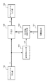
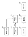
図1に示すように、本実施の形態における署名処理部は、画像発生部101、ドキュメントデータ発生部102、識別情報抽出部103、付加情報埋め込み部104、合成部105、ドキュメントデータ出力部106から構成される。
【0039】
なお、ここで説明する署名処理はソフトウェア処理により実現されても良い。その場合には、上記各部は上記処理に必要な機能を概念的なものとして捉えたものと考慮されるべきものである。
【0040】
まず、画像発生部101の機能について説明する。画像発生部101は、後述するドキュメントデータの背景に設定される画像データI1を発生する。発生した画像データI1は、付加情報埋め込み部104に入力される。
【0041】
以降の説明では、説明を簡単にするために、画像データI1はモノクロの多値画像を表現しているものとするが、本発明はこのような場合には限定されず、フルカラー画像等の任意画像を適用することも可能であることは明らかである。
【0042】
画像発生部101が画像データI1を発生するには、図3におけるROM304,RAM305,HD306,CD308,FD309,DVD310などに予め記憶されている画像データを読み出すことや、モデム313、NIC315などを用いてネットワークを通じて画像データを受信して用いることや、スキャナ319、デジタルカメラ321などを用いて紙に印刷されている原稿をデジタル化して用いることなど種々の手段を用いることが可能であり、入力元は如何なるものでも構わない。画像発生部101において発生した画像データI1は一旦RAM305に保持される。
【0043】
次に、ドキュメントデータ発生部102の機能について説明する。ドキュメントデータ発生部102では、本実施の形態における署名処理部において署名が施されるドキュメントデータDが発生する。発生したドキュメントデータDは、識別情報抽出部103に入力される。
【0044】
以降の説明では、説明を簡単にするために、ドキュメントデータDは文書(白地に黒文字)の2値画像を表現しているものとするが、本発明はこのような場合には限定されず、多値画像やフルカラー画像を適用することも可能であることは明らかである。また、ドキュメントデータDとしてPDFなどの非画像データが発生した場合には、画像データに変換してから処理を行えばよい。
【0045】
ドキュメントデータ発生部102でドキュメントデータを発生させる手段としては、前述した画像発生部101における手段と同様の手段が適用可能である。また、ドキュメントデータとして、テキストデータ(アスキーコードなどによる記述)やアプリケーションに依存したデータ(PDFなど)などが入力された場合には、これらのデータを画像データに変換するためにラスタライズ処理をするようにすれば良い。
【0046】
ドキュメントデータ発生部102において発生したドキュメントデータDは一旦RAM305に保持される。
【0047】
次に、識別情報抽出部103の機能について説明する。識別情報抽出部103では、前記ドキュメントデータ発生部102からRAM305に出力されたドキュメントデータDを読出し、その中から所定の識別情報Inf1を抽出し、抽出された識別情報Inf1を出力する。
【0048】
ここで、識別情報抽出部103で実行される識別情報抽出処理について、図20を用いて詳細に説明する。
【0049】
図20に示すように、本実施の形態における識別情報抽出部103は、識別情報認識領域切り出し部2001、文字認識部2002から構成される。
【0050】
まず、識別情報認識領域切り出し部2001の機能について説明する。識別情報認識領域切り出し部2001には、ドキュメントデータD(文字画像が含まれるデータ)が入力され、ドキュメントデータD中から後段の文字認識処理の対象となる領域の切り出しを行い、切り出された領域データRが出力される。
【0051】
次に、文字認識部2002の機能について説明する。文字認識部2002には、前記識別情報認識領域切り出し部2001において切り出された領域データRを入力し、その領域データRに対し、文字認識処理を実行し、文字認識処理された結果Inf1を出力する。
【0052】
以上説明した識別情報抽出部103は、文字認識すべき領域が一つの場合の処理である。文字認識すべき領域が複数ある場合には、複数回文字認識を行い、更に、対象文字が異なる場合には、それに最適な文字認識手法に切り替えて、識別情報を取り出す。以上説明した処理によって抽出された情報が、識別情報Inf1として出力される。出力された識別情報Inf1は、一旦RAM305に保持される。
【0053】
尚、本実施形態において識別情報抽出部103で実行される処理は、上記識別情報抽出処理に限定されることはなく種々の処理が適用可能である。
【0054】
例えば、ユーザーに対話的に識別情報を選択させる方法として、ドキュメントデータDをモニタ302などに表示し、ユーザーがマウス311やキーボード212を用いてドキュメントデータD中の所望の情報を指定し、指定された位置の情報を抽出することにより識別情報Inf1を抽出可能である。
【0055】
また、ドキュメントデータDが領収書や契約書などの場合、予めフォーマットが定められており、金額や契約者などの被署名データの位置がわかっていることが多い。このような場合に、予め判っている被署名データの位置の情報を領域データRとして用いるようにしても良い。
【0056】
また、以上説明したような領域データRは、後で署名を検証する際に必要となるために、後述する検証処理と共通でなければならない。これは、署名処理部と検証処理部において予め共有しておいたり、署名処理部から検証処理部に対してネットワークを通じて送信したりするようにすればよい。また、ドキュメントデータDが予め定められたフォーマットである場合、このフォーマットを表す情報を送信するようにしても良い。更に、フォーマットを表す情報を前記ドキュメントデータDに可視、或いは不可視の方法で付加しても良い。
【0057】
また、抽出された識別情報Inf1は、識別情報Inf1が容易に悪用されない様に暗号化されても良い。且つ/または、識別情報Inf1は、識別情報Inf1が後述する電子透かしとして埋め込まれた画像データI2に対して、悪意を持った人間により、画像データI2から抽出できない様に内容変更(以下攻撃と呼ぶ)が施された場合にも、正しくその情報を抽出できる様に、誤り訂正符号化が施されても良い。こうして出力された識別情報Inf1は、一旦RAM305に保持される。
【0058】
次に、付加情報埋め込み部104の機能について説明する。前記画像発生部101において発生した画像データI1、及び前記識別情報抽出部103において抽出された識別情報Inf1はRAM305に一旦格納さている。付加情報埋め込み部104は、このRAM305からそれぞれのデータを入力し、入力識別情報Inf1が、付加情報として画像データI1に電子透かしとして埋め込み、その埋め込まれた画像データI2を出力する。電子透かしの埋め込み方法の詳細については後述する。付加情報Inf1が埋め込まれた画像データI2は、一旦RAM305に保持される。
【0059】
次に、合成部105の機能について説明する。合成部105には、前記ドキュメントデータ発生部102において発生したドキュメントデータD、及び前記付加情報埋め込み部104において付加情報Inf1が埋め込まれた画像データI2を、RAM305から入力し、入力されたドキュメントデータDと画像データI2が合成し、合成されたデータI3を出力する。
【0060】
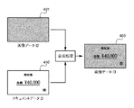
ここで、合成部105において実行される処理の例を図4を用いて説明する。同図において、401は合成部105に入力された画像データI2(付加情報埋め込み後のデータ)、402は合成部105に入力されたドキュメントデータD,403は合成部105において前記画像データ401とドキュメントデータ402が合成された画像データI3である。
【0061】
図4に示すように、画像データI2はドキュメントデータDの背景としてドキュメントデータDの上に重ねられるように合成される。以上のように合成された画像データI3は、一旦RAM305に保持される。
【0062】
次に、ドキュメントデータ出力部106の機能について説明する。ドキュメントデータ出力部106には、前記合成部105において合成された画像データI3をRAM0305から入力し、入力された画像データI3を出力する。
【0063】
ここで、画像データI3を出力する手段としては、図3におけるRAM305,HD306,CD308(CDRやCDRWの場合),FD309,DVD310(DVD−RAMやDVD−R等の場合)などに記録することや、モデム313、NIC315などを用いてネットワークを通じて送信することや、プリンター117などを用いて紙に印刷することなど種々の手段を含む。
【0064】
以上、本実施の形態における署名処理部の動作について説明した。
【0065】
[検証処理部]
次に、図2を用いて本実施の形態に適用される検証処理部(機能)を説明する。
【0066】
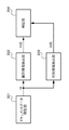
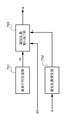
図2に示すように、本実施の形態における検証処理部は、ドキュメントデータ発生部201、識別情報抽出部202、付加情報抽出部203、及び検証部204から構成される。
【0067】
尚、個々で説明する検証処理はソフトウェア処理により実現されても良い。その場合には、上記各部は上記処理に必要な機能を概念的なものとして備えたものとして考慮されるべきものである。説明を簡単なものとするため、検証する側の装置構成も図3に則って説明するが、別装置であっても構わないのは勿論である。
【0068】
まず、ドキュメントデータ発生部201の機能について説明する。ドキュメントデータ発生部201では、検証対象となるドキュメントデータI4が発生する。発生したドキュメントデータI4は識別情報抽出部202に供給される。ここで、ドキュメントデータ発生部201でドキュメントデータI4を発生させる手段としては、前述した図1における画像発生部101における手段と同様の手段を用いることが可能であるので詳細な説明は省略する。尚、ドキュメントデータ発生部201が発生するドキュメントデータI4は、望ましくは図1におけるドキュメントデータ出力部106から出力されたドキュメントデータI3である。或いは、ドキュメントデータI3がコピー機などによりコピーされたものがドキュメントデータI4として入力されてもよい。また、本実施の形態における署名処理部において署名処理されたドキュメントデータではないものが入力されてもよい。本実施の形態における検証処理部の目的は、これらを識別することが可能な方法を提供することである。ドキュメントデータ発生部201において発生したドキュメントデータI4は一旦RAM305に保持される。
【0069】
次に、識別情報抽出部202の機能について説明する。前記ドキュメントデータ発生部201から出力されたドキュメントデータI4はRAM0305に保持されているので、識別情報抽出部202は、そのデータを入力する。そして、入力されたドキュメントデータI4の所定の位置の識別情報を抽出し、抽出された識別情報Inf2を出力する。
【0070】
ここで、識別情報抽出処理の対象となる所定の位置とは、前述した図1における識別情報抽出部103において識別情報が抽出された位置と等しくなければならない。この位置に関する情報は、署名処理部と検証処理部において予め共有しておくことや、署名処理部から検証処理部に対してネットワークを通じて送信することなどによって等しく設定することが可能である。また、ドキュメントデータDが予め決められたフォーマットである場合、このフォーマットを表す情報を前述した署名処理部から受信し、位置に関する情報を決めても良い。更に、ドキュメントデータDに可視、或いは不可視の方法で付加してあるフォーマットを表す情報を抽出して、位置に関する情報を決めても良い。
【0071】
尚、識別情報抽出部202で実行される処理は、図1における識別情報抽出部103で実行される処理と同様であるため詳細な説明は省略する。抽出された識別情報Inf2は、一旦RAM305に保持される。
【0072】
次に、付加情報抽出部203の機能について説明する。付加情報抽出部203は、前記ドキュメントデータ発生部201からRAM305に出力されたドキュメントデータデータI4を入力する。そして、入力されたドキュメントデータI4から電子透かしとして埋め込まれている付加情報Inf3を抽出し、抽出された付加情報Inf3を出力する。電子透かしの抽出方法の詳細については後述する。
【0073】
ここで、抽出した付加情報Inf3が誤り訂正符号化されている場合には誤り訂正復号処理を、また暗号化されている場合には暗号復号処理を実行するようにする。抽出された付加情報Inf3は、一旦RAM305に保持される。
【0074】
次に、検証部204の機能について説明する。検証部204は、前記識別情報抽出部202において抽出された識別情報Inf2、及び前記付加情報抽出手段203において抽出された付加情報Inf3をRAM305から入力し、入力した識別情報Inf2と付加情報Inf3を比較することにより検証処理を行う。
【0075】
ここで、検証処理とは、入力された識別情報Inf2と付加情報Inf3を比較し、両者が等しい場合には「改ざんされていない」と判断し、両者が異なる場合には「改ざんされている」と判断する処理である。また、「改ざんされている」と判断された場合には、識別情報Inf2中のどの位置が異なっているかを通知することも可能である。更に、以上のような検証処理の結果は、改ざんされている識別情報Inf2の位置を示すために、画像データとしてモニタ102上に表示することも可能である。
【0076】
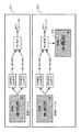
ここで、検証部204において実行される検証処理の一例を図5を用いて説明する。図5において、501は改ざんされていない場合の処理の流れの例、502は改ざんされている場合の処理の流れの例を示している。処理例502中の503は改ざんされている位置を示す画像データの例を示している。
【0077】
501において、識別情報Inf2「¥40,000」と付加情報Inf3「¥40,000」は等しいことから「改ざんされていない」と判断する。一方で、502においては、識別情報Inf2「¥60,000」と付加情報Inf3「¥40,000」は異なることから「改ざんされている」と判断する。更に、「改ざんされている」と判断された場合には、改ざんされている位置を目視しやすい様に、枠を付けたり、網掛けなどの処理を施した画像データを生成し、モニタ302などに表示することにより、ユーザーに改ざんされている位置503を明示することが可能である。
【0078】
以上、本実施の形態における検証処理部について説明した。
【0079】
[電子透かし埋め込み]
以下、図6を用いて本発明に適用される電子透かしの埋め込み処理部(機能)を説明する。
【0080】
まず、以下で説明する電子透かし(デジタルウォーターマーク)とは、“不可視の”電子透かしとも呼ばれ、人間の視覚では殆ど認識できないレベルの変化を、オリジナル画像データIに対して付加させることである。そして、この各変化量の1つ或いはその組み合わせが何らかの付加情報を表している。
【0081】
図6に示すように、本実施形態における埋め込み処理部(付加情報埋め込み部104に相当する)は、画像入力部601、埋め込み情報入力部602、鍵情報入力部603、電子透かし生成部604、電子透かし埋め込み部605、画像出力部606から構成される。
【0082】
なお、ここで説明する埋め込み処理はソフトウェア処理により実現されても良い。その場合には、上記各部は上記処理に必要な機能を概念的なものとして捉えたものと考慮されるべきものである。
【0083】
まず、画像入力部601の機能について説明する。画像入力部601には電子透かしの埋め込み対象となる画像を表す画像データIが入力される。その画像データIは画像入力部601から出力され、電子透かし埋め込み部605に入力される。
【0084】
以降の説明では、説明を簡単にするために、画像データIはモノクロの多値画像を表現しているものとするが、本発明はこのような場合には限定されない。例えばカラー画像データ等の複数の色成分からなる画像データに対して電子透かしを埋め込むならば、その複数の色成分である例えばRGB成分、或いは輝度、色差成分の夫々を上記モノクロの多値画像として扱う様にし、各成分に対して電子透かしを埋め込めばよい。この場合には、モノクロ多値画像へ電子透かしを埋め込む場合と比較して、約3倍のデータ量を埋め込むことが可能となる。
【0085】
次に、埋め込み情報入力部602の機能について説明する。埋め込み情報入力部602には、上記画像データIに電子透かしとして埋め込むべきバイナリデータ列が入力される。そのバイナリデータ列は埋め込み情報入力部602から出力され、電子透かし生成部604に入力される。
【0086】
以下、上記バイナリデータ列を付加情報Infとして説明する。付加情報Infは“0”または“1”の何れかを表すビットの数個の組み合わせによって構成される情報である。
【0087】
なお、上記付加情報Infは、その付加情報Infが容易に悪用されない様に暗号化されていても良い。かつ/または、上記付加情報Infは、この付加情報Infが電子透かしとして埋め込まれた画像データIに対して、悪意を持った人間により、付加情報Infが画像データIから抽出できない様に内容変更(以下攻撃と呼ぶ)が施された場合にも、正しくその付加情報Infを抽出できる様に、誤り訂正符号化が施されても良い。
【0088】
なお上記攻撃には故意によらない攻撃も有る。例えば、一般的な画像処理(非可逆圧縮、輝度補正、幾何変換、フィルタリングなど)が、結果として電子透かしを除去してしまうことも有り、この場合も攻撃であると言える。
【0089】
なお上記暗号化、及び誤り訂正符号化などの処理の詳細は公知であるので、本実施形態でのこれ以上の詳しい説明は省略する。以降では、nビットで表現される付加情報を埋め込む例について詳しく説明する。
【0090】
次に、鍵情報入力部603の機能について説明する。鍵情報入力部603は、付加情報Infの埋め込み、及び抽出に必要な鍵情報kを入力し、それを出力する。鍵情報入力部603から出力された鍵情報kは、電子透かし生成部604に入力される。
【0091】
ここで鍵情報kとはL(正数)ビットで表される実数である。L=8の正数として表現する場合には、例えば“01010101”が鍵情報kの一例であり、正の整数として表現する場合には“85(10進数)”として与えられる。鍵情報kは、後述する擬似乱数発生部702で実行される擬似乱数発生処理に初期値として与えられる。電子透かし埋め込み処理部、及び後述する電子透かし抽出処理部において共通の鍵情報kを使用した場合に限り、電子透かしとして埋め込まれている付加情報Infを正しく抽出することが可能である。即ち、鍵情報kを所有している利用者だけが付加情報Infを正しく抽出することができる。
【0092】
次に、電子透かし生成部604の機能について説明する。電子透かし生成部604は、埋め込み情報入力部602から付加情報Inf、及び鍵情報入力部603から鍵情報kを入力し、入力された付加情報Infと鍵情報kに基づいて電子透かしwが生成し、出力する。
【0093】
電子透かし生成部604の機能の詳細について図7を用いて説明する。図7に示すように、電子透かし生成部604は基本行列生成部701、擬似乱数発生部702、及び擬似乱数割り当て部703から構成される。
【0094】
まずはじめに基本行列生成部701の機能について説明する。基本行列生成部701では、基本行列mが生成される。生成された基本行列mは擬似乱数割り当て部703に供給される。ここで基本行列mとは付加情報Infを構成する各ビットの位置と、前記各ビットが埋め込まれる画像データI上の画素位置を対応付けるために用いられる行列である。
【0095】
ここでは、基本行列生成部701は複数の基本行列を選択的に利用することが可能である。そしてどの基本行列を用いるかは、その時の目的/状況に応じて変化させる必要が有り、本発明ではこれら基本行列の切り替えにより最適な電子透かし(付加情報Inf)の埋めこみが可能である。
【0096】
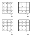
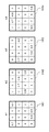
基本行列mの具体例を図8に示す。801は16ビットから構成される付加情報Infを埋め込む場合に用いられる基本行列mの一例を示したものである。801に示す様に16ビットの付加情報Infを埋め込むために、例えば4x4の基本行列mが用いられ、更に1から16の数字が基本行列内の各要素に割り当てられている。
【0097】
図から分かる様に、基本行列m内の要素の値と付加情報Infのビット位置が対応付けられている。具体的には、基本行列内の要素の値が“1”の位置に付加情報Infの最上位ビットを埋め込み、同様に、基本行列内の要素の値が“2”の位置に付加情報Infの最上位ビットの次のビットを埋め込む。以下、順番に各ビットを埋め込む。
【0098】
以下は、上記801からの埋めこみ方法の変形例について説明する。
【0099】
図8の802は8ビットから構成される付加情報Infを埋め込む場合に用いられる基本行列の一例を示したものである。802に示す基本行列は、801に示す基本行列の全要素のうち1から8までの値を持つ要素だけを用いたものである。値を持たない要素の部分には付加情報Infを埋め込まない。上記802の様に付加情報Infを表す各ビットの埋めこみ位置を散らすことにより、801よりも、電子透かし(付加情報Inf)の埋めこみによる画像の変化(画質劣化)を認識しずらくできる。
【0100】
図8の803は802と同様に8ビットから構成される付加情報Infを埋め込む場合に用いられる基本行列mの一例を示したものである。上記802と803は夫々8ビットの付加情報Infを埋め込むことが可能な基本行列mであるが、802は全画素の50%にあたる画素を付加情報Infの埋め込みに用いているのに対して、803は全画素(100%)を付加情報Infの埋め込みに用いている。即ち、1ビット埋め込むために802は基本行列中の1画素を用いているのに対して、803では基本行列中の2画素を用いて付加情報Infの1ビットを埋め込んでいる。上記803の様に、付加情報Infを表す各ビットを埋めこむ回数を増やすことにより、電子透かしが埋め込まれた画像に攻撃が加えられた場合には、801や802よりも、その電子透かし(付加情報Inf)を確実に抽出できる(攻撃耐性が有る)ことになる。
【0101】
ここで、全画素中で電子透かしの埋め込みのために使用する画素の割合を、以降では充填率と呼ぶことにする。前記801を用いた場合充填率は100%、前記802を用いた場合は充填率50%、前記803を用いた場合は充填率100%である。
【0102】
図8の804は、803と同様に全画素を付加情報Infの埋め込みに用いている。即ち、充填率は100%である。しかしながら、803は8ビットの付加情報Infを埋め込むのに対して、804は4ビットの付加情報Infしか埋め込まない。しかし、1ビット埋め込むために803では基本行列中の2画素を用いているのに対して、804では基本行列中の4画素を用いて付加情報Infの1ビットを埋め込んでいる。上記804の様に、付加情報Infを表す各ビットを埋めこむ回数を増やすことにより、電子透かしが埋め込まれた画像に攻撃が加えられた場合には、801や802や803よりも、その電子透かし(付加情報Inf)を確実に抽出できる(攻撃耐性が有る)ことになる。ただし、攻撃耐性が非常に有る代わりに、埋め込む付加情報Infの情報量は4ビットとなり、801や802や803よりも少ない。
【0103】
上述した4つの例を表にまとめると次のようになる。
【0104】
<表1>
----------------------------------------------------------------------
基本行列 充填率 使用画素数/1ビット 埋め込み可能な情報量
----------------------------------------------------------------------
801 100% 1画素 16ビット
802 50% 1画素 8ビット
803 100% 2画素 8ビット
804 100% 4画素 4ビット
----------------------------------------------------------------------
このように、基本行列mをどのような構成にするかによって、充填率と1ビットを埋め込むのに使用する画素数と埋め込み可能な情報量を選択的に設定することができる。上記表1では、充填率は主に電子透かしを埋め込んだ画像の画質に影響するパラメータであり、1ビットを埋め込むために使用する画素数は主に攻撃に対する耐性に影響するパラメータである。充填率を大きくすると電子透かしを埋め込んだ画像の質の劣化は大きくなり、1ビット埋め込むために使用する画素数を多くすると攻撃に対する耐性は強くなる。
【0105】
以上から分かる様に、電子透かしを実現する際には、埋めこみ対象の画質と電子透かしの攻撃に対する耐性と埋め込める付加情報Infの情報量がトレードオフの関係にある。
【0106】
本実施形態においては、上述した複数種類の基本行列mを適応的に選択することによって、電子透かしの耐性と画質と情報量を制御、及び設定することが可能である。
【0107】
以上説明したように生成された基本行列mは擬似乱数割り当て部703に出力される。
【0108】
次に、擬似乱数発生部702の機能について説明する。擬似乱数発生部702では、鍵情報kが入力され、鍵情報kを元に擬似乱数列rが生成される。生成された擬似乱数列rが出力され、擬似乱数割り当て部703に入力される。ここで擬似乱数列rとは、{−1,1}の範囲に含まれる一様分布に従う実数列(複数の実数)である。更に、鍵情報kは擬似乱数を発生させる場合の初期値として用いる。即ち、第1の鍵情報を用いて生成した第1の擬似乱数列と、前記第1の鍵情報とは異なる第2の鍵情報を用いて生成した第2の擬似乱数列は異なる。擬似乱数列rを生成する方法は公知の技術であるので詳細な説明は省略する。生成された擬似乱数列rは擬似乱数割り当て部703に出力される。
【0109】
次に、擬似乱数割り当て部703の機能について説明する。擬似乱数割り当て部703には基本行列mと擬似乱数列rが入力され、擬似乱数列rの各要素が基本行列mの所定の要素に割り当てられる。以降では、基本行列mの所定の要素に乱数列が割り当てられた行列を電子透かしwと呼ぶ。擬似乱数割り当て部703からは生成された電子透かしwが出力される。
【0110】
ここで、擬似乱数列rの各要素を基本行列mの所定の要素に割り当てる処理の詳細について例を用いて説明する。
【0111】
まず、例として図8に示した基本行列804を用いる場合を説明する。前述したように基本行列804を用いることにより4ビットの情報を埋め込み可能である。
【0112】
まずはじめに、基本行列804に示す基本行列内の各要素のうち、値として“1”を持つ要素をラスタースキャン順にスキャンして、順に擬似乱数列rの各要素を割り当てる。割り当てる際には、付加情報Infに応じて付加情報Infのビットが“1”の時は擬似乱数列rの要素をそのまま割り当て、一方で付加情報Infのビットが“0”の時は擬似乱数列rの要素に“−1”をかけた値を割り当てる。
【0113】
次に、値として“2”をもつ要素において同様の処理を実行する。以上の処理を、値としてn(埋め込みビット数)を持つ要素までに対して実行する。以上の示した例によって生成された電子透かしwの一例を図9に示す。同図の901は擬似乱数列rとしてr={0.7,−0.6、−0.9,0.8…}という実数列、付加情報Infとして“1001”という4ビットの情報を用いた場合の例である。
【0114】
詳しく説明すると、次のようになる。ただし、スキャン順は、左端から右端スキャンすることを、1行目、2行目と順に行うものとする。
【0115】
付加情報Infの最上位ビットは“1”であり、対応する乱数の最初の値は0.7である。従って、基本行列804をスキャンした際に最初に検出された“1”の位置には先頭の擬似乱数“0.7”が割り当てられる。そして、次に検出された“1”の位置には、2番目の擬似乱数“−0.6”が割り当てられる。以下、同様に、基本行列の“1”を検出する毎に、対応する順番の擬似乱数を割り当てる。
【0116】
次に、付加情報Infの最上位ビットの次のビット“0”を埋め込む場合には、擬似乱数に対して−1を乗算した値を割振る。すなわち、上記の場合には{−0.7,0.6,0.9,−0.8…}と、符号を反転させた擬似乱数を、基本行列の“2”を検出する毎に割り当てる。
【0117】
以下、付加情報Infの3ビット目、4ビット目についても同様に行うことで、図9の901に示す電子透かしwを得ることができる。
【0118】
こうして生成された電子透かしwは電子透かし生成部604の出力として出力され、電子透かし埋め込み部605に入力される。
【0119】
尚、以上では説明のために16ビット、8ビット及び4ビットの付加情報を埋め込むために4x4の基本行列を用いたが、本実施形態ではこれに限らず、1ビット埋め込むために更に多くの画素を利用し、より大きなサイズの基本行列を用いる場合も本発明の範疇に含む。より大きなサイズの基本行列を用いた場合には、擬似乱数列もより長い実数列を用いることになる。実際には、説明に用いたような4要素から構成される乱数列では、後述する電子透かし抽出処理が正しく動作しない可能性がある。(具体的には、付加情報Infが埋め込まれているにも関わらず、集積画像cと電子透かしw1、w2、…、wnとの相関係数が小さくなる可能性がある。)よって、例えば64ビットの付加情報を埋め込むために充填率50%において256x256の基本行列を用いるような構成とすることも可能である(この場合、1ビット埋め込むために512画素使用することになる)。
【0120】
次に、電子透かし埋め込み部605の機能について説明する。電子透かし埋め込み部605では、画像データI及び電子透かしwが入力され、画像データIに電子透かしwが埋め込まれ、電子透かしwが埋め込まれた画像データI'が出力される。
【0121】
電子透かし埋め込み部605の処理の詳細について説明する。電子透かし埋め込み部605では、
I'i,j=Ii,j+awi,j (式1)
という式に従って、電子透かしの埋め込み処理が実行される。ここで、I'i,jは電子透かしが埋め込まれた画像データ、Ii,jは電子透かしが埋め込まれる前の画像データ、wi,jは電子透かし、i及びjは夫々I、I'及びwのx座標及びy座標を表すパラメータ、aは電子透かしの強度を設定するパラメータである。
【0122】
例えば、aを“10”とすると、埋め込む電子透かしの値は−10乃至+10の範囲となる。aの値を大きく設定することによって耐性の強い電子透かしを埋め込むことが可能であるが、画質劣化が大きくなる。一方で、aの値を小さく設定することによって電子透かしの耐性は弱くなるが、画質劣化は小さくすることが可能である。前述した基本行列mの構成と同様に、aの値を適当に設定することにより(例えば、埋め込む際に、GUI画面等でマウスやキーボードでもってaの値を設定する等)、電子透かしの攻撃に対する耐性と電子透かしを埋め込んだ後の画像の画質のバランスを設定することが可能である。
【0123】
式1に示した電子透かし埋め込み処理の具体例として、4×4の基本行列mを用いた場合の例を図10に示す。図10において1001は式1におけるI'、1002はI、1003はwを表す。図10に示すように、式1の演算は行列内の各要素に対して実行される。
【0124】
以上、式1(図10)に示した演算処理は実際には入力された画像データIの全体に対して繰り返し実行される。例えば、入力された画像データIが24x24画素から構成されている場合には、図11に示す如く4×4画素が縦横とも6×6個備えることになり、各ブロック(4×4画素)に埋め込みが行われる。
【0125】
図11に示すように、入力された画像データIは4×4画素から構成される互いに重ならないブロックに分割され、分割された夫々のブロックに対して式1(図10)に示した演算処理が繰り返し実行される。このように式1(図10)に示した処理が実行されるブロックを、以下マクロブロックと呼ぶ。
【0126】
全てのマクロブロックに対して繰り返し電子透かしの埋め込み処理を実行することにより、結果的に画像全体に電子透かしを埋め込むことが可能である。更に、1つのマクロブロックにはnビットから構成される付加情報Infの全体が埋め込まれている。このことから、少なくともマクロブロックが1つあれば埋め込んだ付加情報Infを抽出することができる。即ち、埋め込んだ付加情報Infを抽出するために画像データIの全体を必要とはせず、画像データIの一部(少なくともひとつのマクロブロック)があれば十分である。
【0127】
このように画像データIの一部から電子透かしを完全に抽出可能であることを「切り取り耐性がある」と呼ぶ。マクロブロック単位の電子透かし埋め込み処理を画像全体に繰り返し実行することにより、電子透かしに切り取り耐性を持たせることが可能である。こうして生成された電子透かし埋め込み済み画像I'は、画像出力部606を通じて、電子透かしの埋め込み処理部の最終的な出力として出力される。
【0128】
[電子透かし抽出処理部]
次に、以上で述べた電子透かしの埋め込み処理部によって埋め込まれた電子透かしを抽出する方法について説明する。以下、図12を用いて本実施形態に適用される電子透かしの抽出処理部(機能)を説明する。
【0129】
図12に示すように、実施形態における抽出処理部は、画像入力部1201、鍵情報入力部1202、抽出パターン生成部1203、電子透かし抽出部1204、電子透かし出力部1205から構成される。
【0130】
なお、ここで説明する抽出処理はソフトウェア処理により実現されても良い。その場合には、上記各部は上記処理に必要な機能を概念的なものとして捉えたものと考慮されるべきものである。
【0131】
まず、画像入力部1201の機能について説明する。画像入力部1201には電子透かしが埋め込まれている可能性がある画像データI''が入力され、その出力は電子透かし抽出部1204に入力される。ここで、画像入力部1201の動作は前述した画像入力部601と同様であるので詳細な動作の説明は省略する。尚、画像入力部1201によって入力される画像データI''は、前述した電子透かしの埋め込み処理部によって電子透かしが埋め込まれた画像データ(I')に限定されることはない。もちろん、電子透かしが埋め込まれた画像データI'であってもよいし、画像データI'が攻撃された画像であっても良い。更に、電子透かしが埋め込まれていない画像データIであっても良い。
【0132】
次に、鍵情報入力部1202の機能について説明する。鍵情報入力部1202において電子透かしを抽出するための鍵情報kが入力され、その出力は抽出パターン生成部1203に入力される。ここで、入力される鍵情報kは、前述した電子透かしの埋め込み処理部における鍵情報入力部603によって入力されたものと同一のものでなければならない。異なる鍵情報が入力された場合には正しく付加情報を抽出することは出来ない。即ち、正しい鍵情報kを有する利用者だけが正しい付加情報Inf'を抽出することが可能である。
【0133】
次に、抽出パターン生成部1203の機能について説明する。抽出パターン生成部1203には鍵情報生成部1202から鍵情報kが入力され、入力された鍵情報kに基づいて抽出パターンが生成され、生成された抽出パターンが出力される。
【0134】
抽出パターン生成部1203の処理の機能の詳細について図13を用いて説明する。図13に示すように、抽出パターン生成部1203は基本行列生成部1301、擬似乱数発生部1302、及び擬似乱数割り当て部1303から構成される。
【0135】
ここで、基本行列生成部1301は前述した基本行列生成部701と、更に擬似乱数発生部1302は擬似乱数発生部702と同じ動作であるので詳細な説明は省略する。但し、基本行列生成部1301において生成される基本行列と基本行列生成部701において生成される基本行列は同一のものでなければ正しく付加情報を抽出することはできない。
【0136】
次に、擬似乱数割り当て部1303の機能の詳細について説明する。擬似乱数割り当て部1303には基本行列mと擬似乱数列rが入力され、擬似乱数列rの各要素が基本行列mの所定の要素に割り当てられる。ここで、前述した埋め込み処理部で用いられた擬似乱数割り当て部703との違いは、擬似乱数割り当て部703においては出力される抽出パターンwは一つであったのに対して、擬似乱数割り当て部1303からは埋め込み情報量の数(本実施形態では、n個)だけ出力されることである。
【0137】
ここで、擬似乱数列rの各要素を基本行列mの所定の要素に割り当てる機能の詳細について例を用いて説明する。例として図8に示した基本行列804を用いる例を説明する。基本行列804を用いた場合、4ビットの付加情報を埋め込み可能であるので、即ち4個の抽出パターンw1、w2、w3、w4が出力される。
【0138】
まずはじめに、基本行列804の各要素のうち、値として“1”を持つ要素をラスタースキャン順にスキャンして、順に擬似乱数列rの各要素を割り当てる。基本行列804の各要素のうち、値として“1”を持つ要素全てに擬似乱数列rの各要素の割り当てが終了したら、擬似乱数列rを割り当てた行列を抽出パターンw1として生成する。図14に抽出パターンの例を示す。抽出パターンw1(1401)は擬似乱数列rとしてr={0.7,−0.6、−0.9,0.8}という実数列を用いた場合の例である。
【0139】
以上の処理を、基本行列804の各要素のうち、値として“2”、“3”、“”,“4”を持つ要素全てに対して実行し、夫々抽出パターンw2(1402)、抽出パターンw3(1403)、抽出パターンw4(1404)として生成する。こうして生成された抽出パターンw1、w2、w3、w4は全てあわせると、電子透かしの埋め込み処理部で用いられた電子透かしwに等しくなる。生成された抽出パターンw1、w2、w3、w4が抽出パターン生成部1203から出力され、電子透かし抽出部1204に入力される。
【0140】
次に、電子透かし抽出部1204の機能について説明する。電子透かし抽出部1204では、画像データI'及び抽出パターンw1、w2、…、wnが入力され、抽出パターンw1、w2、…、wnを用いて画像データI'から付加情報Inf'が抽出され、抽出された付加情報Inf'が出力される。ここで、望ましくは抽出された付加情報Inf'は埋め込んだ付加情報Infに等しい。しかしながら、電子透かしを埋め込んだ画像データI'が種々の攻撃を受けている場合には必ずしも付加情報Infと付加情報Inf'は一致しない。
【0141】
電子透かし抽出部1204の機能の詳細について説明する。電子透かし抽出部1204では、入力された画像データI'から生成された集積画像cと抽出パターンw1、w2、…、wnとの相互相関が夫々計算される。ここで、集積画像cとは、入力された画像データI''をマクロブロックの大きさ(基本行列の大きさ)の互いに重ならないブロックに分割し、分割された夫々のブロックの要素の値の平均値を算出した画像である。
【0142】
集積画像cについて図15に示した具体例を用いて説明する。図15は4×4画素の抽出パターンと24x24画素の画像I''が入力された場合の集積画像cの例である。図15において、1501は24×24画素の画像データI'が4×4画素の互いに重ならないブロックに分割された例を示す。図15に示す例の場合、36個のブロックに分割されている。この36個のブロックの各要素の値の平均値を求めたものが集積画像c(1502)である。
【0143】
こうして生成された集積画像cと抽出パターンw1、w2、…、wnとの相互相関が各々計算される。相関係数を計算する具体的な方法について、集積画像cと抽出パターンwnの相関係数を計算する場合の例を用いて説明する。
【0144】
相関係数は、集積画像cと抽出パターンwnの類似度を測定する統計量であり、
ρ=c'T・w'n/{|c'T|・|w'n|} (式2)
と表される。ここで、c'及びwn'は夫々各要素から、夫々の行列の要素の平均値を引いた値を要素とする行列であり、cTはcの転置行列である。ρは−1から+1の値の範囲の値をとる。集積画像cと抽出パターンwnが正の相関が強い時にρは+1に近づき、一方で集積画像cと抽出パターンwnが負の相関が強い時にρは−1に近づく。ここで「正の相関が強い」とは、「集積画像cが大きいほど抽出パターンwnが大きくなる」という関係のことであり、「負の相関が強い」とは「集積画像cが大きいほど抽出パターンwnが小さくなる」という関係のことである。また、集積画像cと抽出パターンwnが無相関の時には、ρは0となる。
【0145】
こうして算出した相互相関の結果によって、入力された画像データI''に付加情報Inf'が電子透かしとして埋め込まれているか否か、更に、埋め込まれている場合には付加情報Inf'を構成する各ビットが“1”であるか“0”であるかを判定する。
【0146】
集積画像cと抽出パターンw1、w2、…、wnとの相関係数を夫々算出し、算出された相互相関の結果が0に近い場合には「付加情報が埋め込まれていない」、相互相関の結果が0から離れた正数の場合には「ビット1」、相互相関の結果が0から離れた負数の場合には「ビット0」であると夫々判断する。
【0147】
以上説明した相互相関を求めることは、集積画像cと抽出パターンw1、w2、…、wnの夫々が、どれくらい類似しているかを評価することに等しい。即ち、前述した電子透かしの埋め込み処理部によって、画像データI''(集積画像c)の中に抽出パターンw1、w2、…、wnが埋め込まれている場合には、これらは比較的類似しており、この類似の度合いが相互相関値として算出される。更に、ビット“1”が埋め込まれている場合(抽出パターンw1、w2、…、wnが加えられている場合)には相互相関値は正となり、一方で、ビット“0”が埋め込まれている場合(抽出パターンw1、w2、…、wnが減じられている場合)には相互相関値は負になる。
【0148】
具体例として、図16に前述した4ビットの付加情報“1001”が埋め込まれた画像データI''(集積画像c)からw1、w2、w3、w4を用いて電子透かしを抽出する例を示す。
【0149】
まず、集積画像cと4つの抽出パターンw1、w2,w3、w4(4ビットの付加情報Inf'に対応)との相互相関値が夫々算出される。入力された画像データI'(集積画像c)に付加情報Inf'が埋め込まれている場合には、相関係数は夫々“1、−1、−1,1”と算出され、このことから付加情報Inf'は“1001”と判定でき、最終的に4ビットの付加情報Inf'を抽出することが可能である。
【0150】
こうして抽出されたnビットから構成される付加情報Inf'は電子透かし出力部1205を通じて出力される。この際に、前述した電子透かしの埋め込み処理部において、付加情報Infが埋め込まれる時に、誤り訂正符号化処理や暗号化処理が施されている場合には、夫々誤り訂正復号処理や暗号復号処理が実行される。得られた情報が最終的に抽出されたバイナリデータ列(付加情報Inf')として出力される。
【0151】
<第2の実施形態>
上記実施の形態(第1の実施形態)では、検証処理部において処理されるドキュメントデータは、署名処理部から出力された画像データに対して傾いていないような場合を考えた。しかしながら、署名処理部からプリンタ317などを用いてプリントアウトされた原稿が、検証処理部においてスキャナー319などを用いて入力される場合、入力されたドキュメントデータは、署名処理部から出力された画像データに対して傾いている場合が多い。傾いているドキュメントデータを用いて識別情報抽出処理、或いは付加情報抽出処理を実行することは困難であるため、傾きを補正することにより、署名処理部から出力された画像データと同じ状態にする必要がある。そこで、本第2の実施形態は、傾いて入力されたドキュメントデータに対する検証処理について説明する。
【0152】
[検証処理部]
以下、図17を用いて本実施の形態に適用される検証処理部(機能)を説明する。
【0153】
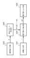
図17に示すように、本実施の形態における検証処理部は、画像発生部1701、傾斜補正部1702、識別情報抽出部1703、付加情報抽出部1704、検証部1705から構成される。
【0154】
ここで、図17に示した検証処理部1702は、図2に示した検証処理部に、傾斜補正部1702が追加された構成である。よって、傾斜補正部1702についてだけ説明をする。画像発生部201と画像発生部1701、識別情報抽出部202と識別情報抽出部1703、付加情報抽出部203と付加情報抽出部1704、検証部204と検証部1705は、夫々同様の処理が実行されるので詳細な説明は省略する。
【0155】
傾斜補正部1702の機能について説明する。傾斜補正部1702には、ドキュメントデータ発生部1701において発生されたドキュメントデータデータI4が、RAM305から入力され、入力されたドキュメントデータI4に対して傾斜補正処理が実行され、傾斜補正処理が施された画像データI5が出力される。
【0156】
ここで、図18、及び図19を用いて傾斜補正処理の一例の詳細な説明をする。
【0157】
図19に示すように、本実施の形態における傾斜補正処理部は、エッジ位置検出部1901、直線決定部1902、回転角度算出部1903、回転処理部1904から構成される。
【0158】
まず、エッジ位置検出部1901の機能について説明する。エッジ位置検出部1901では、ドキュメントデータ発生部1701において発生したドキュメントデータI4が入力され、入力されたドキュメントデータI4中のエッジ位置eが検出され、検出されたエッジ位置eが出力される。
【0159】
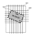
エッジ位置検出処理について図18を用いて説明する。図18において1801は傾斜補正処理部に入力されたドキュメントデータI4、1802はドキュメントデータが含まれている(電子透かしが埋め込まれている)画像領域を示す。ドキュメントデータ1801の夫々4辺から、図18に示す矢印1803のように4辺に垂直な方向に対して、画素値(輝度や濃度)の変化が大きなエッジの位置e(図示の三角印)の検出を行う。
【0160】
次に、直線決定処理部1902の機能について説明する。直線決定処理部1902では、エッジ位置検出処理部1901で検出されたエッジ位置eが入力され、エッジ位置eを用いて4本の直線l(画像データ1802の4辺に相当)が決定され、決定された4本の直線lが出力される。
【0161】
4本の直線lの決定方法の一例として、検出されるエッジ位置eをxy座標における極大・極小位置を元に、4つの区間に区分けし、それぞれの区間でそれぞれ直線を最小2乗近似法を用いて決定する方法や、ハフ変換を用いて決定する方法などが適用可能である。
【0162】
尚、直線から大きく外れる位置のエッジは除外するなどの改良を導入すると直線近似の精度を向上させることが出来る。
【0163】
次に、回転角度算出部1903の機能について説明する。回転角度算出部1903では、直線決定処理部1902で決定された4本の直線lが入力され、入力された4本の直線lを用いて画像データ1802の回転角θを算出し、算出された回転角度θが出力される。
【0164】
回転角度θの算出方法としては、4本の直線lの何れかと画像データ1801の縦または横と成す角度を計算することで、画像データ1801に対する画像データ1802の回転角を算出することができる。一般的には、この方法で回転角θを求めると、θ±90×n(nは整数)の不定性を持つが、本実施の形態において、回転角θは微小な回転角であると仮定すると、回転角θとして比較的小さな角度を選ぶことにより回転角を算出することが可能である。
【0165】
次に、回転処理部1904の機能について説明する。回転処理部1904では、ドキュメントデータI4、及び回転角θが入力され、回転角θだけ画像データI4を回転処理し、更に、回転処理した後、前記検出されたエッジ位置の内部の領域1802だけを切り取り、切り取られた領域が画像データI5として出力される。
【0166】
以上、本実施の形態における傾斜補正処理の一例を説明した。尚、本発明はこれに限定されることなく、種々の傾斜補正処理を用いることが可能である。
【0167】
こうして傾斜補正処理が施された画像データI5が識別情報抽出部1703、及び付加情報抽出部1704に入力されることによって、正しく識別情報抽出処理、及び付加情報抽出処理を実行することが可能である。即ち、本実施の形態における検証処理部を用いることにより、検証処理部に入力されたドキュメントデータが傾いている場合でも、正しく検証処理を実行することが可能である。
【0168】
また、一般に、スキャナに原稿をセットする際、ユーザは原稿をランドスケープ、ポートレートのいずれかで読み取らせようとして原稿をセットする。従って、場合によっては、上記傾斜補正を行ったとしても、90°ずれている場合もあり得る。従って、上記補正を行った場合であっても、付加情報の抽出が失敗したとしても、入力した画像を90°回転させて再度抽出する処理を行うことが望ましい。
【0169】
<第3の実施形態>
上記実施の形態(第1の実施形態、及び第2の実施形態)では、署名処理部において生成された画像データI3中の文字データ部分に改竄が施された場合に、検証処理部において、文字データが改竄されたこと、更に、改竄された場合には、改竄された文字データ部分を特定可能な方式を説明した。この方式では、署名処理部において電子透かしとして埋め込まれた識別情報Inf1は、検証処理部において正しく付加情報Inf3として抽出されるが、一方で検証処理部において識別情報Inf2が正しく識別されなかった場合をも想定している。
【0170】
これは、付加情報Inf3が検証処理部において正しく(識別情報Inf1と等しい値として)抽出可能であることを前提としている。しかしながら、万一、攻撃や画質劣化などの原因で、付加情報Inf3が検証処理部において正しく抽出できなかった場合には、検証処理部において識別情報Inf2と付加情報Inf3は一致しないことから、「何らかの攻撃がされている」という判定は可能である。しかしながら、例えば、画質劣化により付加情報Inf3が抽出できず、更に文字データ部分は全く改竄されていない場合(識別情報Inf2が正しく抽出された場合)にも「何らかの攻撃がされている」と判定されてしまう。よって、付加情報Inf3は攻撃や画質劣化に対してできるだけ耐性が強く、検証処理部において正しく抽出できるようにすることが望ましい。
【0171】
一般的に、攻撃に対して耐性を強くするためには、電子透かしを強く埋め込むようにすれば良い。このために、例えば、前述した式1においてaの値を大きくするようにする。しかしながら、単純に電子透かしを強く埋め込むだけでは、画質劣化が大きくなり望ましくない場合がある。
【0172】
そこで、本実施の形態においては、出来るだけ人間の目に見えにくいように、且つ、強い電子透かしとして付加情報Inf3を埋め込む方法を説明する。
【0173】
以下、図21を用いて本実施の形態に適用される署名処理部(機能)を説明する。なお、以下の説明では、ホストコンピュータ301に電源が投入され、OSがRAM305にロードされ、しかる後に、本実施形態で説明する処理を行うアプリケーションがRAM305にロードされている場合である。従って、各処理部は、該当するプログラム及びそれを実行するCPU303、場合によっては周辺のハードウェアでもって実現することになる。
【0174】
図21に示すように、本実施の形態における署名処理部は、画像発生部211、ドキュメントデータ発生部212、識別情報抽出部213、付加情報埋め込み部214、合成部215、ドキュメントデータ出力部216、及び特徴情報抽出部217から構成される。
【0175】
尚、ここで説明する署名処理はソフトウェア処理により実現されても良い。その場合には、上記各部は上記処理に必要な機能を概念的なものとして捉えたものと考慮されるべきものである。
【0176】
ここで、画像発生部211、ドキュメントデータ発生部212、識別情報抽出部213、付加情報埋め込み部214、合成部215、ドキュメントデータ出力部216は、夫々、図1における、画像発生部101、ドキュメントデータ発生部102、識別情報抽出部103、合成部105、ドキュメントデータ出力部106と同様の機能であるので詳細な説明は省略する。以降では、機能の異なる特徴情報抽出部217、及び付加情報埋め込み部214の機能について説明する。
【0177】
まず、特徴情報抽出部217の機能について説明する。特徴情報抽出部217は、ドキュメントデータ発生部212において発生したドキュメントデータDが入力され、入力されたドキュメントデータD中の特徴情報Cが抽出され、抽出された特徴情報Cが出力される。
【0178】
本実施の形態における特徴情報Cとは、後述する付加情報埋め込み部214において、電子透かしを強く埋め込む箇所である。特徴情報Cについて図22に具体例を示して説明する。
【0179】
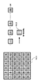
図22において、221は入力されたドキュメントデータDである。222は221に示すドキュメントデータ中の文字データ部分を全て含むような特徴情報Cである。また、223は221に示すドキュメントデータ中の印鑑などの重要な部分だけを含むような特徴情報Cである。更に、224は221に示すドキュメントデータ中の金額などの改竄されないようにすべき部分だけを含むような特徴情報Cである。
【0180】
本実施形態においては、図22に示すように、ドキュメントデータDを互いに重ならない複数の矩形領域に分割し、矩形領域毎に特徴情報か否かを判定し、特徴情報である領域を(図中、黒色領域として示した矩形領域)後段の付加情報埋め込み部214に電子透かしを強く埋め込む領域として出力する。
【0181】
尚、本実施形態では説明の為に、特徴情報を矩形領域として示したが本発明はこれに限定されることなく特徴情報Cとして任意の形状を指定可能であることは明らかである。
【0182】
また、本実施形態では特に特徴領域として重要な部分を抽出するような説明をしたが、本発明はこれに限定されることなく、種々の領域を特徴領域として抽出可能であることは明らかである。特徴情報抽出部217において抽出された特徴情報Cには、後述するように強い電子透かしが埋め込まれるために画質劣化が大きくなる場合がある。特徴情報Cとしてドキュメントデータ中の重要な部分を抽出するようにした場合に、当該重要な部分の背景の画質劣化が大きくなってしまい問題となる場合がある。よって、重要な部分の画質劣化を小さくするために、重要な部分を避け、重要な部分の周囲の領域を特徴情報Cとして抽出するようにしても良い。
【0183】
以上、説明したような特徴情報Cはユーザにより手動で指定するようにしても良いし、或いは自動的に抽出するようにしても良い。ユーザにより手動で指定する場合には、ドキュメントデータDをモニタ302などに表示し表示されたモニタ上のドキュメントデータDをマウス311などを用いて指定するようにすればよい。また、自動的に抽出する場合には、ドキュメントデータDに二値化処理を施し、黒色画素を多く含む領域を特徴情報Cとして指定したりすればよい。しかしながら、本発明はこれに限定されることなく、様々な特徴情報抽出処理を用いることが可能である。
【0184】
以上、本実施形態における特徴情報Cについて説明した。抽出された特徴情報Cは付加情報埋め込み部214に入力される。
【0185】
次に、付加情報埋め込み部214の機能について説明する。付加情報埋め込み部214は、画像データI1、識別情報Inf1、及び特徴情報Cが入力され、特徴情報Cを用いて識別情報Inf1が電子透かしとして画像データI1に埋め込まれ、電子透かしが埋め込まれた画像データI2が出力される。
【0186】
本実施形態における付加情報埋め込み処理は、前段の特徴情報抽出部217で抽出された特徴情報Cに示された領域について、それ以外の領域に比べて強く電子透かしを埋め込むように、矩形領域毎に処理する。例えば、特徴情報の領域(図22における黒色領域)では式1におけるaを“20”とし、特徴情報以外の領域(図22における白色領域)では式1におけるaを“10”として、付加情報埋め込み処理を実行する。
【0187】
しかしながら、本発明はこれに限定されることなく、種々の方法で電子透かしの強度を変化させて、領域毎に異なる強度で電子透かしを埋め込むことを含む。
【0188】
以上のように電子透かしを埋め込むことによって、画像全体の画質を劣化させることなく電子透かしを強く埋め込むことが可能である。また、ドキュメントデータD中で印鑑や文字データ部分などの重要な領域は攻撃される可能性が高いことから、特徴情報Cとしてこれらの領域を設定することにより、電子透かしの耐性をより強くすることが可能となる。
【0189】
<第4の実施形態>
上記実施の形態(第1の実施形態、第2の実施形態、及び第3の実施形態)では、図20に示すように、識別情報認識領域切り出し部2001において領域データRを抽出し、文字認識部2002において抽出された領域R内の文字を認識し、認識された文字データInf1を背景データに埋め込むようにしていた。
【0190】
この場合、前述したように署名処理部と検証処理部とで領域データRを共通に設定する必要がある。しかしながら、本発明はこれに限定されることなく、領域データRを必要としないようにすることも可能である。
【0191】
以下、図23を用いて本実施形態に適応される識別情報抽出部103(及び202)を説明する。
【0192】
図23に示すように、本実施形態における識別情報抽出部は、文字認識部231、及び特定文字選択部から構成される。
【0193】
まず、文字認識部231の機能について説明する。文字認識部231は、ドキュメントデータDを入力し、入力されたドキュメントデータに含まれる全ての文字を認識し、認識された全ての文字を文字列Cとして出力する。文字認識部231における処理は、図20における文字認識部2002と同様であるので詳細な説明は省略する。
【0194】
次に、特定文字選択部232の機能について説明する。特定文字選択部232は、前段の文字認識部231で認識された全ての文字列Cを入力し、文字列Cの中から特定の文字を選択し、選択された全ての文字を文字列Inf1として出力する。
【0195】
特定文字選択部232では、入力された文字列Cの中から予め決められた所定の文字に一致する文字列が選択する。例えば、領収書などの金額情報を被署名データとする場合には、「0」から「9」の数字や「¥」や「$」などの記号を選択するするようにすればよい。
【0196】
或いは、入力された文字列Cの中から予め決められた所定の文字に一致する文字列を抽出し、その後に続く所定数の文字列を選択するようにしても良い。例えば、契約書などの契約番号を被署名データとする場合には、「契約番号」という文字列を抽出し、抽出された文字列の後に続く数桁の文字列を選択するようにすれば良い。
【0197】
以上、本実施形態に適応可能な識別情報抽出部の動作を説明した。本実施形態によれば、文字認識部231においてドキュメントデータDの全領域を文字認識処理の対象とし、且つ、特定文字選択部232において署名処理部と検証処理部で共通の文字を選択するようにすることによって、署名処理部と検証処理において領域データRを共有する必要がないようにできる。
【0198】
<適用例の説明>
以上説明した実施形態での適用例としては様々なものが考えられる。ここでは、パーソナルコンピュータ上で動作するプリンタドライバに適用させた例を説明する。
【0199】
通常、プリンタドライバは、ワープロアプリケーションから印刷させる対象のデータを受信し、それを出力対象のプリンタが解釈できる記述にして出力する。従って、アプリケーション上で印刷を指示した際に、先ず、背景となる画像を予め登録していた複数の中から選択させ、印刷の指示を行う。
【0200】
文章を印刷させる場合には、文字コードを含むデータがプリンタドライバに渡されるので、その中の文字列を抽出することで、埋め込むべき付加情報を抽出できる。すなわち、この場合には、先に説明した文字認識は不要となる。アプリケーションから指定された背景画像にその付加情報を埋め込む。そして、埋め込み結果と印刷させようとするデータとを合成したデータをプリンタに適用するデータに変換し、OSを介して出力すれば良いであろう。
【0201】
以上説明したように、本実施形態によれば、ドキュメントの背景に前記ドキュメントの内容を電子透かしとして埋め込むことによって、前記電子透かしが埋め込まれたドキュメントが改ざんされているか否かを検証可能であり、且つ、改ざんされていると判断された場合には改ざんされている位置を特定することが可能である。
【0202】
なお、実施形態で説明した付加情報の埋め込み及びその抽出方法はその一例であって、他の手法を用いても良く、上記実施形態によって本発明が限定されるものではない。
【0203】
また、上記実施形態での説明から明らかなように、本発明の主要部分はパーソナルコンピュータ上で動作するアプリケーションとして提供できるものである。従って、本発明はコンピュータプログラムをもその範疇とするものである。更に、通常、コンピュータプログラムはフロッピー(R)ディスクやCDROM等を可搬性のコンピュータ可読記憶媒体に格納されており、その媒体をコンピュータにセットしてコピー或いはインストールすることで実行可能となるわけであるから、コンピュータ可読記憶媒体も本発明の範疇に含まれることも明らかである。
【0204】
【発明の効果】
以上説明したように本発明によれば、ドキュメントの背景に前記ドキュメントの内容を電子透かしとして埋め込むことによって、前記電子透かしが埋め込まれたドキュメントが改ざんされているか否かを検証可能であり、且つ、改ざんされていると判断された場合には改ざんされている位置を特定することが可能である。
【図面の簡単な説明】
【図1】第1の実施の形態における署名処理部の構成を示す図である。
【図2】第1の実施の形態における検証処理部の構成を示す図である。
【図3】本実施形態に適用可能な情報処理装置の構成を示す図である。
【図4】本実施形態における合成処理部の説明をする図である。
【図5】本実施形態における検証処理部の説明をする図である。
【図6】本実施形態における電子透かしの埋め込み処理を説明するブロック図である。
【図7】本実施形態における電子透かし生成部を説明するブロック図である。
【図8】本実施形態における基本行列の一例を示す図である。
【図9】本実施形態における電子透かしの一例を示す図である。
【図10】本実施形態における電子透かし埋め込み演算の例を示す図である。
【図11】本実施形態におけるマクロブロックを示す図である。
【図12】本実施形態における電子透かしの抽出処理を説明するブロック図である。
【図13】本実施形態における抽出パターン生成部の一例を示す図である。
【図14】本実施形態における抽出パターンの一例を示す図である。
【図15】本実施形態における集積画像を用いた電子透かしの抽出の例を説明する図である。
【図16】本実施形態における集積画像を用いた電子透かしの抽出演算の例を説明する図である。
【図17】第2の実施の形態における検証処理部の構成を示す図である。
【図18】第2の実施の形態における傾斜補正を説明する図である。
【図19】第2の実施の形態における傾斜補正部の構成を示す図である。
【図20】本実施形態における識別情報抽出部の構成を示す図である。
【図21】第3の実施形態における署名処理部の構成を示す図である。
【図22】第3の実施形態における特徴情報を説明する図である。
【図23】第4の実施形態における識別情報抽出部を説明する図である。[0001]
BACKGROUND OF THE INVENTION
The present invention relates to a method and apparatus for verifying whether document data has been tampered with, a computer program, and a computer-readable storage medium.
[0002]
[Prior art]
In recent years, various information such as character data, image data, and voice data has been digitized due to the rapid development and spread of computers and their networks. Along with the digitization of such information, various documents that conventionally used paper or the like are often handled as digital data. However, digital data can be easily falsified, and prevention of falsification of digital data is a major problem. For this reason, security techniques for preventing tampering are rapidly gaining importance. Therefore, a method and a system have been proposed that detect when digital data has been falsified or counterfeited.
[0003]
For example, a system using a digital signature is well known as a system for detecting the falsification and forgery. Here, the digital signature will be briefly described.
[0004]
The digital signature means that the sender sends signature data corresponding to the data together with the data, and the receiver verifies the signature data to confirm the validity of the data. Confirmation of the validity of data using a hash function and public key cryptography for digital signature data generation is as follows.
[0005]
When the secret key is Ks and the public key is Kp, the sender performs an operation for compressing the plaintext data M by a hash function and calculating an output h (for example, 128 bits) of a certain length. Next, an operation for converting the h with the secret key Ks to create the digital signature data s, that is, D (Ks, h) = s is performed. Thereafter, the digital signature data s and the plaintext data M are transmitted.
[0006]
Meanwhile, the receiver converts the received digital signature data s with the public key Kp, that is, E (Kp, s) = E (Kp, D (Ks, h ″)) = h ″ and the received plaintext data. An operation for calculating h ′ by compressing M ′ using the same hash function as that of the sender is performed. If h ′ and h ″ match, it is determined that the received data M ′ is valid.
[0007]
When the plaintext data M is tampered between transmission and reception, E (Kp, s) = E (Kp, D (Ks, h ″)) = hh ″, and the received plaintext data M ′ is the same as the sender Since h ′ compressed by the hash function does not match, tampering can be detected.
[0008]
Here, if the digital signature data s is also tampered with the plaintext data M, tampering cannot be detected. However, this requires obtaining plaintext data M from h, and such a calculation is impossible due to the one-way nature of the hash function. As described above, it is possible to correctly authenticate data by using a digital signature using a public key cryptosystem and a hash function.
[0009]
Next, the hash function will be described. The hash function is used for speeding up the generation of the digital signature. The hash function has a function of processing plaintext data M having an arbitrary length and outputting an output h having a fixed length. Here, the output h is called a hash value (or message digest, digital fingerprint) of the plaintext data M. As a property required for the hash function, unidirectionality and collision resistance are required. Unidirectionality means that when h is given, it is difficult to calculate plaintext data M such that h = H (M). Collision resistance means that when plaintext data M is given, calculation of plaintext data M ′ (M ≠ M ′) where H (M) = H (M ′) is difficult in terms of computational complexity, and H ( It is difficult to calculate plaintext data M and M ′ in which M) = H (M ′) and M ≠ M ′.
[0010]
As hash functions, MD-2, MD-4, MD-5, SHA-1, RIPEMD-128, RIPEMD-160, and the like are known, and these algorithms are open to the public.
[0011]
Next, public key cryptography will be described. Public key cryptography is an encryption method in which an encryption key and a decryption key are different and the encryption key is disclosed and the decryption key is kept secret. As a feature of public key cryptography,
(A) Since the encryption key and the decryption key are different and the encryption key can be disclosed, it is not necessary to secretly distribute the encryption key, and key distribution is easy.
(B) Since each user's encryption key is made public, the user only has to store his / her decryption key in a secret manner.
(C) It is possible to realize an authentication function for the receiver to confirm that the sender of the sent message is not a fake and that the message has not been tampered with. Is mentioned.
[0012]
For example, for plaintext data M, if the encryption operation using the public encryption key Kp is E (Kp, M) and the decryption operation using the secret decryption key Ks is D (Ks, M), The key encryption algorithm first satisfies the following two conditions. (1) When Kp is given, the calculation of E (Kp, M) is easy. Given Ks, the calculation of D (Ks, M) is easy. (2) If Ks is not known, even if Kp and E are calculated and C = E (Kp, M) is known, it is difficult to determine M in terms of computational complexity.
[0013]
Next, in addition to the above (1) and (2), the following condition (3) is satisfied, whereby the secret communication can be realized. (3) E (Kp, M) can be defined for all plaintext data M, and D (Ks, E (Kp, M)) = M holds. In other words, since Kp is open to the public, anyone can calculate E (Kp, M), but it is a secret that M can be obtained by calculating D (Ks, E (Kp, M)). Only the person who has the key Ks.
[0014]
On the other hand, in addition to the above (1) and (2), authentication communication can be realized by satisfying the following condition (4). (4) D (Ks, M) can be defined for all plaintext data M, and E (Kp, D (Ks, M)) = M holds. That is, only the person who has the secret key Ks can calculate D (Ks, M), and another person calculates D (Ks ', M) using the fake secret key Ks' and calculates Ks. Even if pretending to be the owner, E (Kp, D (Ks ′, M)) ≠ M because the receiver can confirm that the received information is illegal. Further, even if D (Ks, M) is tampered with, E (Kp, D (Ks, M) ′) ≠ M, and the receiver can confirm that the received information is illegal.
[0015]
RSA cipher, R cipher, W cipher, and the like are known as representative examples that can perform the above-described secret communication and authentication communication.
[0016]
Here, encryption and decryption of the RSA encryption that is currently most used is expressed by the following equations.
Encryption: Encryption key (e, n) Encryption conversion C = Me (mod n)
Decryption: Decryption key (d, n) Decryption transformation M = Cd (mod n)
n = p · q where p and q are large different prime numbers.
[0017]
As described above, the RSA cipher requires a power operation and a remainder operation for both encryption and decryption, so that the amount of computation is enormous compared to common key cryptography such as DES, and high-speed processing is difficult.
[0018]
As described above, falsification and counterfeit detection in the prior art is a method that requires the digital signature in addition to digital data. Usually, a digital signature is transmitted by a method attached to a header portion of digital data or the like. However, the digital signature attached due to digital data format conversion or the like may be easily removed. If the digital signature is removed, the digital data cannot be authenticated.
[0019]
A method for solving this problem is disclosed in
[0020]
[Patent Document 1]
JP-A-10-164549
[0021]
[Problems to be solved by the invention]
As described above, in order to authenticate digital data, it is important that authentication information such as a digital signature is inseparable from digital information. When the data to be signed is image data, it is possible to apply the method of
[0022]
The present invention has been made in view of such problems, and an object thereof is to provide an information processing method and apparatus, a computer program, and a computer-readable storage medium that can verify falsification of document data such as a document.
[0023]
[Means for Solving the Problems]
In order to solve this problem, for example, an information processing method of the present invention has the following configuration. That is,
An information processing method for embedding additional information in a document,
Including text string by document data input meansEnter document dataDocument data inputInput process;
The extraction means recognizes characters in the input document data and uniquely identifies the input document data based on the recognition result.An extraction step of extracting identification information as additional information;
A determination step of determining a region position where the character string is located in the input document data by the determination unit, and generating position information representing the determined region position;
By the image input means,A given imageAs background image datainputImage inputProcess,
The embedding means embeds the identification information extracted in the extraction step in a region outside the region indicated by the position information in the background image data using a first parameter that defines the strength of the digital watermark, The identification information extracted in the extraction step is used in a corresponding area in the background image data indicated by the position information, using a second parameter indicating a higher intensity than the first parameter.EmbedembeddedProcess,
By means of synthesisAfter embedding by the embedding processbackground imageData and entered in the document data input processDocument dataAndA synthesis step to synthesize;
An output step of outputting the document data after the synthesis by the synthesis step by an output means;Is provided.
[0024]
Another invention has the following configuration. That is,
An information processing method for verifying whether document data has been tampered with,
An input process for inputting document data;
An identification information extracting step for recognizing identification information in the input document data;
An additional information extraction step of extracting additional information added to the background of the document data;
The identification information extracted in the identification information extraction step and a comparison step for comparing the additional information extracted in the additional information extraction step.
[0025]
Another invention has the following configuration. That is,
An information processing method for embedding additional information in document data,
Inputting document data;
Inputting a predetermined image;
A feature region extraction step of extracting a feature region from the document data;
An embedding step of embedding additional information in the image data with different intensities according to the feature region;
And a synthesis step of synthesizing the embedded image as a background image of the document data.
[0026]
[Embodiments of the Invention]
Hereinafter, embodiments according to the present invention will be described in detail with reference to the accompanying drawings.
[0027]
FIG. 3 shows the overall configuration of an information processing apparatus applicable to this embodiment. In the figure, a
[0028]
Inside the
[0029]
In the figure,
[0030]
A
[0031]
[0032]
[0033]
[0034]
[0035]
[0036]
[0037]
[Signature Processing Department]
Hereinafter, the signature processing unit (function) applied to the present embodiment will be described with reference to FIG. In the following description, the
[0038]
As shown in FIG. 1, the signature processing unit in the present embodiment includes an
[0039]
The signature processing described here may be realized by software processing. In that case, each of the above sections should be considered as a conceptual view of the functions necessary for the above processing.
[0040]
First, the function of the
[0041]
In the following description, in order to simplify the description, it is assumed that the image data I1 represents a monochrome multi-valued image. However, the present invention is not limited to such a case, and an arbitrary image such as a full-color image is used. Obviously, it is also possible to apply an image.
[0042]
In order for the
[0043]
Next, the function of the document
[0044]
In the following description, in order to simplify the description, it is assumed that the document data D represents a binary image of a document (black characters on a white background), but the present invention is not limited to such a case, It is obvious that a multi-value image or a full color image can be applied. When non-image data such as PDF is generated as the document data D, the processing may be performed after conversion to image data.
[0045]
As means for generating document data in the document
[0046]
Document data D generated in the document
[0047]
Next, the function of the identification
[0048]
Here, the identification information extraction process executed by the identification
[0049]
As shown in FIG. 20, the identification
[0050]
First, the function of the identification information recognition
[0051]
Next, functions of the
[0052]
The identification
[0053]
Note that the process executed by the identification
[0054]
For example, as a method for allowing the user to select identification information interactively, the document data D is displayed on the
[0055]
In addition, when the document data D is a receipt or a contract, the format is determined in advance, and the position of the signed data such as the amount and the contractor is often known. In such a case, information on the position of the signed data that is known in advance may be used as the area data R.
[0056]
Further, since the area data R as described above is necessary when verifying the signature later, it must be common to the verification process described later. This may be shared in advance between the signature processing unit and the verification processing unit, or may be transmitted from the signature processing unit to the verification processing unit via the network. If the document data D has a predetermined format, information representing this format may be transmitted. Further, information indicating the format may be added to the document data D by a visible or invisible method.
[0057]
Further, the extracted identification information Inf1 may be encrypted so that the identification information Inf1 is not easily abused. And / or the content of the identification information Inf1 is changed so that it cannot be extracted from the image data I2 by a malicious person with respect to the image data I2 embedded as a digital watermark described later (hereinafter referred to as an attack). ), Error correction coding may be performed so that the information can be correctly extracted. The identification information Inf1 output in this way is temporarily held in the
[0058]
Next, the function of the additional
[0059]
Next, the function of the
[0060]
Here, an example of processing executed in the
[0061]
As shown in FIG. 4, the image data I2 is synthesized so as to be superimposed on the document data D as the background of the document data D. The image data I3 synthesized as described above is temporarily held in the
[0062]
Next, functions of the document
[0063]
Here, as means for outputting the image data I3, recording on the
[0064]
The operation of the signature processing unit in the present embodiment has been described above.
[0065]
[Verification processing section]
Next, a verification processing unit (function) applied to the present embodiment will be described with reference to FIG.
[0066]
As shown in FIG. 2, the verification processing unit in the present embodiment includes a document
[0067]
The verification process described individually may be realized by software processing. In that case, each of the above-mentioned units should be considered as having a function necessary for the above processing as a conceptual one. In order to simplify the description, the apparatus configuration on the verification side will be described with reference to FIG. 3, but it is needless to say that another apparatus may be used.
[0068]
First, the function of the document
[0069]
Next, the function of the identification
[0070]
Here, the predetermined position that is the target of the identification information extraction process must be equal to the position from which the identification information is extracted by the identification
[0071]
The processing executed by the identification
[0072]
Next, the function of the additional
[0073]
Here, when the extracted additional information Inf3 is subjected to error correction coding, error correction decoding processing is executed, and when it is encrypted, encryption decoding processing is executed. The extracted additional information Inf3 is temporarily held in the
[0074]
Next, the function of the
[0075]
Here, the verification process compares the input identification information Inf2 and the additional information Inf3, and determines that the two are the same and determines that the information has not been falsified. It is a process to judge. Further, when it is determined that “tampered”, it is possible to notify which position in the identification information Inf2 is different. Furthermore, the result of the verification process as described above can be displayed on the
[0076]
Here, an example of the verification process executed in the
[0077]
In 501, since the identification information Inf 2 “¥ 40,000” and the additional information Inf 3 “¥ 40,000” are equal, it is determined that the information has not been tampered with. On the other hand, in 502, since the identification information Inf2 “¥ 60,000” and the additional information Inf3 “¥ 40,000” are different, it is determined that they are “tampered”. Further, if it is determined that the image has been tampered with, image data that has been subjected to processing such as a frame or shading is generated so that the tampered position can be easily seen, and the
[0078]
The verification processing unit in the present embodiment has been described above.
[0079]
[Digital watermark embedding]
The digital watermark embedding processing unit (function) applied to the present invention will be described below with reference to FIG.
[0080]
First, the digital watermark (digital watermark) described below is also referred to as “invisible” digital watermark, and is to add a change of a level hardly recognizable by human vision to the original image data I. . One or a combination of the amounts of change represents some additional information.
[0081]
As shown in FIG. 6, the embedding processing unit (corresponding to the additional information embedding unit 104) in this embodiment includes an
[0082]
The embedding process described here may be realized by software processing. In that case, each of the above sections should be considered as a conceptual view of the functions necessary for the above processing.
[0083]
First, the function of the
[0084]
In the following description, for the sake of simplicity, it is assumed that the image data I represents a monochrome multi-valued image, but the present invention is not limited to such a case. For example, if an electronic watermark is embedded in image data composed of a plurality of color components such as color image data, the plurality of color components, for example, RGB components, or luminance and color difference components, respectively, are converted into the monochrome multi-valued image. It is only necessary to embed a digital watermark for each component. In this case, it is possible to embed approximately three times the amount of data as compared to embedding a digital watermark in a monochrome multi-valued image.
[0085]
Next, the function of the embedded
[0086]
Hereinafter, the binary data string will be described as additional information Inf. The additional information Inf is information composed of several combinations of bits representing either “0” or “1”.
[0087]
The additional information Inf may be encrypted so that the additional information Inf is not easily abused. And / or the content of the additional information Inf is changed so that the additional information Inf cannot be extracted from the image data I by a malicious person with respect to the image data I in which the additional information Inf is embedded as a digital watermark ( Even when an attack is performed), error correction coding may be performed so that the additional information Inf can be correctly extracted.
[0088]
In addition, there is an unintentional attack in the above attack. For example, general image processing (irreversible compression, luminance correction, geometric transformation, filtering, etc.) may result in removal of the digital watermark, which is also an attack in this case.
[0089]
Note that details of the processing such as the encryption and error correction coding are well known, and thus further detailed description in this embodiment will be omitted. Hereinafter, an example in which additional information expressed by n bits is embedded will be described in detail.
[0090]
Next, the function of the key
[0091]
Here, the key information k is a real number represented by L (positive number) bits. When expressed as a positive number with L = 8, for example, “01010101” is an example of the key information k, and when expressed as a positive integer, it is given as “85 (decimal number)”. The key information k is given as an initial value to a pseudo random number generation process executed by a pseudo random
[0092]
Next, the function of the digital
[0093]
Details of the function of the digital
[0094]
First, the function of the basic
[0095]
Here, the basic
[0096]
A specific example of the basic matrix m is shown in FIG.
[0097]
As can be seen from the figure, the element values in the basic matrix m are associated with the bit positions of the additional information Inf. Specifically, the most significant bit of the additional information Inf is embedded at a position where the element value in the basic matrix is “1”, and similarly, the additional information Inf is stored at a position where the element value in the basic matrix is “2”. Embed the next bit after the most significant bit. Hereinafter, each bit is embedded in order.
[0098]
In the following, a modification of the embedding method from 801 will be described.
[0099]
802 in FIG. 8 shows an example of a basic matrix used when embedding additional information Inf composed of 8 bits. The basic matrix shown in 802 uses only elements having values from 1 to 8 among all the elements of the basic matrix shown in 801. The additional information Inf is not embedded in the part of the element having no value. By dispersing the embedding positions of the respective bits representing the additional information Inf as in the above-described 802, it is possible to make it more difficult to recognize the image change (degradation of image quality) due to the embedding of the digital watermark (additional information Inf) than the 801.
[0100]
803 in FIG. 8 shows an example of a basic matrix m used when embedding additional information Inf composed of 8 bits, like 802. 802 and 803 are basic matrices m that can embed 8-bit additional information Inf, respectively, whereas 802 uses pixels corresponding to 50% of all pixels for embedding additional information Inf, whereas 803 Uses all pixels (100%) for embedding the additional information Inf. That is, in order to embed 1 bit, 802 uses one pixel in the basic matrix, whereas 803 uses 2 pixels in the basic matrix to embed 1 bit of the additional information Inf. When an attack is applied to an image in which a digital watermark is embedded by increasing the number of times of embedding each bit representing the additional information Inf as in 803 above, the digital watermark (additional) is applied rather than 801 and 802. Information Inf) can be reliably extracted (has attack resistance).
[0101]
Here, the ratio of the pixels used for embedding the digital watermark among all the pixels is hereinafter referred to as a filling rate. When 801 is used, the filling factor is 100%, when 802 is used, the filling factor is 50%, and when 803 is used, the filling factor is 100%.
[0102]
804 in FIG. 8 uses all pixels for embedding the additional information Inf, as in 803. That is, the filling rate is 100%. However, 803 embeds 8-bit additional information Inf, whereas 804 embeds only 4-bit additional information Inf. However, in order to embed 1 bit, 803 uses 2 pixels in the basic matrix, whereas 804
[0103]
The above four examples are summarized in the table as follows.
[0104]
<Table 1>
-------------------------------------------------- --------------------
Basic matrix Filling rate Number of used pixels / 1 bit Amount of information that can be embedded
-------------------------------------------------- --------------------
801 100% 1
802 50% 1
803 100% 2
804 100% 4
-------------------------------------------------- --------------------
In this way, the filling rate, the number of pixels used to embed 1 bit, and the amount of information that can be embedded can be selectively set depending on the configuration of the basic matrix m. In Table 1 above, the filling rate is a parameter that mainly affects the image quality of an image in which a digital watermark is embedded, and the number of pixels used to embed 1 bit is a parameter that mainly affects the resistance to attacks. If the filling rate is increased, the quality of the image in which the digital watermark is embedded is greatly deteriorated, and if the number of pixels used for embedding 1 bit is increased, the resistance to attacks is increased.
[0105]
As can be seen from the above, when digital watermarking is realized, there is a trade-off between the embedding target image quality, the resistance to digital watermark attacks and the amount of additional information Inf that can be embedded.
[0106]
In the present embodiment, it is possible to control and set the digital watermark tolerance, the image quality, and the information amount by adaptively selecting the plurality of types of basic matrices m described above.
[0107]
The basic matrix m generated as described above is output to the pseudorandom
[0108]
Next, the function of the pseudo
[0109]
Next, the function of the pseudorandom
[0110]
Here, details of the process of assigning each element of the pseudorandom number sequence r to a predetermined element of the basic matrix m will be described using an example.
[0111]
First, the case where the
[0112]
First, among the elements in the basic matrix shown in the
[0113]
Next, the same processing is executed for an element having “2” as a value. The above processing is executed for elements having n (the number of embedded bits) as a value. An example of the digital watermark w generated by the above example is shown in FIG. 901 in the figure uses a real number sequence r = {0.7, −0.6, −0.9, 0.8...} As a pseudo random number sequence r, and 4-bit information “1001” as additional information Inf. This is an example of the case.
[0114]
The details are as follows. However, as for the scan order, scanning from the left end to the right end is performed in order from the first row to the second row.
[0115]
The most significant bit of the additional information Inf is “1”, and the first value of the corresponding random number is 0.7. Therefore, the first pseudorandom number “0.7” is assigned to the position of “1” first detected when the
[0116]
Next, when the next bit “0” of the most significant bit of the additional information Inf is embedded, a value obtained by multiplying the pseudorandom number by −1 is allocated. That is, in the above case, {−0.7, 0.6, 0.9, −0.8...} And a pseudo random number with the sign inverted are assigned every time “2” of the basic matrix is detected. .
[0117]
Thereafter, the digital watermark w indicated by
[0118]
The digital watermark w generated in this way is output as an output of the digital
[0119]
In the above description, a 4 × 4 basic matrix is used for embedding 16-bit, 8-bit, and 4-bit additional information for explanation. However, the present embodiment is not limited to this, and more pixels are embedded for embedding 1 bit. And using a larger basic matrix is also included in the scope of the present invention. When a basic matrix having a larger size is used, a longer real number sequence is used as the pseudo random number sequence. Actually, there is a possibility that a digital watermark extraction process described later does not operate correctly with a random number sequence composed of four elements as used in the description. (Specifically, although the additional information Inf is embedded, there is a possibility that the correlation coefficient between the integrated image c and the digital watermarks w1, w2,... Wn may be small). In order to embed additional information of bits, it is possible to adopt a configuration using a 256 × 256 basic matrix at a filling rate of 50% (in this case, 512 pixels are used to embed 1 bit).
[0120]
Next, the function of the digital
[0121]
Details of the processing of the digital
I′i, j = Ii, j + aw i, j (Formula 1)
The digital watermark embedding process is executed according to the following equation. Here, I'i, j is image data in which a digital watermark is embedded, Ii, j is image data before the digital watermark is embedded, wi, j is a digital watermark, i and j are I, I 'and w, respectively. Is a parameter representing the x coordinate and y coordinate, and a is a parameter for setting the strength of the digital watermark.
[0122]
For example, if a is “10”, the value of the embedded watermark is in the range of −10 to +10. Although it is possible to embed a strong digital watermark by setting the value of a large, the image quality degradation is increased. On the other hand, by setting the value of a small, the resistance of the digital watermark is weakened, but the image quality deterioration can be reduced. Similar to the configuration of the basic matrix m described above, by appropriately setting the value of a (for example, setting the value of a with a mouse or keyboard on a GUI screen or the like when embedding), an electronic watermark attack It is possible to set a balance between image resistance and image quality after embedding a digital watermark.
[0123]
As a specific example of the digital watermark embedding process shown in
[0124]
As described above, the arithmetic processing shown in Expression 1 (FIG. 10) is actually repeatedly performed on the entire input image data I. For example, when the input image data I is composed of 24 × 24 pixels, as shown in FIG. 11, 4 × 4 pixels are provided in 6 × 6 in both vertical and horizontal directions, and each block (4 × 4 pixels) is provided. Embedding is performed.
[0125]
As shown in FIG. 11, the input image data I is divided into non-overlapping blocks composed of 4 × 4 pixels, and the arithmetic processing shown in Equation 1 (FIG. 10) for each of the divided blocks. Is repeatedly executed. A block in which the processing shown in Expression 1 (FIG. 10) is executed is hereinafter referred to as a macro block.
[0126]
By executing the digital watermark embedding process repeatedly for all macroblocks, it is possible to embed the digital watermark in the entire image as a result. Further, the entire additional information Inf composed of n bits is embedded in one macroblock. Therefore, if at least one macroblock is present, the embedded additional information Inf can be extracted. That is, the entire image data I is not required to extract the embedded additional information Inf, and a part of the image data I (at least one macro block) is sufficient.
[0127]
The fact that a digital watermark can be completely extracted from a part of the image data I in this way is referred to as “cutout resistance”. By repeatedly executing the digital watermark embedding process in units of macroblocks on the entire image, the digital watermark can be cut off. The digital watermark embedded image I ′ generated in this way is output as a final output of the digital watermark embedding processing unit through the
[0128]
[Digital watermark extraction processing section]
Next, a method for extracting the digital watermark embedded by the digital watermark embedding processing unit described above will be described. The digital watermark extraction processing unit (function) applied to the present embodiment will be described below with reference to FIG.
[0129]
As illustrated in FIG. 12, the extraction processing unit in the embodiment includes an
[0130]
The extraction process described here may be realized by software processing. In that case, each of the above sections should be considered as a conceptual view of the functions necessary for the above processing.
[0131]
First, the function of the
[0132]
Next, the function of the key
[0133]
Next, the function of the extraction
[0134]
Details of processing functions of the extraction
[0135]
Here, the basic
[0136]
Next, details of the function of the pseudorandom
[0137]
Here, details of the function of assigning each element of the pseudo-random number sequence r to a predetermined element of the basic matrix m will be described using an example. An example using the
[0138]
First, among the elements of the
[0139]
The above processing is executed for all elements having values “2”, “3”, “”, “4” among the elements of the
[0140]
Next, the function of the digital
[0141]
Details of the function of the digital
[0142]
The integrated image c will be described using a specific example shown in FIG. FIG. 15 shows an example of the integrated image c when a 4 × 4 pixel extraction pattern and a 24 × 24 pixel image I ″ are input. In FIG. 15,
[0143]
Cross correlations between the integrated image c generated in this way and the extraction patterns w1, w2,. A specific method for calculating the correlation coefficient will be described using an example in the case of calculating the correlation coefficient between the accumulated image c and the extraction pattern wn.
[0144]
The correlation coefficient is a statistic that measures the similarity between the accumulated image c and the extracted pattern wn.
ρ = c′T · w′n / {| c′T | · | w′n |} (Formula 2)
It is expressed. Here, c ′ and wn ′ are matrices each having a value obtained by subtracting the average value of each matrix element from each element, and cT is a transposed matrix of c. ρ takes a value ranging from −1 to +1. When the integrated image c and the extraction pattern wn have a strong positive correlation, ρ approaches +1. On the other hand, when the integrated image c and the extraction pattern wn have a strong negative correlation, ρ approaches -1. Here, “positive correlation is strong” means that “the larger the integrated image c, the larger the extraction pattern wn”, and “strong negative correlation” means that “the larger the integrated image c is, the more extraction is performed. The pattern “wn becomes smaller”. Further, ρ is 0 when the integrated image c and the extraction pattern wn are uncorrelated.
[0145]
Based on the cross-correlation result calculated in this way, whether or not the additional information Inf ′ is embedded as a digital watermark in the input image data I ″, and if embedded, each of the additional information Inf ′ is included. It is determined whether the bit is “1” or “0”.
[0146]
The correlation coefficient between the integrated image c and the extraction patterns w1, w2,..., Wn is calculated, and when the calculated cross-correlation result is close to 0, “additional information is not embedded”, If the result is a positive number away from 0, it is determined to be “
[0147]
Obtaining the cross-correlation described above is equivalent to evaluating how similar each of the integrated image c and the extraction patterns w1, w2,. That is, when the extraction patterns w1, w2,..., Wn are embedded in the image data I ″ (integrated image c) by the above-described digital watermark embedding processing unit, these are relatively similar. The degree of similarity is calculated as a cross-correlation value. Furthermore, when bit “1” is embedded (when extraction patterns w1, w2,..., Wn are added), the cross-correlation value is positive, while bit “0” is embedded. In this case (when the extraction patterns w1, w2,... Wn are reduced), the cross-correlation value becomes negative.
[0148]
As a specific example, FIG. 16 shows an example in which a digital watermark is extracted from image data I ″ (integrated image c) embedded with 4-bit additional information “1001” using w1, w2, w3, and w4. .
[0149]
First, cross-correlation values between the integrated image c and the four extraction patterns w1, w2, w3, and w4 (corresponding to 4-bit additional information Inf ′) are calculated. When the additional information Inf ′ is embedded in the input image data I ′ (integrated image c), the correlation coefficients are calculated as “1, −1, −1, 1”, respectively. The information Inf ′ can be determined as “1001”, and finally, the 4-bit additional information Inf ′ can be extracted.
[0150]
The additional information Inf ′ composed of n bits extracted in this way is output through the digital
[0151]
<Second Embodiment>
In the above embodiment (first embodiment), the case is considered where the document data processed in the verification processing unit is not inclined with respect to the image data output from the signature processing unit. However, when a document printed out from the signature processing unit using the
[0152]
[Verification processing section]
Hereinafter, the verification processing unit (function) applied to the present embodiment will be described with reference to FIG.
[0153]
As shown in FIG. 17, the verification processing unit in this embodiment includes an
[0154]
Here, the
[0155]
The function of the
[0156]
Here, an example of the inclination correction process will be described in detail with reference to FIGS. 18 and 19.
[0157]
As shown in FIG. 19, the inclination correction processing unit in the present embodiment includes an edge
[0158]
First, the function of the edge
[0159]
The edge position detection process will be described with reference to FIG. In FIG. 18,
[0160]
Next, the function of the straight line
[0161]
As an example of the determination method of the four straight lines l, the detected edge position e is divided into four sections based on the maximal / minimum positions in the xy coordinates, and each line is divided into the least square approximation method. It is possible to apply a determination method using Hough transform or a determination method using Hough transform.
[0162]
It should be noted that the accuracy of straight line approximation can be improved by introducing an improvement such as excluding an edge at a position greatly deviating from the straight line.
[0163]
Next, the function of the rotation
[0164]
As a calculation method of the rotation angle θ, the rotation angle of the
[0165]
Next, the function of the
[0166]
Heretofore, an example of the inclination correction process in the present embodiment has been described. The present invention is not limited to this, and various tilt correction processes can be used.
[0167]
The image data I5 thus subjected to the inclination correction process is input to the identification
[0168]
In general, when setting an original on a scanner, the user sets the original so as to read the original in either landscape or portrait. Accordingly, in some cases, even if the tilt correction is performed, there may be a case where the angle is shifted by 90 °. Therefore, even if the above correction is performed, even if the extraction of the additional information fails, it is desirable to perform a process of rotating the input image by 90 ° and extracting it again.
[0169]
<Third Embodiment>
In the above embodiments (the first embodiment and the second embodiment), when the character data portion in the image data I3 generated in the signature processing unit is tampered with, the verification processing unit A method has been described in which data has been falsified, and further, when falsified, the character data portion that has been falsified can be identified. In this method, the identification information Inf1 embedded as a digital watermark in the signature processing unit is correctly extracted as additional information Inf3 in the verification processing unit. On the other hand, the identification information Inf2 is not correctly identified in the verification processing unit. It also assumes.
[0170]
This is based on the premise that the additional information Inf3 can be correctly extracted (as a value equal to the identification information Inf1) in the verification processing unit. However, if the additional information Inf3 cannot be correctly extracted by the verification processing unit due to an attack or image quality degradation, the identification information Inf2 and the additional information Inf3 do not match in the verification processing unit. It is possible to determine that an attack has been made. However, for example, when the additional information Inf3 cannot be extracted due to image quality deterioration and the character data portion is not falsified at all (when the identification information Inf2 is correctly extracted), it is determined that “some sort of attack has been made”. End up. Therefore, it is desirable that the additional information Inf3 is as resistant as possible to attacks and image quality degradation and can be correctly extracted by the verification processing unit.
[0171]
In general, in order to increase resistance to attacks, it is sufficient to embed a digital watermark strongly. For this purpose, for example, the value of a is increased in the above-described
[0172]
Therefore, in the present embodiment, a method for embedding the additional information Inf3 as a strong digital watermark so as to be as invisible as possible to human eyes will be described.
[0173]
Hereinafter, a signature processing unit (function) applied to the present embodiment will be described with reference to FIG. In the following description, the
[0174]
As shown in FIG. 21, the signature processing unit in the present embodiment includes an image generation unit 211, a document data generation unit 212, an identification information extraction unit 213, an additional information embedding unit 214, a synthesis unit 215, a document data output unit 216, And a feature information extraction unit 217.
[0175]
Note that the signature processing described here may be realized by software processing. In that case, each of the above sections should be considered as a conceptual view of the functions necessary for the above processing.
[0176]
Here, the image generation unit 211, the document data generation unit 212, the identification information extraction unit 213, the additional information embedding unit 214, the synthesis unit 215, and the document data output unit 216 are respectively the
[0177]
First, the function of the feature information extraction unit 217 will be described. The feature information extraction unit 217 receives the document data D generated by the document data generation unit 212, extracts the feature information C in the input document data D, and outputs the extracted feature information C.
[0178]
The feature information C in the present embodiment is a place where a digital watermark is strongly embedded in an additional information embedding unit 214 described later. The feature information C will be described with reference to a specific example in FIG.
[0179]
In FIG. 22, reference numeral 221 denotes the input document data D. Reference numeral 222 denotes feature information C including all character data portions in the document data 221. Reference numeral 223 denotes characteristic information C including only an important part such as a seal in the document data 221. Further, 224 is characteristic information C including only a portion that should not be tampered with, such as an amount in the document data 221.
[0180]
In the present embodiment, as shown in FIG. 22, the document data D is divided into a plurality of rectangular areas that do not overlap with each other, and it is determined whether or not each rectangular area is characteristic information. , A rectangular area shown as a black area) is output as an area in which the digital watermark is strongly embedded in the additional information embedding unit 214 in the subsequent stage.
[0181]
In the present embodiment, the feature information is shown as a rectangular area for the sake of explanation. However, the present invention is not limited to this, and it is obvious that an arbitrary shape can be designated as the feature information C.
[0182]
Further, in the present embodiment, the description has been made such that particularly important portions are extracted as feature regions, but the present invention is not limited to this, and it is obvious that various regions can be extracted as feature regions. . In the feature information C extracted by the feature information extraction unit 217, since a strong digital watermark is embedded as will be described later, image quality degradation may increase. When an important part in the document data is extracted as the feature information C, the image quality deterioration of the background of the important part becomes large, which may be a problem. Therefore, in order to reduce the image quality degradation of the important part, the important part may be avoided and the area around the important part may be extracted as the feature information C.
[0183]
As described above, the feature information C as described above may be manually designated by the user, or may be automatically extracted. When the user manually designates the document data D on the
[0184]
The feature information C in the present embodiment has been described above. The extracted feature information C is input to the additional information embedding unit 214.
[0185]
Next, the function of the additional information embedding unit 214 will be described. The additional information embedding unit 214 receives the image data I1, the identification information Inf1, and the feature information C. The feature information C is used to embed the identification information Inf1 in the image data I1 as a digital watermark, and the digital watermark is embedded in the image. Data I2 is output.
[0186]
The additional information embedding process in the present embodiment is performed for each rectangular area so that the area indicated by the feature information C extracted by the feature information extraction unit 217 in the previous stage is embedded with a digital watermark stronger than other areas. To process. For example, in the feature information area (black area in FIG. 22), a in
[0187]
However, the present invention is not limited to this, and includes embedding a digital watermark with a different strength for each region by changing the strength of the digital watermark in various ways.
[0188]
By embedding a digital watermark as described above, it is possible to embed a digital watermark strongly without degrading the image quality of the entire image. In addition, important areas such as seals and character data portions in the document data D may be attacked.highTherefore, by setting these areas as the feature information C, it is possible to further increase the resistance of the digital watermark.
[0189]
<Fourth Embodiment>
In the above embodiment (the first embodiment, the second embodiment, and the third embodiment), as shown in FIG. 20, the identification information recognition
[0190]
In this case, as described above, it is necessary to set the area data R in common between the signature processing unit and the verification processing unit. However, the present invention is not limited to this, and the area data R may not be required.
[0191]
Hereinafter, the identification information extraction unit 103 (and 202) applied to the present embodiment will be described with reference to FIG.
[0192]
As shown in FIG. 23, the identification information extraction unit in the present embodiment includes a
[0193]
First, the function of the
[0194]
Next, the function of the specific
[0195]
The specific
[0196]
Alternatively, a character string that matches a predetermined character that is determined in advance may be extracted from the input character string C, and a predetermined number of character strings that follow may be selected. For example, when a contract number such as a contract is used as signed data, a character string “contract number” may be extracted, and a character string of several digits following the extracted character string may be selected. .
[0197]
The operation of the identification information extraction unit applicable to the present embodiment has been described above. According to the present embodiment, the
[0198]
<Description of application examples>
Various application examples in the embodiment described above can be considered. Here, an example applied to a printer driver that operates on a personal computer will be described.
[0199]
Normally, the printer driver receives data to be printed from a word processing application, and outputs the data as a description that can be interpreted by the printer to be output. Therefore, when printing is instructed on the application, first, the background image is selected from a plurality of previously registered images, and printing is instructed.
[0200]
When printing a sentence, data including a character code is passed to the printer driver, and thus additional information to be embedded can be extracted by extracting a character string therein. That is, in this case, the character recognition described above is unnecessary. The additional information is embedded in the background image specified by the application. Then, data obtained by combining the embedding result and the data to be printed may be converted into data to be applied to the printer and output via the OS.
[0201]
As described above, according to the present embodiment, by embedding the content of the document as a digital watermark in the background of the document, it is possible to verify whether or not the document embedded with the digital watermark has been tampered with, In addition, when it is determined that the image has been tampered with, it is possible to specify the position where the image has been tampered with.
[0202]
Note that the method of embedding additional information and extracting the additional information described in the embodiments is an example, and other methods may be used, and the present invention is not limited to the above embodiments.
[0203]
As is clear from the description of the above embodiment, the main part of the present invention can be provided as an application that runs on a personal computer. Therefore, the present invention also includes computer programs. Further, normally, a computer program is stored in a portable computer-readable storage medium such as a floppy (R) disk or CDROM, and can be executed by setting the medium in a computer and copying or installing it. Therefore, it is clear that a computer-readable storage medium is also included in the scope of the present invention.
[0204]
【The invention's effect】
As described above, according to the present invention, by embedding the content of the document as a digital watermark in the background of the document, it is possible to verify whether the document embedded with the digital watermark has been tampered with, and When it is determined that the image has been tampered with, it is possible to specify the position where the image has been tampered with.
[Brief description of the drawings]
FIG. 1 is a diagram illustrating a configuration of a signature processing unit according to a first embodiment.
FIG. 2 is a diagram illustrating a configuration of a verification processing unit according to the first embodiment.
FIG. 3 is a diagram illustrating a configuration of an information processing apparatus applicable to the present embodiment.
FIG. 4 is a diagram illustrating a synthesis processing unit in the present embodiment.
FIG. 5 is a diagram illustrating a verification processing unit in the present embodiment.
FIG. 6 is a block diagram illustrating digital watermark embedding processing according to the present embodiment.
FIG. 7 is a block diagram illustrating a digital watermark generation unit in the present embodiment.
FIG. 8 is a diagram illustrating an example of a basic matrix in the present embodiment.
FIG. 9 is a diagram illustrating an example of a digital watermark in the present embodiment.
FIG. 10 is a diagram illustrating an example of a digital watermark embedding operation in the present embodiment.
FIG. 11 is a diagram illustrating a macroblock in the present embodiment.
FIG. 12 is a block diagram illustrating digital watermark extraction processing according to the present embodiment.
FIG. 13 is a diagram illustrating an example of an extraction pattern generation unit according to the present embodiment.
FIG. 14 is a diagram showing an example of an extraction pattern in the present embodiment.
FIG. 15 is a diagram illustrating an example of digital watermark extraction using an integrated image according to the present embodiment.
FIG. 16 is a diagram illustrating an example of a digital watermark extraction operation using an integrated image in the present embodiment.
FIG. 17 is a diagram illustrating a configuration of a verification processing unit in the second embodiment;
FIG. 18 is a diagram illustrating inclination correction in the second embodiment.
FIG. 19 is a diagram illustrating a configuration of an inclination correction unit according to the second embodiment.
FIG. 20 is a diagram illustrating a configuration of an identification information extraction unit in the present embodiment.
FIG. 21 is a diagram illustrating a configuration of a signature processing unit in the third embodiment.
FIG. 22 is a diagram illustrating feature information according to the third embodiment.
FIG. 23 is a diagram illustrating an identification information extraction unit in the fourth embodiment.
Claims (4)
ドキュメントデータ入力手段により、文字列を含むドキュメントデータを入力するドキュメントデータ入力入力工程と、
抽出手段により、前記入力したドキュメントデータ中の文字を認識し、当該認識結果に基づき、前記入力したドキュメントデータをユニークに識別するための識別情報を付加情報として抽出する抽出工程と、
判定手段により、前記入力したドキュメントデータ中の前記文字列が位置する領域位置を判定し、判定された領域位置を表わす位置情報を生成する判定工程と、
前記画像入力手段により、所定の画像を背景画像データとして入力する画像入力工程と、
埋め込み手段により、前記抽出工程で抽出した識別情報を、前記背景画像データ内の、前記位置情報で示される領域外の領域に、電子透かしの強度を定義する第1のパラメータを用いて埋め込むとともに、前記抽出工程で抽出した識別情報を、前記位置情報で示される前記背景画像データ中の該当する領域内に、前記第1のパラメータよりも高い強度を示す第2のパラメータを用いて埋め込む埋め込み工程と、
合成手段により、前記埋め込み工程による埋め込み後の背景画像データと、前記ドキュメントデータ入力工程で入力したドキュメントデータとを合成する合成工程と、
出力手段により、前記合成工程による合成後のドキュメントデータを出力する出力工程と
を備えることを特徴とする情報処理方法。An information processing method for embedding additional information in a document,
The document data input unit, a document data input input step of inputting document data including the character string,
An extraction step of recognizing characters in the input document data by an extraction means, and extracting identification information for uniquely identifying the input document data as additional information based on the recognition result ;
A determination step of determining a region position where the character string is located in the input document data by the determination unit, and generating position information representing the determined region position;
An image input step of inputting a predetermined image as background image data by the image input means ;
The embedding means embeds the identification information extracted in the extraction step in a region outside the region indicated by the position information in the background image data using a first parameter that defines the strength of the digital watermark, An embedding step of embedding the identification information extracted in the extraction step in a corresponding region in the background image data indicated by the position information using a second parameter indicating a higher intensity than the first parameter ; ,
By synthetic means, the embedding step the background image data after implantation by a synthesizing step of synthesizing the document data input by the document data input step,
An information processing method comprising: an output step of outputting the document data after the composition in the composition step by output means .
文字列を含むドキュメントデータを入力するドキュメントデータ入力入力手段と、
前記入力したドキュメントデータ中の文字を認識し、当該認識結果に基づき、前記入力したドキュメントデータをユニークに識別するための識別情報を付加情報として抽出する抽出手段と、
前記入力したドキュメントデータ中の前記文字列が位置する領域位置を判定し、判定された領域位置を表わす位置情報を生成する判定手段と、
所定の画像を背景画像データとして入力する画像入力手段と、
前記抽出手段で抽出した識別情報を、前記背景画像データ内の、前記位置情報で示される領域外の領域に、電子透かしの強度を定義する第1のパラメータを用いて埋め込むとともに、前記抽出手段で抽出した識別情報を、前記位置情報で示される前記背景画像データ中の該当する領域内に、前記第1のパラメータよりも高い強度を示す第2のパラメータを用いて埋め込む埋め込み手段と、
前記埋め込み手段による埋め込み後の背景画像データと、前記ドキュメントデータ入力手段で入力したドキュメントデータとを合成する合成手段と、
前記合成手段による合成後のドキュメントデータを出力する出力手段と
を備えることを特徴とする情報処理装置。An information processing apparatus for embedding additional information in a document,
Document data input input means for inputting document data including character strings ;
Extracting means for recognizing characters in the input document data and extracting identification information for uniquely identifying the input document data as additional information based on the recognition result ;
Determination means for determining an area position where the character string is located in the input document data, and generating position information representing the determined area position;
Image input means for inputting a predetermined image as background image data ;
The identification information extracted by the extraction unit is embedded in a region outside the region indicated by the position information in the background image data using a first parameter that defines the strength of the digital watermark, and the extraction unit An embedding unit that embeds the extracted identification information in a corresponding region in the background image data indicated by the position information using a second parameter that is higher in intensity than the first parameter ;
A synthesizing unit that synthesizes the background image data after embedding by the embedding unit and the document data input by the document data input unit ;
An information processing apparatus comprising: output means for outputting document data after the composition by the composition means .
Priority Applications (2)
| Application Number | Priority Date | Filing Date | Title |
|---|---|---|---|
| JP2003053894A JP4143441B2 (en) | 2002-04-24 | 2003-02-28 | Information processing method and apparatus, computer program, and computer-readable storage medium |
| US10/419,815 US7272239B2 (en) | 2002-04-24 | 2003-04-22 | Information processing method and apparatus, and computer program and computer -readable storage medium |
Applications Claiming Priority (2)
| Application Number | Priority Date | Filing Date | Title |
|---|---|---|---|
| JP2002122600 | 2002-04-24 | ||
| JP2003053894A JP4143441B2 (en) | 2002-04-24 | 2003-02-28 | Information processing method and apparatus, computer program, and computer-readable storage medium |
Publications (3)
| Publication Number | Publication Date |
|---|---|
| JP2004007442A JP2004007442A (en) | 2004-01-08 |
| JP2004007442A5 JP2004007442A5 (en) | 2006-04-13 |
| JP4143441B2 true JP4143441B2 (en) | 2008-09-03 |
Family
ID=29253627
Family Applications (1)
| Application Number | Title | Priority Date | Filing Date |
|---|---|---|---|
| JP2003053894A Expired - Fee Related JP4143441B2 (en) | 2002-04-24 | 2003-02-28 | Information processing method and apparatus, computer program, and computer-readable storage medium |
Country Status (2)
| Country | Link |
|---|---|
| US (1) | US7272239B2 (en) |
| JP (1) | JP4143441B2 (en) |
Families Citing this family (16)
| Publication number | Priority date | Publication date | Assignee | Title |
|---|---|---|---|---|
| JP4612787B2 (en) * | 2003-03-07 | 2011-01-12 | キヤノン株式会社 | Image data encryption apparatus control method, image data conversion apparatus control method, apparatus, computer program, and computer-readable storage medium |
| JP2004297778A (en) * | 2003-03-07 | 2004-10-21 | Canon Inc | Image data encryption method and apparatus, computer program, and computer-readable storage medium |
| JP4167590B2 (en) * | 2003-12-22 | 2008-10-15 | 株式会社東芝 | Image processing method |
| JP2005328361A (en) * | 2004-05-14 | 2005-11-24 | Oki Electric Ind Co Ltd | Document processing system, document output apparatus, document processor, and document |
| JP2006080623A (en) * | 2004-09-07 | 2006-03-23 | Canon Inc | Information processing method and apparatus, and computer program and computer-readable storage medium |
| JP4310285B2 (en) * | 2005-02-09 | 2009-08-05 | キヤノン株式会社 | Information processing method and apparatus, computer program, and computer-readable storage medium |
| JP2006235959A (en) * | 2005-02-24 | 2006-09-07 | Nikon Corp | Digital camera with function of verifying originality of image picked up and its verification program |
| JP2006253756A (en) * | 2005-03-08 | 2006-09-21 | Seiko Epson Corp | Scanner, image processing apparatus, and image processing system |
| JP5043421B2 (en) | 2005-12-28 | 2012-10-10 | キヤノン株式会社 | Information processing apparatus and method |
| JP2008092177A (en) * | 2006-09-29 | 2008-04-17 | Fujifilm Corp | Transmission terminal, reception terminal, communication system, and communication method |
| JP4659721B2 (en) * | 2006-11-09 | 2011-03-30 | キヤノン株式会社 | Content editing apparatus and content verification apparatus |
| JP5011233B2 (en) * | 2008-08-25 | 2012-08-29 | 株式会社Pfu | Information output system, method and program for falsification detection |
| US8571255B2 (en) * | 2009-01-07 | 2013-10-29 | Dolby Laboratories Licensing Corporation | Scalable media fingerprint extraction |
| JP5921120B2 (en) | 2011-09-07 | 2016-05-24 | キヤノン株式会社 | Information processing apparatus and information processing method |
| CN106716483B (en) * | 2014-08-12 | 2020-11-06 | 数字标记公司 | Data hiding for spot colors in product packaging |
| US11269976B2 (en) * | 2019-03-20 | 2022-03-08 | Saudi Arabian Oil Company | Apparatus and method for watermarking a call signal |
Family Cites Families (10)
| Publication number | Priority date | Publication date | Assignee | Title |
|---|---|---|---|---|
| US5859920A (en) * | 1995-11-30 | 1999-01-12 | Eastman Kodak Company | Method for embedding digital information in an image |
| JP3154325B2 (en) | 1996-11-28 | 2001-04-09 | 日本アイ・ビー・エム株式会社 | System for hiding authentication information in images and image authentication system |
| EP0921675B1 (en) * | 1997-12-03 | 2006-07-05 | Kabushiki Kaisha Toshiba | Method of processing image information and method of preventing forgery of certificates or the like |
| JP4313873B2 (en) * | 1998-01-30 | 2009-08-12 | キヤノン株式会社 | Electronic device and data processing method |
| US6487301B1 (en) * | 1998-04-30 | 2002-11-26 | Mediasec Technologies Llc | Digital authentication with digital and analog documents |
| JP4026933B2 (en) | 1998-06-24 | 2007-12-26 | キヤノン株式会社 | Information processing apparatus and method, and recording medium |
| US6741758B2 (en) | 2000-04-07 | 2004-05-25 | Canon Kabushiki Kaisha | Image processor and image processing method |
| DE60239718D1 (en) | 2001-02-09 | 2011-05-26 | Canon Kk | Information processing apparatus and its control method, computer program, and storage medium |
| JP2002325170A (en) | 2001-04-24 | 2002-11-08 | Canon Inc | Image processing unit and its method, and program code, storage medium |
| JP3977216B2 (en) | 2001-09-27 | 2007-09-19 | キヤノン株式会社 | Information processing apparatus and method, information processing program, and storage medium |
-
2003
- 2003-02-28 JP JP2003053894A patent/JP4143441B2/en not_active Expired - Fee Related
- 2003-04-22 US US10/419,815 patent/US7272239B2/en not_active Expired - Fee Related
Also Published As
| Publication number | Publication date |
|---|---|
| JP2004007442A (en) | 2004-01-08 |
| US20030202680A1 (en) | 2003-10-30 |
| US7272239B2 (en) | 2007-09-18 |
Similar Documents
| Publication | Publication Date | Title |
|---|---|---|
| Fridrich | Security of fragile authentication watermarks with localization | |
| JP4143441B2 (en) | Information processing method and apparatus, computer program, and computer-readable storage medium | |
| US6101602A (en) | Digital watermarking by adding random, smooth patterns | |
| US7146502B2 (en) | Information processing apparatus and its control method, computer program, and storage medium | |
| US7313248B2 (en) | Steganographic image encoding | |
| JP4137084B2 (en) | Method for processing documents with fraud revealing function and method for validating documents with fraud revealing function | |
| WO2018076409A1 (en) | Method for realizing two dimensional code copy prevention and realization system thereof | |
| KR100878579B1 (en) | Watermarking Method, Watermark Validation Method, Watermarking Device and Watermark Validation Device | |
| JP4625841B2 (en) | System and method for digital content security | |
| CN107918791B (en) | Two-dimensional code generating and decoding method and device in two-dimensional code copying process | |
| EP1647934A2 (en) | Secure image authentication with discrete level tamper localization | |
| JP2004007463A (en) | Information processing method and device, computer program and computer readable storage medium | |
| Kim et al. | Alteration-locating authentication watermarking for binary images | |
| EP2139221A1 (en) | Verification / authentification of images with pixels derived from capturing and later interpolation processes | |
| Kim | A new public-key authentication watermarking for binary document images resistant to parity attacks | |
| He et al. | Self-recovery fragile watermarking using block-neighborhood tampering characterization | |
| US6804373B1 (en) | Method and system using renormalized pixels for public key and compressed images watermarks on prints | |
| JP3854804B2 (en) | Information processing apparatus, control method therefor, computer program, and storage medium | |
| Chang et al. | Fragile watermarking scheme for digital image authentication using pixel difference | |
| JP3943931B2 (en) | Image processing method and apparatus, program and storage medium | |
| Kim et al. | Authentication Watermarkings for Binary Images | |
| Li et al. | Medical images authentication through repetitive index modulation based watermarking | |
| WO2019095172A1 (en) | Qr code generating and decoding method and apparatus in qr code copying process | |
| Li et al. | Random index modulation based fragile watermarking scheme for authenticating colour images | |
| Patra et al. | Hierarchical multiple image watermarking for image authentication and ownership verification |
Legal Events
| Date | Code | Title | Description |
|---|---|---|---|
| A521 | Request for written amendment filed |
Free format text: JAPANESE INTERMEDIATE CODE: A523 Effective date: 20060221 |
|
| A621 | Written request for application examination |
Free format text: JAPANESE INTERMEDIATE CODE: A621 Effective date: 20060221 |
|
| A977 | Report on retrieval |
Free format text: JAPANESE INTERMEDIATE CODE: A971007 Effective date: 20080118 |
|
| A131 | Notification of reasons for refusal |
Free format text: JAPANESE INTERMEDIATE CODE: A131 Effective date: 20080201 |
|
| A521 | Request for written amendment filed |
Free format text: JAPANESE INTERMEDIATE CODE: A523 Effective date: 20080327 |
|
| TRDD | Decision of grant or rejection written | ||
| A01 | Written decision to grant a patent or to grant a registration (utility model) |
Free format text: JAPANESE INTERMEDIATE CODE: A01 Effective date: 20080606 |
|
| A01 | Written decision to grant a patent or to grant a registration (utility model) |
Free format text: JAPANESE INTERMEDIATE CODE: A01 |
|
| A61 | First payment of annual fees (during grant procedure) |
Free format text: JAPANESE INTERMEDIATE CODE: A61 Effective date: 20080616 |
|
| FPAY | Renewal fee payment (event date is renewal date of database) |
Free format text: PAYMENT UNTIL: 20110620 Year of fee payment: 3 |
|
| R150 | Certificate of patent or registration of utility model |
Free format text: JAPANESE INTERMEDIATE CODE: R150 |
|
| FPAY | Renewal fee payment (event date is renewal date of database) |
Free format text: PAYMENT UNTIL: 20120620 Year of fee payment: 4 |
|
| FPAY | Renewal fee payment (event date is renewal date of database) |
Free format text: PAYMENT UNTIL: 20120620 Year of fee payment: 4 |
|
| FPAY | Renewal fee payment (event date is renewal date of database) |
Free format text: PAYMENT UNTIL: 20130620 Year of fee payment: 5 |
|
| LAPS | Cancellation because of no payment of annual fees |