JP4137084B2 - Method for processing documents with fraud revealing function and method for validating documents with fraud revealing function - Google Patents
Method for processing documents with fraud revealing function and method for validating documents with fraud revealing function Download PDFInfo
- Publication number
- JP4137084B2 JP4137084B2 JP2005123918A JP2005123918A JP4137084B2 JP 4137084 B2 JP4137084 B2 JP 4137084B2 JP 2005123918 A JP2005123918 A JP 2005123918A JP 2005123918 A JP2005123918 A JP 2005123918A JP 4137084 B2 JP4137084 B2 JP 4137084B2
- Authority
- JP
- Japan
- Prior art keywords
- document
- pixel
- image
- fraud
- function
- Prior art date
- Legal status (The legal status is an assumption and is not a legal conclusion. Google has not performed a legal analysis and makes no representation as to the accuracy of the status listed.)
- Expired - Fee Related
Links
Images


Classifications
-
- G—PHYSICS
- G07—CHECKING-DEVICES
- G07D—HANDLING OF COINS OR VALUABLE PAPERS, e.g. TESTING, SORTING BY DENOMINATIONS, COUNTING, DISPENSING, CHANGING OR DEPOSITING
- G07D7/00—Testing specially adapted to determine the identity or genuineness of valuable papers or for segregating those which are unacceptable, e.g. banknotes that are alien to a currency
- G07D7/20—Testing patterns thereon
- G07D7/202—Testing patterns thereon using pattern matching
- G07D7/206—Matching template patterns
Description
本発明は、記録文書の作成及び処理に関し、特に、不正顕示機能付文書の作成及び不正顕示機能付文書の改竄の検知に関する。説明を容易にし、且つ説明の一貫性を維持するために、まず、印刷文書に関する説明を行う。しかしながら、開示された方法は、情報が記録された他の形態の文書にも同様に適用できる。 The present invention relates to creation and processing of a recorded document, and more particularly to creation of a document with a fraud revealing function and detection of falsification of a document with a fraud revealing function. In order to facilitate explanation and maintain consistency of explanation, first, explanation is given regarding a printed document. However, the disclosed method can be applied to other forms of documents in which information is recorded as well.
[背景]
最初に印刷文書を作成した時期から、その印刷文書がある不正な方法で改変されていないことを保証することは、多くの場合において望ましい。例えば、ある日時に同意され、署名された契約は、その後に不正に改変されている可能性がある。このような改変を詳細に検知できることは、望ましい。同様に、小切手及び通貨代替物を含む様々な種類の有価証券は、不正に改変され易い価値を記録している。不正な改変に対する検知は、いずれの場合においても望ましい。このような検知が自動的に行われ、この検知により改変の正確な特徴を明らかにすることは、更に望ましい。文書に対する不正な改竄を検知することに加えて、このような文書が、不正な改変を可視的に防止できることは望ましい。
[background]
In many cases, it is desirable to ensure that a printed document has not been altered in an unauthorized manner from the time it was first created. For example, a contract that has been agreed and signed at a certain date and time may have been subsequently tampered with. It would be desirable to be able to detect such modifications in detail. Similarly, various types of securities, including checks and currency substitutes, record values that are subject to tampering. Detection of unauthorized modification is desirable in any case. It would be further desirable for such detection to occur automatically and to reveal the exact characteristics of the modification by this detection. In addition to detecting unauthorized tampering with a document, it is desirable for such a document to be able to visually prevent unauthorized modification.
文書に対する不正な改変の防止及び検知には、様々な方法が、提案され、使用されてきた。 Various methods have been proposed and used to prevent and detect unauthorized modification of documents.
高品質カラースキャナ及びプリンタが市販される以前の使用方法の一つは、その時期では再現が困難であった特殊なフォントを使用して、又は特殊な陰影を施して重要情報(金額等)を印刷する方法であった。しかしながら、現代のプリンタ及びスキャナを使用すれば、このような技法に対しての攻撃が容易となった。 One of the methods of use before high-quality color scanners and printers were put on the market was to use special fonts that were difficult to reproduce at that time, or to give special information (such as the amount of money) with special shading. It was a method of printing. However, using modern printers and scanners made it easy to attack such techniques.
改変検知の公知の一方法では、文書のページの一部に印刷された2次元バーコードを使用して、署名領域等のいくつかの他の部分の表現を符号化する(暗号的に行われる可能性がある)。この2次元バーコードは、復号できる。オペレータは、生成された画像と、類似性確認を意図した領域とを比較できる。 One known method of alteration detection uses a two-dimensional barcode printed on part of a document page to encode a representation of some other part, such as a signature area (encrypted). there is a possibility). This two-dimensional barcode can be decoded. The operator can compare the generated image with a region intended for similarity confirmation.
関連研究の中心は、印刷/走査サイクルが施されていないデジタル画像の改竄の検知である。多くの「フラジャイル(fragile)透かし」技法は、この研究分野において知られる。しかしながら、印刷文書が、ノイズ、ローテーション/スケーリング/トランスレーション(RST)、再サンプリング及び局所変形(印刷/走査サイクルにおいて発生する)の導入に対する耐久力に乏しいため、これらの改竄検知技法は、一般に、印刷文書の改竄検知には適用できない。これらの改竄検知技法のうちのいくつかでは、画像の画素の最下位ビットの全て又はいくつかを、各画素内に残るビットのチェックサム等の形態で置換することにより演算を行う。 The focus of related research is the detection of tampering in digital images that have not undergone a print / scan cycle. Many “fragile watermark” techniques are known in the field of research. However, these tamper detection techniques are generally used because printed documents are poorly resistant to the introduction of noise, rotation / scaling / translation (RST), resampling and local deformation (which occurs in the print / scan cycle). It cannot be applied to tamper detection of printed documents. Some of these tamper detection techniques operate by replacing all or some of the least significant bits of the pixels of the image in the form of a checksum or the like of the bits remaining in each pixel.
また、多くの「セミフラジャイル(semi-fragile)透かし」システムは、既に説明された。これらのセミフラジャイル透かしシステムは、相互相関を使用して、画像部分の簡易埋め込みシフトコピーの存在を検知するシステムを含む。別の技法は、透かしを画像ブロック内に埋め込み、その後、これらの埋め込まれた透かしの検知強度を比較することにより、改変されたブロックが存在するか否かを認識する方法である。これらのセミフラジャイル透かしシステムでは、透かしの検知能力が改善されると、位置推定能力が小さくなる傾向がある。また、それらの位置推定能力が改善されると、これらのセミフラジャイル透かしシステムは、よりノイズ及び他の変形に対する感受性が高くなるため、印刷文書の局所変化の検知に使用できない。 Many "semi-fragile watermark" systems have already been described. These semi-fragile watermarking systems include systems that use cross-correlation to detect the presence of simplified embedded shift copies of image portions. Another technique is to recognize whether there is a modified block by embedding watermarks in the image blocks and then comparing the detection strength of these embedded watermarks. In these semi-fragile watermark systems, the position estimation ability tends to decrease when the watermark detection ability is improved. Also, as their location estimation capabilities improve, these semi-fragile watermarking systems become more sensitive to noise and other deformations and cannot be used to detect local changes in a printed document.
他の技法では、特殊な素材を利用して、文書改変を困難にする。このような技法は、ラミネートに対する損傷が明らかな印刷表面を被覆する複数のラミネートを含む。しかしながら、特殊な素材の利用により、文書作成は複雑化するため、特殊な素材の利用は、普通紙用途に適用できない。また、特殊な素材には、自動検知を施すことができない。 Other techniques use special materials to make document modification difficult. Such techniques include a plurality of laminates covering a printing surface that is evidently damaged to the laminate. However, the use of special materials complicates document creation, so the use of special materials cannot be applied to plain paper applications. Also, special materials cannot be automatically detected.
多くの既存の技法における追加的な欠点は、暗号セキュリティが脆弱であることである。多くの場合、一旦、採用されるべき暗号アルゴリズムが識別されると、このアルゴリズムは、直接識別された方法を攻撃するための破壊方法となる。 An additional disadvantage of many existing techniques is that cryptographic security is weak. In many cases, once a cryptographic algorithm to be adopted is identified, this algorithm becomes a destructive method for attacking the directly identified method.
本技法の別の共通の欠点は、ページの広い領域にわたるか、又は認証されるべき画像領域に完全に分離された領域にもわたる改変検知情報の分布である(上記のバーコード法と同様)。認証されるべき画像領域から離れた領域内の文書の偶発的な汚れが存在する場合、この改変検知情報の分布が問題となる。これらの改竄検知技法の多くは、文書全体の領域の認証に使用できないため、文書は、これら技法を含めるために特殊なデザインが施される必要がある。 Another common drawback of this technique is the distribution of tamper detection information over a large area of the page or across an area completely separated by the image area to be authenticated (similar to the barcode method above). . When there is an accidental smearing of a document in an area away from the image area to be authenticated, the distribution of the modification detection information becomes a problem. Since many of these tamper detection techniques cannot be used to authenticate the entire document area, the document needs to be specially designed to include these techniques.
更なる種類の技法では、文書のオリジナル非改変形態に関する情報を、認証処理へ独立して転送する方法を使用する。この方法は、独立した知識を有する人物への電話呼び出しと同様に単純であり、安全保証位置内の文書の完全なコピーを維持するために拡張されてもよい。このような技法は、この技法がこのような独立情報の処理及び格納を必要とするため、多くの実施上の不都合な点を有する。
[要約]
本発明の目的は、既存の構成の1つ以上の欠点をほぼ解決するか、あるいは、少なくとも改善することである。
[wrap up]
It is an object of the present invention to substantially solve or at least improve one or more disadvantages of existing configurations.
本発明は、印刷を所望する情報の処理形態(「ソース」情報と呼ばれる)を印刷文書に印刷する(記録情報に印刷された形態が使用される場合)ことにより、上述の問題の解決方法を探索する構成、一般に、「改竄防止方法」と呼ばれるを開示する。上述の処理手順では、印刷され、可視摂動されたソース情報形態を作成する。摂動は、人間又は機械手段(例えば、ビデオ検知及びビデオ処理を使用して)が、印刷文書からソース情報を読み取ることを可能とするために、印刷摂動情報が、ソース情報に関して十分な忠実度を保持することである。しかしながら、「摂動」がソース情報への空間的な手掛かりであるため、ソース情報は、印刷文書の各領域における摂動の詳細を確立する。 The present invention solves the above-described problem by printing a processing form of information desired to be printed (referred to as “source” information) on a printed document (when a form printed on recorded information is used). Disclosed is a configuration to search, commonly referred to as a “tamper prevention method”. The above procedure creates a source information form that is printed and visually perturbed. Perturbation allows the print perturbation information to have sufficient fidelity with respect to the source information to allow human or machine means (eg, using video sensing and video processing) to read the source information from the printed document. Is to hold. However, since “perturbation” is a spatial clue to the source information, the source information establishes the details of the perturbations in each region of the printed document.
説明を容易にし、説明の一貫性を維持するために、まず、印刷文書への開示された改竄防止方法の用途に関する説明を行う。しかしながら、開示された方法は、情報が記録された文書の他の形態にも同様に適用できる。従って、例えば、改竄防止方法は、情報が光学的に記録された撮影フィルム(銀塩等)を有する文書に適用できる。 In order to facilitate the explanation and maintain the consistency of the explanation, first, explanation will be given regarding the use of the disclosed falsification preventing method for a printed document. However, the disclosed method is equally applicable to other forms of documents in which information is recorded. Therefore, for example, the falsification preventing method can be applied to a document having a photographic film (silver salt or the like) on which information is optically recorded.
摂動情報を形成するためのソース情報の処理では、暗号的に安全な鍵を使用する。一般に、この鍵の知識を使用しない印刷文書への改竄では、改竄領域内に「正確な」摂動要素を発生させることはない。印刷文書の改竄状態を認証するために、最初に、印刷文書の認証者は、目視により、あるいはビデオ処理を使用して、摂動ソース情報を抽出する。次に、ユーザは、ユーザの暗号コードの知識を使用して、文書上の摂動を再現する。改竄が行われた領域において、改竄情報と関連付けられた摂動は、この再現によって発生する。しかしながら、改竄者が、正確な摂動を正確に作成することが暗号的に妨げられたため、これらの摂動は、予め規定された信頼水準に対して正確ではない。 In processing source information to form perturbation information, a cryptographically secure key is used. In general, falsification to a printed document that does not use this key knowledge does not generate an “exact” perturbation element in the falsification area. In order to authenticate the tampering status of the printed document, first, the certifier of the printed document extracts perturbation source information visually or using video processing. The user then reproduces the perturbation on the document using the user's knowledge of the cryptographic code. In the region where tampering has been performed, perturbations associated with tampering information occur due to this reproduction. However, these perturbations are not accurate to a predefined confidence level because the tamper is cryptographically prevented from accurately creating the correct perturbations.
改竄防止方法は、本来、不正顕示機能付文書を作成するために使用された暗号フィールド(の再生)を使用して精位置決めが施されるべき不正顕示機能付文書を必要とする。フィールドは、フィールドが機密(この場合、鍵)に基づくという意味で暗号的である。フィールドは、フィールドの断片が知られている場合においても、鍵の知識を使用せずにフィールドを完全に生成するためには実際的ではないという性質を有する。一構成によると、不正顕示機能付文書が暗号フィールドに関して変形されなかった場合、単純な登録ポイントは、不正顕示機能付文書内に組み込むことができる。これらの登録ポイントは、不正顕示機能付文書と妥当性検証に使用された暗号フィールドとの間の精位置決めを得るために使用できる。実現の観点から、図2に関して説明されるように、不正顕示機能付文書105が走査された場合、登録ポイントは、スキャナ2218(図1を参照)により検出できる。粗位置決め工程は、任意である。多くの用途において、特に、改竄が文書の小さな領域内で検知される場合、他の粗位置決め方法は、使用できる。いくつかの例においては、手動粗位置決めさえも利用できる。別の構成において、手動粗位置決めは、走査/印刷サイクルにより引き起こされた文書変形に対してよりロバストである。分散「粗」位置決め情報及び分散「精」位置決め情報は、不正顕示機能付文書内に埋め込まれ、その後、不正顕示機能付文書の妥当性検証時に、位置決めを実現するために使用される。
The falsification preventing method originally requires a document with a fraud revealing function to be subjected to fine positioning using (reproducing) the encryption field used to create the document with a fraud revealing function. The field is cryptographic in the sense that it is based on a secret (in this case a key). Fields have the property that even if field fragments are known, it is not practical to generate the field completely without using key knowledge. According to one configuration, if the fraud revealing document is not transformed with respect to the cryptographic field, a simple registration point can be incorporated into the fraud revealing document. These registration points can be used to obtain a fine positioning between the fraud revealing document and the cryptographic field used for validation. From the viewpoint of realization, as described with reference to FIG. 2, when the
本発明の一態様によれば、不正顕示機能付文書を処理するためのコンピュータシステムの各手段による方法であって、
(a)分解手段により、記録されるべきN値レベル画像に関して、前記画像の少なくとも1つの画素をN個の可能な値を有する主成分に分解する工程と、
(b)選択手段により、少なくとも1つの所定のパターンのうちの、前記主成分の値に対応する所定のパターンからパターン要素を選択する工程であって、該所定のパターンはそのパターン要素がそれぞれ位置に対応づけられたシーケンスであり、前記画像内の前記少なくとも1つの画素の位置に対応する該パターン要素を選択する工程と、
(c)形成手段により、前記少なくとも1つの画素に対して選択された前記パターン要素を転送媒体上に記録して不正顕示機能付文書を形成する工程と、
(d)抽出手段により、前記少なくとも1つの画素に対して検索パターン要素を不正顕示機能付文書から抽出する工程と、
(e)判定手段により、(di)前記検索パターン要素から抽出された主成分と、(dii)前記不正顕示機能付文書上の前記少なくとも1つの画素の位置と、に対応するパターン要素を判定する工程と、
(f)比較手段により、前記検索パターン要素と判定された前記パターン要素とを比較する工程と
を有することを特徴とする方法を提供する。
According to one aspect of the present invention, there is provided a method by each means of a computer system for processing a document with a fraud revealing function,
(A) a step of decomposing at least one pixel of said image into principal components having N possible values with respect to the N-value level image to be recorded by a decomposing means ;
(B) a step of selecting a pattern element from a predetermined pattern corresponding to the value of the principal component among at least one predetermined pattern by a selection means , wherein the pattern element is located at each position Selecting the pattern element corresponding to the position of the at least one pixel in the image ;
(C) optionally forming means and forming the at least one unauthorized revealed features with document records the pattern elements on the transfer medium selected for the pixel,
(D) by extraction means, a step of extracting from the at least one unauthorized revealed features with document search pattern elements for the pixels,
The (e) determining means determines (di) the search and principal components extracted from the pattern elements, (dii) corresponding pattern element and position, of the at least one pixel on the fraud revealed function with Article Process,
And (f) comparing the search pattern element with the determined pattern element by a comparison means .
本発明の別の態様によれば、不正顕示機能付文書を処理するためのコンピュータシステムの各手段による方法であって、
(a)分解手段により、記録されるべきN値レベル画像に関して、前記画像の少なくとも1つの画素を、N個の可能な値を有する主成分と、並びに(ai)前記主成分及び(aii)前記画像内の前記少なくとも1つの画素の位置に依存する、対応するランダム化副成分と、に分解する工程と、
(b)形成手段により、前記少なくとも1つの画素に対する前記主成分及び前記ランダム化副成分を転送媒体上に記録して不正顕示機能付文書を形成する工程と、
(c)抽出手段により、前記少なくとも1つの画素に対する前記主成分を不正顕示機能付文書から抽出する工程と、
(d)判定手段により、(di)前記抽出主成分と、(dii)前記不正顕示機能付文書上の前記少なくとも1つの画素の位置とに依存する、前記対応するランダム化副成分を判定する工程と、
(e)測定手段により、前記少なくとも1つの画素について印刷された前記ランダム化副成分を前記不正顕示機能付文書から測定する工程と、
(f)宣言手段により、測定された前記印刷ランダム化副成分が判定された前記ランダム化副成分と一致しない場合、前記不正顕示機能付文書の前記画素が改竄されたと宣言する工程と
を有することを特徴とする方法を提供する。
According to another aspect of the present invention, there is provided a method by each means of a computer system for processing a document with a fraud revealing function,
The (a) separation means, with respect to N value level image to be recorded, at least one pixel of the image, a main component with N possible values, and (ai) of the main component and (aii) the depends on the position of the at least one pixel in the image, the corresponding randomized subcomponent, and decomposing the,
The (b) forming means and forming a fraud revealed features with documents to record the said main component and said randomization subcomponent with respect to at least one pixel on the transfer medium,
(C) extracting the principal component for the at least one pixel from the document with an unauthorized revealing function by an extraction unit ;
(D) the determining means, (di) and the extraction main component, (dii) wherein dependent on the position of the at least one pixel on the fraud revealed function with the document, step of determining said corresponding randomized subcomponent When,
The (e) measuring means, and measuring the at least one of said randomized subcomponent printed with the pixel from the unauthorized manifestation function with the document,
And (f) declaring that the pixel of the document with the fraud revealing function has been tampered with when the measured printing randomized subcomponent does not match the determined randomized subcomponent by the declaring means. A method is provided.
本発明のさらに別の態様によれば、不正顕示機能付文書の妥当性検証を行うためのコンピュータシステムの各手段による方法であって、
(a)抽出手段により、検索パターン要素を、不正顕示機能付文書内の位置から抽出する工程と、
(b)選択手段により、少なくとも1つの所定のパターンのうちの、前記検索パターン要素の特性に対応する所定のパターンからパターン要素を選択する工程であって、該所定のパターンはそのパターン要素がそれぞれ位置に対応づけられたシーケンスであり、前記位置に対応する該パターン要素を選択する工程と、
(c)比較手段により、前記検索パターン要素と選択された前記パターン要素とを比較する工程と
を有することを特徴とする方法を提供する。
According to still another aspect of the present invention, there is provided a method by each means of a computer system for performing validity verification of a document with a fraud revealing function,
(A) a step of extracting a search pattern element from a position in a document with an unauthorized revealing function by an extraction means ;
(B) a step of selecting a pattern element from a predetermined pattern corresponding to the characteristic of the search pattern element , out of at least one predetermined pattern by the selection means , and each of the predetermined patterns is a pattern element A sequence associated with a position, selecting the pattern element corresponding to the position;
And (c) comparing the search pattern element with the selected pattern element by a comparison means .
本発明のさらに別の態様によれば、不正顕示機能付文書の妥当性検証を行うためのコンピュータシステムの各手段による方法であって、
(a)抽出手段により、不正顕示機能付文書に含まれる少なくとも1つの記録画素に対して、N個の可能な値を有する主成分を前記不正顕示機能付文書から抽出する工程と、
(b)判定手段により、少なくとも1つの所定のパターンのうちの、前記抽出主成分に対応する所定のパターンからパターン要素を選択し、該パターン要素に対応して予め定められたランダム化副成分を判定する工程であって、該所定のパターンはそのパターン要素がそれぞれ位置に対応づけられたシーケンスであり、前記少なくとも1つの記録画素の位置に対応する該パターン要素に対応して予め定められた対応するランダム化副成分を判定する工程と、
(c)測定手段により、前記少なくとも1つの画素に対応して前記不正顕示機能付文書上に記録されているランダム化副成分を、前記不正顕示機能付文書から測定する工程と、
(d)比較手段により、測定された前記ランダム化副成分と判定された前記ランダム化副成分とを比較する工程と
を有することを特徴とする方法を提供する。
According to still another aspect of the present invention, there is provided a method by each means of a computer system for performing validity verification of a document with a fraud revealing function,
By (a) extracting means, a step of extracting at least with respect to one recording pixel, the main component having N possible values from the unauthorized manifestation function with documents included in the unauthorized revelation function with the document,
(B) The determination unit selects a pattern element from a predetermined pattern corresponding to the extracted main component from at least one predetermined pattern, and selects a randomized subcomponent determined in advance corresponding to the pattern element. The predetermined pattern is a sequence in which each pattern element is associated with a position, and a predetermined correspondence corresponding to the pattern element corresponding to the position of the at least one recording pixel Determining a randomized sub-component to perform;
The (c) measuring means, and measuring from said at least one randomized sub ingredient corresponding to a pixel is recorded on the unauthorized revealed function with the document, the unauthorized revelation function with the document,
The (d) comparing means, provides a method characterized by a step of comparing the is determined that said measured randomized subcomponent said randomized subcomponent.
本発明の他の態様もまた開示される。 Other aspects of the invention are also disclosed.
[最良の形態を含む詳細な説明]
本発明は、1つ以上の添付の図面のステップ及び/又は特徴と関連させて説明される。1つ以上の添付の図面において、同一符号で示すステップ及び/又は特徴は、別途特定されない限り、同一の1つ以上の機能又は動作を表す。
[Detailed description including best mode]
The present invention is described in connection with the steps and / or features of one or more of the accompanying drawings. In one or more accompanying drawings, steps and / or features denoted by the same reference signify the same one or more functions or operations unless otherwise specified.
尚、「背景技術」及び従来技術の構成に関連する以上の記載は、それぞれ刊行物及び/又は実施を通して公知技術を形成する複数の文献又は装置の記載に関する。当該記載は、これらの文献や装置が多少なりとも当該技術分野における周知技術の一部を形成するものとして本発明者又は出願人が説明したものと解釈するべきではない。 It should be noted that the above description relating to the “background art” and the configuration of the prior art relates to the description of a plurality of documents or devices forming the known art through publications and / or implementations, respectively. The description should not be construed as having been described by the inventor or the applicant that these documents and devices, in any way, form part of the well-known art in the art.
開示された「改竄防止方法」により、モノクロのオリジナル文書を特定セキュリティマーキングにより印刷する(又は、再印刷する)ことが可能となる。この説明は、2値レベル(例えば、モノクロ)文書に関するが、開示された改竄防止方法は、例えば、黒ソース情報、グレーソース情報及び白ソース情報を使用した多値レベル文書に利用できる。あるいは、改竄防止方法では、ディザ法又は網点を使用して、黒画素及び白画素で階調を表現してもよい。生成された「不正顕示機能付」文書は、人間により直接に認識及び読み取りが行われ、走査及び解析を施すことにより、改竄(改変等)が行われたか否かを検知できる。読み手にとっての印刷文書上での可視事象とオリジナル文書上での可視事象との間の局所化された詳細な差異は、例えば、ノイズ、退色、物理的変形、及び印刷/走査処理により導入される多くの変化等の印刷文書に対する微小な損傷でさえも明らかにできる。不正顕示機能付文書に適用される妥当性検証処理は、オリジナルのソース情報の知識を必要としない。差異は、局所化された詳細な状態で明らかにされるので、明らかにされた差異を見る人物は、汚れ又は偶発的なペンマーク等の些細な変化から金額の変化等の重要な変化までを容易に識別できる。妥当性検証処理は、予め規定された信頼水準までは、「中継者」攻撃に対して、暗号的に安全である。中継者攻撃は、鍵を所有していない場合における悪意のある介入による攻撃を説明するために使用される暗号法用語である。 With the disclosed “falsification preventing method”, it is possible to print (or reprint) a monochrome original document with specific security marking. Although this description relates to binary level (eg, monochrome) documents, the disclosed anti-tampering method can be used, for example, for multilevel documents that use black source information, gray source information, and white source information. Alternatively, in the tampering prevention method, a gray scale may be expressed by a black pixel and a white pixel using a dither method or a halftone dot. The generated “unauthorized revealing function” document is directly recognized and read by a human, and can be detected whether it has been tampered (modified, etc.) by performing scanning and analysis. Localized detailed differences between the visible events on the printed document and the original document for the reader are introduced, for example, by noise, fading, physical deformation, and printing / scanning processes Even minute damage to printed documents such as many changes can be revealed. The validation process applied to the document with fraud revealing function does not require knowledge of the original source information. Differences are manifested in localized detail, so the person who sees the identified differences can go from minor changes such as smudges or accidental pen marks to important changes such as changes in monetary values. Easy to identify. The validity verification process is cryptographically safe against “relayer” attacks up to a pre-defined confidence level. Relayer attack is a cryptographic term used to describe an attack with malicious intervention in the absence of a key.
妥当性検証解析は、物質的な(印刷された)不正顕示機能付文書及び共通秘密鍵へのアクセスのみに必要である。好適な構成において、この共通秘密鍵は、システムの暗号安全管理を疑問視することなく、多くの文書に対して同一であってもよい。特に、本発明の方法では、同一の鍵でマーキングした異なるページの情報に基づく攻撃を受け易くなることはない。 Validation analysis is required only for access to material (printed) fraud revealing documents and common secret keys. In a preferred configuration, this common secret key may be the same for many documents without questioning the cryptographic security management of the system. In particular, the method of the present invention is not susceptible to attacks based on information on different pages marked with the same key.
次のいくつかの部分の説明では、コンピュータメモリ内のデータの演算アルゴリズム及び演算記号表現を、明示的又は黙示的に提示する。これらのアルゴリズムの説明及び表現は、データ処理の当業者の業務の実質内容を最も効果的に他の当業者に受け渡すために、データ処理の当業者により使用される方法である。ここで、一般に、アルゴリズムは、所望の結果を導出する工程の自己矛盾のないシーケンスであると考えられる。この工程は、物理量の物理的処理を必要とする工程である。これらの量は、必ずしも必要ではないが、通常、格納、転送、結合、比較及び他の操作を施すことが可能な電気信号又は磁気信号の形態をとる。主に慣用的な理由により、ビット、値、要素、記号、文字、用語、数等として、これらの信号を示すことが好都合な場合があることが判明している。 In the following description of several parts, arithmetic algorithms and arithmetic symbolic representations of data in computer memory are presented explicitly or implicitly. These algorithmic descriptions and representations are the methods used by those skilled in the data processing arts to most effectively convey the substance of their work to those skilled in the data processing arts. Here, in general, an algorithm is considered to be a self-consistent sequence of steps for deriving a desired result. This process is a process that requires physical treatment of physical quantities. These quantities are not necessarily required, but usually take the form of electrical or magnetic signals that can be stored, transferred, combined, compared and otherwise manipulated. It has proven convenient at times, principally for reasons of common usage, to refer to these signals as bits, values, elements, symbols, characters, terms, numbers, or the like.
しかしながら、上記の用語及び類似の用語は、適切な物理量と関連付けられるべきであり、これらの物理量に適用される好都合な表現に過ぎないことを理解すべきである。特に説明はしないが、次の説明から明らかなように、本明細書を通して、「走査」、「算出」、「判定」、「交換」、「生成」、「初期化」、「出力」等の用語を使用する説明が、コンピュータシステム又は類似の電子装置の動作及び処理に関連することは理解できる。コンピュータシステム又は類似の電子装置は、レジスタ内及びコンピュータシステムのメモリ内の物理(電子)量として表現されたデータを処理し、このデータをコンピュータシステムのメモリ内、レジスタ内又は他の情報記憶装置内、情報送信装置内又は情報表示装置内の物理量として同様に表現される他のデータに変換する。 However, it is to be understood that the above terms and similar terms are to be associated with the appropriate physical quantities and are merely convenient expressions applied to these physical quantities. Although not specifically described, as will be apparent from the following description, throughout this specification, “scan”, “calculation”, “determination”, “exchange”, “generation”, “initialization”, “output”, etc. It can be appreciated that the description using terminology relates to the operation and processing of a computer system or similar electronic device. A computer system or similar electronic device processes data expressed as physical (electronic) quantities in registers and in the memory of the computer system, and this data is stored in the memory of the computer system, in registers or other information storage devices. The data is converted into other data that is similarly expressed as a physical quantity in the information transmitting apparatus or the information display apparatus.
また、本明細書は、本発明の方法を実施する装置を開示する。このような装置は、要求される目的に応じて特別に構築されてもよい。あるいは、このような装置は、汎用コンピュータ又はコンピュータ内に格納されたコンピュータプログラムにより選択的に実行又は再構成される他の装置を具備してもよい。この説明において提示された複数のアルゴリズム及び表示は、本質的に、いずれかの特定コンピュータ又は他の装置と関連付けられていない。様々な汎用機械は、この説明の教示に従ったプログラムと共に使用されてもよい。あるいは、必要な方法工程を実行するためのより特殊化された装置の構築が、適切である。従来の汎用コンピュータの構造は、以下の説明から明らかとなる。 The present specification also discloses an apparatus for performing the method of the present invention. Such a device may be specially constructed according to the required purpose. Alternatively, such a device may comprise a general-purpose computer or other device selectively executed or reconfigured by a computer program stored in the computer. The algorithms and displays presented in this description are not inherently associated with any particular computer or other device. Various general purpose machines may be used with programs that follow the teachings of this description. Alternatively, the construction of a more specialized device for performing the required method steps is appropriate. The structure of a conventional general-purpose computer will be apparent from the following description.
また、開示された構成は、暗黙のうちに、1つ以上のコンピュータプログラムモジュールを開示する。この開示において、当業者には明らかなように、ここで説明する方法の個々の工程は、1つ以上のコンピュータコードモジュールにより実行される。1つ以上のコンピュータプログラムが、任意の特定プログラミング言語及びその特定プログラミング言語の実現に限定されることは、意図されていない。様々なプログラミング言語及びプログラミング言語のコーディングが、この説明に含まれる本開示の教示を実現するために使用できることは、理解できる。更に、コンピュータプログラムは、任意の特定制御フローに限定されることは、意図されていない。そのため、多くの他のコンピュータプログラムの変形が存在する。この変形では、開示された構成の趣旨の範囲を逸脱せずに、異なる制御フローを使用できる。更に、コンピュータプログラムの1つ以上のステップは、連続的にではなく、並行に実行されてもよい。 Also, the disclosed configurations implicitly disclose one or more computer program modules. In this disclosure, as will be apparent to those skilled in the art, the individual steps of the methods described herein are performed by one or more computer code modules. It is not intended that one or more computer programs be limited to any particular programming language and implementation of that particular programming language. It can be appreciated that various programming languages and programming language coding can be used to implement the teachings of this disclosure included in this description. Further, the computer program is not intended to be limited to any particular control flow. Therefore, there are many other computer program variants. In this variation, different control flows can be used without departing from the scope of the disclosed configuration. Further, one or more steps of the computer program may be performed in parallel rather than sequentially.
このようなコンピュータプログラムは、任意の1つ以上のコンピュータ可読媒体内に格納されてもよい。コンピュータ可読媒体は、磁気ディスク、光ディスク、メモリチップ又は1つ以上の汎用コンピュータとインタフェースで連結するのに適切な他の記憶装置等の記憶装置を含む。また、コンピュータ可読媒体は、インターネットシステムで例証される1つ以上のハードワイヤード媒体、又はGSM移動式電話システムで例証される無線媒体を含んでもよい。コンピュータプログラムモジュールは、汎用コンピュータ等内に読み込まれ、実行されることにより、好適な方法の工程を実現する装置において、効果的に得られる。 Such a computer program may be stored in any one or more computer readable media. Computer-readable media includes storage devices such as magnetic disks, optical disks, memory chips, or other storage devices suitable for interfacing with one or more general purpose computers. Computer readable media may also include one or more hardwired media illustrated in the Internet system, or wireless media illustrated in the GSM mobile phone system. The computer program module is effectively obtained in an apparatus that implements the steps of a suitable method by being read and executed in a general-purpose computer or the like.
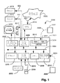
図1は、説明される改竄防止構成が実現可能な汎用コンピュータを概略的に示すブロック図である。改竄防止方法は、図1に示すような汎用コンピュータシステム2200を使用して実現されることが好ましい。この場合、図3、図4、図6、図7、図12〜図15、図17、図18の処理は、コンピュータシステム2200内で実行する改竄防止アプリケーションプログラム等のソフトウェアとして実現されてもよい。特に、改竄防止方法の工程は、コンピュータにより実行される改竄防止アプリケーションソフトウェアの命令により実行される。命令は、各々が1つ以上の特定タスクを実行する1つ以上のコードモジュールとして構成されてもよい。また、改竄防止アプリケーションソフトウェアは、2つの個別の区分に分割されてもよい。この個別の区分において、第1の区分は、改竄防止方法を実行し、第2の区分は、第1の区分とユーザとの間のユーザインタフェースを管理する。改竄防止アプリケーションソフトウェアは、例えば、以下に説明する記憶装置を含むコンピュータ可読媒体内に格納されてもよい。改竄防止アプリケーションソフトウェアは、コンピュータ可読媒体からコンピュータ内に読み込まれ、コンピュータにより実行される。このようなソフトウェア又はコンピュータプログラムが記録されたコンピュータ可読媒体は、コンピュータプログラムプロダクトである。コンピュータ内のコンピュータプログラムプロダクトの使用は、改竄防止に有用な装置に対して有効である。
FIG. 1 is a block diagram schematically showing a general-purpose computer capable of realizing the falsification preventing configuration described. The tampering prevention method is preferably implemented using a general-
コンピュータシステム2200は、コンピュータモジュール2201と、キーボード2202、マウス2203及びスキャナ2218等の入力装置と、プリンタ2215、表示装置2214及びスピーカ2217を含む出力装置とにより構成される。変調器−復調器(モデム)トランシーバ装置2216は、例えば、電話回線2221又は他の機能媒体を介して接続可能な通信ネットワーク2220との通信のために、コンピュータモジュール2201により使用される。モデム2216は、インターネットへのアクセス、及びローカルエリアネットワーク(LAN)又は広域ネットワーク(WAN)等の他のネットワークシステムへのアクセスの獲得のために使用できる。また、モデム2216は、いくつかの実現例において、コンピュータモジュール2201に内蔵されてもよい。
The
コンピュータモジュール2201は、通常、少なくとも1つのプロセッサユニット2205及びメモリユニット2206を含む。メモリユニット2206は、例えば、半導体ランダムアクセスメモリ(RAM)及び半導体読み取り専用メモリ(ROM)から構成される。また、モジュール2201は、多数の入出力(I/O)インタフェースを含む。多数の入出力(I/O)インタフェースは、ビデオ表示装置2214及びスピーカ2217に接続されるオーディオ/ビデオインタフェース2207と、キーボード2202、マウス2203及び任意のジョイスティック(不図示)用のI/Oインタフェース2213と、モデム2216、スキャナ2218及びプリンタ2215用のインタフェース2208とを含む。いくつかの実現例において、モデム2216は、インタフェース2208内等のコンピュータモジュール2201に内蔵されてもよい。記憶装置2209は、コンピュータモジュール2201内に設けられ、通常、ハードディスクドライブ2210と、フロッピディスクドライブ2211とを含む。更に、コンピュータモジュール2201は、磁気テープドライブ(不図示)を使用してもよい。CD−ROMドライブ2212は、通常、不揮発性データの供給源として設けられる。
コンピュータモジュール2201の構成要素2205から構成要素2213は、通常、関連技術の当業者に知られるコンピュータシステム2200の従来の動作モードが得られるように、相互接続バス2204を介して通信を行う。上述の構成を実現可能なコンピュータの例は、複数のIBM−PCと、IBM−PCの互換機と、Sun Sparcstations又はSun Sparcstationsから派生した類似のコンピュータシステムとを含む。
通常、改竄防止アプリケーションプログラムは、ハードディスクドライブ2210上に常駐する。改竄防止アプリケーションプログラムは、プロセッサ2205により、ハードディスクドライブ2210の作動時に読み取られ、制御される。プログラム及びネットワーク2220から取り込まれた任意のデータの中間格納は、半導体メモリ2206を使用して実現されてもよく、ハードディスクドライブ2210との協働により行われてもよい。いくつかの例において、改竄防止アプリケーションプログラムは、それぞれ、破線2224で示すように、CD−ROM2225上で、又は破線2223で示すように、フロッピディスク2222上で符号化され、且つ対応するドライブ2212又はドライブ2211を介して読み取られた状態でユーザに提供されてもよい。あるいは、改竄防止プログラムは、モデム装置2216を介してネットワーク2220からユーザにより読み取られてもよい。更に、改竄防止アプリケーションソフトウェアは、他のコンピュータ可読媒体からコンピュータシステム2200内に読み込み可能である。本明細書で用いられる「コンピュータ可読媒体」とは、実行及び/又は処理のために、命令及び/又はデータを、コンピュータシステム2200へ提供することに関わる任意の記憶媒体又は送信媒体である。記憶媒体の例には、フロッピディスク、磁気テープ、CD−ROM、ハードディスクドライブ、ROM又は集積回路、光磁気ディスク、又はPCMCIAカード等のコンピュータ可読カードが含まれる。これらの装置は、コンピュータモジュール2201の内部又は外部のいずれに設けられてもよい。送信媒体の例は、無線送信チャネル又は赤外線送信チャネルと、別のコンピュータ又はネットワーク装置へのネットワーク接続回路と、ウェブサイト等に記録された電子メール送信及び情報を含むインターネット又はイントラネットとを含む。
Usually, the falsification preventing application program resides on the
改竄防止技法の好適な構成は、コンピュータシステム2200のような汎用コンピュータシステム上で実行される1つ以上のソフトウェアモジュールとして実現される。しかしながら、改竄防止技法は、複合機等の埋め込み型システムの改竄防止アプリケーションソフトウェアモジュールとして実現されてもよい。また、改竄防止技法は、特定用途向け集積回路又はFPGA(Field Programmable Gate Array)等の固定論理又はプログラマブル固体論理回路により実現されてもよい。
A preferred configuration of the anti-tampering technique is implemented as one or more software modules that execute on a general-purpose computer system, such as
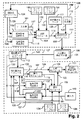
図2は、開示された改竄防止システムの機能ブロック図の一例を示す図である。図2は、不正顕示機能付文書105及び不正顕示機能付文書105’を作成する作成サブシステム126と、不正顕示機能付文書105及び不正顕示機能付文書105’が改竄されたか否かを検知する(妥当性検証を行う)妥当性検証サブシステム127とを有する。
FIG. 2 is a diagram illustrating an example of a functional block diagram of the disclosed falsification prevention system. FIG. 2 shows a
不正顕示機能付文書105を作成する作成サブシステム126を考えると、選択モジュール104は、走査ベースの2値レベルソース信号117の値に応じて、2つの同期させた暗号信号115及び暗号信号116のうちの1つから選択する。信号117は、印刷されるべきソース情報であり、2値レベルソース画像101から導出される。それぞれ、暗号信号115は、暗号信号供給源102により生成されたストリーム暗号であり、暗号信号116は、暗号信号供給源103により生成されたストリーム暗号である。暗号信号供給源102は、鍵生成モジュール134からの矢印135で示すように、秘密鍵ベース情報を受け取る。暗号信号供給源103は、鍵生成モジュール134からの矢印136で示すように、秘密鍵ベース情報を受け取る。鍵生成モジュール134、暗号信号供給源102及び暗号信号供給源103の動作は、図6に関して更に説明される。ソース文書101が紙文書の形態である場合、スキャナ2218(図1を参照)を使用して、信号117を紙文書101から発生させることができる。ソース文書が電子文書形式(Adobe PDF等)である場合、信号117をラスタ画像プロセッサ(RIP)から発生させることができる。RIPは、電子文書を、信号117を形成する画素に変換する。あるいは、ソース画像101が、メモリ(不図示)内にデジタル画像形態で格納された場合、信号117は、走査ベース方式でメモリから読み出すことができる。
Considering the
ソース信号117を使用して、暗号信号115と暗号信号116との間からいずれかの信号を選択することにより、それぞれのルックアップテーブル130及びルックアップテーブル131と関連させて変調された合成暗号信号118を形成する。変調された合成暗号信号118は、ソース情報101の可視摂動バージョンである。本例において、ソース画像101は、黒画素及び白画素で合成された2値レベル画像である。一構成例によると、合成信号118は、「暗」画素及び「明」画素で合成された多値レベル画像を表現する。そのため、一例において、「暗」画素は、黒並びに完全な純色の赤、緑及び青のうちの1色であってもよい。「明」画素は、白、シアン、マゼンダ及びイエロのうちの1色であってもよい。
By using the source signal 117 to select one of the
そのため、ソース画像101が2値レベルである本例において、2つの各暗号信号115及び暗号信号116は、それぞれのルックアップテーブル130及びルックアップテーブル131を介して、非暗号であり且つ相互に識別可能な主成分を有する信号と関連付けられる。信号115及び信号116のうちの他方と関連付けられた主成分は、常時、視覚的に暗い。一方、信号115及び信号116のうちの他方と関連付けられた主成分は、常時、視覚的に明るい。更に、2つの各暗号信号115及び暗号信号116は、それぞれのルックアップテーブル130及びルックアップテーブル131を介して、暗号副成分(例えば、色変化の形態をとる)と関連付けられる。
Therefore, in this example in which the
「非暗号」は、相互に識別可能な複数の主成分が、暗号を考慮せずに互いに区別できることを意味する。 “Non-encrypted” means that a plurality of principal components that can be distinguished from each other can be distinguished from each other without considering encryption.
多値レベル(N段階の異なる色調を有するN値レベル)文書において、N個の暗号供給源102,・・・,103が使用される。N個の各暗号供給源は、それぞれのルックアップテーブルを介して、暗号信号と関連付けられる。この暗号信号は、非暗号であり、且つ相互に識別可能なN個の主成分、及びN個の暗号副成分を有する。
In a multi-level (N-level level with N different tones) document, N cryptographic
図2の2値レベル文書の場合に戻ると、合成暗号信号118は、組み合わせモジュール114内で組み合わせ処理が実行される。生成された合成されたコンポジット信号122は、記録モジュール(図1のプリンタ2215等)により転送媒体上に記録され、本例においては、印刷された不正顕示機能付文書105を形成する。転送媒体は、通常、印刷文書を形成するために使用される紙である。この場合、転送媒体を印刷媒体と呼ぶ。転送媒体の別の例は、銀塩フィルムである。また、合成されたコンポジット信号のデジタル転送も、可能である。
Returning to the case of the binary level document of FIG. 2, the combined
多くの場合、この説明における「文書」という用語は、合成されたコンポジット信号122がプリンタ(図1のプリンタ2215等)により印刷される印刷(転送)媒体を有する印刷文書のコンテキストにおいて使用されるが、文書という用語は、より一般的な意味を有する。従って、文書という用語は、合成されたコンポジット信号122が適切な光学処理及び/又は光学装置を使用して記録された銀塩フィルム(転送)媒体を有する記録文書等にも適用できる。
In many cases, the term “document” in this description is used in the context of a printed document having a print (transfer) medium on which the
更に別の構成において、マーキング処理及び認証処理は、複数のデジタル文書画像の準備、格納、転送及び認証において使用されてもよい。この構成において、開示された改竄防止方法を内蔵するコンピュータアプリケーションは、まず、マーキング処理をデジタル文書画像に適用する。このデジタル文書画像は、走査処理の一部として作成された。しかしながら、このデジタル文書画像は、デジタル手段のみにより作成してもよい。その後、アーカイブ、送信、再符号化(異なるデジタル画像標準への変換等)、再サンプリング(画像スケーリング中に作成する)、及び圧縮又は再圧縮(ベースラインJPEG圧縮等の所謂「非可逆」圧縮を含む)のうちの1つ以上の処理が、文書画像に対して実行される。これらの動作のうちの1つ以上の動作の後、コンピュータアプリケーションは、開示された認証処理、及び第2のコンピュータアプリケーションを使用して表示された結果を使用して、生成された画像を認証してもよい。上述のマーキング処理及び認証処理の使用は、画像変換により画像のデジタルビットパターン又は画像の符号化に重要な変化を施す場合においても、画像の出現に対して有効な可視変化を施さない画像変換に対してロバストである。 In yet another configuration, the marking process and the authentication process may be used in the preparation, storage, transfer and authentication of multiple digital document images. In this configuration, a computer application incorporating the disclosed falsification prevention method first applies a marking process to a digital document image. This digital document image was created as part of the scanning process. However, this digital document image may be created only by digital means. Then archive, send, re-encode (convert to different digital image standards, etc.), re-sample (create during image scaling), and compress or re-compress (so-called “lossy” compression such as baseline JPEG compression) One or more of the above are executed on the document image. After one or more of these operations, the computer application authenticates the generated image using the disclosed authentication process and the result displayed using the second computer application. May be. The use of the marking process and the authentication process described above is an image conversion that does not cause a visible change that is effective for the appearance of an image, even when an important change is made to the digital bit pattern of the image or the encoding of the image by the image conversion. Robust against it.
合成されたコンポジット信号122を構築する暗号信号115及び暗号信号116と関連付けられた主成分は、オリジナルのソース画像101を読み取り可能とした場合と同様の方法によって、人間又は機械が不正顕示機能付文書105を読み取ることを可能とする。ソース画像101内の情報に対する追加としての副摂動成分は、不正顕示機能付文書105内で可視であるが、この摂動が微小なため、人間(又は機械)の読み手又は読取り装置では認識されない。そのため、不正顕示機能付文書105は、ソース画像101から可視摂動が行なわれるが、ソース画像101と明確に等価である。換言すれば、印刷媒体上に印刷された場合に摂動されたソース情報は、人間又は機械により読み取り可能な状態である。
The principal component associated with the
妥当性検証サブシステム127における位置決め処理のロバストさを改善するために、粗位置決め提供源111からの任意の視覚的に微弱な粗位置決め信号128は、組み合わせモジュール114により変調された合成暗号信号118上に重畳される。位置決めが(a)手動登録マーク方法又は(b)精位置決め処理のみのいずれかに依存するため、粗位置決め信号は、任意である。十分な計算資源が利用可能な場合、精位置決め処理のみを使用して位置決めを実現することができる。尚、この方法では、検索を行う必要がある。開示された精位置決め処理は、手動粗位置決め方法又は別の粗位置決め方法を使用して十分に実行される。更に、複数の異なる不正顕示機能付文書105…,105’からの合成信号120の試験により、暗号信号115及び暗号信号116の潜在的な回復を防止するために、暗号信号115及び暗号信号116を生成する秘密鍵(図6のステップ2501を参照)は、2つの要素から作成される。第1の要素は、複数の文書105,・・・,105’のために固定される。この第1の要素は、文書105,・・・,105’の任意の1つに適用されるような妥当性検証サブシステム127により実行される妥当性検証処理に必要とされる。第2の要素は、ソルト生成器112からの「ソルト」値129と呼ばれる。ソルト値は、各文書105,・・・,105’(図6のステップ2508及びステップ2501を参照)に対して固有である。ソルト値の使用は、暗号法分野において公知の技法である。ソルト値129は、組み合わせモジュール114により各不正顕示機能付文書105,・・・,105’の変調された合成暗号信号118内にわずかに埋め込まれる。また、ソルト値129は、矢印142で示すように、鍵生成モジュール134に提供される。ソルト値129は、妥当性検証処理中に粗位置決め/ソルト回復モジュール113により再び回復できる。そのため、妥当性検証サブシステム127による不正顕示機能付文書105の妥当性検証処理は、秘密鍵及びソルト値129の(共通の)第1の要素を必要とする。ソルト値129は、秘密鍵の第2の要素と同様に、不正顕示機能付文書105に対して固有である。不正顕示機能付文書105’の妥当性検証処理は、秘密鍵及びソルト値の(共通の)第1の要素を必要とする。ソルト値は、秘密鍵の第2の要素と同様に、不正顕示機能付文書105’に対して固有である。
In order to improve the robustness of the positioning process in the validation subsystem 127, any visually weak
秘密鍵の共通の第1の要素140は、管理手段(例えば、オペレータに手動で妥当性検証サブシステム127に入力させるために渡された密封封筒内の第1の要素を提供する)等により妥当性検証サブシステム127に提供される。要素140は、矢印141で示すように、暗号信号供給源102’及び暗号信号供給源103’に提供される。各不正顕示機能付文書105からの妥当性検証サブシステム127は、秘密鍵の第2の文書固有要素を抽出できる。
The common
改竄検知(妥当性検証とも呼ばれる)のために使用された妥当性検証サブシステム127に戻ると、走査ベース不正顕示信号120は、図1のスキャナ2218を使用して、作成サブシステム126により作成した不正顕示機能付文書105を走査することにより導出される。信号120は、主成分(オリジナル情報117を反映すると仮定される)及び副成分(選択モジュール104の制御下において、暗号信号115及び暗号信号116により導入されると仮定される)を含む。粗位置決め/ソルト回復モジュール113は、不正顕示機能付文書105の粗位置決めを実行し、「粗位置決め」走査ベース不正顕示機能付文書121を作成する。また、ソルトモジュール113は、信号120からソルト値を抽出し、矢印139で示すように、暗号信号供給源102’及び暗号信号供給源103’にソルト値を提供する。精位置決めモジュール106は、粗位置決め信号121の色成分と、同期させた暗号信号115’及び暗号信号116’、並びにルックアップテーブル134からの色138及びルックアップテーブル135からの色137を組み合わせる(すなわち、平均化する)ことにより作成された信号とを相関させる。尚、色137と色138とは、関連付けられている。図4に関してより詳細に説明するように、上記の組み合わされた暗号信号115’及び暗号信号116’、並びに色137及び色138は、暗号信号115’及び暗号信号116’のカラー画像バージョンを形成する。
Returning to the validation subsystem 127 used for tamper detection (also called validation), the scan-based fraud display signal 120 was created by the
信号115’は、暗号信号供給源102’からの暗号信号であり、信号116’は、暗号信号供給源103’からの暗号信号である。暗号信号供給源102’及び暗号信号供給源103’は、通常、暗号信号供給源102及び暗号信号供給源103から物理的に離間されているが、同一である。精位置決めモジュール106により実行された相関付けにより、粗位置決め不正顕示信号121と暗号信号115’及び暗号信号116’との間の精スケール同期(すなわち、位置決め)は、不正顕示機能付文書105内を人間又は機械が読み取り可能な強力な主成分と独立して実現される。この位置決めは、「精位置決め」走査ベース不正顕示信号123を形成する。
The signal 115 'is an encryption signal from the encryption signal supply source 102', and the signal 116 'is an encryption signal from the encryption signal supply source 103'. The encryption
その後、妥当性検証サブシステム127における妥当性検証処理では、閾化モジュール107を使用して、精位置決め不正顕示信号123内に存在する複数の暗号信号の複数の主成分を識別することにより、2値レベル信号119を形成する。2値レベル信号119は、(オリジナル)2値レベル信号117と仮定される。ソース信号117がN値レベルである場合、仮定文書信号119は、N値レベル信号である。ソース信号117が2値レベルソースの本例では、文書信号119は、2値レベルである。次に、比較モジュール108において、123で示す信号と同一の信号である精位置決め不正顕示信号124は、選択モジュール109の制御下で、第1の暗号信号115’と関連付けられたルックアップテーブル134からの値、又は第2の暗号信号116’と関連付けられたルックアップテーブル135からの値のいずれかの値と比較される。選択モジュール109は、対応する走査位置の信号119の2値レベルの値に従って切り替えられる。選択モジュール109は、対応する走査位置の信号119の2値レベルの値に従って変調された合成暗号信号125を出力する。不正顕示機能付文書105からの信号119の副成分と、対応する変調された合成暗号信号125からの副成分とが一定の許容範囲内で一致しない複数の走査位置(画素位置と呼ばれる)は、妥当性検証信号モジュール110により(例えば、改変の導入を介して)改竄されたことが明らかにされる。
Thereafter, the validity verification processing in the validity verification subsystem 127 uses the
<不正顕示機能付文書形成方法の詳細な説明>
本実施例において、2値レベルソース画像101からの2値レベル信号供給源117は、デジタル形式の白黒文書画像を表現する。この(ソース)画像101は、ラスタ化処理(RIP)提供元、走査提供元又は他の等価の提供元の出力として発信できる。不正顕示機能付文書105を作成するために、このソース画像101の導出を紙転送媒体上にマーキングすることにより、ソース画像101は、不正顕示機能付文書105となる。妥当性検証サブシステム127により実行される妥当性検証(すなわち、改竄検知)処理は、媒体(文書105に対して使用される)がオリジナルのソース画像101の各サンプルに対する3つ以上の識別可能な値を支持する必要がある。従って、オリジナルのソース画像101の解像度を、このような処理が実現されるように設定する必要がある。
<Detailed description of document formation method with fraud revealing function>
In this embodiment, the binary level
不正顕示機能付文書105は、必要な情報を保持可能にするため、十分に高度な解像度を有する必要がある。例えば、プリンタがハーフトーン装置である場合、不正顕示機能付文書105は、装置画素の収集を利用して複数の識別可能な値を得る。
The
実現可能な空間解像度は、印刷技術と共に変化する。電子写真(レーザ)印刷技術及び熱インクジェット技術を含む多くの現代印刷技術に対して、オリジナルのソース画像101の解像度は、約200DPIである。多くの場合において、より高度な解像度は、実現可能である。ソース画像101に対する解像度が低下すると共に、解像度は、徐々によりロバストになる(すなわち、印刷処理及び走査処理に固有の誤り及び劣化の許容度が高くなる)。しかしながら、解像度の品質は、明らかに低い。
The achievable spatial resolution varies with the printing technology. For many modern printing technologies, including electrophotographic (laser) printing technology and thermal ink jet technology, the resolution of the
暗号信号供給源102からの暗号信号115及び暗号信号供給源103からの暗号信号116は、ストリーム暗号から生成された2次元暗号フィールドから導出される。上述の構成において、暗号信号115及び暗号信号116は、52ビット鍵を有するRC4ストリーム暗号のマスタ・インスタンシエーションを使用して生成される。暗号信号115及び暗号信号116は、まず、単一のマスタRC4ストリームから、暗号信号(115等)へ交互バイトを指向させ、且つ次に他の暗号信号(116等)へ指向させることにより生成される。他のストリーム暗号又は擬似ランダムシーケンス生成器は、異なる鍵長さで、交互に利用できる。別の技法の例は、一対の最大期間の線形フィードバックシフトレジスタを使用して、暗号信号115及び暗号信号116を生成することである。この例は、図6に関連してより詳細に説明する。
The
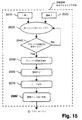
図3は、図2のシステムを使用して、開示された改竄防止方法に係る不正顕示機能付文書を作成する方法ステップのフローチャートとして、プロセス2300を示す。プロセス2300は、ステップ2301で開始する。ステップ2301では、ソース画像101からの次の画素を読み取る。その後、判断ステップ2302では、上記の画素値を判定する。この説明のバルクが2値レベルである場合、ステップ2301において読み取られた画素は、2つの可能な値のうちの1つを有する。しかしながら、一般に、ソース画像101は、N段階のレベルを有することが可能である。そのため、一般に、判断ステップ2302では、ステップ2301において読み取られた画素が、複数のN値のうちの1つの値を有することが可能であることを考慮すると、その画素は、そのうちのどの値を有するかを判定する。ステップ2302において、画素値がBに等しいと判定された場合、プロセス2300は、矢印Bに従って、ステップ2303へ進む。ステップ2303では、(a)画素値に従って暗号フィールドBを選択し、(b)次に、当該画素の位置に依存する上記の暗号フィールドから値を選択し、且つ(c)最後に、多値レベル画素値を判定するために、暗号フィールドBから選択された値を使用してルックアップテーブルBを索引することにより、多値レベル画素値を判定する。続くステップ2311では、この画素値を格納する。その後、プロセス2300は、判断(検査)ステップ2304へ進む。ステップ2304では、ソース画像101内で更なる画素が使用できるか否かが判定される。更なる画素が使用できる場合、プロセス2300は、矢印YESに従って、ステップ2301へ戻る。
FIG. 3 shows a
判断(検査)ステップ2302へ戻ると、画素が値Aを有すると判定された場合、プロセス2300は、矢印Aに従って、ステップ2305へ進む。ステップ2305は、ステップ2303と同様に機能する。その後、プロセス2300は、ステップ2311へ進む。
Returning to the decision (inspection)
判断ステップ2302へ戻ると、画素が値Cを有すると判定された場合、プロセス2300は、破線矢印Cに従って処理ブロック(不図示)へ進む。処理ブロックは、ブロック2303及びブロック2305と等価である。ソース文書101がN段階のレベルを有する一般的な場合において、判断ステップ2302では、N通りの判断のうちの1つを行うことができる。
Returning to
判断ステップ2304へ戻ると、更なる画素が使用できない場合、プロセス2300は、矢印NOに従って、ステップ2307へ進む。ステップ2307では、多値レベル画素データと粗位置決めマーク及びソルト値とを組み合わせる。その後、ステップ2308では、合成されたコンポジット信号を印刷媒体上に印刷する。ステップ2308の結果、破線矢印2309で示すように、不正顕示機能付文書105が得られる(図2を参照)。
Returning to
図4は、図3の不正顕示機能付文書が改竄されたか否かを判定する方法ステップのフローチャートとして、プロセス2400を示す。プロセス2400は、ステップ2430で開始する。ステップ2430では、不正顕示機能付文書105を走査する。その後、ステップ2401では、粗位置決めマークを回復する。その後、ステップ2402では、回復された粗位置決めマークを使用して暗号フィールドに対して不正顕示機能付文書105の粗位置決めを行う。続くステップ2422では、文書105からソルト値を回復する。その後、ステップ2403では、不正顕示機能付文書105と暗号フィールドとの間の精位置決めを行う。精位置決めステップ2403は、3つのサブプロセスを有する。第1のサブプロセス2403Aでは、図15に関してより詳細に説明するように、ブロック相関付けを行うことにより、置換マップを形成する。第2のサブプロセス2403Bでは、図17に関してより詳細に説明するように、置換マップに関して補間を行う。第3のサブプロセス2403Cでは、図18に関してより詳細に説明するように、ワーピングを行うことにより、精位置決め文書を形成する。
FIG. 4 shows a
次のステップ2404では、走査対象の不正顕示機能付文書105の次の画素を読み取る。その後、判断(検査)ステップ2405では、2値レベルソース画像101に対して、画素の主成分が値A又は値Bを有するか否かを検査する。図3に関して説明された場合と同様に、ソース画像101がN段階のレベルを有する場合、判断ステップ2405は、N回の判断ブランチを有する。
In the
本例において、画素の主成分が値Aを有する場合、プロセス2400は、矢印Aで示すように、ステップ2407へ進む。ステップ2407では、上記の画素位置の仮定副成分を判定する。この判定は、当該画素位置の暗号フィールドAを考慮し、且つこの暗号フィールド値を使用して関連ルックアップテーブル(図2の130及び131を参照)を索引することにより行われる。この判定により、仮定副成分が生成される。その後、ステップ2417では、印刷文書105から当該画素位置の実際の副成分値を読み取る。続く判断ステップ2409では、ステップ2407からの仮定副成分値が、ある許容度の範囲内でステップ2417からの実際の読み取り副成分値に等しいか否かが確認される。仮定副成分値が実際の副成分値と等しくない場合、プロセス2400は、矢印NOに従って、ステップ2415へ進む。ステップ2415では、上記の画素位置において改竄が行われたことを宣言する。
In this example, if the principal component of the pixel has the value A, the
判断ステップ2405へ戻ると、画素の主成分が値Bを有すると判定された場合、プロセス2400は、矢印Bに従って、ステップ2411へ進む。ステップ2411は、ステップ2407と同様に、すなわち、当該画素位置の仮定副成分を判定するために、当該画素位置の暗号フィールドBを参照し、且つ暗号フィールド値の使用により図2からの関連ルックアップテーブル130又はルックアップテーブル131を索引することによって機能する。その後、プロセス2400は、ステップ2417へ進む。
Returning to
判断ステップ2409へ戻ると、ステップ2407及びステップ2408からの仮定副成分が、受け入れ可能な許容範囲まで、ステップ2417の印刷文書からの実際の読み取り副成分に等しい場合、プロセス2400は、矢印YESに従って、ステップ2413へ進む。ステップ2413では、関心画素位置において改竄が検知されなかったことを宣言する。その後、プロセスは、矢印2414に従って、ステップ2404へ進む。プロセス2400は、ステップ2415からもステップ2404へ進む。
Returning to
<2次元暗号フィールドの生成>
図5は、2次元暗号フィールド(2次元暗号フィールドとも呼ばれる)の生成を表す図である。図5は、ストリーム暗号から2次元暗号フィールド306及び2次元暗号フィールド307を生成するための2つの方法を示す。暗号フィールドの生成は、図6に関して説明するプロセス2500に従って、暗号信号供給源102及び暗号信号供給源103(図2を参照)により作成サブシステム126において、並びに暗号信号供給源102’及び暗号信号供給源103’により妥当性検証サブシステム127において行われる。
<Generation of two-dimensional encryption field>
FIG. 5 is a diagram illustrating generation of a two-dimensional encryption field (also referred to as a two-dimensional encryption field). FIG. 5 shows two methods for generating the two-
妥当性検証処理において暗号鍵データを使用するため、暗号フィールドを再生できるように、ストリーム暗号を2次元暗号フィールドに変換することが望ましい。特に、オリジナルのソース画像101の走査線の長さに依存することを回避することが望ましい。例えば、ストリーム暗号が、ラスタ順に単純に暗号フィールドに変換された場合、この走査線の長さへの依存は、引き起こされる。また、暗号フィールド306及び暗号フィールド307は、ラスタ順に生成されることが望ましい。暗号フィールド306及び暗号フィールド307は、ソース画像101の公称中心位置に対して生成される。この公称中心位置は、通常、画像101の空間的中心付近に位置決めされるが、必ずしも空間的中心付近ではない。
Since the encryption key data is used in the validity verification process, it is desirable to convert the stream cipher into a two-dimensional encryption field so that the encryption field can be reproduced. In particular, it is desirable to avoid relying on the length of the scan line of the
図5の暗号フィールド306を考慮すると、鍵K1(すなわち、鍵301)は、2つの暗号信号供給源(図2の暗号信号供給源102又は暗号信号供給源103)のうちの1つによる利用のために生成された第1の52ビットシーケンスである。ストリーム暗号の次の52ビットセグメントは、以前に生成された鍵(K1等)上における鍵位置(K2等)、及び以前に生成された鍵(K1等)下における鍵位置(K3等)に、交互に割り当てられる。このようにして、最初の52ビットシーケンス鍵の中心スパイン(Spine)308は、生成される。スパイン308は、垂直方向の任意の所望の長さを有する。これらの各52ビット鍵K1、K2、...、は、生成されるべき暗号フィールド306の水平走査線(走査線305等)と関連付けられる。
Considering the
暗号フィールド306の任意の特定走査線(走査線305等)を生成するために、第2のRC4暗号生成器は、その特定走査線と関連付けられた鍵を使用して初期化される。従って、例えば、302で示される鍵K4は、走査線305に関して使用される。連続多値ビット「S」値は、第2のRC4暗号生成器から生成される。連続多値ビット「S」値は、その走査線上の以前に生成された「S」値の右の(S41等における)「S」値及び次の左の(S42等における)「S」値と交互に関連付けられる。各多値ビット「S」値は、暗号フィールド306内に値(S42等)を形成する。マスタ暗号ストリームとの同期を維持するために、信号供給源102及び信号供給源103と関連付けられた2つの暗号フィールド306及び暗号フィールド306’(後者は不図示)は、同時に生成される。
In order to generate any particular scan line (such as scan line 305) in the
スパイン308は、暗号フィールド306及び暗号フィールド306’を形成するために使用される。しかしながら、スパイン308は、暗号フィールド自体の一部を形成するものではない。暗号フィールド306及び暗号フィールド306’は、「S」値のみにより構成される。スパイン308(すなわち、「K」値)は、52ビット鍵で構成される。「S」値(暗号フィールドを形成する)は、本例において2ビット値である。
暗号フィールドを発生させる他の方法は、可能である。符号307は、別の暗号フィールドを示す。別の暗号フィールドにおいて、符号303は、ラスタグリッド304を埋め込む別の渦巻ベース構成の開始を指示する。この構成307は、単一のストリーム暗号エンジンのみを必要とする点で有用であるが、いくつかの実現例においては特殊バッファリングを必要とする。
Other ways of generating the cryptographic field are possible.
暗号フィールド306及び暗号フィールド307の絶対サイズは、必ずしもソース文書101の大きさと同一ではないが、暗号フィールドのS値は、ソース画像101の画素と「合同」であるとする。この合同において、ソース画像101の各画素と、暗号信号供給源102及び暗号信号供給源103により出力された暗号フィールドの対応するS値との間に固有の1:1対応が成立するようにする。改竄防止方法を行うために、妥当性検証サブシステム127により行われた位置決めは、この合同を再確立する。
The absolute sizes of the
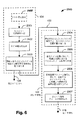
図6は、図5の暗号フィールドのうちの1つを生成する方法ステップのフローチャートとして、プロセス2500を示す。プロセス2500は、図2に関して説明されたように、鍵生成モジュール134及び暗号信号供給源A(すなわち、暗号信号供給源102)により実現される。鍵生成モジュール134へ戻ると、図6の第1のステップ2508では、ソルト値が生成される。ステップ2508の破線アウトラインで示すように、ステップ2508は、任意のステップである。その後、ステップ2501では、ステップ2508のオプションが選択された場合、ソルト値を使用して52ビット秘密鍵を生成する。続くステップ2502では、RC4暗号ストリームを生成する。次のステップ2503では、矢印135で示すように、連続する52ビットバイトの暗号ストリームを、暗号信号供給源102等の連続する暗号信号供給源に割り当てる。矢印136は、交互の52ビットバイトが信号供給源103へ指向されることを示す。
FIG. 6 shows a
信号供給源102において、第1のプロセスステップ2504では、図5に関して説明されたように、鍵生成モジュール134から受け取られた連続する52ビットバイトを、暗号フィールドのスパイン位置に割り当てる。その後、ステップ2505では、スパイン位置ごとに、関連走査線に対してRC4ストリーム暗号を生成する。次のステップ2506では、走査線ストリーム暗号ごとに、連続する2ビットバイトを走査線上の連続する画素位置に割り当てる。その後、ステップ2507では、2ビット暗号フィールド値が出力される。
At
<オリジナル画像と暗号フィールドとの結合>
尚、図2に戻り、特に、選択モジュール104の動作に関して、選択動作(図3の対応するステップ2302、ステップ2303及びステップ2305を参照)として、まず、暗号供給源102及び暗号供給源103からの2つの暗号フィールド、並びにソース画像101からのオリジナル画像は、暗号フィールド及びオリジナル画像の公称中心位置上に位置決めされる。選択段階(図3のプロセス2312に対応)において、位置決め位置の選択は、公称である。しかしながら、選択された位置決め位置は、不正顕示機能付文書105内へロックされ且つ符号化された状態となり、妥当性検証サブシステム127による回復処理(図4を参照)における位置決めのベースを形成する。
<Combination of original image and encryption field>
Returning to FIG. 2, in particular, regarding the operation of the
好適な構成において、暗号信号供給源102及び暗号信号供給源103(図2を参照)により生成された2つの各2次元暗号フィールド(暗号フィールド306(図5を参照)等)内の各値は、2ビット精度を有する。そのため、説明される例において、ソース情報117は、1ビット精度を有する2値レベルである。一方、不正顕示機能付文書105は、各々が2ビット精度を有する2組の4値レベルを有する。2組の4値レベルは、各ソース文書画素の対応する印刷形態に対して合計8つの可能な状態を与える。暗号信号(図2の暗号信号115及び暗号信号116等)が各入力画素(図2のソース画像101からの信号117において)に関するので、各暗号信号に対する状態(すなわち、この例では振幅解像度)の数は、変化する。好適な構成は、4つの状態(そのため、2ビットである)を使用するが、2つ以上のいずれの状態の数であっても効果的である。
In a preferred configuration, each value in each of the two two-dimensional cipher fields (such as cipher field 306 (see FIG. 5)) generated by
偽造者が、画素値を黒から白へ、又は白から黒へ変化させる場合、暗号値115及び暗号値116に対して使用する状態の数の選択は、不正顕示機能付文書105上の印刷画素の副信号の正しい値を「推測」する偽造者の能力に影響を及ぼす。本例における2ビットの選択が、偽造者が75%の時間を誤って推測する可能性があることを意味するので、その選択は、画素集合が小さい場合においても、偽造の強力な指示を提供できる。
When the counterfeiter changes the pixel value from black to white or from white to black, the selection of the number of states to be used for the
多値レベル(すなわち、1画素当たり2ビット以上を有する)不正顕示機能付画像組み合わせ信号122(図2を参照)は、関連暗号信号供給源102及び関連暗号信号供給源103により出力された対応する暗号フィールドからの関連暗号信号値115又は関連暗号信号値116を使用して、それぞれのルックアップテーブル130及びルックアップテーブル131を索引することにより、オリジナルのソース画像101の画素ごとに生成される。好適な構成において、不正顕示機能付文書105を印刷するために使用された出力装置は、プリンタ2215である。本例では、プリンタ2215は、カラープリンタである。不正顕示機能付文書105上の多値レベル画像は、本実施例において、24ビットRGB画像である。
An image combination signal 122 (see FIG. 2) with a tampering function that has a multilevel level (that is, having 2 bits or more per pixel) corresponds to the corresponding encryption
図7は、暗号信号供給源102及び暗号信号供給源103、並びに信号供給源102及び信号供給源103のそれぞれのルックアップテーブル130及びルックアップテーブル131(図2を参照)に関連して、選択モジュール104が動作する方法の特定例406を示す図である。プロセス406では、ソース情報117内の2値レベル画素値を、変調された合成暗号信号118(図2を参照)内の多値レベル画素値に変換する。矢印2315(図3を参照)は、ステップ401へリードする。ステップ401では、オリジナルのソース画像101の画素を考慮する。考慮中の画素が黒である場合、プロセス406は、矢印「Yes」に従って、ステップ402へ進む。ステップ402では、B(黒)暗号フィールドより、考慮中の画素と関連付けられた暗号フィールド内の位置から2ビット値を選択する。しかしながら、画素が白である場合、プロセス406は、矢印「No」に従って、ステップ403へ進む。ステップ403では、W(白)暗号フィールドより、考慮中の画素と関連付けられた位置から2ビット値を選択する。ステップ401〜ステップ403は、それぞれの暗号供給源102(図2を参照)からの暗号信号115と、暗号供給源103(図2を参照)からの暗号信号116との間の選択を行う選択モジュール104により実行される。
FIG. 7 illustrates the selection in relation to the
考慮中の画素が黒である場合、ステップ402において暗号フィールド「B」から選択された2ビット暗号値を使用して、差分ルックアップテーブル404を索引する。ルックアップテーブル404内の画素は、全て、黒又は何らかの暗色のいずれかである。好適な構成において、この画素には、黒並びに完全な純色の赤、緑及び青が使用される。考慮中の画素が白である場合、ステップ403において暗号フィールド「W」から選択された暗号値を使用して、差分ルックアップテーブル405を索引する。ルックアップテーブル405内の画素は、全て、白又は何らかの明色のいずれかである。好適な構成において、この画素には、白、シアン、マゼンダ及びイエロが使用される。これらの色が使用されるのは、人間の目又は自動ビデオ抽出技法の使用のいずれによっても、視覚的な相互識別が容易であるためである。この色選択の結果、ロバストな妥当性検証システム127が得られる。しかしながら、この色選択では、他の色が使用されてもよい。ルックアップテーブル404及びルックアップテーブル405は、図2のルックアップテーブル130及びルックアップテーブル131の特定例である。
If the pixel under consideration is black, the differential lookup table 404 is indexed using the 2-bit cipher value selected from the cipher field “B” in
例えば、ステップ402において、B暗号フィールドから暗号値「10」が発生した場合、この値「10」は、「10」における(RGB)ルックアップテーブル404を索引する。これにより、赤(R)チャネルがFF(16進法において)であり、緑(G)チャネルが00であり、且つ青(B)チャネルが00である出力が得られる。この出力は、赤の出力に等しい。
For example, if an encryption value “10” occurs from the B encryption field in
ステップ401〜ステップ405では、ステップ2311(図3を参照)において格納された多値レベル画素値を発生させる。その後、プロセス406は、矢印2314(図3を参照)に従って、処理を進める。
In
また、非色ベース方式も使用できる。例えば、完全なグレースケール方式において、不正顕示機能付文書に対して印刷及び走査が行われた後、大多数の場合に異なる階調間を識別可能であれば、この異なる階調を使用できる。別の使用可能な方法は、各ソース文書画素に対応するセル内の2値レベル(通常、黒及び白)装置画素の1組の小パターンである。小パターンのうちの1つは、暗号フィールドの各状態を示す。
A non-color based method can also be used. For example, in a complete gray scale method, after printing and scanning are performed on a document with a fraud revealing function , different gradations can be used if different gradations can be distinguished in the majority of cases. Another usable method is a set of small patterns of binary level (usually black and white) device pixels in the cell corresponding to each source document pixel. One of the small patterns indicates each state of the cipher field.
図8は、2値レベル画像701(図2のソース画像101と関連付けられた2値レベル画像等)の多値レベル画像705(不正顕示機能付文書105と関連付けられた多値レベル画像等)への変換の描画表現を示す図である。オリジナル画像701(図2のソース画像101の特定例)は、画素単位ベースで選択モジュール704(図2の選択モジュール104の特定例)を制御するために使用される。
FIG. 8 shows a multilevel image 705 (a multilevel image or the like associated with the
選択モジュール704は、画像701からの画素値706により制御された1画素ベースで、2つの暗号フィールド由来カラーグリッド702及び暗号フィールド由来カラーグリッド703の色オプションから選択する。カラーグリッドは、次のようにして生成される。「黒」色グリッド702内の画素位置707に対する画素値は、「黒」暗号フィールド(不図示)内の上記の画素位置707に対する対応する暗号値を使用して判定される。黒暗号フィールドは、対応する暗号供給源102により生成された暗号フィールド115の特定例である。黒暗号フィールドからの上記の暗号値は、図7のテーブル404と同様に、対応するルックアップテーブル(不図示)内に多値レベル色値を索引するために使用される。「白」色グリッド703内の画素位置707’に対する画素値は、「白」暗号フィールド(不図示)内の上記の画素位置に対する対応する暗号値を使用して判定される。これにより、図7のテーブル405と同様に、対応するルックアップテーブル(不図示)内に多値レベル色値を索引する。
The
オリジナル画像701内の画素位置708における画素値が白であるため、選択モジュール704は、不正顕示機能付画像705内の画素位置708’において挿入されるべきカラーグリッド703内の画素位置707’の色値を選択する。
Since the pixel value at the
複数の画素709は、改竄検知に関して図19に関連させて説明される。
The plurality of
<粗位置決めマーク>
図9は、粗位置決めに使用された2次元線形波形関数の2値レベル表現を示す図である。図2の妥当性検証サブシステム127において使用された精位置決めモジュール106により行われた精位置決めを支援するために、図9の波形関数を使用した粗位置決めマークは、粗位置決め提供元111及び組み合わせモジュール114により合成暗号信号118内に組み込まれる。これにより、不正顕示機能付文書105(図2を参照)上に印刷された多値レベル画像を形成する。好適な構成において、図9に示す関数を使用した微弱な粗位置決めパターン画像は、組み合わせモジュール114により、変調された合成暗号信号118(図2を参照)と混合される。この画像混合は、変調された合成暗号信号118内の各画素値の1つ以上のカラーチャネルに適切な値を加算することにより、あるいは、カラーチャネルから適切な値を減算することにより、行われる。加算量は、非常に小さいため、妥当性検証処理127において閾化モジュール107により行われる複数の色間の識別に影響を与えない。位置決めパターンは、図9に示す複数の1次元スケール不変関数の特定構成から形成される。1次元スケール不変関数は、フーリエ法を使用して効率的に検出できる。選択された1次元スケール不変関数の特定構成は、関数の対称軸が、アフィン変換下において不変である一定長さ比を有する線セグメントを規定する点で交差するように選択される。アフィン変換は、図12に関して、特に、ステップ1790に関して、更に説明される。
<Coarse positioning mark>
FIG. 9 is a diagram showing a binary level representation of a two-dimensional linear waveform function used for coarse positioning. To assist the fine positioning performed by the
位置決めパターン画像は、図9に示すように、4つの1次元スケール不変パターンの重ね合わせである。1次元スケール不変パターンは、横方向に延在して図2のソース画像101を被覆する。単一の1次元スケール不変パターンは、数学的に次式により表される。
![]()
![]()
図10は、図9に示した線形波形関数のグラフィック表現を示す図である。尚、横方向に延在した1次元スケール不変パターンは、2つのパラメータ、すなわち、パターン半径r及びパターン角度αにより特定される。このようなパターンの2次元関数形態(図9に示す)は、数学的に次式により表される。
![]()
![]()
所望の位置決めパターン(図2の信号128において)を形成するために重ね合わせされた4つの1次元スケール不変パターンは、1次元スケール不変パターンに、相互に関連した特定の空間的構成(図11を参照)を与えるrパラメータ値及びαパラメータ値を有する。特定の空間的構成は、位置決めパターン128が組み込まれた不正顕示機能付文書105の位置決めを判定する際に好都合である。この空間的構成は、図11において表現される。
The four one-dimensional scale-invariant patterns superimposed to form the desired positioning pattern (in
図11は、配列検出の際に使用された複数の線形波形関数に基づく対称軸の構成を示す図である。図14に関して更に説明されるように、これらの対称軸を確立するパラメータの組は、特に、対称軸が、アフィン変換下において不変である一定長さ比(比1101:1102により例証される)を有する線セグメントを規定するように選択される。 FIG. 11 is a diagram illustrating a configuration of a symmetry axis based on a plurality of linear waveform functions used in array detection. As further described with respect to FIG. 14, the set of parameters that establish these axes of symmetry, in particular, has a constant length ratio (illustrated by the ratio 1101: 1102) where the axis of symmetry is invariant under the affine transformation. Is selected to define the line segment it has.
好適な構成において、オリジナルのソース画像101は、幅(x)寸法及び高さ(y)寸法の両方において、少なくとも1,024画素の最小画素寸法を有する。しかしながら、最小画素寸法は、いずれか又は両方の寸法において、より大きくてもよい。この最小画素寸法は、以下の式において、Nminとする。一般に、ソース画像101は、幅N画素及び高さM画素の寸法を有する。この場合、M≧Nmin且つN≧Nminである。位置決めマーク128を形成するために使用された4通りのパターンに対するパターンパラメータr値及びパターンパラメータα値は、次式により表される。

![]()
![]()
また、ナイキスト半径RNYQも、特定される。ナイキスト半径は、パターン対称軸に基づく画素数である。この場合、パターン周波数は、画像のナイキスト周波数に等しい。対称軸から第1の可視波形までの距離は、ナイキスト周波数を表す。 A Nyquist radius R NYQ is also specified. The Nyquist radius is the number of pixels based on the pattern symmetry axis. In this case, the pattern frequency is equal to the Nyquist frequency of the image. The distance from the axis of symmetry to the first visible waveform represents the Nyquist frequency.
j番目のパターンに対して、パラメータrj及びパラメータαjを使用すると、中間量Dj、Xj、Yj及びRjは、
オフセット(x,y)における画素に対するj番目のパターンの「影響」Pj(x,y)は、
改竄防止方法を効果的に実行可能とした状態で、ソース画像101が受け入れ不可能な程度まで変形されることを防止するために、パターン影響を使用して、位置決め信号128及びソルト信号129を適切にスケーリングする。
In order to prevent the
<ディクショナリ攻撃防止のためのソルト値加算>
図2へ戻ると、同一の暗号鍵(図6のステップ2501により生成された鍵等)が2ページ以上の不正顕示機能付文書105を生成するために使用された場合、暗号信号供給源102及び暗号信号供給源103により生成された暗号フィールド115及び暗号フィールド116は、文書105の異なるページから明領域及び暗領域を採取することにより潜在的に発見できる。この可能性を防止するために、好適な構成では、ソルト生成器112により提供されるソルト値を採用する。ソルトは、ディクショナリ攻撃を防止するための暗号法の分野において知られる技法である。ソルト技法は、このように、不正顕示機能付文書105の異なる2ページ上の暗号ストリームの類似性に基づいた攻撃を防止する場合においても使用できる。
<Salt value addition for dictionary attack prevention>
Returning to FIG. 2, if the same encryption key (such as the key generated in
好適な構成において、例えば、図6のステップ2501により生成された鍵は、不正顕示機能付文書105の生成器(すなわち、作成サブシステム126のユーザ)及び不正顕示機能付文書105の妥当性検証者(すなわち、妥当性検証サブシステム127のユーザ)によく知られていることが望ましい。しかしながら、不正顕示機能付文書105の2ページに対する暗号ストリームの類似性に基づいた攻撃を防止するために、不正顕示機能付文書105の各ページに対して異なる鍵を使用する必要がある。これらの両方の目的を達成するために、好適な実施の形態では、鍵を2つの要素で形成する。例えば、40ビットの長さの鍵の第1の要素は、作成サブシステム126及び妥当性検証サブシステム127の両方によく知られる。この第1の要素は、不正顕示機能付文書105の各ページに対して同一である。鍵の残る要素、すなわち、この例では12ビット長さのソルトは、不正顕示機能付文書105の各ページに対して異なる。このソルトは、不正顕示機能付文書105の各ページに対して暗号的に(すなわち、「乱」数を効果的に使用して)生成される。ソルト値は、暗号化されない状態で関連ページ内に埋め込まれる。図6のステップ2501により生成された実際の52ビット鍵は、固定40ビットと12ビットソルトとの連接結果である。この実際の52ビット鍵は、作成サブシステム126の各信号115及び信号116、並びに妥当性検証サブシステム127の各信号115’及び信号116’に対して使用されたものである。
In the preferred configuration, for example, the key generated in
暗号的に(ランダムに)生成された12ソルトビットは、2つの6ビット部分Sa及び6ビット部分Srに分割される。それぞれ、6ビット部分Saは、図9に示すスケール不変パターンと類似する第5のスケール不変パターンの角度を表し、6ビット部分Srは、図11に示すスケール不変パターンと類似する第5のスケール不変パターンの位置を表す。Sa及びSrの両方には、64個の異なる値を仮定できる。特定角度及び特定位置を有するこの第5のスケール不変パターンが、信号118内に埋め込まれることにより、作成サブシステム126の不正顕示機能付文書105は、形成される。妥当性検証サブシステム127は、この第5のスケール不変パターンを抽出することにより、パターンの関連角度及び関連位置を判定する。この角度及び位置は、2つの6ビットソルト値部分を確立する。第5のスケール不変パターンは、特に、他の4つのパターンに対して説明した方法と同様の方法で埋め込まれるが、振動定数γが異なる場合を除く。
第5のスケール不変パターンの異なる振動定数の選択は、ソルト値と粗位置決めパターンとの間の検知空間におけるある程度の分離を引き起こす。干渉は、粗位置決めマークにおいて使用された角度に近似する特定角度を無効にすることにより、更に低減させることが可能である。 Selection of different vibration constants of the fifth scale invariant pattern causes some degree of separation in the sensing space between the salt value and the coarse positioning pattern. Interference can be further reduced by defeating a specific angle that approximates the angle used in the coarse positioning mark.
<粗位置決めとソルトパターンとの組み合わせ>
図2の組み合わせモジュール114の機能へ戻ると、位置決めパターン及びソルトパターンにより引き起こされたネット影響は、次式の合計
Returning to the function of the
この値は、−5から5までの範囲で変化する。次に、この値は、−15から15の範囲までスケールアップされ、組み合わせモジュール114により、変調された合成暗号信号118の各チャネルに直接加算される。変調された合成暗号信号118は、多値レベルRGB画像であり、0...255の範囲まで結果をクランピングする。このスケーリング演算は、文書105内のオリジナルのソース情報101を過度に摂動させない状態で、粗位置決めマーク及びソルト値を文書105から抽出することを可能とする。
This value varies in the range from -5 to 5. This value is then scaled up to the range of −15 to 15 and added directly by the
<マーキング処理の結果>
図2の信号122における最終の多値レベル画像は、カラープリンタ2215を使用して不正顕示機能付文書105上に印刷される。カラープリンタ2215は、例えば、Canon IR C3200電子写真複合機又はCanon i950熱インクジェットプリンタであってもよい。プリンタ解像度に対する200DPI画像のスケーリングは、単純な画素複製を使用して実現されることが好ましい。例えば、Canon IP C3200は、600DPIの装置解像度を有する。このプリンタでは、最終の多値レベル画像の各200DPI画素は、Canon IP C3200装置画素の3×3グループ内に複製される。
<Result of marking process>
The final multilevel image in the
組み合わせモジュール114により行われたマーキング処理の結果は、オリジナル2値レベルデジタル画像101の黒値及び白値に対応する明領域及び暗領域の効果により、人間が読み取り可能な印刷文書105である。このマーキングの例は、図8に示される。
The result of the marking process performed by the
尚、図8へ戻ると、それぞれ、画素位置707’等の明領域及び画素位置707等の暗領域は、各々が副成分を含む。それぞれの副成分は、画素位置707’における単方向断面線、及び画素位置707における双方向断面線により示される。これらの副成分を生成する鍵が非存在中の副成分は、有用な情報を含まず、この副成分の偽造は、困難である。しかしながら、2つの副成分の存在間に正確な相関性は存在し、各画素の全体の暗度及び明度は、それぞれ、各画素における主成分を表現する。それぞれの主成分及び副成分の知識を有する検査者は、この相関性の存在又は不足を認証できる。偽造者が関連副成分を相応に変化させることはできないため、偽造者は、画素(すなわち、主成分に対する)を明領域から暗領域へ(又は暗領域から明領域へ)適切に変化させることができる可能性は少ない。偽造者が、既定の画素位置における別の主成分に対する副成分の値を知らないため、偽造者は、相関性を維持することができない。
Returning to FIG. 8, each of the bright area such as the
<認証処理>
図2の妥当性検証サブシステム127へ戻ると、まず、カラースキャナ2218(図1を参照)により、認証されるべき不正顕示機能付文書105を走査することにより、24ビットRGB不正顕示信号120を発生させる。スキャナ2218の走査解像度は、オリジナル画像101の解像度より高いか、又は画像101の解像度に等しいことが要求される。好適な構成において、200DPIオリジナル画像101(図2を参照)の全体にわたり大きなマージンを提供する600DPIスキャナ2218は、使用される。
<Authentication process>
Returning to the validity verification subsystem 127 of FIG. 2, first, the color scanner 2218 (see FIG. 1) scans the
<粗位置決め処理の概要>
図2の粗位置決め/ソルト回復モジュール113の動作へ戻ると、粗位置決めパターン(本実施例において、組み合わせモジュール114により、わずかに不正顕示機能付文書105の印刷前の信号118に加算された4つの位置決めマークを有する)に検出及び解析を施すことにより、走査文書120の方向を暗号フィールドと関連付けるアフィン変換を発生させる。
<Outline of coarse positioning process>
Returning to the operation of the coarse positioning /
図12は、図2の粗位置決め/ソルト回復モジュール113により行われた図4の粗位置決め処理2419を示す図である。走査不正顕示信号120の輝度チャネルの形態の走査文書は、ステップ1710において、まず、幅及び高さの最小値が256画素から511画素の範囲内になるように調整されるまで、生成された画像が、連続半減処理により、リサイズされる。半減処理は、信号120の形態の画像を低域フィルタで畳み込み、且つ畳み込みの結果を間引くことにより行われてもよい。
FIG. 12 is a diagram showing the
次に、生成されたリサイズ画像は、ステップ1720において、2次元高速フーリエ変換(FFT)が施される。この結果は、ステップ1730において、準極周波数空間中に再サンプリングされる。ステップ1730では、バイキュービック補間を使用してFFTを極グリッド上に再サンプリングすることにより、ステップ11720から2次元FFTの極変換を直接使用できる。この方法は、演算が単純な一方で、検知に悪影響を及ぼす可能性のあるアーテファクトを発生させる。ステップ1730において使用された好適な準極方法は、図13に関して説明される。
Next, in
ステップ1720においてFFTを計算する前に、画像縁部に近接する画像値(強度)は、まず、減衰されることが好ましい。この減衰は、画像値が、画像縁部に向かうと共に徐々に且つスムーズにゼロにフェードするように行われる。ステップ1730では、水平列が、ステップ1720で得られた2次元FFTにおける半径スライスに対応する複素画像を作成する。角度スペーシング及び半径スケーリングは、一定である必要はない。
Prior to calculating the FFT in
ステップ1750において、ステップ1740により与えられた1次元基底関数の1次元フーリエ変換は、実行される。ステップ1740により与えられた基底関数は、数学的に次式により表される。
![]()
![]()
次に、ステップ1750から得られた基底関数の変換は、ステップ1760において、画素単位で、全ての角度値に対する水平列(2次元FFTの半径線を表現する)に沿ったステップ1730の出力値の複素共役で乗算される。その後、生成された複素画素値は、ステップ1760により、複素画素値が大きくとも単位大きさを有するように基準化される。次に、ステップ1770では、水平列に沿ったステップ1760の出力の1次元逆高速フーリエ変換(IFFT)を判定する。
Next, the transformation of the basis function obtained from
ステップ1770の結果、図2の走査文書信号120内の1次元基底関数(すなわち、4つの位置決めマーク)の方向及びスケールに対応する画像の大きさにピークを有する複素画像が得られる。これらのピークは、ピーク検出処理1780(図14に関してより詳細に説明される)を使用して検出される。最後に、ステップ1790において、ステップ1780で検出されたピークの位置を使用して、図2の信号120における走査文書を、図2の暗号フィールド115’及び暗号フィールド116’のデジタル形態と関連付けるアフィンパラメータを判定する。
As a result of
ステップ1790において、交点のアフィン変換に最小二乗適合度を与える4つのピークの結合に対応するアフィン変換は、図2の信号120における走査文書の方向を図2の暗号フィールド115’及び暗号フィールド116’の方向と関連付けるアフィン変換として選択される。最小二乗適合度の詳細は、後述される。
In
次に、図4のステップ2402において、アフィン変換が使用され、バイキュービック補間を使用して走査文書が変換される。走査文書の変換により、粗位置決め走査文書を表す信号121(図2を参照)が形成される。この文書は、本例において、約600DPIの解像度を有する。
Next, in
<準極マッピング処理の詳細>
前述の構成において、粗位置決めに対する不変パターンマッチングを行う好適な方法では、チャープZ変換を使用してステップ1720により行われるフーリエ変換の準極変換(図12のステップ1730を参照)を提供する。チャープZ変換は、信号のフーリエ変換のスケーリング部分を計算するための方法である。
<Details of quasi-polar mapping process>
In the above arrangement, a preferred method of performing invariant pattern matching for coarse positioning provides a quasipolar transformation of Fourier transform (see
図13は、図12のステップ1730をより詳細に示す図である。図13は、フーリエ変換の準極マッピングを算出するための準極変換を行うプロセスである。ステップ1810において、図12のステップ1720により出力された大きさ(X,Y)を有するリサイズ画像1801は、2つのコピーI1(符号1802により示される)及びコピーI2(符号1803により示される)として複製される。ステップ1820において、第1のコピーI1を、幅W=2*MAX(X,Y)までX方向にゼロでパディングすることにより、大きさ(W,Y)の画像1804を得る。パディングは、コピーI1の列オフセット
![]()
![]()
![]()
![]()
ステップ1830において、第2のコピーI2を、高さWまでY方向にゼロでパディングすることにより、画像1805を形成する。ステップ1840において、画像1805を90°回転させることにより、大きさ(W,X)の画像1806が得られる。パディングは、コピーI2の行オフセット
![]()
![]()
![]()
![]()
ステップ1850及びステップ1860において、画像1804及び画像1806を、各行の1次元フーリエ変換計算により変換することにより、それぞれ、画像1804の変換画像1807及び画像1806の変換画像1808を形成する。
In
ステップ1870及びステップ1880において、画像1807及び画像1808を、各列の個別のチャープZ変換計算により変換することにより、それぞれ、画像1807の変換画像1809及び画像1808の変換画像1811を形成する。
In
ステップ1870及びステップ1880により行われた各チャープ変換を行うことにより、それぞれのステップ1870及びステップ1880の列の範囲内の位置
ステップ1870及びステップ1880における各列 に対するスケーリング係数は、
![]()
![]()
![]()
![]()
![]()
![]()
不正顕示機能付文書105からの正方形画像を仮定すると、変換画像1809及び変換画像1811は、リサイズされ、ウィンドウ化され、且つ変換画像1809及び変換画像1811を有する入力画像のフーリエ変換の準極変換を表現する。変換画像1809は、[−π/4..π/4] の範囲内の角度を有し、変換画像1811は、[π/4..3π/4]の範囲内の角度を有する。不正顕示機能付文書105からの画像が矩形である場合、角度の範囲は、[−atan2(Y,X)..atan2(Y,X)]及び[atan2(Y,X)..π−atan2(Y,X)]から変化する。準極変換の各行が、正半径及び負半径を含むため、各行は、全て[0..2π]ラジアンの範囲内の角度を有する。
Assuming a square image from the
ステップ1890において、画像1812の上部に画像1809の画素を複製し、且つ画像1812の下部に画像1811の画素を複製することにより、2つの入力画像1809及び入力画像1811を結合して、(W,Y+X)寸法の画像1812を形成する。
In
<ピーク検出処理の詳細>
図14は、図12のピーク検出処理1780の一例を示す流れ図である。図12のステップ1770の結果、図2の走査文書信号120内の1次元基底関数(すなわち、4つの位置決めマーク)の方向及びスケールに対応する画像の大きさにピークを有する複素画像は、得られる。そのため、ピーク検出ステップ1780への入力は、上記の複素画像である相関画像1610で示される。複素画像において、P個の最大ピーク(好適な構成において、Pは64である)の位置の決定が所望される。換言すれば、P個の最大ピークは、相関画像の大きさのP個の最大局所極大である。
<Details of peak detection processing>
FIG. 14 is a flowchart showing an example of the
ピークは、多数のピークが相互に近接集合したノイズのある領域において発生する。一定の閾半径内の最大ピークのみを考慮することにより、10個の画素のデフォルトの閾半径が選択されることが好ましい。ステップ1620において、相関画像1610は、走査され、画素値の大きさが画素値の全ての隣接値より大きい点のリストが、構築される。次のステップ1630において、このピークのリストは、画素値の大きさ順にソートされる。次のステップ1640において、ソートリストの各ピークは、大きさの降順に考慮され、半径距離閾値内のリスト上のソート後の任意のピークは、ピークリストから排除される。次のステップ1650において、ステップ1640で発生したピークのソートリストは、切り捨てられ、長さリストPとなる。
The peak occurs in a noisy region where a number of peaks are close together. A default threshold radius of 10 pixels is preferably selected by considering only the largest peak within a certain threshold radius. In
上記の切り捨てリストは、高精度で決定可能なP個のピークの位置を含む。ステップ1660において、ループ入力により、同様にP個の各ピークを取り入れる。次のステップ1670において、考慮中のピークの位置にセンタリングされた27画素単位の領域は、FFTに入力され、その後、係数27により、ピークに焦点を合わせてズーミングするチャープZ変換に入力される。チャープZ変換は、任意のスペーシングでの離散フーリエ変換(DFT又は逆DFT)の計算を可能にする。チャープZ変換は、例えば、DFTを離散周期的畳み込みとして表現することにより行われる。このような畳み込みが、複数のFFTを使用して実現可能であるため、全体の計算には、FFT速度を利用できる。スペーシングの適切な選択により、チャープZ変換は、例えば、DFTを選択領域全体にわたり精密にサンプリングする(すなわち、ズーミングする)ことが可能な補間技法となる。
The truncation list includes the positions of P peaks that can be determined with high accuracy. In
最大の大きさを有する27画素単位の画像は、次のステップ1680において判定され、このピークのサブ画素位置は、双放物適合を使用して判定される。このサブ画素精度ピーク位置は、ピーク検出ステップ1780の出力である。
The 27 pixel unit image with the largest size is determined in the
<粗位置決めを判定するための検出ピークの使用>
その後、図14のステップ1780(図12も参照)から出力されたピークは、図12のステップ1790により、4つのピークの各可能な結合を順次選択し、且つ次の解析を行うことにより、更に処理される。これにより、4つのピークの結合のうちのこの解析の条件を最も満足する経路を保持する。
<Use of detection peak to determine coarse positioning>
Thereafter, the peak output from step 1780 (see also FIG. 12) of FIG. 14 is further selected by sequentially selecting each possible combination of the four peaks and performing the following analysis in
各ピークsi及びピークβiの半径及び角度は、図13の準極マップ1812内の各ピークのオフセット(x,y)から計算される。
The radius and angle of each peak s i and peak β i are calculated from the offset (x, y) of each peak in the
1813の準極座標(x,y)から極座標(s,β)へのこの変換は、次式により計算される。 This transformation from 1813 quasi-polar coordinates (x, y) to polar coordinates (s, β) is calculated by the following equation:
入力画像1812は、大きさ(W,X+Y)画素の画像であり、次のパラメータ
もし、y<Yである場合は、
線形変換パラメータ(a11、a12、a21、a22、x0、y0)により説明されるアフィン変換は、4つの選択ピークから判定される。線形変換パラメータは、1次元基底関数のパラメータri及びパラメータαiの最初の組(式(3)からの組であり、便宜上式(14)で再生される)を、パラメータsi及びパラメータβiにマッピングする。位置決めマークが埋め込まれた不正顕示機能付文書105において使用された1次元基底関数パラメータの予め規定された組は、式(3)から次式により再生される。
![]()
The affine transformation described by the linear transformation parameters (a 11 , a 12 , a 21 , a 22 , x 0 , y 0 ) is determined from the four selected peaks. The linear transformation parameters are the first set of parameters r i and parameters α i of the one-dimensional basis function (the set from equation (3), reproduced for convenience in equation (14)), parameter s i and parameter β. Map to i . A predetermined set of one-dimensional basis function parameters used in the
![]()
このパラメータの組は、パラメータの組が表現する1次元基底関数の対称軸が、アフィン変換下において不変である一定長さ比を有する線セグメントを規定する点で交差するように、特定の方法で選択されている。 This set of parameters is in a specific way so that the symmetry axis of the one-dimensional basis function represented by the set of parameters intersects at a point that defines a line segment with a constant length ratio that is invariant under affine transformation. Is selected.
4つのピークの結合が満足すべき第1の条件は、4つのピークが、正確な長さ比(例えば、図11の1101:1102を参照)を有する線セグメントの組を生成することである。4つのピークが、正しい長さ比を有する線セグメントの組を生成しなかった場合、ピーク結合が、アフィン変換により変形された4つのオリジナルベースパターンに対応せず、この結合は、破棄される。 The first condition that the combination of the four peaks should satisfy is that the four peaks produce a set of line segments that have the exact length ratio (see, eg, 1101: 1102 in FIG. 11). If the four peaks did not produce a line segment set with the correct length ratio, the peak combination does not correspond to the four original base patterns deformed by the affine transformation, and this combination is discarded.
前述したように、ピークの半径座標si及び角度座標βiは、不正顕示機能付文書内に埋め込まれた1次元スケール不変パターンのうちの1つの対称軸を表す。これらの線パラメータにおける変化を直接通して画像に適用されたアフィン変換が判定されるのではなく、アフィン変換は、4つの選択ピークにより特定された4つの対称軸の交点から判定される。2つの対称線{sk,βk}の軸と対称線{sm,βm}の軸との交点は、(xkm,ykm)でラベル付けされ、次の行列式(16)
As described above, the radius coordinate s i of the peak and the angle coordinate β i represent one symmetry axis of the one-dimensional scale invariant pattern embedded in the document with the fraud revealing function . Rather than determining the affine transformation applied to the image directly through changes in these line parameters, the affine transformation is determined from the intersection of the four symmetry axes identified by the four selected peaks. The intersection of the axis of the two symmetry lines {s k , β k } and the axis of the symmetry line {s m , β m } is labeled with (x km , y km ), and the following determinant (16)
線が平行である場合、交点は存在しないため、sin(βk−βm)≠0の制約が課される。実施状況において、sin2(βk−βm)≧0.25であれば、良好な交点位置を確保するためには十分である。線のパラメータ式は、原点を通るその線の垂直二等分線に対してその線上の任意の点の線形距離を特定する。4つの相互に平行でない線の現在の場合において、各線は、線の長さ(例えば、図11の線3に対する点1103〜点1105を参照)に沿って3つの交点を有し、交点間隔比(図11の線3に対する1101:1102)は、アフィン変形に対して不変の状態を維持する。m番目の線が交差するk番目の線に沿った距離λkm は、次式
次に、上記の式(17)は、k≠mである全ての組み合わせλkmに対して列挙され、線に沿った位置を含む表(18)は、次式
次に、表(18)のパラメータは、大きさ順に次式により表される。
{λkm}max>{λkm}mid>{λkm}min(各線kのm=1→4)である。これにより、次の式(19)
{Λ km } max > {λ km } mid > {λ km } min (m = 1 → 4 of each line k). As a result, the following equation (19)
に示すように、長さ比Rk’を求める。 As shown, the length ratio R k ′ is obtained.
この式により、4つの対称軸から、4つの比が生成される。また、4つの比は、1次元基底関数パラメータri及び1次元基底関数パラメータαiの最初の組から生成されてもよい。これらの(最初の)比がRkとして示される場合、4つのピークの選択された組に対する比測定における誤りは、次式
この誤りが0.1を超える場合、このピークの組は、破棄される。誤りが0.1未満である場合、線形最小二乗適合モデルを適用することにより、最適アフィン変換を判定する。最適アフィン変換は、4つの選択ピークにより生成された対称軸の交点の組を、埋め込みパターンの対称軸の交点の最初の組へマッピングし直す。最適アフィン変換を求める方法は、後述される。 If this error exceeds 0.1, this set of peaks is discarded. If the error is less than 0.1, the optimal affine transformation is determined by applying a linear least squares fit model. The optimal affine transformation remaps the set of symmetry axis intersections generated by the four selected peaks to the first set of symmetry axis intersections of the embedding pattern. A method for obtaining the optimal affine transformation will be described later.
<ソルト値の抽出>
図4へ戻ると、一旦、粗位置決めマークが回復され、且つステップ2401及びステップ2402に従って粗位置決めが行われた場合、次に、ステップ2422においてソルトは、回復される。ソルトパターンに対応するピークは、粗位置決めマークに対して上述した方法と同様の方法を使用して回復される。ソルト振動定数γを有するベースパターンの最有力検出候補のピークを使用して、検出ピークの角度及び半径から2つの6ビット値は、回復される。これらの値が結合されることにより、12ビットソルト値は、形成される。
<Extraction of salt value>
Returning to FIG. 4, once the coarse positioning mark has been recovered and coarse positioning has been performed according to
<暗号フィールド及び合成暗号位置決め画像の再生>
図4の精位置決めステップ2403に先行して、図2の妥当性検証サブシステム127の暗号フィールドを再生する必要がある。この再生は、図5及び図6に関して説明した方法と同様の方法で、オリジナル鍵(図6のステップ2501を参照)を使用して行われる。オリジナル鍵は、オペレータにより入力されるか、妥当性検証サブシステム127にとって既知であるか、あるいは、作成サブシステム126から、又は他の手段により転送されてもよい。オリジナル鍵(図6のステップ2501により使用された)は、前述した方法と同様の方法により、ソルト値(図6のステップ2508から)と組み合わされる。その後、暗号フィールドは、信号供給源102及び信号供給源103に関して説明した方法と同様の方法で、図2の暗号信号供給源102’及び暗号信号供給源103’により生成される。図1の粗位置決め/ソルト回復モジュール113により実行された粗位置決めステップ2401及び粗位置決めステップ2402(図4を参照)により判定されたように、信号供給源102’及び信号供給源103’により生成された暗号フィールド空間領域は、粗位置決め走査文書121の等価領域に制限できる。
<Reproduction of encryption field and composite encryption positioning image>
Prior to the
次に、信号供給源102’及び信号供給源103’により生成された暗号フィールドのカラー画像バージョンは、精位置決めモジュール106内で作成される。図7に関して説明した方法と同様の方法で、これらの各カラー画像バージョン(図7に関して暗号フィールド由来カラーグリッドと呼ぶ)は、各画素における2ビット暗号値に、カラールックアップテーブル134及びルックアップテーブル135内の索引付けをすることにより作成される。その後、各暗号フィールドの各生成カラー画像バージョンを、画素複製により各寸法の係数3でアップスケーリングすることにより、600DPI画像(走査文書120と同一の解像度)を形成する。600DPI画像は、暗号フィールドの「原寸」カラー画像バージョンを形成する。最後に、暗号フィールドの合成カラー画像バージョンは、暗号フィールドの2つのカラー画像バージョンを平均化することにより生成される。
Next, a color image version of the cryptographic field generated by the
<ブロックベースマッチングによる精位置決め>
図15は、図4の精位置決め処理2403における置換マップを形成するために使用されたブロックベース相関付け副処理2403Aを示す図である。ブロックベース相関付け処理2403Aでは、ワープ(すなわち、故意の事前細粒変形)を表現する置換マップDを生成する。ワープは、図2の信号121における粗位置決め走査文書の画素を、カラー暗号フィールドのそれぞれの画素位置にマッピングするために必要とされる。不正顕示信号120を発生させるために、印刷/走査動作が、不正顕示機能付文書105の印刷の際にプリンタ2215により実行され、且つ文書105の走査の際にスキャナ2218により実行されたため、ワーピングでは、粗位置決め走査文書において行われた変形を考慮する。このワーピングは、粗位置決め文書121、暗号フィールド115’及び暗号フィールド116’の精位置決めの一部を構成する。
<Precise positioning by block base matching>
FIG. 15 is a diagram showing a block-based
ブロックベース相関付け処理2403Aでは、入力として、(a)図2の信号121における粗位置決め走査文書(図15の画像1である2010で示される)及び(b)暗号フィールドの合成カラー画像バージョン(画像2である2020で示される)を受け取る。粗位置決め走査文書は、幅N画素及び高さM画素を有し、合成カラー画像バージョンも、幅N画素及び高さM画素を有する。画像1(すなわち、2010)は、図4の粗位置決めステップ2419の結果121であるため、2つの画像2010及び画像2020は、相互の数画素の範囲内に大まかに位置決めされる。
In the block-based
ブロックベース相関付け処理2403Aは、ブロックの大きさQ及び段差の大きさPの選択を含む。これらの大きさは、変更可能である。ブロックの大きさQを増大させると、より大きい空間領域(及びより多くの計算時間)にわたりQを平均化する代償として、より高度な測定精度が得られる。段差の大きさPを減少させると、計算時間は増大するが、より大きな空間ディテールが得られる。考慮中の例では、Q=256、且つP=32である。これは、高さ256画素及び幅256画素を有し、且つ水平方向及び垂直方向に増分32画素で画像2010及び画像2020に沿って段差付けされているブロックを表す。
The block-based
図16は、相関付けのためのブロックの選択を示し、ブロック相関付け処理2403Aにおけるブロックの大きさ及び段差の大きさを示す図である。相関ブロック2100は、画像1(すなわち、2010)上に示される。ブロック2100は、水平寸法「Q」及び垂直寸法「Q」を有する。ブロック2100は、水平方向に増分「P」(2101で示す)で、垂直方向に増分「P」(2102で示す)で段差付けが施されている。
FIG. 16 shows the selection of blocks for correlation, and is a diagram showing the size of blocks and the size of steps in
図15へ戻ると、ステップ2080におけるブロックベース相関付け処理2403Aの出力は、置換マップ「D」である。置換マップDは、次の式(21)により規定された寸法を有するラスタ画像である。
要素数は、Dx*Dyである。Pは、固定である。置換マップDの各要素は、置換ベクトル及び信頼度推定を有する。置換マップD内の各置換ベクトル及び信頼度推定は、ブロック相関付けの結果である。 The number of elements is D x * D y . P is fixed. Each element of the permutation map D has a permutation vector and a confidence estimate. Each permutation vector and confidence estimate in permutation map D is the result of block correlation.
画像2010及び画像2020の処理は、画像2010及び画像2020からの全ての相関ブロックBp及び相関ブロックBqにわたるステップ2030のループの入力により開始する。この場合、それぞれ、相関ブロックのサブスクリプト「p」は、[0..Dx−1]の範囲内において、サブスクリプト「q」は、[0..Dy−1]の範囲内で変化する。画像2010からのブロックBmと画像2020からのブロックBnとの既定の対に対して、置換マップDにおける画素(i,j)を考えると、各々のブロックBm及びブロックBnは、次の式(22)で表現される画素(i,j)の画素オフセットにおいてこれらのブロックの左上の画素を有する。
次のステップ2040において、それぞれ、全体の選択ブロックBmが画像2010の範囲内に、選択ブロックBnが画像2020の範囲内に存在するか否かが確認される。全体のブロックがそれぞれの画像の範囲内に存在しない場合、置換マップD内の画素(i,j)に対する信頼度推定は、0に設定され、ループは、継続される。しかしながら、全体のブロックBmが画像2010の範囲内に、全体のブロックBnが画像2020の範囲内に存在する場合、次のステップ2050では、(RGB)ブロックBm及び(RGB)ブロックBnのYuvカラー空間バージョンを生成する。その後、ステップ2050では、uを対応するYuvブロックからの実数要素として、vを対応するYuvブロックからの虚数要素として取り扱うことにより、それぞれ、ブロックBmからの新規の複素画像B”m 及びBnからの新規の複素画像B”nを形成する。u値及びv値に基づいた新規のブロックB”m及び新規のブロックB”nは、Yuvカラー空間の主にY要素に閉じ込められた主成分の効果を低減する。ステップ2050では、更に、ウィンドウ関数で新規のブロックB”m及び新規のブロックB”nを乗算することにより、それぞれのウィンドウ化ブロックB’m及びウィンドウ化ブロックB’nを形成する。上述の構成では、垂直方向に二乗されたハニングウィンドウおよび水平方向に二乗されたハニングウィンドウを使用する。次のステップ2060では、2つのウィンドウ化ブロックB’m及びウィンドウ化ブロックB’nに対して位相相関付けを行う。
In the
相関付けステップは、以下の相相関付けを使用して行われる。相相関付けにおいて、ブロックB’mのFFTは、ブロックB’nのFFTの複素共役で乗算され、Bph mn で示されるこの乗算結果は、基準化されて単位大きさの最大値を有するようになる。基準化された結果は、Bphn mnで示される。その後、ステップ2050では、Bphn mnに逆FFTを適用して、「C」で示す相関ブロックを形成する。
The correlation step is performed using the following phase correlation. In phase correlation, the FFT of block B ′ m is multiplied by the complex conjugate of the FFT of block B ′ n , and this multiplication result, denoted B ph mn , is normalized to have a maximum unit size. become. The normalized result is denoted B phn mn . Thereafter, in
相関ブロックCは、(本実施例では)複素値のQ×Q寸法のラスタアレイである。その後、複素値は、ピーク検出ステップ2070に入力される。ステップ2070は、図12のピーク検出ステップ1780の動作に類似する。ステップ2070では、ブロックCの中心に対する相関ブロックCの最大ピークの位置をサブ画素精度で判定する。ステップ2080において、ブロックCの中心に対するこのサブ画素精度位置は、相関付け結果の信頼度推定として、ピーク高さの平方根に沿った位置(i,j)における置換マップD内に格納される。ループ2030は、未処理のブロックが存在しなくなるまで継続される。
Correlation block C is a raster array of complex-valued Q × Q dimensions (in this example). The complex value is then input to the
次に、図17に関して説明されるように、補間処理2403Bでは、図15のブロック相関付け副処理2403Aから出力された置換マップDを使用して、変形マップD’を形成する。変形マップD’は、粗位置決め走査文書121内の各画素を、暗号フィールドの座標空間内の画素と関連付ける。変形マップD’のいくつかの部分は、粗登録文書121内の画素を、暗号フィールド境界線の外側の画素にマッピングしてもよい。この動作の理由は、撮影装置が、文書全体を撮影しなかったためである。
Next, as will be described with reference to FIG. 17, in the
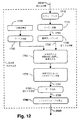
図17は、変形マップD’を形成するために、置換マップDを補間するための補間処理2403Bを示す図である。補間処理2403Bでは、ステップ1910において、図15のステップ2080において格納された置換マップDを受け取る。次のステップ1920では、置換マップDを使用して、置換マップDに最適な線形変換パラメータ(b11,b12,b21,b22,Δx,Δy)の組を判定する。
FIG. 17 is a diagram showing an
暗号フィールド内の任意の点(xij,yij)(尚、このような点のx、yの位置は、文書121内の画素とは対照的に、位置上の変形を受けなかった)は、次の数学的関係に係る置換マップD内の対応する画素(i,j)
次の演算を実行することによって、置換マップを使用して暗号フィールド点を置換し、対応する置換暗号フィールド点座標
![]()
![]()
![]()
![]()
非変形点(xij,yij)に割り当てられた線形変換パラメータ(b11,b12,b21,b22,Δx,Δy)は、次式により、アフィン変換点
![]()
![]()
最適アフィン変換は、置換座標
![]()
![]()
![]()
![]()
最小化の解は、次式により与えられる。
![]()
![]()
次のステップ1930では、次式
その後、次のステップ1940では、最適線形変換を、バイキュービック補間を使用して排除した後、置換マップをDxP×DyP寸法の置換マップに補間する。置換マップが、バイキュービック補間カーネルの隣接部分内に信頼度ゼロを有する画素を有する場合、補間ステップにおいて、複雑化が発生する可能性がある。複雑化が発生した場合、信頼度ゼロを有する画素自体を、画素の信頼値により重み付けされた隣接画素の平均を使用して、推定値で置換する。隣接画素が、正の信頼度を有していない場合、画素値を判定するために、アルゴリズム発展領域は、使用される。次に、補間置換画素は、置換マップ内の置換画素に沿った正の信頼度を有する画素を使用するバイキュービック補間を使用して計算される。
Thereafter, in a
次のステップ1950では、次式により、以前に排除された最適線形変形を補間置換マップD’に再び適用する。
D’(i,j)は、変形マップであり、補間処理2403Bのステップ1950からの出力を形成する。
D '(i, j) is a deformation map and forms the output from
<精位置決めに対する画像ワーピング>
図18は、図17のステップ1950の変形マップD’から精位置決め文書を形成するために使用されたワーピング処理2403Cを示す図である。画像ワーピング処理2403Cでは、入力として、走査文書121と、図12のステップ1790において粗登録処理により生成されたアフィン変換パラメータと、図17のステップ1950の変形マップD’とを使用し、出力として、カラー暗号フィールドに精密に登録された走査文書のワープ形態(精位置決め走査文書と呼ぶ)を使用する。画像ワーピング処理2403Cにおける第1のステップ2601では、変形マップD’を、暗号フィールド内の画素と走査文書121内の画素とを関連付ける関連マップD’cに修正する。この修正は、次式を実行することによって、粗登録ステップ(図12のステップ1790)において判定されたアフィン変換を、変形マップD’に戻り加算することにより行われる。
FIG. 18 is a diagram showing a
その後、更にステップ2601において、暗号フィールド内の画素に対応する走査文書121内の画素は、(a)関連マップD’cを使用して、走査文書121内の各画素に対して、暗号フィールド内の画素位置に対応する走査文書121上のサブ画素位置を判定し、且つ(b)バイキュービック補間を使用して、その位置における走査文書121を補間することにより、識別される。
Thereafter, further in
次のステップ2602では、粗位置決め走査文書121と同一の大きさを有する空画像Ieを形成する。その後、ステップ2603では、上記の空画像Ie内の次の画素を読み取る。次の判断ステップ2304では、Ie内の全ての画素が処理されたか否かが検定される。Ie内の全ての画素が処理された場合、プロセス2403Cは、図4の矢印2423である矢印YESに従って進み、2423(図4を参照)で精位置決め文書を出力する。これに対して、Ie内に未処理の画素が残存する場合、プロセス2403Cは、ステップ2304から「NO」に従って、ステップ2606へ進む。
In the
ステップ2606において、空画像Ie内の考慮中の画素に対して、(x,y)座標は、関連マップD’c内の対応する画素から取り出される。その後、ステップ2607では、この(x,y)座標を使用して、バイキュービック補間により、粗位置決め走査文書121の対応する「真の」画素値を計算する。次のステップ2608では、当該画素に関してワープ(真の)画素値をIe内に書き込むことにより、精位置決め走査文書を形成する。その後、プロセス2403Cは、矢印2609によりステップ2603へ戻る。尚、Ieは、特に、赤強度成分、緑強度成分及び青強度成分のようないくつかの成分を含む。
In
600DPIの精位置決め走査文書Ie及びカラー画像暗号フィールドは、各 ブロックの中央画素をサンプリングすることにより、200DPIに減少する。この減少により、200DPI画素間のいくつかの混色値を有する画素を、回避する。 The 600 DPI fine-position scan document I e and the color image encryption field are reduced to 200 DPI by sampling the central pixel of each block. This reduction avoids pixels that have some color mixing value between 200 DPI pixels.
<精位置決め走査文書の認証>
図19は、改竄検知の一例を示す図である。画素801は、(図2の信号123又は信号124における)精位置決め走査文書812の一部を形成する。4つの画素802は、図8の不正顕示機能付文書705に示す比較可能なオリジナル画素709から変化した。そのため、非認証人物は、図8の文字「EF」を図19の「FE」に変化させるために、2対の画素802を変化させた。
<Authentication of fine positioning scanning document>
FIG. 19 is a diagram illustrating an example of falsification detection.
最初の工程として、矢印813で示すように、精位置決め走査文書812に対して、各画素の輝度値を考慮する閾化モジュール107内で閾値演算が施される。輝度が50%未満の画素は、黒として分類され、残る画素は、白として分類される。オリジナルのソース画像(不図示)として仮定された画像804は、閾値演算の結果として作成される。
As a first step, as indicated by an
文書802の最初の符号化の際に使用された次のカラー画像バージョン暗号フィールド805は、精位置決め走査文書812を被覆するために、十分な領域内に再生される。この再生は、図6のステップ2501からのオリジナル鍵を使用して行われる。オリジナル鍵は、オペレータにより入力されるか、妥当性検証サブシステム127にとって既知であるか、あるいは、作成サブシステム126から、又は他の手段により転送されてもよい。オリジナル鍵は、図6のステップ2508からのソルト値と組み合わされる。
The next color image
次に、選択モジュール109は、閾化画像804内の各画素の値814を使用して選択を制御する。この制御814下において、選択モジュール109は、1つのカラー画像バージョン暗号フィールド又は他のカラー画像バージョン暗号フィールドから画素値816又は画素値815を選択することにより、基準画像807を作成する。この基準画像の作成は、符号化処理において使用された処理と等価の処理である。比較モジュール108内では、基準画像内のこのような各選択画素(画素807等)に対して、選択画素(本例では、画素807)と位置決め走査画像(この場合、画素801)の対応する画素との比較が行われる。画素807の色の副成分及び画素801の色の副成分が、要求された許容範囲内で一致しない場合、画素は、画素の元の状態から改竄されたとして規定される。一構成例によると、画素の色成分のうちの任意の成分が、線形RGBカラー空間内で測定された既定の色に対して通常の補正値25%を越える差異を有する場合、画素は、「一致」状態を満足できなかったとみなされる。各色に対する通常の補正値は、サンプル色のサンプル色パッチ走査により、又は、推定値のみに基づいて判定できる。閾化画像に沿ったこの情報は、新規の認証画像809を構築するために使用される。説明された例において、マゼンダ以外の全ての画素が、閾化画像に係る黒又は白のいずれかである状態で、マゼンダの複数の画素810は、再生される。
The
改竄された画素は、改竄されたポイントにおいて、適切なランダムフィールド(副成分を含む)と偶然にも同一色を有することにより、明らかにされない可能性がある。この状態は、画素が白から黒に変化したにもかかわらず、認証画像内で改変としてフラグされていない場合を示す画素811で示される。上述の構成において、通常、25%までの画素の改変は、検知できない可能性がある。このことは、暗号フィールドが2ビット精度を使用している事実から導出される。検出された画素の75%が、通常、ユーザに対して改変の発生及び特徴を警告するためには十分である。従って、大きな領域(例えば、52ビット鍵内のビット数を超える画素を有する領域)にわたって、検出不可能な不正改変方法を施すことの困難性は、鍵空間の大きさにほぼ比例する。
The altered pixel may not be revealed by accidentally having the same color as the appropriate random field (including subcomponents) at the altered point. This state is indicated by a
最終認証画像809は、通常、オペレータによる試験のためにカラープリンタ上に印刷される。しかしながら、認証画像809は、改変画素の数又は改変画素の稠密領域の存在に基づいた自動解析も施されてもよい。
The
改変画素を明らかにすることが、固有に且つ精密にスケーリングされるため、それを示すように、オリジナル文書708の画素スケールを発生させる。また、改変画素を明らかにすることは、オリジナル文書708を感知できないため、疑わしい文書812及びこれらの改変を明らかにするためのオリジナル鍵のみを必要とする。
Since revealing the modified pixels is inherently and precisely scaled, the pixel scale of the
説明された方法の実質的な利点は、文書812の副次部分の改変を明らかにすることが、文書812の残る部分と無関係であることである。尚、粗位置決め情報及びソルト情報は、高度な冗長を実現するために、空間領域内及び周波数領域内の情報の非常な広域分散に対して十分な信号強度を提供する技法を使用して、文書内に組み込まれる。これは、文書812の残る部分と関連することなく、これらの信号が、文書812の任意の副次部分から回復できることを意味する。上述の構成において、文書の任意の25%の領域からのこれらの信号の回復は、容易に実現できる。尚、精位置決め工程及び認証工程は、局所的処理及び不可視部分に対する高度なロバストさも提供する。従って、システム全体は、柔軟性が高く(特殊な構成を有していない任意の文書の全領域に適用可能である)、且つ部分的な転送又は偶発的文書損害に対してロバストな認証方法を提供する。
A substantial advantage of the described method is that revealing sub-part modifications of
<プリンタドライバにおけるマーキング処理の使用>
改竄防止方法は、マイクロソフトのウィンドウズ(登録商標)ベースコンピュータ等の汎用コンピュータ上のプリンタドライバの一部として内蔵していてもよい。この構成において、プリンタドライバの特性には、改竄防止方法を可能とするためにオペレータが選択できるユーザインタフェースエレメントと、鍵(又はパスワード)の入力が可能な第2のユーザインタフェースエレメントとが設けられている。この構成の一変形例において、プリンタドライバは、応用データを印刷待ち画像に変化させるラスタ化処理を含む。この段階において、印刷待ち画像は、改竄防止方法で説明したように、プリンタドライバにより修正され、生成された画像は、プリンタ装置に送信される。
<Use of marking process in printer driver>
The falsification preventing method may be incorporated as part of a printer driver on a general-purpose computer such as a Microsoft Windows (registered trademark) base computer. In this configuration, the characteristics of the printer driver are provided with a user interface element that can be selected by an operator to enable a falsification prevention method and a second user interface element that allows the input of a key (or password). Yes. In a variation of this configuration, the printer driver includes a rasterization process that changes application data into a print-waiting image. At this stage, the print waiting image is corrected by the printer driver as described in the falsification preventing method, and the generated image is transmitted to the printer apparatus.
第2の変形例において、改竄防止方法は、プリンタ装置内で実行される。この方法は、改竄防止方法が、高周波データを印刷データ内に導入するので、利便性が高い。プリンタへのデータ転送処理、又はプリンタの内部処理が、画像圧縮を採用する場合、この高周波データが存在するため、画像圧縮への効果は少ない。しかしながら、プリンタ装置へのデータ転送後、改竄防止方法が実行された場合、プリンタ装置は、圧縮及び解凍の終了後に、後段の処理において高周波データを加算できる。 In the second modification, the falsification preventing method is executed in the printer apparatus. This method is highly convenient because the falsification preventing method introduces high-frequency data into the print data. When the data transfer processing to the printer or the internal processing of the printer adopts image compression, since this high-frequency data exists, the effect on the image compression is small. However, when the falsification preventing method is executed after data transfer to the printer device, the printer device can add high-frequency data in the subsequent processing after the compression and decompression are completed.
<複合機におけるマーキング及び認証の使用>
改竄防止方法の別の構成では、Canon IR C3200等の複合機の能力として、改竄防止方法を採用する。この構成において、複合機は、セキュリティコピー動作の一部として改竄防止方法を採用可能とするユーザインタフェースエレメントを提供する。プリンタドライバの場合、第2のユーザインタフェースが、鍵入力を可能とする。この実現されたオプションを使用してコピーされた文書が走査され、上述のように、デジタル走査画像がマーキングされ、且つこの生成されたデジタル画像が印刷されることにより、セキュリティコピー動作を提供できる。また、同一の多機能装置又は別の多機能装置は、認証特徴を採用する。この認証特徴も、ユーザインタフェースエレメント及び第2の鍵入力エレメントにより実現できる。このオプションの範囲下においてコピーされた文書は、上述の認証処理が施される。印刷文書は、非改変領域の黒及び白が再現される状態で、マゼンダ(又は他の強調表示色)が明らかにされた改変領域を有する認証処理結果である。
<Use of marking and authentication in MFPs>
In another configuration of the falsification preventing method, the falsification preventing method is adopted as the capability of the multifunction machine such as Canon IR C3200. In this configuration, the multi-function peripheral provides a user interface element that can adopt the falsification preventing method as part of the security copy operation. In the case of a printer driver, the second user interface enables key input. The copied document using this realized option is scanned, as described above, the digital scanned image is marked and the generated digital image is printed to provide a security copy operation. Also, the same multifunction device or another multifunction device employs an authentication feature. This authentication feature can also be realized by the user interface element and the second key input element. Documents copied under the option range are subjected to the above-described authentication processing. The printed document is an authentication processing result having a modified area in which magenta (or other highlighted color) is clarified in a state where black and white of the unmodified area are reproduced.
<スキャナを使用した文書の認証>
改竄防止方法の別の構成では、USBインタフェースを介してマイクロソフトのウィンドウズ(登録商標)を稼動し、且つ改竄防止処理を採用したソフトウェアアプリケーションを稼動している汎用コンピュータに接続されたCanon CanoScan 8000F等のスキャナ装置が使用される。この構成において、ソフトウェアアプリケーションは、TWAINスキャナドライバを使用して、オペレータにより提供された紙文書から文書画像を得る。各文書画像は、改竄防止方法に従って解析される。妥当性検証結果は、オペレータによる検査のために、コンピュータ画面上に表示される。
<Authentication of documents using a scanner>
In another configuration of the falsification prevention method, such as Canon Canon Scan 8000F connected to a general-purpose computer running Microsoft Windows (registered trademark) via a USB interface and running a software application adopting falsification prevention processing, etc. A scanner device is used. In this configuration, the software application uses the TWAIN scanner driver to obtain the document image from the paper document provided by the operator. Each document image is analyzed according to a falsification preventing method. The validation result is displayed on the computer screen for inspection by the operator.
<枚葉紙スキャナを使用した大容量文書の認証>
改竄防止方法の別の構成では、Canon DR−5080C等のデスクトップ型高速枚葉スキャナが使用される。この構成において、大容量文書は、オペレータが介入することなく走査される。妥当性検証処理が、走査処理と同期して使用されることにより、改変された文書は、発見される。この構成において、妥当性検証処理の結果であるデジタル画像は、改変画素の閾値を越える画素を含む複数の小さなパッチに対して試験される。パッチの大きさ及び閾値は、オペレータによる設定が可能である。また、文書の異なる領域における異なる閾値及びパッチを設定すること、並びに文書が形態認識システムにより識別されたこれらの領域を有することも可能である。
<Authentication of large documents using a sheet scanner>
In another configuration of the falsification preventing method, a desktop high-speed sheet-fed scanner such as Canon DR-5080C is used. In this configuration, large documents are scanned without operator intervention. The modified document is found by using the validation process in synchronization with the scanning process. In this configuration, the digital image resulting from the validation process is tested against a plurality of small patches that include pixels that exceed the modified pixel threshold. The size and threshold value of the patch can be set by the operator. It is also possible to set different thresholds and patches in different regions of the document and to have these regions identified by the form recognition system.
[産業上の利用可能性]
上述したように、上記の構成が、文書処理産業に適用できることは、明らかである。
[Industrial applicability]
As described above, it is obvious that the above configuration can be applied to the document processing industry.
先の説明は、本発明のいくつかの実施の形態のみを説明したが、本発明の趣旨の範囲を逸脱せずに、本発明の変形及び/又は変更を行うことができる。実施の形態は、例証するものであって、限定するものではない。 Although the foregoing description has described only some embodiments of the present invention, variations and / or modifications of the present invention can be made without departing from the scope of the present invention. The embodiments are illustrative and not limiting.
Claims (19)
(a)分解手段により、記録されるべきN値レベル画像に関して、前記画像の少なくとも1つの画素をN個の可能な値を有する主成分に分解する工程と、
(b)選択手段により、少なくとも1つの所定のパターンのうちの、前記主成分の値に対応する所定のパターンからパターン要素を選択する工程であって、該所定のパターンはそのパターン要素がそれぞれ位置に対応づけられたシーケンスであり、前記画像内の前記少なくとも1つの画素の位置に対応する該パターン要素を選択する工程と、
(c)形成手段により、前記少なくとも1つの画素に対して選択された前記パターン要素を転送媒体上に記録して不正顕示機能付文書を形成する工程と、
(d)抽出手段により、前記少なくとも1つの画素に対して検索パターン要素を不正顕示機能付文書から抽出する工程と、
(e)判定手段により、(di)前記検索パターン要素から抽出された主成分と、(dii)前記不正顕示機能付文書上の前記少なくとも1つの画素の位置と、に対応するパターン要素を判定する工程と、
(f)比較手段により、前記検索パターン要素と判定された前記パターン要素とを比較する工程と
を有することを特徴とする方法。 A method by means of a computer system for processing a document with fraud revealing function,
(A) a step of decomposing at least one pixel of said image into principal components having N possible values with respect to the N-value level image to be recorded by a decomposing means ;
(B) a step of selecting a pattern element from a predetermined pattern corresponding to the value of the principal component among at least one predetermined pattern by a selection means , wherein the pattern element is located at each position Selecting the pattern element corresponding to the position of the at least one pixel in the image ;
(C) optionally forming means and forming the at least one unauthorized revealed features with document records the pattern elements on the transfer medium selected for the pixel,
(D) by extraction means, a step of extracting from the at least one unauthorized revealed features with document search pattern elements for the pixels,
The (e) determining means determines (di) the search and principal components extracted from the pattern elements, (dii) corresponding pattern element and position, of the at least one pixel on the fraud revealed function with Article Process,
(F) Comparing the pattern element determined to be the search pattern element with a comparison means .
前記抽出する工程においては、前記不正顕示機能付文書を走査して、該不正顕示機能付文書上に印刷された前記検索パターン要素を抽出する
ことを特徴とする請求項1に記載の方法。 In the forming step , the pattern element is recorded on the transfer medium by printing the pattern element on the transfer medium;
2. The method according to claim 1, wherein, in the extracting step, the search pattern element printed on the document with the fraud revealing function is extracted by scanning the document with the fraud revealing function .
(ga)前記N個の暗号フィールドのそれぞれについて、パターン要素を生成する工程と、
(gb)前記N個の暗号フィールドの各パターン要素を、各暗号フィールドについて、それぞれ前記N値レベル画像の各画素位置に対応づけて、前記暗号フィールドを位置決めする工程と、
(gc)前記主成分値に対応する前記暗号フィールドを選択する工程と、
(gd)前記選択された暗号フィールドから、前記画像内の前記少なくとも1つの画素の前記位置に対応する前記パターン要素を選択する工程とを有し、
(i)前記記録する工程の後であって前記判定する工程の前に、前記方法が、
(ia)前記N個の暗号フィールドを生成する工程と、
(ib)記録された前記画素の前記位置が設定可能となるように、前記記録されるべきN値レベル画像を使用して、前記暗号フィールドを位置決めする工程とをさらに有することを特徴とする請求項4に記載の方法。 (G) The step (a) of decomposing includes
(Ga) for each of the N encrypted field, generating a pattern element,
(Gb) associating each pattern element of the N encryption fields with each pixel position of the N-level image for each encryption field, and positioning the encryption field;
(Gc) a step of selecting the encryption field corresponding to the main component values,
(Gd) selecting from the selected cipher field the pattern element corresponding to the position of the at least one pixel in the image;
(I) after the recording step and before the determining step, the method comprises:
(Ia) and generating said N encrypted field,
(Ib) further comprising positioning the cipher field using the N-value level image to be recorded so that the position of the recorded pixel can be set. Item 5. The method according to Item 4 .
(a)分解手段により、記録されるべきN値レベル画像に関して、前記画像の少なくとも1つの画素を、N個の可能な値を有する主成分と、並びに(ai)前記主成分及び(aii)前記画像内の前記少なくとも1つの画素の位置に依存する、対応するランダム化副成分と、に分解する工程と、
(b)形成手段により、前記少なくとも1つの画素に対する前記主成分及び前記ランダム化副成分を転送媒体上に記録して不正顕示機能付文書を形成する工程と、
(c)抽出手段により、前記少なくとも1つの画素に対する前記主成分を不正顕示機能付文書から抽出する工程と、
(d)判定手段により、(di)前記抽出主成分と、(dii)前記不正顕示機能付文書上の前記少なくとも1つの画素の位置とに依存する、前記対応するランダム化副成分を判定する工程と、
(e)測定手段により、前記少なくとも1つの画素について印刷された前記ランダム化副成分を前記不正顕示機能付文書から測定する工程と、
(f)宣言手段により、測定された前記印刷ランダム化副成分が判定された前記ランダム化副成分と一致しない場合、前記不正顕示機能付文書の前記画素が改竄されたと宣言する工程と
を有することを特徴とする方法。 A method by means of a computer system for processing a document with fraud revealing function,
The (a) separation means, with respect to N value level image to be recorded, at least one pixel of the image, a main component with N possible values, and (ai) of the main component and (aii) the depends on the position of the at least one pixel in the image, the corresponding randomized subcomponent, and decomposing the,
The (b) forming means and forming a fraud revealed features with documents to record the said main component and said randomization subcomponent with respect to at least one pixel on the transfer medium,
(C) extracting the principal component for the at least one pixel from the document with an unauthorized revealing function by an extraction unit ;
(D) the determining means, (di) and the extraction main component, (dii) wherein dependent on the position of the at least one pixel on the fraud revealed function with the document, step of determining said corresponding randomized subcomponent When,
The (e) measuring means, and measuring the at least one of said randomized subcomponent printed with the pixel from the unauthorized manifestation function with the document,
And (f) declaring that the pixel of the document with the fraud revealing function has been tampered with when the measured printing randomized subcomponent does not match the determined randomized subcomponent by the declaring means. A method characterized by.
(a)抽出手段により、検索パターン要素を、不正顕示機能付文書内の位置から抽出する工程と、
(b)選択手段により、少なくとも1つの所定のパターンのうちの、前記検索パターン要素の特性に対応する所定のパターンからパターン要素を選択する工程であって、該所定のパターンはそのパターン要素がそれぞれ位置に対応づけられたシーケンスであり、前記位置に対応する該パターン要素を選択する工程と、
(c)比較手段により、前記検索パターン要素と選択された前記パターン要素とを比較する工程と
を有することを特徴とする方法。 A method by each means of a computer system for validating a document with a fraud revealing function,
(A) a step of extracting a search pattern element from a position in a document with an unauthorized revealing function by an extraction means ;
(B) a step of selecting a pattern element from a predetermined pattern corresponding to the characteristic of the search pattern element , out of at least one predetermined pattern by the selection means , and each of the predetermined patterns is a pattern element A sequence associated with a position, selecting the pattern element corresponding to the position;
(C) Comparing the search pattern element with the selected pattern element by comparison means .
(e)生成手段により、前記N個の暗号フィールドのそれぞれについて、パターン要素を生成する工程と、
(f)位置決め手段により、前記検索パターン要素の前記位置と暗号フィールド位置との関連付けが可能となるように、前記N個の暗号フィールドの各パターン要素を、各暗号フィールドについて、それぞれ前記記録された画像の各画素位置に対応づけて、前記暗号フィールドを位置決めする工程と
をさらに有することを特徴とする請求項13に記載の方法。 Before being selected
The (e) generating means, for each of the N encrypted field, generating a pattern element,
The (f) positioning means such that said association between said position and the encryption field position of the search pattern elements is possible, for each pattern element of the N encrypted fields, for each encryption field, which is the recording, respectively 14. The method of claim 13 , further comprising the step of positioning the encryption field in association with each pixel location of the image.
(a)抽出手段により、不正顕示機能付文書に含まれる少なくとも1つの記録画素に対して、N個の可能な値を有する主成分を前記不正顕示機能付文書から抽出する工程と、
(b)判定手段により、少なくとも1つの所定のパターンのうちの、前記抽出主成分に対応する所定のパターンからパターン要素を選択し、該パターン要素に対応して予め定められたランダム化副成分を判定する工程であって、該所定のパターンはそのパターン要素がそれぞれ位置に対応づけられたシーケンスであり、前記少なくとも1つの記録画素の位置に対応する該パターン要素に対応して予め定められた対応するランダム化副成分を判定する工程と、
(c)測定手段により、前記少なくとも1つの画素に対応して前記不正顕示機能付文書上に記録されているランダム化副成分を、前記不正顕示機能付文書から測定する工程と、
(d)比較手段により、測定された前記ランダム化副成分と判定された前記ランダム化副成分とを比較する工程と
を有することを特徴とする方法。 A method by each means of a computer system for validating a document with a fraud revealing function,
By (a) extracting means, a step of extracting at least with respect to one recording pixel, the main component having N possible values from the unauthorized manifestation function with documents included in the unauthorized revelation function with the document,
(B) The determination unit selects a pattern element from a predetermined pattern corresponding to the extracted main component from at least one predetermined pattern, and selects a randomized subcomponent determined in advance corresponding to the pattern element. The predetermined pattern is a sequence in which each pattern element is associated with a position, and a predetermined correspondence corresponding to the pattern element corresponding to the position of the at least one recording pixel Determining a randomized sub-component to perform;
The (c) measuring means, and measuring from said at least one randomized sub ingredient corresponding to a pixel is recorded on the unauthorized revealed function with the document, the unauthorized revelation function with the document,
The (d) comparing means, method characterized by a step of comparing the is determined that said measured randomized subcomponent said randomized subcomponent.
Applications Claiming Priority (1)
| Application Number | Priority Date | Filing Date | Title |
|---|---|---|---|
| AU2004902153A AU2004902153A0 (en) | 2004-04-21 | Secure Printed Documents |
Publications (2)
| Publication Number | Publication Date |
|---|---|
| JP2006014280A JP2006014280A (en) | 2006-01-12 |
| JP4137084B2 true JP4137084B2 (en) | 2008-08-20 |
Family
ID=35186294
Family Applications (1)
| Application Number | Title | Priority Date | Filing Date |
|---|---|---|---|
| JP2005123918A Expired - Fee Related JP4137084B2 (en) | 2004-04-21 | 2005-04-21 | Method for processing documents with fraud revealing function and method for validating documents with fraud revealing function |
Country Status (2)
| Country | Link |
|---|---|
| US (1) | US7711140B2 (en) |
| JP (1) | JP4137084B2 (en) |
Families Citing this family (43)
| Publication number | Priority date | Publication date | Assignee | Title |
|---|---|---|---|---|
| US7644282B2 (en) | 1998-05-28 | 2010-01-05 | Verance Corporation | Pre-processed information embedding system |
| US6737957B1 (en) | 2000-02-16 | 2004-05-18 | Verance Corporation | Remote control signaling using audio watermarks |
| CA2499967A1 (en) | 2002-10-15 | 2004-04-29 | Verance Corporation | Media monitoring, management and information system |
| US20060239501A1 (en) | 2005-04-26 | 2006-10-26 | Verance Corporation | Security enhancements of digital watermarks for multi-media content |
| US7532768B2 (en) * | 2003-11-04 | 2009-05-12 | Canon Kabushiki Kaisha | Method of estimating an affine relation between images |
| US20060202468A1 (en) * | 2005-02-22 | 2006-09-14 | Verify First Technologies, Inc. | Security document having integrated copy-void and validation security features |
| US8020004B2 (en) | 2005-07-01 | 2011-09-13 | Verance Corporation | Forensic marking using a common customization function |
| US8781967B2 (en) | 2005-07-07 | 2014-07-15 | Verance Corporation | Watermarking in an encrypted domain |
| EP1744287B1 (en) * | 2005-07-13 | 2008-04-30 | Neopost S.A. | Methods and systems for signing physical documents and for authenticating signatures on physical documents |
| US20080091954A1 (en) * | 2006-10-17 | 2008-04-17 | Morris Daniel R | Method and system for facilitating printed page authentication, unique code generation and content integrity verification of documents |
| AU2007203062B2 (en) * | 2007-06-29 | 2010-05-13 | Canon Kabushiki Kaisha | Alpha-masked image matching |
| US8068674B2 (en) * | 2007-09-04 | 2011-11-29 | Evolution Robotics Retail, Inc. | UPC substitution fraud prevention |
| JP2009290560A (en) | 2008-05-29 | 2009-12-10 | Ricoh Co Ltd | Image forming apparatus, print processing method, program, and recording medium |
| JP5287072B2 (en) * | 2008-09-17 | 2013-09-11 | 株式会社リコー | Image processing apparatus, image processing method, and image processing program |
| AU2008255227A1 (en) * | 2008-12-10 | 2010-06-24 | Canon Kabushiki Kaisha | Document security method |
| US8531401B2 (en) | 2009-08-13 | 2013-09-10 | Hewlett-Packard Development Company, L.P. | Computer accessory device |
| US20110066504A1 (en) * | 2009-09-17 | 2011-03-17 | Ehud Chatow | System for providing promotion information |
| US8430301B2 (en) * | 2009-11-23 | 2013-04-30 | Konica Minolta Laboratory U.S.A., Inc. | Document authentication using hierarchical barcode stamps to detect alterations of barcode |
| US8488007B2 (en) * | 2010-01-19 | 2013-07-16 | Sony Corporation | Method to estimate segmented motion |
| US8285079B2 (en) * | 2010-03-19 | 2012-10-09 | Sony Corporation | Method for highly accurate estimation of motion using phase correlation |
| US9607131B2 (en) | 2010-09-16 | 2017-03-28 | Verance Corporation | Secure and efficient content screening in a networked environment |
| US20150028579A1 (en) * | 2011-05-01 | 2015-01-29 | Yann Boutant | Method of unitary authentication of a hardware object comprising visual cryptography and material signature |
| US8615104B2 (en) | 2011-11-03 | 2013-12-24 | Verance Corporation | Watermark extraction based on tentative watermarks |
| US8682026B2 (en) * | 2011-11-03 | 2014-03-25 | Verance Corporation | Efficient extraction of embedded watermarks in the presence of host content distortions |
| US8923548B2 (en) | 2011-11-03 | 2014-12-30 | Verance Corporation | Extraction of embedded watermarks from a host content using a plurality of tentative watermarks |
| US8745403B2 (en) | 2011-11-23 | 2014-06-03 | Verance Corporation | Enhanced content management based on watermark extraction records |
| US9323902B2 (en) | 2011-12-13 | 2016-04-26 | Verance Corporation | Conditional access using embedded watermarks |
| US10359972B2 (en) | 2012-08-31 | 2019-07-23 | Sandisk Technologies Llc | Systems, methods, and interfaces for adaptive persistence |
| US9116812B2 (en) | 2012-01-27 | 2015-08-25 | Intelligent Intellectual Property Holdings 2 Llc | Systems and methods for a de-duplication cache |
| US10339056B2 (en) | 2012-07-03 | 2019-07-02 | Sandisk Technologies Llc | Systems, methods and apparatus for cache transfers |
| US9571606B2 (en) | 2012-08-31 | 2017-02-14 | Verance Corporation | Social media viewing system |
| US8869222B2 (en) | 2012-09-13 | 2014-10-21 | Verance Corporation | Second screen content |
| US9106964B2 (en) | 2012-09-13 | 2015-08-11 | Verance Corporation | Enhanced content distribution using advertisements |
| WO2014153199A1 (en) | 2013-03-14 | 2014-09-25 | Verance Corporation | Transactional video marking system |
| US9251549B2 (en) | 2013-07-23 | 2016-02-02 | Verance Corporation | Watermark extractor enhancements based on payload ranking |
| US9208334B2 (en) | 2013-10-25 | 2015-12-08 | Verance Corporation | Content management using multiple abstraction layers |
| WO2015138798A1 (en) | 2014-03-13 | 2015-09-17 | Verance Corporation | Interactive content acquisition using embedded codes |
| EP3248360B1 (en) | 2015-01-19 | 2020-05-06 | Inauth, Inc. | Systems and methods for trusted path secure communication |
| AU2015202937A1 (en) * | 2015-05-29 | 2016-12-15 | Canon Kabushiki Kaisha | Systems and methods for registration of images |
| US10931455B2 (en) * | 2015-09-28 | 2021-02-23 | EyeVerify Inc. | Secure image pipeline |
| US10534971B2 (en) | 2016-10-14 | 2020-01-14 | ID Metrics Group Incorporated | Tamper detection for identification documents |
| CN107229953B (en) * | 2017-06-06 | 2020-12-25 | 西南石油大学 | Broken document splicing method based on DFS and improved center clustering method |
| JP2021170230A (en) * | 2020-04-15 | 2021-10-28 | Dgshape株式会社 | Cutting machine and correction method for position coordinates of storage part, and computer program |
Family Cites Families (22)
| Publication number | Priority date | Publication date | Assignee | Title |
|---|---|---|---|---|
| IL104520A0 (en) * | 1993-01-26 | 1993-05-13 | Be Eri Printers | Monetary instrument and method for verification thereof |
| US5291243A (en) * | 1993-02-05 | 1994-03-01 | Xerox Corporation | System for electronically printing plural-color tamper-resistant documents |
| US6366696B1 (en) * | 1996-12-20 | 2002-04-02 | Ncr Corporation | Visual bar code recognition method |
| US5875249A (en) * | 1997-01-08 | 1999-02-23 | International Business Machines Corporation | Invisible image watermark for image verification |
| US6285775B1 (en) * | 1998-10-01 | 2001-09-04 | The Trustees Of The University Of Princeton | Watermarking scheme for image authentication |
| US6167147A (en) * | 1998-10-26 | 2000-12-26 | The Standard Register Company | Security document including pseudo-random image and method of making the same |
| DE69923781T2 (en) * | 1998-11-19 | 2005-07-07 | Digimarc Corp., Lake Oswego | PRINTING AND VERIFICATION OF SELF-CHECKING SAFETY DOCUMENTS |
| US6741737B1 (en) * | 1999-03-18 | 2004-05-25 | Choicepoint Asset Company | System and method for the secure data entry from document images |
| US6457651B2 (en) * | 1999-10-01 | 2002-10-01 | Xerox Corporation | Dual mode, dual information, document bar coding and reading system |
| US20050129270A1 (en) * | 2000-08-30 | 2005-06-16 | Ravi Prakash | Method and system for applying a watermark |
| US6694041B1 (en) * | 2000-10-11 | 2004-02-17 | Digimarc Corporation | Halftone watermarking and related applications |
| AUPR105000A0 (en) * | 2000-10-27 | 2000-11-23 | Canon Kabushiki Kaisha | Method for generating and detecting marks |
| US8543823B2 (en) * | 2001-04-30 | 2013-09-24 | Digimarc Corporation | Digital watermarking for identification documents |
| US7072488B2 (en) * | 2001-07-11 | 2006-07-04 | Canon Kabushiki Kaisha | Data processing method and apparatus |
| AUPR970601A0 (en) * | 2001-12-21 | 2002-01-24 | Canon Kabushiki Kaisha | Encoding information in a watermark |
| US7085399B2 (en) * | 2002-06-18 | 2006-08-01 | Oki Electric Industry Co., Ltd. | Watermark information embedding device and watermark information detection device |
| JP2004023565A (en) * | 2002-06-18 | 2004-01-22 | Canon Inc | Electronic watermark burying apparatus, electronic watermark extracting apparatuses, and method thereof |
| US20040038756A1 (en) * | 2002-08-23 | 2004-02-26 | Art Brophy | Ball-tossing apparatus |
| AU2002951815A0 (en) * | 2002-10-03 | 2002-10-24 | Canon Kabushiki Kaisha | Mark embedding and detection using projective transforms |
| US7104709B1 (en) * | 2003-06-23 | 2006-09-12 | Rosetta Technologies Corporation | Document printing process |
| US7245740B2 (en) * | 2003-07-01 | 2007-07-17 | Oki Electric Industry Co., Ltd. | Electronic watermark embedding device, electronic watermark detection device, electronic watermark embedding method, and electronic watermark detection method |
| KR100506661B1 (en) * | 2003-10-02 | 2005-08-10 | 한국전자통신연구원 | The method for embedding Watermarks on the lowest wavelet subband and the extracting method |
-
2005
- 2005-04-19 US US11/108,712 patent/US7711140B2/en not_active Expired - Fee Related
- 2005-04-21 JP JP2005123918A patent/JP4137084B2/en not_active Expired - Fee Related
Also Published As
| Publication number | Publication date |
|---|---|
| US7711140B2 (en) | 2010-05-04 |
| JP2006014280A (en) | 2006-01-12 |
| US20050242568A1 (en) | 2005-11-03 |
Similar Documents
| Publication | Publication Date | Title |
|---|---|---|
| JP4137084B2 (en) | Method for processing documents with fraud revealing function and method for validating documents with fraud revealing function | |
| EP1485863B1 (en) | Authenticating printed objects using digital watermarks associated with multidimensional quality metrics | |
| JP4965278B2 (en) | An improved technique for detecting, analyzing and using visible authentication patterns | |
| US7027614B2 (en) | Hiding information to reduce or offset perceptible artifacts | |
| EP1930857B1 (en) | Image processing apparatus and image processing method, program, and storage medium | |
| WO2018076409A1 (en) | Method for realizing two dimensional code copy prevention and realization system thereof | |
| JP4187749B2 (en) | Halftone watermarking and related applications | |
| US8736908B2 (en) | Printing and authentication of a security document on a substrate utilizing unique substrate properties | |
| CN107918791B (en) | Two-dimensional code generating and decoding method and device in two-dimensional code copying process | |
| US8595503B2 (en) | Method of self-authenticating a document while preserving critical content in authentication data | |
| JP2004007442A (en) | Information processing method and device, computer program and computer readable storage medium | |
| JP4426617B2 (en) | Document falsification detection method using encoded dots | |
| Mayer et al. | Fundamentals and applications of hardcopy communication | |
| JP2007036317A (en) | Image processing method, image processor and truth decision method | |
| AU2005201622B2 (en) | Secure recorded documents | |
| JP5850370B2 (en) | Printed material production method, printed material and authenticity determination method | |
| Thongkor et al. | An image authentication method for paper checks | |
| JP2008289093A (en) | Method of certifying copy, and image processing system and apparatus related thereto | |
| WO2019095172A1 (en) | Qr code generating and decoding method and apparatus in qr code copying process | |
| Kasprzak et al. | Printed steganography applied for the authentication of identity photos in face verification | |
| Iqbal | High capacity analog channels for smart documents |
Legal Events
| Date | Code | Title | Description |
|---|---|---|---|
| A131 | Notification of reasons for refusal |
Free format text: JAPANESE INTERMEDIATE CODE: A131 Effective date: 20080205 |
|
| A521 | Request for written amendment filed |
Free format text: JAPANESE INTERMEDIATE CODE: A523 Effective date: 20080407 |
|
| TRDD | Decision of grant or rejection written | ||
| A01 | Written decision to grant a patent or to grant a registration (utility model) |
Free format text: JAPANESE INTERMEDIATE CODE: A01 Effective date: 20080507 |
|
| A01 | Written decision to grant a patent or to grant a registration (utility model) |
Free format text: JAPANESE INTERMEDIATE CODE: A01 |
|
| A61 | First payment of annual fees (during grant procedure) |
Free format text: JAPANESE INTERMEDIATE CODE: A61 Effective date: 20080603 |
|
| R150 | Certificate of patent or registration of utility model |
Free format text: JAPANESE INTERMEDIATE CODE: R150 |
|
| FPAY | Renewal fee payment (event date is renewal date of database) |
Free format text: PAYMENT UNTIL: 20110613 Year of fee payment: 3 |
|
| FPAY | Renewal fee payment (event date is renewal date of database) |
Free format text: PAYMENT UNTIL: 20120613 Year of fee payment: 4 |
|
| FPAY | Renewal fee payment (event date is renewal date of database) |
Free format text: PAYMENT UNTIL: 20120613 Year of fee payment: 4 |
|
| FPAY | Renewal fee payment (event date is renewal date of database) |
Free format text: PAYMENT UNTIL: 20130613 Year of fee payment: 5 |
|
| LAPS | Cancellation because of no payment of annual fees |