JP4143314B2 - Image processing method, apparatus for realizing the same, and printer driver - Google Patents
Image processing method, apparatus for realizing the same, and printer driver Download PDFInfo
- Publication number
- JP4143314B2 JP4143314B2 JP2002072555A JP2002072555A JP4143314B2 JP 4143314 B2 JP4143314 B2 JP 4143314B2 JP 2002072555 A JP2002072555 A JP 2002072555A JP 2002072555 A JP2002072555 A JP 2002072555A JP 4143314 B2 JP4143314 B2 JP 4143314B2
- Authority
- JP
- Japan
- Prior art keywords
- image
- output
- print area
- aspect ratio
- scaling
- Prior art date
- Legal status (The legal status is an assumption and is not a legal conclusion. Google has not performed a legal analysis and makes no representation as to the accuracy of the status listed.)
- Expired - Lifetime
Links
- 238000003672 processing method Methods 0.000 title claims description 15
- 238000000034 method Methods 0.000 claims description 48
- 230000007423 decrease Effects 0.000 claims 1
- 230000006870 function Effects 0.000 description 34
- 238000010586 diagram Methods 0.000 description 24
- 230000014509 gene expression Effects 0.000 description 7
- 238000006243 chemical reaction Methods 0.000 description 4
- 238000004891 communication Methods 0.000 description 4
- 238000004364 calculation method Methods 0.000 description 3
- 230000003287 optical effect Effects 0.000 description 2
- 238000013139 quantization Methods 0.000 description 2
- 239000003086 colorant Substances 0.000 description 1
- 238000013500 data storage Methods 0.000 description 1
- 230000000694 effects Effects 0.000 description 1
- 238000011946 reduction process Methods 0.000 description 1
Images


Classifications
-
- H—ELECTRICITY
- H04—ELECTRIC COMMUNICATION TECHNIQUE
- H04N—PICTORIAL COMMUNICATION, e.g. TELEVISION
- H04N1/00—Scanning, transmission or reproduction of documents or the like, e.g. facsimile transmission; Details thereof
- H04N1/387—Composing, repositioning or otherwise geometrically modifying originals
- H04N1/3877—Image rotation
-
- G—PHYSICS
- G06—COMPUTING; CALCULATING OR COUNTING
- G06T—IMAGE DATA PROCESSING OR GENERATION, IN GENERAL
- G06T3/00—Geometric image transformations in the plane of the image
- G06T3/40—Scaling of whole images or parts thereof, e.g. expanding or contracting
-
- H—ELECTRICITY
- H04—ELECTRIC COMMUNICATION TECHNIQUE
- H04N—PICTORIAL COMMUNICATION, e.g. TELEVISION
- H04N1/00—Scanning, transmission or reproduction of documents or the like, e.g. facsimile transmission; Details thereof
- H04N1/387—Composing, repositioning or otherwise geometrically modifying originals
- H04N1/3872—Repositioning or masking
- H04N1/3873—Repositioning or masking defined only by a limited number of coordinate points or parameters, e.g. corners, centre; for trimming
- H04N1/3875—Repositioning or masking defined only by a limited number of coordinate points or parameters, e.g. corners, centre; for trimming combined with enlarging or reducing
Landscapes
- Engineering & Computer Science (AREA)
- Multimedia (AREA)
- Signal Processing (AREA)
- Physics & Mathematics (AREA)
- General Physics & Mathematics (AREA)
- Theoretical Computer Science (AREA)
- Record Information Processing For Printing (AREA)
- Editing Of Facsimile Originals (AREA)
- Accessory Devices And Overall Control Thereof (AREA)
Description
【0001】
【産業上の利用分野】
本発明は画像処理方法及びそれを実現する装置及びプリンタドライバに関し、特に、印刷媒体の印刷領域すべてを利用し、かつ極力画像を切り取らず画像の中央部分を印刷したい場合の画像処理方法及びそれを実現する装置及びプリンタドライバに関するものである。
【0002】
【従来技術】
従来、例えば、パーソナルコンピュータ上で合成される画像をプリンタにより出力する場合に、プリンタドライバなどで画像を印刷領域に収まるようなフィットページ印刷の機能がある。又、画像を印刷媒体の中央に配置する機能であるセンタリング機能がある。
【0003】
【発明が解決しようとする課題】
しかしながら、印刷領域一杯に画像を印刷させようとする要請、特に、近年のプリンタにおいてはフチなし印刷機能を有するものが主流になってきて、印刷媒体に余白なく印刷する技術が望まれている。その手法を従来のプリンタドライバの機能のままで実現しようとすると、第1にユーザが画像データそのものを印刷媒体と同じアスペクト比に切り取り、フチなしの印刷領域にフィットさせて印刷する方法が考えられる。又、第2にユーザが拡大縮小機能を利用して、印刷媒体を大きくはみ出すように拡大処理を行い印刷する方法も考えられる。又は、第3にアプリケーションがプリンタドライバと連携をとり自動的に印刷媒体に余白なく印刷できるように画像を拡大する手法も考えられる。
【0004】
しかし、上記従来技術の延長である第1及び第2の手法では、ユーザによる手作業が大部分を占めてしまうため専門知識を必要とする上に、処理時間が遅くなってしまう。又、第3の手法では、専用のアプリケーションがない環境では簡単に印刷ができないという問題が起こる。
【0005】
本発明は、前記従来の問題点に鑑み、ユーザによる簡単な操作で出力領域一杯になるような出力処理を実現する画像処理方法及びそれを実現する装置及びプリンタドライバを提供する。
【0008】
【課題を解決するための手段】
上記課題を解決するために、本発明の画像処理方法は、印刷媒体に余白なく所望の画像を出力する画像処理方法であって、前記印刷媒体より大きい印刷領域を設定し、所望の画像の出力領域が該印刷領域を包含する大きさに前記所望の画像を縦横同じ率で変倍する画像変倍工程と、該画像変倍工程で変倍した画像の前記出力領域が前記印刷領域からはみ出す方向にはみ出し量が両側で同等となる位置に、画像出力位置を移動する出力位置移動工程と、前記変倍して出力位置を移動した画像の前記出力領域が前記印刷領域をはみ出す場合に、該はみ出す部分の出力を禁止する出力禁止工程とを有することを特徴とする。
【0009】
ここで、前記画像変倍工程では、縦横の少なくともいずれかが前記印刷領域に一致するように変倍する。また、前記画像変倍工程では、前記印刷領域のアスペクト比と所望の画像のアスペクト比との比較に基づいて変倍率を決定し、画像の拡大の場合には、前記印刷領域のアスペクト比の方が大きい場合には画像の縦が前記印刷領域に一致するように変倍し、前記印刷領域のアスペクト比の方が小さい場合には画像の横が前記印刷領域に一致するように変倍する。また、前記画像変倍工程に先立って、変倍した画像が前記印刷領域からはみ出す部分が少なくなるように画像を90°回転する画像回転工程を更に有する。また、前記画像回転工程では、印刷領域のアスペクト比と所望の画像のアスペクト比とに基づいて回転するか否かを決定し、前記アスペクト比の1との大小が共に同じ場合には回転を行わず、前記アスペクト比の1との大小が逆の場合には回転を行う。また、前記いずれの工程もプリンタドライバが実行する。
【0012】
又、本発明の画像処理装置は、画像出力装置が印刷媒体に出力する画像データを作成する画像処理装置であって、前記画像出力装置が、前記印刷媒体より大きい印刷領域を設定し、所望の画像の出力領域が該印刷領域を包含する大きさに前記所望の画像を縦横同じ率で変倍した画像データを生成する画像変倍手段と、該画像変倍手段で変倍した画像の前記出力領域が前記印刷領域からはみ出す方向にはみ出し量が両側で同等となる位置に、画像出力位置が移動する画像データを生成する出力位置移動手段と、前記変倍して出力位置を移動した画像の前記出力領域が前記印刷領域をはみ出して出力されないように、該はみ出す部分の出力を禁止する出力禁止手段とを有することを特徴とする。
【0013】
ここで、前記画像変倍手段では、縦横の少なくともいずれかが前記印刷領域に一致するように変倍する。また、前記画像変倍手段は、前記印刷領域のアスペクト比と所望の画像のアスペクト比との比較に基づいて変倍率を決定し、画像の拡大の場合には、前記印刷領域のアスペクト比の方が大きい場合には画像の縦が前記印刷領域に一致するように変倍し、前記印刷領域のアスペクト比の方が小さい場合には画像の横が前記印刷領域に一致するように変倍する。また、変倍された画像が前記印刷領域からはみ出す部分が少なくなるように画像を90°回転した画像データを生成する画像回転手段を更に有する。また、前記画像回転手段は、印刷領域のアスペクト比と所望の画像のアスペクト比とに基づいて回転するか否かを決定し、前記アスペクト比の1との大小が共に同じ場合には回転を行わず、前記アスペクト比の1との大小が逆の場合には回転を行う。また、前記いずれの手段もプリンタドライバに含まれる。
【0016】
又、本発明のプリンタドライバは、画像出力装置が印刷媒体に出力する画像データを作成するプリンタドライバであって、前記画像出力装置が、前記印刷媒体より大きい印刷領域を設定し、所望の画像の出力領域が該印刷領域を包含する大きさに前記所望の画像を縦横同じ率で変倍した画像データを生成する画像変倍モジュールと、該画像変倍モジュールで変倍した画像の前記出力領域が前記印刷領域からはみ出す方向にはみ出し量が両側で同等となる位置に、画像出力位置が移動する画像データを生成する出力位置移動モジュールと、前記変倍して出力位置を移動した画像の前記出力領域が前記印刷領域をはみ出して出力されないように、該はみ出す部分の出力を禁止する出力禁止モジュールとを有することを特徴とする。
【0017】
ここで、前記画像変倍モジュールでは、縦横の少なくともいずれかが前記印刷領域に一致するように変倍する。また、前記画像変倍モジュールは、前記印刷領域のアスペクト比と所望の画像のアスペクト比との比較に基づいて変倍率を決定し、画像の拡大の場合には、前記印刷領域のアスペクト比の方が大きい場合には画像の縦が前記印刷領域に一致するように変倍し、前記印刷領域のアスペクト比の方が小さい場合には画像の横が前記印刷領域に一致するように変倍する前記変倍した画像が前記印刷領域からはみ出す部分が少なくなるように画像を90°回転した画像データを生成する画像回転モジュールを更に有する。また、前記画像回転モジュールは、印刷領域のアスペクト比と所望の画像のアスペクト比とに基づいて回転するか否かを決定し、前記アスペクト比の1との大小が共に同じ場合には回転を行わず、前記アスペクト比の1との大小が逆の場合には回転を行う。
【0018】
又、本発明は、プリンタドライバをコンピュータ読出し可能に記憶する記憶媒体をも提供する。
【0019】
【発明の実施の形態】
以下、添付図面を参照して本発明の実施形態について説明する。
【0020】
<本実施形態の画像処理システムの構成例>
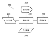
図1は、本発明の一実施形態を示す画像処理システムの構成を示すブロック図である。図1では、ローカルな画像処理システム200として示してある。
【0021】
出力装置205は、例えばカラープリンタの形態とすることができ、イエロー(Y),マゼンタ(M),シアン(C),ブラック(K)の4色のインクを用い、プリント用紙にカラープリント出力を行うものである。この出力装置205で用いるY,M,C,Kの各濃度データからなるプリントデータは、制御装置201が記憶装置203に記憶されたプログラムに従って実行する画像処理によって得られるものであり、その画像処理には、例えばハードウエアによる処理が処理速度と負荷の面で望ましい、色補正、色変換、階調補正と量子化処理も含まれている。
【0022】
制御装置201は、CPUを有し、後述の色変換およびそのための初期処理等、本システムに関するデータ処理や各部機械的要素の動作制御を実行する。記憶装置203は、ROM,RAM等のメモリやハードディスク、さらにフロッピーディスク等の外部記憶装置の全体からなるものであり、後述される本実施形態で使用されるデータやプログラムが格納される。
【0023】
例えば、図示しないスキャナで読取られた画像や通信手段を介して送られてきた画像が記憶装置203に格納されており、本装置の操作者は、CRT等の表示装置204に表示される画像に、キーボードやマウス等からなる入力装置202からの操作入力によって所望の加工等を施し、出力装置205でプリント出力する画像を作成することができる。
【0024】
このように、本装置で作成され出力される画像は、一般には輝度信号R,G,Bそれぞれの階調データであり、これを出力装置205のプリントデータとするために色補正、色変換、階調補正と量子化処理が行われる。
【0025】
尚、本発明の適用が上記のような装置に限られないことは勿論である。例えば複写機のような装置においては色変換処理などが行われていることは周知のことであり、本発明がそのような装置もしくはシステムに適用され得ることは明らかである。
【0026】
図2は、図1に示したようなローカルな画像処理システム200でなく、LANあるいはインターネットなどの通信手段を介してリモート接続された画像処理システムの一例を示す図である。
【0027】
出力装置205と、出力装置205に通信手段302を介して印刷指示をするホストコンピュータ300から構成されている。尚、ホストコンピュータ300と出力装置205の間にコントローラが独立に挿入された構成も考えられる。ホストコンピュータ300には、出力装置205の出力を制御するプリンタドライバ301が格納されており、そのプリンタドライバ301には本実施形態の印刷データ作成部301aが組み込まれており、以下で詳細に説明するように、本実施形態による印刷領域あるいは印刷媒体一杯の画像出力をユーザによる煩雑な操作なしに実現する。
【0028】
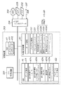
図3は、本実施形態のハードウエア構成例を示すブロック図である。ここでは、特に記憶装置203の構成例を詳細に示す。
【0029】
201は図1の制御装置であるCPUであり、ROM41とRAM42とディスクやCDなどの外部記憶装置43とが図1の記憶装置203に相当する。206は、図1と同様の表示装置204、出力装置205、入力装置202に、新たに通信手段207を接続する入出力インタフェースである。ここで、制御装置201と記憶装置203とは、図1の装置であっても図2のホストであっても同様の構成である。
【0030】
ROM41には、変更を必要としないプログラム411やパラメータ412が格納されている。
【0031】
RAM42はプログラムやデータを一時記憶する記憶領域であり、データ領域421とプログラムロード領域422からなる。プログラムロード領域422には、外部記憶装置43からOSやプリンタドライバなどのシステムプログラム、あるいはユーザなどから提供されるアプリケーションプログラムがロードされて、CPU201により実行される。
【0032】
データ領域421には、本実施形態で使用する領域として、例えば出力画像データを記憶する領域421a(後述の出力画像のXY軸方向の幅IX,IYも記憶する)、ユーザあるいはアプリケーションによる出力指示情報を記憶する領域421b(後述のフル印刷フラグやセンタリングフラグも記憶する。尚、前記フラグを別々に有さず、1つの領域充填フラグを設けてもよい)、出力領域情報を記憶する領域421c(後述の印刷領域のXY軸方向の幅PX,PYも記憶する。このPX,PYは予め接続される出力装置に対応して固定されても良いが、出力装置に問い合わせて獲得するようにするのが好ましい)、変倍率を記憶する領域421d(ここで、変倍率としたのは、本実施形態の説明では画像の拡大の場合を説明するが、印刷領域より大きな画像を縮小することもあり、当業者には拡大のアルゴリズムから容易に縮小のアルゴリスムが理解可能であり、本発明はこれをも含むものである)、画像の90°回転を記憶する領域421eとを有する。尚、本実施形態での処理途中の画像データや処理完了後の画像データを記憶する領域も、データ領域421に確保される。あるいは、受信された出力画像データ421aを保持する必要がなければ、この領域を兼用してもよい。
【0033】
外部記憶装置43は固定されたハードディスクやメモリカード、あるいは着脱可能で携帯可能なフロッピーディスクやCD等の光ディスク、磁気や光カード、ICカード、メモリカードなどを含むものであり、データ領域431とプログラム領域432からなる。
【0034】
プログラム領域432には、RAM42のプログラムロード領域422にロードされて実行される(メモリカードなどでは直接実行されてよい)プログラムが記憶される。図3には、本実施形態で使用されるプリンタドライバ301が図示されているが、OSやBIOSなどのシステムプログラムや、アプリケーションプログラムも記憶されている。図3には、更にプリンタドライバ301の一部の本実施形態に関連する印刷データ作成部301aを構成するモジュールが示されている。画像変倍モジュール432aはフル印刷フラグがオンの場合に印刷領域(印刷媒体)を画像が一杯になるように画像を変倍(本実施形態では拡大)するモジュール、画像センタリング・モジュール432bはセンタリングフラグがオンの場合に画像を印刷領域(印刷媒体)の中央に移動するモジュール、画像カッティング・モジュール432cは印刷しようとする画像が印刷領域(印刷媒体)より大きい(はみ出す)場合に、はみ出た部分をカットするモジュール、画像回転モジュール432dはカッティングする画像がなるべく少なくなるように必要な場合に画像を回転するモジュールである。
【0035】
<本実施形態の画像処理システムの動作例>
以下に、上記構成の画像処理システムの動作例を、図4から図6に示すフローチャートと、図7から図22に示す印刷領域(印刷媒体)と画像データとの関係を示す図とを参照しながら、説明する。尚、以下では画像を拡大する例を示すが、上述のように本発明は画像を縮小する処理も含むものである。
【0036】
(プリンタドライバの一部処理手順例)
図4は、プリンタドライバ301の本実施形態に係る部分を示すフローチャートである。
【0037】
まず、ステップS41でユーザあるいはアプリケーションからの印刷指示を待つ。ユーザあるいはアプリケーションからの印刷指示には、画像データの選択や印刷サイズの選択などの他に、フル印刷フラグとセンタリングフラグの設定がそれぞれに対応したソフトボタンや1つの印刷データ作成のソフトボタン、あるいはアプリケーションからのパラメータの転送により行われる。画像データは出力データの記憶領域421aに、パラメータは出力指示情報の記憶領域421bに記憶される。
【0038】
次に、ステップS42で印刷データ作成処理を行なう。印刷データ作成処理については、図5で更に詳細に処理手順を後述する。ステップS42の印刷データ作成処理で処理された画像データは、ステップS43で印刷装置に送信される。
【0039】
(印刷データ作成処理S42の手順例)
図5は、フル印刷機能とセンタリング機能を含む図4の印刷データ作成処理(S42)の手順例を示すフローチャートである。図5で印刷領域を印刷媒体と等しくすれば、印刷媒体一杯(フチなし)の印刷となるのは明らかである。すなわち、フチなし印刷とフチありの通常印刷との違いは、基本的には印刷領域が異なるだけである。フチなし印刷ではメディアにはみ出すように画像を作成して印刷することで、余白のないデータを作成する。本例では、ステップS205はスキップする。
【0040】
まず、図7に、本例の印刷媒体(図7のメディア220)と、画像(図7の221)と、印刷領域(図7の222)の関係を示す。図5のステップS206で、フル印刷機能オン(フル印刷フラグのオン)か否か判断する、オンであれば、ステップS207で画像アスペクト比を保持したまま、印刷領域に余白ができないように画像を拡大する(図8参照)。拡大された画像データはRAM42に一時記憶する。尚、拡大処理には補間処理が含まれるのは当然である。フル印刷機能オフの場合には拡大処理は行わない。ここでは、画像の縦の長さが印刷領域いっぱいになるような拡大率でよいが、画像と印刷領域によっては横の長さが印刷領域いっぱいになるような拡大率になる場合もある。この場合分けは後ほど詳細に説明する。
【0041】
次に、ステップS208でセンタリングオン(センタリングフラグのオン)か否か判断する、オンであればステップS209で画像のセンタリングを行う(図9参照)。センタリングオフであれば、画像のセンタリングが行わない。尚、センタリング処理は、画像がはみ出す方向にはみ出し量が両側で同等となるように画像を移動する処理であり、詳細は説明しない。センタリングを行った画像データはRAM42に一時記憶する。
【0042】
ステップS210で印刷領域からはみ出した部分(図9では223,224)を削除して印刷データを作成し(図10参照)、RAM42に一時記憶する。
【0043】
したがって、ユーザはフル印刷機能オンかつセンタリングオンとする(あるいは印刷データ作成オンとする)ことで、容易に画像の中心のデータを印刷領域(印刷媒体)に余白なく印刷可能である。
【0044】
(画像の拡大処理S207の手順例)
画像と印刷領域によって余白ができないように画像を拡大する場合に、拡大方法の場合分けが必要なので説明する。
【0045】
まず、図17から図22を参照して、本例の処理原理を説明する。
【0046】
図17において、印刷領域の横方向の長さをPX, 印刷領域の縦方向の長さをPY, 印刷画像の横方向の長さをIX, 印刷画像の縦方向の長さをIYとする。
ここで以下のアスペクト比を求めると、式(1)が成立するので、
IY/IX<PY/PX ...式(1)
印刷領域に余白がでないような拡大率は縦の長さの比率(PY/IY)になり、RAM42の変倍率の記憶領域421dに記憶する。この場合、拡大後の画像(図18参照)の大きき(横OX,縦OY)は、以下の式(2)(3)ようになる。
【0047】
OX = IX × (PY/IY) ...式(2)
OY = PY ...式(3)
逆に、図19においてアスペクト比を求めると、以下の式(4)のようになるので、
IY/IX>=PY/PX ...式(4)
印刷領域に余白がでないような拡大率は横の長さの比率(PX/IX)になる。すなわち、拡大後の画像(図20参照)の大きき(横OX,縦OY)は、以下の式(5)(6)ようになる。
【0048】
OX = PX ...式(5)
OY = PY × (PX/IX) ...式(6)
又、図17から図20のPX<PYの印刷領域と異なり、PX>PYの印刷領域の場合は、例えば図21においてアスペクト比を求めると、以下の式(4)のようになるので、
IY/IX>=PY/PX ...式(4)
印刷領域に余白がでないような拡大率は横の長さの比率(PX/IX)になる。すなわち、拡大後の画像(図22参照)の大きき(横OX,縦OY)は、以下の式(5)(6)ようになる。
【0049】
OX = PX ...式(5)
OY = PY × (PX/IX) ...式(6)
尚、画像を縮小する場合は、アスペクト比を反転させて式(1)及び式(4)を使用するか、同様にアスペクト比を求めて式(1)と式(4)の不等号を逆にすればよい。そして、画像の縮小処理では間引きや変倍処理が実行される。
【0050】
図6は、本例における図5のステップS207の画像の拡大処理の手順例を示すフローチャートである。尚、ここでは、ステップS61の処理はスキップする。
【0051】
まず、ステップS62で拡大基準軸がX軸かY軸かを判別する。すなわち、上記式(1)を満足するか式(4)を満足するかが判定される。式(1)を満足する場合にはステップS63に進んで、Y軸を基準軸として倍率を(PY/IY)から算出してRAM42の変倍率の記憶領域421dに記憶する。一方、式(4)を満足する場合にはステップS64に進んで、X軸を基準軸として倍率を(PX/IX)から算出してRAM42の変倍率の記憶領域421dに記憶する。
【0052】
ステップS65では、変倍率の記憶領域421dに記憶された変倍率に従って、ステップS63から進んだ場合は、式(2)及び(3)に従って画像を拡大してRAM42に一時記憶する。ステップS64から進んだ場合は、式(5)及び(6)に従って画像を拡大してRAM42に一時記憶する。
【0053】
(印刷データ作成処理S42の他の手順例)
本例では、図11から図16を参照して、フチなし印刷でなるべく画像を切り取る量を軽減する例を説明する。
【0054】
まず、上記手順例の前に、ステップS205で、なるべく画像を切り取る量を軽減するための処理を行う。図11に、印刷媒体(図11のメディア230)と、印刷画像(図11の231)と、印刷領域(図11の232)の関係を示す。ここで印刷領域のアスペクト比(PY/PX)と画像のアスペクト比(IY/IX)を計算する(図12参照)。
【0055】
IY/IX<1.0 且つ PY/PX<1.0 ...式(7)
又は、IY/IX>=1.0 且つ PY/PX>=1.0 ...式(8)
ステップS205−1で分岐し、上記式(7)及び(8)が成立した場合は画像を切り取る部分が少ないことを意味するので、回転不要なので画像の方向はそのままで処理を続行してよい。しかしながら、上記式(7)と(8)の少なくともいずれかが成立しない場合には、図13のように画像を90度回転した方が画像の切り取る量を抑えることができるので、ステップS205−2で画像を90度(図13の例では右に)回転した後に、回転した画像データをRAM42に記憶してから、次の処理に進む。
【0056】
図13に、印刷媒体(図13のメディア233)と、画像(図13の234)と、印刷領域(図13の235)の関係を示す。図5のステップS206で、フル印刷機能オンか否か判断する、オンであれば、ステップS207で画像アスペクト比を保持したまま印刷領域に余白ができないように画像を拡大して、RAM42に一時記憶する(図14参照)。フル印刷機能オフの場合には拡大処理は行わない。ここでは、画像の縦の長さが印刷領域いっぱいになるような拡大率でよいが、画像と印刷領域によっては横の長さが印刷領域いっぱいになるような拡大率になる場合もある。この場合分けは、上述の場合と同様である。
【0057】
次に、ステップS208でセンタリングオンか否か判断する、オンであればステップS209で画像のセンタリングを行い、RAM42に一時記憶する(図15参照)。センタリングオフであれば、画像のセンタリングが行わない。ステップS210で印刷領域からはみ出した上下部分(236,237)を削除してRAM42に一時記憶し(図16参照)、この印刷データを印刷装置に送信する。
【0058】
したがって、ユーザはフル印刷機能オンかつセンタリングオンとすることで容易に画像の中心のデータを印刷領域に余白なくフチなし印刷可能である。
【0059】
尚、上記実施形態では、図5の印刷データ作成処理に画像の回転処理を組み込んだが、図6の画像の拡大処理の手順の最初に組み込んでも同様の処理が可能である。この場合には、フル印刷オンの場合のみに画像を回転するか否かが判定されて実行される。
【0060】
又、本発明は、複数の機器(例えばホストコンピュータ、インターフェイス機器、リーダ、プリンタなど)から構成されるシステムに適用しても、複数の機能を有する一つの機器からなる装置に適用してもよい。
【0061】
又、前述のように、本発明の目的は、前述した実施形態の機能を実現するソフトウェアのプログラムコードを記録した記憶媒体(または記録媒体)を、システムあるいは装置に供給し、そのシステムあるいは装置のコンピュータ(またはCPUやMPU)が記憶媒体に格納されたプログラムコードを読み出し実行することによっても、達成されることは言うまでもない。この場合、記憶媒体から読み出されたプログラムコード自体が前述した実施形態の機能を実現することになり、そのプログラムコードを記憶した記憶媒体は本発明を構成することになる。又、コンピュータが読み出したプログラムコードを実行することにより、前述した実施形態の機能が実現されるだけでなく、そのプログラムコードの指示に基づき、コンピュータ上で稼働しているオペレーティングシステム(OS)などが実際の処理の一部または全部を行い、その処理によって前述した実施形態の機能が実現される場合も含まれることは言うまでもない。
【0062】
更に、記憶媒体から読み出されたプログラムコードが、コンピュータに挿入された機能拡張カードやコンピュータに接続された機能拡張ユニットに備わるメモリに書込まれた後、そのプログラムコードの指示に基づき、その機能拡張カードや機能拡張ユニットに備わるCPUなどが実際の処理の一部または全部を行い、その処理によって前述した実施形態の機能が実現される場合も含まれることは言うまでもない。
【0063】
本発明を上記記憶媒体に適用する場合、その記憶媒体には、先に説明したフローチャートに対応するプログラムコードを含むプログラムコードが格納されることになる。
【0064】
【発明の効果】
以上説明したように、本発明によれば、ユーザによる簡単な操作で出力領域一杯になるような出力処理を実現する画像処理方法及びそれを実現する装置及びプリンタドライバを提供できる。
【0065】
すなわち、ユーザは容易にフル印刷機能とセンタリング機能を組み合わせることで印刷領域に余白なく印刷することが可能である。又、専用のアプリケーションがなくても本発明のプリンタドライバがあればよい。特に、フチなし印刷対応の画像処理装置においてはさらに有効である。
【図面の簡単な説明】
【図1】本実施形態の画像処理システムの構成例を示すブロック図である。
【図2】本実施形態の画像処理システムの他の構成例を示すブロック図である。
【図3】本実施形態の画像処理システムの制御部の構成例を示すブロック図である。
【図4】本実施形態のプリンタドライバの一部処理手順例を示すフローチャートである。
【図5】図4の印刷データ作成処理S42の処理手順例を示すフローチャートである。
【図6】図5の画像の拡大処理S207の処理手順例を示すフローチャートである。
【図7】本実施形態に関するフル印刷機能及びセンタリング機能を行う前の画像配置の一例を示す図である。
【図8】図7の画像に本実施形態に関するフル印刷機能を行った画像の例を示す図である。
【図9】図8の画像に本実施形態に関するセンタリング機能を行った画像の例を示す図である。
【図10】図10の画像に本実施形態に関する印刷領域をはみ出た部分をカットした画像の例を示す図である。
【図11】本実施形態に関するフル印刷機能及びセンタリング機能を行う前の画像配置の他例を示す図である。
【図12】図11において本実施形態に関するアスペクト比を説明するための図である。
【図13】図11の図に本実施形態に関する右に90度回転した画像を示す図である。
【図14】図13の画像に本実施形態に関するフル印刷機能を行った画像の例を示す図である。
【図15】図14の画像に本実施形態に関するセンタリング機能を行った画像の例を示す図である。
【図16】図15の画像に本実施形態に関する印刷領域をはみ出た部分をカットした画像の例を示す図である。
【図17】本実施形態に関するフル印刷時の拡大率の計算例を示す図である。
【図18】本実施形態に関するフル印刷時した印刷領域の横がはみ出る場合の画像を示す図である。
【図19】本実施形態に関するフル印刷時の拡大率の計算例を示す他の図である。
【図20】本実施形態に関するフル印刷時した印刷領域の縦がはみ出る場合の画像を示す図である。
【図21】本実施形態に関するフル印刷時の拡大率の計算例を示す更に他の図である。
【図22】本実施形態に関するフル印刷時した印刷領域の縦がはみ出る場合の画像を示す図である。[0001]
[Industrial application fields]
The present invention relates to an image processing method, an apparatus for realizing the image processing method, and a printer driver. More particularly, the present invention relates to an image processing method for using the entire print area of a print medium and printing the central portion of an image without cutting out the image as much as possible. The present invention relates to a device and a printer driver to be realized.
[0002]
[Prior art]
2. Description of the Related Art Conventionally, for example, when an image to be synthesized on a personal computer is output by a printer, there is a fit page printing function that allows an image to fit in a print area by a printer driver or the like. In addition, there is a centering function that is a function of arranging an image in the center of the print medium.
[0003]
[Problems to be solved by the invention]
However, there is a demand for printing an image in a full printing area, and in particular, printers having a borderless printing function have become mainstream in recent printers, and a technique for printing on a printing medium without a blank space is desired. If this method is to be realized with the function of the conventional printer driver, first, a method in which the user cuts the image data itself to the same aspect ratio as that of the print medium and fits it to a borderless print area can be considered. . Secondly, a method in which the user uses the enlargement / reduction function to perform enlargement processing so that the print medium protrudes greatly can be considered. Or, thirdly, a method of enlarging an image so that an application can automatically print on a print medium without margins in cooperation with a printer driver.
[0004]
However, in the first and second methods, which are extensions of the above-described prior art, manual work by the user occupies the majority, requiring specialized knowledge and slowing down the processing time. In the third method, there is a problem that printing cannot be easily performed in an environment where there is no dedicated application.
[0005]
SUMMARY OF THE INVENTION The present invention provides an image processing method that realizes output processing that fills an output area with a simple operation by a user, an apparatus that realizes the image processing, and a printer driver.
[0008]
[Means for Solving the Problems]
In order to solve the above problems, an image processing method according to the present invention includes:,Print mediaAn image processing method for outputting a desired image without margins,printingPrint area larger than mediaAnd set the output area of the desired image to include the print area.An image scaling process for scaling the desired image at the same ratio in length and width, and an image scaled in the image scaling processThe output area ofThe printing areaPosition where the protruding amount is the same on both sides in the protruding directionAnd an output position moving step for moving the image output position;An output prohibiting step for prohibiting output of the protruding portion when the output region of the image whose magnification has been changed and moved the output position protrudes from the print region;It is characterized by having.
[0009]
here,in frontIn the image scaling process, scaling is performed so that at least one of the vertical and horizontal directions matches the print area. In the image scaling step,AboveA scaling ratio is determined based on a comparison between the aspect ratio of the print area and the aspect ratio of the desired image. In the case of enlargement of the image, when the aspect ratio of the print area is larger, the vertical length of the image is If the aspect ratio of the print area is smaller, the image is scaled so that the width of the image matches the print area. Further, prior to the image scaling step, the image further includes an image rotation step of rotating the image by 90 ° so that a portion where the scaled image protrudes from the print area is reduced. Further, in the image rotation step, it is determined whether or not to rotate based on the aspect ratio of the print area and the aspect ratio of the desired image. If both the aspect ratio and the aspect ratio are the same, the rotation is performed. If the aspect ratio of 1 is opposite, the rotation is performed. Also,in frontBoth processes are executed by the printer driver.
[0012]
or,The image processing apparatus of the present inventionImage output deviceprintingAn image processing apparatus for creating image data to be output to a medium, wherein the image output apparatusprintingPrint area larger than mediaIs set so that the output area of the desired image includes the print area.Image scaling means for generating image data obtained by scaling a desired image at the same vertical and horizontal ratio, and an image scaled by the image scaling meansThe output area ofIs the print areaPosition where the protruding amount is the same on both sides in the protruding directionOutput position moving means for generating image data for moving the image output position;Output prohibiting means for prohibiting the output of the protruding portion so that the output region of the image that has been scaled and moved the output position does not extend beyond the print region.It is characterized by having.
[0013]
here,in frontThe recording image scaling means scales the image so that at least one of the vertical and horizontal directions matches the print area. The image scaling means isAboveA scaling ratio is determined based on a comparison between the aspect ratio of the print area and the aspect ratio of the desired image. In the case of enlargement of the image, when the aspect ratio of the print area is larger, the vertical length of the image is If the aspect ratio of the print area is smaller, the image is scaled so that the width of the image matches the print area. Further, the image processing apparatus further includes image rotation means for generating image data obtained by rotating the image by 90 ° so that a portion where the scaled image protrudes from the print area is reduced. Further, the image rotation means determines whether to rotate based on the aspect ratio of the print area and the aspect ratio of the desired image, and performs rotation when the magnitude of the aspect ratio is equal to 1. If the aspect ratio of 1 is opposite, the rotation is performed. Also,in frontAny of these means is included in the printer driver.
[0016]
or,The printer driver of the present inventionImage output devicemarkA printer driver for creating image data to be output to a printing medium, wherein the image output deviceprintingPrint area larger than mediaIs set so that the output area of the desired image includes the print area.An image scaling module that generates image data obtained by scaling a desired image at the same aspect ratio, and an image scaled by the image scaling moduleThe output area ofIs the print areaPosition where the protruding amount is the same on both sides in the protruding directionAnd an output position moving module for generating image data in which the image output position moves.An output prohibiting module for prohibiting output of the protruding portion so that the output region of the image that has been scaled and moved in the output position does not extend beyond the print region.It is characterized by having.
[0017]
here,in frontIn the recording image scaling module, scaling is performed so that at least one of the vertical and horizontal directions matches the print area. In addition, the image scaling module isAboveA scaling ratio is determined based on a comparison between the aspect ratio of the print area and the aspect ratio of the desired image. In the case of enlargement of the image, when the aspect ratio of the print area is larger, the vertical length of the image is The image is scaled so as to match the print area, and when the aspect ratio of the print area is smaller, the scaled image is scaled so that the side of the image matches the print area. It further has an image rotation module for generating image data obtained by rotating the image by 90 ° so that the number of portions is reduced. Further, the image rotation module determines whether to rotate based on the aspect ratio of the print area and the aspect ratio of the desired image, and performs rotation when the magnitude of the aspect ratio is equal to 1. If the aspect ratio of 1 is opposite, the rotation is performed.
[0018]
The present invention also provides a storage medium for storing the printer driver in a computer-readable manner.
[0019]
DETAILED DESCRIPTION OF THE INVENTION
Hereinafter, embodiments of the present invention will be described with reference to the accompanying drawings.
[0020]
<Example of Configuration of Image Processing System of Present Embodiment>
FIG. 1 is a block diagram showing a configuration of an image processing system showing an embodiment of the present invention. In FIG. 1, a local
[0021]
The
[0022]
The
[0023]
For example, an image read by a scanner (not shown) or an image sent via a communication means is stored in the
[0024]
As described above, the image created and output by this apparatus is generally the gradation data of each of the luminance signals R, G, and B, and color correction, color conversion, Gradation correction and quantization processing are performed.
[0025]
Of course, the application of the present invention is not limited to the apparatus as described above. For example, it is well known that color conversion processing is performed in an apparatus such as a copying machine, and it is obvious that the present invention can be applied to such an apparatus or system.
[0026]
FIG. 2 is a diagram showing an example of an image processing system that is remotely connected via a communication means such as a LAN or the Internet instead of the local
[0027]
An
[0028]
FIG. 3 is a block diagram illustrating a hardware configuration example of the present embodiment. Here, a configuration example of the
[0029]
[0030]
The
[0031]
The
[0032]
In the
[0033]
The
[0034]
The
[0035]
<Operation Example of Image Processing System According to this Embodiment>
Hereinafter, an operation example of the image processing system having the above configuration will be described with reference to the flowcharts shown in FIGS. 4 to 6 and the diagrams showing the relationship between the print area (print medium) and the image data shown in FIGS. While explaining. Although an example of enlarging an image is shown below, the present invention includes processing for reducing an image as described above.
[0036]
(Example of printer driver partial processing procedure)
FIG. 4 is a flowchart showing a portion of the
[0037]
First, in step S41, a print instruction from the user or application is awaited. In addition to image data selection and print size selection, the print instruction from the user or application includes a soft button corresponding to the setting of the full print flag and the centering flag, one soft button for creating print data, or This is done by transferring parameters from the application. The image data is stored in the output
[0038]
Next, print data creation processing is performed in step S42. The print data creation process will be described later in detail with reference to FIG. The image data processed in the print data creation process in step S42 is transmitted to the printing apparatus in step S43.
[0039]
(Procedure example of print data creation processing S42)
FIG. 5 is a flowchart showing an example of the procedure of the print data creation process (S42) of FIG. 4 including the full print function and the centering function. If the print area is made equal to the print medium in FIG. 5, it is clear that the print medium is full (borderless). That is, the difference between borderless printing and bordered normal printing is basically only the printing area. In borderless printing, data without margins is created by creating and printing an image that protrudes from the media. In this example, step S205 is skipped.
[0040]
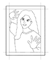
First, FIG. 7 shows the relationship between the print medium (
[0041]
Next, in step S208, it is determined whether or not centering is on (centering flag is on). If it is on, image centering is performed in step S209 (see FIG. 9). If centering is off, image centering is not performed. The centering process is a process of moving the image so that the amount of protrusion is the same on both sides in the direction in which the image protrudes, and details thereof will not be described. The centered image data is temporarily stored in the
[0042]
In step S210, the portion (223, 224 in FIG. 9) that protrudes from the print area is deleted to create print data (see FIG. 10), which is temporarily stored in the RAM.
[0043]
Therefore, the user can easily print the data at the center of the image in the print area (print medium) without a blank space by turning on the full printing function and turning on centering (or turning on print data creation).
[0044]
(Procedure example of image enlargement processing S207)
Since the case of enlarging a method is necessary when enlarging an image so that there is no blank space depending on the image and the print area, a description will be given.
[0045]
First, the processing principle of this example will be described with reference to FIGS.
[0046]
In FIG. 17, the horizontal length of the print area is PX, the vertical length of the print area is PY, the horizontal length of the print image is IX, and the vertical length of the print image is IY.
Here, when the following aspect ratio is obtained, the formula (1) is established.
IY / IX <PY / PX ... Formula (1)
The enlargement ratio such that there is no margin in the print area is the ratio of the vertical length (PY / IY), and is stored in the variable
[0047]
OX = IX × (PY / IY) (2)
OY = PY ... Formula (3)
Conversely, when the aspect ratio is obtained in FIG. 19, the following equation (4) is obtained.
IY / IX> = PY / PX ... Formula (4)
The enlargement ratio such that there is no margin in the print area is the ratio of the horizontal length (PX / IX). That is, the enlarged image (see FIG. 20) (horizontal OX, vertical OY) is expressed by the following equations (5) and (6).
[0048]
OX = PX ... Formula (5)
OY = PY × (PX / IX) (6)
Also, unlike the printing area of PX <PY in FIGS. 17 to 20, in the case of the printing area of PX> PY, for example, when the aspect ratio is obtained in FIG. 21, the following equation (4) is obtained.
IY / IX> = PY / PX ... Formula (4)
The enlargement ratio such that there is no margin in the print area is the ratio of the horizontal length (PX / IX). That is, the enlarged image (see FIG. 22) (horizontal OX, vertical OY) is expressed by the following equations (5) and (6).
[0049]
OX = PX ... Formula (5)
OY = PY × (PX / IX) (6)
When reducing the image, use the expressions (1) and (4) by reversing the aspect ratio, or calculate the aspect ratio in the same manner and reverse the inequality signs in the expressions (1) and (4). do it. In the image reduction process, thinning and scaling processes are executed.
[0050]
FIG. 6 is a flowchart illustrating a procedure example of the image enlargement process in step S207 of FIG. 5 in the present example. Here, the process of step S61 is skipped.
[0051]
First, in step S62, it is determined whether the enlargement reference axis is the X axis or the Y axis. That is, it is determined whether the expression (1) is satisfied or the expression (4) is satisfied. If the expression (1) is satisfied, the process proceeds to step S63, and the magnification is calculated from (PY / IY) using the Y axis as a reference axis and stored in the variable
[0052]
In step S65, if the process proceeds from step S63 according to the scaling factor stored in the scaling
[0053]
(Another procedure example of the print data creation process S42)
In this example, an example in which the amount of image cut out is reduced as much as possible by borderless printing will be described with reference to FIGS.
[0054]
First, before the above procedure example, in step S205, a process for reducing the amount of cropping the image as much as possible is performed. FIG. 11 shows the relationship among the print medium (the medium 230 in FIG. 11), the print image (231 in FIG. 11), and the print area (232 in FIG. 11). Here, the aspect ratio (PY / PX) of the print area and the aspect ratio (IY / IX) of the image are calculated (see FIG. 12).
[0055]
IY / IX <1.0 and PY / PX <1.0 Formula (7)
Or IY / IX> = 1.0 and PY / PX> = 1.0 (8)
If branching occurs in step S205-1 and the above expressions (7) and (8) are satisfied, it means that there are few portions to cut out the image. Therefore, since rotation is not necessary, the processing may be continued with the image direction unchanged. However, if at least one of the above equations (7) and (8) does not hold, the amount of image cropping can be reduced by rotating the image 90 degrees as shown in FIG. After rotating the image 90 degrees (to the right in the example of FIG. 13), the rotated image data is stored in the
[0056]
FIG. 13 shows the relationship among the print medium (
[0057]
Next, it is determined in step S208 whether or not centering is on. If it is on, the image is centered in step S209 and temporarily stored in the RAM 42 (see FIG. 15). If centering is off, image centering is not performed. In step S210, the upper and lower portions (236, 237) protruding from the print area are deleted, temporarily stored in the RAM 42 (see FIG. 16), and the print data is transmitted to the printing apparatus.
[0058]
Therefore, the user can easily print the data at the center of the image without margins in the print area by turning on the full printing function and centering on.
[0059]
In the above-described embodiment, the image rotation process is incorporated in the print data creation process of FIG. 5, but the same process can be performed even if it is incorporated at the beginning of the procedure of the image enlargement process of FIG. In this case, it is determined whether or not to rotate the image only when full printing is on.
[0060]
Further, the present invention may be applied to a system constituted by a plurality of devices (for example, a host computer, an interface device, a reader, a printer, etc.), or may be applied to an apparatus composed of a single device having a plurality of functions. .
[0061]
Further, as described above, the object of the present invention is to supply a storage medium (or recording medium) on which a program code of software that realizes the functions of the above-described embodiments is supplied to a system or apparatus, and the system or apparatus. Needless to say, this can also be achieved by a computer (or CPU or MPU) reading and executing the program code stored in the storage medium. In this case, the program code itself read from the storage medium realizes the functions of the above-described embodiments, and the storage medium storing the program code constitutes the present invention. Further, by executing the program code read by the computer, not only the functions of the above-described embodiment are realized, but also an operating system (OS) running on the computer based on the instruction of the program code. It goes without saying that a case where the function of the above-described embodiment is realized by performing part or all of the actual processing and the processing is included.
[0062]
Further, after the program code read from the storage medium is written in a memory provided in a function expansion card inserted into the computer or a function expansion unit connected to the computer, the function is determined based on the instruction of the program code. It goes without saying that the CPU or the like provided in the expansion card or the function expansion unit performs part or all of the actual processing and the functions of the above-described embodiments are realized by the processing.
[0063]
When the present invention is applied to the above-described storage medium, the storage medium stores program codes including program codes corresponding to the flowcharts described above.
[0064]
【The invention's effect】
As described above, according to the present invention, it is possible to provide an image processing method that realizes an output process that fills an output area with a simple operation by a user, an apparatus that realizes the output process, and a printer driver.
[0065]
In other words, the user can easily print in the print area with no margin by combining the full printing function and the centering function. Further, the printer driver of the present invention is sufficient even if there is no dedicated application. In particular, this is more effective in an image processing apparatus compatible with borderless printing.
[Brief description of the drawings]
FIG. 1 is a block diagram illustrating a configuration example of an image processing system according to an embodiment.
FIG. 2 is a block diagram illustrating another configuration example of the image processing system according to the present exemplary embodiment.
FIG. 3 is a block diagram illustrating a configuration example of a control unit of the image processing system according to the present exemplary embodiment.
FIG. 4 is a flowchart illustrating an example of a partial processing procedure of the printer driver according to the embodiment.
FIG. 5 is a flowchart illustrating an example of a processing procedure of print data creation processing S42 in FIG. 4;
6 is a flowchart illustrating an example of a processing procedure of image enlargement processing S207 in FIG. 5;
FIG. 7 is a diagram illustrating an example of an image arrangement before performing a full printing function and a centering function according to the present embodiment.
8 is a diagram illustrating an example of an image obtained by performing a full print function related to the present embodiment on the image of FIG. 7;
9 is a diagram illustrating an example of an image obtained by performing a centering function related to the present embodiment on the image of FIG. 8;
10 is a diagram illustrating an example of an image obtained by cutting a portion that protrudes from a print region related to the present embodiment in the image of FIG.
FIG. 11 is a diagram illustrating another example of the image layout before performing the full printing function and the centering function according to the present embodiment.
FIG. 12 is a diagram for explaining an aspect ratio related to the present embodiment in FIG. 11;
FIG. 13 is a diagram showing an image rotated 90 degrees to the right according to the present embodiment in the diagram of FIG.
14 is a diagram illustrating an example of an image obtained by performing a full print function according to the present embodiment on the image of FIG. 13;
15 is a diagram illustrating an example of an image obtained by performing a centering function related to the present embodiment on the image of FIG. 14;
FIG. 16 is a diagram illustrating an example of an image obtained by cutting a portion that protrudes from a print region related to the present embodiment in the image of FIG. 15;
FIG. 17 is a diagram illustrating a calculation example of an enlargement ratio at the time of full printing according to the present embodiment.
FIG. 18 is a diagram illustrating an image when a side of a print area is projected in full printing according to the present embodiment.
FIG. 19 is another diagram showing a calculation example of the enlargement ratio at the time of full printing according to the present embodiment.
FIG. 20 is a diagram illustrating an image in a case where the vertical length of the print area is projected during full printing according to the present embodiment.
FIG. 21 is still another diagram illustrating a calculation example of the enlargement ratio at the time of full printing according to the present embodiment.
FIG. 22 is a diagram illustrating an image when the vertical length of the print area is projected during full printing according to the present embodiment.
Claims (18)
前記印刷媒体より大きい印刷領域を設定し、所望の画像の出力領域が該印刷領域を包含する大きさに前記所望の画像を縦横同じ率で変倍する画像変倍工程と、
該画像変倍工程で変倍した画像の前記出力領域が前記印刷領域からはみ出す方向にはみ出し量が両側で同等となる位置に、画像出力位置を移動する出力位置移動工程と、
前記変倍して出力位置を移動した画像の前記出力領域が前記印刷領域をはみ出す場合に、該はみ出す部分の出力を禁止する出力禁止工程とを有することを特徴とする画像処理方法。An image processing method for outputting a desired image without margins on a print medium ,
An image scaling step for setting a print area larger than the print medium, and scaling the desired image at the same ratio in length and width so that the output area of the desired image includes the print area ;
A position protrusion amount in a direction in which the output region of the image scaled in the image scaling step protrudes from the printing area is the same on both sides, and an output position moving step of moving the image output position,
An image processing method comprising: an output prohibiting step of prohibiting output of a protruding portion when the output region of the image whose output position has been changed by scaling is protruding from the printing region .
前記画像出力装置が、前記印刷媒体より大きい印刷領域を設定し、所望の画像の出力領域が該印刷領域を包含する大きさに前記所望の画像を縦横同じ率で変倍した画像データを生成する画像変倍手段と、
該画像変倍手段で変倍した画像の前記出力領域が前記印刷領域からはみ出す方向にはみ出し量が両側で同等となる位置に、画像出力位置が移動する画像データを生成する出力位置移動手段と、
前記変倍して出力位置を移動した画像の前記出力領域が前記印刷領域をはみ出して出力されないように、該はみ出す部分の出力を禁止する出力禁止手段とを有することを特徴とする画像処理装置。An image processing apparatus for creating image data to be output to a print medium by an image output apparatus,
The image output device sets a print area larger than the print medium, and generates image data obtained by scaling the desired image at the same vertical and horizontal ratio so that the output area of the desired image includes the print area. Image scaling means;
A position protrusion amount in a direction in which the output region of the image scaled in the image scaling unit protrudes from the printing area is the same on both sides, and an output position moving means for the image output position to generate image data to be moved,
An image processing apparatus , comprising: an output prohibiting unit that prohibits output of the protruding portion so that the output region of the image that has been scaled and moved in the output position does not extend beyond the print region .
前記画像出力装置が、前記印刷媒体より大きい印刷領域を設定し、所望の画像の出力領域が該印刷領域を包含する大きさに前記所望の画像を縦横同じ率で変倍した画像データを生成する画像変倍モジュールと、
該画像変倍モジュールで変倍した画像の前記出力領域が前記印刷領域からはみ出す方向にはみ出し量が両側で同等となる位置に、画像出力位置が移動する画像データを生成する出力位置移動モジュールと、
前記変倍して出力位置を移動した画像の前記出力領域が前記印刷領域をはみ出して出力されないように、該はみ出す部分の出力を禁止する出力禁止モジュールとを有することを特徴とするプリンタドライバ。The image output device is a printer driver for creating image data to be output to the printing medium,
The image output device sets a print area larger than the print medium, and generates image data obtained by scaling the desired image at the same vertical and horizontal ratio so that the output area of the desired image includes the print area. An image scaling module;
An output position moving module that generates image data in which the image output position moves to a position where the amount of protrusion of the output area of the image scaled by the image scaling module is equal on both sides in the direction of protruding from the print area ;
A printer driver , comprising: an output prohibiting module for prohibiting the output of the protruding portion so that the output region of the image whose output position has been changed by scaling is not output beyond the printing region .
Priority Applications (2)
| Application Number | Priority Date | Filing Date | Title |
|---|---|---|---|
| JP2002072555A JP4143314B2 (en) | 2002-03-15 | 2002-03-15 | Image processing method, apparatus for realizing the same, and printer driver |
| US10/385,425 US7995219B2 (en) | 2002-03-15 | 2003-03-12 | Image processing method and apparatus, and printer driver |
Applications Claiming Priority (1)
| Application Number | Priority Date | Filing Date | Title |
|---|---|---|---|
| JP2002072555A JP4143314B2 (en) | 2002-03-15 | 2002-03-15 | Image processing method, apparatus for realizing the same, and printer driver |
Publications (3)
| Publication Number | Publication Date |
|---|---|
| JP2003274155A JP2003274155A (en) | 2003-09-26 |
| JP2003274155A5 JP2003274155A5 (en) | 2004-11-25 |
| JP4143314B2 true JP4143314B2 (en) | 2008-09-03 |
Family
ID=28035174
Family Applications (1)
| Application Number | Title | Priority Date | Filing Date |
|---|---|---|---|
| JP2002072555A Expired - Lifetime JP4143314B2 (en) | 2002-03-15 | 2002-03-15 | Image processing method, apparatus for realizing the same, and printer driver |
Country Status (2)
| Country | Link |
|---|---|
| US (1) | US7995219B2 (en) |
| JP (1) | JP4143314B2 (en) |
Families Citing this family (20)
| Publication number | Priority date | Publication date | Assignee | Title |
|---|---|---|---|---|
| JP3788643B2 (en) * | 1996-10-22 | 2006-06-21 | 富士写真フイルム株式会社 | Photo printing system |
| JP3915430B2 (en) * | 2001-04-25 | 2007-05-16 | セイコーエプソン株式会社 | Split printing control |
| AU2003248391B2 (en) * | 2002-09-26 | 2005-06-09 | Canon Information Systems Research Australia Pty Ltd | Efficient Printing of Frames Pages |
| AU2002951709A0 (en) | 2002-09-26 | 2002-10-17 | Canon Information Systems Research Australia Pty Ltd | Efficient printing of frames pages |
| US8223355B2 (en) | 2003-06-16 | 2012-07-17 | Hewlett-Packard Development Company, L.P. | Cellular telephone protocol adaptive printing |
| CN1306383C (en) * | 2004-01-02 | 2007-03-21 | 致伸科技股份有限公司 | Image printing method |
| JP4872192B2 (en) * | 2004-07-09 | 2012-02-08 | Nkワークス株式会社 | Photo printing system |
| KR100675861B1 (en) * | 2004-11-29 | 2007-02-02 | 삼성전자주식회사 | Terminal device for converting image by using preview screen and method thereof |
| JP4572830B2 (en) * | 2005-06-30 | 2010-11-04 | セイコーエプソン株式会社 | Printing system and printing method |
| KR100746002B1 (en) | 2005-07-27 | 2007-08-06 | 삼성전자주식회사 | Method and apparatus for displaying wallpaper |
| JP2007143109A (en) * | 2005-10-17 | 2007-06-07 | Riso Kagaku Corp | Image reading device and printing system |
| JP4645512B2 (en) * | 2006-04-06 | 2011-03-09 | 富士ゼロックス株式会社 | Image forming apparatus |
| JP2009218702A (en) * | 2008-03-07 | 2009-09-24 | Dainippon Printing Co Ltd | Typesetting device, typesetting method and typesetting processing program |
| JP5528081B2 (en) * | 2009-12-10 | 2014-06-25 | キヤノン株式会社 | Information processing apparatus control method, information processing apparatus, and program |
| JP2011210088A (en) * | 2010-03-30 | 2011-10-20 | Brother Industries Ltd | Print controlling device, program, printer, and print controlling system |
| US8599391B2 (en) * | 2010-04-28 | 2013-12-03 | Konica Minolta Laboratory U.S.A., Inc. | Multiple media type printing |
| JP2012095007A (en) * | 2010-10-25 | 2012-05-17 | Kyocera Mita Corp | Image forming apparatus and image forming program |
| JP2015215702A (en) * | 2014-05-08 | 2015-12-03 | キヤノン株式会社 | Printing system, print support device, and method |
| TWI581636B (en) * | 2016-05-23 | 2017-05-01 | 鴻海精密工業股份有限公司 | Screen display ratio adjusting aparatus and method |
| KR102583879B1 (en) * | 2021-01-04 | 2023-09-27 | 주식회사 디지털포토 | Apparatus for editing printing region and method thereof |
Family Cites Families (35)
| Publication number | Priority date | Publication date | Assignee | Title |
|---|---|---|---|---|
| US4200392A (en) * | 1979-01-02 | 1980-04-29 | Polaroid Corporation | Photographic copy apparatus with cropping feature |
| JPH0748795B2 (en) * | 1982-07-09 | 1995-05-24 | 富士写真フイルム株式会社 | Image input / output device |
| JPS5938791A (en) * | 1982-08-30 | 1984-03-02 | 株式会社東芝 | Image display |
| US4799080A (en) * | 1985-10-19 | 1989-01-17 | Sanyo Electric Co., Ltd. | Electrophotographic copying machine having editorial function |
| US4928252A (en) * | 1988-02-24 | 1990-05-22 | Digital Equipment Corporation | Printing apparatus and method for printing a plurality of pages onto a single sheet |
| US5956466A (en) * | 1991-04-01 | 1999-09-21 | Canon Kabushiki Kaisha | Image processor capable of operation as a facsimile |
| JP3395196B2 (en) * | 1992-01-27 | 2003-04-07 | ソニー株式会社 | Video signal transmission method and playback device |
| US5311259A (en) * | 1992-06-19 | 1994-05-10 | Minolta Camera Kabushiki Kaisha | Image forming apparatus |
| US5546474A (en) * | 1993-12-21 | 1996-08-13 | Hewlett-Packard Company | Detection of photo regions in digital images |
| US5796877A (en) * | 1995-12-11 | 1998-08-18 | Xerox Corporation | Method and apparatus for automatically fitting an input image to the size of the output document |
| US5745659A (en) * | 1996-04-25 | 1998-04-28 | Hewlett-Packard Company | Versatile scaling of drawings |
| JPH1051755A (en) * | 1996-05-30 | 1998-02-20 | Fujitsu Ltd | Screen display controller for video conference terminal equipment |
| JPH1044513A (en) * | 1996-08-07 | 1998-02-17 | Olympus Optical Co Ltd | Code printer and code print medium applied thereto |
| JP3615327B2 (en) | 1996-10-29 | 2005-02-02 | 富士写真フイルム株式会社 | Digital printing device |
| JP4346705B2 (en) * | 1997-04-28 | 2009-10-21 | 富士フイルム株式会社 | Computer-readable recording medium recording a driver program for a photographic printer |
| JP3440804B2 (en) * | 1998-01-23 | 2003-08-25 | セイコーエプソン株式会社 | Printing apparatus, printing method, and recording medium |
| US6018397A (en) * | 1998-02-13 | 2000-01-25 | Eastman Kodak Company | Digital image processing with indication to user of hardcopy output image quality |
| JP3362680B2 (en) | 1998-03-16 | 2003-01-07 | セイコーエプソン株式会社 | PRINT PROCESSING METHOD, RECORDING MEDIUM RECORDING COMPUTER PROGRAM FOR USING THE SAME, AND PRINTER |
| US6175653B1 (en) * | 1998-05-12 | 2001-01-16 | Xerox Corporation | Fast decompression and rotation for devices with asymmetric resolution |
| US6912311B2 (en) * | 1998-06-30 | 2005-06-28 | Flashpoint Technology, Inc. | Creation and use of complex image templates |
| US6109745A (en) * | 1998-07-17 | 2000-08-29 | Eastman Kodak Company | Borderless ink jet printing on receivers |
| DE19941672A1 (en) * | 1998-09-09 | 2000-03-16 | Fuji Photo Film Co Ltd | Image reader for image generation system, performs control measurement using slower transport speed, or using longer image reading interval image cannot be read correctly due to density |
| US6456732B1 (en) * | 1998-09-11 | 2002-09-24 | Hewlett-Packard Company | Automatic rotation, cropping and scaling of images for printing |
| US6456745B1 (en) * | 1998-09-16 | 2002-09-24 | Push Entertaiment Inc. | Method and apparatus for re-sizing and zooming images by operating directly on their digital transforms |
| US6559971B1 (en) * | 1998-10-27 | 2003-05-06 | Hewlett-Packard Development Co., L.P. | Self-resizing demonstration page for a printing device |
| JP3903405B2 (en) | 1999-10-29 | 2007-04-11 | 富士フイルム株式会社 | Image conversion method and apparatus, and recording medium |
| US7808663B2 (en) * | 1999-12-07 | 2010-10-05 | Minolta Co., Ltd. | Apparatus, method and computer program product for processing document images of various sizes and orientations |
| US6282300B1 (en) * | 2000-01-21 | 2001-08-28 | Signafy, Inc. | Rotation, scale, and translation resilient public watermarking for images using a log-polar fourier transform |
| US7016869B1 (en) * | 2000-04-28 | 2006-03-21 | Shutterfly, Inc. | System and method of changing attributes of an image-based product |
| JP4633888B2 (en) | 2000-06-08 | 2011-02-16 | キヤノンファインテック株式会社 | Printing control apparatus and method |
| JP4054941B2 (en) * | 2000-08-10 | 2008-03-05 | セイコーエプソン株式会社 | PRINT IMAGE DISPLAY DEVICE, PRINT IMAGE DISPLAY METHOD, AND COMPUTER-READABLE RECORDING MEDIUM CONTAINING PRINT IMAGE DISPLAY PROCESSING PROGRAM |
| KR100374607B1 (en) * | 2001-01-06 | 2003-03-03 | 삼성전자주식회사 | A method for extending print area |
| US7133070B2 (en) * | 2001-09-20 | 2006-11-07 | Eastman Kodak Company | System and method for deciding when to correct image-specific defects based on camera, scene, display and demographic data |
| US6944355B2 (en) * | 2002-01-16 | 2005-09-13 | Xerox Corporation | Apparatus and methods for automatically adjusting images on edge-disturbed output media |
| US20030146997A1 (en) * | 2002-02-01 | 2003-08-07 | Eastman Kodak Company | System and method of processing a digital image for user assessment of an output image product |
-
2002
- 2002-03-15 JP JP2002072555A patent/JP4143314B2/en not_active Expired - Lifetime
-
2003
- 2003-03-12 US US10/385,425 patent/US7995219B2/en active Active
Also Published As
| Publication number | Publication date |
|---|---|
| JP2003274155A (en) | 2003-09-26 |
| US20030174346A1 (en) | 2003-09-18 |
| US7995219B2 (en) | 2011-08-09 |
Similar Documents
| Publication | Publication Date | Title |
|---|---|---|
| JP4143314B2 (en) | Image processing method, apparatus for realizing the same, and printer driver | |
| JPH1199724A (en) | Apparatus and method for laying out for printing, and storage medium | |
| JPH11219265A (en) | Intermediate film processing device in printer control system and medium for recording its control program | |
| JP6089801B2 (en) | Print control apparatus and program | |
| JP2007114833A (en) | Information processor and program | |
| JP2562514B2 (en) | Print control device and image data drawing method | |
| JP2008077160A (en) | Image processing device, image processing method, image forming apparatus, computer-executable program, and recording medium storing the program | |
| JP3902907B2 (en) | Image processing apparatus and method, and image forming apparatus | |
| JP3796409B2 (en) | Image processing apparatus, image forming apparatus, information processing apparatus, and methods thereof | |
| KR20090126836A (en) | Image forming apparatus, image forming system and enlargement print processing method of printing data | |
| JP4336470B2 (en) | Drawing control apparatus, drawing control method and program | |
| JP4109836B2 (en) | Print data generation method, print data generation apparatus, computer program, and storage medium | |
| JP3897539B2 (en) | Print data generation method and apparatus | |
| JP2005142614A (en) | Scanner driver program, information processing apparatus, and copy system | |
| JP2005047137A (en) | Image arrangement method, image arrangement device, and image arrangement program | |
| JP2006019931A (en) | Apparatus and method for image processing, computer program, and storage medium | |
| JPH11253675A (en) | Picture data processor for patchwork and medium for recording picture data processing program for patchwork | |
| JPH11185019A (en) | Device and method for processing image | |
| JP2002096506A (en) | Rasterizing method, print controller, print system, and medium having program recorded therein | |
| JP2784823B2 (en) | Image editing printing method of printer | |
| JP2003237190A (en) | Print system, printer driver and method for controlling printer | |
| JP2000022927A (en) | Method and device for image processing | |
| JP4402681B2 (en) | Image processing apparatus, image processing method, program, and storage medium | |
| JPH064064A (en) | Pattern generation system | |
| JP2005182267A (en) | Print controller |
Legal Events
| Date | Code | Title | Description |
|---|---|---|---|
| A977 | Report on retrieval |
Free format text: JAPANESE INTERMEDIATE CODE: A971007 Effective date: 20050705 |
|
| A131 | Notification of reasons for refusal |
Free format text: JAPANESE INTERMEDIATE CODE: A131 Effective date: 20050729 |
|
| A521 | Request for written amendment filed |
Free format text: JAPANESE INTERMEDIATE CODE: A523 Effective date: 20050927 |
|
| A02 | Decision of refusal |
Free format text: JAPANESE INTERMEDIATE CODE: A02 Effective date: 20060313 |
|
| A521 | Request for written amendment filed |
Free format text: JAPANESE INTERMEDIATE CODE: A523 Effective date: 20060512 |
|
| A911 | Transfer to examiner for re-examination before appeal (zenchi) |
Free format text: JAPANESE INTERMEDIATE CODE: A911 Effective date: 20060529 |
|
| A912 | Re-examination (zenchi) completed and case transferred to appeal board |
Free format text: JAPANESE INTERMEDIATE CODE: A912 Effective date: 20060922 |
|
| A521 | Request for written amendment filed |
Free format text: JAPANESE INTERMEDIATE CODE: A523 Effective date: 20080513 |
|
| A01 | Written decision to grant a patent or to grant a registration (utility model) |
Free format text: JAPANESE INTERMEDIATE CODE: A01 |
|
| A61 | First payment of annual fees (during grant procedure) |
Free format text: JAPANESE INTERMEDIATE CODE: A61 Effective date: 20080616 |
|
| FPAY | Renewal fee payment (event date is renewal date of database) |
Free format text: PAYMENT UNTIL: 20110620 Year of fee payment: 3 |
|
| R150 | Certificate of patent or registration of utility model |
Ref document number: 4143314 Country of ref document: JP Free format text: JAPANESE INTERMEDIATE CODE: R150 Free format text: JAPANESE INTERMEDIATE CODE: R150 |
|
| FPAY | Renewal fee payment (event date is renewal date of database) |
Free format text: PAYMENT UNTIL: 20120620 Year of fee payment: 4 |
|
| FPAY | Renewal fee payment (event date is renewal date of database) |
Free format text: PAYMENT UNTIL: 20120620 Year of fee payment: 4 |
|
| FPAY | Renewal fee payment (event date is renewal date of database) |
Free format text: PAYMENT UNTIL: 20130620 Year of fee payment: 5 |
|
| EXPY | Cancellation because of completion of term |