JP3796409B2 - Image processing apparatus, image forming apparatus, information processing apparatus, and methods thereof - Google Patents
Image processing apparatus, image forming apparatus, information processing apparatus, and methods thereof Download PDFInfo
- Publication number
- JP3796409B2 JP3796409B2 JP2001009127A JP2001009127A JP3796409B2 JP 3796409 B2 JP3796409 B2 JP 3796409B2 JP 2001009127 A JP2001009127 A JP 2001009127A JP 2001009127 A JP2001009127 A JP 2001009127A JP 3796409 B2 JP3796409 B2 JP 3796409B2
- Authority
- JP
- Japan
- Prior art keywords
- gradation drawing
- gradation
- image processing
- color
- data
- Prior art date
- Legal status (The legal status is an assumption and is not a legal conclusion. Google has not performed a legal analysis and makes no representation as to the accuracy of the status listed.)
- Expired - Lifetime
Links
Images


Classifications
-
- G—PHYSICS
- G06—COMPUTING; CALCULATING OR COUNTING
- G06K—GRAPHICAL DATA READING; PRESENTATION OF DATA; RECORD CARRIERS; HANDLING RECORD CARRIERS
- G06K15/00—Arrangements for producing a permanent visual presentation of the output data, e.g. computer output printers
- G06K15/02—Arrangements for producing a permanent visual presentation of the output data, e.g. computer output printers using printers
Description
【0001】
【発明の属する技術分野】
本発明は画像出力装置及び方法に関する。特に、ホストコンピュータ等の外部機器装置によって作成されたページ述言語(以後、PDLとする)データを受信し、ページ記述言語データを解析して、ラスタライズしたラスタデータをエンジンに出力する画像形成装置に好適な画像出力装置及び方法に関する。
【0002】
【従来の技術】
近年、ホストコンピュータにおけるDTP(Desk Top Publishing)やプレゼンテーションソフトが高機能化し、容易に複雑な描画を表現することができるようになってきた。これらのアプリケーションソフトにより印刷を行う場合、複雑な描画データはプリンタドライバによって最適なPDLデータに変換され、プリンタに送信される。プリンタが受信したPDLデータは、プリンタコントローラにおいて解析処理を行い、コマンドに従って高速に展開処理し、プリンタエンジンのパフォーマンスを落とすことなく高速かつ高画質な出力を実現している。
【0003】
【発明が解決しようとする課題】
しかしながら、ピクセル間で色を少しずつ変えて描画するグラデーション描画を行う場合、プリンタドライバでグラデーション描画コマンドのPDLデータをプリンタに送信し、プリンタコントローラにおいて展開すると、
・グラデーション描画領域の全ての色を算出するのに非常に時間がかかる。
・グラデーション描画領域が大きいと非常に多くのメモリを必要とする。
といった課題がある。
【0004】
また、ホストコンピュータのプリンタドライバにおいてグラデーション描画コマンドの展開処理を行う場合には、
・データ量の増加に伴ない、データ転送に時間がかかる。
といった問題がある。
【0005】
結局、グラデーション描画においては、その展開処理をプリンタコントローラ側で行っても、ホストコンピュータ側で行っても、プリント処理のスループット、すなわちプリンタエンジンのパフォーマンスを低下させる要因となってしまう。
【0006】
本発明は上記の課題に鑑みてなされたものであり、プリント処理のスループット、すなわちプリンタエンジンのパフォーマンスの低下を招くことなくグラデーション描画処理を遂行できる画像処理装置及び方法を提供することを目的とする。
【0007】
【課題を解決するための手段】
上記の目的を達成するための本発明による画像処理装置は、
グラデーション描画領域内における色の変化の度合いを取得する取得手段と、前記取得手段で取得した色の変化の度合いに基づいて、前記グラデーション描画領域内の間引きレベルを決定する決定手段と、
前記グラデーション描画領域内の画素の色値を、前記間引きレベルによって決定される画素間隔で算出する算出手段とを備える。
【0008】
また、上記の目的を達成するための本発明による画像処理方法は、
グラデーション描画領域内における色の変化の度合いを取得する取得工程と、前記取得工程で取得した色の変化の度合いに基づいて、前記グラデーション描画領域内の間引きレベルを決定する決定工程と、
前記グラデーション描画領域内の画素の色値を、前記間引きレベルによって決定される画素間隔で算出する算出工程とを備える。
【0009】
また、本発明によれば、上記の画像処理方法を用いた画像形成装置及び方法、情報処理装置及び方法が提供される。
【0010】
【発明の実施の形態】
以下、添付の図面を参照して本発明の好適な実施形態を説明する。
【0011】
<第1実施形態>
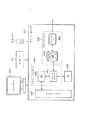
図1は第1の実施形態による画像形成システムの概略構成を示すブロック図である。
【0012】
図1において101はホストコンピュータ等の外部機器、102は本実施形態によるグラデーション描画処理を行うレーザビームプリンタである。レーザビームプリンタ102において、105はプリンタエンジン部であり、イメージデータに基づいて周知の電子写真プロセスによって感光ドラム上に潜像を形成し、該潜像を現像し、これを用紙に転写して定着することにより画像記録を行う。また、103はコントローラ部であり、プリンタエンジン部105に接続され、ホストコンピュータ等の外部機器101から送られるコードデータ(ESCコード、各種PDL等)を受け、このコードデータに基づいてドットデータからなるページ情報を生成し、プリンタエンジン部105に対して所定のインターフェース手段によってイメージデータを送信する。104はユーザ(操作者)とのインターフェースを行うパネル部であり、ユーザはパネル部104を操作することによって、プリンタ102に所定の動作を指示することができる。
【0013】
図2は第1の実施形態によるレーザビームプリンタ102の機構模式図である。
【0014】
図2において、201はプリンタ筐体、202は操作パネルである。操作パネル202には操作のためのスイッチ及びLED表示器、LCD表示器が配されている。これは図1において示したパネル部104の物理的側面である。203は制御ボード収納部であり、プリンタの印字プロセス制御を行うプリンタエンジン部105及び、プリンタ全体の制御とホストコンピュータからのデータを解析し、イメージデータに変換するプリンタコントローラ部103が収納される。
【0015】
210は用紙を保持する用紙カセットであり、不図示の仕切り板によって電気的に用紙サイズを検知する機構を有する。211はカセット給紙クラッチであり、用紙カセット210上に裁置された用紙の最上位の用紙一枚のみを分離し、不図示の駆動手段によって分離した用紙を給紙ローラ212まで搬送させるカムである。カセット給紙クラッチ211は、給紙の度に間欠的に回転し、1回転に対応して1枚の用紙を給紙する。214はレジストシャッタであり、用紙を押圧して給紙を停止させる。給紙ローラ212は、用紙の先端部をレジストシャッタ214まで搬送する。219は手差し用トレイである。また、215は手差し給紙クラッチである。手差し給紙クラッチ215は用紙の先端をレジストシャッタ214まで搬送する。以上のような構成によって用紙カセット210及び手差し給紙用トレイ219から選択的に用紙を給紙することが可能となる。
【0016】
プリンタエンジン部105は、プリンタコントローラ部103と所定の通信プロトコルによって通信を行い、プリンタコントローラ部103からの指示によって、カセット210、または手差し用トレイ219の中から採用する給紙手段を決定する。そして、印字開始指示によって上記の通り給紙を開始し用紙をレジストシャッタ214まで搬送する。
【0017】
204はカートリッジであり、感光ドラム205及び、不図示のトナー保持部を有する。206はレーザドライバ、207は回転多面鏡、208は反射ミラー、209はビームディテクタである。レジストシャッタ214まで用紙が搬送されると、プリンタコントローラ部103から送られたイメージデータに応じてレーザドライバによってオンオフ駆動される不図示の半導体レーザから発射されるレーザビームは、回転多面鏡207により主走査方向に走査され反射ミラーを介して感光ドラム205上に導かれ結像し、主走査方向に走査して主走査ライン上に潜像を形成する。このレーザビームの発射に同期してレジストシャッタ214は上方に駆動し、用紙の搬送をレーザビームの走査に同期させる。レーザビームの走査開始位置に配置されたビームディテクタ209は、レーザビームを検出することによって主走査の画像書出しタイミングを決定するための同期信号を形成し、プリンタコントローラ部103に送る。
【0018】
その後用紙は、搬送ローラ213によって搬送され、感光ドラムは不図示のモータによって回転駆動され、現像器220によってトナー像として顕像化された後、用紙上に転写される。トナー像が転写された用紙はその後、定着ローラ216によりトナー像が加熱定着され、搬送ローラ217を経て、排紙ローラ218によりプリンタ筐体の排紙トレイに排紙される。
【0019】
図3は、第1の実施形態によるプリンタコントローラ部103の構成を示すブロック図である。
【0020】
図3において、301はパネルインターフェイスであり、パネル部104とのデータ通信によって、操作者からの諸設定、指示をパネル部104から受けとる。302はホストインターフェイスであり、ホストコンピュータ等の外部機器101との信号の入出力部である。303はエンジンインターフェイスであり、エンジン部105との信号の入出力部として機能し、不図示の出力バッファレジスタからデータ信号送出を行なうとともにプリンタエンジン部105との通信制御を行なう。
【0021】
304はCPUであり、プリンタコントローラ部103全体の制御を司る。305は読み出し専用メモリ(ROM)であり、CPU304によって実行される、以下の310〜314に示される処理機能を実現するための制御コードを格納する。
【0022】
310はデータ解析部であり、ホストインターフェース302において受信したデータを解析し、所定の処理に振り分ける。311は間引きレベル判定部であり、データ解析部310においてグラデーション描画であると判定されたときに、当該グラデーション描画の間引きレベルを決定する。312はエッジ位置算出部であり、グラデーション描画におけるスキャンライン毎のエッジの座標を計算する。313はグラデーションデータ作成部であり、エッジ位置算出部により算出されたエッジ間のピクセルそれぞれに対するデータを作成する。314は描画処理部であり、作成されたデータをラスタデータに展開する。データ解析部310、間引き判定部311、エッジ位置算出部312、グラデーション作成部313、描画処理部314は、それぞれROM305に格納された制御プログラムであり、CPU304がこれらの制御プログラムを実行することにより実現される機能である。
【0023】
306はRAMであり、CPU304の使用する一時記憶用メモリであり、以下のメモリ領域を含む。315は受信バッファであり、ホストインターフェース302において受信したデータを一時的に格納しておく。316は頂点情報メモリであり、グラデーション描画において指定された座標と色情報を格納する。317はオブジェクトメモリであり、グラデーション作成部313において作成されたグラデーションイメージを含む、種々のオブジェクトイメージを格納する。318はラスタメモリであり、オブジェクトメモリ317に格納されたオブジェクトを描画処理部314によって所定の解像度、階調に展開したデータを格納する。
【0024】
307はエンジンインターフェイスであり、不揮発性のメモリ手段であるEEPROMで構成される。308はDMA制御部であり、CPU304からの指示によりラスタメモリ内のビットマップデータを、エンジンインターフェイス303に転送する。
【0025】
309は、アドレスバス及びデータバスを持つシステムバスである。上述したパネルインターフェイス301、ホストインターフェイス302、エンジンインターフェース303、CPU309、ROM305、RAM306、EEPROM307及びDMA制御部308は、各々システムバス309に接続され、システムバス309上にある全ての機能部にアクセス可能である。
【0026】
なお、CPU304を制御する制御コードは、不図示のシステムクロックによってタスクと称されるロードモジュール単位に時分割制御するOSと、機能単位に動作する複数のロードモジュール(タスク)によって構成されるものとする。
【0027】
次に、ホスト側のシステムの説明を行う。図4は、第1の実施形態におけるホストコンピュータ等の外部機器101の概略構成を説明するブロック図である。図4において401はホストコンピュータであり、プリントデータ及び制御コードを含む印刷情報を印刷装置300に出力する。ホストコンピュータ401は、入力デバイスであるところのキーボード411やポインティングデバイスであるところのマウス412と、表示デバイスであるディスプレイ410を合わせた一つのコンピュータ・システムとして構成されている。なお、本実施形態では、ホストコンピュータ401は、MS−DOS(商標)、Windows(商標)などの基本OSによって動作しているものとする。
【0028】
ホストコンピュータ401について、本実施形態に関する機能的な部分に注目し、基本OS上での機能を大きく分類すると、アプリケーション402、画像情報処理手段であるところのグラフィックシステム403、データ格納部、印刷データ格納制御部および印刷装置との通信部を含むスプールシステム404、ユーザインターフェイスを実現するUI処理部405に大別される。
【0029】
アプリケーション402は、例えば、ワープロや表計算などの基本ソフトウェア上で動作する応用ソフトウェアを指すものである。グラフィックシステム403は、基本OSの機能の一部であるGraphic Device Interface(以後、GDIと記す)406とそのGDIから動的にリンクされるデバイスドライバであるところのプリンタドライバ407によって構成されている。ここでプリンタドライバ407はGDIとしてコールされる描画命令を、PDL言語に変換するのが大きな役割である。GDI描画命令やドライバの設定により本実施形態に関連するグラデーション描画命令を受け取り、適切な処理を行う。
【0030】
スプールシステム404は、グラフィックシステム403の後段に位置するプリンタ特有のシステムであり、グラフィックシステム403において作成されたPDLデータを一時的に格納するスプーラ408と、スプーラ408に格納されたPDLデータを読み出し、印刷装置であるレーザビームプリンタ102に送信するプリンタI/F409から構成されるものである。
【0031】
基本OSによって、上述したこれらの名称や機能的な枠組みは若干異なる場合があるが、本実施形態で言う各技術的手段が実現できるモジュールであればよく、それらの名称や枠組みは本実施形態において実質的なものではない。例えば、スプーラと呼ばれるものは、別のOSにおいてプリント・キューと呼ばれるモジュールに処理を組み込むことによっても実現可能である。
【0032】
なお一般的に、これらの各機能モジュールを含むホストコンピュータ401は、図示しないが中央演算処理装置(CPU)、リードオンリーメモリ(ROM)、ランダムアクセスメモリ(RAM)、ハードディスクドライブ(HDD)、各種入出力制御部(I/O)などのハードウェアのもとで、基本ソフトと呼ばれるソフトウェアがその制御を司り、その基本ソフトの元で、それぞれの応用ソフト、システムプロセスが機能モジュールとして動作するようになっている。
【0033】
次に本実施形態のグラデーション描画の処理について説明する。
【0034】
ユーザがアプリケーションなどを使って、プレゼンテーションデータやDTPデータを作成し、そのデータを印刷する場合、プリンタドライバはGDIとしてコールされる描画命令をPDLデータに変換する。このとき、グラデーション指定した図形が含まれていると、グラデーション指定した図形に対してグラデーション描画命令が発行される。
【0035】
発行されるグラデーション描画命令は3種類ある。すなわち、
(1)矩形の対角の2頂点の座標とそれぞれの頂点の色を指定し、一方の頂点の色からもう一方の頂点の色へ水平方向に変化させる水平グラデーション指定(図5)と、
(2)一方の頂点の色からもう一方の頂点の色へ垂直方向に変化させる垂直グラデーション指定(図6)と、
(3)三角形の3頂点の座標とそれぞれの頂点の色を指定し、3つの頂点内で色を変換させる三角グラデーション指定(図7)である。
【0036】
グラデーション描画命令も他の描画命令と同様にPDLデータに変換され、印刷装置(本実施形態ではレーザビームプリンタ102)に送信される。そして、プリンタコントローラにおいてこのグラデーション描画命令を受信すると、以下に示す式に従ってグラデーション描画を行う。
【0037】
(1)水平グラデーション指定における矩形領域内の色の算出
水平グラデーション指定における矩形領域内の色は以下の式で算出される。矩形の頂点1の座標を(X1, Y1)、色を(R1, G1, B1)とし、頂点2の座標を(X2, Y2)、色を(R2, G2, B2)とし、矩形領域内のある点の座標の(X, Y)の色(R, G, B)は
R = (R2 * (X - X1) + R1 * (X2 - X)) / (X2 - X1)
G = (G2 * (X - X1) + G1 * (X2 - X)) / (X2 - X1)
B = (B2 * (X - X1) + B1 * (X2 - X)) / (X2 - X1)
となる。水平方向グラデーションはY座標には依存せず、同じX座標の領域は全て同じ色で描画することとなる。
【0038】
(2)垂直グラデーション指定における矩形領域内の色の算出
垂直グラデーション指定における矩形領域内の色は以下の式で算出される。矩形の頂点1の座標を(X1, Y1)、色を(R1, G1, B1)とし、頂点2の座標を(X2, Y2)、色を(R2, G2, B2)とし、矩形領域内のある点の座標の(X, Y)の色(R, G, B)は
R = (R2 * (Y - Y1) + R1 * (Y2 - Y)) / (Y2 - Y1)
G = (G2 * (Y - Y1) + G1 * (Y2 - Y)) / (Y2 - Y1)
B = (B2 * (Y - Y1) + B1 * (Y2 - Y)) / (Y2 - Y1)
となる。垂直方向グラデーションはX座標には依存せず、同じY座標の領域は全て同じ色で描画することとなる。
【0039】
(3)三角グラデーション指定における三角形領域内の色の算出
三角グラデーション指定における三角形領域内の色は以下の式で算出される。三角形の頂点1の座標を(X1, Y1)、色を(R1, G1, B1)とし、頂点2の座標を(X2, Y2)、色を(R2, G2, B2)とし、頂点3の座標を(X3, Y3)、色を(R3, G3, B3)とし、三角形領域内のある点の座標の(X, Y)の色(R, G, B)は
R = (R1 * S1 + R2 * S2 + R3 * S3) / (S1 + S2 + S3)
G = (G1 * S1 + G2 * S2 + G3 * S3) / (S1 + S2 + S3)
B = (B1 * S1 + B2 * S2 + B3 * S3) / (S1 + S2 + S3)
、ここで、
S1は頂点2、頂点3、領域内座標(X, Y)を3つの頂点とした三角形の面積
S2は頂点1、頂点3、領域内座標(X, Y)を3つの頂点とした三角形の面積
S3は頂点1、頂点2、領域内座標(X, Y)を3つの頂点とした三角形の面積
となる。
【0040】
次に、本実施形態の印刷装置におけるグラデーション描画のフローチャートについて図8、図9、図10を用いて説明する。
【0041】
図8は印刷装置におけるデータ受信から出力までの処理を示したフローチャートである。ホストコンピュータ401のプリンタI/F409からPDLデータが送信されると、印刷装置102はホストI/F302を介してPDLデータを受信する(ステップS501)。受信されたPDLデータは逐次受信バッファ315に格納される。印刷装置102のデータ解析部310は、受信バッファ315に格納されたデータを読み出し、コマンド解析を行う(ステップS502)。このコマンドの解析結果に応じて各種処理が実行されることになる。
【0042】
このコマンド解析の結果により、当該コマンドがグラデーション描画であるかどうかが判定される(ステップS503)。グラデーション描画であった場合は、間引きレベル判定部311においてグラデーション描画における間引きレベルの算出を行う(ステップS504)。そして、算出された間引きレベルに基づいて拡大値を決定し、後のステップS506で作成される当該グラデーション描画領域のグラデーションイメージデータを、その拡大値で拡大して描画するよう描画処理部314に指定する(ステップS505)。更に、間引きレベルに従ってグラデーションイメージデータを作成し、オブジェクトメモリ317に格納する(ステップS506)。グラデーションイメージデータの作成が終了すると、残りのPDLについて再びデータ解析を行う。
【0043】
本実施形態では、間引きレベルの値から1を差し引いた数の画素が間引かれ、残った画素について上述したグラデーション描画における色値が算出される。たとえば、図12には、頂点A,B,Cを有する三角形のグラデーション描画領域が示されている。そして、当該描画領域中の一走査ライン(1100画素)について詳細が示されている。図12に示されるように、間引きレベルが4に指定されると(mabiki=4)、ステップS506では4−1=3個の画素が間引かれて、4画素毎に(3画素おきに)グラデーション描画の色値が計算される。すなわち、図12において、×印の画素についてはグラデーション描画の色地は算出されないことになる。この結果、グラデーション描画は、1/4に縮小されたものとなるので、ステップS505において間引きレベル4を拡大値として設定し、ラスタメモリへの展開描画時には、当該グラデーション画像を4倍するのである。
【0044】
なお、ステップS504における間引きレベルの算出と、ステップS506におけるグラデーションイメージデータの作成については図9、図10のフローチャートを参照して更に後述する。
【0045】
一方、コマンド解析によりグラデーション描画以外の描画コマンドと判定された場合は、コマンドに対応した描画データを作成しオブジェクトメモリ317に格納する(ステップS503,S507、S508)。当該描画コマンドに関する描画を完了したならば、残りのPDLについて再びデータ解析を行う。
【0046】
更に、データ解析において当該コマンドがページ終了コマンドと判定した場合は、描画処理部314においてオブジェクトメモリ317に格納されている描画データをラスタメモリ318に所定の解像度、諧調で展開処理し、出力する(ステップS503,S507,S509)。
【0047】
次に、ステップS504における間引きレベルの算出処理について説明する。図9は第1の実施形態による間引きレベル算出の詳細処理を示したフローチャートである。
【0048】
まず、グラデーション描画命令により2点指定された矩形領域または、3点指定された三角形領域を含む矩形領域の幅Wdを算出する(ステップS601)。なお、以下の説明では、グラデーション描画領域として矩形領域或いは三角形領域を挙げて説明するが、他の多角形領域についても同様の手法で適用できることは、本実施形態の説明から当業者には明らかであろう。
【0049】
次に、当該グラデーション描画領域における全体の色の変化量に対応する色数Cnumを算出する(ステップS602)。
【0050】
ここで、幅Wdと色数Cnumの算出式は次のようになる。すなわち、グラデーション描画領域が2点指定の矩形領域の場合、当該矩形の頂点1の座標を(X1, Y1)、色を(R1, G1, B1)とし、頂点2の座標を(X2, Y2)、色を(R2, G2, B2)として、幅Wdは、
Wd = abs(X2 - X1) + 1
となり、色数Cnumは、
R = abs(R2 - R1) + 1
G = abs(G2 - G1) + 1
B = abs(B2 - B1) + 1
Cnum = max(R, G, B)
となる(ただし、absは絶対値を表す)。
【0051】
また、グラデーション描画領域が3点指定の三角形であった場合は、当該三角形の頂点1の座標を(X1, Y1)、色を(R1, G1, B1)とし、頂点2の座標を(X2, Y2)、色を(R2, G2, B2)とし、頂点3の座標を(X3, Y3)、色を(R3, G3 B3)として、幅Wdは、
Wd = max(X1, X2, X3) - min(X1, X2, X3) + 1
となり、色数Cnumは
R = max(R1, R2, R3) - min(R1, R2, R3) + 1
G = max(G1, G2, G3) - min(G1, G2, G3) + 1
B = max(B1, B2, B3) - min(B1, B2, B3) + 1
Cnum = max(R, G, B)
となる。
【0052】
結局、本実施形態では、グラデーション描画領域を囲む最小の矩形の幅がWdであり、当該グラデーション領域内における各色成分毎の輝度値の最大値と最小値との差のうち、最も大きい値を色数としている。なお、色数は、グレースケール(単色)の場合には、グレースケール値(輝度値)の最大値と最小値との差(「Cmax - Cmin」と表す)をとることになる。
【0053】
次に、以上のようにして得られた幅Wdを色数Cnumで除することにより、当該グラデーション描画における、1つの色変化に対する画素数を求め、求められた画素数に応じて間引きレベルを決定する。これは、グラデーション描画領域において1つの色が維持される画素数に対応するので、この画素数が大きいほどグラデーション描画における色変化の度合いは小さく、従って間引きレベルを大きくすることができる。
【0054】
本実施形態では、以上の算出式により算出したWd, CnumのWd/Cnumが16以上(ステップS603)の場合は、間引きレベルmabiki = 8とし(ステップS604)、Wd/Cnumが8以上16未満(ステップS605)の場合は、間引きレベルmabiki = 6とし(ステップS606)、Wd/Cnumが8未満の場合は、間引きレベルmabiki = 4とする(ステップS607)。
【0055】
なお、上記実施形態では、Wd/Cnumを用いたが、Cnum/Wdを求めることにより、グラデーション描画領域における色変化の程度を求め、これに応じて間引きレベルを決定する(すなわち、色変化が大きい場合は、色変化への追従性を挙げるために間引きレベルを小さくする)ようにしてもよい。Wd/Cnumを用いても、Cnum/Wdを用いても技術的意図が同じであることは明らかである。
【0056】
図11は、間引きレベル算出のフローチャートに従って間引きレベルを算出したときの一例を示した図である。グラデーション描画領域である三角形A,B,Cを囲む最小の矩形領域が点線で示されており、Wdはこの矩形領域の幅(Xmax - Xmin=1200)である。また、本図形が単色であるとすると、その色数はCnum = Cmax - Cmin = 255 - 102 = 153となる。従って、Wd/Cnumの値は約7となり、間引きレベル(mabiki)は4となる。
【0057】
ステップS506におけるグラデーションのイメージデータ作成は、以上の方法により算出した間引きレベルに応じて行われる。図10は図8のグラデーションイメージデータ作成(ステップS506)の詳細処理を示したフローチャートである。
【0058】
まず、ステップS701からS706では、グラデーション描画領域に指定された多角形を形成する辺を、ラスター順次で描画する際の左側エッジを決定する辺と右側エッジを決定する辺とに分けるとともに、ラスター走査を行うY座標の範囲(Ymin、Ymax)を決定する。ステップS701からS706では、その一例として、グラデーション描画領域が三角形の場合を示している。もちろん他の多角形についても類似の処理を適用できることは明らかであろう。
【0059】
まず、三角グラデーション指定の3点の最小Y座標の頂点をAとし、残りの2点のうち最小X座標の頂点をBとし、残りの頂点をCとする(ステップS701)。頂点BのY座標が頂点CのY座標より小さい場合(ステップS702)は、左エッジのスキャンする経路をA→B→C、右エッジのスキャンする経路をA→Cとし(ステップS703)、Y座標の最大値Ymaxに頂点CのY座標を設定する(ステップS704)。一方、頂点BのY座標が頂点CのY座標以上の場合は、左エッジのスキャンする経路をA→B、右エッジのスキャンする経路をA→C→Bとし(ステップS705)、Y座標の最大値Ymaxに頂点BのY座標を設定する(ステップS706)。
【0060】
以上の処理内容を図16を参照して更に説明する。図16は、左右エッジに対応する辺と、描画走査範囲の決定方法を説明する図である。
【0061】
図16(a)は、三角形のグラデーション描画領域を示しており、上記ステップS701の処理によって頂点A,B,Cが設定されている。そして、上記ステップS703とS705における左右エッジの決定は、Y座標が最大値の頂点とY座標が最小値の頂点を結ぶ線分によって多角形を構成する辺を分けることにより、各走査における左側端部と右側端部を決定する辺に分類することと同義である。たとえば図16の(a)では、三角形ABCの頂点A(Ymin)と頂点C(Ymax)を結ぶ線分により、辺AB及び辺BCの組と、辺ACに分類され、辺AB及び辺BCが各走査の左側端部を、辺ACが各走査の右側端部を決定することになる。
【0062】
なお、図16の(b)では、他の多角形として6角形の場合を示した。この場合も上記処理と同様の考え方で、Y座標が最小の頂点AとY座標が最大の頂点Dを結ぶ線分によって辺を分ける。そして、辺AB,BC,CDが各走査の左側エッジを決定する辺に設定され、辺AF,FE,EDが各走査の右側エッジを決定する辺に設定される。もちろん、多角形をラスター順次で描画する場合における走査範囲(Y座標範囲)は、全頂点のY座標のうちの最小値から最大値(すなわちYmin〜Ymax)である。
【0063】
また、図16(c)のように、Y軸に対して平行な辺(辺BC)が存在した場合は、その辺は実際に左右エッジを決める辺とはならず、処理上は左側エッジ、右側エッジのどちらの組に属してもかまわない。本実施形態では、ステップS702においてYb=Ycの場合にステップS703へ進むので、左側エッジを決定する辺として扱っている。
【0064】
また、図16(d)に示されるように、グラデーション描画領域が矩形の場合は、辺ABと辺CDがY軸と平行になるので、左側エッジを決める辺として辺ACが、右側エッジを決める辺として辺BDが選択される。
【0065】
以上のようにして、スキャンする経路が決まったら変数Yの初期値として頂点AのY座標(Ymin)を設定し(ステップS707)、ステップS714においてY>YmaxとなるまでステップS708〜S713の処理(ラスター順次によるグラデーション描画領域の描画)を繰り返す。
【0066】
ステップS708〜S713の処理について説明する。まず、Y座標における左エッジのX座標Xleftと右エッジのX座標Xrightを算出する(ステップS708)。次に、算出したXleftを変数Xに設定し(ステップS709)、座標(X, Y)の色を三角グラデーション指定の色算出式によって算出する(ステップS710)。算出した色の値はオブジェクトメモリ318に格納される。座標(X, Y)の色算出後、Xに間引きレベルmabikiを足し(ステップS711)、XとXrightを比較し(ステップS712)、XがXrightよりも大きくなるまでステップS710〜S712の処理を繰り返し行う。Y座標の1スキャンライン分のグラデーションイメージの作成が終了したら、Yをインクリメントし(ステップS713)、YとYmaxを比較して(ステップS714)、 YがYmaxより大きくなるまでステップS708〜S714の処理を繰り返し行う。
【0067】
以上のように、ステップS711で色を算出するピクセルを一定値ずつ(間引きレベルの値ずつ)スキップすることで色値算出の計算量を低減して処理効率を向上させ、色データに使用するメモリ量の削減を行っている。
【0068】
図12は、グラデーションイメージ作成のフローチャートに従って、スキャンラインのデータを作成したときの一例を示したものである。図12では間引きレベルが“4”であり、たとえば幅Wd=1100の部分のグラデーション描画がWd=275に縮小されていることがわかる。同様に、図15では、間引きレベルが“6”であり、たとえば幅Wd=1100の部分のグラデーション描画がWd=184に縮小されていることがわかる。
【0069】
以上説明したように、第1の実施形態によれば、グラデーション描画領域内における色の変化の度合いを考慮してグラデーション描画領域内の色値を算出するピクセルの間隔を決定し、決定されたピクセル間隔でグラデーション描画領域内の色を算出する。このような手法を用いることにより、画質の著しい低下を回避しつつ、グラデーション描画領域の色の算出時間を短縮し、また、メモリ使用量を削減することが可能となり、グラデーション描画処理によるパフォーマンス低下を回避することが可能となる。
【0070】
<第2実施形態>
第1実施形態においては、グラデーション描画領域が三角形であった場合に、当該三角形グラデーション領域を含む矩形領域の幅と色数により間引きレベルを算出している。第2の実施形態では、三角形グラデーション領域について、間引きレベルの算出の精度を更に向上させ、適切な間引きレベルによりグラデーションイメージを作成する。
【0071】
図13は第2の実施形態による間引きレベル算出(ステップS504)の詳細処理を示したフローチャートである。
【0072】
三角グラデーション指定の3点の最小Y座標の頂点をAとし、残りの2点のうち最小X座標の頂点をBとし、残りの頂点をCとする(ステップS1001)。頂点BのY座標Ybが頂点CのY座標Yc以下の場合(ステップS1002)は、Yに頂点BのY座標Yb(ステップS1003)、Xleftに頂点BのX座標Xbを設定し(ステップS1004)、さらにY座標がYbのときの右エッジの座標を頂点Aと頂点Cを結ぶ線上で算出し、Xrightに設定する(ステップS1005)。
【0073】
一方、頂点BのY座標Ybが頂点CのY座標Ycより大きい場合は、Yに頂点CのY座標Yc(ステップS1006)、Xrightに頂点CのX座標Xcを設定し(ステップS1007)、さらにY座標がYcのときの左エッジの座標を頂点Aと頂点Bを結ぶ線上で算出し、Xleftに設定する(ステップS1008)。
【0074】
以上のようにしてXleft, Xright, Yを設定した後、左エッジの(Xleft, Y)における色Cleftと、右エッジの(Xright, Y)における色Crightを算出し(ステップS1009、S1010)、XleftとXright間の幅Wdと色数Cnumを算出する(ステップS1011)。なお、幅Wdと色数Cnumの算出式は以下のとおりである。すなわち、Cleftを(Rleft, Gleft, Bleft)、Crightを(Rright, Gright, Bright)とすると、幅Wdは
Wd = Xright - Xleft + 1
となり、色数Cnumは
R = abs(Rleft - Rright) + 1
G = abs(Gleft - Gright) + 1
B = abs(Bleft - Bright) + 1
Cnum = max(R, G, B)
となる。なお、色数Cnumは、グレースケール(単色)の場合には、単にグレースケール値(輝度値)の差(Cleft - Cright + 1)をとることになる。
【0075】
そして、以上の算出式により算出したWd, CnumのWd/Cnumが16以上の場合は、間引きレベルmabiki = 8とし(ステップS1012、S1013)、Wd/Cnumが8以上16未満の場合は、間引きレベルmabiki = 6とし(ステップS1012、S1014、S1015)、Wd/Cnumが8未満の場合は、間引きレベルmabiki = 4とする(ステップS1012、S1014、S1016)。以上の方法により算出した間引きレベルに応じて、第1実施形態で上述したごとくグラデーションイメージデータ作成を行う。
【0076】
図14は、第2の実施形態による間引きレベル算出のフローチャートに従って間引きレベルを算出したときの一例を説明する図である。Yb<Ycであるので、頂点BのX座標がXleft(=100)に設定され、その点の色がCleft(=103)に設定される。また、Y=Ybのときの辺AC上の点のX座標がXriht(=1199)に設定され、その点の色がCright(=230)に設定される。そしてステップS1011からS1016の処理により、mabiki=6が得られる。
【0077】
以上のように、第2実施形態では、グラデーション描画においてもっとも長い走査範囲を有する部分における色の変化に基づいて間引きレベルを決定するので、間引きレベルの設定制度がより精度が向上する。
【0078】
なお、第2実施形態では、三角形のグラデーション描画領域について説明したが、描画領域が他の多角形であった場合でも、走査幅の最大位置を検出し、当該走査部分における色の変化の度合いを求めるようにすればよく、本実施形態の思想は一般的な多角形に適用可能である。
【0079】
なお、上記第1及び第2実施形態における間引きレベル算出方式は、4,6,8の3種類の間引きレベルに分けているが、条件をより詳細にしてさらに多くのレベル分けして、より適切な間引きレベルを算出するようにしてもよい。
【0080】
また、第1及び第2実施形態の間引きレベル算出方式は、サイズや色数だけで間引きレベルを算出しているが、出力解像度、出力階調などの画質に影響のある設定条件も考慮して、より適切な間引きレベルを算出するようにしてもよい。例えば、出力解像度が600dpiのときには間引きレベルを実施形態の通り8,4,2にし、300dpiのときは間引きレベルをそれぞれ4,2,1にする。解像度が低い場合にも同じように間引くと画像が劣化してしまう場合があるが、上記のようにすればこれを防止することができる。
【0081】
更に、第1及び第2実施形態においては、間引きレベル算出とグラデーションイメージ描画を主走査方向に対してのみ適用しているが、同様な方式により副走査方向に対しても適用するようにしてもよい。この場合、ステップS713において変数Yの値を間引きレベルに応じて増加することになる。なお、間引きレベル算出とこれを用いたグラデーションイメージ描画の副走査方向への適用は、上述した実施形態から当業者には明らかであるので、これ以上の説明を省略するが、このような適用により、図6に示すような、垂直グラデーション描画についても、水平グラデーション描画と同様の効果をあげることができる。
【0082】
更に、上記実施形態では、プリンタコントローラ側でグラデーション描画を実行するが、ホストコンピュータ側でグラデーション描画を行う場合にも本実施形態を適用できる。すなわち、ホストコンピュータ側で間引きレベルを算出して、グラデーション描画を行うことにより、間引きレベルで縮小されたグラデーション描画が得られるので、この縮小されたグラデーション描画と間引きレベルをプリンタコントローラに与えるようにする。プリンタコントローラ側では、送信されたグラデーション描画を間引きレベルに応じて拡大し、画像出力するようにする。このようにすれば、グラデーション描画については縮小画像が送信されるので、送信データ量が低減され、スループットの低下を防止できる。
【0083】
以上説明したように、上記各実施形態によれば、グラデーション描画においては、グラデーション描画の領域と領域内の色数を考慮して算出するピクセルの間隔を決定し、グラデーション描画領域内を算出したピクセル間隔で色を算出することにより、画質の著しい低下を回避しつつ、グラデーション描画領域の色の算出時間を短縮し、また、メモリ使用量を削減することが可能となり、パフォーマンス低下を回避することができる。
【0084】
また、本発明の目的は、前述した実施形態の機能を実現するソフトウェアのプログラムコードを記録した記憶媒体を、システムあるいは装置に供給し、そのシステムあるいは装置のコンピュータ(またはCPUやMPU)が記憶媒体に格納されたプログラムコードを読出し実行することによっても、達成されることは言うまでもない。
【0085】
この場合、記憶媒体から読出されたプログラムコード自体が前述した実施形態の機能を実現することになり、そのプログラムコードを記憶した記憶媒体は本発明を構成することになる。
【0086】
プログラムコードを供給するための記憶媒体としては、例えば、フロッピディスク,ハードディスク,光ディスク,光磁気ディスク,CD−ROM,CD−R,磁気テープ,不揮発性のメモリカード,ROMなどを用いることができる。
【0087】
また、コンピュータが読出したプログラムコードを実行することにより、前述した実施形態の機能が実現されるだけでなく、そのプログラムコードの指示に基づき、コンピュータ上で稼働しているOS(オペレーティングシステム)などが実際の処理の一部または全部を行い、その処理によって前述した実施形態の機能が実現される場合も含まれることは言うまでもない。
【0088】
さらに、記憶媒体から読出されたプログラムコードが、コンピュータに挿入された機能拡張ボードやコンピュータに接続された機能拡張ユニットに備わるメモリに書込まれた後、そのプログラムコードの指示に基づき、その機能拡張ボードや機能拡張ユニットに備わるCPUなどが実際の処理の一部または全部を行い、その処理によって前述した実施形態の機能が実現される場合も含まれることは言うまでもない。
【0089】
【発明の効果】
以上説明したように、本発明によれば、プリント処理のスループット、すなわちプリンタエンジンのパフォーマンスの低下を招くことなくグラデーション描画処理を遂行することが可能となる。
【図面の簡単な説明】
【図1】第1の実施形態による画像形成システムの概略構成を示すブロック図である。
【図2】第1の実施形態によるレーザビームプリンタ102の機構模式図である。
【図3】第1の実施形態によるプリンタコントローラ部103の構成を示すブロック図である。
【図4】第1の実施形態におけるホストコンピュータ等の外部機器101の概略構成を説明するブロック図である。
【図5】水平グラデーション描画を説明する図である。
【図6】垂直グラデーション描画を説明する図である。
【図7】三角形グラデーション描画を説明する図である。
【図8】印刷装置におけるデータ受信から出力までの処理を示したフローチャートである。
【図9】第1の実施形態による間引きレベル算出の詳細処理を示したフローチャートである。
【図10】図8のグラデーションイメージデータ作成(ステップS506)の詳細処理を示したフローチャートである。
【図11】間引きレベル算出のフローチャートに従って間引きレベルを算出したときの一例を示した図である。
【図12】グラデーションイメージ作成のフローチャートに従って、スキャンラインのデータを間引きレベル4で作成したときの一例を示した図である。
【図13】第2の実施形態による間引きレベル算出(ステップS504)の詳細処理を示したフローチャートである。
【図14】第2の実施形態による間引きレベル算出のフローチャートに従って間引きレベルを算出したときの一例を説明する図である。
【図15】グラデーションイメージ作成のフローチャートに従って、スキャンラインのデータを間引きレベル6で作成したときの一例を示した図である。
【図16】左右エッジに対応する辺と、描画走査範囲の決定方法を説明する図である。[0001]
BACKGROUND OF THE INVENTION
The present invention relates to an image output apparatus and method. In particular, an image forming apparatus that receives page description language (hereinafter referred to as PDL) data created by an external device such as a host computer, analyzes page description language data, and outputs rasterized raster data to an engine. The present invention relates to a suitable image output apparatus and method.
[0002]
[Prior art]
In recent years, DTP (Desk Top Publishing) and presentation software on host computers have become highly functional, and it has become possible to easily express complex drawings. When printing is performed using these application software, complicated drawing data is converted into optimum PDL data by a printer driver and transmitted to a printer. The PDL data received by the printer is analyzed by the printer controller, and is developed at high speed according to the command, thereby realizing high-speed and high-quality output without degrading the performance of the printer engine.
[0003]
[Problems to be solved by the invention]
However, when performing gradation drawing in which the color is changed little by little between pixels, the printer driver sends the PDL data of the gradation drawing command to the printer and develops it in the printer controller.
-It takes a very long time to calculate all the colors in the gradation drawing area.
-A large gradation drawing area requires a very large amount of memory.
There is a problem.
[0004]
Also, when performing gradation drawing command expansion processing in the printer driver of the host computer,
-Data transfer takes time as data volume increases.
There is a problem.
[0005]
Eventually, in gradation drawing, regardless of whether the development process is performed on the printer controller side or the host computer side, it causes a reduction in the throughput of the print process, that is, the performance of the printer engine.
[0006]
The present invention has been made in view of the above problems, and an object thereof is to provide an image processing apparatus and method capable of performing gradation drawing processing without degrading print processing throughput, that is, performance of a printer engine. .
[0007]
[Means for Solving the Problems]
In order to achieve the above object, an image processing apparatus according to the present invention comprises:
Acquisition means for acquiring the degree of color change in the gradation drawing area; and determination means for determining a thinning level in the gradation drawing area based on the degree of color change acquired by the acquisition means;
Calculating means for calculating a color value of a pixel in the gradation drawing area at a pixel interval determined by the thinning level;
[0008]
Further, an image processing method according to the present invention for achieving the above object is as follows:
An acquisition step of acquiring the degree of color change in the gradation drawing region; and a determination step of determining a thinning level in the gradation drawing region based on the degree of color change acquired in the acquisition step;
A calculation step of calculating a color value of a pixel in the gradation drawing area at a pixel interval determined by the thinning level.
[0009]
Further, according to the present invention, there are provided an image forming apparatus and method, an information processing apparatus and method using the image processing method described above.
[0010]
DETAILED DESCRIPTION OF THE INVENTION
Hereinafter, preferred embodiments of the present invention will be described with reference to the accompanying drawings.
[0011]
<First Embodiment>
FIG. 1 is a block diagram showing a schematic configuration of an image forming system according to the first embodiment.
[0012]
In FIG. 1,
[0013]
FIG. 2 is a schematic view of the mechanism of the
[0014]
In FIG. 2, 201 is a printer housing, and 202 is an operation panel. On the
[0015]
A
[0016]
The
[0017]
A
[0018]
Thereafter, the sheet is conveyed by a conveying
[0019]
FIG. 3 is a block diagram illustrating a configuration of the
[0020]
In FIG. 3,
[0021]
A
[0022]
A
[0023]
A
[0024]
Reference numeral 307 denotes an engine interface, which is composed of an EEPROM which is a nonvolatile memory means. A
[0025]
Reference numeral 309 denotes a system bus having an address bus and a data bus. The
[0026]
The control code for controlling the
[0027]
Next, the system on the host side will be described. FIG. 4 is a block diagram illustrating a schematic configuration of the
[0028]
With regard to the
[0029]
The
[0030]
The
[0031]
These names and functional frameworks described above may differ slightly depending on the basic OS, but any module that can realize the technical means described in the present embodiment may be used. It is not substantial. For example, what is called a spooler can be realized by incorporating processing into a module called a print queue in another OS.
[0032]
In general, the
[0033]
Next, gradation drawing processing according to the present embodiment will be described.
[0034]
When a user creates presentation data or DTP data using an application or the like and prints the data, the printer driver converts a drawing command called as GDI into PDL data. At this time, if a graphic with gradation specified is included, a gradation drawing command is issued for the graphic with gradation specified.
[0035]
There are three types of gradation drawing commands issued. That is,
(1) Specifying the coordinates of the two vertices of the diagonal corner of the rectangle and the color of each vertex, and specifying a horizontal gradation (FIG. 5) that changes horizontally from the color of one vertex to the color of the other vertex;
(2) Vertical gradation designation (FIG. 6) for changing the color of one vertex from the color of the other vertex in the vertical direction;
(3) Triangular gradation designation (FIG. 7) for designating the coordinates of the three vertices of the triangle and the colors of the vertices and converting the colors within the three vertices.
[0036]
The gradation drawing command is also converted into PDL data in the same manner as other drawing commands, and is transmitted to the printing apparatus (in this embodiment, the laser beam printer 102). When this gradation drawing command is received by the printer controller, gradation drawing is performed according to the following expression.
[0037]
(1) Calculation of the color in the rectangular area in the horizontal gradation specification
The color in the rectangular area in the horizontal gradation designation is calculated by the following formula. The coordinates of
R = (R2 * (X-X1) + R1 * (X2-X)) / (X2-X1)
G = (G2 * (X-X1) + G1 * (X2-X)) / (X2-X1)
B = (B2 * (X-X1) + B1 * (X2-X)) / (X2-X1)
It becomes. The horizontal gradation does not depend on the Y coordinate, and all regions having the same X coordinate are drawn with the same color.
[0038]
(2) Calculation of color in rectangular area in vertical gradation specification
The color in the rectangular area in the vertical gradation designation is calculated by the following formula. The coordinates of
R = (R2 * (Y-Y1) + R1 * (Y2-Y)) / (Y2-Y1)
G = (G2 * (Y-Y1) + G1 * (Y2-Y)) / (Y2-Y1)
B = (B2 * (Y-Y1) + B1 * (Y2-Y)) / (Y2-Y1)
It becomes. The vertical gradation does not depend on the X coordinate, and all regions having the same Y coordinate are drawn with the same color.
[0039]
(3) Calculation of the color in the triangle area in the triangle gradation specification
The color in the triangle area in the triangle gradation designation is calculated by the following formula. The coordinates of
R = (R1 * S1 + R2 * S2 + R3 * S3) / (S1 + S2 + S3)
G = (G1 * S1 + G2 * S2 + G3 * S3) / (S1 + S2 + S3)
B = (B1 * S1 + B2 * S2 + B3 * S3) / (S1 + S2 + S3)
,here,
S1 is the area of a triangle with vertices 2, 3 and 3 coordinates in the region (X, Y)
S2 is the area of a triangle with
S3 is the area of a triangle with
It becomes.
[0040]
Next, a flowchart of gradation drawing in the printing apparatus according to the present embodiment will be described with reference to FIGS. 8, 9, and 10.
[0041]
FIG. 8 is a flowchart showing processing from data reception to output in the printing apparatus. When PDL data is transmitted from the printer I /
[0042]
Based on the result of this command analysis, it is determined whether or not the command is gradation drawing (step S503). If it is gradation drawing, the thinning
[0043]
In the present embodiment, the number of pixels obtained by subtracting 1 from the thinning level value is thinned, and the color values in the gradation drawing described above are calculated for the remaining pixels. For example, FIG. 12 shows a triangular gradation drawing region having vertices A, B, and C. The details are shown for one scanning line (1100 pixels) in the drawing area. As shown in FIG. 12, when the thinning level is specified as 4 (mabiki = 4), 4-1 = 3 pixels are thinned out in step S506, and every 4 pixels (every 3 pixels). The color value of the gradient drawing is calculated. That is, in FIG. 12, the color background for gradation drawing is not calculated for the pixels marked with x. As a result, the gradation drawing is reduced to ¼. Therefore, in step S505, the thinning
[0044]
Note that the calculation of the thinning level in step S504 and the creation of gradation image data in step S506 will be further described later with reference to the flowcharts of FIGS.
[0045]
On the other hand, if it is determined by the command analysis that the drawing command is other than gradation drawing, drawing data corresponding to the command is created and stored in the object memory 317 (steps S503, S507, and S508). When drawing related to the drawing command is completed, data analysis is performed again for the remaining PDL.
[0046]
Further, when it is determined in the data analysis that the command is a page end command, the drawing data stored in the
[0047]
Next, the thinning level calculation process in step S504 will be described. FIG. 9 is a flowchart showing detailed processing for calculating a thinning level according to the first embodiment.
[0048]
First, the width Wd of a rectangular area designated by two points by a gradation drawing command or a rectangular area including a triangular area designated by three points is calculated (step S601). In the following description, a rectangular area or a triangular area is described as the gradation drawing area. However, it is apparent to those skilled in the art from the description of the present embodiment that other polygonal areas can be applied in the same manner. I will.
[0049]
Next, the number of colors Cnum corresponding to the total color change amount in the gradation drawing area is calculated (step S602).
[0050]
Here, the formula for calculating the width Wd and the number of colors Cnum is as follows. That is, if the gradation drawing area is a rectangular area with two points, the coordinates of
Wd = abs (X2-X1) + 1
And the number of colors Cnum is
R = abs (R2-R1) + 1
G = abs (G2-G1) + 1
B = abs (B2-B1) + 1
Cnum = max (R, G, B)
Where abs is an absolute value.
[0051]
Also, if the gradation drawing area is a triangle with three points specified, the coordinates of
Wd = max (X1, X2, X3)-min (X1, X2, X3) + 1
And the number of colors Cnum is
R = max (R1, R2, R3)-min (R1, R2, R3) + 1
G = max (G1, G2, G3)-min (G1, G2, G3) + 1
B = max (B1, B2, B3)-min (B1, B2, B3) + 1
Cnum = max (R, G, B)
It becomes.
[0052]
After all, in this embodiment, the width of the smallest rectangle surrounding the gradation drawing area is Wd, and the largest value among the differences between the maximum value and the minimum value of the luminance values for each color component in the gradation area is the color. It is a number. In the case of gray scale (single color), the number of colors takes the difference (represented as “Cmax−Cmin”) between the maximum value and the minimum value of the gray scale value (luminance value).
[0053]
Next, by dividing the width Wd obtained as described above by the number of colors Cnum, the number of pixels for one color change in the gradation drawing is obtained, and the thinning level is determined according to the obtained number of pixels. To do. This corresponds to the number of pixels in which one color is maintained in the gradation drawing region. Therefore, the larger the number of pixels, the smaller the degree of color change in gradation drawing, and hence the thinning level can be increased.
[0054]
In this embodiment, when Wd / Cnum of Wd and Cnum calculated by the above calculation formula is 16 or more (step S603), the thinning level mabiki = 8 (step S604), and Wd / Cnum is 8 or more and less than 16 (step S604). In the case of step S605), the thinning level mabiki = 6 is set (step S606), and when Wd / Cnum is less than 8, the thinning level mabiki = 4 is set (step S607).
[0055]
In the above embodiment, Wd / Cnum is used. However, by obtaining Cnum / Wd, the degree of color change in the gradation drawing area is obtained, and the thinning level is determined accordingly (that is, the color change is large). In such a case, the thinning-out level may be reduced in order to improve the follow-up to the color change). It is clear that the technical intent is the same whether using Wd / Cnum or Cnum / Wd.
[0056]
FIG. 11 is a diagram showing an example when the thinning level is calculated according to the thinning level calculation flowchart. The minimum rectangular area surrounding the triangles A, B, and C, which are gradation drawing areas, is indicated by a dotted line, and Wd is the width of this rectangular area (Xmax−Xmin = 1200). If the figure is a single color, the number of colors is Cnum = Cmax−Cmin = 255−102 = 153. Therefore, the value of Wd / Cnum is about 7, and the thinning level (mabiki) is 4.
[0057]
The gradation image data creation in step S506 is performed according to the thinning level calculated by the above method. FIG. 10 is a flowchart showing detailed processing of the gradation image data creation (step S506) of FIG.
[0058]
First, in steps S701 to S706, the side forming the polygon designated in the gradation drawing area is divided into a side for determining the left edge and a side for determining the right edge when rendering in raster order, and raster scanning. The range (Ymin, Ymax) of the Y coordinate to perform is determined. In steps S701 to S706, as an example, the gradation drawing area is a triangle. Of course, it is obvious that similar processing can be applied to other polygons.
[0059]
First, the vertex of the minimum Y coordinate of the three points designated by the triangular gradation is set to A, the vertex of the minimum X coordinate among the remaining two points is set to B, and the remaining vertex is set to C (step S701). If the Y coordinate of vertex B is smaller than the Y coordinate of vertex C (step S702), the path for scanning the left edge is A → B → C, and the path for scanning the right edge is A → C (step S703). The Y coordinate of the vertex C is set to the maximum coordinate value Ymax (step S704). On the other hand, if the Y coordinate of vertex B is greater than or equal to the Y coordinate of vertex C, the path for scanning the left edge is A → B, the path for scanning the right edge is A → C → B (step S705), and the Y coordinate The Y coordinate of the vertex B is set to the maximum value Ymax (step S706).
[0060]
The above processing contents will be further described with reference to FIG. FIG. 16 is a diagram for explaining a method for determining the sides corresponding to the left and right edges and the drawing scanning range.
[0061]
FIG. 16A shows a triangular gradation drawing area, and vertices A, B, and C are set by the processing in step S701. The left and right edges in steps S703 and S705 are determined by dividing the sides constituting the polygon by the line segment connecting the vertex having the maximum Y coordinate and the vertex having the minimum Y coordinate, thereby determining the left edge in each scan. This is synonymous with classifying the part and the right end part into the sides to be determined. For example, in FIG. 16A, the line segment connecting the vertex A (Ymin) and the vertex C (Ymax) of the triangle ABC is classified into a pair of side AB and side BC and side AC, and side AB and side BC are The left end of each scan and the side AC determine the right end of each scan.
[0062]
In FIG. 16B, a hexagonal case is shown as another polygon. In this case as well, the sides are separated by a line segment connecting the vertex A having the smallest Y coordinate and the vertex D having the largest Y coordinate, in the same manner as the above processing. The sides AB, BC, and CD are set as the sides that determine the left edge of each scan, and the sides AF, FE, and ED are set as the sides that determine the right edge of each scan. Of course, the scanning range (Y coordinate range) when rendering polygons in raster order is from the minimum value to the maximum value (ie, Ymin to Ymax) of the Y coordinates of all vertices.
[0063]
Further, as shown in FIG. 16C, when a side parallel to the Y axis (side BC) exists, the side does not actually determine the left and right edges, but the left side, It does not matter if it belongs to either set of right edges. In the present embodiment, when Yb = Yc in step S702, the process proceeds to step S703, so that the left edge is treated as a side to be determined.
[0064]
Also, as shown in FIG. 16D, when the gradation drawing area is rectangular, side AB and side CD are parallel to the Y axis, so side AC determines the right edge as the side determining the left edge. The side BD is selected as the side.
[0065]
As described above, when the path to be scanned is determined, the Y coordinate (Ymin) of the vertex A is set as the initial value of the variable Y (step S707), and the processing in steps S708 to S713 is performed until Y> Ymax in step S714 ( (Drawing of gradation drawing area by raster sequential) is repeated.
[0066]
Processing in steps S708 to S713 will be described. First, the X coordinate Xleft of the left edge and the X coordinate Xright of the right edge in the Y coordinate are calculated (step S708). Next, the calculated Xleft is set to the variable X (step S709), and the color of the coordinates (X, Y) is calculated by a color calculation formula designated by triangular gradation (step S710). The calculated color value is stored in the
[0067]
As described above, by skipping the pixels for which the color is calculated in step S711 by a predetermined value (by the thinning level value), the calculation amount of the color value calculation is reduced, the processing efficiency is improved, and the memory used for the color data We are reducing the amount.
[0068]
FIG. 12 shows an example when the scan line data is created in accordance with the gradation image creation flowchart. In FIG. 12, the thinning-out level is “4”, and it can be seen that, for example, the gradation drawing of the portion having the width Wd = 1100 is reduced to Wd = 275. Similarly, in FIG. 15, it is understood that the thinning level is “6”, and for example, the gradation drawing of the portion having the width Wd = 1100 is reduced to Wd = 184.
[0069]
As described above, according to the first embodiment, the pixel interval for calculating the color value in the gradation drawing area is determined in consideration of the degree of color change in the gradation drawing area. The color in the gradation drawing area is calculated at intervals. By using such a technique, it is possible to reduce the time for calculating the color of the gradation drawing area while avoiding a significant decrease in image quality, and to reduce the amount of memory used. It can be avoided.
[0070]
Second Embodiment
In the first embodiment, when the gradation drawing area is a triangle, the thinning level is calculated based on the width and the number of colors of the rectangular area including the triangular gradation area. In the second embodiment, with respect to the triangular gradation area, the calculation accuracy of the thinning level is further improved, and a gradation image is created with an appropriate thinning level.
[0071]
FIG. 13 is a flowchart showing detailed processing of thinning level calculation (step S504) according to the second embodiment.
[0072]
The vertex of the minimum Y coordinate of the three points designated by the triangular gradation is set as A, the vertex of the minimum X coordinate among the remaining two points is set as B, and the remaining vertex is set as C (step S1001). When the Y coordinate Yb of the vertex B is equal to or less than the Y coordinate Yc of the vertex C (step S1002), the Y coordinate Yb of the vertex B is set to Y (step S1003), and the X coordinate Xb of the vertex B is set to Xleft (step S1004). Further, the coordinates of the right edge when the Y coordinate is Yb are calculated on the line connecting the vertex A and the vertex C, and set to Xright (step S1005).
[0073]
On the other hand, if the Y coordinate Yb of the vertex B is larger than the Y coordinate Yc of the vertex C, the Y coordinate Yc of the vertex C is set to Y (step S1006), the X coordinate Xc of the vertex C is set to Xright (step S1007), and The coordinates of the left edge when the Y coordinate is Yc are calculated on the line connecting the vertex A and the vertex B, and set to Xleft (step S1008).
[0074]
After setting Xleft, Xright, and Y as described above, the color Cleft at (Xleft, Y) of the left edge and the color Cright at (Xright, Y) of the right edge are calculated (steps S1009 and S1010), and Xleft The width Wd and the number of colors Cnum between Xright and Xright are calculated (step S1011). The formula for calculating the width Wd and the number of colors Cnum is as follows. That is, if Cleft is (Rleft, Gleft, Bleft) and Cright is (Rright, Gright, Bright), the width Wd is
Wd = Xright-
And the number of colors Cnum is
R = abs (Rleft-Rright) + 1
G = abs (Gleft-Gright) + 1
B = abs (Bleft-Bright) + 1
Cnum = max (R, G, B)
It becomes. Note that the color number Cnum simply takes the difference (Cleft-Cright + 1) of the gray scale value (luminance value) in the case of gray scale (single color).
[0075]
When Wd / Cnum of Wd and Cnum calculated by the above calculation formula is 16 or more, the thinning level mabiki = 8 is set (steps S1012, S1013), and when Wd / Cnum is 8 or more and less than 16, the thinning level is set. mabiki = 6 (steps S1012, S1014, S1015). If Wd / Cnum is less than 8, the thinning level mabiki = 4 (steps S1012, S1014, S1016). In accordance with the thinning level calculated by the above method, gradation image data is created as described above in the first embodiment.
[0076]
FIG. 14 is a diagram for explaining an example when the thinning level is calculated according to the thinning level calculation flowchart according to the second embodiment. Since Yb <Yc, the X coordinate of vertex B is set to Xleft (= 100), and the color of that point is set to Cleft (= 103). Further, the X coordinate of the point on the side AC when Y = Yb is set to Xriht (= 1199), and the color of the point is set to Cright (= 230). Then, mabiki = 6 is obtained by the processing of steps S1011 to S1016.
[0077]
As described above, in the second embodiment, since the thinning level is determined based on the color change in the portion having the longest scanning range in gradation drawing, the thinning level setting system further improves the accuracy.
[0078]
In the second embodiment, the triangular gradation drawing area has been described. However, even when the drawing area is another polygon, the maximum position of the scanning width is detected, and the degree of color change in the scanning portion is determined. What is necessary is just to obtain | require and the idea of this embodiment is applicable to a general polygon.
[0079]
Although the thinning level calculation method in the first and second embodiments is divided into three thinning levels of 4, 6, and 8, the conditions are more detailed and more levels are divided into more appropriate levels. A thinning level may be calculated.
[0080]
In the thinning level calculation method of the first and second embodiments, the thinning level is calculated only by the size and the number of colors, but setting conditions that affect the image quality such as output resolution and output gradation are also taken into consideration. A more appropriate thinning level may be calculated. For example, when the output resolution is 600 dpi, the thinning level is set to 8, 4, 2 as in the embodiment, and when the output resolution is 300 dpi, the thinning level is set to 4, 2, 1. Even when the resolution is low, if the image is thinned out in the same way, the image may be deteriorated. However, this can be prevented by the above.
[0081]
Further, in the first and second embodiments, the thinning level calculation and the gradation image drawing are applied only in the main scanning direction. However, the same method may be applied in the sub scanning direction. Good. In this case, in step S713, the value of the variable Y is increased according to the thinning level. Note that the calculation of the thinning level and the application of the gradation image drawing using the thinning level in the sub-scanning direction are obvious to those skilled in the art from the above-described embodiments. The vertical gradation drawing as shown in FIG. 6 can provide the same effect as the horizontal gradation drawing.
[0082]
Furthermore, in the above embodiment, gradation drawing is executed on the printer controller side, but this embodiment can also be applied when gradation drawing is performed on the host computer side. That is, by calculating the thinning level on the host computer side and performing gradation drawing, gradation drawing reduced at the thinning level can be obtained. Therefore, the reduced gradation drawing and thinning level are given to the printer controller. . On the printer controller side, the transmitted gradation drawing is enlarged according to the thinning level, and an image is output. In this way, a reduced image is transmitted for gradation drawing, so that the amount of transmission data is reduced and a reduction in throughput can be prevented.
[0083]
As described above, according to each of the embodiments described above, in gradation drawing, a pixel interval calculated in consideration of the gradation drawing area and the number of colors in the area is determined, and pixels calculated in the gradation drawing area are calculated. By calculating colors at intervals, it is possible to reduce the time required to calculate the color of the gradation drawing area while avoiding a significant decrease in image quality, and to reduce memory usage, thereby avoiding performance degradation. it can.
[0084]
Another object of the present invention is to supply a storage medium recording a program code of software for realizing the functions of the above-described embodiments to a system or apparatus, and the computer (or CPU or MPU) of the system or apparatus stores the storage medium. Needless to say, this can also be achieved by reading and executing the program code stored in the.
[0085]
In this case, the program code itself read from the storage medium realizes the functions of the above-described embodiments, and the storage medium storing the program code constitutes the present invention.
[0086]
As a storage medium for supplying the program code, for example, a floppy disk, a hard disk, an optical disk, a magneto-optical disk, a CD-ROM, a CD-R, a magnetic tape, a nonvolatile memory card, a ROM, or the like can be used.
[0087]
Further, by executing the program code read by the computer, not only the functions of the above-described embodiments are realized, but also an OS (operating system) operating on the computer based on the instruction of the program code. It goes without saying that a case where the function of the above-described embodiment is realized by performing part or all of the actual processing and the processing is included.
[0088]
Further, after the program code read from the storage medium is written into a memory provided in a function expansion board inserted into the computer or a function expansion unit connected to the computer, the function expansion is performed based on the instruction of the program code. It goes without saying that the CPU or the like provided in the board or the function expansion unit performs part or all of the actual processing, and the functions of the above-described embodiments are realized by the processing.
[0089]
【The invention's effect】
As described above, according to the present invention, it is possible to perform gradation drawing processing without degrading the throughput of the printing process, that is, the performance of the printer engine.
[Brief description of the drawings]
FIG. 1 is a block diagram illustrating a schematic configuration of an image forming system according to a first embodiment.
FIG. 2 is a schematic view of the mechanism of the
FIG. 3 is a block diagram illustrating a configuration of a
FIG. 4 is a block diagram illustrating a schematic configuration of an
FIG. 5 is a diagram for explaining horizontal gradation drawing;
FIG. 6 is a diagram illustrating vertical gradation drawing.
FIG. 7 is a diagram illustrating triangle gradation drawing.
FIG. 8 is a flowchart illustrating processing from data reception to output in the printing apparatus.
FIG. 9 is a flowchart showing detailed processing of thinning level calculation according to the first embodiment.
10 is a flowchart showing detailed processing of gradation image data creation (step S506) of FIG.
FIG. 11 is a diagram illustrating an example when a thinning level is calculated according to a thinning level calculation flowchart;
FIG. 12 is a diagram showing an example when scan line data is created at a thinning
FIG. 13 is a flowchart showing detailed processing of thinning level calculation (step S504) according to the second embodiment.
FIG. 14 is a diagram illustrating an example when a thinning level is calculated according to a thinning level calculation flowchart according to the second embodiment.
FIG. 15 is a diagram showing an example when scan line data is created at a thinning-
FIG. 16 is a diagram for explaining a method for determining a side corresponding to the left and right edges and a drawing scanning range;
Claims (20)
前記取得手段で取得した色の変化の度合いに基づいて、前記グラデーション描画領域内の間引きレベルを決定する決定手段と、
前記グラデーション描画領域内の画素の色値を、前記間引きレベルによって決定される画素間隔で算出する算出手段と
を備えることを特徴とする画像処理装置。Acquisition means for acquiring the degree of color change in the gradation drawing area;
A determining unit that determines a thinning level in the gradation drawing region based on a degree of color change acquired by the acquiring unit;
An image processing apparatus comprising: a calculation unit that calculates a color value of a pixel in the gradation drawing area at a pixel interval determined by the thinning level.
前記取得工程で取得した色の変化の度合いに基づいて、前記グラデーション描画領域内の間引きレベルを決定する決定工程と、
前記グラデーション描画領域内の画素の色値を、前記間引きレベルによって決定される画素間隔で算出する算出工程と
を備えることを特徴とする画像処理方法。An acquisition step of acquiring the degree of color change in the gradation drawing area;
A determination step of determining a thinning level in the gradation drawing region based on the degree of color change acquired in the acquisition step;
An image processing method comprising: calculating a color value of a pixel in the gradation drawing area at a pixel interval determined by the thinning level.
受信したページ記述言語データを解析するデータ解析手段と、
解析したデータに対して展開処理を行う画像形成装置であって、
前記データ解析手段で解析されたデータがグラデーション描画を指示する場合に、請求項8乃至14のいずれかに記載の画像処理方法を用いてグラデーション描画を行う描画手段と、
前記描画手段によって得られたグラデーション描画を、前記間引きレベルに基づいて拡大して出力する出力手段と
を備えることを特徴とする画像形成装置。Receiving means for receiving page description language data created by the external device,
Data analysis means for analyzing the received page description language data;
An image forming apparatus that performs development processing on analyzed data,
When the data analyzed by the data analysis unit instructs gradation drawing, a drawing unit that performs gradation drawing using the image processing method according to any one of claims 8 to 14,
An image forming apparatus comprising: output means for enlarging and outputting the gradation drawing obtained by the drawing means based on the thinning level.
受信したページ記述言語データを解析するデータ解析工程と、
解析したデータに対して展開処理を行う展開処理工程とを備える画像形成装方法であって、前記展開処理工程において、
前記データ解析工程で解析されたデータがグラデーション描画を指示する場合に、請求項8乃至14のいずれかに記載の画像処理方法を用いてグラデーション描画を行う描画工程と、
前記描画工程によって得られたグラデーション描画を、前記間引きレベルに基づいて拡大して出力する出力工程と
を備えることを特徴とする画像形成方法。A receiving step for receiving page description language data created by the external device; and
A data analysis process for analyzing the received page description language data;
An image forming apparatus method including a development processing step for performing a development processing on the analyzed data, wherein in the development processing step,
A drawing step of performing gradation drawing using the image processing method according to any one of claims 8 to 14, when the data analyzed in the data analysis step instructs gradation drawing;
An image forming method comprising: an output step of enlarging and outputting the gradation drawing obtained in the drawing step based on the thinning level.
グラデーション描画領域について、請求項8乃至14のいずれかに記載の画像処理方法を用いて取得される、当該グラデーション描画領域内の色値と間引きレベルを取得する処理手段と、
前記処理手段で取得された色値と間引きレベルを当該グラデーション描画のためのデータとして出力する出力手段と
を備えることを特徴とする情報処理装置。An information processing apparatus that converts print data created by an application into a page description language and outputs the data,
A processing means for acquiring a color value and a thinning level in the gradation drawing area, which is acquired using the image processing method according to any one of claims 8 to 14,
An information processing apparatus comprising: output means for outputting the color value acquired by the processing means and the thinning level as data for the gradation drawing.
グラデーション描画領域について、請求項8乃至14のいずれかに記載の画像処理方法を用いて取得される、当該グラデーション描画領域内の色値と間引きレベルを取得する処理工程と、
前記処理手段で取得された色値と間引きレベルを当該グラデーション描画のためのデータとして出力する出力工程と
を備えることを特徴とする情報処理方法。An information processing method for outputting print data created by an application by converting it into a page description language,
A processing step for acquiring a color value and a thinning level in the gradation drawing area, which is acquired using the image processing method according to any one of claims 8 to 14,
An information processing method comprising: an output step of outputting the color value acquired by the processing means and the thinning level as data for the gradation drawing.
Priority Applications (2)
| Application Number | Priority Date | Filing Date | Title |
|---|---|---|---|
| JP2001009127A JP3796409B2 (en) | 2001-01-17 | 2001-01-17 | Image processing apparatus, image forming apparatus, information processing apparatus, and methods thereof |
| US10/015,748 US7072073B2 (en) | 2001-01-17 | 2001-12-17 | Image processing device and method, image forming device and method, and information processing device and method |
Applications Claiming Priority (1)
| Application Number | Priority Date | Filing Date | Title |
|---|---|---|---|
| JP2001009127A JP3796409B2 (en) | 2001-01-17 | 2001-01-17 | Image processing apparatus, image forming apparatus, information processing apparatus, and methods thereof |
Publications (2)
| Publication Number | Publication Date |
|---|---|
| JP2002218265A JP2002218265A (en) | 2002-08-02 |
| JP3796409B2 true JP3796409B2 (en) | 2006-07-12 |
Family
ID=18876662
Family Applications (1)
| Application Number | Title | Priority Date | Filing Date |
|---|---|---|---|
| JP2001009127A Expired - Lifetime JP3796409B2 (en) | 2001-01-17 | 2001-01-17 | Image processing apparatus, image forming apparatus, information processing apparatus, and methods thereof |
Country Status (2)
| Country | Link |
|---|---|
| US (1) | US7072073B2 (en) |
| JP (1) | JP3796409B2 (en) |
Families Citing this family (10)
| Publication number | Priority date | Publication date | Assignee | Title |
|---|---|---|---|---|
| US7046395B2 (en) * | 2001-12-26 | 2006-05-16 | Kabushiki Kaisha Toshiba | Image forming apparatus |
| JP4057337B2 (en) * | 2002-04-24 | 2008-03-05 | 東芝テック株式会社 | Image processing apparatus and image forming apparatus |
| JP3754943B2 (en) * | 2002-08-19 | 2006-03-15 | キヤノン株式会社 | Image processing method, apparatus, storage medium, and program |
| US20040227963A1 (en) * | 2003-05-14 | 2004-11-18 | Jacobsen Dana A. | Introducing loss directly on display list data |
| US7274818B2 (en) * | 2004-03-22 | 2007-09-25 | Kabushiki Kaisha Toshiba | Image forming apparatus |
| EP1923750A2 (en) * | 2006-11-02 | 2008-05-21 | Konica Minolta Business Technologies, Inc. | Image forming apparatus having write units for each color |
| JP4510847B2 (en) * | 2007-05-09 | 2010-07-28 | 京セラミタ株式会社 | Image processing apparatus and image processing program |
| JP4914318B2 (en) * | 2007-09-14 | 2012-04-11 | 株式会社リコー | Image processing apparatus, image processing system, image processing method, program, and recording medium |
| JP5163469B2 (en) * | 2008-12-16 | 2013-03-13 | 富士ゼロックス株式会社 | Image processing apparatus, position code image composition apparatus, image forming apparatus, image processing method, position code image composition method, and program |
| JP5233896B2 (en) * | 2009-07-31 | 2013-07-10 | ブラザー工業株式会社 | Printing apparatus, printing system, print data generation apparatus, and print data generation program |
Family Cites Families (3)
| Publication number | Priority date | Publication date | Assignee | Title |
|---|---|---|---|---|
| US5303334A (en) * | 1992-03-05 | 1994-04-12 | Adobe Systems Incorporated | System for generating a rasterized graphic image |
| JP3814342B2 (en) * | 1996-08-23 | 2006-08-30 | キヤノン株式会社 | Image processing apparatus and control method thereof |
| JPH10154108A (en) * | 1996-09-25 | 1998-06-09 | Canon Inc | Information processor and output device |
-
2001
- 2001-01-17 JP JP2001009127A patent/JP3796409B2/en not_active Expired - Lifetime
- 2001-12-17 US US10/015,748 patent/US7072073B2/en active Active
Also Published As
| Publication number | Publication date |
|---|---|
| US20020093671A1 (en) | 2002-07-18 |
| JP2002218265A (en) | 2002-08-02 |
| US7072073B2 (en) | 2006-07-04 |
Similar Documents
| Publication | Publication Date | Title |
|---|---|---|
| US6580521B1 (en) | Print control apparatus, print control method and memory medium | |
| EP0895183A2 (en) | Print control apparatus and method for page layout preparation | |
| EP0971532A2 (en) | Printing control method and apparatus | |
| EP0895184A2 (en) | Print control apparatus, print control method, and storage medium | |
| EP0575167A1 (en) | Information processing apparatus and output apparatus | |
| JP3796409B2 (en) | Image processing apparatus, image forming apparatus, information processing apparatus, and methods thereof | |
| JPH08286860A (en) | Output control method, its device and its computer program product | |
| JP4267047B2 (en) | Information processing apparatus, control method, and storage medium | |
| JP2004334401A (en) | Printing controller | |
| JP3840067B2 (en) | Output control device, printing device, output control method, and storage medium | |
| US6002848A (en) | Band-based printing control system | |
| EP0864965B1 (en) | Information processing apparatus and output apparatus | |
| US20050264591A1 (en) | Method and apparatus for controlling printing | |
| EP0856811B1 (en) | Printer control apparatus | |
| JP2000185445A (en) | Method and apparatus for printing control | |
| JPH0744687A (en) | Picture forming device | |
| JP2003122521A (en) | Print system, information processor, plotting method therefor, program and storage medium | |
| JP2006048215A (en) | Method for improving picture quality of printing device | |
| JP3327744B2 (en) | Recording apparatus and method, and computer control apparatus | |
| JP2006155307A (en) | Image processing system performing load distributed processing | |
| JPH11110151A (en) | Printer driver, computer having printer driver, and computer system | |
| JP2001078036A (en) | Device and method for processing image | |
| JPH0934658A (en) | Information processor and data processing method for this processor | |
| JPH1051627A (en) | Image processing method and device therefor | |
| JP2001236193A (en) | Information processing system and its processing method |
Legal Events
| Date | Code | Title | Description |
|---|---|---|---|
| TRDD | Decision of grant or rejection written | ||
| A01 | Written decision to grant a patent or to grant a registration (utility model) |
Free format text: JAPANESE INTERMEDIATE CODE: A01 Effective date: 20060331 |
|
| A61 | First payment of annual fees (during grant procedure) |
Free format text: JAPANESE INTERMEDIATE CODE: A61 Effective date: 20060417 |
|
| R150 | Certificate of patent or registration of utility model |
Free format text: JAPANESE INTERMEDIATE CODE: R150 |
|
| FPAY | Renewal fee payment (event date is renewal date of database) |
Free format text: PAYMENT UNTIL: 20090421 Year of fee payment: 3 |
|
| FPAY | Renewal fee payment (event date is renewal date of database) |
Free format text: PAYMENT UNTIL: 20100421 Year of fee payment: 4 |
|
| FPAY | Renewal fee payment (event date is renewal date of database) |
Free format text: PAYMENT UNTIL: 20110421 Year of fee payment: 5 |
|
| FPAY | Renewal fee payment (event date is renewal date of database) |
Free format text: PAYMENT UNTIL: 20120421 Year of fee payment: 6 |
|
| FPAY | Renewal fee payment (event date is renewal date of database) |
Free format text: PAYMENT UNTIL: 20130421 Year of fee payment: 7 |
|
| FPAY | Renewal fee payment (event date is renewal date of database) |
Free format text: PAYMENT UNTIL: 20130421 Year of fee payment: 7 |
|
| FPAY | Renewal fee payment (event date is renewal date of database) |
Free format text: PAYMENT UNTIL: 20140421 Year of fee payment: 8 |