JP2006019931A - Apparatus and method for image processing, computer program, and storage medium - Google Patents
Apparatus and method for image processing, computer program, and storage medium Download PDFInfo
- Publication number
- JP2006019931A JP2006019931A JP2004194289A JP2004194289A JP2006019931A JP 2006019931 A JP2006019931 A JP 2006019931A JP 2004194289 A JP2004194289 A JP 2004194289A JP 2004194289 A JP2004194289 A JP 2004194289A JP 2006019931 A JP2006019931 A JP 2006019931A
- Authority
- JP
- Japan
- Prior art keywords
- binding
- binding margin
- page
- image processing
- print data
- Prior art date
- Legal status (The legal status is an assumption and is not a legal conclusion. Google has not performed a legal analysis and makes no representation as to the accuracy of the status listed.)
- Pending
Links
- 238000000034 method Methods 0.000 title claims description 25
- 238000004590 computer program Methods 0.000 title claims 3
- 238000003672 processing method Methods 0.000 claims description 14
- 238000004364 calculation method Methods 0.000 claims description 4
- 230000006870 function Effects 0.000 description 14
- 238000010586 diagram Methods 0.000 description 5
- 238000006243 chemical reaction Methods 0.000 description 3
- 238000004321 preservation Methods 0.000 description 2
- 230000000694 effects Effects 0.000 description 1
- 230000003287 optical effect Effects 0.000 description 1
- 238000009877 rendering Methods 0.000 description 1
Images


Landscapes
- Image Processing (AREA)
- Editing Of Facsimile Originals (AREA)
- Record Information Processing For Printing (AREA)
- Control Or Security For Electrophotography (AREA)
Abstract
Description
本発明は、アプリケーションソフトウェアまたは、オペレーティングシステムから渡される描画命令を処理する画像処理装置および画像処理方法に関し、詳しくは、とじ代機能を有する画像処理装置および画像処理方法に関する。 The present invention relates to an image processing apparatus and an image processing method for processing drawing commands passed from application software or an operating system, and more particularly to an image processing apparatus and an image processing method having a binding margin function.
従来、記録紙に画像を記録し、保管する場合は、複数項の記録紙をファイリングするために、パンチを用いて穴を開けることを行っていた。そのため、記録紙上に穴を開けるための領域を確保するために、とじ代を設けて画像を記録紙に記録していた。
前記とじ代を設定するためのとじ代機能とは、画像を記録紙に対して特定の方向にずらして記録したり、あるいは画像を縮小した後、記録紙に対して特定の方向にずらすことを指す。
また、両面印刷の場合は表面・裏面に対応したにとじ位置を決定する必要があるが、例えば、特開昭63−125352号公報には、両面印刷時に表面か裏面か、上とじか下とじかにより、印刷位置をずらして印刷処理を行うことに関して記載されている。
The binding margin function for setting the binding margin is to record an image by shifting the image in a specific direction with respect to the recording paper, or to shift the image in a specific direction with respect to the recording paper after reducing the image. Point to.
In the case of double-sided printing, it is necessary to determine the binding position corresponding to the front and back surfaces. For example, Japanese Patent Application Laid-Open No. 63-125352 discloses that the front side or the back side, upper side or lower side when printing on both sides. It is described that the printing process is performed by shifting the printing position directly.
しかしながら、印刷の向きが横の場合に、印刷の向きが縦の場合に対して時計回りに90度回転して用紙に配置する描画処理装置あるいは描画処理方法において、印刷の向きととじ位置の関係が図1のようになっており、且つ、1つの印刷ジョブにて印刷の向きが縦・横混在したデータの場合に従来のとじ代処理を行うと、図2に示したように、印刷の向きが縦のページと横のページとでとじ位置が異なってしまうことがあった。 However, in the drawing processing apparatus or the drawing processing method in which the print orientation is horizontal and the print orientation is 90 degrees clockwise relative to the vertical orientation and is arranged on the paper, the relationship between the print orientation and the binding position. When the conventional binding process is performed when the print direction is mixed in the vertical and horizontal directions in one print job, as shown in FIG. In some cases, the binding position differs between a vertical page and a horizontal page.
これでは印刷後直ぐに印刷データをとじることが出来ず、ユーザは再度印刷データを並べ替えたりしなければならないため、ユーザの使い勝手が良くない。また、印刷ジョブ全体のとじ位置を統一して描画処理を行うことができない。 In this case, the print data cannot be closed immediately after printing, and the user must rearrange the print data again, which is not convenient for the user. Also, it is not possible to perform the drawing process with the same binding position of the entire print job.
本発明は、上記の課題を解消するため、特定のページを基準に物理的なとじ位置を決定し、そのとじ位置に従って他のページについてのとじ代を付加する、ユーザにとって使い勝手の良い画像処理装置およびその方法を提供する。 In order to solve the above-described problems, the present invention determines a physical binding position based on a specific page, and adds a binding margin for another page according to the binding position. And a method thereof.
以上の課題を解決するために、本発明による画像処理装置は、印刷の向きが横の場合に、印刷の向きが縦の場合に対して時計回りに90度回転して用紙に配置する画像処理装置であって、印刷データに対するとじ代の位置および幅の入力を受け付ける受信手段と、前記受け付けたとじ代部の領域から印刷可能領域を算出する領域算出手段と、とじ代なしにおける印刷可能領域と前記算出したとじ代ありにおける印刷可能領域から、とじ代ありにおける前記印刷データの縮小率を算出する縮小率算出手段と、1つの印刷ジョブ中に印刷の向きが縦・横混在したデータの場合に特定のページにおけるとじ位置を印刷ジョブ全体のとじ位置とするとじ位置設定手段と、発行される描画命令に含まれる座標情報を変更する座標情報変更手段と、前記座標変換した描画命令に基づいて描画処理を行う描画手段と、を有することを特徴とする。 In order to solve the above-described problems, an image processing apparatus according to the present invention performs image processing that rotates 90 degrees clockwise and arranges on a sheet when the printing direction is horizontal and the printing direction is vertical. A receiving unit that receives an input of a binding margin position and width with respect to print data; an area calculation unit that calculates a printable area from the received binding margin area; and a printable area without a binding margin; In the case of the reduction ratio calculation means for calculating the reduction ratio of the print data with the binding margin from the calculated printable area with the binding margin, and in the case of data in which the print orientation is mixed vertically and horizontally in one print job The binding position setting means for setting the binding position on a specific page as the binding position of the entire print job, the coordinate information changing means for changing the coordinate information included in the issued drawing command, It characterized by having a a drawing means for performing drawing processing based on the converted drawing command.
また、本発明による画像処理方法は、印刷の向きが横の場合に、印刷の向きが縦の場合に対して時計回りに90度回転して用紙に配置する画像処理方法であって、印刷データに対するとじ代の位置および幅の入力を受け付ける受信工程と、前記受け付けたとじ代部の領域から印刷可能領域を算出する領域算出工程と、とじ代なしにおける印刷可能領域と前記算出したとじ代ありにおける印刷可能領域から、とじ代ありにおける縮小率を算出する縮小率算出工程と、1つの印刷ジョブ中に印刷の向きが縦・横混在したデータの場合は特定のページにおけるとじ位置を印刷ジョブ全体のとじ位置とするとじ位置設定工程と、発行される描画命令に含まれる座標情報を変更する座標情報変更工程と、前記座標変更された描画命令に基づいて描画処理を行う描画工程と、を有することを特徴とする。 The image processing method according to the present invention is an image processing method in which the print data is rotated 90 degrees clockwise relative to the print direction when the print direction is horizontal, and the print data is arranged on the paper. A receiving step for receiving an input of a binding margin position and a width, a region calculating step for calculating a printable region from the received binding margin region, a printable region without a binding margin, and the calculated binding margin A reduction ratio calculation process for calculating a reduction ratio with a binding margin from the printable area, and in the case of data in which the print orientation is mixed vertically and horizontally in one print job, the binding position on a specific page is set to the entire print job. A binding position setting step, a coordinate information changing step for changing coordinate information included in the issued drawing command, and a drawing process based on the drawing command whose coordinate has been changed And having a drawing step of performing, the.
なお、その他の本発明の特徴は、添付図面及び以下の発明を実施するための最良の形態の記載によっていっそう明らかになる。 Other features of the present invention will become more apparent from the accompanying drawings and the following description of the best mode for carrying out the invention.
本発明によれば、特定のページを基準に物理的なとじ位置を決定し、そのとじ位置に従って他のページについてのとじ代を付加するため、ユーザにとって使い勝手の良い画像処理装置を実現することができる。また、本発明によれば、印刷ジョブ全体のとじ位置を統一して描画処理を行うことが可能になる。 According to the present invention, a physical binding position is determined based on a specific page, and a binding margin for other pages is added according to the binding position, so that an image processing apparatus that is easy to use for the user can be realized. it can. Further, according to the present invention, it is possible to perform drawing processing by unifying the binding position of the entire print job.
以下、本発明にかかる実施形態の描画処理装置を、図面を参照して詳細に説明する。 Hereinafter, a drawing processing apparatus according to an embodiment of the present invention will be described in detail with reference to the drawings.
図3は第1及び第2の実施形態に共通に適用される描画処理装置の構成例を示すブロック図である。 FIG. 3 is a block diagram illustrating a configuration example of a drawing processing apparatus commonly applied to the first and second embodiments.
図3において、ホストコンピュータ100には、例えばインクジェットプリンタなどのプリンタ105とモニタ106が接続されている。
In FIG. 3, a
ホストコンピュータ100は、ワードプロセッサ、表計算、インターネットブラウザなどのアプリケーションソフトウェア101を有する。アプリケーションソフトウェア101によって発行される出力画像を示す各種描画処理命令群(イメージ描画命令、テキスト描画命令およびグラフィクス描画命令)は、オペレーティングシステム(OS)102を介してモニタドライバ104へ入力される。
The
また、印刷を行う場合、それら描画命令群はOS102を介して、プリンタドライバ103へも入力される。プリンタドライバ103およびモニタドライバ104は、それら描画命令群を処理して印刷データを作成しプリンタ105に印刷させる、また、モニタ106に画像を表示させるためのソフトウェアである。
When printing is performed, the drawing command group is also input to the
ホストコンピュータ100は、上記のソフトウェアを格納し機能させるために、CPU108、ハードディスク(HD)107、RAM109、ROM110などのハードウェアを備える。
The
なお、図3に示すホストコンピュータ100として一般に普及しているIBM AT互換機のパーソナルコンピュータを使用し、OS102としてMicrosoft社の Windows(登録商標)(R)98を使用することが考えられる。そして、そのようなパーソナルコンピュータに、印刷機能を有する任意のアプリケーションソフトウェアをインストールし、モニタ106およびプリンタ105を接続した形態が考えられる。
Note that it is conceivable to use an IBM AT compatible personal computer generally used as the
ホストコンピュータ100では、モニタ106に表示された画像に基づき、アプリケーションソフトウェア101により、文字などのテキストに分類されるテキストデータ、図形などのグラフィクスに分類されるグラフィクスデータ、写真画像などに分類されるイメージ画像データなどを用いて出力画像データが作成される。そして、出力画像データに基づく画像を印刷する場合、アプリケーションソフトウェア101は、OS102に印刷出力要求を行い、テキストデータ部はテキスト描画命令、グラフィクスデータ部分はグラフィクス描画命令、イメージ画像データ部分はイメージ描画命令で構成される描画命令群をOS102に発行する。
In the
OS102は、アプリケーションソフトウェア101から印刷出力要求を受けると、プリンタ105に対応するプリンタドライバ103に描画命令群を渡す。プリンタドライバ103はOS102から渡される印刷出力要求および描画命令群を処理して、プリンタ105が印刷処理可能な印刷データを作成し、その印刷データをプリンタ105に送る。
When the
プリンタ105がラスタプリンタである場合、プリンタドライバ103は、描画命令群を、順次、例えばRGBそれぞれ8ビット深さをもつバンドメモリにラスタライズする。そして、全ての描画命令をラスタライズした後、ページメモリの内容をプリンタ105が印刷可能なデータ形式、例えばCMYKデータに変換してプリンタ105に送る。なお、バンドメモリは例えばRAM109に割り当てられる。
When the
<第1の実施形態>
以下、図4から図9を参照して第1の実施実施形態における画像処理の流れを説明する。なお、画像処理すべき印刷データは、図1に示されるように、以下のような関係にある。
<First Embodiment>
The flow of image processing in the first embodiment will be described below with reference to FIGS. The print data to be image-processed has the following relationship as shown in FIG.
図1に示されるように、縦長用紙の場合、1つ目のパターンとして、印刷データは、印刷の向きが縦かつとじ代の位置(とじ方向ともいう、以下同様)が左となるページと印刷の向きを横に設定した場合にとじ代の位置を上とするページとを含む。2つ目のパターンとして、印刷データは、印刷の向きが縦かつとじ方向が右となるページと印刷の向きを横に設定した場合にとじ方向を下とするページとを含む。3つ目のパターンとして、印刷データは、印刷の向きが縦かつとじ方向が上となるページと印刷の向きを横に設定した場合にとじ方向を左とするページとを含む。4つ目のパターンとして、印刷データは、印刷の向きが縦かつとじ方向が下となるページと印刷の向きを横に設定した場合にとじ方向を右とするページとを含む。 As shown in FIG. 1, in the case of vertically long paper, as the first pattern, the print data is printed with a page in which the printing direction is vertical and the binding margin position (also referred to as the binding direction, hereinafter the same) is left. And the page with the binding margin position at the top when the orientation is set to horizontal. As the second pattern, the print data includes a page whose printing direction is vertical and the binding direction is right, and a page whose binding direction is downward when the printing direction is set to horizontal. As the third pattern, the print data includes a page in which the printing direction is vertical and the binding direction is up, and a page in which the binding direction is left when the printing direction is set to horizontal. As the fourth pattern, the print data includes a page in which the printing direction is vertical and the binding direction is down, and a page in which the binding direction is right when the printing direction is set to horizontal.
また、横長用紙の場合、1つ目のパターンとして、印刷データは、印刷の向きが縦かつとじ代の位置が上となるページと印刷の向きを横に設定した場合にとじ代の位置を左とするページとを含む。2つ目のパターンとして、印刷データは、印刷の向きが縦かつとじ方向が下となるページと印刷の向きを横に設定した場合にとじ方向を右とするページとを含む。3つ目のパターンとして、印刷データは、印刷の向きが縦かつとじ方向が左となるページと印刷の向きを横に設定した場合にとじ方向を上とするページとを含む。4つ目のパターンとして、印刷データは、印刷の向きが縦かつとじ方向が右となるページと印刷の向きを横に設定した場合にとじ方向を下とするページとを含む。 In the case of landscape paper, as the first pattern, the print data includes the page with the printing orientation set to the vertical and the binding margin position at the top, and the binding margin position to the left when the printing orientation is set to landscape. And the page. As the second pattern, the print data includes a page in which the printing direction is vertical and the binding direction is down, and a page in which the binding direction is right when the printing direction is set to horizontal. As the third pattern, the print data includes a page whose printing direction is vertical and the binding direction is left, and a page whose binding direction is up when the printing direction is set to horizontal. As a fourth pattern, the print data includes a page in which the printing direction is vertical and the binding direction is right, and a page in which the binding direction is downward when the printing direction is set to horizontal.
図4はとじ代なしの場合とありの場合における印刷可能領域を示した図である。図4にあるように、用紙の左側にとじ代を付加する場合、とじ代部を除いた領域に対して、とじ代なしの場合における印刷可能領域と同じ縦横比となる領域をとじ代ありの場合における印刷可能領域とする。つまり、とじ代なしの場合における印刷可能領域を特定の縮小率にて縮小した領域がとじ代ありの場合における印刷可能領域となる。なお、本実施例では、とじ代ありの場合における印刷可能領域は上下方向に均等の余白が存在するように配置を行う。 FIG. 4 is a diagram showing printable areas in the case where there is no binding margin and in the case where there is no binding margin. As shown in FIG. 4, when a binding margin is added to the left side of the sheet, an area having the same aspect ratio as the printable area without the binding margin is added to the area excluding the binding margin. The printable area in this case. That is, an area obtained by reducing the printable area when there is no binding margin at a specific reduction rate is the printable area when there is a binding margin. In this embodiment, the printable area in the case where there is a binding margin is arranged so that there is a uniform margin in the vertical direction.
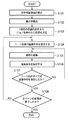
図5は描画命令の保存処理を示した図である。まず、ステップS101において、出力用紙における上下左右のマージンおよびとじ代部を除いた印刷可能領域を算出する。なお、前記とじ代部は印刷設定において、図7および図8に示すプリンタドライバの設定画面にて印刷者が設定を行うものとする。 FIG. 5 is a diagram showing a drawing command storing process. First, in step S101, the printable area excluding the top, bottom, left, and right margins and the binding margin in the output sheet is calculated. It should be noted that the binding margin section is set by the printer in print setting on the printer driver setting screen shown in FIGS.
次に、ステップS102において、前記ステップS101において算出した印刷可能領域より、とじ代を付加した場合における印刷データの縮小率を算出する。 Next, in step S102, the reduction rate of the print data when the binding margin is added is calculated from the printable area calculated in step S101.
縮小率が算出されると、処理はステップS103に移行し、ステップS103において1項目における印刷の向きの設定値から現在の印刷ジョブ全体のとじ位置を決定する。例えば、図2に示した印刷データおよび印刷設定の場合は、1項目のとじ位置と2項目のとじ位置を同じ位置にするため、図6に示したように2項目のとじ位置を長辺とじ(下)とする。 When the reduction ratio is calculated, the process proceeds to step S103, and the binding position of the entire current print job is determined from the set value of the print direction in one item in step S103. For example, in the case of the print data and print settings shown in FIG. 2, the binding position of one item and the binding position of two items are set to the same position, so that the binding position of two items is binding on the long side as shown in FIG. (Bottom).
そして、ステップS104において、前記ステップS102にて算出した縮小率を用いて、OSに対してページ全体の描画命令を要求する。ステップS105では、図7および図8に示した設定画面にて設定された値を使用し、出力用紙上に配置する位置を変更するために、OSを介してアプリケーションから渡された描画命令に含まれる座標情報を変更する。なお、前記ステップS105では、例えば、図4に示したように、長辺とじ(左)の場合は、とじ代設定画面にて指定した値だけ描画命令に含まれるX方向の座標情報を変更する。また、Y方向に関しては、印刷可能領域の上下に均等の余白が存在するようにY方向の座標情報も変更する。 Then, in step S104, a rendering command for the entire page is requested from the OS using the reduction ratio calculated in step S102. In step S105, the value set on the setting screen shown in FIGS. 7 and 8 is used, and is included in the drawing command passed from the application via the OS in order to change the position on the output paper. Change the coordinate information. In step S105, for example, as shown in FIG. 4, in the case of long-edge binding (left), the coordinate information in the X direction included in the drawing command is changed by the value specified on the binding margin setting screen. . For the Y direction, the coordinate information in the Y direction is also changed so that uniform margins exist above and below the printable area.
そして、ステップS106において、前記座標情報を変更した描画命令をハードディスクなどの一時記憶装置に保存する。その後、ステップS107において、現在のページに相当するすべての描画命令を保存したか否かを判断し、すべての描画命令の保存処理が終了していない場合は、ステップS105からステップS106までの処理を繰り返す。 In step S106, the drawing command whose coordinate information has been changed is stored in a temporary storage device such as a hard disk. Thereafter, in step S107, it is determined whether or not all drawing commands corresponding to the current page have been saved. If all drawing commands have not been saved, the processing from step S105 to step S106 is performed. repeat.
前記ステップS107において、すべての描画命令の保存処理が終了したと判断した場合は、ステップS108において、全ページの処理が終了したか否かの判断を行い、全ページの処理が終了していない場合は、ステップS104からS107までの処理を繰り返し、全ページの処理が終了した場合は、描画命令の保存処理を終了する。 If it is determined in step S107 that all drawing commands have been stored, it is determined in step S108 whether all pages have been processed, and all pages have not been processed. Repeats the processing from step S104 to step S107, and when the processing for all pages is completed, the drawing command storage processing is ended.
次に図9を用いて、保存した描画命令を使用して描画処理を行う処理の流れを説明する。 Next, the flow of a process for performing a drawing process using a saved drawing command will be described with reference to FIG.
ステップS201において、バンドメモリを取得および初期化し、ステップS202において、一時記憶装置に保存した描画命令を読み出し、ステップS203において、描画命令にて指示された描画オブジェクトをバンドメモリにビットマップ展開する描画処理を行う。 In step S201, the band memory is acquired and initialized. In step S202, the drawing command stored in the temporary storage device is read. In step S203, the drawing object designated by the drawing command is bitmap-developed in the band memory. I do.
次に、ステップS204において、現在のバンドに存在するすべての描画命令を処理したか否かの判断を行い、現在のバンドに存在するすべての描画命令の処理が終了していない場合は、ステップS202からS203までの処理を繰り返す。 Next, in step S204, it is determined whether all drawing commands existing in the current band have been processed. If processing of all drawing commands existing in the current band has not been completed, step S202 is performed. To S203 are repeated.
前記ステップS204において、現在のバンドに存在するすべての描画命令の処理が終了したと判断した場合は、ステップS205において、バンドメモリにRed・Green・Blueで示されたビットマップデータをCyan・Yellow・Magenta・Blackに色変換した後、多値のビットマップデータを量子化処理するなどのプリンタ用の色処理を施す。 If it is determined in step S204 that the processing of all drawing commands existing in the current band has been completed, the bitmap data indicated by Red, Green, and Blue is stored in the band memory in step S205. After color conversion to Magenta / Black, color processing for printers, such as quantizing multi-valued bitmap data, is performed.
そして、ステップS206では、前記ステップS205において作成されたデータがプリンタに転送される。 In step S206, the data created in step S205 is transferred to the printer.
ステップS207において、全バンドの処理が終了したか否かの判断を行い、全バンドの処理が終了していない場合は、ステップS202からS206までの処理を繰り返す。前記ステップS207において、全バンドの処理が終了したと判断された場合は、ステップS208において、全ページの処理が終了したか否かの判断を行い、全ページの処理が終了していない場合は、ステップS202からS207までの処理を繰り返し、全バンドの処理が終了した場合は描画処理を終了する。
<第2の実施形態>
第1の実施形態では、アプリケーションソフトウェアまたはオペレーティングシステムから渡される描画命令に含まれる座標情報を変換した後、描画命令をハードディスク等の一時記憶装置に保存する方式を示したが、座標情報を変換しない状態で描画命令をハードディスク等の一時記憶装置に保存した後、保存した描画命令をもとに描画処理を行う際に座標情報の変換処理を行う方式にも適用できる。
In step S207, it is determined whether or not the processing for all bands has been completed. If the processing for all bands has not been completed, the processing from steps S202 to S206 is repeated. If it is determined in step S207 that all the bands have been processed, it is determined in step S208 whether all pages have been processed. If all pages have not been processed, The processing from step S202 to S207 is repeated, and when the processing for all the bands is completed, the drawing processing is ended.
<Second Embodiment>
In the first embodiment, the coordinate information included in the drawing command passed from the application software or the operating system is converted, and then the drawing command is stored in a temporary storage device such as a hard disk. However, the coordinate information is not converted. The present invention can also be applied to a method in which after a drawing command is saved in a temporary storage device such as a hard disk in a state, coordinate information conversion processing is performed when drawing processing is performed based on the saved drawing command.
以下、図10および図11を参照して第2の実施形態における画像処理の流れを説明する。なお、画像処理すべき印刷データは、図1に示される関係にあり、この説明は第1の実施形態におけるものと同じなのでここでは省略する。 Hereinafter, the flow of image processing in the second embodiment will be described with reference to FIGS. 10 and 11. Note that the print data to be subjected to image processing has the relationship shown in FIG. 1, and the description thereof is the same as that in the first embodiment, and is omitted here.
まず、ステップS301において、出力用紙における上下左右のマージンおよびとじ代部を除いた印刷可能領域を算出する。なお、前記とじ代部は印刷設定において、図7および図8に示すプリンタドライバの設定画面にて印刷者が設定を行うものとする。 First, in step S301, the printable area excluding the top, bottom, left and right margins and the binding margin in the output sheet is calculated. It should be noted that the binding margin section is set by the printer in print setting on the printer driver setting screen shown in FIGS.
次に、ステップS302では、前記ステップS301において算出した印刷可能領域より、とじ代を付加した場合における印刷データの縮小率を算出する。 Next, in step S302, the reduction rate of the print data when the binding margin is added is calculated from the printable area calculated in step S301.
さらに、ステップS303にて1項目における印刷の向きの設定値から現在の印刷ジョブ全体のとじ位置を決定し、ハードディスクなどの一時記憶装置に保存する。 Further, in step S303, the binding position of the entire current print job is determined from the setting value of the print direction in one item, and is stored in a temporary storage device such as a hard disk.
そして、ステップS304において、前記ステップS302で算出された縮小率を用いて、OSに対してページ全体の描画命令を要求する。そしてステップS305において、描画命令をハードディスクなどの一時記憶装置に保存する。 In step S304, the OS requests the OS for a drawing command for the entire page using the reduction ratio calculated in step S302. In step S305, the drawing command is stored in a temporary storage device such as a hard disk.
その後、ステップS306において、現在のページに相当するすべての描画命令を保存したか否かを判断し、すべての描画命令の保存処理が終了していない場合は、ステップS305の処理を繰り返す。 Thereafter, in step S306, it is determined whether or not all drawing commands corresponding to the current page have been saved. If the saving processing for all drawing commands has not ended, the processing in step S305 is repeated.
前記ステップS306において、すべての描画命令の保存処理が終了したと判断した場合は、ステップS307において、全ページの処理が終了したか否かの判断が行われ、全ページの処理が終了していない場合は、ステップS304からS306までの処理を繰り返し、全ページの処理が終了した場合は、描画命令の保存処理を終了する。 If it is determined in step S306 that all drawing commands have been stored, it is determined in step S307 whether all pages have been processed, and all pages have not been processed. In this case, the processing from step S304 to S306 is repeated, and when the processing for all pages is completed, the drawing command storage processing is ended.
次に図11を用いて、保存した描画命令を使用して描画処理を行う処理の流れを説明する。 Next, the flow of a process for performing a drawing process using a saved drawing command will be described with reference to FIG.
ステップS401において、バンドメモリを取得および初期化する。 In step S401, the band memory is acquired and initialized.
ステップS402において、一時記憶装置に保存したとじ位置情報を読み出す。その後、ステップS403において、一時記憶装置に保存した描画命令を読み出し、ステップS404において、描画命令に含まれる座標情報を変更する。 In step S402, the binding position information stored in the temporary storage device is read. Thereafter, in step S403, the drawing command stored in the temporary storage device is read, and in step S404, the coordinate information included in the drawing command is changed.
そして、ステップS405において、描画命令で指示された描画オブジェクトをバンドメモリにビットマップ展開する描画処理を行う。その後、ステップS406において、現在のバンドに存在するすべての描画命令を処理したか否かの判断を行い、現在のバンドに存在するすべての描画命令の処理が終了していない場合は、ステップS403からS405までの処理を繰り返す。 Then, in step S405, a drawing process is performed in which the drawing object designated by the drawing command is bitmap-developed in the band memory. Thereafter, in step S406, it is determined whether or not all drawing commands existing in the current band have been processed. If processing of all drawing commands existing in the current band has not been completed, the process starts from step S403. The processing up to S405 is repeated.
前記ステップS406において、現在のバンドに存在するすべての描画命令の処理が終了したと判断した場合は、ステップS407において、バンドメモリにRed・Green・Blueで示されたビットマップデータをCyan・Yellow・Magenta・Blackに色変換した後、多値のビットマップデータを量子化処理するなどのプリンタ用の色処理を施す。 If it is determined in step S406 that the processing of all drawing commands existing in the current band has been completed, the bitmap data indicated by Red, Green, and Blue is stored in the band memory in step S407. After color conversion to Magenta / Black, color processing for printers, such as quantizing multi-valued bitmap data, is performed.
そして、ステップS408では、前記ステップS407において作成されたデータがプリンタに転送される。ステップS409において、全バンドの処理が終了したか否かの判断が行われ、全バンドの処理が終了していない場合は、ステップS403からS408までの処理が繰り返される。 In step S408, the data created in step S407 is transferred to the printer. In step S409, it is determined whether or not the processing for all bands has been completed. If the processing for all bands has not been completed, the processing from steps S403 to S408 is repeated.
前記ステップS409において、全バンドの処理が終了した場合は、ステップS410において、全ページの処理が終了したか否かの判断が行われる。全ページの処理が終了していない場合は、ステップS403からS409までの処理が繰り返され、全バンドの処理が終了した場合は描画処理を終了する。
なお、本発明は複数の機器(例えばホストコンピュータ、インタフェース機器、リーダ、プリンタなど)から構成されるシステムに適用しても、一つの機器からなる装置(例えば複写機、ファクシミリ装置など)に適用してもよい。
If the processing for all the bands is completed in step S409, it is determined in step S410 whether or not the processing for all pages is completed. If the processing for all pages has not been completed, the processing from step S403 to S409 is repeated, and if the processing for all bands has been completed, the drawing processing is terminated.
Note that the present invention can be applied to a system composed of a plurality of devices (for example, a host computer, an interface device, a reader, a printer, etc.) or an apparatus composed of a single device (for example, a copier, a facsimile machine, etc.). May be.
<第3の実施形態>
第1および第2の実施形態では、1項目における印刷の向きから現在の印字ジョブ全体のとじ位置を決定したが、印字ジョブ全体における各項の印刷の向きを判断し、印刷の向きが縦の項と印刷の向きが横の項を比較し、より多い項の印刷の向きを基準として、現在の印字ジョブ全体のとじ位置を決定する方式にも適用できる。
<Third Embodiment>
In the first and second embodiments, the binding position of the entire current print job is determined from the print direction of one item, but the print direction of each item in the entire print job is determined, and the print direction is vertical. The present invention can also be applied to a method in which a binding position of the entire current print job is determined by comparing a term and a term having a horizontal printing direction and using the printing direction of more terms as a reference.
また、本発明は、実施形態の機能を実現するソフトウェアのプログラムコードを記録した記憶媒体をシステム或は装置に提供し、そのシステム或は装置のコンピュータ(又はCPUやMPU)が記憶媒体に格納されたプログラムコードを読み出し実行することによっても達成される。この場合、記憶媒体から読み出されたプログラムコード自体が前述した実施形態の機能を実現することになり、そのプログラムコードを記憶した記憶媒体は本発明を構成することになる。このようなプログラムコードを供給するための記憶媒体としては、例えば、フロッピィ(登録商標)ディスク、ハードディスク、光ディスク、光磁気ディスク、CD−ROM、CD−R、磁気テープ、不揮発性のメモリカード、ROMなどを用いることができる。 In addition, the present invention provides a system or apparatus with a storage medium storing software program codes for realizing the functions of the embodiments, and the computer of the system or apparatus (or CPU or MPU) is stored in the storage medium. It is also achieved by reading and executing the program code. In this case, the program code itself read from the storage medium realizes the functions of the above-described embodiments, and the storage medium storing the program code constitutes the present invention. As a storage medium for supplying such a program code, for example, a floppy (registered trademark) disk, hard disk, optical disk, magneto-optical disk, CD-ROM, CD-R, magnetic tape, nonvolatile memory card, ROM Etc. can be used.
また、コンピュータが読み出したプログラムコードを実行することにより、前述した実施の形態の機能が実現されるだけでなく、そのプログラムコードの指示に基づき、コンピュータ上で稼動しているOS(オペレーティングシステム)などが実際の処理の一部又は全部を行い、その処理によって前述した実施の形態の機能が実現される場合も含まれている。 Further, by executing the program code read by the computer, not only the functions of the above-described embodiments are realized, but also an OS (operating system) running on the computer based on the instruction of the program code Includes a case where the function of the above-described embodiment is realized by performing part or all of the actual processing.
さらに、記憶媒体から読み出されたプログラムコードが、コンピュータに挿入された機能拡張ボードやコンピュータに接続された機能拡張ユニットに備わるメモリに書きこまれた後、そのプログラムコードの指示に基づき、その機能拡張ボードや機能拡張ユニットに備わるCPUなどが実際の処理の一部又は全部を行い、その処理によって前述した実施の形態の機能が実現される場合も含む。 Furthermore, after the program code read from the storage medium is written to the memory provided in the function expansion board inserted into the computer or the function expansion unit connected to the computer, the function is based on the instruction of the program code. This includes the case where the CPU of the expansion board or function expansion unit performs part or all of the actual processing, and the functions of the above-described embodiments are realized by the processing.
また、上記実施の形態の機能を実現するソフトウェアのプログラムコードがネットワークを介して配信されることにより、システム又は装置のハードディスクやメモリ等の記憶手段又はCD-RW、CD-R等の記憶媒体に格納され、そのシステム又は装置のコンピュータ(又はCPUやMPU)が当該記憶手段や当該記憶媒体に格納されたプログラムコードを読み出して実行することによっても、達成されることは云うまでもない。 Further, the program code of the software that realizes the functions of the above embodiments is distributed via a network, so that it can be stored in a storage means such as a hard disk or memory of a system or apparatus or a storage medium such as a CD-RW or CD-R Needless to say, this can also be achieved by the computer (or CPU or MPU) stored in the system or apparatus reading and executing the program code stored in the storage means or the storage medium.
本発明を上記記憶媒体に適用する場合、その記憶媒体には、先に説明した(図5、図9、図10、図11に示す)フローチャートに対応するプログラムコードが格納されることになる。 When the present invention is applied to the storage medium, the storage medium stores program codes corresponding to the flowcharts described above (shown in FIGS. 5, 9, 10, and 11).
<実施形態の効果>
以上の説明から明らかなように、本発明によれば、印刷の向きが横の場合に、印刷の向きが縦の場合に対して時計回りに90度回転して用紙に配置する描画処理装置あるいは描画処理方法において、印刷の向きととじ位置の関係が図1のようになっている場合でも、特定のページ(1ページ目)を基準に物理的なとじ位置を決定し、そのとじ位置に従ってとじ代を付加することによって、印刷ジョブ全体のとじ位置を統一して描画処理を行うことが可能になる。
<Effect of embodiment>
As is apparent from the above description, according to the present invention, when the printing direction is horizontal, the drawing processing apparatus rotates 90 degrees clockwise relative to the vertical printing direction and is arranged on the paper. In the drawing processing method, even when the relationship between the printing direction and the binding position is as shown in FIG. 1, the physical binding position is determined based on a specific page (first page), and the binding is performed according to the binding position. By adding the allowance, it is possible to perform the drawing process by unifying the binding position of the entire print job.
Claims (14)
印刷データに対するとじ代の位置および幅の入力を受け付ける受信手段と、
前記受け付けたとじ代部の領域から印刷可能領域を算出する領域算出手段と、
とじ代なしにおける印刷可能領域と前記算出したとじ代ありにおける印刷可能領域から、とじ代ありにおける前記印刷データの縮小率を算出する縮小率算出手段と、
1つの印刷ジョブ中に印刷の向きが縦・横混在したデータの場合に特定のページにおけるとじ位置を印刷ジョブ全体のとじ位置とするとじ位置設定手段と、
発行される描画命令に含まれる座標情報を変更する座標情報変更手段と、
前記座標変換した描画命令に基づいて描画処理を行う描画手段と、
を有することを特徴とする画像処理装置。 An image processing apparatus including a printer driver that generates print data by rotating 90 degrees clockwise with respect to a vertical print orientation when the print orientation is horizontal and arranging the print data on paper.
Receiving means for accepting input of a binding margin position and width for print data;
Area calculating means for calculating a printable area from the received binding margin area;
A reduction ratio calculating means for calculating a reduction ratio of the print data with a binding margin from a printable area without a binding margin and a printable area with the calculated binding margin;
A binding position setting means for setting the binding position on a specific page as the binding position of the entire print job in the case of data in which the printing orientation is mixed vertically and horizontally in one print job;
Coordinate information changing means for changing the coordinate information included in the issued drawing command;
A drawing means for performing a drawing process based on the coordinate-converted drawing command;
An image processing apparatus comprising:
印刷データに対するとじ代の位置および幅の入力を受け付ける受信工程と、
前記受け付けたとじ代部の領域から印刷可能領域を算出する領域算出工程と、
とじ代なしにおける印刷可能領域と前記算出したとじ代ありにおける印刷可能領域から、とじ代ありにおける縮小率を算出する縮小率算出工程と、
1つの印刷ジョブ中に印刷の向きが縦・横混在したデータの場合は特定のページにおけるとじ位置を印刷ジョブ全体のとじ位置とするとじ位置設定工程と、
発行される描画命令に含まれる座標情報を変更する座標情報変更工程と、
前記座標変更された描画命令に基づいて描画処理を行う描画工程と、
を有することを特徴とする画像処理方法。 An image processing method for generating print data by rotating 90 degrees clockwise with respect to a vertical print orientation when the print orientation is horizontal and arranging the print data on paper,
A receiving step for accepting input of a binding margin position and width for print data;
An area calculation step of calculating a printable area from the accepted binding margin area;
A reduction ratio calculating step of calculating a reduction ratio with a binding margin from a printable area without a binding margin and the calculated printable area with a binding margin;
In the case of data in which the orientation of printing is mixed vertically and horizontally in one print job, the binding position setting step for setting the binding position on a specific page as the binding position of the entire print job,
A coordinate information changing step for changing the coordinate information included in the issued drawing command;
A drawing step of performing a drawing process based on the drawing command whose coordinates have been changed;
An image processing method comprising:
A computer-readable storage medium storing the computer program according to claim 13.
Priority Applications (1)
| Application Number | Priority Date | Filing Date | Title |
|---|---|---|---|
| JP2004194289A JP2006019931A (en) | 2004-06-30 | 2004-06-30 | Apparatus and method for image processing, computer program, and storage medium |
Applications Claiming Priority (1)
| Application Number | Priority Date | Filing Date | Title |
|---|---|---|---|
| JP2004194289A JP2006019931A (en) | 2004-06-30 | 2004-06-30 | Apparatus and method for image processing, computer program, and storage medium |
Publications (2)
| Publication Number | Publication Date |
|---|---|
| JP2006019931A true JP2006019931A (en) | 2006-01-19 |
| JP2006019931A5 JP2006019931A5 (en) | 2007-01-25 |
Family
ID=35793785
Family Applications (1)
| Application Number | Title | Priority Date | Filing Date |
|---|---|---|---|
| JP2004194289A Pending JP2006019931A (en) | 2004-06-30 | 2004-06-30 | Apparatus and method for image processing, computer program, and storage medium |
Country Status (1)
| Country | Link |
|---|---|
| JP (1) | JP2006019931A (en) |
Cited By (4)
| Publication number | Priority date | Publication date | Assignee | Title |
|---|---|---|---|---|
| JP2008065367A (en) * | 2006-09-04 | 2008-03-21 | Sharp Corp | Information processing device, page image arrangement adjustment method, program, and recording medium |
| JP2012222711A (en) * | 2011-04-13 | 2012-11-12 | Seiko Epson Corp | Generating device of printing data, printer and method thereof |
| JP2012222712A (en) * | 2011-04-13 | 2012-11-12 | Seiko Epson Corp | Generating device of printing data, printer, and printing method |
| US9132632B2 (en) | 2011-03-24 | 2015-09-15 | Seiko Epson Corporation | Printing device and printing method |
-
2004
- 2004-06-30 JP JP2004194289A patent/JP2006019931A/en active Pending
Cited By (4)
| Publication number | Priority date | Publication date | Assignee | Title |
|---|---|---|---|---|
| JP2008065367A (en) * | 2006-09-04 | 2008-03-21 | Sharp Corp | Information processing device, page image arrangement adjustment method, program, and recording medium |
| US9132632B2 (en) | 2011-03-24 | 2015-09-15 | Seiko Epson Corporation | Printing device and printing method |
| JP2012222711A (en) * | 2011-04-13 | 2012-11-12 | Seiko Epson Corp | Generating device of printing data, printer and method thereof |
| JP2012222712A (en) * | 2011-04-13 | 2012-11-12 | Seiko Epson Corp | Generating device of printing data, printer, and printing method |
Similar Documents
| Publication | Publication Date | Title |
|---|---|---|
| US8194263B2 (en) | Technique to process a tint block image for restraining a material printed by a printing apparatus from being copied | |
| US20100153834A1 (en) | Business form creating system, network system using the same, and business form creating method | |
| US8014031B2 (en) | Formation of picture image having gradation expressed by fill area and one-line image data | |
| US8018618B2 (en) | Information processing apparatus that outputs images having same size to single page of recording sheet and computer readable medium | |
| JP4135195B2 (en) | Print processing system, print processing method, and computer-readable recording medium on which print processing control program is recorded | |
| JP4250470B2 (en) | Information processing apparatus, information processing method, and print control program | |
| JP2010130463A (en) | Print data generation apparatus, printing device, and print data processing system | |
| JP2008077160A (en) | Image processing device, image processing method, image forming apparatus, computer-executable program, and recording medium storing the program | |
| JP5063501B2 (en) | Image forming apparatus, control method, and control program | |
| JP4560570B2 (en) | Information processing apparatus, information processing method, and print control program | |
| JP2006019931A (en) | Apparatus and method for image processing, computer program, and storage medium | |
| JP6330790B2 (en) | Print control system, print control apparatus, and program | |
| JP2004106192A (en) | Writing processor, information processor, image formation apparatus, writing processing method and program | |
| US7869097B2 (en) | Print controlling program and print system for transparent-printing second print data in superposition on first print data | |
| JP2006165863A (en) | Information processing system | |
| JP2005182694A (en) | Layout printing system | |
| JP4998421B2 (en) | Image forming apparatus and image forming program | |
| JP2011197956A (en) | Printer control device, and printer apparatus and control method thereof | |
| JP6507809B2 (en) | Printing instruction device, printing system and program | |
| JP6107181B2 (en) | Printing program, printing apparatus, and printing method | |
| JP4685047B2 (en) | Image processing apparatus, image processing method, and image processing program | |
| JP2004220327A (en) | Printing system | |
| JP2009134758A (en) | Printing controller, print area information generating device, arrangement specifying data structure, print control method, print area information generation method, printing control program and print area information generating program | |
| JP5776145B2 (en) | Image processing apparatus, image processing method, program, and recording medium | |
| JP2006087042A (en) | Image processing apparatus |
Legal Events
| Date | Code | Title | Description |
|---|---|---|---|
| A521 | Request for written amendment filed |
Free format text: JAPANESE INTERMEDIATE CODE: A523 Effective date: 20061205 |
|
| A621 | Written request for application examination |
Free format text: JAPANESE INTERMEDIATE CODE: A621 Effective date: 20061205 |
|
| A977 | Report on retrieval |
Free format text: JAPANESE INTERMEDIATE CODE: A971007 Effective date: 20080117 |
|
| A131 | Notification of reasons for refusal |
Free format text: JAPANESE INTERMEDIATE CODE: A131 Effective date: 20080201 |
|
| A02 | Decision of refusal |
Free format text: JAPANESE INTERMEDIATE CODE: A02 Effective date: 20080606 |