JP4142601B2 - Fixing apparatus and driving method thereof - Google Patents
Fixing apparatus and driving method thereof Download PDFInfo
- Publication number
- JP4142601B2 JP4142601B2 JP2004061141A JP2004061141A JP4142601B2 JP 4142601 B2 JP4142601 B2 JP 4142601B2 JP 2004061141 A JP2004061141 A JP 2004061141A JP 2004061141 A JP2004061141 A JP 2004061141A JP 4142601 B2 JP4142601 B2 JP 4142601B2
- Authority
- JP
- Japan
- Prior art keywords
- roller
- speed
- roller body
- layer
- heating roller
- Prior art date
- Legal status (The legal status is an assumption and is not a legal conclusion. Google has not performed a legal analysis and makes no representation as to the accuracy of the status listed.)
- Expired - Fee Related
Links
Images


Classifications
-
- G—PHYSICS
- G03—PHOTOGRAPHY; CINEMATOGRAPHY; ANALOGOUS TECHNIQUES USING WAVES OTHER THAN OPTICAL WAVES; ELECTROGRAPHY; HOLOGRAPHY
- G03G—ELECTROGRAPHY; ELECTROPHOTOGRAPHY; MAGNETOGRAPHY
- G03G15/00—Apparatus for electrographic processes using a charge pattern
- G03G15/20—Apparatus for electrographic processes using a charge pattern for fixing, e.g. by using heat
- G03G15/2003—Apparatus for electrographic processes using a charge pattern for fixing, e.g. by using heat using heat
- G03G15/2014—Apparatus for electrographic processes using a charge pattern for fixing, e.g. by using heat using heat using contact heat
- G03G15/2064—Apparatus for electrographic processes using a charge pattern for fixing, e.g. by using heat using heat using contact heat combined with pressure
-
- G—PHYSICS
- G03—PHOTOGRAPHY; CINEMATOGRAPHY; ANALOGOUS TECHNIQUES USING WAVES OTHER THAN OPTICAL WAVES; ELECTROGRAPHY; HOLOGRAPHY
- G03G—ELECTROGRAPHY; ELECTROPHOTOGRAPHY; MAGNETOGRAPHY
- G03G15/00—Apparatus for electrographic processes using a charge pattern
- G03G15/20—Apparatus for electrographic processes using a charge pattern for fixing, e.g. by using heat
- G03G15/2003—Apparatus for electrographic processes using a charge pattern for fixing, e.g. by using heat using heat
- G03G15/2014—Apparatus for electrographic processes using a charge pattern for fixing, e.g. by using heat using heat using contact heat
- G03G15/206—Structural details or chemical composition of the pressure elements and layers thereof
-
- G—PHYSICS
- G03—PHOTOGRAPHY; CINEMATOGRAPHY; ANALOGOUS TECHNIQUES USING WAVES OTHER THAN OPTICAL WAVES; ELECTROGRAPHY; HOLOGRAPHY
- G03G—ELECTROGRAPHY; ELECTROPHOTOGRAPHY; MAGNETOGRAPHY
- G03G2215/00—Apparatus for electrophotographic processes
- G03G2215/20—Details of the fixing device or porcess
- G03G2215/2003—Structural features of the fixing device
- G03G2215/2048—Surface layer material
- G03G2215/2051—Silicone rubber
Description
本発明は、例えば、画像形成装置に用いられる定着装置に関する。 The present invention relates to a fixing device used in, for example, an image forming apparatus.
この種の定着装置には円筒型の剛体を有し、この剛体の外側に低熱伝導性材料からなる層、導電性材料からなる導電体層、及び離型層を順次、積層してなる定着ローラを備えるとともに、この定着ローラの近傍にその外周面に対向して誘導加熱源を設け、この誘導加熱源により定着ローラの導電体層を誘導加熱することにより、定着ローラを短時間で所望する温度に加熱できるようにしたものがある(例えば、特許文献1参照。)。 This type of fixing device has a cylindrical rigid body, and a fixing roller formed by sequentially laminating a layer made of a low thermal conductivity material, a conductor layer made of a conductive material, and a release layer on the outside of the rigid body. In addition, an induction heating source is provided in the vicinity of the fixing roller so as to oppose the outer peripheral surface thereof, and the conductive layer of the fixing roller is induction-heated by the induction heating source, whereby the fixing roller is heated to a desired temperature in a short time. (For example, refer to Patent Document 1).
また、この種の定着装置には、中空部材上に導電層を形成してなる加熱部材と、この加熱部材の外側に配置され導電層に変動磁界を発生させる磁界発生手段とを備えてなり、短時間でウォームアップできるようにしたものもある(例えば、特許文献2参照。)。 In addition, this type of fixing device includes a heating member formed with a conductive layer on a hollow member, and a magnetic field generating unit that is disposed outside the heating member and generates a variable magnetic field in the conductive layer. There are some which can be warmed up in a short time (see, for example, Patent Document 2).
さらに、この種の定着装置には、加熱ローラと加圧ローラとのニップ部以外の周面を囲むようにリッツ線により構成した導線を配置し、この導線を高周波発振部に接続して高周波電流を印加することにより加熱ローラの表面を加熱するものがある。この定着装置は、加熱ローラの表面を直接加熱するため、エネルギー損失が少なく、かつ立ち上がり時間の短縮が可能となっている(例えば、特許文献3参照。)。
しかしながら、従来においては、実用にあたって発生すると考えられる以下のような問題についての考慮が無かった。 However, conventionally, there has been no consideration for the following problems that are considered to occur in practical use.
1.長期間にわたる使用などが理由の劣化等による、定着ローラの構成要素である各層の破壊や層間剥離などが起こった時の対処。 1. What to do when damage or delamination of each layer, which is a component of the fixing roller, occurs due to deterioration due to long-term use, etc.
2.各層間に滑りが発生した時の対処。 2. What to do when slipping occurs between each layer.
3.定着ローラが変形したときの用紙剥離用のブレードの位置決めに関する考慮。 3. Consideration regarding positioning of blade for peeling paper when fixing roller is deformed.
4.加熱回転体と加圧回転体の両方に弾性体層上に導体層を持つ回転体を用いた場合において双方の材料や層厚を変えることによる、ローラ硬度及び熱伝導率、熱容量の調整と、それによる剥離性、定着性、ウォームアップ時間の改善。 4). Adjustment of roller hardness, thermal conductivity, and heat capacity by changing both materials and layer thickness in the case of using a rotating body having a conductor layer on an elastic layer as both a heating rotating body and a pressure rotating body, This improves the peelability, fixability and warm-up time.
本発明は上記事情に着目してなされたもので、実用にあたって発生すると考えられる問題に対する対策と、加熱回転体、加圧回転体の両方、又は片方に弾性体層上に導体層を持つ回転体を用いた場合に有効に利用できる定着装置を提供することを目的とする。 The present invention has been made by paying attention to the above circumstances, and measures against problems considered to occur in practical use, both a heating rotator and a pressure rotator, or a rotator having a conductor layer on an elastic layer on one side. It is an object of the present invention to provide a fixing device that can be used effectively when using the printer.
この発明は、上記課題を解決するため、芯材と、この芯材の外側に形成された外周層と、を有する第1のローラ体と、この第1のローラ体とニップ部を形成する第2のローラ体と、前記第1のローラ体を回転させる駆動手段と、この駆動手段から前記第1のローラ体に付与される回転数に基いて、前記第1のローラ体の外周層の周速を計算する速度算出手段と、前記第1のローラ体の外周層の周速を検出する速度検出手段と、前記速度算出手段により計算された前記第1のローラ体の周速と前記速度検出手段により検出された前記第1のローラ体の周速に差がある場合、前記駆動手段の動作を停止する制御手段と、を有することを特徴とする定着装置を提供するものである。 In order to solve the above problems, the present invention provides a first roller body having a core material and an outer peripheral layer formed on the outer side of the core material, and a first roller body and a first nip portion that forms a nip portion. and second roller body, and driving means for rotating the first roller body, on the basis of the rotational speed applied to the first roller member from the driving means, perimetric layer of the first roller body a speed calculation means for calculating the speed, the first speed detecting means for detecting the peripheral speed of the peripheral layer of the roller member, said speed detection and the peripheral speed of the first roller body calculated by said speed calculating means And a control unit that stops the operation of the driving unit when there is a difference in the peripheral speed of the first roller body detected by the unit .
またこの発明は、上記課題を解決するため、芯材の外側に少なくとも1つの外周層が形成されている第1のローラ体と、第1のローラ体とニップ部を形成する第2のローラ体と、第1のローラ体を回転させる駆動手段と、を有する定着装置において、駆動手段により第1のローラ体へ供給される駆動力に基づき、速度算出手段により第1のローラ体の外周層の周速を求め、第1のローラ体の外周層の実際の周速度を、速度検出装置により検出し、速度算出手段により求められた周速と速度検出装置により検出された周速とに差が存在する場合、駆動手段を停止することを特徴とする定着装置の駆動方法である。 In order to solve the above-described problems, the present invention provides a first roller body in which at least one outer peripheral layer is formed outside the core material, and a second roller body that forms a nip portion with the first roller body. And a driving means for rotating the first roller body, and based on the driving force supplied to the first roller body by the driving means, the speed calculation means determines the outer peripheral layer of the first roller body. The peripheral speed is obtained, the actual peripheral speed of the outer peripheral layer of the first roller body is detected by the speed detecting device, and there is a difference between the peripheral speed obtained by the speed calculating means and the peripheral speed detected by the speed detecting device. If present, the driving means is stopped, and the fixing device driving method is characterized in that the driving means is stopped .
本発明によれば、実用にあたって発生すると考えられる問題に対する対策と、加熱回転体、加圧回転体の両方、又は片方に弾性体層上に導体層を持つ回転体を用いた場合に有効に利用できる定着装置、すなわち加熱回転体である第1のローラ体、加圧回転体である第2のローラ体の両方、又は片方に少なくとも弾性体層または導体層を持つ回転体であるローラ体を用いた定着装置において生じることのある、長期間にわたる使用などが理由の劣化等による、各ローラ体の構成要素である各層の破壊や層間剥離などが起こった時に、有効な対応ができる。 According to the present invention, it is effectively used when a rotating body having a conductor layer on an elastic body layer is used as a countermeasure against problems considered to occur in practical use, both of a heating rotating body and a pressing rotating body, or one of them. Fixing device, that is , a first roller body that is a heating rotator , a second roller body that is a pressure rotator, or a roller body that is a rotator having at least an elastic layer or a conductor layer on one side. may be caused Oite the fixing equipment which had, used such as by deterioration of the reasons long-term, when the destruction and delamination of the layers has occurred is a component of the the roller body, it is valid corresponding.
以下、本発明を図面に示す実施の形態を参照して詳細に説明する。
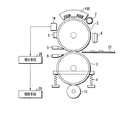
図1は、本発明の第1の実施の形態である定着装置1を全体的に示す概略的構成図である。
Hereinafter, the present invention will be described in detail with reference to embodiments shown in the drawings.
FIG. 1 is a schematic configuration diagram generally showing a fixing device 1 according to a first embodiment of the present invention.
定着装置1は、画像形成装置に備えられ、加熱回転体としての加熱(ヒート)ローラ2(φ40mm)と、加圧回転体としての加圧(プレス)ローラ3(φ40)を備えた構成となっている。加熱ローラ2としては図2に示すようなエンドレス部材11を用いている。エンドレス部材11の詳しい構成については後で述べる。
The fixing device 1 is provided in an image forming apparatus and includes a heating (heat) roller 2 (φ40 mm) as a heating rotator and a pressure (press) roller 3 (φ40) as a pressure rotator. ing. An
加圧ローラ3は芯材の周囲にシリコンやフッ素などのゴムを被覆して構成されている。加圧ローラ3は加圧機構4によって前記加熱ローラ2に対して圧接され、一定のニップ幅を持つように維持されている。加熱ローラ2は駆動モータ21により矢印方向に駆動され、加圧ローラ3は従動で矢印方向に回転するようになっている。
The
加熱ローラ2の上部側には、磁束発生用のコイル100が設けられ、加熱ローラ2はこの磁束発生用のコイル100からの磁束を受けて発熱する。これら加熱ローラ2と加圧ローラ3との圧接部(ニップ部)である定着ポイントを用紙22が通過することで、この用紙22上の現像剤像22aを融着圧着して定着するようになっている。
A
加熱ローラ2の周囲部にはその回転方向に亘って、剥離爪5、サーミスタ6、クリーニング部材7、およびサーモスタッド8が配設されている。剥離爪5は用紙22を加熱ローラ2から剥離させるものである。サーミスタ6は加熱ローラ2の長手方向に複数配設され、加熱ローラ2の温度検出をするものである。このサーミスタ6の検出温度に基づいて図示しない温度制御装置により加熱ローラ2の温度を調節するようになっている。
A
クリーニング部材7は加熱ローラ2上にオフセットされたトナーや紙屑等のごみを除去するものである。サーモスタッド8は加熱ローラ2上に少なくても1つ以上設けられ、加熱ローラ2の表面温度の異常を検出して加熱を遮断するものである。加圧ローラ3の周囲部には、用紙22を加圧ローラ3から剥離するための剥離爪9、トナーを除去するためのクリーニングローラ10が設けられている。
The
図2は、加熱ローラ2を構成するエンドレス部材11を示す断面図である。
FIG. 2 is a cross-sectional view showing the
エンドレス部材11は芯材16を有し、この芯材16上に順次、弾性体層12、導体層13、弾性体層14、及び離型層15を積層して構成されている。弾性体層12は例えばシリコンゴム又は発泡ゴムにより形成され、導体層13は例えばニッケルにより形成されている。弾性体層14は、例えばシリコンゴムにより形成され、離型層15は例えばPFAにより形成されている。
The
このような構成にすることで、導体層13を誘導加熱し、エンドレス部材11の表面近くで発熱させることができるため、エネルギー効率がよく、加熱装置の早い立ち上がりを期待できる。
With such a configuration, the
また、導体層13や弾性体層12、14の層厚や材料の硬度を調節することでエンドレス部材11の硬度を調節でき、ニップ幅や剥離性能を調整できるメリットも併せ持つ。
In addition, the hardness of the
本実施の形態では、弾性体層12としては厚さ4.73mmの発泡ゴム、導体層13としては厚さ40μmのニッケル、弾性体層14として厚さ200μmのシリコンゴムを用いている。離型層15としては、厚さ30μmのPFAを用い、芯材16として厚さ1.5mmの鉄を用いている。
In the present embodiment, foamed rubber having a thickness of 4.73 mm is used as the
そして、弾性体層12と導体層13の境界、及び導体層13と弾性体層14の境界は、それぞれ耐熱温度200℃以上の耐熱接着剤25,26により接着されている。
The boundary between the
定着時には加熱ローラ2の表面は、約200℃程度まで加熱される。また、加熱ローラ2、加圧ローラ3は用紙搬送の役わりも持っており、定着時には各層が互いに滑らないように各層12,13,14同士を固定する必要がある。これらのことから、各層12,13,14同士の固定には耐熱温度200℃以上の耐熱接着剤25,26が用いられている。
At the time of fixing, the surface of the
この実施の形態によれば、各層12,13,14の滑り、剥離を防止することができる。
According to this embodiment, it is possible to prevent the
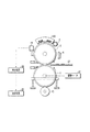
図3は、本発明の第2の実施の形態である定着装置を示すものである。 FIG. 3 shows a fixing device according to a second embodiment of the present invention.
なお、上記した第1の実施の形態で示した部分と同一部分については、同一符号を付してその説明を省略する。 The same parts as those shown in the first embodiment are denoted by the same reference numerals and the description thereof is omitted.
上記加熱ローラ2には、サーミスタ6より加熱ローラ2の回転方向下流側に位置して検出ローラ17が当接され、この検出ローラ17は、図示しない押圧機構により加熱ローラ2に押圧されている。なお、検出ローラ17はサーミスタ6より加熱ローラ2の回転方向上流側に位置して設けても問題はない。
A
検出ローラ17の回転軸には例えばエンコーダ(図示しない)が取り付けられており、検出ローラ17の角速度を検出手段28で検出できるようになっている。加熱ローラ2が芯材16に駆動力を受けることにより回転する際、検出ローラ17もそれに従動して回転し、検出ローラ17の周速と加熱ローラ2の周速は同じになる。
For example, an encoder (not shown) is attached to the rotation shaft of the
従って、検出ローラ17の半径を予め知っておき、その角速度を検出することで速度検出ローラ17の周速を計算し、加熱ローラ2の周速を知ることができる。本実施例では速度検出ローラ17は加熱ローラ2のクリーニングローラも兼ねている。
Therefore, by knowing the radius of the
図4〜図6は加熱ローラ2の周速を検出するための他の例を示すものである。
4 to 6 show other examples for detecting the peripheral speed of the
この例では、図4に示すように加熱ローラ2の表面が撮影可能な位置に近接対向して例えばフォトカプラなどの光読取素子18を設置している。そして、図5に示すように、加熱ローラ2の表面の一部に加熱ローラ2の表面の色とは異なる色のライン2Aを形成し、或いは図6に示すようにマーク2Bを形成する。
In this example, as shown in FIG. 4, an
加熱ローラ2の回転時にそのライン2A或いはマーク2Bを光読取素子18によって読み取ることにより、加熱ローラ2の角速度を検出して、加熱ローラ2の半径との関係からその周速を計算する。
When the
この実施の形態では加熱ローラ2の周速を検出しているが、加圧ローラ3についても同様の方法で周速を検出できることは言うまでもない。
In this embodiment, the peripheral speed of the
この実施の形態で用いているエンドレス部材11は機械的強度の異なる複数の層12,13,14で構成されており、比較的強度の弱い弾性体層12,14の破壊や層間剥離が予想される。そのような部材の破壊を検出するために本実施例で用いている画像形成装置には上記速度検出手段を用いた自己診断ルーチンが搭載されている。
The
図7は、自己診断ルーチンを示すフローチャートである。 FIG. 7 is a flowchart showing a self-diagnosis routine.
この自己診断ルーチンでは、まず、加熱ローラ2の芯材16に負荷されている駆動力による回転速度(角速度)と加熱ローラ2の半径の関係から加熱ローラ2の周速Aを計算して求める(ステップST1)。これと同時に上記のように速度検出ローラ17を用いて加熱ローラ2の周速Bを検出する(ステップST2)。
In this self-diagnosis routine, first, the peripheral speed A of the
ついで、周速A,Bの値の大小関係を判定するためにその差A−Bを求める(ステップST3)。 Next, in order to determine the magnitude relationship between the values of the peripheral speeds A and B, a difference A−B is obtained (step ST3).
これら周速A、Bは加熱ローラ2に破壊がない場合には同じになる。加熱ローラ2に破壊がある場合には、破壊した部分で回転の滑りが生じ、破壊部分より外側の部分は内側の部分の回転速度より遅い速度で回転、もしくはまったく回転しない状態になる。
These peripheral speeds A and B are the same when the
そのため、ローラ周速Bはローラ周速Aより遅くなる。このことからA−B>0となった場合にはローラ2が破壊していると判断する(ステップST4)。この場合には、制御手段29により画像形成装置の運転を停止し、故障が生じていること、部品の交換が必要であることをユーザーやサービスマンなどに知らせるために、例えば画像形成装置本体の操作部の表示パネルにその旨を表示する。この自己診断ルーチンは速度検出対象の加熱ローラ2が回転しているときには常に働いている。
Therefore, the roller circumferential speed B is slower than the roller circumferential speed A. From this, when A-B> 0, it is determined that the
この実施の形態では周速A,Bの値の比較のために速度差を用いたが、これに限られず速度比なども用いることができ、周速A、Bの値の大小が比較できれば比較方法は何でも良い。 In this embodiment, the speed difference is used to compare the values of the peripheral speeds A and B. However, the speed ratio is not limited to this, and if the values of the peripheral speeds A and B can be compared, the comparison is possible. Any method is acceptable.
また、自己診断ルーチンにより加熱ローラ2の破壊が検出された際に、本実施例では画像形成装置を停止させているが、定着装置1のみ、或いは加熱ローラ2の回転のみ、または、加熱のみを停止させても良い。
Further, in the present embodiment, when the breakage of the
また、この実施の形態では、自己診断ルーチンは、速度検出対象のローラが回転しているときには常に働いているとしたが、画像形成装置が稼動中は常に働いているとしても良く、自己診断ルーチンがいつ働いているかにより本発明の範囲を限定することはない。 In this embodiment, the self-diagnosis routine always works when the speed detection target roller rotates. However, the self-diagnosis routine may always work while the image forming apparatus is operating. The scope of the present invention is not limited by when is working.
図8は、本発明の第3の実施の形態である定着装置を示す構成図である。 FIG. 8 is a configuration diagram showing a fixing device according to a third embodiment of the present invention.
なお、上記した第1の実施の形態で示した部分と同一部分については、同一符号を付してその説明を省略する。 The same parts as those shown in the first embodiment are denoted by the same reference numerals and the description thereof is omitted.
第2の実施の形態では、加熱ローラ2に駆動力を付与して回転させ、それに加圧ローラ3を従動させて回転させたが、この第3の実施の形態では、加圧ローラ3に対して駆動モータ31により回転力を付与して回転させ、それに加熱ローラ2を従動回転させる。
In the second embodiment, the
この加熱ローラ2の周速Dを第2の実施の形態と同様の方法で検出する。詳細は省略する。そして、本実施例で用いている画像形成装置には従動して回転する加熱ローラ2と加圧ローラ3の間の滑りを検出する滑り検出ルーチンを備えている。
The peripheral speed D of the
図9は滑り検出ルーチンを示すフローチャート図である。図15の回路と合わせて、この滑り検出ルーチンを以下に説明する。 FIG. 9 is a flowchart showing a slip detection routine. This slip detection routine will be described below in conjunction with the circuit of FIG.
この滑り検出ルーチンでは、定着装置の駆動が開始されると、速度比較回路50はROM51から加熱ローラ2及び加圧ローラ3の速度差許容値Eを読み出す(ST11)。その後、加圧ローラ3に付加されている駆動力を加圧ローラ駆動手段52から読み出し、回転速度(角速度)とローラ3の半径との関係から加圧ローラの周速度Cを求める(ST12)。ついで、検出手段53により加熱ローラ2の周速Dを検出する(ステップ13)。
In this slip detection routine, when the driving of the fixing device is started, the
次に、これらC,Dの値の大小関係を判定するためにその差C−Dを求め、その誤差を許容値Eと比較する(ST14)。上記差が許容値E以上であれば、ローラ2,3間で滑りが発生していると判断し、許容値E以内であれば、滑りは発生していないと判断する(ST15)。
Next, in order to determine the magnitude relationship between the values of C and D, a difference CD is obtained, and the error is compared with an allowable value E (ST14). If the difference is equal to or greater than the allowable value E, it is determined that slip has occurred between the
この場合には、画像形成装置の運転を停止し、故障が生じていることをユーザーやサービスマンなどに知らせるために、例えば画像形成装置本体の操作部の表示パネルにその旨を表示する。この滑り検出ルーチンは速度検出対象のローラが回転しているときには常に働いている。 In this case, in order to stop the operation of the image forming apparatus and notify the user, service person, or the like that a failure has occurred, this fact is displayed, for example, on the display panel of the operation unit of the image forming apparatus main body. This slip detection routine always works when the speed detection target roller is rotating.
この実施の形態では周速C,Dの値の比較のために速度差を用いたが、他にも速度比なども用いることができ、C、Dの値の大小が比較できれば比較方法は何でも良い。 In this embodiment, the speed difference is used to compare the values of the peripheral speeds C and D. However, a speed ratio or the like can also be used, and any comparison method can be used as long as the values of C and D can be compared. good.
また、滑り検出ルーチンによりローラ2,3間の滑りが検出された際に、本実施例では画像形成装置を停止させているが、定着装置のみ、或いは加熱装置のみを停止させても良い。
Further, in this embodiment, when the slip between the
さらに、この実施の形態では滑り検出ルーチンは、速度検出対象のローラが回転しているときには常に働いているとしたが、画像形成装置が稼動中は常に働いているとしても良く、滑り検出ルーチンがいつ働いているかにより本発明の範囲を限定することはない。 Further, in this embodiment, the slip detection routine is always working when the speed detection target roller is rotating. However, the slip detection routine may be always working while the image forming apparatus is operating. It does not limit the scope of the invention depending on when it works.
また、本実施例では加圧ローラ3に駆動力を付加し、加熱ローラ2の周速を速度検出手段により検出したが、加熱ローラ2に駆動力を付加し、上記と同様の方法で加圧ローラ3の周速を検出することや、その値を用いて滑り検出を行うことは当然可能である。
In this embodiment, a driving force is applied to the
この滑り検出ルーチンでは駆動力が付加されているローラの破壊によるローラの回転不良も検出できる。加圧ローラに上記エンドレス部材11を用いた場合にも滑り検出ルーチンが使用可能であることは言うまでも無い。
In this slip detection routine, it is possible to detect a rotation failure of the roller due to the breakage of the roller to which the driving force is applied. Needless to say, the slip detection routine can also be used when the
図10は、本発明の第4の実施の形態である定着装置を示すものである。 FIG. 10 shows a fixing device according to a fourth embodiment of the present invention.
なお、上記した第1の実施の形態で示した部分と同一部分については、同一符号を付してその説明を省略する。 The same parts as those shown in the first embodiment are denoted by the same reference numerals and the description thereof is omitted.
この実施の形態では、加熱ローラ2にエンドレス部材11を用い、加圧ローラ3は芯材33の周囲にシリコンやフッ素などのゴム層34を被覆して構成されている。加熱ローラ2側の弾性層12の厚さは4.73mm、加圧ローラ3側のゴム層34の厚さは2mmとされ、加熱ローラ2の厚さが厚く、表面硬度が柔らかくされている。
In this embodiment, the
このような構成にすることで定着後の加熱ローラ2からの用紙Pの剥離性が良くなることが期待できる。
With such a configuration, it can be expected that the peelability of the paper P from the
この実施の形態ではゴム層12,34の厚さを変えることで加熱ローラ2の硬度を加圧ローラ3の硬度より柔らかくしたが、ゴムの材質を加熱ローラ2の方が加圧ローラ3より柔らかいものにすることで加熱ローラ2の硬度を加圧ローラ3の硬度より柔らかくしても良い。
In this embodiment, the hardness of the
図11は、本発明の第5の実施の形態である定着装置を示す構成図である。 FIG. 11 is a configuration diagram showing a fixing device according to a fifth embodiment of the present invention.
エンドレス部材11が柔らかく変形し易いものであることや、長期間にわたる使用での変形、加熱時の熱膨張による変形が予想以上に大きくなることが考えられる。
It is conceivable that the
従って、第1の実施の形態の装置構成だと加熱ローラ2側の剥離爪5がローラ2の変形によりローラ2の表面から離れたり、ローラ2に予想以上に強く押し付けられ、意図したとおりに機能しないことが考えられる。
Therefore, in the apparatus configuration of the first embodiment, the peeling
そこで、この実施の形態では、調整手段40により剥離ブレード20を保持するとともに、その両端部に位置決めローラ19,19を取り付け、これら位置決めローラ19,19を加熱ローラ2の表面に図示しない押圧機構により当接させている。これにより、図12に示すように位置決めローラ19,19によって位置決めされた剥離ブレード20と加熱ローラ2との間の距離が常に一定に保持され、定着後の用紙22を剥離する。
Therefore, in this embodiment, the
剥離ブレード20の方向は図示しないガイドによって固定されている。図中のEは剥離ブレード20の有効な範囲であり、その長さは310mmと用紙22の幅より広くされている。
The direction of the
このような構成にすることで加熱ローラ2が変形した場合にも位置決めローラ19,19がその変形に追従し、ローラ2と剥離ブレード20との間の距離を一定に保ち、剥離ブレード20を有効に機能させることができる。
With this configuration, even when the
なお、この実施の形態では、剥離ブレード20を用いたが、同様の方法で剥離爪を用いても良い。
In this embodiment, the
図13は本発明の第6の実施の形態を示すものである。 FIG. 13 shows a sixth embodiment of the present invention.
なお、上記した第1の実施の形態で示した部分と同一部分については同一符号を付してその説明を省略する。 In addition, the same code | symbol is attached | subjected about the part same as the part shown in the above-mentioned 1st Embodiment, and the description is abbreviate | omitted.
この実施の形態では、加圧ローラ3に上記エンドレス部材11を用い、加熱ローラ2は芯材37の周囲にシリコンやフッ素などのゴム層38を被覆して構成されている。加圧ローラ3側の弾性層12の厚さは4.73mmで、加熱ローラ2側のゴム層38の厚さは10mmと厚くされ、加熱ローラ2の表面硬度が柔らかくされている。
In this embodiment, the
このように、用紙上に形成されたトナーの溶融が行われる加熱ローラの硬度を加圧ローラの硬度よりも高くすることで定着後の加熱ローラ2からの用紙の剥離性が良くなることが期待できる。
In this way, it is expected that the releasability of the paper from the
本実施例ではゴム層38の厚さを変えることで加熱ローラ2の硬度を加圧ローラ3の硬度より柔らかくしたが、ゴムの材質を加熱ローラ2の方が加圧ローラ3より柔らかいものにすることで加熱ローラ2の硬度を加圧ローラ3の硬度より柔らかくしても良い。
In this embodiment, the hardness of the
図14は、本発明の第7の実施の形態である定着装置を示すものである。 FIG. 14 shows a fixing device according to a seventh embodiment of the present invention.
なお、上記した第1の実施の形態で示した部分と同一部分については同一符号を付してその説明を省略する。 In addition, the same code | symbol is attached | subjected about the part same as the part shown in the above-mentioned 1st Embodiment, and the description is abbreviate | omitted.
この第7の実施の形態では、加熱ローラ2と加圧ローラ3とが略同様に構成され、その弾性体層12の材料のみが異なる。加熱ローラ2側の弾性体層12の材料にはASKER−C硬度が10°の発泡ゴムが用いられ、加圧ローラ3側の弾性体層12の材料にはASKER−C硬度が40°の発泡ゴムが用いられている。即ち、加圧ローラ3の硬度が加熱ローラ2の硬度よりも高くなるように構成されている。このような構成にすることで、定着後の用紙22が確実に加熱ローラ2から剥離できるようにする。
In the seventh embodiment, the
この実施の形態では、弾性体層12のみの材料を異ならせることでローラ硬度を異ならせたが、弾性体層12、導体層13、弾性体層14、離型層15、芯材16等の全ての構成要素について、材料及び厚さを2つのローラ2,3間で互いに異ならせても良い。
In this embodiment, the roller hardness is changed by changing the material of only the
このようにして、上記エンドレス部材の構成要素の材料、厚さを2つのローラ2,3間で互いに異ならせてローラ2,3の硬度や熱伝導率を変化させ、設計者がある程度の範囲で自由に設定できるため、定着装置の定着性能や加熱時の昇温速度、熱容量の調整ができ、また、用紙の剥離性能の向上を図ることができる。
In this way, the materials and thicknesses of the constituent elements of the endless member are made different between the two
なお、上記した各実施の形態では、加熱ローラ2のみを誘導加熱で加熱したが、磁束発生コイル100を加圧ローラ3側にも設置することや、両方のローラ2,3を加熱できる位置に磁束発生コイル100を設置することで加圧ローラ3も同時に加熱することも可能である。
In each of the above-described embodiments, only the
また、加熱ローラ2を加熱する方式として誘導加熱装置を用いたが、他の加熱方法でも問題ない。例えば、加熱ローラ2の外側に設置したリフレクタ付のハロゲンランプを用いてもよいし、上記エンドレス部材11の導体層13の内側や外側に抵抗発熱層を用いて加熱しても良い。
Moreover, although the induction heating apparatus was used as a system for heating the
さらに、加熱ローラ2の内側に磁束発生コイルを設けて内側から加熱ローラ2を誘導加熱しても良い。
Further, a magnetic flux generating coil may be provided inside the
また、加熱ローラ2や加圧ローラ3など、回転体としてローラを用いたがエンドレス部材11は芯材を持たない場合などにはベルトとしても構成可能であるので、回転体としてベルトを用いた場合も本発明の要旨の範囲内である。
In addition, when a roller is used as a rotating body such as the
2…加熱ローラ(加熱回転体)、12…弾性体層、13…導体層、16…芯材、17…検出ローラ、18…光学読取素子、19…位置決めローラ、20…剥離手段、21…駆動モータ(駆動手段)、22a…現像剤像、22…用紙(被定着材)、25,26…耐熱接着剤、28…検出手段、29…制御手段、40…調整手段。
DESCRIPTION OF
Claims (4)
この第1のローラ体とニップ部を形成する第2のローラ体と、
前記第1のローラ体を回転させる駆動手段と、
この駆動手段から前記第1のローラ体に付与される回転数に基いて、前記第1のローラ体の外周層の周速を計算する速度算出手段と、
前記第1のローラ体の外周層の周速を検出する速度検出手段と、
前記速度算出手段により計算された前記第1のローラ体の周速と前記速度検出手段により検出された前記第1のローラ体の周速に差がある場合、前記駆動手段の動作を停止する制御手段と、
を有することを特徴とする定着装置。 A first roller body having a core material and an outer peripheral layer formed outside the core material;
A second roller body forming a nip portion with the first roller body;
Driving means for rotating the first roller body ;
Speed calculating means for calculating the peripheral speed of the outer peripheral layer of the first roller body based on the number of rotations applied to the first roller body from the driving means;
A speed detecting means for detecting the peripheral speed of the peripheral layer of the first roller body,
Control for stopping the operation of the drive means when there is a difference between the peripheral speed of the first roller body calculated by the speed calculation means and the peripheral speed of the first roller body detected by the speed detection means Means,
And a fixing device.
駆動手段により第1のローラ体へ供給される駆動力に基づき、速度算出手段により第1のローラ体の外周層の周速を求め、
第1のローラ体の外周層の実際の周速度を、速度検出装置により検出し、
速度算出手段により求められた周速と速度検出装置により検出された周速とに差が存在する場合、駆動手段を停止する
ことを特徴とする定着装置の駆動方法。 A first roller body in which at least one outer peripheral layer is formed outside the core material; a second roller body that forms a nip portion with the first roller body; and a driving means for rotating the first roller body In a fixing device having
Based on the driving force supplied to the first roller body by the driving means, the peripheral speed of the outer peripheral layer of the first roller body is obtained by the speed calculating means,
The actual peripheral speed of the outer peripheral layer of the first roller body is detected by a speed detection device,
The driving method of the fixing device , wherein when there is a difference between the peripheral speed obtained by the speed calculating means and the peripheral speed detected by the speed detecting device, the driving means is stopped .
Applications Claiming Priority (1)
| Application Number | Priority Date | Filing Date | Title |
|---|---|---|---|
| US10/378,865 US6898409B2 (en) | 2003-03-05 | 2003-03-05 | Fixing apparatus |
Related Child Applications (2)
| Application Number | Title | Priority Date | Filing Date |
|---|---|---|---|
| JP2008006148A Division JP2008176324A (en) | 2003-03-05 | 2008-01-15 | Fixing device and method for adjusting interval of separation means |
| JP2008117791A Division JP2008209946A (en) | 2003-03-05 | 2008-04-28 | Fixing apparatus, driving method for same and image forming apparatus |
Publications (3)
| Publication Number | Publication Date |
|---|---|
| JP2004272254A JP2004272254A (en) | 2004-09-30 |
| JP2004272254A5 JP2004272254A5 (en) | 2007-04-19 |
| JP4142601B2 true JP4142601B2 (en) | 2008-09-03 |
Family
ID=32926573
Family Applications (3)
| Application Number | Title | Priority Date | Filing Date |
|---|---|---|---|
| JP2004061141A Expired - Fee Related JP4142601B2 (en) | 2003-03-05 | 2004-03-04 | Fixing apparatus and driving method thereof |
| JP2008006148A Abandoned JP2008176324A (en) | 2003-03-05 | 2008-01-15 | Fixing device and method for adjusting interval of separation means |
| JP2008117791A Abandoned JP2008209946A (en) | 2003-03-05 | 2008-04-28 | Fixing apparatus, driving method for same and image forming apparatus |
Family Applications After (2)
| Application Number | Title | Priority Date | Filing Date |
|---|---|---|---|
| JP2008006148A Abandoned JP2008176324A (en) | 2003-03-05 | 2008-01-15 | Fixing device and method for adjusting interval of separation means |
| JP2008117791A Abandoned JP2008209946A (en) | 2003-03-05 | 2008-04-28 | Fixing apparatus, driving method for same and image forming apparatus |
Country Status (2)
| Country | Link |
|---|---|
| US (3) | US6898409B2 (en) |
| JP (3) | JP4142601B2 (en) |
Families Citing this family (40)
| Publication number | Priority date | Publication date | Assignee | Title |
|---|---|---|---|---|
| JP4021707B2 (en) * | 2002-05-27 | 2007-12-12 | 東芝テック株式会社 | Fixing device |
| JP2004012804A (en) * | 2002-06-06 | 2004-01-15 | Toshiba Tec Corp | Heating device using induction heating, and fixing device |
| JP2004206076A (en) * | 2002-12-10 | 2004-07-22 | Pioneer Electronic Corp | Flat display device |
| US6871041B2 (en) * | 2003-03-19 | 2005-03-22 | Kabushiki Kaisha Toshiba | Fixing apparatus and image forming apparatus |
| US7065315B2 (en) * | 2003-06-30 | 2006-06-20 | Kabushiki Kaisha Toshiba | Fixing apparatus |
| US7257361B2 (en) * | 2003-07-10 | 2007-08-14 | Kabushiki Kaisha Toshiba | Fixing apparatus |
| JP2005190693A (en) * | 2003-12-24 | 2005-07-14 | Ricoh Co Ltd | Heating device, fixing device using heating device, and image forming apparatus using fixing device |
| US7079782B2 (en) * | 2004-03-22 | 2006-07-18 | Kabushiki Kaisha Toshiba | Fuser and temperature control method |
| US7045749B2 (en) * | 2004-03-22 | 2006-05-16 | Kabushiki Kaisha Toshiba | Apparatus for fixing toner on transferred material |
| US7002118B2 (en) * | 2004-03-22 | 2006-02-21 | Kabushiki Kaisha Toshiba | Fuser and heatfusing control method |
| US7236733B2 (en) * | 2004-03-22 | 2007-06-26 | Kabushiki Kaisha Toshiba | Apparatus for fixing toner on transferred material |
| US7106985B2 (en) * | 2004-04-08 | 2006-09-12 | Kabushiki Kaisha Toshiba | Image forming system having a temperature controlled fixing unit |
| JP4451220B2 (en) * | 2004-06-04 | 2010-04-14 | シャープ株式会社 | Image forming apparatus provided with heating device |
| JP3967345B2 (en) * | 2004-07-15 | 2007-08-29 | シャープ株式会社 | Induction heating apparatus and image forming apparatus having the same |
| US7177563B2 (en) * | 2004-09-21 | 2007-02-13 | Kabushiki Kaisha Toshiba | Apparatus for fixing toner on transferred material |
| US7346288B2 (en) * | 2004-09-21 | 2008-03-18 | Kabushiki Kaisha Toshiba | Apparatus for fixing toner on transferred material |
| US7155156B2 (en) * | 2005-03-14 | 2006-12-26 | Kabushiki Kaisha Toshiba | Fixing apparatus |
| US7263324B2 (en) * | 2005-03-14 | 2007-08-28 | Kabushiki Kaisha Toshiba | Heat roller, fixing apparatus |
| US7369801B2 (en) * | 2005-03-16 | 2008-05-06 | Kabushiki Kaisha Toshiba | Image forming apparatus and fixing apparatus |
| US7340192B2 (en) * | 2005-03-16 | 2008-03-04 | Kabushiki Kaisha Toshiba | Fixing device of image forming apparatus |
| US7305197B2 (en) | 2005-03-16 | 2007-12-04 | Kabushiki Kaisha Toshiba | Fixing device of image forming apparatus |
| US7248808B2 (en) * | 2005-03-17 | 2007-07-24 | Kabushiki Kaisha Toshiba | Heating apparatus, heating apparatus control method and noncontact thermal sensing device |
| US7242880B2 (en) * | 2005-03-17 | 2007-07-10 | Kabushiki Kaisha Toshiba | Fixing apparatus and heating apparatus control method |
| US7340210B2 (en) * | 2005-03-17 | 2008-03-04 | Kabushiki Kaisha Toshiba | Heat roller and fixing apparatus |
| JP4635783B2 (en) * | 2005-08-24 | 2011-02-23 | 富士ゼロックス株式会社 | Fixing device, image forming apparatus |
| US20070246457A1 (en) * | 2006-04-20 | 2007-10-25 | Kabushiki Kaisha Toshiba | Fixing device for image forming apparatus and fixing method |
| US7603068B2 (en) * | 2006-05-03 | 2009-10-13 | Kabushiki Kaisha Toshiba | Fixing apparatus for forming an image |
| US8099007B2 (en) * | 2006-11-21 | 2012-01-17 | Kabushiki Kaisha Toshiba | Fixing apparatus for image forming apparatus |
| US7925197B2 (en) * | 2006-11-21 | 2011-04-12 | Kabushiki Kaisha Toshiba | Fixing apparatus of image forming apparatus |
| US7672632B2 (en) * | 2006-11-21 | 2010-03-02 | Kabushiki Kaisha Toshiba | Fixing apparatus using induction heating system for image forming apparatus |
| JP2008237762A (en) * | 2007-03-28 | 2008-10-09 | Daito Giken:Kk | Game stand |
| JP4903613B2 (en) * | 2007-03-28 | 2012-03-28 | 株式会社大都技研 | Amusement stand |
| JP5102066B2 (en) * | 2008-02-26 | 2012-12-19 | キヤノン株式会社 | Fixing apparatus and image forming apparatus |
| JP4766077B2 (en) * | 2008-06-18 | 2011-09-07 | コニカミノルタビジネステクノロジーズ株式会社 | Fixing apparatus and image forming apparatus |
| JP5560791B2 (en) * | 2010-03-16 | 2014-07-30 | 株式会社リコー | Thermal fixing device and image forming apparatus |
| JP5585160B2 (en) * | 2010-03-26 | 2014-09-10 | 富士ゼロックス株式会社 | Fixing member, fixing device, and image forming apparatus |
| CN107345929A (en) * | 2016-05-04 | 2017-11-14 | 江南石墨烯研究院 | A kind of elastic biological sensor |
| US10838332B2 (en) * | 2016-07-21 | 2020-11-17 | Canon Kabushiki Kaisha | Image heating device |
| US10527982B2 (en) | 2016-07-22 | 2020-01-07 | Hewlett-Packard Development Company, L.P. | Fuser failure prediction |
| JP2020052228A (en) * | 2018-09-27 | 2020-04-02 | 株式会社沖データ | Fixing device and image forming apparatus |
Family Cites Families (33)
| Publication number | Priority date | Publication date | Assignee | Title |
|---|---|---|---|---|
| JPS5642255A (en) * | 1979-09-17 | 1981-04-20 | Canon Inc | Fixing unit |
| DE3321261C2 (en) * | 1983-06-11 | 1985-10-24 | Rhodia Ag, 7800 Freiburg | Device for monitoring rotating parts for resulting laps or runs |
| JPH02173779A (en) * | 1988-12-27 | 1990-07-05 | Nhk Spring Co Ltd | Thermal fixing roll device for electrophotographic device |
| US5331385A (en) * | 1990-05-15 | 1994-07-19 | Canon Kabushiki Kaisha | Fixing rotatable member having conductive parting layer and fixing apparatus using same |
| DE4220201A1 (en) * | 1991-06-19 | 1993-02-04 | Asahi Optical Co Ltd | TRANSPORTATION DEVICE FOR TRANSPORTING A LEAF-SHAPED ELEMENT |
| JP3255542B2 (en) * | 1994-08-17 | 2002-02-12 | 株式会社東芝 | Roller transfer device |
| JPH08129313A (en) | 1994-11-01 | 1996-05-21 | Canon Inc | Heating device and image forming devices |
| JPH1063126A (en) | 1996-08-26 | 1998-03-06 | Toshiba Corp | Fixing device |
| JPH10177326A (en) * | 1996-12-18 | 1998-06-30 | Fuji Xerox Co Ltd | Method for judging abnormality of rotating and carrying member and abnormality judging device |
| US5776572A (en) * | 1997-01-24 | 1998-07-07 | Lipson; Ronald B. | Zone-coated masking material |
| US6026273A (en) | 1997-01-28 | 2000-02-15 | Kabushiki Kaisha Toshiba | Induction heat fixing device |
| JPH1138827A (en) | 1997-07-16 | 1999-02-12 | Toshiba Corp | Fixing device |
| DE69812061T2 (en) | 1997-08-11 | 2004-04-29 | Kabushiki Kaisha Toshiba, Kawasaki | IMAGING DEVICE |
| US6078781A (en) | 1998-01-09 | 2000-06-20 | Kabushiki Kaisha Toshiba | Fixing device using an induction heating unit |
| US6408146B1 (en) * | 1999-04-23 | 2002-06-18 | Canon Kabushiki Kaisha | Image heating apparatus |
| JP4271790B2 (en) | 1999-09-22 | 2009-06-03 | 東芝テック株式会社 | Fixing device |
| JP4319299B2 (en) | 1999-09-24 | 2009-08-26 | 東芝テック株式会社 | Image forming apparatus and fixing device |
| JP3617945B2 (en) | 1999-12-28 | 2005-02-09 | シャープ株式会社 | Induction heating apparatus and image forming apparatus having the same |
| JP2002049261A (en) | 2000-08-04 | 2002-02-15 | Ricoh Co Ltd | Fixing roller, fixing device and image-forming device |
| US6643476B1 (en) | 2000-10-31 | 2003-11-04 | Kabushiki Kaisha Toshiba | Image forming apparatus with accurate temperature control for various media having different thickness |
| JP2002174973A (en) | 2000-10-31 | 2002-06-21 | Toshiba Tec Corp | Fixing device |
| US6701102B2 (en) * | 2000-12-01 | 2004-03-02 | Canon Kabushiki Kaisha | Method and apparatus for controlling the temperature in a fixing device of an image forming apparatus |
| US6549745B2 (en) * | 2001-02-16 | 2003-04-15 | Nexpress Solutions Llc | Method and apparatus for controlling overdrive in a frictionally driven system including a conformable member |
| JP2002351240A (en) | 2001-05-28 | 2002-12-06 | Toshiba Tec Corp | Fixing device |
| JP2003122152A (en) * | 2001-10-10 | 2003-04-25 | Sharp Corp | Heating device and image forming device provided with the same |
| US6724999B2 (en) * | 2002-04-22 | 2004-04-20 | Kabushiki Kaisha Toshiba | Fixing apparatus |
| US6763206B2 (en) * | 2002-05-14 | 2004-07-13 | Kabushiki Kaisha Toshiba | Image forming apparatus with an induction heating fixing unit for shortening warm up time |
| JP2004053774A (en) * | 2002-07-17 | 2004-02-19 | Canon Inc | Image forming apparatus |
| US20040175211A1 (en) * | 2003-03-05 | 2004-09-09 | Toshiba Tec Kabushiki Kaisha | Fixing apparatus |
| US6861630B2 (en) * | 2003-03-07 | 2005-03-01 | Kabushiki Kaisha Toshiba | Heating device and fixing device |
| US6868249B2 (en) * | 2003-03-14 | 2005-03-15 | Kabushiki Kaisha Toshiba | Induction heating fixing apparatus and image forming apparatus |
| US6871041B2 (en) * | 2003-03-19 | 2005-03-22 | Kabushiki Kaisha Toshiba | Fixing apparatus and image forming apparatus |
| JP4387740B2 (en) * | 2003-09-24 | 2009-12-24 | キヤノン株式会社 | Fixing device |
-
2003
- 2003-03-05 US US10/378,865 patent/US6898409B2/en not_active Expired - Fee Related
-
2004
- 2004-03-04 JP JP2004061141A patent/JP4142601B2/en not_active Expired - Fee Related
- 2004-09-14 US US10/939,519 patent/US6904259B2/en not_active Expired - Fee Related
-
2005
- 2005-05-17 US US11/130,254 patent/US7330689B2/en not_active Expired - Fee Related
-
2008
- 2008-01-15 JP JP2008006148A patent/JP2008176324A/en not_active Abandoned
- 2008-04-28 JP JP2008117791A patent/JP2008209946A/en not_active Abandoned
Also Published As
| Publication number | Publication date |
|---|---|
| JP2004272254A (en) | 2004-09-30 |
| US20050220512A1 (en) | 2005-10-06 |
| US20050031389A1 (en) | 2005-02-10 |
| JP2008209946A (en) | 2008-09-11 |
| US20040175212A1 (en) | 2004-09-09 |
| US6904259B2 (en) | 2005-06-07 |
| US7330689B2 (en) | 2008-02-12 |
| JP2008176324A (en) | 2008-07-31 |
| US6898409B2 (en) | 2005-05-24 |
Similar Documents
| Publication | Publication Date | Title |
|---|---|---|
| JP4142601B2 (en) | Fixing apparatus and driving method thereof | |
| US7242880B2 (en) | Fixing apparatus and heating apparatus control method | |
| JP4659204B2 (en) | Fixing apparatus and image forming apparatus provided with the fixing apparatus | |
| US20070212091A1 (en) | Heating apparatus and induction heating control method | |
| JP2005275409A (en) | Fixing device and heating device control method | |
| JP2008015398A (en) | Belt fixing device | |
| JP2007298986A (en) | Image fixing unit | |
| US9217966B1 (en) | Fixing device and image forming apparatus | |
| JP5852423B2 (en) | Image heating control device | |
| JP3824476B2 (en) | Heating apparatus and image forming apparatus | |
| JP2007316463A (en) | Belt fixing unit | |
| JP2005301254A (en) | Fixing apparatus | |
| JP2002236429A (en) | Fixing device | |
| JP2008026362A (en) | Image heating device and image forming apparatus | |
| JP4529249B2 (en) | Fixing device | |
| JP2001318546A (en) | Fixing device | |
| JP4768403B2 (en) | Fixing apparatus and image forming apparatus | |
| JP2008197535A (en) | Image forming apparatus | |
| JP4753760B2 (en) | Fixing device | |
| JP2005043476A (en) | Fixing device for image forming apparatus and image forming apparatus | |
| JP4418697B2 (en) | Fixing device | |
| US20150346656A1 (en) | Fixing device and image forming apparatus | |
| JP2007041029A (en) | Fixing device | |
| JP2006030623A (en) | Heating device and image forming apparatus | |
| JP2004286930A (en) | Belt fixing device |
Legal Events
| Date | Code | Title | Description |
|---|---|---|---|
| A521 | Written amendment |
Free format text: JAPANESE INTERMEDIATE CODE: A523 Effective date: 20070305 |
|
| A621 | Written request for application examination |
Free format text: JAPANESE INTERMEDIATE CODE: A621 Effective date: 20070305 |
|
| A977 | Report on retrieval |
Free format text: JAPANESE INTERMEDIATE CODE: A971007 Effective date: 20071029 |
|
| A131 | Notification of reasons for refusal |
Free format text: JAPANESE INTERMEDIATE CODE: A131 Effective date: 20071113 |
|
| A521 | Written amendment |
Free format text: JAPANESE INTERMEDIATE CODE: A523 Effective date: 20080115 |
|
| A131 | Notification of reasons for refusal |
Free format text: JAPANESE INTERMEDIATE CODE: A131 Effective date: 20080226 |
|
| A521 | Written amendment |
Free format text: JAPANESE INTERMEDIATE CODE: A523 Effective date: 20080428 |
|
| TRDD | Decision of grant or rejection written | ||
| A01 | Written decision to grant a patent or to grant a registration (utility model) |
Free format text: JAPANESE INTERMEDIATE CODE: A01 Effective date: 20080610 |
|
| A01 | Written decision to grant a patent or to grant a registration (utility model) |
Free format text: JAPANESE INTERMEDIATE CODE: A01 |
|
| A61 | First payment of annual fees (during grant procedure) |
Free format text: JAPANESE INTERMEDIATE CODE: A61 Effective date: 20080612 |
|
| FPAY | Renewal fee payment (event date is renewal date of database) |
Free format text: PAYMENT UNTIL: 20110620 Year of fee payment: 3 |
|
| R150 | Certificate of patent or registration of utility model |
Free format text: JAPANESE INTERMEDIATE CODE: R150 |
|
| FPAY | Renewal fee payment (event date is renewal date of database) |
Free format text: PAYMENT UNTIL: 20120620 Year of fee payment: 4 |
|
| FPAY | Renewal fee payment (event date is renewal date of database) |
Free format text: PAYMENT UNTIL: 20130620 Year of fee payment: 5 |
|
| LAPS | Cancellation because of no payment of annual fees |