JP4141717B2 - Printing that takes into account the size of dots that change depending on the dot recording status of surrounding pixels - Google Patents
Printing that takes into account the size of dots that change depending on the dot recording status of surrounding pixels Download PDFInfo
- Publication number
- JP4141717B2 JP4141717B2 JP2002088888A JP2002088888A JP4141717B2 JP 4141717 B2 JP4141717 B2 JP 4141717B2 JP 2002088888 A JP2002088888 A JP 2002088888A JP 2002088888 A JP2002088888 A JP 2002088888A JP 4141717 B2 JP4141717 B2 JP 4141717B2
- Authority
- JP
- Japan
- Prior art keywords
- recorded
- pixels
- nozzle group
- dots
- main scanning
- Prior art date
- Legal status (The legal status is an assumption and is not a legal conclusion. Google has not performed a legal analysis and makes no representation as to the accuracy of the status listed.)
- Expired - Fee Related
Links
- 230000008859 change Effects 0.000 title description 3
- 238000000034 method Methods 0.000 claims description 26
- 230000002093 peripheral effect Effects 0.000 claims description 6
- 238000007599 discharging Methods 0.000 claims 4
- 239000000976 ink Substances 0.000 description 49
- 238000010586 diagram Methods 0.000 description 23
- 238000012937 correction Methods 0.000 description 9
- 238000012545 processing Methods 0.000 description 9
- 230000015572 biosynthetic process Effects 0.000 description 6
- 239000003086 colorant Substances 0.000 description 5
- 238000004590 computer program Methods 0.000 description 4
- 230000007246 mechanism Effects 0.000 description 4
- 230000000052 comparative effect Effects 0.000 description 3
- 230000006866 deterioration Effects 0.000 description 3
- 230000000694 effects Effects 0.000 description 3
- 230000008569 process Effects 0.000 description 3
- 230000002457 bidirectional effect Effects 0.000 description 2
- 238000011161 development Methods 0.000 description 2
- 230000032258 transport Effects 0.000 description 2
- 238000011144 upstream manufacturing Methods 0.000 description 2
- 238000013459 approach Methods 0.000 description 1
- 230000007274 generation of a signal involved in cell-cell signaling Effects 0.000 description 1
- 239000011159 matrix material Substances 0.000 description 1
- 238000012986 modification Methods 0.000 description 1
- 230000004048 modification Effects 0.000 description 1
- 230000035515 penetration Effects 0.000 description 1
Images


Classifications
-
- B—PERFORMING OPERATIONS; TRANSPORTING
- B41—PRINTING; LINING MACHINES; TYPEWRITERS; STAMPS
- B41J—TYPEWRITERS; SELECTIVE PRINTING MECHANISMS, i.e. MECHANISMS PRINTING OTHERWISE THAN FROM A FORME; CORRECTION OF TYPOGRAPHICAL ERRORS
- B41J2/00—Typewriters or selective printing mechanisms characterised by the printing or marking process for which they are designed
- B41J2/005—Typewriters or selective printing mechanisms characterised by the printing or marking process for which they are designed characterised by bringing liquid or particles selectively into contact with a printing material
- B41J2/01—Ink jet
- B41J2/21—Ink jet for multi-colour printing
- B41J2/2132—Print quality control characterised by dot disposition, e.g. for reducing white stripes or banding
Description
【0001】
【発明の属する技術分野】
この発明は、印刷装置に関し、特に、主走査と副走査を行って印刷媒体上にドットを形成して印刷を行う技術に関する。
【0002】
【従来の技術】
近年、コンピュータの出力装置として、主走査を行いつつノズルからインク滴を吐出させて、印刷媒体上にドットを形成することによって画像を印刷する印刷装置が普及している。そのような印刷装置によるドット記録モードとして、印刷用紙上の各主走査ラインに、それぞれ一つのノズルから吐出したインクでドットを記録する「非オーバーラップ印刷モード」や、各主走査ラインに、それぞれ二つ以上のノズルから吐出したインクでドットを記録する「オーバーラップ印刷モード」がある。そして、一部の主走査ラインについてのみオーバーラップ印刷モードと同様の印刷を行う、「部分オーバーラップ印刷モード」がある。
【0003】
【発明が解決しようとする課題】
主走査と副走査を行う印刷モードにおいては、一定のパターンの記録が副走査方向について繰り返し行われる。各パターン内においては、どの画素をどのノズルが記録するか、そして、どのような前後関係で各画素にドットが記録されるかが一定である。この、各画素にドットを記録するノズルと、各画素へのドットの記録順序との組み合わせに起因する印刷結果のパターンを、本明細書において「テクスチャ」と呼ぶ。印刷用紙上で副走査方向について繰り返されるテクスチャが目立つと、一色で塗りつぶされているべき部分において縞模様が目についてしまい、印刷結果の品質が低下する。
【0004】
この発明は、従来技術における上述の課題を解決するためになされたものであり、各画素にドットを記録するノズルと、各画素へのドットの記録順序との組み合わせに起因する印刷結果の品質の劣化を低減する技術を提供することを目的とする。
【0005】
【課題を解決するための手段およびその作用・効果】
上述の課題の少なくとも一部を解決するため、本発明では、ノズルからインク滴を吐出し、印刷媒体上に着弾させてドットを形成することにより印刷を行う印刷装置において、所定の処理を行う。この印刷装置は、同一色のインク滴を吐出する複数のノズルを備えた印刷ヘッドと、印刷ヘッドと印刷媒体との少なくとも一方を移動させる主走査を行う主走査駆動部と、印刷ヘッドと印刷媒体との少なくとも一方を主走査の方向と交わる方向に移動させる副走査を行う副走査駆動部と、各部を制御する制御部と、を備えている。そして、複数のノズルは、副走査の方向について、主走査ラインのピッチのk倍(kは2以上の整数)のノズルピッチで配されている。
【0006】
そのような印刷装置において、印刷ヘッドと印刷媒体との少なくとも一方を移動させて主走査を行いつつ、印刷媒体上にインク滴を着弾させてドットを形成する。また、主走査の方向と交わる方向に一定量だけ印刷媒体を移動させて、副走査を行う。
【0007】
いま、複数のノズルを、副走査において先に印刷媒体上に達するノズルから順に、副走査の方向にそって第1のノズル群と、第2のノズル群と、前記副走査の方向について前記第1のノズル群と同じ幅の範囲に設けられている第3のノズル群と、に分類する。そして、主走査において、第1のノズル群を使用して、第1のノズル群のノズルと向かい合う位置にある主走査ラインに含まれる画素のうちの一部の画素をドットの記録対象とする第1の部分ライン記録を実行する。また、第2のノズル群を使用して、第2のノズル群のノズルと向かい合う位置にある主走査ラインに含まれるすべての画素をドットの記録対象とする全体ライン記録を実行する。そして、第3のノズル群を使用して、第3のノズル群のノズルと向かい合う位置にある主走査ラインに含まれる画素であって、それまでに行われた主走査で第1のノズル群によってドットを記録されていない画素をドットの記録対象とする第2の部分ライン記録と、を実行する。
【0008】
第1および第2の部分ライン記録を実行する際には、一度の主走査内で第1の部分ライン記録において第1のノズル群のノズルが記録対象とする画素の数N1(N1は正の整数)と、一度の主走査内で第2の部分ライン記録において第3のノズル群のノズルとが記録対象とする画素の数N3(N3は正の整数)とが異なる値となるように、記録を実行する。なお、第1の部分ライン記録は、各主走査において、第1のノズル群の一部のノズルであって、ドットの記録に使用されるノズルの間に位置するノズルを使用せずに実行される。このような態様とすれば、第1のノズル群と第3のノズル群とで記録する領域と、第2のノズル群で記録する領域との、印刷結果の違いを目立たなくすることができる。
【0009】
なお、副走査を行う際には、副走査の方向について第3のノズル群が設けられている幅の近傍の所定の送り量で副走査を行うことが好ましい。このようにすれば、同一の主走査ラインの各画素に、第1のノズル群と第3のノズル群とを使用して、効率的にドットを記録することができる。
【0010】
隣接する周囲の画素にドットが記録されていない画素に、ノズルから所定の重量のインク滴を吐出してドットを記録した場合の、ドットの面積をW1とする。また、副走査の方向の一方の側に隣接する画素にドットが記録されており、隣接する周囲の他の画素にはドットが記録されていない画素に、ノズルから所定の重量のインク滴を吐出してドットを記録した場合の、ドットの面積をW2とする。そして、副走査の方向の両側に隣接する二つの画素にドットが記録されており、隣接する周囲の他の画素にはドットが記録されていない画素に、ノズルから所定の重量のインク滴を吐出してドットを記録した場合の、ドットの面積をW3とする。第1のノズル群でドットを記録する際には、あらかじめ以下の式(1)で定められるW13がW2の近傍の値となるようにN1およびN3を定めて、N1個の画素をドットの記録対象とすることが好ましい。
【0011】
W13={W1×N1/(N1+N3)}+{W3×N3/(N1+N3)}・・・(1)
【0012】
そして、第3のノズル群でドットを記録する際にも、上記式(1)で定められるW13がW2の近傍の値となるようなN3に基づいて、N3個の画素をドットの記録対象とすることが好ましい。このようにすれば、第1のノズル群と第3のノズル群とで記録する領域のドットの大きさの期待値を、第2のノズル群で記録する領域のドットの大きさに近い大きさとすることができる。なお、あらかじめ、W13がW2の近傍の値となるような、第1のノズル群のノズルが記録対象とする画素の数N1と、第3のノズル群のノズルが記録対象とする画素の数N3と、の組合せの候補にしたがって、第1〜第3の部分ライン記録を主走査において行って、印刷を行うことが好ましい。そして、N1とN3の組合せの候補にしたがって行われた印刷結果の中から一つを選択して、N1とN3を決定することが好ましい。
【0013】
なお、本発明は、以下に示すような種々の態様で実現することが可能である。
(1)印刷方法、印刷制御方法。
(2)印刷装置、印刷制御装置。
(3)上記の装置や方法を実現するためのコンピュータプログラム。
(4)上記の装置や方法を実現するためのコンピュータプログラムを記録した記録媒体。
(5)上記の装置や方法を実現するためのコンピュータプログラムを含み搬送波内に具現化されたデータ信号。
【0014】
【発明の実施の形態】
次に、本発明の実施の形態を実施例に基づいて以下の順序で説明する。
A.第1実施例:
A1.装置の構成:
A2.印刷:
B.第2実施例:
C.変形例:
【0015】
A.第1実施例:
A1.装置の構成:
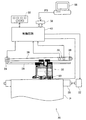
図1は、本発明の実施例としてのインクジェットプリンタ20を備えた印刷システムの概略構成図である。このプリンタ20は、キャリッジモータ24によってキャリッジ30を摺動軸34に沿って往復動させる主走査送り機構と、紙送りモータ22によって印刷用紙Pを主走査の方向と垂直な方向(「副走査方向」という。)に搬送する副走査送り機構と、キャリッジ30に搭載された印刷ヘッドユニット60を駆動してインクの吐出およびドット形成を制御するヘッド駆動機構と、これらの紙送りモータ22,キャリッジモータ24,印刷ヘッドユニット60および操作パネル32との信号のやり取りを司る制御回路40とを備えている。制御回路40は、コネクタ56を介してコンピュータ88に接続されている。
【0016】
印刷用紙Pを搬送する副走査送り機構は、紙送りモータ22の回転を用紙搬送ローラ(図示せず)に伝達するギヤトレインを備える(図示せず)。また、キャリッジ30を往復動させる主走査送り機構は、印刷用紙Pの搬送方向と垂直な方向に架設されキャリッジ30を摺動可能に保持する摺動軸34と、キャリッジ30とキャリッジモータ24との間に無端の駆動ベルト36を張設するプーリ38と、キャリッジ30の原点位置を検出する位置センサ39とを備えている。
【0017】
図2は、プリンタ20の制御回路40の構成を示すブロック図である。制御回路40は、CPU41と、プログラマブルROM(PROM)43と、RAM44と、文字のドットマトリクスを記憶したキャラクタジェネレータ(CG)45とを備えた算術論理演算回路として構成されている。この制御回路40は、さらに、外部のモータ等とのインタフェースを専用に行なうI/F専用回路50と、印刷ヘッドユニット60を駆動してインクを吐出させるヘッド駆動回路52と、紙送りモータ22およびキャリッジモータ24を駆動するモータ駆動回路54と、を備えている。
【0018】
I/F専用回路50は、パラレルインタフェース回路を内蔵しており、コネクタ56を介してコンピュータ88から供給される印刷信号PSを受け取ることができる。そして、CPU41が、I/F専用回路50を介して印刷信号PSを受け取ってRAM44内に格納する。なお、CPU41は、P−ROM43内に格納されたコンピュータプログラムを実行することによって、後述する「第1の部分ライン記録」、「全体ライン記録」、「第2の部分ライン記録」を行う。
【0019】
印刷ヘッド28は、各色毎に一列に設けられた複数のノズルnと、各ノズルnに設けられたピエゾ素子PEを動作させるアクチュエータ回路90と、を有している。アクチュエータ回路90は、ヘッド駆動回路52(図2参照)の一部であり、ヘッド駆動回路52内の図示しない駆動信号生成回路から与えられた駆動信号をオン/オフ制御する。すなわち、アクチュエータ回路90は、印刷信号PS中の画像データに基づいてCPU41が作成した印刷データに従って、各ノズルに関してオン(インクを吐出する)またはオフ(インクを吐出しない)を示すデータをラッチし、オンのノズルについてのみ、駆動信号をピエゾ素子PEに印加する。
【0020】
図3は、印刷ヘッドユニット60に設けられたノズルの配置を示す説明図である。このプリンタ20は、ブラック(K)、シアン(C)、マゼンタ(M)、イエロ(Y)の4色のインクを用いて印刷を行う印刷装置である。印刷ヘッドユニット60には、副走査方向にそれぞれ11個のノズルを備えるノズル列K、C、M、Yが主走査方向に並んで設けられている。4列の各ノズル列内のノズル間の副走査方向のピッチは、主走査ラインピッチをDとしたとき、2×Dである。これら一つ一つのノズル列が、特許請求の範囲にいう「同一色のインク滴を吐出する複数のノズル」に相当する。ここで、「主走査ライン」とは、主走査方向に並ぶ画素の列である。そして、「画素」とは、インク滴を着弾させドットを記録する位置を規定するために、印刷媒体上に仮想的に定められた方眼状の升目である。
【0021】
各ノズル列のノズルは、副走査において先に前記印刷媒体上に達するノズルから順に、前記副走査の方向にそって第1のノズル群、第2のノズル群および第3のノズル群に分類される。図3の例では、ノズル#8〜#11が第1のノズル群Iであり、ノズル#7〜#5が第2のノズル群IIであり、ノズル#1〜#4が第3のノズル群IIIである。第3ノズル群と第1ノズル群とは、副走査方向について、ノズルが設けられている範囲の幅が同じである。
【0022】
印刷ヘッドユニット60は、キャリッジモータ24によって矢印MSの方向に摺動軸34に沿って往復動される。そして、印刷用紙Pは、紙送りモータ22によって印刷ヘッド28に対して矢印SSの方向に送られる。
【0023】
A2.印刷:
(1)画像データの処理:
図4はコンピュータ88およびプリンタ20の機能ブロックを示す説明図である。図2ではハードウェア構成を説明したが、ここでは、それらの構成がどのように機能するかを、図4を使用して説明する。コンピュータ88では、所定のオペレーティングシステムの下で、アプリケーションプログラム95が動作している。オペレーティングシステムにはプリンタドライバ96が組み込まれている。アプリケーションプログラム95は、画像データの生成を行う。そして、プリンタドライバ96が画像データをプリンタ20で印刷可能な形式に変換する。
【0024】
プリンタドライバ96には、入力部100,色補正処理部101および色補正テーブルLUT、ハーフトーン処理部102、および出力部104の各機能部が用意されている。
【0025】
アプリケーションプログラム95から印刷命令が出されると、入力部100が画像データを受け取って、一旦蓄積する。色補正処理部101は画像データの色成分をプリンタ20のインクに応じた色成分に補正する色補正処理を行う。色補正処理は、画像データの色成分をプリンタ20のインクで表現可能な色成分との対応関係を予め記憶する色補正テーブルLUTを参照して行われる。ハーフトーン処理部102は、こうして色補正処理されたデータに対し、それぞれ各画素の階調値をドットの記録密度で表現するためのハーフトーン処理を行う。こうして変換処理された画像データは、出力部104により、画像データの上から順に主走査ライン1本ずつの単位で、出力信号PSとして、プリンタ20に出力される。
【0026】
プリンタドライバ96から送られた画像データは、I/F専用回路50を介して受信され、RAM44(図2参照)に格納される。このRAM44の機能を受信バッファ44aとして図4に示す。RAM44は、このほか、印刷データバッファ44b、展開バッファ44c、レジスタ44dとしても機能する。これらの機能部も図4に示す。
【0027】
CPU41(図2参照)は、受信バッファ44aに記憶された画像データを、プリンタ20で記録される順番に、すなわち、プリンタ20でのパスの順番に並べ替えて、印刷データを生成する。印刷データは、印刷の際にどのノズルが使用されるかを考慮して、生成される。また、その際、CPU41は、各パスにおけるキャリッジの移動速度や、各パスの合間に行う副走査の送り量などのデータも生成し、印刷データ内に組み込む。そして、CPU41は、印刷データを印刷データバッファ44bに格納する。このCPU41の機能を印刷データ生成部41dとして図2に示す。なお、「パス」とは、ドットの形成が行われる1回分の主走査を意味する。ここでは、「印刷データ」という用語は、狭義には、CPU41によってパスの順番に並べ替えられたデータを意味するが、広義には、その前後の様々な形態に変換および加工された段階のデータをも意味する。
【0028】
その後、図4に示すように、CPU41(図2参照)によって、印刷データバッファ44bから順次1パス分のデータが展開バッファ44cに送られる。このデータには、一度の主走査で使用される全てのノズルについての1パス分のドット形成情報が格納されている。すなわち、展開バッファ44cに送られるデータには、一度の主走査でドットが記録される複数の主走査ラインについてのデータが格納されている。そして、それらのノズルの1パス分のドット形成情報から、各ノズルがドットを形成する順に、各ノズルの1画素分のドット形成情報がまとめて取り出されて、レジスタ44dに送られる。すなわち、複数の主走査ラインについてのドット形成情報から、主走査ラインと交差する方向(副走査方向、ロウ方向)に並ぶ画素についてのドット形成情報がパラレルに切り出されて、順次、レジスタ44dに送られる。
【0029】
CPU41は、その後、切り出されたレジスタ44d内のデータを、シリアルデータに変換してヘッド駆動回路52に送る。そして、ヘッド駆動回路52がそのシリアルデータに従ってヘッドを駆動して画像を印刷する。一方、展開バッファ44c内の1パス分のデータからは、主走査の送り方を示すデータおよび副走査の送り方を示すデータも取り出され、モータ駆動回路54に送られる。図4では、モータ駆動回路54の機能部としてキャリッジモータ24を制御する主走査部54a、および紙送りモータ22を制御する副走査部54bを示している。これら主走査部54aおよび副走査部54bが、受け取ったデータに従ってヘッドの主走査および印刷用紙の搬送を行う。
【0030】
(2)同一重量のインク滴によるドットの大きさのばらつき:
図5〜図7は、それぞれ同一重量のインク滴を画素に着弾させたときのドットの広がりの違いを表す図である。図5は、隣接する周囲の画素にドットが記録されていない画素にドットd1を記録した場合のドットの大きさを示している。3個×3個の升目が画素を示し、中心の○がドットの広がりを示している。隣接する周囲の画素にドットが記録されていない画素にドットを記録した場合には、図5のように、インクは周囲の画素にも比較的広く広がる。
【0031】
図6は、副走査の方向の両側に隣接する二つの画素pU、pLを含む、複数の隣接画素にすでにドットが記録されている状態で、中心の画素にドットd3を記録した場合のドットの大きさを示している。図6においては、すでに記録されている可能性のある画素を破線で描いた丸で示している。このような場合には、既に周囲の画素に記録されたインクに遮られて、中心の画素に着弾したインクは、図5の場合に比べて広がらない。なお、破線で描かれたドットは、そのようなすべてのドットがすでに記録されていることを意味するものではない。複数の隣接画素のうちより多くの画素にドットが記録されているほど、中心の画素に記録するドットの広がりの大きさは小さくなる。
【0032】
図7は、副走査の方向の一方の側に隣接する画素pUを含む、副走査の方向の一方の側の画素にドットが記録されており、他方の側に隣接する周囲の他の画素にはドットが記録されていない画素に、ドットd2を記録した場合のドットの大きさを示している。このような場合には、ドットの広がりは図5のドットd1よりも小さく、図6のドットd3よりも大きくなる。破線で描かれたドットが、すべてすでに記録されていることを意味するものではないのは図6と同様である。そして、破線でドットが記された一方の側の画素のうち、より多くの画素にドットが記録されているほど、中心の画素に記録するドットの大きさは小さくなる。
【0033】
(3)印刷:
図8は、第1実施例において行うドットの記録のやり方を示す説明図である。ここでは説明を簡単にするために、印刷ヘッドユニット60に設けられたシアン、マゼンタ、イエロ、ブラックのノズル列うちの1列のノズルのみに着目して説明する。図8において、矢印P1,P2,P3,P4は、それぞれ1回の主走査を示している。そして、それぞれの矢印の下に示す長方形は、その主走査において記録される印刷用紙上の領域の一部(4列×21行)を切り出して示したものである。ここでは、それぞれ4列分のみの領域を示しているが、各主走査P1〜P4においては、主走査方向MSについて同様の記録が繰り返し行われる。
【0034】
たとえば、主走査P1において、一番上の主走査ラインは、ノズル#1で一つおきに画素を記録される。上から3番目の主走査ラインは、主走査P1において、ノズル#2ですべての画素にドットを記録される。ここで、「すべての画素をドットの記録対象とする」とは、必要に応じてすべての画素にドットを記録することが可能である、という意味である。よって、印刷すべき画像データによっては、すべての画素にドットが記録されないこともある。
【0035】
図9は、あるノズルを使用して、ある主走査ラインに含まれるすべての画素にドットを記録する場合のドットの記録のし方を示す図である。左右方向に並ぶ升目は、ある主走査ラインに含まれる画素を示している。矢印MSは、印刷ヘッドユニット60が送られる方向を示している。図9および後述する図10において、黒い丸は既に記録されたドットを示し、破線で描く白い丸は次に記録されるドットを示している。あるノズルを使用して、ある主走査ラインに含まれるすべての画素にドットを記録する場合には、主走査において、ノズルが各画素上を通過するにつれて、主走査ラインに含まれる各画素に、順にドットが記録されていく。よって、すでに左から4番目までの画素にドットが記録されている場合には、次には、左から5番目の画素にドットが記録される。
【0036】
図10(a)〜(c)は、第1のノズル群のノズルを使用して、ある主走査ラインに含まれる画素のうちの一部の画素にドットを記録し、第3のノズル群のノズルを使用して、第1のノズル群によってドットを記録されなかった画素にドットを記録する場合の、ドットの記録のし方の例を示す図である。第1のノズル群のノズルは、印刷ヘッドユニット60が矢印MSの方向に送られるにつれて、一つおきの画素にドットを記録していく。図10(a)に示すように、すでに左から1番目、3番目、5番目の画素にドットが記録されている場合には、次には、左から7番目の画素にドットが記録される。一方向の主走査が完了すると、図10(b)に示すように、一つおきの画素にドットが記録された状態となる。
【0037】
次に、1回以上の副走査が行われた後、図10(c)に示すように、図10(a)とは逆向きの主走査において、第3のノズル群のノズルが印刷ヘッドユニット60が矢印MSの方向に送られるにつれて、一つおきの画素にドットが記録されていく。図10(c)に示すように、すでに左から12番目、10番目の画素にドットが記録されている場合には、次には、左から8番目の画素にドットが記録される。こうして往復双方向の主走査が完了すると、その主走査ラインのすべての画素にドットが記録された状態となる。なお、CPU41は、ある主走査ラインについて、図9のような印刷が行われるか、図10のような印刷が行われるかを考慮して、印刷データの生成を行う(図4参照)。
【0038】
図8に示したドット記録方法においては、主走査P1では、ノズル#1,#3,#8,#10は、図10(a)に示したように一つおきの画素にドットを記録する。ただし、主走査ライン内の各画素に番号が振られているとすると(図10(a)〜(c)参照)、ノズル#1,#3は偶数番号が振られた画素にドットを記録し、ノズル#8,#10は、奇数番号が振られた画素にドットを記録する。ノズル#2,#4〜#7は、図9に示したように、主走査P1において、主走査ラインの各画素に順にドットを記録してゆく。
【0039】
主走査P2,P3,P4においても同様にドットの記録が行われる。ただし、図8に示すように、主走査P3は主走査P1と同じ向きに行われるが、主走査P2,P4は、主走査P1とは逆の向きに行われる。すなわち、図10においても説明したように、第1実施例においては双方向の主走査において画素にドットが記録される。各主走査の合間には、7ドットずつの副走査が行われる。なお、本明細書では、副走査の方向についての寸法は、「ドット」の単位で示す。1ドットは、副走査方向についての主走査ライン1本分の寸法である。
【0040】
上記の主走査の合間に副走査が行われると、ノズル列と印刷用紙とが相対的に移動し、記録領域が副走査方向SSについて7ドットずつ移動していく。
図8においては、各主走査において記録される領域の一部を取り出して表している。よって、各主走査の合間に行われる7ドットずつの副走査を、各主走査の記録領域を結ぶ矢印SS1で示す。なお、実際には、印刷用紙が搬送されて印刷ヘッドユニット60と印刷用紙の相対位置が変わってゆくが、図8では、説明を簡単にするために、印刷ヘッドユニット60が移動して、それにつれて記録領域が移動しているように各記録領域を表している。また、図8においては、副走査の方向を表す矢印SSについても、理解を容易にするために、実際の印刷用紙の搬送方向とは逆の向きで表している。
【0041】
第1実施例では、副走査の方向について第3のノズル群が設けられている幅は、図8から分かるように、7ドットである。主走査の合間に行う副走査SS1の送り量は、副走査の方向について第3のノズル群が設けられている幅の近傍の所定の値であることが好ましい。「第3のノズル群が設けられている幅の近傍」とは、第3のノズル群が設けられている幅の70%以上130%以下の値であることを意味する。なお、副走査の送り量は、第3のノズル群が設けられている幅の85%以上115%以下の値であることが好ましく、さらに、第3のノズル群が設けられている幅の90%以上110%以下の値であることがさらに好ましい。そのようにすれば、効率的に部分オーバーラップ印刷を行うことができる。
【0042】
図8の右端には、主走査P1〜P4でドットを記録した結果の例を示している。ここでは、4列×14行の領域を切り出して示している。各升目は画素を示している。それぞれの升目には、ドットを表す○が記されている。このドットを表す○には、大きさの異なる3種類の○がある。図5のように、隣接する周囲の画素にドットが記録されていない状態で、画素に記録されるドットは、画素を表す升目をはみ出る大きさの○で示している。そして、図6のように、副走査の方向の両側に隣接する二つの画素にすでにドットが記録されている状態で、画素に記録されるドットは、画素の升目に接しない大きさの小さな○で示している。さらに、副走査方向の両側に隣接する二つの画素にドットが記録されているわけではないが、図7のように、隣接する周囲の画素の少なくとも一つに画素が記録されている状態で、画素に記録されるドットは、画素の升目に接する大きさの○で示している。
【0043】
また、各画素内の三角は、主走査の方向を示している。黒い右向きの三角が記されている画素は、右向きの主走査でドットを記録される。白い左向きの三角が記されている画素は、左向きの主走査でドットを記録される。
【0044】
上述のようにしてドットを記録すると、各画素にドットを記録するノズルと、各画素へのドットの記録順序の組み合わせは、副走査の方向について所定の幅で繰り返される。この繰り返しの単位の幅は、7ドットである。図8の例では、範囲B1に示した記録と、範囲B2に示した記録が交互に繰り返される。すなわち、ある領域を一色で印刷した場合には、範囲B1のテクスチャと範囲B2のテクスチャが繰り返されることになる。
【0045】
なお、範囲B1、B2の各画素には、すべてドットを示す○が記されている。しかし、現実には、各画素にすべてドットが記録されることはまれである。ここでは、説明を単純にするために、すべての画素にドットを記録するかのような前提で説明を行い、すべての画素に○を付してしている。これらの画素に付された○は、画像データに応じてドットを記録することが可能であることを意味するものであり、ドットが記録される場合には、記録されるドットの大きさが画素によって違ってくることを説明するためのものである。これらの○は、実際にドットが記録されることを意味するものではない。
【0046】
図8の例においては、主走査P1およびP2を行っている時点は、印刷開始直後の時点であり、主走査P3以降が定常状態であるので、主走査P3を例に各ノズル群のドットの記録について説明する。主走査P3において、第1のノズル群のノズルであるノズル#8とノズル#10は、それらのノズルと向かい合う位置にある主走査ラインに含まれる画素のうちの一部の画素にドットを記録している。このようなドットの記録が、特許請求の範囲にいう「第1の部分ライン記録」に相当する。
【0047】
また、第2のノズル群のノズルであるノズル#4〜#7は、主走査P3において、それらのノズルと向かい合う位置にある主走査ラインに含まれるすべての画素にドットを記録している。このようなドットの記録が、特許請求の範囲にいう「全体ライン記録」に相当する。
【0048】
そして、第3のノズル群のノズルであるノズル#1〜#4は、主走査P3において、それらのノズルと向かい合う位置にある主走査ラインに含まれる画素であって、第1のノズル群によってドットを記録されていない画素にドットを記録している。たとえば、ノズル#2とノズル#4とは、第1のノズル群のノズルによってドットを記録されていない主走査ラインにドットを記録している。一方、ノズル#1とノズル#3とは、主走査P1で第1のノズル群のノズル#8と#10によってドットを記録されている主走査ラインに、ドットを記録している。しかし、主走査P1で第1のノズル群のノズル#8と#10によってドットを記録されているのは、奇数番目の画素であるのに対して、ノズル#1とノズル#3とがドットを記録しているのは、偶数番目の画素である。よって、第3のノズル群のノズルであるノズル#1〜#4は、それまでに行われた主走査で第1のノズル群によってドットを記録されていない画素にドットを記録していることになる。このようなドットの記録が、特許請求の範囲にいう「第2の部分ライン記録」に相当する。
【0049】
なお、第3のノズル群のノズル#2,#4は、それぞれのノズルと向かい合う位置にある主走査ラインに含まれるすべての画素にドットを記録している。しかし、同じく第3のノズル群のノズル#1,#3は、それらのノズルと向かい合う位置にある主走査ラインに含まれるすべての画素にドットを記録していない。このような場合にも、第3のノズル群全体としては、ノズル群のすべてのノズルと向かい合う位置にある主走査ラインのすべての画素に、ドットを記録してはいない。よって、そのような場合も「ノズル群のノズルと向かい合う位置にある主走査ラインに含まれる画素のうちの一部の画素をドットの記録対象とする」に該当するものとする。本実施例では、第1のノズル群の一部のノズルが向かい合う位置にある主走査ラインのすべての画素にドットを記録してはいない。しかし、本発明の態様において、第1のノズル群の一部のノズルが向かい合う位置にある主走査ラインのすべての画素にドットを記録する場合にも、他の一部のノズルが向かい合う位置にある主走査ラインのすべての画素にドットを記録していない場合には、「ノズル群のノズルと向かい合う位置にある主走査ラインに含まれる画素のうちの一部の画素をドットの記録対象とする」に該当する。
【0050】
P−ROM43に格納されたプログラムを実行されることで、CPU41がこれらの第1の部分ライン記録、全体ライン記録、第2の部分ライン記録を実行する。CPU41の機能部としての第1の部分ライン記録部41a、全体ライン記録部41b、第2の部分ライン記録部41cを図2に示す。
【0051】
以下では、特定の主走査のみにあてはまる話ではなく、各主走査にあてはまる話について説明するので、図8に示す主走査P1を例に説明する。図8では、主走査P1において第1のノズル群によって記録される領域をIで示し、第2のノズル群によって記録される領域をIIで示し、第3のノズル群によって記録される領域をIIIで示している。図8において主走査P1で記録される領域の一部として示した長方形の領域内で、第1のノズル群のノズル#8,#10で記録される画素は4個である。一つの主走査ラインに含まれる端から端までの画素の数をAP(APは正の整数)とする。図8で各主走査について示している領域は4列の領域であるので、主走査P1で第1のノズル群のノズルによって記録される画素の数N1は、(4×AP/4)個、すなわち、AP個である。
【0052】
同様に、主走査P1で記録される領域の一部として示した長方形の領域内で、第3のノズル群のノズル#1〜#4で記録される画素は12個である。よって、主走査P1で第3のノズル群のノズルによって記録される画素の数N3は、(12×AP/4)個、すなわち、(AP×3)個である。他の主走査においても、第1のノズル群のノズルによって記録される画素の数N1と、第3のノズル群のノズルによって記録される画素の数N3とは、それぞれ上記と同じである。すなわち、主走査において第1のノズル群のノズルによって記録される画素の数N1と、第3のノズル群のノズルによって記録される画素の数N3の比は、1:3である。
【0053】
なお、第1のノズル群と第3のノズル群の副走査方向の幅は以下のように規定される。第1のノズル群と第3のノズル群の幅を規定する際には、第1のノズル群と第3のノズル群のうち、一度の主走査においてドットを記録する画素が少ない方のノズル群を基準とする。以下、その基準となるノズル群を「基準ノズル群」と呼ぶ。基準ノズル群の副走査方向の一方の端を規定する第1の基準ノズルは、全ノズルのうち、副走査方向の端に位置するノズルである。基準ノズル群が第1のノズル群であれば、第1の基準ノズルは、副走査において最初に印刷媒体上に到達するノズルである。基準ノズル群が第3のノズル群であれば、第1の基準ノズルは副走査において最後に印刷媒体上に到達するノズルである。
【0054】
第1の基準ノズルを基点として、第1〜第3のノズル群の副走査方向についての中心に向かって各ノズルを順に検討したときに、最初に現れる、以下のような条件を満たすノズルが、第2のノズル群の端のノズルである。そして、その一つ手前のノズルが、基準ノズル群の他方の端を規定する第2の基準ノズルである。その条件とは、「主走査において、向かい合う位置にある主走査ラインに含まれるすべての画素をドットの記録対象とする」ノズルという条件である。このようにして基準ノズル群の第1の基準ノズルと第2の基準ノズルとが定められる。
【0055】
第1の基準ノズルから第2の基準ノズルまでの副走査方向についての範囲が、基準ノズル群が設けられている副走査方向の範囲である。そして、第1の基準ノズルから第2の基準ノズルまでの副走査方向についての距離が、基準ノズル群が設けられている副走査方向の幅である。第1のノズル群と第3のノズル群のうち、基準ノズル群ではない方のノズル群の幅は、基準ノズル群の幅と等しい値とされる。
【0056】
(4)印刷方法の決定:
上記の第1のノズル群のノズルによって記録される画素の数N1と、第3のノズル群のノズルによって記録される画素の数N3との比は、印刷結果の品質が高くなるように設定される。以下では、第1のノズル群のノズルによって記録される画素の数N1と、第3のノズル群のノズルによって記録される画素の数N3との比をどのようにして決定するかを説明する。
【0057】
なお、N1とN3の比を決定する際には、実際に、N1とN3の値を様々に変えて複数回、印刷を行ってみて、最も印刷結果の品質が高かった設定値を選択することとしてもよい。そのような態様とすれば、実際に印刷結果の品質が高くなるような印刷方法を選択することができる。特に、印刷すべき多くの画像について、ある系統の色が多く使われるなど、印刷する画像に一定の傾向がある場合には、実際の印刷結果に基づいてN1,N3を定めれば、そのような画像の印刷に適した設定値を選択することもできる。
【0058】
図11は、隣接する周囲の画素にドットが記録されていない画素にドットを記録した場合のドットd1sを示している。図12は、副走査の方向の両側に隣接する二つの画素pU、pLにドットdU、dLが記録されている状態で、間の画素にドットを記録した場合のドットd3sを示している。そして、図13は、副走査の方向の一方の側に隣接する画素pUにドットdUが記録されており、他方の側に隣接する周囲の他の画素にはドットが記録されていない状態で中央の画素に、ドットd2sを記録した場合のドットを示している。ドットd1s〜d3s、dU、dLを形成するために吐出されたインク滴の重量は同じである。
【0059】
第1のノズル群のノズルによって記録される画素の数N1と、第3のノズル群のノズルによって記録される画素の数N3とを決める際には、図11〜図13のように、それぞれ印刷用紙上にドットd1s〜d3sを形成する。そして、形成したドットをそれぞれCCDカメラで撮影し、ドットd1s、d2s、d3sの面積W1,W2,W3を求める。本実施例においては、たとえば、ドットd2sの面積W2を100としたとき、ドットd1sの面積W1が160であり、ドットd3sの面積W3が80であったとする。
【0060】
なお、図12に示すドットd3sの面積W3を求める際には以下のようにする。すなわち、あらかじめ印刷用紙上にドットdU、dLを記録して、CCDでこれらを撮影し、ドットdU、dLの面積を求めておく。その後、ドットd3sを記録して、あらためてドットdU,dL,d3sをCCDカメラで撮影し、ドットdU,dL,d3sの合計の面積を求める。そして、ドットdU,dL,d3sの合計の面積の値から、先に求めたドットdU、dLの面積を引くことで、ドットd3sの面積W3を求めることができる。図13に示すドットd2sについても同様である。
【0061】
なお、図11のドットd1sは、図5のドットd1ような、隣接する周囲の画素にドットが記録されていない状態で、画素に記録されるドットを代表するドットである。また、図12のドットd3sは、図6のドットd3ような、隣接する周囲の画素にドットがすでに記録されている状態で、画素に記録されるドットを代表するドットである。図6のドットd3の場合は、周囲に破線の○で示したドットは可能性として存在するものであり、実際には記録されていることもあるし記録されていないこともある。これに対して、図12のドットd3sを記録する場合には、それら可能性として存在するドットのうち、ドットdU,dLを記録した状態で、ドットd3sを記録する。そして、図6のドットd3の標準的な面積としてドットd3sの面積W3を求める。図7のドットd2と図13のドットd2sの関係も同様である。
【0062】
第1のノズル群のノズルによって記録される画素の数N1と、第3のノズル群のノズルによって記録される画素の数N3とは、上記のようにして求めたドットd1s,d2s,d3sの面積W1,W2,W3に基づいて定めることができる。すなわち、N1,N3は、下記の式(2)から求められるW13がW2の近傍の値となるように、定められる。
【0063】
W13={W1×N1/(N1+N3)}+{W3×N3/(N1+N3)}・・・(2)
【0064】
ここで、「W13がW2の近傍の値」であるとは、W13がW2の70%以上130%以下の値であることを意味する。なお、W13がW2の85%以上115%以下の値となるようにN1,N3を定めることがより好ましく、W13がW2の90%以上110%以下の値となるようにN1,N3を定めることがさらに好ましい。
【0065】
上述のように、W1は160、W3は80であったので、式(2)は次のようになる。
【0066】
W13=(160×N1+80×N3)/(N1+N3) ・・・(3)
【0067】
このW13がW2、すなわち100に等しくなるためには、N1とN3が以下の関係を満たせばよい。
【0068】
N1:N3=1:3 ・・・(4)
【0069】
図8に示した印刷方法における、第1のノズル群のノズルによって記録される画素の数N1と、第3のノズル群のノズルによって記録される画素の数N3の比は、このようにして定められる。
【0070】
第1のノズル群は、第1〜第3のノズル群の中で最初に印刷媒体上の各主走査ラインに達する。さらに、ノズルピッチは2ドットであり、隣り合う主走査ラインには同時にはドットは記録されない。このため、第1のノズル群のノズルが吐出するインク滴は、隣接する周囲の画素にドットが記録されていない画素に着弾する可能性が高い。よって、第1のノズル群のノズルが形成するドットは、図11に示すドットd1sの大きさとなる可能性が高い。
【0071】
また、第3のノズル群は、第1〜第3のノズル群の中で最後に印刷媒体上の各主走査ラインに達する。このため、第3のノズル群のノズルが吐出するインク滴は、副走査の方向の両側に隣接する二つの画素にドットが記録されている画素に着弾する可能性が高い。よって、第3のノズル群のノズルが形成するドットは、図12に示すドットd3sに近い大きさとなる可能性が高い。
【0072】
さらに、第2のノズル群は、第1のノズル群よりも後で第3のノズル群よりも先に印刷媒体上の各主走査ラインに達する。このため、第2のノズル群のノズルが吐出するインク滴は、副走査の方向の一方の側に隣接する画素にドットが記録されており、他方の側に隣接する画素にはドットが記録されていない画素に、着弾する可能性が高い。よって、第2のノズル群のノズルが形成するドットは、図13に示すドットd2sに近い大きさとなる可能性が高い。
【0073】
本実施例では、第1のノズル群のノズルと第3のノズル群のノズルとによって記録される主走査ライン群の画素中の、第1のノズル群によるドットと、第3のノズル群によるドットとの存在比を、式(2)に基づいて定めている。式(2)で得られるW13は、第1のノズル群のノズルと第3のノズル群のノズルとによって記録される主走査ライン群の画素中のドットの期待値である。本実施例では、第1のノズル群のノズルと第3のノズル群のノズルとによって記録される主走査ライン群の画素中のドットの期待値が、W2の近傍の値となるように、第1のノズル群によるドットと、第3のノズル群によるドットとの比(存在比)を定めている。よって、第1のノズル群のノズルと第3のノズル群のノズルとによって記録される領域と、第2のノズル群のノズルのみによって記録される領域と、の違いが目立ちにくい。このため、範囲B1のテクスチャと範囲B2のテクスチャ(図8参照)の違いが目立たなくなる。その結果、印刷結果の品質が高い。なお、このような効果は、N1とN3の数自体をそれぞれ適宜の値に定めることでも得えられ、また、N1とN3の比を適宜の値に定めることでも得られる。
【0074】
なお、図3に示すように、本実施例では、各色のノズル列は主走査方向MSに並ぶように配されている。このため、一つの画素に2色以上のインク滴を重ねて打つ場合には、主走査の向きによってインクの重ね順が変わってくる。たとえば、シアン(C)のインク滴とイエロ(Y)のインク滴を一つの画素に重ねて打つ場合、主走査の往路で記録するか、復路で記録するかで、シアンのインク滴が先に印刷用紙に着弾するか、イエロのインク滴が先に印刷用紙に着弾するかが変わってくる。その結果、それぞれ同じ量のインク滴を吐出しても、色目がわずかに変わってくる。
【0075】
本実施例では、これら双方向印刷におけるインクの重ね順起因する色目の変化の問題をなくすものではない。しかし、着弾させるインク滴の種類、重量および重ね順が同じ画素同士においても、最初に着弾するインクの広がりの違いに起因する画質の劣化の問題が存在する。そして、本実施例のような印刷を行えば、そのようなインクの広がりの違いに起因する印刷結果の品質の劣化を低減することができる。よって、本実施例のような印刷を行えば、複数色のインクを重ねて記録する必要がある色についても、印刷結果の品質を向上させることができる。
【0076】
図14は、比較例において行うドットの記録のやり方を示す説明図である。比較例のドット記録方法においては、各主走査では、ノズル#1,#3,#9,#11が、それぞれ向かい合う主走査ライン中の偶数番号が振られた画素にドットを記録する。そして、ノズル#2,#4,#8,#10が、それぞれ向かい合う主走査ライン中の奇数番号が振られた画素にドットを記録する。ノズル#5〜#7は、主走査において、主走査ラインの各画素に順にドットを記録してゆく。
【0077】
図14において主走査P1で記録される領域の一部として示した長方形の領域内で、第1のノズル群のノズル#8〜#11で記録される画素は8個である。よって、一つの主走査で第1のノズル群のノズルによって記録されるノズルの数N1’は、(8×AP/4)個、すなわち、(AP×2)個である。
【0078】
同様に、主走査P1で記録される領域の一部として示した長方形の領域内で、第3のノズル群のノズル#1〜#4で記録される画素も8個である。よって、一つの主走査で第3のノズル群のノズルによって記録されるノズルの数N3’も(AP×2)個である。すなわち、第1のノズル群のノズルによって記録される画素の数N1’と、第3のノズル群のノズルによって記録される画素の数N3’との比は1:1である。
【0079】
このような態様においては、第1のノズル群のノズルと第3のノズル群のノズルとによって記録される主走査ライン群の画素中のドットの期待値W13’は、式(2)から、120となる。すなわち、図8の例の期待値W13の値100に比べてW2との差が大きい。よって、図8の場合に比べて第1のノズル群のノズルと第3のノズル群のノズルとによって記録される領域と、第2のノズル群のノズルのみによって記録される領域と、の違いが目立つ。よって、図8の場合に比べて範囲B1’のテクスチャと範囲B2’のテクスチャ(図14参照)の違いが目立ち、印刷結果の品質が図8の場合に比べて低くなる。
【0080】
B.第2実施例:
第1実施例では、第2のノズル群のノズルは、一度の主走査で向かい合う位置にある主走査ラインのすべての画素にドットを記録していた。しかし、第2実施例では、第2のノズル群のノズルも複数回の主走査で、向かい合う位置にある主走査ラインの全画素にドットを記録する。第2実施例の印刷装置のハードウェア構成は、第1実施例の印刷装置と同じである。
【0081】
図15は、第2実施例において行うドットの記録のやり方を示す説明図である。図の左側には主走査ラインの番号を付している。図15では、第13ラインから第36ラインまでを示している。また、各主走査P1〜P8に対応させて示した4列の画素は、それぞれ左から順に、4で割ったときに1余る番号の画素、4で割ったときに2余る番号の画素、4で割ったときに3余る番号の画素、4で割りきれる番号の画素であるものとする(図9および図10参照)。図15に示すように、第2実施例においては、往路と復路の2回の主走査を行うごとに、送り量7ドットの副走査SS2を1回行う。すなわち、副走査方向について同じ位置で、往復2回の主走査が行われる。
【0082】
第2のノズル群のノズル#5〜#7は、主走査の往路で、図10(a)に示した例と同じように奇数番号の画素にドットを記録する。そして、主走査の復路で図10(c)に示した例と同じように偶数番号の画素にドットを記録する。その結果、往復2回の主走査で、ノズルと向かい合う位置にある主走査ラインのすべての画素にドットが記録される。例えば、図15においては、第16、18,20ラインは、主走査P3,P4において、上記のような記録方法で記録される。
【0083】
第1のノズル群のノズル#9とノズル#11は、主走査の往路において、4で割ったときに1余る番号の画素にドットを記録する。そして、主走査の復路においては、ドットを記録しない。その結果、往復2回の主走査で、向かい合う位置にある主走査ラインの画素のうち、4で割ったときに1余る番号の画素にのみドットが記録される。例えば、図15においては、第17,21ラインは、主走査P1,P2において、上記のような記録方法で記録される。
【0084】
第1のノズル群のノズル#8とノズル#10は、主走査の往路においてはドットを記録しない。そして、主走査の復路において、4で割ったときに3余る番号の画素にドットを記録する。その結果、往復2回の主走査で、向かい合う位置にある主走査ラインの画素のうち、4で割ったときに3余る番号の画素にのみドットが記録される。例えば、図15においては、第15,19ラインは、主走査P1,P2において、上記のような記録方法で記録される。
【0085】
第3のノズル群のノズル#1とノズル#3は、主走査の往路において、4で割ったときに2余る番号の画素にドットを記録する。そして、主走査の復路において、4で割ったときに1余る番号の画素と、4で割りきれる番号の画素とにドットを記録する。その結果、往復2回の主走査で、向かい合う位置にある主走査ラインの画素のうち、4で割ったときに1余る番号の画素と、4で割ったときに2余る番号の画素と、4で割りきれる番号の画素と、にドットが記録される。例えば、図15においては、第15,19ラインは、主走査P5,P6において、上記のような記録方法で記録される。
【0086】
第3のノズル群のノズル#1がドットを記録する画素は、それまでの主走査で第1のノズル群のノズル#8がドットを記録しなかった画素である。たとえば、第15ラインは、主走査P2においてノズル#8によって、4で割ったときに3余る番号の画素にドットを記録される。そして、その後、主走査P5,P6においてノズル#1によって残りの画素にドットを記録される。その結果、全ての画素にドットを記録される。第3のノズル群のノズル#3と、第1のノズル群のノズル#10の関係も同様である。
【0087】
第3のノズル群のノズル#2とノズル#4は、主走査の往路において、4で割ったときに2余る番号の画素と、4で割ったときに3余る番号の画素とにドットを記録する。そして、主走査の復路において、4で割りきれる番号の画素にドットを記録する。例えば、図15においては、第17,21ラインは、主走査P5,P6において、上記のような記録方法で記録される。
【0088】
第3のノズル群のノズル#2がドットを記録する画素は、それまでの主走査で第1のノズル群のノズル#9がドットを記録しなかった画素である。たとえば、第17ラインは、主走査P1においてノズル#9によって、4で割ったときに1余る番号の画素にドットを記録され、その後、主走査P5,P6においてノズル#2によって残りの画素にドットを記録される。その結果、全ての画素にドットを記録される。第3のノズル群のノズル#4と、第1のノズル群のノズル#11の関係も同様である。
【0089】
図16(a)〜(d)は、第1のノズル群のノズル#9を使用して、図15の第17ラインに含まれる画素のうちの一部の画素にドットを記録し、第3のノズル群のノズル#2を使用して、第1のノズル群によってドットを記録されなかった画素にドットを記録する場合の、ドットの記録のし方の例を示す図である。各図においては、各主走査の向きを矢印で示している。そして、その主走査よりも前にすでに記録されているドットは白い丸で示し、その主走査で記録するドットは黒い丸で示している。
【0090】
図15の第17ラインを例に挙げて、1本の主走査ラインへのドットの記録のされ方を時間経過に沿って説明する。第17ラインは、まず、主走査P1において、ノズル#9によって、図16(a)に示すように4で割ったときに1余る番号の画素にドットを記録される。そして、主走査P2においては、図16(b)に示すようにドットを記録されない。その後、第17ラインは、主走査P5において、ノズル#2によって、図16(c)に示すように、4で割ったときに2余る番号の画素と、4で割ったときに3余る番号の画素と、にドットを記録される。そして、主走査P6において、同じくノズル#2によって、図16(d)に示すように4で割りきれる番号の画素にドットを記録される。第17ラインはこのようにして全画素にドットを記録される。
【0091】
第1のノズル群のノズルによって記録される画素の数N1と、第3のノズル群のノズルによって記録される画素の数N3とが決定された場合、その条件を満たすような印刷は、第2実施例のような態様として実現することもできる。
【0092】
C.変形例:
なお、この発明は上記の実施例や実施形態に限られるものではなく、その要旨を逸脱しない範囲において種々の態様において実施することが可能であり、例えば次のような変形も可能である。
【0093】
第1実施例においては、ドットd2s(図13参照)の面積W2が100であるのに対して、ドットd1s(図11参照)の面積W1は160、ドットd3s(図12参照)の面積W3が80であった。その結果、第1のノズル群のノズルによって記録される画素の数N1と、第3のノズル群のノズルによって記録される画素の数N3との比は、1:3であった。しかし、N1とN3の比は、任意の値を取ることができる。たとえば、ドットd2sの面積W2が100であるのに対して、ドットd1sの面積W1が300、ドットd3sの面積W3が50である場合には、N1:N3は1:4になる。すなわち、N1とN3とが異なる値であればよく、N1とN3は、印刷結果の品質が高くなるような適宜の値とすることができる。ただし、インク滴の広がりの傾向から(図11〜図13参照)、N3はN1の2.5倍以上であることが好ましく、N1の3倍以上であることがより好ましい。そして、N3はN1の4倍以上であることがより好ましい。
【0094】
上記実施例においては、図8に示すように、第1のノズル群のノズルによって記録される画素の数N1は、第3のノズル群のノズルによって記録される画素の数N3よりも少なかった。これは、図11のドットd1sの面積W1が180であり、図12のドットd3sの面積W3が80であったためである。すなわち、ドットd3sの面積W3の方が、ドットd1sの面積W1よりも、図13のドットd2sの面積W2に近かったためである。
【0095】
ドットd3sの面積W3と、ドットd1sの面積W1とが、それぞれ均等にW2に近ければ、式(2)の条件を満たすように定められたN1とN3の比は、1:1となる。一方、ドットd1sの面積W1の方が、ドットd3sの面積W3よりも、図13のドットd2sの面積W2に近ければ、式(2)に従って定めたN1とN3の関係は、N1>N3となる。よって、本発明においては、N1>N3となることもある。すなわち、第1のノズル群のノズルによって記録される画素の数N1と、第3のノズル群のノズルによって記録される画素の数N3とは、印刷結果の品質が高くなるように適宜の値に定めることができる。
【0096】
なお、第1のノズル群のノズルによって記録される画素の数N1と、第3のノズル群のノズルによって記録される画素の数N3を、様々に変えて印刷を行い、その中から最も印刷結果の品質が高かったN1、N3の組み合わせ(または比)を採用する場合には、式(1)に基づいて、逆に、W1とW3の比を求めることができる。以下に、式(1)において、W1をW1cとし、W3をW3cとし、左辺にW2cを代入したものを示す。
【0097】
W2c={W1c×N1/(N1+N3)}+{W3c×N3/(N1+N3)} ・・・(5)
【0098】
上記のようにして実際の印刷結果に基づいて得られたN1,N3にから計算した{N1/(N1+N3)}をr1とし、{N3/(N1+N3)}をr3とすると、式(5)は、以下のようになる。
【0099】
1={(W1c/W2c)×r1}+{(W3c/W2c)×r3} ・・・(6)
【0100】
r1とr3は、実際に印刷結果の品質が高くなるN1,N3の組み合わせから計算できるので、上記式(6)によれば、(W1c/W2c)と(W1c/W2c)の比が得られる。たとえば、W2cを100としたときの、W1cおよびW3cを、上記式(6)に基づいて得ることができる。
【0101】
第1実施例においては、ドットd1s,d2s,d3sを実際に記録して、それらドットに基づいてN1,N3を定めた。そのような場合においては、式(1)W1,W2,W3は、面積であった。しかし、第1のノズル群のノズルによって記録される画素の数N1と、第3のノズル群のノズルによって記録される画素の数N3を、様々に変えて実際に印刷を行い、その中から最も印刷結果の品質が高かったN1、N3の組み合わせ(または比)を採用する場合においては、式(6)中のW1c、W2c、W3cは、全体的なカラーのバランスにおける特定1ドットの寄与率としての意味を持つ。言いかえれば、W1c、W2c、W3cは、図5〜図7のようにして記録されたドットd1,d2,d3がそれぞれどれほど目立つのかの指標であり、それぞれどれほどその色の発色に貢献するのかを表す指標である。W1cがドットd1の寄与率であり、W2cがドットd2の寄与率であり、W3cがドットd3の寄与率である。
【0102】
この寄与率は、各ドットの実際の面積が大きくなるほど大きくなると考えられるが、両者は必ずしも比例関係にあるわけではない。そして、このようにして求められる寄与率は、インクの重なり順・用紙メディアへの印刷順による浸透量の差等が要因となって印刷順に従って変化する。様々な印刷パラメータを設定する際に、上記のようにして求めた寄与率を考慮して印刷パラメータを設定すれば、印刷結果の品質が高くなるパラメータ設定を行うことができる。
【0103】
上記実施例においては、ノズルピッチは、2ドットであった。しかし、ノズルピッチは、6ドット,8ドットなど、主走査ラインのピッチのk倍(kは2以上の整数)とすることができる。そして、主走査ライン中の各画素へのドットの記録は、一方向の主走査において行われてもよいし、双方向の主走査において行われてもよい。
【0104】
また、第1実施例では、第2のノズル群によってドットを記録される主走査ラインは、1度の主走査ですべての画素にドットを記録されていた。そして、第1および第3のノズル群によってドットを記録される主走査ラインは、2度の主走査ですべての画素にドットを記録されていた。また、第2実施例では、第2のノズル群によってドットを記録される主走査ラインも、第1および第3のノズル群によってドットを記録される主走査ラインも、2度の主走査ですべての画素にドットを記録されていた。しかし、各主走査ラインの全ての画素にドットを記録するのに必要な主走査回数はこれに限られるものではない。すなわち、第2のノズル群によってドットを記録される主走査ライン、第1および第3のノズル群によってドットを記録される主走査ライン、いずれも、3回以上の主走査で全画素にドットを記録される態様とすることができる。ただし、第2のノズル群によってドットを記録される主走査ラインよりも、第1および第3のノズル群によってドットを記録される主走査ラインの方が、全画素にドットを記録されるのに要する主走査回数が多い態様とすれば、印刷結果の品質が高くなる。
【0105】
また、上記実施例では、オーバーラップ印刷が行われる主走査ラインについて、2回の主走査でその主走査ラインのすべての画素にドットが記録された。しかし、そのような態様だけでなく、3回以上の主走査で全画素を記録する態様とすることもできる。すなわち、印刷の際には、複数回の主走査でその主走査ラインのすべての画素にドットを記録することとし、主走査ライン上を通過する各ノズルが、主走査ラインに含まれる互いに異なる画素にドットを記録するような態様とすればよい。そのような態様とすれば、一つのノズルの特徴が主走査ラインに大きく反映されるのを防ぐことができる。
【0106】
上記実施例においては、各色のインクを吐出するノズルは、一列に配されていたが、各ノズル群に含まれるノズルは、2列に配されていてもよく、さらに、3列以上であってもよい。また、ノズル群のノズルは、副走査方向について互い違いに配される、いわゆる「千鳥」配列に配されていてもよい。そして、上記実施例においては、各印刷ヘッド内において、シアン、マゼンタ、イエロ、ブラックの各ノズル列が、主走査方向に並んでいたが、各色のインクを吐出するノズル群は、副走査方向SSについて異なった位置に設けられていてもよい。すなわち、それぞれ同一色のインク滴を吐出する複数のノズルが、副走査の方向について、主走査ラインのピッチのk倍(kは2以上の整数)のノズルピッチで配されていればよい。
【0107】
上述した様々な態様においても、副走査によって比較的後に印刷媒体上に達するノズル群(第3のノズル群)は、隣接する周囲の画素にドットがすでに記録されている画素にドットを記録することになる可能性が高い。そして、副走査によって比較的先に印刷媒体上に達するノズル群(第1のノズル群)は、隣接する周囲の画素にドットが記録されていない画素にドットを記録することになる可能性が高い。このため、比較的後で印刷媒体上に達するノズル群が吐出するインク滴によって形成されるドットは、比較的小さくなる可能性が高く、比較的先に印刷媒体上に達するノズル群が吐出するインク滴によって形成されるドットは、比較的大きくなる可能性が高い。そして、それらのノズル群の間の位置に設けられているノズル群(第2のノズル群)によって記録されるドットは、それらのノズル群によるドットの大きさの間の大きさとなる可能性が高い。
【0108】
よって、比較的先に印刷媒体上に達するノズル群がドットを記録する画素の数と、比較的後で印刷媒体上に達するノズル群がドットを記録する画素の数とを、適宜の値に設定することで、以下のような効果が得られる。すなわち、比較的先に印刷媒体上に達するノズル群と比較的後で印刷媒体上に達するノズル群とによってドットを記録される領域のドットの期待値を、それらのノズル群の間の位置に設けられているノズル群(第2のノズル群)のみによって記録される領域のドットの大きさに近づけることができる。よって、印刷結果の品質を高くすることができる。
【0109】
上記各実施例では、インクジェットプリンタについて説明したが、本発明はインクジェットプリンタに限らず、一般に、印刷ヘッドを用いて印刷を行う種々の印刷装置に適用可能である。また、本発明は、インク滴を吐出する方法や装置に限らず、他の手段でドットを記録する方法や装置にも適用可能である。
【0110】
上記各実施例において、ハードウェアによって実現されていた構成の一部をソフトウェアに置き換えるようにしてもよく、逆に、ソフトウェアによって実現されていた構成の一部をハードウェアに置き換えるようにしてもよい。例えば、図2に示したCPU41の一部の機能を専用回路などのハードウェアによって実現することもでき、ヘッド駆動回路52の一部の機能をソフトウェアによって実現することも可能である。
【図面の簡単な説明】
【図1】本発明の実施例としてのインクジェットプリンタ20を備えた印刷システムの概略構成図。
【図2】プリンタ20の制御回路40の構成を示すブロック図。
【図3】印刷ヘッドユニット60に設けられたノズルの配置を示す説明図。
【図4】コンピュータ88およびプリンタ20の機能ブロックを示す説明図。
【図5】隣接する周囲の画素にドットが記録されていない画素にドットd1を記録した場合のドットの大きさを示す説明図。
【図6】副走査の方向の両側に隣接する二つの画素pU、pLを含む、複数の隣接画素にすでにドットが記録されている状態で、中心の画素にドットd3を記録した場合のドットの大きさを示す説明図。
【図7】副走査の方向の一方の側に隣接する画素pUを含む、副走査の方向の一方の側の画素にドットが記録されており、他方の側に隣接する周囲の他の画素にはドットが記録されていない画素に、ドットd2を記録した場合のドットの大きさを示す説明図。
【図8】第1実施例において行うドットの記録のやり方を示す説明図。
【図9】あるノズルを使用して、ある主走査ラインに含まれるすべての画素にドットを記録する場合のドットの記録のし方を示す説明図。
【図10】第1のノズル群のノズルを使用して、ある主走査ラインに含まれる画素のうちの一部の画素にドットを記録し、第3のノズル群のノズルを使用して、第1のノズル群によってドットを記録されなかった画素にドットを記録する場合の、ドットの記録のし方の例を示す説明図。
【図11】隣接する周囲の画素にドットが記録されていない画素にドットを記録した場合のドットd1sを示す説明図。
【図12】副走査の方向の両側に隣接する二つの画素pU、pLにドットdU、dLが記録されている場合に、間の画素にドットを記録した場合のドットd3sを示す説明図。
【図13】副走査の方向の一方の側に隣接する画素pUにドットdUが記録されており、他方の側に隣接する周囲の他の画素にはドットが記録されていない画素に、ドットd2sを記録した場合のドットを示す説明図。
【図14】比較例において行うドットの記録のやり方を示す説明図。
【図15】第2実施例において行うドットの記録のやり方を示す説明図。
【図16】第1のノズル群のノズルを使用して、第17ラインに含まれる画素のうちの一部の画素にドットを記録し、第3のノズル群のノズルを使用して、第1のノズル群によってドットを記録されなかった画素にドットを記録する場合の、ドットの記録のし方の例を示す説明図。
【符号の説明】
20…インクジェットプリンタ
22…紙送りモータ
24…キャリッジモータ
28…印刷ヘッド
30…キャリッジ
32…操作パネル
34…摺動軸
36…駆動ベルト
38…プーリ
39…位置センサ
40…制御回路
41…CPU
41a…第1の部分ライン記録部
41b…全体ライン記録部
41c…第2の部分ライン記録部
41d…印刷データ生成部
43…ROM
44…RAM
44a…受信バッファ
44b…印刷データバッファ
44c…展開バッファ
44d…レジスタ
50…I/F専用回路
52…ヘッド駆動回路
54…モータ駆動回路
54a…主走査部
54b…副走査部
56…コネクタ
60…印刷ヘッドユニット
88…コンピュータ
90…アクチュエータ回路
95…アプリケーションプログラム
96…プリンタドライバ
100…入力部
101…色補正処理部
102…ハーフトーン処理部
104…出力部
B1…一つのテクスチャの範囲
B2…他の一つのテクスチャの範囲
K…ブラックノズル列
LUT…色補正テーブル
MS…主走査方向を示す矢印
N1…第1のノズル群のノズルによって記録される画素の数
N3…第3のノズル群のノズルによって記録される画素の数
P…印刷用紙
P1〜P4…主走査
PE…ピエゾ素子
PS…印刷信号(出力信号)
SS…副走査方向を示す矢印
SS1,SS2…副走査
W1…ドットd1sの面積
W2…ドットd2sの面積
W3…ドットd3sの面積
d1…隣接する周囲の画素にドットが記録されていない画素に、記録されるドット
d1s…隣接する周囲の画素にドットが記録されていない画素にドットを記録した場合のドット
d2…副走査の方向の一方の側の画素にドットが記録されており、他方の側に隣接する周囲の他の画素にはドットが記録されていない画素に、記録されるドット
d2s…副走査の方向の一方の側に隣接する画素pUにドットdUが記録されており、他方の側に隣接する周囲の他の画素にはドットが記録されていない画素に、ドットを記録したときのドット
d3…副走査の方向の両側に隣接する二つの画素を含む、複数の隣接画素にすでにドットが記録されている状態で、中心の画素にドットd3を記録した場合のドット
d3s…副走査の方向の両側に隣接する二つの画素にドットが記録されている場合に、間の画素にドットを記録した場合のドット
dL…副走査方向下流側に隣接する画素のドット
dU…副走査方向上流側に隣接する画素のドット
n…ノズル
pL…副走査方向下流側に隣接する画素
pU…副走査方向上流側に隣接する画素[0001]
BACKGROUND OF THE INVENTION
The present invention relates to a printing apparatus, and more particularly to a technique for performing printing by forming dots on a printing medium by performing main scanning and sub-scanning.
[0002]
[Prior art]
In recent years, printing apparatuses that print images by ejecting ink droplets from nozzles while performing main scanning to form dots on a printing medium have become widespread as output devices for computers. As a dot recording mode by such a printing apparatus, a “non-overlapping printing mode” in which dots are recorded by ink ejected from one nozzle on each main scanning line on the printing paper, and each main scanning line, There is an “overlap printing mode” in which dots are recorded with ink ejected from two or more nozzles. There is a “partial overlap printing mode” in which only the partial main scanning lines perform printing similar to the overlap printing mode.
[0003]
[Problems to be solved by the invention]
In the printing mode in which main scanning and sub scanning are performed, recording of a certain pattern is repeatedly performed in the sub scanning direction. Within each pattern, it is constant which pixel records which pixel and how the dot is recorded in each pixel. The pattern of the printing result resulting from the combination of the nozzle that records dots in each pixel and the dot recording order in each pixel is referred to as “texture” in this specification. If the texture repeated in the sub-scanning direction is conspicuous on the printing paper, the striped pattern is noticeable in the portion that should be painted with one color, and the quality of the printing result is lowered.
[0004]
The present invention has been made to solve the above-described problems in the prior art, and the quality of the printing result due to the combination of the nozzle for recording dots on each pixel and the recording order of the dots on each pixel. It aims at providing the technique which reduces deterioration.
[0005]
[Means for solving the problems and their functions and effects]
In order to solve at least a part of the above-described problems, in the present invention, a predetermined process is performed in a printing apparatus that performs printing by ejecting ink droplets from nozzles and landing them on a printing medium to form dots. The printing apparatus includes a print head having a plurality of nozzles that eject ink droplets of the same color, a main scan driving unit that performs main scan for moving at least one of the print head and the print medium, the print head, and the print medium. A sub-scanning drive unit that performs sub-scanning that moves at least one of them in a direction crossing the main-scanning direction, and a control unit that controls each unit. The plurality of nozzles are arranged at a nozzle pitch k times (p is an integer of 2 or more) the pitch of the main scanning line in the sub-scanning direction.
[0006]
In such a printing apparatus, at least one of the print head and the print medium is moved to perform main scanning, and ink droplets are landed on the print medium to form dots. Further, the sub-scan is performed by moving the print medium by a certain amount in a direction crossing the main scan direction.
[0007]
Now, in order from the nozzle that reaches the print medium first in the sub-scanning, the plurality of nozzles are arranged in the sub-scanning direction along the first nozzle group, the second nozzle group, and the sub-scanning direction. And a third nozzle group provided in the same width range as the one nozzle group. In the main scanning, the first nozzle group is used to set a part of pixels included in the main scanning line at a position facing the nozzles of the first nozzle group as a dot recording target. 1 partial line recording is performed. Further, using the second nozzle group, the whole line recording is executed in which all the pixels included in the main scanning line at the position facing the nozzles of the second nozzle group are the dots to be recorded. Then, using the third nozzle group, the pixels included in the main scanning line at a position facing the nozzles of the third nozzle group, and the first nozzle group in the main scanning performed so far. Second partial line recording is performed in which pixels on which dots are not recorded are recorded as dots.
[0008]
When executing the first and second partial line recordings, the number N1 of pixels to be recorded by the nozzles of the first nozzle group in the first partial line recording within one main scan (N1 is positive) Integer) and the number N3 (N3 is a positive integer) of pixels to be recorded by the nozzles of the third nozzle group in the second partial line recording in one main scan are different from each other. Perform recording. Note that the first partial line recording is performed in each main scan without using the nozzles that are part of the first nozzle group and located between the nozzles used for dot recording. The With such an aspect, it is possible to make the difference in printing results inconspicuous between the area recorded by the first nozzle group and the third nozzle group and the area recorded by the second nozzle group.
[0009]
When performing sub-scanning, it is preferable to perform sub-scanning with a predetermined feed amount in the vicinity of the width in which the third nozzle group is provided in the sub-scanning direction. In this way, dots can be efficiently recorded on each pixel on the same main scanning line using the first nozzle group and the third nozzle group.
[0010]
An area of a dot when a dot is recorded by ejecting an ink droplet of a predetermined weight from a nozzle to a pixel in which a dot is not recorded in an adjacent surrounding pixel is W1. In addition, a dot is recorded on a pixel adjacent to one side in the sub-scanning direction, and an ink droplet of a predetermined weight is ejected from a nozzle to a pixel on which no dot is recorded on other adjacent pixels. Then, the dot area when the dots are recorded is W2. Then, dots are recorded in two adjacent pixels on both sides in the sub-scanning direction, and ink droplets of a predetermined weight are ejected from the nozzles to pixels where no dots are recorded in other neighboring pixels. Then, the dot area when the dots are recorded is defined as W3. When dots are recorded by the first nozzle group, N1 and N3 are determined so that W13 defined by the following equation (1) is a value in the vicinity of W2, and N1 pixels are recorded as dots. It is preferable to make it a target.
[0011]
W13 = {W1 × N1 / (N1 + N3)} + {W3 × N3 / (N1 + N3)} (1)
[0012]
Even when dots are recorded by the third nozzle group, N3 pixels are set as dot recording targets based on N3 such that W13 defined by the above equation (1) is a value near W2. It is preferable to do. By doing this, the expected value of the dot size of the area recorded by the first nozzle group and the third nozzle group is set to a size close to the dot size of the area recorded by the second nozzle group. can do. It should be noted that the number N1 of pixels to be recorded by the nozzles of the first nozzle group and the number N3 of pixels to be recorded by the nozzles of the third nozzle group so that W13 becomes a value in the vicinity of W2 in advance. It is preferable to perform printing by performing the first to third partial line recordings in the main scanning according to the combination candidates. Then, it is preferable to select N1 and N3 by selecting one of the printing results performed according to the candidate combination of N1 and N3.
[0013]
Note that the present invention can be realized in various modes as described below.
(1) Printing method and printing control method.
(2) Printing device and printing control device.
(3) A computer program for realizing the above apparatus and method.
(4) A recording medium on which a computer program for realizing the above apparatus and method is recorded.
(5) A data signal embodied in a carrier wave including a computer program for realizing the above-described apparatus and method.
[0014]
DETAILED DESCRIPTION OF THE INVENTION
Next, embodiments of the present invention will be described in the following order based on examples.
A. First embodiment:
A1. Device configuration:
A2. printing:
B. Second embodiment:
C. Variation:
[0015]
A. First embodiment:
A1. Device configuration:
FIG. 1 is a schematic configuration diagram of a printing system including an
[0016]
The sub-scan feed mechanism that transports the printing paper P includes a gear train (not shown) that transmits the rotation of the
[0017]
FIG. 2 is a block diagram showing the configuration of the
[0018]
The I / F dedicated
[0019]
The
[0020]
FIG. 3 is an explanatory diagram showing the arrangement of nozzles provided in the
[0021]
The nozzles in each nozzle row are classified into a first nozzle group, a second nozzle group, and a third nozzle group along the sub-scanning direction in order from the nozzle that reaches the print medium first in the sub-scanning. The In the example of FIG. 3,
[0022]
The
[0023]
A2. printing:
(1) Image data processing:
FIG. 4 is an explanatory diagram showing functional blocks of the
[0024]
The printer driver 96 includes functional units such as an
[0025]
When a print command is issued from the
[0026]
The image data sent from the printer driver 96 is received via the I / F dedicated
[0027]
The CPU 41 (see FIG. 2) rearranges the image data stored in the
[0028]
After that, as shown in FIG. 4, the CPU 41 (see FIG. 2) sequentially sends data for one pass from the
[0029]
Thereafter, the
[0030]
(2) Variation in dot size due to ink drops of the same weight:
5 to 7 are diagrams showing the difference in the spread of dots when ink droplets having the same weight are landed on the pixels. FIG. 5 shows the size of a dot when the dot d1 is recorded in a pixel in which no dot is recorded in the adjacent surrounding pixels. 3 × 3 squares indicate pixels, and a circle in the center indicates dot spread. When dots are recorded in pixels where dots are not recorded in adjacent surrounding pixels, the ink spreads relatively widely in the surrounding pixels as shown in FIG.
[0031]
FIG. 6 shows a dot when a dot d3 is recorded in the center pixel in a state where dots are already recorded in a plurality of adjacent pixels including two pixels pU and pL adjacent on both sides in the sub-scanning direction. Indicates the size. In FIG. 6, pixels that may have already been recorded are indicated by circles drawn with broken lines. In such a case, the ink that has been blocked by the ink already recorded in the surrounding pixels and landed on the central pixel does not spread compared to the case of FIG. A dot drawn with a broken line does not mean that all such dots have already been recorded. As dots are recorded in more pixels among a plurality of adjacent pixels, the size of the spread of dots recorded in the central pixel becomes smaller.
[0032]
In FIG. 7, dots are recorded on one side pixel in the sub-scanning direction including the pixel pU adjacent on one side in the sub-scanning direction, and other surrounding pixels on the other side are adjacent. Indicates the size of the dot when the dot d2 is recorded on a pixel where no dot is recorded. In such a case, the spread of the dots is smaller than the dot d1 in FIG. 5 and larger than the dot d3 in FIG. As in FIG. 6, it does not mean that all the dots drawn by the broken lines are already recorded. And the dot recorded on the center pixel becomes smaller as the dot is recorded on more pixels among the pixels on one side where the dots are indicated by broken lines.
[0033]
(3) Printing:
FIG. 8 is an explanatory diagram showing how dots are recorded in the first embodiment. Here, in order to simplify the description, the description will be focused on only one nozzle among the cyan, magenta, yellow, and black nozzle rows provided in the
[0034]
For example, in the main scan P1, every upper pixel of the main scan line is recorded by
[0035]
FIG. 9 is a diagram illustrating how dots are recorded when dots are recorded on all pixels included in a certain main scanning line using a certain nozzle. The grids arranged in the left-right direction indicate pixels included in a certain main scanning line. An arrow MS indicates the direction in which the
[0036]
10A to 10C, using the nozzles of the first nozzle group, dots are recorded on some of the pixels included in a certain main scanning line, and the nozzles of the third nozzle group are recorded. It is a figure which shows the example of how to record a dot in case a dot is recorded on the pixel which was not recorded by the 1st nozzle group using a nozzle. The nozzles of the first nozzle group record dots on every other pixel as the
[0037]
Next, after one or more sub-scans are performed, as shown in FIG. 10C, in the main scan in the direction opposite to that in FIG. As 60 is sent in the direction of the arrow MS, dots are recorded on every other pixel. As shown in FIG. 10C, when dots are already recorded in the twelfth and tenth pixels from the left, next, dots are recorded in the eighth pixel from the left. When the reciprocating bi-directional main scanning is completed in this way, dots are recorded in all the pixels of the main scanning line. The
[0038]
In the dot recording method shown in FIG. 8, in main scanning P1,
[0039]
Similarly, dots are recorded in the main scans P2, P3, and P4. However, as shown in FIG. 8, the main scan P3 is performed in the same direction as the main scan P1, but the main scans P2 and P4 are performed in the opposite direction to the main scan P1. That is, as described with reference to FIG. 10, in the first embodiment, dots are recorded in the pixels in bidirectional main scanning. A sub-scan of 7 dots is performed between the main scans. In the present specification, the dimension in the sub-scanning direction is shown in “dot” units. One dot is the size of one main scanning line in the sub-scanning direction.
[0040]
When the sub-scan is performed between the main scans, the nozzle row and the printing paper move relatively, and the recording area moves by 7 dots in the sub-scan direction SS.
In FIG. 8, a part of the area recorded in each main scan is extracted and shown. Therefore, the sub-scan of 7 dots performed between the main scans is indicated by an arrow SS1 connecting the print areas of the main scans. Actually, the print paper is transported and the relative position between the
[0041]
In the first embodiment, the width in which the third nozzle group is provided in the sub-scanning direction is 7 dots, as can be seen from FIG. The feed amount of the sub-scan SS1 performed between main scans is preferably a predetermined value in the vicinity of the width in which the third nozzle group is provided in the sub-scan direction. “Near the width where the third nozzle group is provided” means that the value is 70% or more and 130% or less of the width where the third nozzle group is provided. The sub-scan feed amount is preferably 85% or more and 115% or less of the width in which the third nozzle group is provided, and is 90% in the width in which the third nozzle group is provided. It is more preferable that the value is not less than% and not more than 110%. By doing so, partial overlap printing can be performed efficiently.
[0042]
The right end of FIG. 8 shows an example of the result of recording dots in the main scans P1 to P4. Here, an area of 4 columns × 14 rows is cut out and shown. Each cell represents a pixel. Each square is marked with a circle representing a dot. There are three types of circles with different sizes in the circles representing the dots. As shown in FIG. 5, in a state where dots are not recorded in adjacent peripheral pixels, the dots recorded in the pixels are indicated by ◯ having a size that protrudes from the cell representing the pixels. Then, as shown in FIG. 6, in a state where dots are already recorded in two pixels adjacent to both sides in the sub-scanning direction, the dots recorded in the pixels are small in size that do not contact the pixel squares. Is shown. Furthermore, although dots are not recorded on two adjacent pixels on both sides in the sub-scanning direction, as shown in FIG. 7, in a state where pixels are recorded on at least one of the adjacent surrounding pixels, A dot recorded on a pixel is indicated by a circle with a size in contact with the pixel cell.
[0043]
A triangle in each pixel indicates the direction of main scanning. For pixels with black triangles pointing to the right, dots are recorded by main scanning in the right direction. Pixels with white leftward triangles are recorded with dots in the leftward main scan.
[0044]
When dots are recorded as described above, the combination of the nozzle for recording dots on each pixel and the recording order of dots on each pixel is repeated with a predetermined width in the sub-scanning direction. The width of this repeating unit is 7 dots. In the example of FIG. 8, the recording shown in the range B1 and the recording shown in the range B2 are alternately repeated. That is, when a certain area is printed with one color, the texture in the range B1 and the texture in the range B2 are repeated.
[0045]
Note that each pixel in the ranges B1 and B2 is marked with a dot indicating a dot. However, in reality, it is rare that all dots are recorded in each pixel. Here, in order to simplify the description, the description is made on the assumption that dots are recorded in all the pixels, and all the pixels are marked with a circle. The circles attached to these pixels mean that dots can be recorded according to the image data. When dots are recorded, the size of the recorded dots is the pixel size. This is to explain what is different. These circles do not mean that dots are actually recorded.
[0046]
In the example of FIG. 8, the time point when the main scans P1 and P2 are performed is a time point immediately after the start of printing, and after the main scan P3 is in a steady state. The recording will be described. In the main scan P3, the
[0047]
In addition,
[0048]
The
[0049]
Note that the
[0050]
By executing the program stored in the P-
[0051]
In the following, a story that applies to each main scan, not a story that applies only to a specific main scan, will be described, so the main scan P1 shown in FIG. 8 will be described as an example. In FIG. 8, the area recorded by the first nozzle group in the main scan P1 is indicated by I, the area recorded by the second nozzle group is indicated by II, and the area recorded by the third nozzle group is indicated by III. Is shown. In the rectangular area shown as part of the area recorded in the main scan P1 in FIG. 8, there are four pixels recorded by the
[0052]
Similarly, 12 pixels are recorded by the
[0053]
The width in the sub-scanning direction of the first nozzle group and the third nozzle group is defined as follows. When the widths of the first nozzle group and the third nozzle group are defined, the nozzle group having the smaller number of pixels that record dots in one main scan out of the first nozzle group and the third nozzle group. Based on Hereinafter, the reference nozzle group is referred to as a “reference nozzle group”. The first reference nozzle that defines one end of the reference nozzle group in the sub-scanning direction is a nozzle located at the end in the sub-scanning direction among all the nozzles. If the reference nozzle group is the first nozzle group, the first reference nozzle is a nozzle that first reaches the print medium in the sub-scan. If the reference nozzle group is the third nozzle group, the first reference nozzle is the nozzle that finally reaches the print medium in the sub-scan.
[0054]
When each nozzle is examined in turn toward the center in the sub-scanning direction of the first to third nozzle groups with the first reference nozzle as a base point, a nozzle that first appears and satisfies the following conditions: This is the nozzle at the end of the second nozzle group. The nozzle immediately before that is the second reference nozzle that defines the other end of the reference nozzle group. The condition is a condition of a nozzle that “uses all pixels included in the main scanning line at the opposite position in the main scanning as a dot recording target”. In this way, the first reference nozzle and the second reference nozzle of the reference nozzle group are determined.
[0055]
A range in the sub-scanning direction from the first reference nozzle to the second reference nozzle is a range in the sub-scanning direction in which the reference nozzle group is provided. The distance in the sub-scanning direction from the first reference nozzle to the second reference nozzle is the width in the sub-scanning direction in which the reference nozzle group is provided. Of the first nozzle group and the third nozzle group, the width of the nozzle group that is not the reference nozzle group is equal to the width of the reference nozzle group.
[0056]
(4) Determination of printing method:
The ratio between the number N1 of pixels recorded by the nozzles of the first nozzle group and the number N3 of pixels recorded by the nozzles of the third nozzle group is set so that the quality of the printing result is high. The Hereinafter, how to determine the ratio between the number N1 of pixels recorded by the nozzles of the first nozzle group and the number N3 of pixels recorded by the nozzles of the third nozzle group will be described.
[0057]
When determining the ratio of N1 and N3, actually changing the values of N1 and N3 and performing printing a plurality of times to select the setting value with the highest print quality. It is good. With such an aspect, it is possible to select a printing method that actually increases the quality of the printing result. In particular, when there is a certain tendency in the image to be printed, such as when many colors of a certain system are used for many images to be printed, if N1 and N3 are determined based on the actual print result, such It is also possible to select a setting value suitable for printing a simple image.
[0058]
FIG. 11 shows dots d1s when dots are recorded in pixels where dots are not recorded in adjacent surrounding pixels. FIG. 12 shows a dot d3s when a dot is recorded on a pixel between two pixels pU and pL adjacent to both sides in the sub-scanning direction and dots dU and dL are recorded. FIG. 13 shows that the dot dU is recorded in the pixel pU adjacent to one side in the sub-scanning direction, and the dot is not recorded in other peripheral pixels adjacent to the other side. The dot when the dot d2s is recorded in the pixel is shown. The weights of the ink droplets ejected to form the dots d1s to d3s, dU, and dL are the same.
[0059]
When determining the number N1 of pixels recorded by the nozzles of the first nozzle group and the number N3 of pixels recorded by the nozzles of the third nozzle group, printing is performed as shown in FIGS. Dots d1s to d3s are formed on the paper. The formed dots are photographed with a CCD camera, and the areas W1, W2, and W3 of the dots d1s, d2s, and d3s are obtained. In this embodiment, for example, assuming that the area W2 of the dot d2s is 100, the area W1 of the dot d1s is 160 and the area W3 of the dot d3s is 80.
[0060]
It should be noted that the area W3 of the dot d3s shown in FIG. That is, the dots dU and dL are recorded in advance on the printing paper, and these are photographed by the CCD to obtain the areas of the dots dU and dL. Thereafter, the dot d3s is recorded, and the dots dU, dL, and d3s are again photographed with a CCD camera, and the total area of the dots dU, dL, and d3s is obtained. Then, the area W3 of the dot d3s can be obtained by subtracting the areas of the dots dU and dL obtained previously from the total area value of the dots dU, dL, and d3s. The same applies to the dot d2s shown in FIG.
[0061]
Note that the dot d1s in FIG. 11 is a dot that represents a dot recorded in a pixel in a state where the dot is not recorded in an adjacent surrounding pixel, such as the dot d1 in FIG. Further, the dot d3s in FIG. 12 is a dot representing the dot recorded in the pixel in a state where the dot has already been recorded in the adjacent surrounding pixel, like the dot d3 in FIG. In the case of the dot d3 in FIG. 6, the dots indicated by broken circles around the dot exist as possibilities, and may or may not be recorded in practice. On the other hand, when the dot d3s of FIG. 12 is recorded, the dot d3s is recorded in a state where the dots dU and dL are recorded out of the possible dots. Then, an area W3 of the dot d3s is obtained as a standard area of the dot d3 in FIG. The relationship between the dot d2 in FIG. 7 and the dot d2s in FIG. 13 is the same.
[0062]
The number N1 of pixels recorded by the nozzles of the first nozzle group and the number N3 of pixels recorded by the nozzles of the third nozzle group are the areas of the dots d1s, d2s, and d3s obtained as described above. It can be determined based on W1, W2, and W3. That is, N1 and N3 are determined so that W13 obtained from the following equation (2) is a value in the vicinity of W2.
[0063]
W13 = {W1 × N1 / (N1 + N3)} + {W3 × N3 / (N1 + N3)} (2)
[0064]
Here, “W13 is a value in the vicinity of W2” means that W13 is a value between 70% and 130% of W2. More preferably, N1 and N3 are determined so that W13 is 85% to 115% of W2, and N1 and N3 are determined so that W13 is 90% to 110% of W2. Is more preferable.
[0065]
As described above, since W1 is 160 and W3 is 80, Equation (2) is as follows.
[0066]
W13 = (160 × N1 + 80 × N3) / (N1 + N3) (3)
[0067]
In order for W13 to be equal to W2, that is, 100, N1 and N3 need only satisfy the following relationship.
[0068]
N1: N3 = 1: 3 (4)
[0069]
In the printing method shown in FIG. 8, the ratio between the number N1 of pixels recorded by the nozzles of the first nozzle group and the number N3 of pixels recorded by the nozzles of the third nozzle group is determined in this way. It is done.
[0070]
The first nozzle group first reaches each main scanning line on the print medium in the first to third nozzle groups. Furthermore, the nozzle pitch is 2 dots, and no dots are recorded simultaneously on adjacent main scanning lines. For this reason, there is a high possibility that the ink droplets ejected by the nozzles of the first nozzle group will land on pixels in which dots are not recorded in adjacent surrounding pixels. Therefore, the dots formed by the nozzles of the first nozzle group are likely to be the size of the dot d1s shown in FIG.
[0071]
The third nozzle group finally reaches each main scanning line on the print medium in the first to third nozzle groups. For this reason, there is a high possibility that the ink droplets ejected by the nozzles of the third nozzle group will land on the pixels in which dots are recorded in the two pixels adjacent to both sides in the sub-scanning direction. Therefore, there is a high possibility that the dots formed by the nozzles of the third nozzle group have a size close to the dot d3s shown in FIG.
[0072]
Further, the second nozzle group reaches each main scanning line on the print medium after the first nozzle group and before the third nozzle group. For this reason, the ink droplets ejected by the nozzles of the second nozzle group have dots recorded on pixels adjacent to one side in the sub-scanning direction, and dots recorded on pixels adjacent to the other side. There is a high possibility of landing on pixels that are not. Therefore, there is a high possibility that the dots formed by the nozzles of the second nozzle group will have a size close to the dot d2s shown in FIG.
[0073]
In this embodiment, the dots by the first nozzle group and the dots by the third nozzle group in the pixels of the main scanning line group recorded by the nozzles of the first nozzle group and the nozzles of the third nozzle group. Is determined based on the equation (2). W13 obtained by Expression (2) is an expected value of dots in the pixels of the main scanning line group recorded by the nozzles of the first nozzle group and the nozzles of the third nozzle group. In the present embodiment, the first value of the dots in the pixels of the main scanning line group recorded by the nozzles of the first nozzle group and the nozzles of the third nozzle group are set to values in the vicinity of W2. A ratio (existence ratio) between dots by one nozzle group and dots by the third nozzle group is determined. Therefore, the difference between the area recorded by the nozzles of the first nozzle group and the nozzle of the third nozzle group and the area recorded only by the nozzles of the second nozzle group are not noticeable. For this reason, the difference between the texture in the range B1 and the texture in the range B2 (see FIG. 8) becomes inconspicuous. As a result, the quality of the printed result is high. Such an effect can also be obtained by setting the numbers of N1 and N3 themselves to appropriate values, and can also be obtained by setting the ratio of N1 and N3 to appropriate values.
[0074]
As shown in FIG. 3, in this embodiment, the nozzle rows of the respective colors are arranged in the main scanning direction MS. For this reason, when two or more ink droplets are superimposed on a single pixel, the ink stacking order changes depending on the main scanning direction. For example, when cyan (C) ink droplets and yellow (Y) ink droplets are superimposed on a single pixel, the cyan ink droplets are recorded first depending on whether they are recorded in the forward pass of the main scan or in the return pass. Whether it will land on the printing paper or the yellow ink droplet will land on the printing paper first will change. As a result, even if the same amount of ink droplets are ejected, the color changes slightly.
[0075]
The present embodiment does not eliminate the problem of the color change caused by the overlapping order of the inks in the bidirectional printing. However, even with pixels having the same kind, weight, and overlapping order of ink droplets to be landed, there is a problem of deterioration in image quality due to the difference in the spread of ink that landes first. If printing is performed as in the present embodiment, it is possible to reduce deterioration in the quality of the printing result due to such a difference in the spread of ink. Therefore, if printing is performed as in the present embodiment, the quality of the printing result can be improved for colors that need to be recorded with a plurality of colors of ink superimposed.
[0076]
FIG. 14 is an explanatory diagram showing how dots are recorded in the comparative example. In the dot recording method of the comparative example, in each main scan,
[0077]
In the rectangular area shown as part of the area recorded in the main scan P1 in FIG. 14, eight pixels are recorded by the
[0078]
Similarly, there are eight pixels recorded by the
[0079]
In such an aspect, the expected value W13 ′ of the dots in the pixels of the main scanning line group recorded by the nozzles of the first nozzle group and the nozzles of the third nozzle group is 120 from the equation (2). It becomes. That is, the difference from W2 is larger than the
[0080]
B. Second embodiment:
In the first embodiment, the nozzles of the second nozzle group record dots on all the pixels on the main scanning line that are in the opposite positions in one main scanning. However, in the second embodiment, the nozzles of the second nozzle group also record dots in all the pixels of the main scanning line located at the opposite position by a plurality of main scannings. The hardware configuration of the printing apparatus of the second embodiment is the same as that of the printing apparatus of the first embodiment.
[0081]
FIG. 15 is an explanatory diagram showing how dots are recorded in the second embodiment. The number of the main scanning line is given on the left side of the figure. In FIG. 15, the 13th line to the 36th line are shown. In addition, the four columns of pixels shown corresponding to each of the main scans P1 to P8 are, in order from the left, pixels with one remaining number when divided by 4, pixels with two remaining numbers when divided by 4, It is assumed that there are 3 remaining numbered pixels when divided by 4 and 4th number divided pixels (see FIGS. 9 and 10). As shown in FIG. 15, in the second embodiment, the sub-scan SS2 with a feed amount of 7 dots is performed once each time the main scan is performed twice for the forward path and the backward path. That is, two reciprocating main scans are performed at the same position in the sub-scanning direction.
[0082]
The
[0083]
[0084]
[0085]
[0086]
The pixels where the
[0087]
[0088]
The pixels where the
[0089]
FIGS. 16A to 16D use the
[0090]
15th in FIG. 17 Taking a line as an example, how dots are recorded on one main scanning line will be described over time. First 17 In the line, first, in the main scan P1, dots are recorded on the remaining numbered pixels when divided by 4 by
[0091]
When the number N1 of pixels recorded by the nozzles of the first nozzle group and the number N3 of pixels recorded by the nozzles of the third nozzle group are determined, printing that satisfies the condition is performed in the second It can also be realized as an embodiment as in the embodiment.
[0092]
C. Variation:
The present invention is not limited to the above-described examples and embodiments, and can be implemented in various modes without departing from the gist thereof. For example, the following modifications are possible.
[0093]
In the first embodiment, the area W2 of the dot d2s (see FIG. 13) is 100, whereas the area W1 of the dot d1s (see FIG. 11) is 160, and the area W3 of the dot d3s (see FIG. 12) is 80. As a result, the ratio between the number N1 of pixels recorded by the nozzles of the first nozzle group and the number N3 of pixels recorded by the nozzles of the third nozzle group was 1: 3. However, the ratio between N1 and N3 can take any value. For example, when the area W2 of the dot d2s is 100, but the area W1 of the dot d1s is 300 and the area W3 of the dot d3s is 50, N1: N3 is 1: 4. In other words, N1 and N3 may be different values, and N1 and N3 can be set to appropriate values that improve the quality of the print result. However, from the tendency of ink droplet spread (see FIGS. 11 to 13), N3 is preferably 2.5 times or more of N1, and more preferably 3 times or more of N1. N3 is more preferably four times or more N1.
[0094]
In the above embodiment, as shown in FIG. 8, the number N1 of pixels recorded by the nozzles of the first nozzle group is smaller than the number N3 of pixels recorded by the nozzles of the third nozzle group. This is because the area W1 of the dot d1s in FIG. 11 is 180 and the area W3 of the dot d3s in FIG. That is, the area W3 of the dot d3s is closer to the area W2 of the dot d2s in FIG. 13 than the area W1 of the dot d1s.
[0095]
If the area W3 of the dot d3s and the area W1 of the dot d1s are equally close to W2, respectively, the ratio of N1 and N3 determined so as to satisfy the expression (2) is 1: 1. On the other hand, if the area W1 of the dot d1s is closer to the area W2 of the dot d2s in FIG. 13 than the area W3 of the dot d3s, the relationship between N1 and N3 determined according to the equation (2) is N1> N3. . Therefore, in the present invention, N1> N3 may be satisfied. That is, the number N1 of pixels recorded by the nozzles of the first nozzle group and the number N3 of pixels recorded by the nozzles of the third nozzle group are set to appropriate values so that the quality of the printing result is improved. Can be determined.
[0096]
It should be noted that printing is performed by varying the number N1 of pixels recorded by the nozzles of the first nozzle group and the number N3 of pixels recorded by the nozzles of the third nozzle group, and the print result is the most. When the combination (or ratio) of N1 and N3 having a high quality is adopted, the ratio of W1 and W3 can be obtained based on the formula (1). In the following, in Equation (1), W1 is W1c, W3 is W3c, and W2c is substituted for the left side.
[0097]
W2c = {W1c × N1 / (N1 + N3)} + {W3c × N3 / (N1 + N3)} (5)
[0098]
Assuming that {N1 / (N1 + N3)} calculated from N1 and N3 obtained based on the actual printing result as described above is r1, and {N3 / (N1 + N3)} is r3, Equation (5) is It becomes as follows.
[0099]
1 = {(W1c / W2c) × r1} + {(W3c / W2c) × r3} (6)
[0100]
Since r1 and r3 can be calculated from the combination of N1 and N3 that actually increases the quality of the print result, the ratio of (W1c / W2c) and (W1c / W2c) is obtained according to the above equation (6). For example, when W2c is 100, W1c and W3c can be obtained based on the above equation (6).
[0101]
In the first embodiment, the dots d1s, d2s, and d3s are actually recorded, and N1 and N3 are determined based on these dots. In such a case, Formula (1) W1, W2, and W3 were areas. However, the number N1 of pixels recorded by the nozzles of the first nozzle group and the number N3 of pixels recorded by the nozzles of the third nozzle group are changed in various ways, and printing is actually performed. In the case of adopting a combination (or ratio) of N1 and N3 with high quality of the print result, W1c, W2c, and W3c in Expression (6) are the contribution ratio of a specific dot in the overall color balance. With the meaning. In other words, W1c, W2c, and W3c are indicators of how conspicuous each of the dots d1, d2, and d3 recorded as shown in FIGS. It is an index to represent. W1c is the contribution ratio of the dot d1, W2c is the contribution ratio of the dot d2, and W3c is the contribution ratio of the dot d3.
[0102]
This contribution ratio is considered to increase as the actual area of each dot increases, but the two do not necessarily have a proportional relationship. The contribution rate obtained in this way varies according to the printing order due to factors such as the difference in the amount of penetration depending on the ink overlapping order and the printing order on the paper media. When setting various printing parameters, if the printing parameters are set in consideration of the contribution ratio obtained as described above, it is possible to perform parameter setting that enhances the quality of the printing result.
[0103]
In the above embodiment, the nozzle pitch was 2 dots. However, the nozzle pitch can be k times the main scanning line pitch, such as 6 dots or 8 dots (k is an integer of 2 or more). The dot recording on each pixel in the main scanning line may be performed in one-way main scanning or in two-way main scanning.
[0104]
In the first embodiment, the main scanning line on which dots are recorded by the second nozzle group has dots recorded on all pixels in one main scanning. In the main scanning line in which dots are recorded by the first and third nozzle groups, dots are recorded in all pixels by two main scans. In the second embodiment, both the main scanning line in which dots are recorded by the second nozzle group and the main scanning line in which dots are recorded by the first and third nozzle groups are all subjected to two main scans. Dot was recorded on the pixel. However, the number of main scans necessary to record dots on all the pixels in each main scan line is not limited to this. That is, the main scanning line in which dots are recorded by the second nozzle group, and the main scanning line in which dots are recorded by the first and third nozzle groups, all have dots in all pixels in three or more main scans. It can be set as the aspect recorded. However, in the main scanning line in which dots are recorded by the first and third nozzle groups, dots are recorded in all the pixels, compared to the main scanning line in which dots are recorded by the second nozzle group. If the number of main scanning times required is high, the quality of the printing result is high.
[0105]
Further, in the above-described embodiment, for the main scanning line on which overlap printing is performed, dots are recorded in all the pixels of the main scanning line by two main scannings. However, not only such a mode but also a mode in which all pixels are recorded by three or more main scans can be employed. That is, at the time of printing, dots are recorded on all the pixels of the main scan line by a plurality of main scans, and each nozzle passing on the main scan line is a different pixel included in the main scan line. A mode in which dots are recorded may be used. With such an embodiment, it is possible to prevent the characteristics of one nozzle from being largely reflected in the main scanning line.
[0106]
In the above embodiment, the nozzles for ejecting the inks of the respective colors are arranged in one row. However, the nozzles included in each nozzle group may be arranged in two rows, and more than three rows. Also good. Further, the nozzles of the nozzle group may be arranged in a so-called “staggered” arrangement that is alternately arranged in the sub-scanning direction. In the above-described embodiment, each nozzle row of cyan, magenta, yellow, and black is arranged in the main scanning direction in each print head. However, the nozzle group that ejects ink of each color is in the sub-scanning direction SS. May be provided at different positions. That is, a plurality of nozzles that eject ink droplets of the same color may be arranged at a nozzle pitch that is k times the main scanning line pitch (k is an integer of 2 or more) in the sub-scanning direction.
[0107]
Also in the various modes described above, the nozzle group (third nozzle group) that reaches the print medium relatively later by sub-scanning records dots in pixels in which dots are already recorded in adjacent surrounding pixels. Is likely to be. The nozzle group (first nozzle group) that reaches the print medium relatively first by sub-scanning is likely to record dots in pixels in which dots are not recorded in adjacent surrounding pixels. . For this reason, the dots formed by the ink droplets ejected by the nozzle group that reaches the print medium relatively later are likely to be relatively small, and the ink ejected by the nozzle group that reaches the print medium relatively earlier The dots formed by the drops are likely to be relatively large. And the dot recorded by the nozzle group (2nd nozzle group) provided in the position between those nozzle groups has a high possibility of becoming the magnitude | size between the sizes of the dot by those nozzle groups. .
[0108]
Therefore, the number of pixels where the nozzle group that reaches the print medium relatively first records dots and the number of pixels that the nozzle group that reaches the print medium relatively later records dots set to appropriate values. By doing so, the following effects can be obtained. That is, an expected value of dots in a region where dots are recorded by a nozzle group that reaches the print medium relatively earlier and a nozzle group that reaches the print medium relatively later is provided at a position between the nozzle groups. It is possible to approach the size of the dots in the area recorded by only the nozzle group (second nozzle group) being recorded. Therefore, the quality of the printing result can be increased.
[0109]
In each of the above embodiments, the ink jet printer has been described. However, the present invention is not limited to the ink jet printer, and is generally applicable to various printing apparatuses that perform printing using a print head. Further, the present invention is not limited to a method and apparatus for ejecting ink droplets, but can also be applied to a method and apparatus for recording dots by other means.
[0110]
In each of the above embodiments, a part of the configuration realized by hardware may be replaced with software, and conversely, a part of the configuration realized by software may be replaced by hardware. . For example, some functions of the
[Brief description of the drawings]
FIG. 1 is a schematic configuration diagram of a printing system including an
FIG. 2 is a block diagram illustrating a configuration of a
FIG. 3 is an explanatory diagram showing the arrangement of nozzles provided in the
4 is an explanatory diagram showing functional blocks of a
FIG. 5 is an explanatory diagram showing the size of a dot when a dot d1 is recorded in a pixel in which no dot is recorded in an adjacent surrounding pixel.
FIG. 6 is a diagram showing dots when a dot d3 is recorded in the center pixel in a state where dots are already recorded in a plurality of adjacent pixels including two pixels pU and pL adjacent on both sides in the sub-scanning direction. Explanatory drawing which shows a magnitude | size.
FIG. 7 includes dots recorded on a pixel on one side in the sub-scanning direction, including a pixel pU adjacent on one side in the sub-scanning direction, and other surrounding pixels adjacent on the other side. FIG. 4 is an explanatory diagram showing the size of a dot when a dot d2 is recorded on a pixel where no dot is recorded.
FIG. 8 is an explanatory diagram showing how dots are recorded in the first embodiment.
FIG. 9 is an explanatory diagram showing how dots are recorded when a dot is used to record dots on all pixels included in a main scanning line.
FIG. 10 uses the nozzles of the first nozzle group to record dots in some of the pixels included in a certain main scanning line, and uses the nozzles of the third nozzle group to FIG. 3 is an explanatory diagram illustrating an example of how to record dots when dots are recorded on pixels in which dots are not recorded by one nozzle group.
FIG. 11 is an explanatory diagram showing a dot d1s when a dot is recorded in a pixel in which no dot is recorded in an adjacent surrounding pixel.
FIG. 12 is an explanatory diagram showing a dot d3s when a dot is recorded on a pixel in between when dots dU and dL are recorded on two pixels pU and pL adjacent to both sides in the sub-scanning direction.
FIG. 13 shows a dot d2s recorded on a pixel in which a dot dU is recorded on a pixel pU adjacent to one side in the sub-scanning direction, and a dot is not recorded in other neighboring pixels adjacent to the other side. Explanatory drawing which shows the dot at the time of recording.
FIG. 14 is an explanatory diagram showing how dots are recorded in a comparative example.
FIG. 15 is an explanatory diagram showing how dots are recorded in the second embodiment.
FIG. 16 uses the nozzles of the first nozzle group to record dots in some of the pixels included in the 17th line, and uses the nozzles of the third nozzle group to print the first Explanatory drawing which shows the example of how to record a dot in the case of recording a dot in the pixel in which the dot was not recorded by the nozzle group.
[Explanation of symbols]
20 ... Inkjet printer
22 ... Paper feed motor
24 ... Carriage motor
28 ... Print head
30 ... carriage
32 ... Control panel
34 ... Sliding shaft
36 ... Drive belt
38 ... pulley
39 ... Position sensor
40 ... Control circuit
41 ... CPU
41a ... 1st partial line recording part
41b ... Whole line recording section
41c ... 2nd partial line recording part
41d: Print data generation unit
43 ... ROM
44 ... RAM
44a: Receive buffer
44b ... print data buffer
44c ... expansion buffer
44d: Register
50 ... I / F dedicated circuit
52. Head drive circuit
54 ... Motor drive circuit
54a ... main scanning section
54b ... Sub-scanning section
56 ... Connector
60 ... print head unit
88 ... Computer
90 ... Actuator circuit
95 ... Application program
96 ... Printer driver
100: Input unit
101: Color correction processing unit
102. Halftone processing section
104: Output unit
B1 ... The range of one texture
B2 ... the range of another texture
K ... Black nozzle row
LUT ... Color correction table
MS: Arrow indicating the main scanning direction
N1... Number of pixels recorded by the nozzles of the first nozzle group
N3: Number of pixels recorded by the nozzles of the third nozzle group
P: Printing paper
P1 to P4 ... Main scan
PE ... piezo element
PS: Print signal (output signal)
SS: Arrow indicating the sub-scanning direction
SS1, SS2 ... sub-scan
W1 ... Area of dot d1s
W2: Area of dot d2s
W3: Area of dot d3s
d1... dot to be recorded in a pixel where no dot is recorded in the adjacent surrounding pixels
d1s: Dots when dots are recorded in pixels where dots are not recorded in adjacent surrounding pixels
d2... dot recorded on a pixel on one side in the sub-scanning direction, and recorded on a pixel on which no other pixel is recorded adjacent to the other side
d2s: A dot dU is recorded in a pixel pU adjacent to one side in the sub-scanning direction, and a dot is recorded in a pixel in which no other pixels are recorded adjacent to the other side. Dot when
d3... dot when dot d3 is recorded in the center pixel in a state where dots are already recorded in a plurality of adjacent pixels including two pixels adjacent on both sides in the sub-scanning direction.
d3s... dot when dots are recorded in pixels between two pixels adjacent to both sides in the sub-scanning direction.
dL: Dot of a pixel adjacent to the downstream side in the sub-scanning direction
dU: dots of pixels adjacent to the upstream side in the sub-scanning direction
n ... Nozzle
pL: Pixel adjacent to the downstream side in the sub-scanning direction
pU: Pixel adjacent to the upstream side in the sub-scanning direction
Claims (4)
同一色のインク滴を吐出する複数のノズルを備えた印刷ヘッドと、
前記印刷ヘッドと前記印刷媒体との少なくとも一方を移動させる主走査を行う主走査駆動部と、
前記印刷ヘッドと前記印刷媒体との少なくとも一方を前記主走査の方向と交わる方向に移動させる副走査を行う副走査駆動部と、
前記印刷ヘッドと前記主走査駆動部と前記副走査駆動部とを制御する制御部と、を備え、
前記複数のノズルは、前記副走査の方向について、主走査ラインのピッチのk倍(kは2以上の整数)のノズルピッチで配されており、
前記複数のノズルを、それぞれ複数のノズルを含むノズル群であって、前記副走査において先に前記印刷媒体上に達するノズルから順に、前記副走査の方向にそって第1のノズル群と、第2のノズル群と、前記副走査の方向について前記第1のノズル群と同じ幅の範囲に設けられている第3のノズル群と、に分類したときに、
前記制御部は、前記主走査において、
前記第1のノズル群を使用して、前記第1のノズル群のノズルと向かい合う位置にある主走査ラインに含まれる画素のうちの一部の画素をドットの記録対象とする第1の部分ライン記録と、
前記第2のノズル群を使用して、それまでに行われた主走査で前記第1のノズル群の記録対象とされていない主走査ラインであって、前記第2のノズル群のノズルと向かい合う位置にある主走査ラインに含まれるすべての画素をドットの記録対象とする全体ライン記録と、
前記第3のノズル群を使用して、前記第3のノズル群のノズルと向かい合う位置にある主走査ラインに含まれる画素であって、それまでに行われた主走査で前記第1および第2のノズル群の記録対象とされていない画素をドットの記録対象とする第2の部分ライン記録と、を実行し、
前記第1の部分ライン記録において1回の前記主走査で記録対象とする第1種の画素は、前記副走査の方向の両側に隣接する2個の画素および前記主走査の方向の両側に隣接する2個の画素が当該第1の部分ライン記録の当該1回の主走査よりも前に記録対象とされていない画素であり、
前記全体ライン記録において1回の前記主走査で記録対象とする第2種の画素は、第1の画素を含み、
前記第1の画素に前記副走査の方向について隣接する一方の画素は、当該全体ライン記録よりも前に前記第1の部分ライン記録において記録対象とされた画素であり、
前記第1の画素に前記副走査の方向について隣接する他方の画素は、当該全体ライン記録の当該1回の主走査よりも前に記録対象とされていない画素であり、
前記第2の部分ライン記録において1回の前記主走査で記録対象とする第3種の画素は、前記副走査の方向の両側に隣接する2個の画素が当該第2の部分ライン記録よりも前に前記第1の部分ライン記録と前記全体ライン記録との少なくとも一方において記録対象とされた画素を含み、
一度の前記主走査内で前記第1の部分ライン記録において前記第1のノズル群のノズルが記録対象とする画素の数N1(N1は正の整数)と、前記一度の前記主走査内で前記第2の部分ライン記録において前記第3のノズル群のノズルが記録対象とする画素の数N3(N3は正の整数)とが異なる値になるように、前記第1および第2の部分ライン記録を実行し、
隣接する周囲の画素にドットが記録されていない画素に、前記ノズルから所定の重量のインク滴を吐出してドットを記録した場合の、前記ドットの面積をW1とし、
前記副走査の方向の一方の側に隣接する画素にドットが記録されており、隣接する周囲の他の画素にはドットが記録されていない画素に、前記ノズルから前記所定の重量のインク滴を吐出してドットを記録した場合の、前記ドットの面積をW2とし、
前記副走査の方向の両側に隣接する二つの画素にドットが記録されており、隣接する周囲の他の画素にはドットが記録されていない画素に、前記ノズルから前記所定の重量のインク滴を吐出してドットを記録した場合の、前記ドットの面積をW3としたときに、
前記制御部は、
W13={W1×N1/(N1+N3)}+{W3×N3/(N1+N3)}
W1>W2>W3
で定められるW13が前記W2の70%以上130%以下の値となるようにN1およびN3を定めて、前記第1の部分ライン記録と、前記第2の部分ライン記録と、を実行する印刷装置。A printing apparatus that performs printing by ejecting ink droplets from a nozzle and landing on a printing medium to form dots,
A print head having a plurality of nozzles that eject ink droplets of the same color;
A main scanning drive unit that performs main scanning for moving at least one of the print head and the print medium;
A sub-scanning drive unit that performs sub-scanning to move at least one of the print head and the print medium in a direction crossing the main scanning direction;
A control unit that controls the print head, the main scanning drive unit, and the sub-scanning drive unit,
The plurality of nozzles are arranged at a nozzle pitch of k times the main scanning line pitch (k is an integer of 2 or more) in the sub-scanning direction,
The plurality of nozzles are nozzle groups each including a plurality of nozzles, and in order from the nozzle that first reaches the print medium in the sub-scanning, the first nozzle group along the sub-scanning direction, When classified into two nozzle groups and a third nozzle group provided in the same width range as the first nozzle group in the sub-scanning direction,
In the main scanning, the control unit
A first partial line in which a part of pixels included in the main scanning line located at a position facing the nozzles of the first nozzle group using the first nozzle group is a dot recording target. Records and
A main scanning line that has not been recorded by the first nozzle group in the main scanning performed so far using the second nozzle group, and faces the nozzles of the second nozzle group. Whole line recording in which all pixels included in the main scanning line at the position are to be recorded as dots,
Pixels included in a main scanning line at a position facing the nozzles of the third nozzle group using the third nozzle group, and the first and second pixels in the main scanning performed so far Performing a second partial line recording in which a pixel that is not a recording target of the nozzle group is a dot recording target,
In the first partial line recording, the first type of pixels to be recorded in one main scanning is adjacent to two pixels adjacent to both sides in the sub-scanning direction and both sides in the main scanning direction. The two pixels that are not to be recorded prior to the one main scan of the first partial line recording,
The second type of pixels to be recorded in one main scan in the entire line recording includes the first pixel,
One pixel adjacent to the first pixel in the sub-scanning direction is a pixel to be recorded in the first partial line recording before the entire line recording ,
The other pixel adjacent to the first pixel in the sub-scanning direction is a pixel that is not a recording target before the main scanning for the entire line recording ,
In the second partial line recording, the third type of pixels to be recorded in one main scanning is such that two pixels adjacent to both sides in the sub-scanning direction are more than in the second partial line recording. Including pixels previously recorded in at least one of the first partial line recording and the whole line recording;
The number N1 (N1 is a positive integer) of pixels to be recorded by the nozzles of the first nozzle group in the first partial line recording in the first main scanning, and the one scanning in the main scanning. In the second partial line recording, the first and second partial line recordings are performed so that the number N3 (N3 is a positive integer) of pixels to be recorded by the nozzles of the third nozzle group is different. Run
The area of the dot when a dot is recorded by ejecting an ink droplet of a predetermined weight from the nozzle to a pixel in which a dot is not recorded in an adjacent peripheral pixel is W1,
A dot is recorded on a pixel adjacent to one side in the sub-scanning direction, and an ink droplet of the predetermined weight is applied from the nozzle to a pixel on which no dot is recorded on another adjacent peripheral pixel. When the dots are recorded by discharging, the area of the dots is W2,
Dots are recorded on two adjacent pixels on both sides in the sub-scanning direction, and ink droplets of the predetermined weight are applied from the nozzles to pixels on which no dots are recorded on other neighboring pixels. When the area of the dot when the dot is recorded by discharging is W3,
The controller is
W13 = {W1 × N1 / (N1 + N3)} + {W3 × N3 / (N1 + N3)}
W1>W2> W3
N1 and N3 are determined so that W13 determined in step S1 is a value not less than 70% and not more than 130% of W2, and the first partial line recording and the second partial line recording are executed. .
前記制御部は、
あらかじめ、前記W13が前記W2の70%以上130%以下の値となるような、前記第1のノズル群のノズルが記録対象とする画素の数N1と、前記第3のノズル群のノズルが記録対象とする画素の数N3と、の組合せの候補にしたがって、前記第1〜第3の部分ライン記録を前記主走査において行って、印刷を行い、
前記N1とN3の組合せの候補にしたがって行われた印刷結果の中から一つを選択する使用者の指示を受け取って、前記N1と前記N3を決定する、印刷装置。The printing apparatus according to claim 1,
The controller is
The number N1 of pixels to be recorded by the nozzles of the first nozzle group and the nozzles of the third nozzle group are recorded in advance so that the W13 is 70% to 130% of the W2. The first to third partial line recording is performed in the main scanning in accordance with a combination candidate of the number of target pixels N3, and printing is performed.
A printing apparatus that receives an instruction from a user to select one of printing results performed according to a combination candidate of N1 and N3, and determines N1 and N3.
(a)前記印刷ヘッドと前記印刷媒体との少なくとも一方を移動させて前記主走査を行いつつ、前記印刷媒体上にインク滴を着弾させてドットを形成する工程と、
(b)前記主走査の方向と交わる方向に一定量だけ前記印刷媒体を移動させて、副走査を行う工程と、を含み、
前記複数のノズルを、それぞれ複数のノズルを含むノズル群であって、前記副走査において先に前記印刷媒体上に達するノズルから順に、前記副走査の方向にそって第1のノズル群と、第2のノズル群と、前記副走査の方向について前記第1のノズル群と同じ幅の範囲に設けられている第3のノズル群と、に分類したときに、
前記工程(a)は、
(a1)前記第1のノズル群を使用して、前記第1のノズル群のノズルと向かい合う位置にある主走査ラインに含まれる画素のうちの一部の画素をドットの記録対象とする第1の部分ライン記録を実行する工程と、
(a2)前記第2のノズル群を使用して、それまでに行われた主走査で前記第1のノズル群の記録対象とされていない主走査ラインであって、前記第2のノズル群のノズルと向かい合う位置にある主走査ラインに含まれるすべての画素をドットの記録対象とする全体ライン記録を実行する工程と、
(a3)前記第3のノズル群を使用して、前記第3のノズル群のノズルと向かい合う位置にある主走査ラインに含まれる画素であって、それまでに行われた主走査で前記第1および第2のノズル群の記録対象とされていない画素をドットの記録対象とする第2の部分ライン記録を実行する工程と、を含み、
前記第1の部分ライン記録において1回の前記主走査で記録対象とする第1種の画素は、前記副走査の方向の両側に隣接する2個の画素および前記主走査の方向の両側に隣接する2個の画素が当該第1の部分ライン記録の当該1回の主走査よりも前に記録対象とされていない画素であり、
前記全体ライン記録において1回の前記主走査で記録対象とする第2種の画素は、第1の画素を含み、
前記第1の画素に前記副走査の方向について隣接する一方の画素は、当該全体ライン記録よりも前に前記第1の部分ライン記録において記録対象とされた画素であり、
前記第1の画素に前記副走査の方向について隣接する他方の画素は、当該全体ライン記録の当該1回の主走査よりも前に記録対象とされていない画素であり、
前記第2の部分ライン記録において1回の前記主走査で記録対象とする第3種の画素は、前記副走査の方向の両側に隣接する2個の画素が当該第2の部分ライン記録よりも前に前記第1の部分ライン記録と前記全体ライン記録との少なくとも一方において記録対象とされた画素を含み、
前記工程(a1)は、
一度の前記主走査内で前記工程(a1)において前記第1のノズル群のノズルが記録対象とする画素の数N1(N1は正の整数)と、前記一度の前記主走査内で前記工程(a3)において前記第3のノズル群のノズルが記録対象とする画素の数N3(N3は正の整数)とが異なる値となるように、ドットを記録する工程を含み、
隣接する周囲の画素にドットが記録されていない画素に、前記ノズルから所定の重量のインク滴を吐出してドットを記録した場合の、前記ドットの面積をW1とし、
前記副走査の方向の一方の側に隣接する画素にドットが記録されており、隣接する周囲の他の画素にはドットが記録されていない画素に、前記ノズルから前記所定の重量のインク滴を吐出してドットを記録した場合の、前記ドットの面積をW2とし、
前記副走査の方向の両側に隣接する二つの画素にドットが記録されており、隣接する周囲の他の画素にはドットが記録されていない画素に、前記ノズルから前記所定の重量のインク滴を吐出してドットを記録した場合の、前記ドットの面積をW3としたときに、
前記工程(a1)は、
W13={W1×N1/(N1+N3)}+{W3×N3/(N1+N3)}
W1>W2>W3
で定められるW13が前記W2の70%以上130%以下の値となるようなN1を定めて、N1個の画素をドットの記録対象とする工程を含み、
前記工程(a3)は、
W13={W1×N1/(N1+N3)}+{W3×N3/(N1+N3)}
で定められるW13が前記W2の70%以上130%以下の値となるようなN3を定めて、N3個の画素をドットの記録対象とする工程を含む、印刷方法。Using a printing apparatus having a print head having a plurality of nozzles which are arranged at a nozzle pitch k times the pitch of the main scanning line (k is an integer of 2 or more) and eject ink droplets of the same color, A method of printing on a print medium,
(A) moving at least one of the print head and the print medium and performing the main scanning, landing ink droplets on the print medium to form dots;
(B) moving the print medium by a certain amount in a direction crossing the main scanning direction to perform sub-scanning, and
The plurality of nozzles are nozzle groups each including a plurality of nozzles, and in order from the nozzle that first reaches the print medium in the sub-scanning, the first nozzle group along the sub-scanning direction, When classified into two nozzle groups and a third nozzle group provided in the same width range as the first nozzle group in the sub-scanning direction,
The step (a)
(A1) The first nozzle group is used as a dot recording target for a part of pixels included in the main scanning line at a position facing the nozzles of the first nozzle group. Performing a partial line recording of
(A2) A main scanning line that has not been recorded by the first nozzle group in the main scanning performed so far using the second nozzle group, A step of executing whole line recording in which all pixels included in the main scanning line located at a position facing the nozzle are recorded as dots; and
(A3) A pixel included in a main scanning line at a position facing the nozzles of the third nozzle group using the third nozzle group, and the first scanning is performed in the main scanning performed so far. And performing a second partial line recording in which a pixel that is not a recording target of the second nozzle group is a dot recording target,
In the first partial line recording, the first type of pixels to be recorded in one main scanning is adjacent to two pixels adjacent to both sides in the sub-scanning direction and both sides in the main scanning direction. The two pixels that are not to be recorded prior to the one main scan of the first partial line recording,
The second type of pixels to be recorded in one main scan in the entire line recording includes the first pixel,
One pixel adjacent to the first pixel in the sub-scanning direction is a pixel to be recorded in the first partial line recording before the entire line recording ,
The other pixel adjacent to the first pixel in the sub-scanning direction is a pixel that is not a recording target before the main scanning for the entire line recording ,
In the second partial line recording, the third type of pixels to be recorded in one main scanning is such that two pixels adjacent to both sides in the sub-scanning direction are more than in the second partial line recording. Including pixels previously recorded in at least one of the first partial line recording and the whole line recording;
The step (a1)
The number N1 (N1 is a positive integer) of pixels to be recorded by the nozzles of the first nozzle group in the step (a1) in the main scanning once, and the step (N1 is a positive integer) in the main scanning once. a3) including a step of recording dots so that the number N3 of pixels to be recorded by the nozzles of the third nozzle group is different from N3 (N3 is a positive integer);
The area of the dot when a dot is recorded by ejecting an ink droplet of a predetermined weight from the nozzle to a pixel in which a dot is not recorded in an adjacent peripheral pixel is W1,
A dot is recorded on a pixel adjacent to one side in the sub-scanning direction, and an ink droplet of the predetermined weight is applied from the nozzle to a pixel on which no dot is recorded on another adjacent peripheral pixel. When the dots are recorded by discharging, the area of the dots is W2,
Dots are recorded on two adjacent pixels on both sides in the sub-scanning direction, and ink droplets of the predetermined weight are applied from the nozzles to pixels on which no dots are recorded on other neighboring pixels. When the area of the dot when the dot is recorded by discharging is W3,
The step (a1)
W13 = {W1 × N1 / (N1 + N3)} + {W3 × N3 / (N1 + N3)}
W1>W2> W3
A step of determining N1 such that W13 determined by (1) is a value not less than 70% and not more than 130% of W2, and setting N1 pixels as dot recording targets,
The step (a3)
W13 = {W1 × N1 / (N1 + N3)} + {W3 × N3 / (N1 + N3)}
The printing method includes a step of determining N3 such that W13 determined in step S1 is a value not less than 70% and not more than 130% of W2, and setting N3 pixels as dot recording targets.
(c)前記W13が前記W2の70%以上130%以下の値となるような、前記第1のノズル群のノズルが記録対象とする画素の数N1と、前記第3のノズル群のノズルが記録対象とする画素の数N3と、の組合せの候補にしたがって、前記第1〜第3の部分ライン記録を前記主走査において行って、印刷を行う工程と、
(d)前記N1とN3の組合せの候補にしたがって行われた印刷結果の中から一つを使用者が選択して、前記N1と前記N3を決定する工程と、を含む、印刷方法。The printing method according to claim 3, further comprising a step performed prior to the steps (a) and (b),
(C) The number N1 of pixels to be recorded by the nozzles of the first nozzle group such that the W13 is 70% to 130% of the W2, and the nozzles of the third nozzle group A step of performing printing by performing the first to third partial line recording in the main scanning according to a combination candidate of the number N3 of pixels to be recorded;
(D) a printing method including: a user selecting one of the results of printing performed according to the combination candidate of N1 and N3 and determining the N1 and the N3.
Priority Applications (2)
| Application Number | Priority Date | Filing Date | Title |
|---|---|---|---|
| JP2002088888A JP4141717B2 (en) | 2002-03-27 | 2002-03-27 | Printing that takes into account the size of dots that change depending on the dot recording status of surrounding pixels |
| US10/395,851 US6966626B2 (en) | 2002-03-27 | 2003-03-25 | Printing strategy for considering variable dot size dependent on peripheral pixel dot recording status |
Applications Claiming Priority (1)
| Application Number | Priority Date | Filing Date | Title |
|---|---|---|---|
| JP2002088888A JP4141717B2 (en) | 2002-03-27 | 2002-03-27 | Printing that takes into account the size of dots that change depending on the dot recording status of surrounding pixels |
Publications (3)
| Publication Number | Publication Date |
|---|---|
| JP2003285430A JP2003285430A (en) | 2003-10-07 |
| JP2003285430A5 JP2003285430A5 (en) | 2005-03-17 |
| JP4141717B2 true JP4141717B2 (en) | 2008-08-27 |
Family
ID=29234622
Family Applications (1)
| Application Number | Title | Priority Date | Filing Date |
|---|---|---|---|
| JP2002088888A Expired - Fee Related JP4141717B2 (en) | 2002-03-27 | 2002-03-27 | Printing that takes into account the size of dots that change depending on the dot recording status of surrounding pixels |
Country Status (2)
| Country | Link |
|---|---|
| US (1) | US6966626B2 (en) |
| JP (1) | JP4141717B2 (en) |
Families Citing this family (6)
| Publication number | Priority date | Publication date | Assignee | Title |
|---|---|---|---|---|
| JP4363382B2 (en) * | 2004-11-25 | 2009-11-11 | セイコーエプソン株式会社 | Image processing apparatus for printing and image processing method |
| JP2007030198A (en) * | 2005-07-22 | 2007-02-08 | Ricoh Co Ltd | Image forming method, program for executing image forming method and ink jet recorder |
| JP5702621B2 (en) * | 2011-02-10 | 2015-04-15 | 株式会社Screenホールディングス | Image recording apparatus and image recording method |
| JP6379723B2 (en) * | 2014-06-24 | 2018-08-29 | セイコーエプソン株式会社 | Printing apparatus and control apparatus |
| JP6421511B2 (en) * | 2014-09-18 | 2018-11-14 | セイコーエプソン株式会社 | Image forming apparatus and image forming method |
| CN111746123B (en) * | 2020-06-08 | 2024-03-26 | 深圳圣德京粤科技有限公司 | Multi-nozzle printing device and printing method thereof |
Family Cites Families (2)
| Publication number | Priority date | Publication date | Assignee | Title |
|---|---|---|---|---|
| JP3229454B2 (en) * | 1992-10-16 | 2001-11-19 | キヤノン株式会社 | Ink jet recording method and ink jet recording apparatus |
| ES2186306T3 (en) * | 1999-02-17 | 2003-05-01 | Hewlett Packard Co | PRINTING WITH MULTIPLE PASSES. |
-
2002
- 2002-03-27 JP JP2002088888A patent/JP4141717B2/en not_active Expired - Fee Related
-
2003
- 2003-03-25 US US10/395,851 patent/US6966626B2/en not_active Expired - Fee Related
Also Published As
| Publication number | Publication date |
|---|---|
| US20040090489A1 (en) | 2004-05-13 |
| JP2003285430A (en) | 2003-10-07 |
| US6966626B2 (en) | 2005-11-22 |
Similar Documents
| Publication | Publication Date | Title |
|---|---|---|
| US6530635B2 (en) | Combination of bidirectional- and unidirectional-printing using plural ink types | |
| US8091977B2 (en) | Inkjet printing apparatus and inkjet printing method | |
| JP6095398B2 (en) | Recording apparatus and recording method | |
| JP2011143712A (en) | Ink-jet recording device and ink-jet recording method | |
| JP3412506B2 (en) | Dot recording method and apparatus, and recording medium recording a program therefor | |
| JP2001232859A (en) | Method of bi-directional printing considering mechanical vibration of print head | |
| JP2003118097A (en) | Printing by switching sub-scanning feed between dot recording region and blank region | |
| JP2002011859A (en) | Non-uniform overlapping printing | |
| JP4412305B2 (en) | Printing method, printing apparatus, and computer-readable recording medium | |
| JP5776348B2 (en) | Image forming apparatus and image forming method | |
| JP4141717B2 (en) | Printing that takes into account the size of dots that change depending on the dot recording status of surrounding pixels | |
| JP6054850B2 (en) | Recording apparatus and recording method | |
| US20120194614A1 (en) | Inkjet printing apparatus and inkjet printing method | |
| US20030137556A1 (en) | Draft printing with multiple same-hue ink nozzles | |
| JP4096658B2 (en) | Bidirectional printing considering mechanical vibration of the print head | |
| JP2003094620A (en) | Printing when pixels arranged in non-parallel with scanning direction | |
| JP5917174B2 (en) | Recording apparatus and recording head driving method | |
| JP2017109380A (en) | Liquid discharge device and liquid discharge method | |
| JP2010194822A (en) | Inkjet recording device and data generating device | |
| JP4013482B2 (en) | Overlap printing using multiple types of drive waveforms | |
| JP4306171B2 (en) | Printing that switches the sub-scan feed between the monochrome area and the color area | |
| JP2000052543A (en) | Method and apparatus for dot recording, and, storage medium recording program therefor | |
| JP2003246054A (en) | Printing for recording main scanning line by a plurality of times of main scanning | |
| JP6087800B2 (en) | Recording apparatus and recording method | |
| JP5874182B2 (en) | Printing apparatus, printing method, and computer program |
Legal Events
| Date | Code | Title | Description |
|---|---|---|---|
| A521 | Request for written amendment filed |
Free format text: JAPANESE INTERMEDIATE CODE: A523 Effective date: 20040419 |
|
| A621 | Written request for application examination |
Free format text: JAPANESE INTERMEDIATE CODE: A621 Effective date: 20040419 |
|
| A977 | Report on retrieval |
Free format text: JAPANESE INTERMEDIATE CODE: A971007 Effective date: 20051101 |
|
| A131 | Notification of reasons for refusal |
Free format text: JAPANESE INTERMEDIATE CODE: A131 Effective date: 20051115 |
|
| A521 | Request for written amendment filed |
Free format text: JAPANESE INTERMEDIATE CODE: A523 Effective date: 20060113 |
|
| A131 | Notification of reasons for refusal |
Free format text: JAPANESE INTERMEDIATE CODE: A131 Effective date: 20070807 |
|
| A521 | Request for written amendment filed |
Free format text: JAPANESE INTERMEDIATE CODE: A523 Effective date: 20071005 |
|
| A131 | Notification of reasons for refusal |
Free format text: JAPANESE INTERMEDIATE CODE: A131 Effective date: 20071106 |
|
| A521 | Request for written amendment filed |
Free format text: JAPANESE INTERMEDIATE CODE: A523 Effective date: 20071227 |
|
| A02 | Decision of refusal |
Free format text: JAPANESE INTERMEDIATE CODE: A02 Effective date: 20080205 |
|
| A521 | Request for written amendment filed |
Free format text: JAPANESE INTERMEDIATE CODE: A523 Effective date: 20080404 |
|
| A911 | Transfer to examiner for re-examination before appeal (zenchi) |
Free format text: JAPANESE INTERMEDIATE CODE: A911 Effective date: 20080411 |
|
| TRDD | Decision of grant or rejection written | ||
| A01 | Written decision to grant a patent or to grant a registration (utility model) |
Free format text: JAPANESE INTERMEDIATE CODE: A01 Effective date: 20080513 |
|
| A01 | Written decision to grant a patent or to grant a registration (utility model) |
Free format text: JAPANESE INTERMEDIATE CODE: A01 |
|
| A61 | First payment of annual fees (during grant procedure) |
Free format text: JAPANESE INTERMEDIATE CODE: A61 Effective date: 20080611 |
|
| FPAY | Renewal fee payment (event date is renewal date of database) |
Free format text: PAYMENT UNTIL: 20110620 Year of fee payment: 3 |
|
| R150 | Certificate of patent or registration of utility model |
Free format text: JAPANESE INTERMEDIATE CODE: R150 |
|
| FPAY | Renewal fee payment (event date is renewal date of database) |
Free format text: PAYMENT UNTIL: 20110620 Year of fee payment: 3 |
|
| FPAY | Renewal fee payment (event date is renewal date of database) |
Free format text: PAYMENT UNTIL: 20120620 Year of fee payment: 4 |
|
| LAPS | Cancellation because of no payment of annual fees |