JP4141502B2 - Apparatus and method for tracking objects - Google Patents
Apparatus and method for tracking objects Download PDFInfo
- Publication number
- JP4141502B2 JP4141502B2 JP53420497A JP53420497A JP4141502B2 JP 4141502 B2 JP4141502 B2 JP 4141502B2 JP 53420497 A JP53420497 A JP 53420497A JP 53420497 A JP53420497 A JP 53420497A JP 4141502 B2 JP4141502 B2 JP 4141502B2
- Authority
- JP
- Japan
- Prior art keywords
- coil
- current
- coils
- magnetic field
- frequency
- Prior art date
- Legal status (The legal status is an assumption and is not a legal conclusion. Google has not performed a legal analysis and makes no representation as to the accuracy of the status listed.)
- Expired - Lifetime
Links
Images


Classifications
-
- G—PHYSICS
- G01—MEASURING; TESTING
- G01B—MEASURING LENGTH, THICKNESS OR SIMILAR LINEAR DIMENSIONS; MEASURING ANGLES; MEASURING AREAS; MEASURING IRREGULARITIES OF SURFACES OR CONTOURS
- G01B7/00—Measuring arrangements characterised by the use of electric or magnetic techniques
- G01B7/004—Measuring arrangements characterised by the use of electric or magnetic techniques for measuring coordinates of points
-
- A—HUMAN NECESSITIES
- A61—MEDICAL OR VETERINARY SCIENCE; HYGIENE
- A61B—DIAGNOSIS; SURGERY; IDENTIFICATION
- A61B5/00—Measuring for diagnostic purposes; Identification of persons
- A61B5/06—Devices, other than using radiation, for detecting or locating foreign bodies ; determining position of probes within or on the body of the patient
- A61B5/061—Determining position of a probe within the body employing means separate from the probe, e.g. sensing internal probe position employing impedance electrodes on the surface of the body
- A61B5/062—Determining position of a probe within the body employing means separate from the probe, e.g. sensing internal probe position employing impedance electrodes on the surface of the body using magnetic field
-
- G—PHYSICS
- G01—MEASURING; TESTING
- G01V—GEOPHYSICS; GRAVITATIONAL MEASUREMENTS; DETECTING MASSES OR OBJECTS; TAGS
- G01V3/00—Electric or magnetic prospecting or detecting; Measuring magnetic field characteristics of the earth, e.g. declination, deviation
- G01V3/08—Electric or magnetic prospecting or detecting; Measuring magnetic field characteristics of the earth, e.g. declination, deviation operating with magnetic or electric fields produced or modified by objects or geological structures or by detecting devices
Description
本出願は本明細書において参考文献として含まれる1996年3月26日出願の米国仮特許出願第60/014,084号に基づく恩典を主張する。
発明の技術分野
本発明は磁場を発生し、かつ、検出するための装置に一般に関するものであり、特に、目的物の位置および方向を追跡するための非接触式電磁的方法および装置に関する。
発明の背景
非接触式電磁追跡システムは当該技術分野の広範な用途範囲において周知である。例えば、米国特許第4,054,881号は目的物の近くに電磁場を発生するための3個のコイルを用いる追跡システムを記載している。これら3種の発生された場は時間、周波数または位相の開ループ多重化により互いに区別される。さらに、3個の直交センサーコイルを流れる信号電流が繰返し演算方法に基づく目的物の位置決定のために用いられる。
また、本明細書において参考文献として含まれ、本出願の出願人を出願人とする1993年7月20日出願の米国特許第5,391,199号は医療プローブまたはカテーテルに関する三次元情報を発生するためのシステムを記載している。この場合、センサーコイルがカテーテル内に配置されて、外部的に加えられる磁場に応じて信号を発生する。これらの磁場は、既知の相互離間位置における外部規準フレームに固定される3個の発信機(radiator)コイルにより発生される。これら発信機コイルによる場に応じて発生されるそれぞれの信号の振幅が検出されてセンサーコイルの位置計算に用いられる。好ましくは、各発信機コイルは他の発信機コイルとは別の既知周波数において場を発生する駆動回路により駆動され、これによって、センサーコイルにより発生される信号が異なる発信機コイルに対応する成分に周波数により分離される。
また、本明細書において参考文献として含まれ、本出願の出願人を出願人とする1995年1月24日出願の未公開国際特許出願等第PCT/US95/01103号はカテーテル先端部に関する6成分の位置および方向情報信号を発生するシステムを記載している。このシステムはカテーテルにおいて位置決め可能な位置、例えば、その先端部近傍の複数の非同心状センサーコイルと外部基準フレーム内に固定された複数の発信機コイルを使用する。これらのコイルは発信機コイルにより発生された磁場に応じて信号を発生し、その信号によって6種類の位置および方向の座標成分の計算が可能になる。上記‘539号特許出願の場合のように、発信機コイルは、例えば、1000Hz,2000Hzおよび3000Hzのように、それぞれ異なる周波数において同時に動作する。
上記の追跡システムは位置応答信号を周波数成分に分離することに依存しており、そのような各成分は既知の狭い帯域周波数を発信する既知の位置における単一の発信機コイルに対して特異的に対応するように考えられる。しかしながら、実際には、上記発信機コイルは例えば相互誘導作用によって所望の帯域幅外の周波数においても磁場を発生し、これらの相互誘導された場によって、追跡している目的物の位置の決定に誤差が生じる。
発明の概要
本発明の目的は目的物の追跡精度を高めるために目的物の追跡システムに用いられる改善された電磁発信機コイルとそのための駆動回路を提供することである。
本発明の別の目的は磁場発生コイルと、これに付属して狭い帯域幅の周波数領域を有する場を発生する駆動回路を提供することである。
本発明の一態様において、狭められた場の帯域幅が異なる周波数において場を発生する複数のコイル間の相互誘導作用を消去することにより達成される。
本発明のさらに別の目的は相互誘導作用を考慮した位置決定補正により、目的物追跡システムにより決定される位置精度を改善するための方法を提供することである。
本発明の好ましい実施形態においては、複数の発信機コイルが複数のそれぞれ異なる駆動周波数において磁場を発生する。
本発明の好ましい実施形態においては、各発信機コイルの近傍に1個以上の付加的な調整コイルが備えられている。好ましくはこれらの調整コイルは発信機コイルの巻き線と互いに絡み合って(interwound)いる。各発信機コイルの調整コイルは、駆動回路により駆動されて振幅および周波数においてほぼ等しく他の発信機コイルにより当該発信機コイルの軸に沿って誘導される磁場成分に反対方向の磁場を発生する。
本発明の他の好ましい実施形態においては、駆動回路が各コイルに付属して駆動電流をその中に生じる。この電流は、各コイルに対応して、そのコイルの特定の駆動周波数における主成分と他の周波数における二次的成分から構成されている。これらの二次的成分は振幅および周波数においてほぼ等しく他の発信機コイルにより発生される磁場により対応するコイル内に誘導される電流に対して位相が180度ずれているために、その誘導電流による作用をほぼ相殺することができる。
本発明のそのような好ましい実施形態の一例においては、駆動回路が感知装置を備えており、この装置が特定コイルにおける誘導電流の振幅、周波数および位相を計測する。この駆動回路はさらに適応電流供給源を備えており、この装置が上記感知装置により計測された振幅、周波数および位相データを受けとって、当該誘導電流の作用を相殺するために位相ずれ二次電流成分を発生する。
本発明のさらに別の実施形態においては、駆動回路が理想電流供給源を備えており、この装置が各コイルにおけるその特定駆動周波数において一定電流を維持するように機能する。
本発明の他の好ましい実施形態においては、目的物追跡システムが追跡される目的物上の位置決め可能な点に近接する1個以上のセンサーコイルと、複数の発信機コイルを備えており、これらの発信機コイルが駆動回路によって駆動される時に目的物の近傍においてそれぞれの異なる駆動周波数で磁場を発生する。センサーコイルはそれらの磁場に応じて信号を発生し、それらの信号が信号処理回路に受け取られてコンピュータ等の処理装置により解析される。これらの信号は各発信機コイルの駆動周波数において当該コイルから発生される磁場に応じる位置信号成分と、発信器コイル間の相互誘導により生じる磁場に応じる寄生信号成分を含む。コンピュータは、好ましくは、以下に述べるような繰返し法を用いて、信号処理することにより位置信号成分を寄生信号成分から分離して、当該位置信号成分を目的物の位置決定に用いる。
このような本発明の好ましい実施形態の一例においては、位置成分と寄生成分を含む信号が目的物の位置および方向の座標を概算するために用いられる。次に、コイル間の相互誘導作用により発信機コイルによりその位置において発生される磁場の強度が理論的に計算されて、寄生成分の理論的強度を決定するために用いられる。その後、補正された信号が元信号から理論的な寄生成分強度を差し引くことにより得られ、これらの補正信号が目的物の補正された位置および方向を計算するために用いられる。これらの工程はその補正された位置および方向が収斂するまで反復的に(iteratively)繰返される。
本発明の好ましい実施形態においては、当該技術分野において既知の方法を用いて、目的物追跡システムにおける発信機コイル間の相互インダクタンスが経験的測定方法により決定できる。例えば、一対の発信機コイルの相互インダクタンスが、第1のコイルの駆動回路をその一定駆動周波数において磁場を発生するように駆動し、次いで、第2のコイルに流れる電流を計測することにより決定される。その後、これらの相互インダクタンスを用いて寄生成分の理論的強度を算出して、上述の方法に従って補正信号を計算する。また、上記のように決定した相互インダクタンスを用いて駆動回路を制御して、相互誘導された電流に対して180度位相のずれた駆動電流を発生する。
従って、本発明の好ましい実施形態によれば、複数の発信機コイルとこれらに連結する駆動回路から成る磁場を発生するための装置が提供でき、当該駆動回路がコイルを駆動して複数の駆動周波数で磁場を発生させ、各発信機コイルが概ね単一の駆動周波数において場を発生する。
好ましくは、上記磁場を発生するための装置は、上記複数の発信機コイルの少なくとも1個に付属して当該少なくとも1個のコイルがその他のコイルにより発生される磁場に応じて発生する磁場を概ね消去するための回路を備えている。
好ましくは、上記磁場を消去するための回路は1個以上の調整コイルを備えており、当該調整コイルは上記複数の発信機コイルの少なくとも1個と互いに絡み合っているのが好ましい。さらに、上記駆動回路は上記複数の発信機コイルの少なくとも1個に付属する1個以上の調整コイルの1個を当該複数の発信機コイルの他の1個の各駆動周波数において駆動するのが好ましい。
好ましくは、上記磁場を消去するための回路は適応電流供給源を備えており、当該電流供給源は上記複数の発信機コイルの少なくとも1個の中に当該複数の発信機コイルの他の1個の各駆動周波数において電流を発生する。
好ましくは、上記回路はさらに上記適応電流供給源に連結する電流アナライザを備えており、この電流アナライザは上記複数の発信機コイルの少なくとも1個の中に当該複数の発信機コイルの他の1個の各駆動周波数において流れる寄生電流を測定して、適応電流供給源を用いて発生した電流を調節することによりその寄生電流を最小にする。
さらに、本発明の好ましい実施形態の一例によれば、所望の狭い周波数帯域幅を有する磁場を発生するための方法が提供でき、当該方法は、所望周波数において電流で発信機コイルを駆動する工程と、当該コイルに流れる電流を解析して1個以上の不所望周波数の誘導電流成分を測定する工程と、当該1個以上の不所望周波数の補正電流成分で発信機コイルを適応駆動する工程とから成り、当該補正電流成分が1個以上の不所望周波数の各々において上記誘導電流成分に対してほぼ同一振幅で位相が反対である。
また、本発明の好ましい実施形態の一例によれば、目的物を追跡するための方法が提供でき、当該方法は、前記方法に従って、追跡する目的物の近傍に複数の所望の狭い周波数帯域幅をそれぞれ有する複数の磁場を発生する工程と、目的物上の位置決め可能な部位に1個以上のセンサーコイルを配置する工程と、上記磁場に応じて各センサーコイルにより発生された信号を受け取る工程と、当該信号を解析して目的物の位置および方向の座標を決定する工程とから成る。
さらに、本発明の好ましい実施形態の一例によれば、目的物を追跡するための方法が提供でき、当該方法は、複数の周波数において電流で複数の発信機コイルをそれぞれ駆動して追跡する目的物の近傍に磁場を発生する工程と、目的物上の位置決め可能な部位に1個以上のセンサーコイルを配置する工程と、上記磁場に応じて各センサーコイルにより発生された信号を受け取る工程と、当該信号を解析して目的物の未補正の位置および方向の座標を決定する工程と、上記複数の発信機コイル間の相互インダクタンスによる誤差を考慮して当該位置および方向の座標を補正する工程とから成る。
好ましくは、上記位置および方向の座標は、相互インダクタンスにより目的物の未補正の位置において発生される寄生磁場を決定する工程と、当該寄生磁場に応じて各センサーコイルにより発生される寄生信号成分を計算する工程と、各センサーコイルから受け取った信号から寄生信号成分を差し引くことにより補正された信号を計算する工程と、当該補正された信号を解析して補正された位置および方向の座標を決定する工程により補正される。
好ましくは、上記寄生磁場を決定する工程は、複数の発信機コイルに流れる電流を解析して不所望周波数の誘導電流成分を測定する工程から成る。
また、上記寄生磁場を決定する工程は、複数の発信機コイル間の相互インダクタンスを理論的に計算する工程から成る。
従って、本発明の好ましい実施形態の一例によれば、磁場を発生するための装置が提供でき、当該装置は、
複数の発信機コイルと、
これらに連結する駆動回路を備えており、当該駆動回路は各コイルを駆動して複数の駆動周波数で磁場を発生し、
上記複数の発信機コイルの各々が概ね単一の駆動周波数でそれぞれ場を発生する。
好ましくは、上記装置は複数の発信機コイルの少なくとも1個に付属する回路を備えており、当該回路はその少なくとも1個のコイルにより発生される磁場をその他のコイルにより発生される場に応じて概ね消去する。この回路は、好ましくは、1個以上の調整コイルを備えており、当該コイルは上記複数のコイルの少なくとも1個と絡み合っているのが好ましい。
好ましくは、上記駆動回路はさらに上記複数の発信機コイルの少なくとも1個に付属する1個以上の調整コイルの1個を上記複数の発信機コイルの他の1個の各駆動周波数で駆動する。
好ましくは、上記消去するための回路は適応電流供給源を備えており、当該電流供給源は上記複数の発信機コイルの少なくとも1個において当該複数の発信機コイルの他の1個の各駆動周波数で電流を発生する。
好ましくは、上記消去するための回路はさらに上記適応電流供給源に連結する電流アナライザを備えており、当該電流アナライザは上記複数の発信機コイルの少なくとも1個において当該複数の発信機コイルの他の1個の各駆動周波数で流れる寄生電流を測定して、上記適応電流供給源を用いて発生した電流を調節することにより当該寄生電流を最小にする。
好ましくは、上記駆動回路は上記複数の発信機コイルの各々においてそれぞれの単一の駆動周波数で一定電流を維持するように構成されている。
さらに、本発明の好ましい実施形態の一例によれば、所望の狭い周波数帯域幅を有する磁場を発生するための方法が提供でき、当該方法は、
所望の狭い周波数帯域幅において一定周波数において電流で1個の発信機コイルを駆動する工程と、
1個以上の不所望の周波数において誘導された電流成分を測定するために上記コイル中に流れる電流を解析する工程と、
上記発信機コイルを上記1個以上の不所望周波数の補正電流で適応駆動する工程とから成り、当該補正電流成分が上記1個以上のそれぞれの不所望周波数において測定される誘導電流成分に対して振幅がほぼ同じであるが位相が反対である。
また、本発明の好ましい実施形態の一例によれば、目的物を追跡するための方法が提供でき、当該方法は、前記方法に従って、追跡する目的物の近傍に複数の所望の狭い周波数帯域幅をそれぞれ有する複数の磁場を発生する工程と、
目的物上の位置決め可能な部位に1個以上のセンサーコイルを配置する工程と、
上記磁場に応じて各センサーコイルにより発生された信号を受け取る工程と、
当該信号を解析して目的物の位置および方向の座標を決定する工程とから成る。
さらに、本発明の好ましい実施形態の一例によれば、目的物を追跡するための方法が提供でき、当該方法は、
複数の周波数において電流で複数の発信機コイルをそれぞれ駆動して追跡する目的物の近傍に磁場を発生する工程と、
目的物上の位置決め可能な部位に1個以上のセンサーコイルを配置する工程と、
上記磁場に応じて各センサーコイルにより発生された信号を受け取る工程と、
当該信号を解析して目的物の未補正の位置および方向の座標を決定する工程と、
上記複数の発信機コイル間の相互インダクタンスによる誤差を考慮して当該位置および方向の座標を補正する工程とから成る。
好ましくは、上記位置および方向の座標は、
相互インダクタンスにより目的物の未補正の位置において発生される寄生磁場を決定する工程と、
当該寄生磁場に応じて各センサーコイルにより発生される寄生信号成分を計算する工程と、
各センサーコイルから受け取った信号から寄生信号成分を差し引くことにより補正された信号を計算する工程と、
当該補正された信号を解析して補正された位置および方向の座標を決定する工程により補正される。
好ましくは、上記寄生磁場は、複数の発信機コイルに流れる電流を解析して不所望周波数の誘導電流成分を測定することにより決定される。
また、上記寄生磁場は、複数の発信機コイル間の相互インダクタンスを理論的に計算することにより決定される。
【図面の簡単な説明】
本発明の以下の好ましい実施形態を下記の添付図面に基づいて詳細に説明する。
図1は本発明の好ましい一実施形態に従って動作する目的物追跡システムの概略図である。
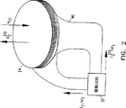
図2は本発明の好ましい一実施形態に従う発信機コイルの概略図である。
図3は本発明の別の好ましい実施形態に従うコイル駆動回路の概略図である。
図4は本発明の好ましい一実施形態に従って目的物を追跡する方法の概略的フローチャート図である。
好ましい実施形態の詳細な説明
図1は本発明の好ましい実施形態に従って動作する、医療用カテーテルのような、プローブ20を追跡するためのシステムを概略的に示している。本明細書に参考文献として含まれるBen-Haimに付与された米国特許第5,391,199号および本出願と出願人を同一にする1995年1月24日出願の未公開国際特許出願第PCT/US95/01103号に記載されるように、このシステムは複数の発信機コイル22,24および26を備えている。これらのコイルはプローブ20の近傍においてそれぞれの周波数ω1,ω2およびω3でそれぞれの磁場H1,H2およびH3を発生する。このプローブはさらにセンサーコイル27,28および29を備えており、これらのセンサーは各磁場に応じて電流信号を発生する。これらの信号はプローブ20の位置および方向によって決まるそれぞれの振幅を有する各周波数ω1,ω2およびω3における成分から構成されている。
このシステムはさらに各発信機コイルに連結する駆動回路30,32および33を備えており、当該回路はコイル22,24および26をそれぞれの駆動周波数ω1,ω2およびω3で駆動する。好ましくは、センサーコイル27,28および29により発生する信号は信号処理回路34によって処理されて、コンピュータ36によりプローブ20の位置および方向の座標を計算するために用いられる。
簡明のために、図1では、3個の発信機コイル22,24および26と3個のセンサーコイル27,28および29がプローブ20内に示されている。しかしながら、本発明が2個,4個またはそれ以上の発信機コイルと1個,2個またはそれ以上のセンサーコイルから成る追跡システムにも同様に適用可能であることが理解されると考える。さらに、本発明は他の種類の目的物の追跡にも使用可能である。
相互インダクタンスの作用が無い場合は、周波数ω1においてセンサーコイル27,28および29により発生される信号は各センサーコイルのそれぞれの軸に沿うプローブ20における場H1による磁束放射(projection)の時間的導関数の振幅に比例する。同様に、周波数ω2およびω3で発生される信号はH2およびH3の放射に比例する。このような単一発信機コイルによる磁場の方向と振幅は当該技術分野において既知の方法により容易に計算できるので、単一の発信機コイルによるセンサーコイル信号を当該発信機コイルに対するセンサーコイルの距離と方向に直接関係付けることが可能になる。
しかしながら、実際は、発信機コイル22により発生される磁場H1はプローブ20の直ぐ近傍の空間内に限られておらず、コイル24および26の近傍においても0でない振幅で存在する。当該技術分野において周知のように(例えば、LorrainおよびCorsonの電磁場および電磁波(Electromagnetic Fields and Waves)第2版、1970年、第343頁〜第345頁参照)、コイル22に流れる電流I1によりコイル24を通る磁束Φ2は、
![]()
![]()
ここで、コイル24のインダクタンスがLでその抵抗値がゼロとすると、コイルにおける全電圧値は、
![]()
駆動回路30および32はコイル22および24のそれぞれの周波数ω1およびω2正弦波電流により当該コイル22および24を駆動するのが好ましいから、以下の式(4)により与えられる振幅を有する付加的な電流I12がコイル24に周波数ω1で流れる。
![]()

従って、例えば、米国特許第5,391,199号および未公開国際特許出願第PCT/US95/01103号に記載されるようなコイル22および24が25ミリの内径と約60ミリの外径を有し互いに39センチの距離で離間する追跡システムにおいては、I12=0.0025(ω1/ω2)I1となり、この値はω1=2ω2の場合に0.5%の誤差になる。従って、周波数ω1においてセンサーコイル27,28および29により発生される信号はH1による位置信号成分とH12による寄生信号成分の両方を含むことになり、このことによって、プローブ20の位置決定において1%までの誤差が生じることになる。さらに、周波数ω1における付加的な寄生信号成分はコイル26と他の発信機コイルのいずれかにおける相互インダクタンスによっても生じる。同様に、周波数ω2およびω3におけるセンサーコイル信号もまた寄生成分を含むことになる。
このため、図2に示す本発明の好ましい実施形態においては、1個以上の調整コイル40が発信機コイル24に近接配置されており、好ましくは、絡み合っている。駆動回路32はコイル24を当該コイルの駆動周波数ω2において電流I2で駆動する。回路32はさらに周波数ω1において電流I2 (1)で調整コイル40を駆動する。この電流I2 (1)は磁場H2 (1)をコイル24の軸に沿って発生し、この磁場は磁場H12に対して振幅が等しく位相が180度ずれている。これにより、相互誘導された電流I12が場H2 (1)により誘導される等しい反対方向の電流によって概ね相殺される。
簡明のため、図2および上述の説明は単一周波数において駆動される単一の調整コイルのみに関するものであるが、本発明の好ましい実施形態においては、コイル22,24および26のそれぞれが少なくとも1個の調整コイルと絡み合っており、適当な電流および周波数で駆動されて他のコイルによる相互誘導される電流を概ね相殺できることが理解されると考える。
図3は本発明の別の好ましい実施形態を概略的に示しており、同実施形態においては、駆動回路32がコイル24を駆動して相互誘導される電流を概ね相殺するように構成されている。すなわち、回路32はコイル24をその駆動周波数ω2で駆動するシステム電流供給源50と、電流アナライザ54により決められた振幅と位相を有し、コイル22および26のそれぞれの周波数ω1およびω3でコイル24を駆動する電流を発生する適応電流供給源52を備えている。この電流アナライザはコイル24における電流を当該技術分野において既知の方法でサンプリングして、そのサンプリングした電流を周波数成分に分離する。さらに、アナライザ54は適応電流供給源52を用いて発生されるω1およびω3の電流の振幅および位相を調節して、コイル24からサンプリングされる電流において周波数ω1およびω3で感知される成分を最小化する。すなわち、一般的に、発生されるω1およびω3の電流は相互誘導電流I12およびI32に対してほぼ同等の振幅で位相が180度ずれている。さらに、コイル22および26もまた同様の適応駆動回路により駆動されることが理解できると考える。
本発明の他の好ましい実施形態においては、信号処理回路34とコンピュータ36が発信機コイル間の相互インダクタンスによりセンサーコイル27,28および29によって発生される寄生信号成分の振幅および位相を決定するように機能して、当該寄生成分を考慮してプローブ20の位置決定を補正する。
このような本発明の好ましい実施形態の一例においては、各コイルによる磁場の振幅および位相は調和検出法によって検出できる。すなわち、この方法によれば、信号をサンプリングして、各信号の一定整数周期、すなわち、2πfs/ω=Nが測定される。この式中、fsはサンプリング周波数であり、Nはサンプリング点の数である。この方法においては、信号サンプリングが磁場の周波数に同期している。すなわち、Nが小さな数であれば、サンプリングは磁場に同期しているのが好ましく、周期的な磁場のピーク値において生じるように同期するのが好ましい。このようにして周波数ωにおいて得られる信号は、
相互インダクタンスの存在下においては、j番目のセンサーコイルにより発生される信号は、発信機コイル周波数ωiにおいて以下のようなそれぞれの振幅UijおよびVijを有する各周波数成分から構成されている。
センサーコイル27,28および29とプローブ20の位置を正確に決定するために、図4に示す方法を用いてコイルから受け取った信号を処理するのが好ましい。最初(60)に、信号を、調和検出法のような当該技術分野において知られる方法を用いて、周波数ω1,ω2およびω3における成分UijおよびVijに分離する。次に、相互インダクタンスの作用が無視できる、すなわち、全てのAijkmがゼロであるとして、これらの信号の振幅Aijを決定(62)する。発信機コイルのみによって決まる位相ψiおよびψikmをそれぞれの発信機コイルの位相を計算することによって導き出す(64)。次いで、振幅Aijを用いてコイル27,28および29の位置および方向を、例えば、未公開国際特許出願第PCT/US95/01103号に記載されるように推定する(66)。
推定した各センサーコイルの位置についてAijkmの理論値を計算する(68)。この計算を行なうために、発信機コイル間の相互インダクタンスにより発生する寄生磁場Hikを各センサーコイルの推定された位置において決定する。これらの寄生磁場は、各センサーコイルの軸に沿う寄生磁場の放射に基づいて、発信機コイルの座標フレームからセンサーコイルの座標フレームに変換される。この場の放射は以下の関係式を用いて各センサーコイルにより発生される寄生信号成分の理論的振幅を計算するために用いられる。
![]()
各センサーコイルの位置における寄生磁場Hikの振幅および方向を決定するために種々の方法を使うことができる。本発明の好ましい一実施形態においては、コイル間の相互インダクタンスおよび結果として生じる磁場を当該技術分野において周知の方法を用いて幾何学的考察に基づいて理論的に計算する。また、別の好ましい実施形態においては、一対の発信機コイルの相互インダクタンスを、当該コイルの一方の駆動回路をその駆動周波数で磁場を発生するように起動して、その周波数において他の一方のコイルに流れる電流を測定することにより決定する。さらに、これらの測定した相互インダクタンスを用いて、上述の説明のように、結果として生じる寄生磁場を計算する。
最後に、式(8)および式(9)に係数Aijkmの理論値を代入して9個のAij成分の補正値を決定し(70)、これらの値を用いてプローブの位置および方向の座標を補正する(72)。上記の工程(68),(70)および(72)はプローブの位置および方向の座標が収斂するまで反復的に繰返されるのが好ましい。
上述の方法は3個の発信機コイルおよび3個のセンサーコイルから成るシステムに基づいて説明したが、本発明の方法はより多数または少数のコイルまたはアンテナを使用する他の電磁式目的物追跡システムにも同等に適用することができる。This application claims the benefit of US Provisional Patent Application No. 60 / 014,084, filed Mar. 26, 1996, which is incorporated herein by reference.
TECHNICAL FIELD OF THE INVENTION
The present invention relates generally to an apparatus for generating and detecting a magnetic field, and more particularly to a non-contact electromagnetic method and apparatus for tracking the position and orientation of an object.
Background of the Invention
Non-contact electromagnetic tracking systems are well known in a wide range of applications in the art. For example, US Pat. No. 4,054,881 describes a tracking system that uses three coils to generate an electromagnetic field near an object. These three generated fields are distinguished from each other by open loop multiplexing of time, frequency or phase. Furthermore, signal currents flowing through the three orthogonal sensor coils are used for determining the position of the object based on the iterative calculation method.
US Pat. No. 5,391,199, filed July 20, 1993, which is hereby incorporated by reference and filed with the applicant of the present application, generates three-dimensional information about medical probes or catheters. The system to do is described. In this case, a sensor coil is placed in the catheter and generates a signal in response to an externally applied magnetic field. These magnetic fields are generated by three radiator coils that are fixed to an external reference frame at known mutually spaced locations. The amplitude of each signal generated according to the field generated by these transmitter coils is detected and used for calculating the position of the sensor coil. Preferably, each transmitter coil is driven by a drive circuit that generates a field at a known frequency separate from the other transmitter coils, so that the signal generated by the sensor coil is a component corresponding to a different transmitter coil. Separated by frequency.
PCT / US95 / 01103, which is an unpublished international patent application filed on January 24, 1995, which is included as a reference in the present specification and filed as the applicant of the present application, has six components related to the catheter tip. A system for generating position and orientation information signals is described. This system uses a position that can be positioned on the catheter, for example, a plurality of non-concentric sensor coils near its tip and a plurality of transmitter coils fixed in an external reference frame. These coils generate signals in response to the magnetic field generated by the transmitter coil, and the signals enable calculation of six types of position and direction coordinate components. As in the case of the above-mentioned '539 patent application, the transmitter coil operates simultaneously at different frequencies, such as 1000 Hz, 2000 Hz, and 3000 Hz.
The tracking system described above relies on separating the position response signal into frequency components, each such component specific to a single transmitter coil at a known location that emits a known narrow band frequency. It seems that it corresponds to. In practice, however, the transmitter coil generates a magnetic field even at frequencies outside the desired bandwidth, for example by mutual induction, and these mutual induction fields determine the position of the object being tracked. An error occurs.
Summary of the Invention
It is an object of the present invention to provide an improved electromagnetic transmitter coil and a driving circuit therefor that are used in an object tracking system in order to increase the object tracking accuracy.
Another object of the present invention is to provide a magnetic field generating coil and a driving circuit attached thereto for generating a field having a narrow bandwidth frequency region.
In one aspect of the invention, the narrowed field bandwidth is achieved by eliminating the mutual inductive action between multiple coils generating fields at different frequencies.
Yet another object of the present invention is to provide a method for improving the position accuracy determined by the object tracking system by position correction taking account of the mutual induction effect.
In a preferred embodiment of the present invention, a plurality of transmitter coils generate magnetic fields at a plurality of different drive frequencies.
In a preferred embodiment of the invention, one or more additional adjustment coils are provided in the vicinity of each transmitter coil. Preferably, these adjustment coils are interwound with the windings of the transmitter coil. The adjustment coil of each transmitter coil is driven by a drive circuit to generate a magnetic field in the opposite direction to the magnetic field component induced along the axis of the transmitter coil by other transmitter coils that are approximately equal in amplitude and frequency.
In another preferred embodiment of the present invention, a drive circuit is associated with each coil for generating drive current therein. This current is composed of a main component at a specific drive frequency of the coil and a secondary component at another frequency corresponding to each coil. These secondary components are approximately equal in amplitude and frequency, and are 180 degrees out of phase with the current induced in the corresponding coil by the magnetic field generated by the other transmitter coil, resulting in the induced current. The effect can be almost offset.
In one example of such a preferred embodiment of the present invention, the drive circuit comprises a sensing device that measures the amplitude, frequency and phase of the induced current in a particular coil. The drive circuit further comprises an adaptive current source, which receives the amplitude, frequency and phase data measured by the sensing device and offsets the out-of-phase secondary current component in order to cancel the effect of the induced current. Is generated.
In yet another embodiment of the present invention, the drive circuit includes an ideal current source, and the device functions to maintain a constant current at that particular drive frequency in each coil.
In another preferred embodiment of the present invention, the object tracking system comprises one or more sensor coils proximate to a positionable point on the object being tracked and a plurality of transmitter coils, When the transmitter coil is driven by the drive circuit, a magnetic field is generated at different driving frequencies in the vicinity of the object. The sensor coils generate signals according to their magnetic fields, and these signals are received by a signal processing circuit and analyzed by a processing device such as a computer. These signals include a position signal component corresponding to the magnetic field generated from the coil at the driving frequency of each transmitter coil and a parasitic signal component corresponding to the magnetic field generated by mutual induction between the transmitter coils. The computer preferably separates the position signal component from the parasitic signal component by signal processing using an iterative method as described below, and uses the position signal component for position determination of the object.
In one example of such a preferred embodiment of the present invention, a signal containing a position component and a parasitic component is used to approximate the position and orientation coordinates of the object. Next, the strength of the magnetic field generated at that position by the transmitter coil due to the mutual induction between the coils is theoretically calculated and used to determine the theoretical strength of the parasitic component. A corrected signal is then obtained by subtracting the theoretical parasitic component intensity from the original signal, and these corrected signals are used to calculate the corrected position and orientation of the object. These steps are iteratively repeated until the corrected position and orientation converge.
In a preferred embodiment of the present invention, the mutual inductance between transmitter coils in the object tracking system can be determined by empirical measurement methods using methods known in the art. For example, the mutual inductance of a pair of transmitter coils is determined by driving the drive circuit of the first coil to generate a magnetic field at its constant drive frequency and then measuring the current flowing through the second coil. The Thereafter, the theoretical intensity of the parasitic component is calculated using these mutual inductances, and the correction signal is calculated according to the above-described method. Further, the drive circuit is controlled using the mutual inductance determined as described above to generate a drive current that is 180 degrees out of phase with the mutually induced current.
Therefore, according to a preferred embodiment of the present invention, an apparatus for generating a magnetic field composed of a plurality of transmitter coils and a driving circuit connected thereto can be provided, and the driving circuit drives the coils to generate a plurality of driving frequencies. To generate a magnetic field and each transmitter coil generates a field at approximately a single drive frequency.
Preferably, the apparatus for generating the magnetic field generally generates a magnetic field that is attached to at least one of the plurality of transmitter coils and that the at least one coil generates according to the magnetic field generated by the other coils. A circuit for erasing is provided.
Preferably, the circuit for erasing the magnetic field includes one or more adjustment coils, and the adjustment coils are intertwined with at least one of the plurality of transmitter coils. Furthermore, the drive circuit preferably drives one of the one or more adjustment coils attached to at least one of the plurality of transmitter coils at each of the other drive frequencies of the plurality of transmitter coils. .
Preferably, the circuit for erasing the magnetic field includes an adaptive current supply source, and the current supply source is at least one of the plurality of transmitter coils and the other one of the plurality of transmitter coils. A current is generated at each driving frequency.
Preferably, the circuit further comprises a current analyzer coupled to the adaptive current source, the current analyzer being in at least one of the plurality of transmitter coils and the other one of the plurality of transmitter coils. The parasitic current flowing at each drive frequency is measured, and the parasitic current is minimized by adjusting the generated current using the adaptive current source.
Furthermore, according to an example of a preferred embodiment of the present invention, a method for generating a magnetic field having a desired narrow frequency bandwidth can be provided, the method comprising driving a transmitter coil with current at a desired frequency; Analyzing the current flowing in the coil to measure one or more induced frequency induced current components and adaptively driving the transmitter coil with the one or more unwanted frequency corrected current components The correction current component has substantially the same amplitude and opposite phase with respect to the induced current component at each of one or more undesired frequencies.
In addition, according to an example of a preferred embodiment of the present invention, a method for tracking an object can be provided, and the method includes a plurality of desired narrow frequency bandwidths in the vicinity of the object to be tracked according to the method. A step of generating a plurality of magnetic fields respectively, a step of arranging one or more sensor coils in a positionable position on the object, a step of receiving a signal generated by each sensor coil in response to the magnetic field; And analyzing the signal to determine the coordinates of the position and direction of the object.
Furthermore, according to an example of a preferred embodiment of the present invention, a method for tracking an object can be provided, the method driving and tracking a plurality of transmitter coils with currents at a plurality of frequencies, respectively. Generating a magnetic field in the vicinity of, positioning one or more sensor coils in a positionable position on the object, receiving a signal generated by each sensor coil in response to the magnetic field, Analyzing the signal to determine the coordinates of the uncorrected position and direction of the object, and correcting the coordinates of the position and direction in consideration of errors due to mutual inductance between the plurality of transmitter coils. Become.
Preferably, the coordinates of the position and the direction include a step of determining a parasitic magnetic field generated at an uncorrected position of the object by mutual inductance, and a parasitic signal component generated by each sensor coil according to the parasitic magnetic field. A step of calculating, a step of calculating a signal corrected by subtracting a parasitic signal component from a signal received from each sensor coil, and analyzing the corrected signal to determine coordinates of the corrected position and direction. It is corrected by the process.
Preferably, the step of determining the parasitic magnetic field includes a step of measuring an induced current component of an undesired frequency by analyzing currents flowing through a plurality of transmitter coils.
The step of determining the parasitic magnetic field includes a step of theoretically calculating the mutual inductance between the plurality of transmitter coils.
Thus, according to an example of a preferred embodiment of the present invention, an apparatus for generating a magnetic field can be provided,
A plurality of transmitter coils;
A drive circuit connected to these is provided, the drive circuit drives each coil to generate a magnetic field at a plurality of drive frequencies,
Each of the plurality of transmitter coils generates a field at approximately a single drive frequency.
Preferably, the apparatus includes a circuit attached to at least one of the plurality of transmitter coils, and the circuit generates a magnetic field generated by the at least one coil according to a field generated by the other coils. Erasing mostly. The circuit preferably includes one or more adjustment coils, which are intertwined with at least one of the plurality of coils.
Preferably, the drive circuit further drives one of the one or more adjustment coils attached to at least one of the plurality of transmitter coils at each of the other drive frequencies of the plurality of transmitter coils.
Preferably, the circuit for erasing includes an adaptive current supply source, and the current supply source is at least one of the plurality of transmitter coils, and each of the other driving frequencies of the plurality of transmitter coils. Generates current.
Preferably, the circuit for erasing further comprises a current analyzer coupled to the adaptive current supply source, the current analyzer being the other of the plurality of transmitter coils in at least one of the plurality of transmitter coils. The parasitic current flowing at each driving frequency is measured, and the parasitic current is minimized by adjusting the current generated using the adaptive current supply source.
Preferably, the drive circuit is configured to maintain a constant current at each single drive frequency in each of the plurality of transmitter coils.
Furthermore, according to an example of a preferred embodiment of the present invention, a method for generating a magnetic field having a desired narrow frequency bandwidth can be provided, the method comprising:
Driving one transmitter coil with current at a constant frequency in a desired narrow frequency bandwidth;
Analyzing the current flowing in the coil to measure current components induced at one or more undesired frequencies;
Adaptively driving the transmitter coil with the correction current of the one or more undesired frequencies, and the correction current component is measured with respect to the induced current component measured at the one or more undesired frequencies. The amplitude is almost the same, but the phase is opposite.
In addition, according to an example of a preferred embodiment of the present invention, a method for tracking an object can be provided, and the method includes a plurality of desired narrow frequency bandwidths in the vicinity of the object to be tracked according to the method. Generating a plurality of magnetic fields each having;
Placing one or more sensor coils in a positionable position on the object;
Receiving a signal generated by each sensor coil in response to the magnetic field;
And analyzing the signal to determine the coordinates of the position and direction of the object.
Furthermore, according to an example of a preferred embodiment of the present invention, a method for tracking an object can be provided, the method comprising:
Generating a magnetic field in the vicinity of an object that drives and tracks each of a plurality of transmitter coils with currents at a plurality of frequencies;
Placing one or more sensor coils in a positionable position on the object;
Receiving a signal generated by each sensor coil in response to the magnetic field;
Analyzing the signal to determine the uncorrected position and orientation coordinates of the object;
And correcting the coordinates of the position and direction in consideration of errors due to mutual inductance between the plurality of transmitter coils.
Preferably, the coordinates of the position and direction are
Determining a parasitic magnetic field generated at an uncorrected position of the object by mutual inductance;
Calculating a parasitic signal component generated by each sensor coil according to the parasitic magnetic field;
Calculating a corrected signal by subtracting the parasitic signal component from the signal received from each sensor coil;
The correction is performed by analyzing the corrected signal and determining the coordinates of the corrected position and direction.
Preferably, the parasitic magnetic field is determined by analyzing currents flowing through the plurality of transmitter coils and measuring an induced current component having an undesired frequency.
The parasitic magnetic field is determined by theoretically calculating the mutual inductance between the plurality of transmitter coils.
[Brief description of the drawings]
The following preferred embodiments of the present invention will be described in detail with reference to the accompanying drawings.
FIG. 1 is a schematic diagram of an object tracking system operating in accordance with a preferred embodiment of the present invention.
FIG. 2 is a schematic diagram of a transmitter coil according to a preferred embodiment of the present invention.
FIG. 3 is a schematic diagram of a coil drive circuit according to another preferred embodiment of the present invention.
FIG. 4 is a schematic flowchart diagram of a method for tracking an object according to a preferred embodiment of the present invention.
Detailed Description of the Preferred Embodiment
FIG. 1 schematically illustrates a system for tracking a
The system further comprises drive
For simplicity, in FIG. 1, three
When there is no mutual inductance, frequency ω1The signals generated by the sensor coils 27, 28 and 29 in FIG.1Is proportional to the amplitude of the temporal derivative of the flux radiation projection. Similarly, the frequency ω2And ωThreeThe signal generated at is H2And HThreeIs proportional to the radiation. Since the direction and amplitude of the magnetic field generated by such a single transmitter coil can be easily calculated by a method known in the art, the sensor coil signal generated by a single transmitter coil can be expressed as the distance between the sensor coil and the transmitter coil. It becomes possible to directly relate to the direction.
However, in practice, the magnetic field H generated by the transmitter coil 221Is not limited to the space in the immediate vicinity of the
![]()
![]()
Here, if the inductance of the
![]()
The
![]()
Thus, for example, coils 22 and 24 as described in US Pat. No. 5,391,199 and unpublished international patent application PCT / US95 / 01103 have an inner diameter of 25 mm and an outer diameter of about 60 mm. In tracking systems that are 39 centimeters away from each other, I12= 0.0025 (ω1/ Ω2) I1And this value is ω1= 2ω2In this case, the error is 0.5%. Therefore, the frequency ω1The signals generated by the sensor coils 27, 28 and 29 in FIG.1Position signal component and H12This will result in up to 1% error in determining the position of the
For this reason, in the preferred embodiment of the present invention shown in FIG. 2, one or more adjustment coils 40 are located close to the
For simplicity, FIG. 2 and the above description relate only to a single conditioning coil driven at a single frequency, but in the preferred embodiment of the present invention, each of the
FIG. 3 schematically illustrates another preferred embodiment of the present invention, in which the
In another preferred embodiment of the present invention, the
In an example of such a preferred embodiment of the present invention, the amplitude and phase of the magnetic field generated by each coil can be detected by a harmonic detection method. That is, according to this method, a signal is sampled, and a constant integer period of each signal, that is, 2πfs/ Ω = N is measured. Where fsIs the sampling frequency and N is the number of sampling points. In this method, signal sampling is synchronized to the magnetic field frequency. That is, if N is a small number, sampling is preferably synchronized to the magnetic field, and preferably to occur at the peak value of the periodic magnetic field. The signal thus obtained at frequency ω is
In the presence of mutual inductance, the signal generated by the jth sensor coil is the transmitter coil frequency ω.iIn FIG. 1, each frequency component has the following amplitudes Uij and Vij.
In order to accurately determine the positions of the sensor coils 27, 28 and 29 and the
Aijk for the estimated position of each sensor coilmThe theoretical value of is calculated (68). In order to perform this calculation, the parasitic magnetic field Hik generated by the mutual inductance between the transmitter coils is determined at the estimated position of each sensor coil. These parasitic magnetic fields are converted from the coordinate frame of the transmitter coil to the coordinate frame of the sensor coil based on the radiation of the parasitic magnetic field along the axis of each sensor coil. This field radiation is used to calculate the theoretical amplitude of the parasitic signal component generated by each sensor coil using the following relation:
![]()
Various methods can be used to determine the amplitude and direction of the parasitic magnetic field Hik at the position of each sensor coil. In a preferred embodiment of the present invention, the mutual inductance between the coils and the resulting magnetic field are theoretically calculated based on geometric considerations using methods well known in the art. In another preferred embodiment, the mutual inductance of the pair of transmitter coils is activated so that one drive circuit of the coils generates a magnetic field at the drive frequency, and the other coil at that frequency is activated. It is determined by measuring the current flowing through. In addition, these measured mutual inductances are used to calculate the resulting parasitic magnetic field as described above.
Finally, Equation (8) and Equation (9) add coefficients AijkmThe correction values of the nine Aij components are determined by substituting these theoretical values (70), and the coordinates of the probe position and direction are corrected using these values (72). The above steps (68), (70) and (72) are preferably repeated iteratively until the probe position and orientation coordinates converge.
While the above method has been described based on a system consisting of three transmitter coils and three sensor coils, the method of the present invention is applicable to other electromagnetic object tracking systems that use more or fewer coils or antennas. It can be equally applied to.
Claims (15)
複数の発信機コイルと、
前記発信機コイルに連結されて、複数の駆動周波数で磁場を発生するように当該コイルを駆動する駆動回路であって、前記複数の発信機コイルのそれぞれは、当該駆動回路の駆動により単一で個別の駆動周波数において磁場を発生させる、駆動回路と、
前記複数の発信機コイルの少なくとも1個に付属して、その他のコイルにより発生される磁場に応じて当該少なくとも1個のコイルにより発生される磁場を概ね消去するための回路と、
を具備する装置。 In an apparatus for tracking an object by generating a magnetic field,
A plurality of transmitter coils;
It is connected to the transmitter coil, a driving circuit for driving the coils to generate a magnetic field at a plurality of driving frequencies, each of the plurality of transmitters coil, a single by driving of the drive circuit make generate magnetic fields in a separate driving frequency, a driving circuit,
Comes to at least one of said plurality of transmitters coil, a circuit for substantially erasing magnetic field generated by the at least one coil in response to magnetic fields generated by the other coils,
A device comprising:
前記消去するための回路は1個以上の調整コイルを備える、装置。 The apparatus of claim 1.
Circuitry for said erasing comprises one or more of the adjustment coil device.
前記1個以上の調整コイルは前記複数の発信機コイルの少なくとも1個と絡み合っている、装置。 The apparatus of claim 2.
It said one or more adjustment coil is intertwined with at least one of said plurality of transmitters coil device.
前記駆動回路が、前記複数の発信機コイルの少なくとも1個に付属する前記1個以上の調整コイルの1個を前記複数の発信機コイルの他の1個における個別の駆動周波数においてさらに駆動する、装置。 The apparatus of claim 3.
Said drive circuit further drives the individual driving frequency of one of said one or more adjustment coils that comes to at least one of the previous SL plurality of transmitters coil in the other one of said plurality of transmitters coil , Equipment.
前記消去するための回路は適応電流供給源を含む、装置。 The apparatus according to claim 4.
Circuitry for said erasing comprises an adaptive current supply, device.
前記適応電流供給源は、前記複数の発信機コイルの少なくとも1個に前記複数の発信機コイルの他の1個における個別の駆動周波数において電流を発生させる、装置。 The apparatus of claim 5.
The adaptive current source, causes generating an electric current in the individual driving frequency of another one of said plurality of transmitters coil to at least one of said plurality of transmitters coil device.
前記消去するための回路は、前記適応電流供給源に連結された電流アナライザをさらに含む、装置。 The apparatus of claim 6.
Circuitry for said erasure further comprises a current analyzer coupled to the front Symbol adaptive current supply, device.
前記電流アナライザは、前記複数の発信機コイルの少なくとも1個に前記複数の発信機コイルの他の1個における個別の駆動周波数において流れる寄生電流を測定して、前記適応電流供給源が発生させる電流を調節することにより当該寄生電流を最小にする、装置。 The apparatus of claim 7.
The current analyzer measures parasitic currents flowing in the individual driving frequency of another one of said plurality of transmitters coil to at least one of said plurality of transmitter coils, wherein the adaptive current current sources causes generation to the parasitic current to a minimum by adjusting the apparatus.
前期駆動回路は、前記複数の発信機コイルの各々においてその単一で個別の駆動周波数における一定電流を維持する、装置。 The apparatus of claim 1.
Year driving circuit maintains a constant current in the individual driving frequency at its single in each of the plurality of transmitters coil device.
所望の狭い周波数帯域幅において所与の周波数における電流で1個の発信機コイルを駆動する工程と、
1個以上の不所望の周波数において誘導された電流成分を測定するために前記コイル中に流れる電流を解析する工程と、
前記発信機コイルを前記1個以上の不所望周波数の補正電流で適応駆動する工程であって、当該補正電流成分は前記1個以上のそれぞれの不所望周波数において測定される誘導電流成分に対して振幅がほぼ同じであるが位相が反対である、工程と、
を具備する方法。 In a method for tracking an object by generating a magnetic field having a desired narrow frequency bandwidth,
Driving one transmitter coil with current at a given frequency in a desired narrow frequency bandwidth;
Analyzing the current flowing in the coil to measure current components induced at one or more undesired frequencies;
A process for adapting driving the transmitter coil at the one or more undesired frequencies of the correction current, which induced current component the correction current components to be measured in the one or more respective undesired frequency A process with substantially the same amplitude but opposite phase ;
A method comprising :
追跡する目的物の近傍に複数で個別の所望の狭い周波数帯域幅を有する複数の磁場を発生させる工程と、
目的物上の位置決め可能な部位に1個以上のセンサーコイルを配置する工程と、
前記磁場に応じて各センサーコイルにより発生された信号を受け取る工程と、
前記信号を解析して目的物の位置および方向の座標を決定する工程と、
を具備する方法。 Oite to the method described in 請 Motomeko 10,
A step of causing generating a plurality of magnetic field have a separate desired narrow frequency bandwidth in a plurality in the vicinity of the object to be tracked,
Placing one or more sensor coils in a positionable position on the object;
Receiving a signal generated by each sensor coil in response to the magnetic field;
Analyzing the signal to determine the position and orientation coordinates of the object ;
A method comprising :
複数で個別の周波数における電流で複数の発信機コイルを駆動して追跡する目的物の近傍に磁場を発生させる工程と、
目的物上の位置決め可能な部位に1個以上のセンサーコイルを配置する工程と、
前記磁場に応じて各センサーコイルにより発生された信号を受け取る工程と、
前記信号を解析して目的物の未補正の位置および方向の座標を決定する工程と、
前記複数の発信機コイル間の相互インダクタンスによる誤差を考慮して当該位置および方向の座標を補正する工程と、
を具備する方法。 In a method for tracking an object,
A step of causing generating a magnetic field in the vicinity of the object to be tracked driving dynamic multiple transmitters coil current in discrete frequency in a plurality,
Placing one or more sensor coils in a positionable position on the object;
Receiving a signal generated by each sensor coil in response to the magnetic field;
Analyzing the signal to determine the uncorrected position and orientation coordinates of the object;
Correcting the coordinates of the position and direction in consideration of errors due to mutual inductance between the plurality of transmitter coils ;
A method comprising :
前記位置および方向の座標を補正する工程は、
相互インダクタンスにより目的物の未補正の位置において発生される寄生磁場を決定する工程と、
前記寄生磁場に応じて各センサーコイルにより発生される寄生信号成分を計算する工程と、
各センサーコイルから受け取った信号から前記寄生信号成分を差し引くことにより補正された信号を計算する工程と、
前記補正された信号を解析して補正された位置および方向の座標を決定する工程と、
を具備する方法。 The method of claim 12, wherein
The step of correcting the coordinates of the position and direction includes:
Determining a parasitic magnetic field generated at an uncorrected position of the object by mutual inductance;
Calculating a parasitic signal component generated by each sensor coil according to the parasitic magnetic field;
Calculating a corrected signal by subtracting the parasitic signal component from the signal received from each sensor coil;
Analyzing the corrected signal to determine corrected position and orientation coordinates ;
A method comprising :
前記寄生磁場を決定する工程は、複数の発信機コイルに流れる電流を解析して不所望周波数における誘導電流成分を測定することを含む、方法。 The method of claim 13, wherein
Wherein the step of determining the parasitic field includes analyzing the current flowing through the plurality of transmitter coil to measure the induced current components at unwanted frequencies, methods.
前記寄生磁場を決定する工程は、複数の発信機コイル間の相互インダクタンスを理論的に計算することを含む、方法。 The method of claim 13, wherein
The step of determining the parasitic field includes calculating the mutual inductance between the plurality of transmitters coil theoretically method.
Applications Claiming Priority (3)
| Application Number | Priority Date | Filing Date | Title |
|---|---|---|---|
| US1408496P | 1996-03-26 | 1996-03-26 | |
| US60/014,084 | 1996-03-26 | ||
| PCT/IL1997/000100 WO1997036143A1 (en) | 1996-03-26 | 1997-03-18 | Mutual induction correction |
Publications (3)
| Publication Number | Publication Date |
|---|---|
| JP2000508067A JP2000508067A (en) | 2000-06-27 |
| JP2000508067A5 JP2000508067A5 (en) | 2004-12-02 |
| JP4141502B2 true JP4141502B2 (en) | 2008-08-27 |
Family
ID=21763453
Family Applications (1)
| Application Number | Title | Priority Date | Filing Date |
|---|---|---|---|
| JP53420497A Expired - Lifetime JP4141502B2 (en) | 1996-03-26 | 1997-03-18 | Apparatus and method for tracking objects |
Country Status (8)
| Country | Link |
|---|---|
| EP (1) | EP0892908B1 (en) |
| JP (1) | JP4141502B2 (en) |
| AU (1) | AU715167B2 (en) |
| CA (1) | CA2249982C (en) |
| DE (1) | DE69721985T2 (en) |
| ES (1) | ES2200161T3 (en) |
| IL (1) | IL126286A (en) |
| WO (1) | WO1997036143A1 (en) |
Families Citing this family (29)
| Publication number | Priority date | Publication date | Assignee | Title |
|---|---|---|---|---|
| US6147480A (en) * | 1997-10-23 | 2000-11-14 | Biosense, Inc. | Detection of metal disturbance |
| JP2003524443A (en) | 1998-08-02 | 2003-08-19 | スーパー ディメンション リミテッド | Medical guidance device |
| EP1873545A3 (en) * | 1998-12-23 | 2008-02-13 | Peter D. Jakab | Magnetic resonance scanner with electromagnetic position and orientation tracking device |
| IL143909A0 (en) | 1998-12-23 | 2002-04-21 | Jakab Peter D | Magnetic resonance scanner with electromagnetic position and orientation tracking device |
| US6498477B1 (en) * | 1999-03-19 | 2002-12-24 | Biosense, Inc. | Mutual crosstalk elimination in medical systems using radiator coils and magnetic fields |
| US6233476B1 (en) | 1999-05-18 | 2001-05-15 | Mediguide Ltd. | Medical positioning system |
| US9572519B2 (en) | 1999-05-18 | 2017-02-21 | Mediguide Ltd. | Method and apparatus for invasive device tracking using organ timing signal generated from MPS sensors |
| US9833167B2 (en) | 1999-05-18 | 2017-12-05 | Mediguide Ltd. | Method and system for superimposing virtual anatomical landmarks on an image |
| US7778688B2 (en) | 1999-05-18 | 2010-08-17 | MediGuide, Ltd. | System and method for delivering a stent to a selected position within a lumen |
| US6484118B1 (en) * | 2000-07-20 | 2002-11-19 | Biosense, Inc. | Electromagnetic position single axis system |
| US7809421B1 (en) * | 2000-07-20 | 2010-10-05 | Biosense, Inc. | Medical system calibration with static metal compensation |
| JP4880264B2 (en) * | 2005-08-24 | 2012-02-22 | オリンパス株式会社 | POSITION DETECTION DEVICE AND MEDICAL DEVICE POSITION DETECTION SYSTEM |
| US8000772B2 (en) * | 2005-10-19 | 2011-08-16 | Biosense Webster, Inc. | Metal immunity in a reverse magnetic system |
| US8798711B2 (en) * | 2006-02-09 | 2014-08-05 | Biosense Webster, Inc. | Shielding of catheter handle |
| US7860553B2 (en) * | 2006-02-09 | 2010-12-28 | Biosense Webster, Inc. | Two-stage calibration of medical probes |
| US8473030B2 (en) * | 2007-01-12 | 2013-06-25 | Medtronic Vascular, Inc. | Vessel position and configuration imaging apparatus and methods |
| US9575140B2 (en) | 2008-04-03 | 2017-02-21 | Covidien Lp | Magnetic interference detection system and method |
| EP2297673B1 (en) | 2008-06-03 | 2020-04-22 | Covidien LP | Feature-based registration method |
| US8218847B2 (en) | 2008-06-06 | 2012-07-10 | Superdimension, Ltd. | Hybrid registration method |
| US9018935B2 (en) | 2011-09-19 | 2015-04-28 | Mettler-Toledo Safeline Limited | Method for operating a metal detection apparatus and apparatus |
| JP2017527327A (en) | 2014-07-03 | 2017-09-21 | セント・ジュード・メディカル・インターナショナル・ホールディング・エスエーアールエルSt. Jude Medical International Holding S.a,r.l. | Local magnetic field generator |
| US10751126B2 (en) | 2016-10-28 | 2020-08-25 | Covidien Lp | System and method for generating a map for electromagnetic navigation |
| US10517505B2 (en) | 2016-10-28 | 2019-12-31 | Covidien Lp | Systems, methods, and computer-readable media for optimizing an electromagnetic navigation system |
| US10418705B2 (en) | 2016-10-28 | 2019-09-17 | Covidien Lp | Electromagnetic navigation antenna assembly and electromagnetic navigation system including the same |
| US10722311B2 (en) | 2016-10-28 | 2020-07-28 | Covidien Lp | System and method for identifying a location and/or an orientation of an electromagnetic sensor based on a map |
| US10615500B2 (en) | 2016-10-28 | 2020-04-07 | Covidien Lp | System and method for designing electromagnetic navigation antenna assemblies |
| US10446931B2 (en) | 2016-10-28 | 2019-10-15 | Covidien Lp | Electromagnetic navigation antenna assembly and electromagnetic navigation system including the same |
| US10638952B2 (en) | 2016-10-28 | 2020-05-05 | Covidien Lp | Methods, systems, and computer-readable media for calibrating an electromagnetic navigation system |
| US10792106B2 (en) | 2016-10-28 | 2020-10-06 | Covidien Lp | System for calibrating an electromagnetic navigation system |
Family Cites Families (3)
| Publication number | Priority date | Publication date | Assignee | Title |
|---|---|---|---|---|
| NL8801077A (en) * | 1988-04-26 | 1989-11-16 | Philips Nv | MAGNETIC RESONANCE DEVICE WITH DISCONNECTED RF COILS. |
| US5068608A (en) * | 1989-10-30 | 1991-11-26 | Westinghouse Electric Corp. | Multiple coil eddy current probe system and method for determining the length of a discontinuity |
| DE4300529C2 (en) * | 1993-01-12 | 1995-07-13 | Andreas Zierdt | Method and device for determining the spatial arrangement of a direction-sensitive magnetic field sensor |
-
1997
- 1997-03-18 AU AU20414/97A patent/AU715167B2/en not_active Expired
- 1997-03-18 IL IL12628697A patent/IL126286A/en not_active IP Right Cessation
- 1997-03-18 JP JP53420497A patent/JP4141502B2/en not_active Expired - Lifetime
- 1997-03-18 EP EP97908474A patent/EP0892908B1/en not_active Expired - Lifetime
- 1997-03-18 CA CA002249982A patent/CA2249982C/en not_active Expired - Lifetime
- 1997-03-18 ES ES97908474T patent/ES2200161T3/en not_active Expired - Lifetime
- 1997-03-18 WO PCT/IL1997/000100 patent/WO1997036143A1/en active IP Right Grant
- 1997-03-18 DE DE69721985T patent/DE69721985T2/en not_active Expired - Lifetime
Also Published As
| Publication number | Publication date |
|---|---|
| CA2249982A1 (en) | 1997-10-02 |
| EP0892908A4 (en) | 2000-09-27 |
| CA2249982C (en) | 2008-10-14 |
| JP2000508067A (en) | 2000-06-27 |
| AU2041497A (en) | 1997-10-17 |
| IL126286A (en) | 2001-11-25 |
| AU715167B2 (en) | 2000-01-20 |
| EP0892908B1 (en) | 2003-05-14 |
| EP0892908A1 (en) | 1999-01-27 |
| DE69721985D1 (en) | 2003-06-18 |
| DE69721985T2 (en) | 2004-05-19 |
| IL126286A0 (en) | 1999-05-09 |
| WO1997036143A1 (en) | 1997-10-02 |
| ES2200161T3 (en) | 2004-03-01 |
Similar Documents
| Publication | Publication Date | Title |
|---|---|---|
| JP4141502B2 (en) | Apparatus and method for tracking objects | |
| US6177792B1 (en) | Mutual induction correction for radiator coils of an objects tracking system | |
| US6498477B1 (en) | Mutual crosstalk elimination in medical systems using radiator coils and magnetic fields | |
| KR100830853B1 (en) | Metal immune system | |
| JP4585637B2 (en) | Metal interference detection | |
| US7292948B2 (en) | Magnetic position and orientation measurement system with eddy current distortion compensation | |
| JP4684590B2 (en) | Detection of metal interference in magnetic tracking devices. | |
| JP4717341B2 (en) | Dynamic metal compensation | |
| US8283921B2 (en) | Magnetoresistance sensors for position and orientation determination | |
| US8326402B2 (en) | Distortion-immune position tracking using frequency extrapolation | |
| KR20060023960A (en) | Method for detection and compensation of eddy currents | |
| JP2002228406A5 (en) | ||
| US10101179B2 (en) | Electromagnetic position tracking system |
Legal Events
| Date | Code | Title | Description |
|---|---|---|---|
| A521 | Request for written amendment filed |
Free format text: JAPANESE INTERMEDIATE CODE: A523 Effective date: 20040317 |
|
| A621 | Written request for application examination |
Free format text: JAPANESE INTERMEDIATE CODE: A621 Effective date: 20040317 |
|
| A131 | Notification of reasons for refusal |
Free format text: JAPANESE INTERMEDIATE CODE: A131 Effective date: 20070116 |
|
| A977 | Report on retrieval |
Free format text: JAPANESE INTERMEDIATE CODE: A971007 Effective date: 20061226 |
|
| A601 | Written request for extension of time |
Free format text: JAPANESE INTERMEDIATE CODE: A601 Effective date: 20070416 |
|
| A602 | Written permission of extension of time |
Free format text: JAPANESE INTERMEDIATE CODE: A602 Effective date: 20070604 |
|
| A521 | Request for written amendment filed |
Free format text: JAPANESE INTERMEDIATE CODE: A523 Effective date: 20070717 |
|
| A131 | Notification of reasons for refusal |
Free format text: JAPANESE INTERMEDIATE CODE: A131 Effective date: 20070911 |
|
| A601 | Written request for extension of time |
Free format text: JAPANESE INTERMEDIATE CODE: A601 Effective date: 20071203 |
|
| RD04 | Notification of resignation of power of attorney |
Free format text: JAPANESE INTERMEDIATE CODE: A7424 Effective date: 20071128 |
|
| A602 | Written permission of extension of time |
Free format text: JAPANESE INTERMEDIATE CODE: A602 Effective date: 20080121 |
|
| A711 | Notification of change in applicant |
Free format text: JAPANESE INTERMEDIATE CODE: A712 Effective date: 20080207 |
|
| A521 | Request for written amendment filed |
Free format text: JAPANESE INTERMEDIATE CODE: A523 Effective date: 20080311 |
|
| TRDD | Decision of grant or rejection written | ||
| A01 | Written decision to grant a patent or to grant a registration (utility model) |
Free format text: JAPANESE INTERMEDIATE CODE: A01 Effective date: 20080513 |
|
| A01 | Written decision to grant a patent or to grant a registration (utility model) |
Free format text: JAPANESE INTERMEDIATE CODE: A01 |
|
| A61 | First payment of annual fees (during grant procedure) |
Free format text: JAPANESE INTERMEDIATE CODE: A61 Effective date: 20080611 |
|
| FPAY | Renewal fee payment (event date is renewal date of database) |
Free format text: PAYMENT UNTIL: 20110620 Year of fee payment: 3 |
|
| R150 | Certificate of patent or registration of utility model |
Free format text: JAPANESE INTERMEDIATE CODE: R150 |
|
| FPAY | Renewal fee payment (event date is renewal date of database) |
Free format text: PAYMENT UNTIL: 20110620 Year of fee payment: 3 |
|
| FPAY | Renewal fee payment (event date is renewal date of database) |
Free format text: PAYMENT UNTIL: 20120620 Year of fee payment: 4 |
|
| FPAY | Renewal fee payment (event date is renewal date of database) |
Free format text: PAYMENT UNTIL: 20120620 Year of fee payment: 4 |
|
| FPAY | Renewal fee payment (event date is renewal date of database) |
Free format text: PAYMENT UNTIL: 20130620 Year of fee payment: 5 |
|
| R250 | Receipt of annual fees |
Free format text: JAPANESE INTERMEDIATE CODE: R250 |
|
| R250 | Receipt of annual fees |
Free format text: JAPANESE INTERMEDIATE CODE: R250 |
|
| R250 | Receipt of annual fees |
Free format text: JAPANESE INTERMEDIATE CODE: R250 |
|
| EXPY | Cancellation because of completion of term |