JP4139916B2 - Ultrasonic irradiation method and ultrasonic irradiation apparatus - Google Patents
Ultrasonic irradiation method and ultrasonic irradiation apparatus Download PDFInfo
- Publication number
- JP4139916B2 JP4139916B2 JP2002194791A JP2002194791A JP4139916B2 JP 4139916 B2 JP4139916 B2 JP 4139916B2 JP 2002194791 A JP2002194791 A JP 2002194791A JP 2002194791 A JP2002194791 A JP 2002194791A JP 4139916 B2 JP4139916 B2 JP 4139916B2
- Authority
- JP
- Japan
- Prior art keywords
- frequency
- ultrasonic
- bubbles
- predetermined time
- ultrasonic wave
- Prior art date
- Legal status (The legal status is an assumption and is not a legal conclusion. Google has not performed a legal analysis and makes no representation as to the accuracy of the status listed.)
- Expired - Fee Related
Links
Images


Description
【0001】
【発明の属する技術分野】
本発明は、周囲の少なくとも一部に液体が存在する対象物に向けて超音波を照射する方法に関する。また、本発明は、設定される周波数情報に基づく周波数の超音波を対象物に照射することができる超音波照射装置に関する。
【0002】
【従来の技術】
近年、手術後の患者の生活の質(Quality Of Life :QOL)を向上することが望まれている。このような流れの中で、最小侵襲治療(Minimally Invasive Treatment:MIT)が注目されている。特に、体外から強力超音波等によって形成される衝撃波を結石に照射して無侵襲的に結石を破砕する体外衝撃波結石破砕術(Extracorporeal Shock Wave Lithotripsy :ESWL)による結石破砕装置の検討は1980年代からなされ、医療の現場において実用化されている。腎臓結石、尿路結石及び胆石は、菜食主義者や途上国に患者数が少なく、先進国に患者が多いことを考えれば、動物性蛋白質摂取による現代病のひとつであると考えられる。結石の種類はシュウ酸カルシウムの2水和物もしくは1水和物による結石、燐酸カルシウム結石、感染結石、尿酸による結石、またはシスチン結石等がある。胆石には、コレステロール胆石、色素胆石(カルシウム化合物)等がある。このうち、カルシウム化合物による結石は結石全体の約90%を占め、これらカルシウム化合物を破砕することが結石破砕装置の大きな目標となる。また、破砕されにくいものとしては、最も硬い結石とされるシスチン結石や胆石があげられる。
【0003】
また、特開平8−131454号公報は、治療用超音波機器における超音波について、周波数変調させることが有効である旨を開示している。
【0004】
まず、特開平8−131454号公報において開示されている周波数変調について、以下に具体的に説明する。
【0005】
ピエゾ素子の厚さに固有の共振周波数f0でピエゾ素子を駆動し、その共振周波数f0で治療用超音波を発生させることは、電気信号/機械振動の変換効率の観点から最も好ましい。しかし、治療用超音波を共振周波数f0に固定したままで比較的長期間連続的に照射する場合、キャビテーション(気泡)がその波長に依存したサイズまで序々に成長する。
【0006】
従って、駆動信号の周波数fmを、共振周波数f0を中心として、f0−△f/2≦fm≦f0+△f/2の範囲でもって経時的に変化させることが提案される。なお、駆動信号の周波数と超音波発生源から発生される治療用超音波の周波数とは等価であり、「駆動信号」と「治療用超音波」とは互いに読み替えられ得る。
【0007】
図14(a)、図15(a)、図16(a)、図17(a)に、様々な種類の駆動信号の時間波形を示し、図14(b)、図15(b)、図16(b)、図17(b)に、それぞれ対応する駆動信号の周波数(の時間変化)を示す。
【0008】
図14(a)の駆動信号は、その周波数が正弦的に変化するように発生される。図15(a)の駆動信号は、その周波数がステップ的に変化するように発生される。図16(a)の駆動信号は、その周波数が低周波(f0−△f/2)から高周波(f0+△f/2)に向かって一定勾配で連続的に変化するように発生される。図17(a)の駆動信号は、その周波数が共振周波数f0に固定されている期間と正弦的に変化する期間とが交互に生起するように発生される。
【0009】
特開平8−131454号公報に開示されている周波数の経時的な変化は、キャビテーションの成長を抑制し、成長したキャビテーションを分断し、成長過程のキャビテーションを衰退させ、これによって、キャビテーションによる治療上の悪影響を一掃することが意図されている。
【0010】
【発明が解決しようとする課題】
超音波によって発生したキャビテーションの影響は、まず、キャビテーション気泡から発生する大きな圧力によって生体内の組織もしくは細胞が損傷すること、2つ目に、発生したキャビテーション気泡が超音波を散乱し、目的とする領域に超音波エネルギを伝播する際の障害物となること、3つ目に、キャビテーション気泡の周辺において目的としない部位での温度上昇が起こってしまうこと、がある。
【0011】
現在実用化されているESWL機器は、高圧力の衝撃波(強力超音波を含む)を体内において広範囲に収束させているため、キャビテーション現象が体内の広い範囲で起きてしまい、意図しない部位において体内の組織もしくは細胞の損傷が起こっている。一方で、キャビテーション気泡もしくはキャビテーション気泡群の崩壊による高圧力の発生は、結石自体の破砕に利用可能であると考えられるが、そのためには結石のごく近傍のみでキャビテーション気泡もしくはキャビテーション気泡群を発生させて、これを崩壊させる技術が必要である。
【0012】
さらには、現在実用化されているESWL機器においては、破砕片が大きいため、治療後に尿道を通って体外に排出される際に、患者に苦痛をあたえるという問題もある。すなわち、破砕片をできるだけ細かくする技術が求められている。
【0013】
特開平8−131454号公報に記載された発明は、成長過程のキャビテーションを衰退させることに主眼がある。キャビテーションを超音波伝播部位から取り除くことによって、超音波を効果的に目的とする領域のみに収束させ、上記3つの問題を回避することを意図している。その結果、超音波が収束された目的の領域において効率的な温度上昇を得ることを可能にしている。
【0014】
しかしながら、結石破砕に超音波を利用する際には、成長したキャビテーション気泡もしくはキャビテーション気泡群が崩壊することにより、結石が破砕される(ここで、気泡もしくは気泡群の崩壊とは、気泡もしくは気泡群が、周囲の圧力変動により爆縮する際に、気泡もしくは気泡群の中心部付近に高エネルギが集中し、圧力の非常に大きな衝撃波が発生する現象のことを指し、気泡もしくは気泡群が分裂または消滅してゆく過程を指すものではない)。すなわち、特開平8−131454号公報に記載された技術は、気泡もしくは気泡群を散逸させることが意図されており、結石の破砕を効率よく実施することとは相反する思想である、すなわち、当該技術を効率的な結石の破砕に利用することはできない。
【0015】
さらに、特開平8−131454号公報に記載された発明では、キャビテーション気泡もしくはキャビテーション気泡群の発生領域についての考察が十分になされていない。キャビテーションは結石破砕を目的として発生及び成長させられるのであるから、結石の近傍においてのみ発生及び成長すれば十分である。一方、結石と離れた位置においてキャビテーションが発生及び成長することは、不所望の生体内の組織もしくは細胞を破壊、損傷するおそれを増大させてしまう。
【0016】
すなわち、特開平8−131454号公報に記載された発明が意図しているところによると、キャビテーションによる生体内の組織もしくは細胞の破壊、損傷は回避されるものの、キャビテーション気泡もしくはキャビテーション気泡群が崩壊するときに集中する高エネルギを効率良く利用することができない。キャビテーション気泡もしくはキャビテーション気泡群の崩壊時の高エネルギを効率良く利用するためには、特開平8−131454号公報に記載された発明のようなキャビテーションを衰退させる技術を用いずに、治療部位のみで局所的にキャビテーション気泡もしくはキャビテーション気泡群を発生及び成長させ、かつその部位においてのみ効果的にキャビテーション気泡及びキャビテーション気泡群の崩壊を起こさせるような技術が必要となる。
【0017】
本発明はこのような事情に鑑みてなされたもので、周囲の少なくとも一部に液体が存在する対象物に向けて超音波を照射することによって、当該対象物に局所的に高エネルギを付与することができる方法または装置を提供することを目的とする。なお、本発明は、結石破砕以外にも、現在存在する結石破砕装置においては破砕が困難とされている胆石の破砕に利用され得る。その他にも、本発明は、幅広い用途において利用され得る。
【0018】
【課題を解決するための手段】
本発明は、超音波を周囲の少なくとも一部に液体が存在する対象物に向けて照射することによって、当該対象物に局所的に高エネルギを付与する方法であって、高周波数の超音波を対象物に向けて照射して、当該対象物の周囲の少なくとも一部に存在する液体の限定的な領域中にキャビテーション気泡(以下気泡)もしくはキャビテーション気泡群(以下気泡群)を発生及び成長させる第1工程と、前記第1工程のあとに、低周波数の超音波を対象物に向けて照射して、当該対象物の周囲の少なくとも一部に存在する液体中に発生及び成長させられていた気泡もしくは気泡群を共振させ崩壊させることによって当該対象物に局所的に高エネルギを付与する第2工程と、を備えたことを特徴とする超音波照射方法である。
【0019】
本発明によれば、高周波数の超音波を対象物に向けて照射することによって当該対象物の周囲の少なくとも一部に存在する液体の限定的な領域中に気泡もしくは気泡群を発生及び成長させた後、低周波数の超音波を対象物に向けて照射することによって当該対象物の周囲の少なくとも一部に存在する液体中に発生及び成長させられていた気泡もしくは気泡群を共振させ崩壊させるため、当該対象物に局所的に高エネルギを付与することができる。すなわち、当該対象物に極めて効率よくエネルギを付与することができる。
【0020】
要約すれば、特開平8−131454号公報に記載された発明が、キャビテーションを衰退させることを意図していたのに対して、本発明は、キャビテーションを空間的に非常に狭い領域に集中させ、キャビテーション崩壊時の高エネルギを効果的に利用して、効率的な高エネルギ集中を実現させるものである。
【0021】
あるいは、本発明は、超音波を周囲の少なくとも一部に液体が存在する対象物に向けて、照射することによって、当該対象物に局所的に高エネルギを付与する方法であって、高周波数の超音波を対象物に向けて照射する第1工程と、前記第1工程の後に、低周波数の超音波を対象物に向けて照射する第2工程と、を備え、第1工程において照射される超音波の周波数は100kHz以上であり、第2工程において照射される超音波の周波数は、第1工程において照射される高周波数の超音波の周波数の2分の1以下であることを特徴とする超音波照射方法である。
【0022】
本発明によれば、100kHz以上の高周波数の超音波を対象物に向けて照射することによって、当該対象物の周囲の少なくとも一部に存在する液体の限定的な領域中に気泡もしくは気泡群を発生及び成長させることができる。そして、その後、高周波数の超音波の周波数の2分の1以下の低周波数の超音波を対象物に向けて照射することによって、当該対象物の周囲の少なくとも一部に存在する液体中に発生及び成長させられていた気泡もしくは気泡群を共振させ崩壊させることができる。これにより、当該対象物に局所的に高エネルギを付与することができる。
【0023】
好ましくは、前記第1工程における高周波数の超音波の周波数は1MHz以上で10MHz以下であり、前記第2工程における低周波数の超音波の周波数は、第1工程において照射される高周波数の超音波の周波数の2分の1以下である。
【0024】
この場合、1MHz以上で10MHz以下の高周波数の超音波を対象物に向けて照射することによって、当該対象物の周囲の少なくとも一部に存在する液体の、限定的な領域中に気泡もしくは気泡群を発生及び成長させることができる。そして、その後、高周波数の超音波の周波数の2分の1以下の低周波数の超音波を対象物に向けて照射することによって、当該対象物の周囲の少なくとも一部に存在する液体中に発生及び成長させられていた気泡もしくは気泡群を共振させ崩壊させることができる。これにより、当該対象物に局所的に高エネルギを付与することができる。超音波の波長は周波数が高いほど短くなり、それに伴い超音波の形成する焦点領域が狭くなる。すなわち、気泡もしくは気泡群を発生及び成長させる高周波数の超音波の周波数を高くすることにより、当該対象物の周囲の少なくとも一部に存在する液体中で、気泡もしくは気泡群が発生する領域を、さらに狭くすることができる。これにより、当該対象物に対して局所的に高エネルギを付与する領域を、さらに狭くすることができる。
【0025】
好ましくは、前記第2工程は、前記第1工程の後に、実質的に連続して実施される。
【0026】
超音波の照射は、対象物近傍で超音波が収束するような態様で行われることが好ましい。収束する超音波の発生源としては、たとえば凹面圧電素子が利用され得る。
【0027】
また、好ましくは、第1工程において気泡もしくは気泡群が発生する領域は、対象物の周縁からの距離が1mm以下の領域である。このような対象物の近傍領域に局所的に気泡もしくは気泡群が形成される場合、対象物へのエネルギ付与がより一層効率的に実施され得る。
【0028】
また、好ましくは、前記第2工程の後に、超音波を対象物に向けて照射しないインターバル工程をさらに備える。インターバル工程は、第2工程において共振、崩壊した気泡もしくは気泡群を一旦消散させるための沈静化工程である。インターバル工程においては、気泡の発生及び成長を誘発しない程度の強度の超音波を照射してもよい。これによって発生する音響流を用いることによって、当該対象物の周辺に存在する気泡もしくは気泡群の消散を促進することができ得る。さらには、当該対象物の破片もしくは当該対象物から除去された異物を、当該対象物周縁から流し去る効果を促進させ得る。
【0029】
好ましくは、インターバル工程の継続時間は、前記第2工程後に残存気泡が溶解及び拡散するのに十分な時間である。例えば、インターバル工程の継続時間は、100μ秒以上である。
【0030】
そして、好適には、前記第1工程、前記第2工程及び前記インターバル工程が、当該順序で周期的に繰り返し実施される。これにより、対象物の近傍の局所領域において、気泡の発生、成長、共振、崩壊及び消散(沈静化)のサイクルが繰り返され、対象物への高効率なエネルギ付与が繰り返される。
【0031】
なお、第1工程及び第2工程の継続時間は、例えば約100μ秒である。これは、1MHzの超音波100波程度に相当する時間である。第1工程及び第2工程の継続時間は、実際の気泡形成状態等を検出することによって決定されてもよい。気泡形成状態は、例えば発生音の状態から検出され得る。
【0032】
具体的には、対象物が人間以外の動物の生体内に存在するカルシウム化合物、燐酸マグネシウム化合物、燐酸アンモニウム化合物、尿酸の結晶、アミノ酸の結晶、コレステロールの結晶のいずれかである場合、第2工程は、当該対象物に局所的に高エネルギを付与して当該対象物を破砕する工程であり得る。
【0033】
あるいは、対象物に異物が付着している場合、第2工程は、当該対象物に局所的に高エネルギを付与して当該対象物から異物を剥離もしくは除去させる工程であり得る。
【0034】
あるいは、第2工程は、当該対象物に局所的に高エネルギを付与して当該対象物の特性を変化させる工程であり得る。
【0035】
あるいは、第2工程は、人間以外の動物の生体内に局所的に高エネルギを付与し、生体内の組織もしくは細胞に熱的変性をおこさせる工程であり得る。
【0036】
また、本発明は、設定される周波数情報に基づいて、当該周波数情報に対応する周波数の超音波を発生する超音波発生源と、超音波発生源に周波数情報を設定するための周波数制御部と、を備え、前期周波数制御は、第1の所定時間において高周波数が継続し、それに続く第2の所定時間において低周波数が継続する、という周波数情報を超音波発生源に設定するようになっており、第1の所定時間における高周波数は、100kHz以上であり、第2の所定時間における低周波数は第1の所定時間における高周波数の2分の1以下であることを特徴とする超音波照射装置である。
【0037】
本発明によれば、100kHz以上の高周波数の超音波を対象物に向けて照射することによって、当該対象物の周囲の少なくとも一部に存在する液体の限定的な領域中に気泡もしくは気泡群を発生及び成長させることができる。そして、その後、高周波数の超音波の周波数の2分の1以下の低周波数の超音波を対象物に向けて照射することによって、当該対象物の周囲の少なくとも一部に存在する液体中に発生及び成長させられていた気泡もしくは気泡群を共振させ崩壊させることができる。これにより、当該対象物に局所的に高エネルギを付与することができる。すなわち、当該対象物に極めて効率よくエネルギを付与することができる。
【0038】
好ましくは、前記の第1の所定時間における高周波数は1MHz以上で10MHz以下であり、前記の第2の所定時間における低周波数は第1の所定時間における高周波数の超音波の周波数の2分の1以下である。
【0039】
この場合、1MHz以上で10MHz以下の高周波数の超音波を対象物に向けて照射することによって、当該対象物の周囲の少なくとも一部に存在する液体の、限定的な領域中に気泡もしくは気泡群を発生及び成長させることができる。そして、その後、高周波数の超音波の周波数の2分の1以下の低周波数の超音波を対象物に向けて照射することによって、当該対象物の周囲の少なくとも一部に存在する液体中に発生及び成長させられていた気泡もしくは気泡群を共振させ崩壊させることができる。これにより、当該対象物に局所的に高エネルギを付与することができる。超音波の波長は周波数が高いほど短くなり、それに伴い超音波の形成する焦点領域が狭くなる。すなわち、気泡もしくは気泡群を発生及び成長させる高周波数の超音波の周波数を高くすることにより、当該対象物の周囲の少なくとも一部に存在する液体中で、気泡もしくは気泡群が発生する領域を、さらに狭くすることができる。これにより、当該対象物に対して局所的に高エネルギを付与する領域を、さらに狭くすることができる。
【0040】
あるいは、本発明は、設定される周波数情報に基づいて、当該周波数情報に対応する周波数の超音波を発生する超音波発生源と、超音波発生源に周波数情報を設定するための周波数制御部と、を備え、前記周波数制御部は、第1の所定時間において高周波数が継続し、それに続く第2の所定時間において低周波数が継続する、という周波数情報を超音波発生源に設定するようになっており、第2の所定時間の後の第3の所定時間の間、超音波を照射しない、もしくは、気泡もしくは気泡群の発生及び成長を誘発しない程度の強度の超音波を照射する、ようになっていることを特徴とする超音波照射装置である。
【0041】
本発明によれば、高周波数の超音波を周囲の少なくとも一部に液体が存在する対象物に向けて照射することによって、当該対象物の周囲の少なくとも一部に存在する液体の限定的な領域中に気泡もしくは気泡群を発生及び成長させることができる。そして、その後、低周波数の超音波を対象物に向けて照射することによって、当該対象物の周囲の少なくとも一部に存在する液体中に発生及び成長させられていた気泡もしくは気泡群を共振させ崩壊させることができる。更に、その後の第3の所定時間の間、超音波を照射しないことにより、共振、崩壊した気泡もしくは気泡群を一旦消散させることができる。もしくは、第3の所定時間においては、気泡の発生及び成長を誘発しない程度の強度の超音波を照射してもよい。これによって発生する音響流を用いることによって、当該対象物の周辺に存在する気泡もしくは気泡群の消散を促進することができ得る。さらには、当該対象物の破片もしくは当該対象物から除去された異物を、当該対象物周縁から流し去る効果を促進させ得る。これにより、当該対象物に局所的に高エネルギを付与することができる一方、対象物の周囲の物体が気泡もしくは気泡群の崩壊によって損傷することを防止することができる。
【0042】
好ましくは、第3の所定時間は、前記第2の所定時間後に残存気泡が溶解及び拡散するのに十分な時間である。例えば、第3の所定時間は、100μ秒以上である。
【0043】
また、好ましくは、超音波照射装置は、第1の所定時間に亘る高周波数の超音波の第1照射工程と、それに続く第2の所定時間に亘る低周波数の超音波の第2照射工程と、それに続く第3の所定時間に亘る超音波を照射しない、もしくは、気泡の発生及び成長を誘発しない程度の強度の超音波のみを照射する、インターバル工程と、からなるサイクルを繰り返し実施するようになっている。これにより、対象物の近傍の局所領域において、気泡もしくは気泡群の発生、成長、共振、崩壊及び消散(沈静化)のサイクルが繰り返され、対象物への高効率なエネルギ付与が繰り返される。
【0044】
具体的には、本発明は、設定される周波数情報に基づいて、当該周波数情報に対応する周波数の超音波を発生する超音波発生源と、超音波発生源に周波数情報を設定するための周波数制御部と、を備え、前記周波数制御部は、第1の所定時間において高周波数が継続し、それに続く第2の所定時間において低周波数が継続する、という周波数情報を超音波発生源に設定するようになっており、第1の所定時間に亘る高周波数の超音波の照射によって、生体内に存在するカルシウム化合物、燐酸マグネシウム化合物、燐酸アンモニウム化合物、尿酸の結晶、アミノ酸の結晶、コレステロールの結晶のいずれかの周囲の限定的な領域中に気泡もしくは気泡群を発生及び成長させ、第2の所定時間に亘る低周波数の超音波の照射によって、当該対象物の周囲に発生及び成長させられていた気泡もしくは気泡群を共振させ崩壊させることによって当該対象物に局所的に高エネルギを付与して当該対象物を破砕することを特徴とする超音波照射装置である。
【0045】
あるいは、本発明は、異物が付着した対象物が投入され得る液体収容室と、設定される周波数情報に基づいて、当該周波数情報に対応する周波数の超音波を液体収容室の内部に向けて発生する超音波発生源と、超音波発生源に周波数情報を設定するための周波数制御部と、を備え、前記周波数制御部は、第1の所定時間において高周波数が継続し、それに続く第2の所定時間において低周波数が継続する、という周波数情報を超音波発生源に設定するようになっており、第1の所定時間に亘る高周波数の超音波の照射によって、異物が付着した対象物の周囲の液体の限定的な領域中に気泡もしくは気泡群を発生及び成長させ、第2の所定時間に亘る低周波数の超音波の照射によって、当該対象物の周囲に発生及び成長させられていた気泡もしくは気泡群を共振させ崩壊させることによって当該対象物に局所的に高エネルギを付与して当該対象物から異物を剥離もしくは除去することを特徴とする超音波照射装置である。
【0046】
あるいは、本発明は、内部に対象物が固定され得る液体収容室と、設定される周波数情報に基づいて、当該周波数情報に対応する周波数の超音波を液体収容室の内部に向けて発生する超音波発生源と、超音波発生源に周波数情報を設定するための周波数制御部と、を備え、前記周波数制御部は、第1の所定時間において高周波数が継続し、それに続く第2の所定時間において低周波数が継続する、という周波数情報を超音波発生源に設定するようになっており、第1の所定時間に亘る高周波数の超音波の照射によって、対象物の周囲の液体の限定的な領域中に気泡もしくは気泡群を発生及び成長させ、第2の所定時間に亘る低周波数の超音波の照射によって、当該対象物の周囲に発生及び成長させられていた気泡もしくは気泡群を共振させ崩壊させることによって当該対象物に局所的に高エネルギを付与して当該対象物の特性を変化させることを特徴とする超音波照射装置である。
【0047】
あるいは、本発明は、設定される周波数情報に基づいて、当該周波数情報に対応する周波数の超音波を発生する超音波発生源と、超音波発生源に周波数情報を設定するための周波数制御部と、を備え、前記周波数制御部は、第1の所定時間において高周波数が継続し、それに続く第2の所定時間において低周波数が継続する、という周波数情報を超音波発生源に設定するようになっており、第1の所定時間に亘る高周波数の照射によって、生体内に存在する組織もしくは細胞の限定的な領域に気泡もしくは気泡群を発生及び成長させ、第2の所定時間に亘る低周波数の超音波の照射によって、生体内の組織もしくは細胞の限定的な領域に発生及び成長させられていた気泡もしくは気泡群を共振させ崩壊させることによって、当該対象物に局所的に高エネルギを付与して当該対象物に熱的変性を起こすことを特徴とする超音波照射装置である。
【0048】
【発明の実施の形態】
以下、本発明の実施の形態を、図面を参照して説明する。
【0049】
まず、図1は、気泡がクラウド状に形成された場合について、当該気泡の周囲に適用される圧力波に対する当該気泡内に生じる最大圧力の周波数特性を示すシミュレーション結果である。
【0050】
当該シミュレーションは、凹面の気泡発生アクチュエータが振動周波数3MHzで振動し、焦点において収束する収束音場において形成される気泡群(気泡クラウド)を想定した。焦点領域においては超音波は収束し、大きな負圧により水は引き裂かれキャビテーション現象による気泡群が液体中に発生する。発生した気泡群中の個々の気泡は、3MHzを共振周波数とする気泡径まで成長すると仮定した。具体的には、気泡クラウドの半径が0.75mm、各気泡の半径が1.0μm、ボイド率(流体全体の体積に対する気泡の体積率)は0.1%、初期周囲圧力が101.3kPa、初期温度が293Kである。また、気泡の周囲に適用される圧力波は正弦波とし、振幅は10kPa、50kPa、100kPaの3種類とした。
【0051】
図1に示すように、気泡クラウドの周囲圧力を上昇させると、気泡内最大圧力は急激に上昇し、また、高圧に達する周波数帯域も広くなる。具体的には、100kPaの振幅を有する110kHzの圧力波に対する最大圧力は500MPaとなっている。
【0052】
すなわち、気泡群は単一の気泡としての共振周波数ではなく、気泡群としての共振周波数である110kHzで共振することになる。一方、気泡発生アクチュエータの振動周波数である3MHz(単一の気泡の共振周波数)に対しては、気泡内圧力は実質的に全く増大していないことが解る。
【0053】
すなわち、局所的に気泡群を発生させるためには高周波数の超音波を利用することが好ましいが、高周波数の超音波を照射し続けても、生成された気泡群によってエネルギは散乱され、気泡群の共振及び崩壊は起こらない。
【0054】
本件発明者は、図1の結果に基づいて、最初に高周波数(100kHz以上)の超音波を利用して局所的に気泡群を発生させ、続いて低周波数(高周波数の超音波の2分の1以下)の超音波を利用して気泡群を共振させ崩壊させることによって高エネルギを発生させる、というプロセスが実現可能であることを知見した。
【0055】
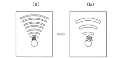
図2は、本件発明者が知見したプロセスの概略を示す図である。当該プロセスでは、まず図2(a)に示すように、高周波数(短波長)の超音波を利用して、対象物(図2の場合、球形物)の近傍の局所的領域に気泡もしくは気泡群を発生させ成長させる。続いて図2(b)に示すように、低周波数(長波長)の超音波を利用して、対象物の近傍に発生及び成長させられていた気泡もしくは気泡群を共振させ崩壊させ、当該崩壊に伴って発散されるエネルギを対象物に付与して、例えば当該対象物を破砕する。
【0056】
図3は、実際に製造された超音波照射装置を示す概略ブロック図である。図3に示す超音波照射装置1は、超音波発生源10と、解析システム20と、循環システム30と、カメラシステム40と、を備えている。
【0057】
超音波発生源10は、ファンクションジェネレータ11と、超音波用アンプ12と、ピエゾトランスデューサ13と、を有している。ファンクションジェネレータ11は、解析システム20のPC(パーソナルコンピュータ)21に接続されており、PC21によって編集される波形を出力するようになっている。
【0058】
より具体的には、PC21にて使用される波形編集ソフトは、Agilent BenchLink Arb である。当該ソフトを用いれば、正弦波、方形波、三角波、それらの波形同士の和、差、積をとった波形の作成が可能である。一方、ファンクションジェネレータ11は、Agilent 社の任意波形ジェネレータ33120Aである。
【0059】
図4は、ピエゾトランスデューサ13の外観を示す図である。図4に示すピエゾトランスデューサ13は、凹面圧電素子として富士セラミクス製のC−213材(PZT)を使用しており、曲率半径は80mm、開口半径は40mm(Fnumber=1.0)であり、固有振動数は500kHzである。凹面圧電素子の電極は銀電極で、当該電極が超音波用アンプ12を介してファンクションジェネレータ11に接続されている。
【0060】
このような凹面圧電素子が、アルミ製の中空フランジに接着されて、ピエゾトランスデューサ13が構成されている。ピエゾトランスデューサ13全体での共振周波数は534kHzである。したがって、ピエゾ素子の特性上、534kHz×(2n+1)(nは整数)の周波数を有する超音波を、高次のモードとして比較的大きな振幅をもってして発生させることができる。使用したピエゾトランスデューサの(2n+1)倍のモードにあたる周波数は、ピエゾトランスデューサからの出力を実測することによって、3倍のモードの周波数は1.632MHz、5倍のモードの周波数は2.726MHz、7倍のモードの周波数は3.815MHz、が得られている。
【0061】
ピエゾトランスデューサ13から照射される超音波は、アクリル製の水槽31に張られた水中を伝わり、凹面圧電素子の表面から80mmの焦点位置にて収束する。アクリル製の水槽は、200mm×200mm×550mmの直方体の後方を45度の角度で切り取った形状をしており、超音波が壁面において反射して焦点付近の音場を乱すことを防いでいる。
【0062】
アクリル水中に張られた水は、図3に示すように、純水装置32、デガッサ33の順に循環されて、好適な純水度、脱気度を維持している。脱気度は、DOメータ36(堀場製作所製OM−10)にて監視される。
【0063】
カメラシステム40は、最小5nsの露光時間、5nsのインターフレームで撮影が可能な超高速カメラ41を有している。
【0064】
図3の超音波照射装置の他の特徴については、本件発明者の一人である吉澤晋氏の修士論文「収束超音波の医療応用」の第7章に詳細に記載されているので、当該文献を引用することによって、ここでの記載を省略する。なお、当該修士論文「収束超音波の医療応用」の内容は、ここでの引用によって本願明細書の記載の一部に組み入れられる。
【0065】
さて、図3に示す超音波照射装置を用いて、モデル結石としての球状対象物(水槽31内の超音波の焦点位置近傍にセットされる)に対して534kHzの超音波を照射した場合の気泡の形成状態について、超高速カメラ41で撮像された画像群を図5に示す。
【0066】
図5に示すように、534kHzの超音波が照射され続ける場合、大型の気泡が群を成して球状対象物の手前側の比較的広範囲に亘って形成される。球状対象物から遠い領域で成長して崩壊する気泡群のエネルギは、球状対象物に十分に伝達されないため、エネルギ的な損失となる。特に、生体内の結石破砕を目的としている場合には、結石から離れた場所での気泡の崩壊は、結石とは無関係の生体内の組織もしくは細胞を損傷させることにつながる。
【0067】
一方、モデル結石としての球状対象物に対してピエゾトランスデューサの7倍のモードである3.815MHzの超音波を照射した場合の気泡の形成状態について、超高速カメラ41で撮像された画像群を図6に示す。
【0068】
図6に示すように、3.815MHzの超音波が照射され続ける場合、細かい気泡からなる気泡群が球状対象物の手前側の比較的狭い範囲にのみ形成される。この場合、対象物の周縁から手前側1mmまでの領域にのみ、気泡群が形成される。このような気泡群は、3.815MHzの超音波の照射が継続されても、崩壊することが無い。従って、当然に、球状対象物にエネルギは伝達されない。
【0069】
次に、本発明方法の一実施の形態に従って、モデル結石としての球状対象物に対してピエゾトランスデューサの7倍の振動モードである3.815kHzの超音波を175波照射した後に、545kHzの超音波(545kHzの超音波は3.815MHzの7分の1である。実際のピエゾトランスデューサの共振周波数は534kHzであるが、実験の簡便のために545kHzを使用している。また、534kHzの周波数及び545kHzの周波数で得られる焦点における超音波の圧力振幅はほぼ等しいことを確認している。)を照射した場合の気泡群の形成状態について、超高速カメラ41で撮像された画像群を図7に示す。5コマ目と6コマ目との間で、超音波周波数は3.815MHzから545kHzに切り替わっている。
【0070】
図7に示すように、本実施の形態の場合、細かい気泡からなる気泡群が球状対象物の手前側の比較的狭い範囲にのみ発生及び成長させられた後、当該気泡群が共振して崩壊し、球状対象物に十分に高エネルギを付与することができる。
【0071】
ここで、本件発明者は、高周波数の超音波の照射と低周波数の超音波の照射とを繰り返し実施することが、対象物に対するエネルギ付与を連続的に行うために好適であることを知見した。
【0072】
高周波数の超音波の照射と低周波数の超音波の照射とを繰り返し実施する場合の2つの具体的態様を、図8及び図9に示す。
【0073】
図8に示す場合、3.815MHzの正弦波形175波の照射の後(第1工程)、約50μ秒のインターバルを設け、その後に545kHzの正弦波形5波の照射を行う(第2工程)という制御サイクルである(第2工程の後には、約100m秒のインターバルが存在する(バースト周波数が10Hz))。
【0074】
図9に示す場合、3.815MHzの正弦波形175波の照射の後、連続して545kHzの正弦波形5波の照射を行い、その後に約100m秒のインターバルが設けられた制御サイクルである。
【0075】
図8及び図9の各制御サイクルに従って、モデル結石の破砕実験を行った。ここで用いたモデル結石とは、アルミナからなるESWL機器の性能試験に用いられるモデル結石であり、φ13mm程度である。
【0076】
なお、図8及び図9のいずれの場合も、バースト周波数は10Hz(すなわちインターバル工程の時間が約100m秒)である。また、図8及び図9のいずれの場合も、各制御サイクルが30分間連続して繰り返された。
【0077】
図8の制御サイクルが利用された場合の破砕結果が、図10に示されている。一方、図9の制御サイクルが利用された場合の破砕結果が、図11に示されている。
【0078】
図10に示すように、第1工程と第2工程との間に50μ秒という長いインターバルが設けられる場合、第1工程で生成された気泡もしくは気泡群が消散してしまって、本発明の意図する効果が十分に得られない。
【0079】
一方、図11に示すように、第1工程と第2工程とが連続に実施され、第2工程の後にインターバルが設けられる場合、第1工程で発生及び成長させられた気泡もしくは気泡群が第2工程にて共振し崩壊して極めて効率的にモデル結石を破砕する一方、第2工程後の100m秒のインターバル工程において気泡もしくは気泡群が沈静化されるため、結石モデルの局所的な破壊を継続することができる。
【0080】
なお、3.815MHzの正弦波形175波の照射の後に約100m秒のインターバル工程が設けられた制御サイクルを用いた場合(第2工程が実施されない制御サイクルの場合)、モデル結石は全く破砕されなかった。
【0081】
また、本件発明者による他の実験結果から、第2工程後に気泡を沈静化させるために必要なインターバル時間は、100μ秒以上が好ましいことが知見された。
【0082】
また、超音波による圧力の強度が比較的小さい場合に、気泡の発生及び成長が誘発されないことを説明するグラフを図12に示す。これは3MHzの超音波がピエゾトランスデューサから30波発生させられたときの水中における焦点の、超音波による圧力振幅(マイナスピークからプラスピークまでの値)をハイドロフォン50によって測定したものである。図12のグラフの横軸は、気泡もしくは気泡群が発生しておらずさらには超音波の波形が歪まない領域での同じ条件における圧力振幅であり、超音波の出力に比例している。縦軸は、ピエゾトランスデューサ13の幾何学焦点におけるハイドロフォン50によって測定された圧力振幅である。図12において超音波出力(横軸に対応)を大きくしてゆくと、焦点における超音波の圧力振幅の値(縦軸に対応)が、約6.8MPaを閾値としてグラフが直線から外れ、焦点における圧力振幅は約7MPaで飽和してしまっている。これは、キャビテーション現象によって気泡もしくは気泡群が発生し、圧力振幅がそれ以上上昇し得ないことを示している。すなわち、この圧力振幅の閾値(今の場合約7MHz)を超えない超音波であれば、気泡もしくは気泡群は発生しない。
【0083】
また、図13は、約3MHzの周波数をもつ比較的弱い圧力振幅をもつ超音波がピエゾトランスデューサから発生させられたときの焦点付近の様子を、高速度カメラ41で撮影した写真である。写真中の濃淡の線は3MHzの超音波によるものである。これによれば、このとき適用された比較的弱い圧力振幅の超音波であれば、気泡もしくは気泡群は発生していないことがわかる。すなわち、比較的弱い圧力振幅をもつ超音波を第2工程後に対象物に対して照射することによって、超音波により発生する音響流を用いることができ、結石の周囲に残る気泡もしくは気泡群の消散を促進させることができ得る。さらには、前記第2工程で破砕された結石の破砕片を結石の周辺から流し去る効果を促進することができ得る。
【0084】
以上の実施の形態は、結石を破砕することについて説明されたが、本発明方法は、対象物が人間以外の動物の生体内に存在する結石等のカルシウム化合物、燐酸マグネシウム化合物、燐酸アンモニウム化合物、尿酸の結晶、アミノ酸の結晶、コレステロールの結晶のいずれか、である場合に適用可能であり、第2工程は、当該対象物に局所的に高エネルギを付与して当該対象物を破砕する工程であり得る。
【0085】
この場合、当該方法を実現するための装置は、設定される周波数情報に基づいて、当該周波数情報に対応する周波数の超音波を発生する超音波発生源(例えばファンクションジェネレータ11)と、超音波発生源に周波数情報を設定するための周波数制御部(例えばPC21)と、を備える。そして、周波数制御部は、第1の所定時間において高周波数が継続し、それに続く第2の所定時間において低周波数が継続する、という周波数情報を超音波発生源に設定するようになっており、第1の所定時間に亘る高周波数の超音波の照射によって、人間以外の動物の生体内に存在するカルシウム化合物、燐酸マグネシウム化合物、燐酸アンモニウム化合物、尿酸の結晶、アミノ酸の結晶、コレステロールの結晶のいずれかの周囲の限定的な領域中に気泡もしくは気泡群を発生及び成長させ、第2の所定時間に亘る低周波数の超音波の照射によって、当該対象物の周囲に発生されていた気泡もしくは気泡群を共振させ崩壊させることによって当該対象物のいずれか、に局所的に高エネルギを付与して当該対象物を破砕することを特徴とする。このような装置は、対象物が人間の生体内に存在する結石等のカルシウム化合物、燐酸マグネシウム化合物、燐酸アンモニウム化合物、尿酸の結晶、アミノ酸の結晶、コレステロールの結晶のいずれかである場合にも利用可能である。
【0086】
あるいは、本発明方法は、異物が付着している対象物に適用可能であり、第2工程は、当該対象物に局所的に高エネルギを付与して当該対象物から異物を剥離もしくは除去する工程であり得る。
【0087】
この場合、当該方法を実現するための装置は、異物が付着した対象物が投入され得る液体収容室と、設定される周波数情報に基づいて、当該周波数情報に対応する周波数の超音波を液体収容室の内部に向けて発生する超音波発生源(例えばファンクションジェネレータ11)と、超音波発生源に周波数情報を設定するための周波数制御部(例えばPC21)と、を備える。そして、周波数制御部は、第1の所定時間において高周波数が継続し、それに続く第2の所定時間において低周波数が継続する、という周波数情報を超音波発生源に設定するようになっており、第1の所定時間に亘る高周波数の超音波の照射によって、異物が付着した対象物の周囲の液体の限定的な領域中に気泡もしくは気泡群を発生及び成長させ、第2の所定時間に亘る低周波数の超音波の照射によって、当該対象物の周囲に発生及び成長させられていた気泡もしくは気泡群を共振させ崩壊させることによって当該対象物に局所的に高エネルギを付与して当該対象物から異物を剥離もしくは除去することを特徴とする。
【0088】
これによれば、いわゆる超音波洗浄処理が、極めて高効率に実現され得る。
【0089】
あるいは、第2工程は、対象物に局所的に高エネルギを付与して当該対象物の特性を変化させる工程であり得る。
【0090】
この場合、当該方法を実現するための装置は、内部に対象物が固定され得る液体収容室と、設定される周波数情報に基づいて、当該周波数情報に対応する周波数の超音波を液体収容室の内部に向けて発生する超音波発生源(例えばファンクションジェネレータ11)と、超音波発生源に周波数情報を設定するための周波数制御部(例えばPC21)と、を備える。そして、周波数制御部は、第1の所定時間において高周波数が継続し、それに続く第2の所定時間において低周波数が継続する、という周波数情報を超音波発生源に設定するようになっており、第1の所定時間に亘る高周波数の超音波の照射によって、対象物の周囲の液体の限定的な領域中に気泡もしくは気泡群を発生及び成長させ、第2の所定時間に亘る低周波数の超音波の照射によって、当該対象物の周囲に発生及び成長させられていた気泡もしくは気泡群を共振させ崩壊させることによって当該対象物に局所的に高エネルギを付与して当該対象物の特性を変化させることを特徴とする。
【0091】
これによれば、いわゆるキャビテーションピーニング処理が、極めて高効率に実現され得る。
【0092】
あるいは、第2工程は、対象物に局所的に高エネルギを付与して生体内の組織もしくは細胞に熱的変性を起こさせる工程であり得る。
【0093】
この場合、当該方法を実現するための装置は、設定される周波数情報に基づいて、当該周波数情報に対応する周波数の超音波を発生する超音波発生源(例えばファンクションジェネレータ11)と、超音波発生源に周波数情報を設定するための周波数制御部(例えばPC21)と、を備える。そして、周波数制御部は、第1の所定時間において高周波数が継続し、それに続く第2の所定時間において低周波数が継続する、という周波数情報を超音波発生源に設定するようになっており、第1の所定時間に亘る高周波数の超音波の照射によって、生体内に存在する組織もしくは細胞の限定的な領域中に気泡もしくは気泡群を発生及び成長させ、第2の所定時間に亘る低周波数の超音波の照射によって、生体内に存在する組織もしくは細胞の限定的な領域中に発生及び成長させられていた気泡もしくは気泡群を共振させ崩壊させることによって当該対象物に局所的に高エネルギを付与して当該対象物に熱的変性を起こさせることを特徴としている。
【0094】
これによれば、いわゆる温熱凝固療法もしくは加熱凝固療法が、極めて高効率に実現され得る。
【図面の簡単な説明】
【図1】クラウド状に形成された気泡群についての周囲圧力波に対する気泡内最大圧力の周波数応答のシミュレーション結果を示すグラフである。
【図2】本発明方法の一実施の形態を示す概略図である。
【図3】本発明装置の一実施の形態を示す概略ブロック図である。
【図4】ピエゾトランスデューサの外観を示す図である。
【図5】534kHzの低周波数の超音波を照射し続けた場合の気泡群の形成状態を示す画像群である。
【図6】3.815MHzの高周波数の超音波を照射し続けた場合の気泡群の形成状態を示す画像群である。
【図7】545kHzの低周波数の超音波を照射した後に、3.815MHzの高低超音波を照射した場合の気泡群の形成状態を示す画像群である。
【図8】高超音波の超音波の照射と低周波数の超音波の照射との間にインターバルが設けられた場合の制御サイクルについて説明する図である。
【図9】高超音波の超音波の照射及び低周波数の超音波の照射の後にインターバルが設けられた場合の制御サイクルについて説明する図である。
【図10】図8による制御サイクルが適用されて破砕された結石モデルを示す概略図である。
【図11】図9による制御サイクルが適用されて破砕された結石モデルを示す概略図である。
【図12】比較的弱い超音波によって気泡もしくは気泡群が発生しないことを説明するグラフである。
【図13】比較的弱い超音波によって気泡もしくは気泡群が発生しないこと示す高速度カメラ写真である。
【図14】周波数変調された駆動信号の時間波形及び周波数の経時的な変化の従来例を示す図である。
【図15】周波数変調された駆動信号の時間波形及び周波数の経時的な変化の従来例を示す図である。
【図16】周波数変調された駆動信号の時間波形及び周波数の経時的な変化の従来例を示す図である。
【図17】周波数変調された駆動信号の時間波形及び周波数の経時的な変化の従来例を示す図である。
【符号の説明】
1 超音波製造装置
10 超音波発生源
11 ファンクションジェネレータ
12 超音波用アンプ
13 ピエゾトランスデューサ13
20 解析システム
21 パーソナルコンピュータ(PC)
30 循環システム
31 水槽
32 純水装置
33 デガッサ
40 カメラシステム
41 超高速カメラ
50 ハイドロフォン[0001]
BACKGROUND OF THE INVENTION
The present invention relates to a method of irradiating an ultrasonic wave toward an object having a liquid in at least a part of the periphery. The present invention also relates to an ultrasonic irradiation apparatus capable of irradiating an object with ultrasonic waves having a frequency based on set frequency information.
[0002]
[Prior art]
In recent years, it has been desired to improve the quality of life (QOL) of patients after surgery. In such a flow, minimally invasive treatment (MIT) has attracted attention. In particular, since 1980s, the study of stone crushing devices by extracorporal shock wave lithotripsy (ESWL), which non-invasively crushes stones by irradiating the stones with shock waves formed by strong ultrasonic waves from outside the body, has been conducted. Has been put to practical use in the medical field. Kidney stones, urinary tract stones, and gallstones are considered to be one of the modern diseases caused by animal protein intake, given that there are few patients in vegetarians and developing countries and many patients in developed countries. The types of stones include calcium oxalate dihydrate or monohydrate stones, calcium phosphate stones, infected stones, uric acid stones, or cystine stones. Examples of gallstones include cholesterol gallstones and pigment gallstones (calcium compounds). Of these, stones made of calcium compounds account for about 90% of all stones, and crushing these calcium compounds is a major goal of stone crushing devices. In addition, cystine stones and gallstones, which are considered to be the hardest stones, can be cited as those that are not easily crushed.
[0003]
Japanese Patent Laid-Open No. 8-131454 discloses that frequency modulation is effective for ultrasonic waves in a therapeutic ultrasonic device.
[0004]
First, frequency modulation disclosed in JP-A-8-131454 will be specifically described below.
[0005]
Driving the piezo element at a resonance frequency f0 specific to the thickness of the piezo element and generating therapeutic ultrasonic waves at the resonance frequency f0 is most preferable from the viewpoint of the conversion efficiency of electrical signals / mechanical vibrations. However, when the therapeutic ultrasonic wave is continuously irradiated for a relatively long period with the resonance frequency f0 being fixed, cavitation (bubbles) gradually grows to a size depending on the wavelength.
[0006]
Therefore, it is proposed to change the frequency fm of the drive signal with time in the range of f0−Δf / 2 ≦ fm ≦ f0 + Δf / 2 with the resonance frequency f0 as the center. Note that the frequency of the drive signal is equivalent to the frequency of the therapeutic ultrasonic wave generated from the ultrasonic wave generation source, and the “drive signal” and the “therapeutic ultrasonic wave” can be interchanged.
[0007]
FIGS. 14 (a), 15 (a), 16 (a), and 17 (a) show time waveforms of various types of drive signals, and FIG. 14 (b), FIG. 15 (b), and FIG. 16 (b) and FIG. 17 (b) show the frequencies (time changes) of the corresponding drive signals.
[0008]
The drive signal in FIG. 14A is generated so that its frequency changes sinusoidally. The drive signal in FIG. 15A is generated such that its frequency changes stepwise. The drive signal in FIG. 16A is generated such that its frequency continuously changes with a constant gradient from a low frequency (f0−Δf / 2) to a high frequency (f0 + Δf / 2). The drive signal in FIG. 17A is generated such that a period in which the frequency is fixed to the resonance frequency f0 and a period in which the frequency changes sinusoidally occur alternately.
[0009]
The change over time of the frequency disclosed in JP-A-8-131454 suppresses the growth of cavitation, disrupts the grown cavitation, and reduces the cavitation of the growth process. It is intended to wipe out adverse effects.
[0010]
[Problems to be solved by the invention]
The effect of cavitation generated by ultrasonic waves is that the tissue or cells in the living body are damaged by the large pressure generated from the cavitation bubbles. Second, the generated cavitation bubbles scatter the ultrasonic waves. It becomes an obstacle when the ultrasonic energy is propagated to the region, and thirdly, a temperature rise at an undesired portion around the cavitation bubble may occur.
[0011]
ESWL devices currently in practical use converge high-pressure shock waves (including high-intensity ultrasonic waves) over a wide area in the body, so that the cavitation phenomenon occurs in a wide area in the body, Tissue or cell damage is occurring. On the other hand, the generation of high pressure due to the collapse of cavitation bubbles or cavitation bubbles can be used to crush the calculus itself, but for that purpose, cavitation bubbles or cavitation bubbles are generated only in the vicinity of the calculus. Therefore, a technology to collapse this is necessary.
[0012]
Furthermore, in the ESWL device currently in practical use, since the fragmented pieces are large, there is a problem that the patient is painful when discharged through the urethra after treatment. That is, there is a demand for a technique for making the crushed pieces as fine as possible.
[0013]
The invention described in Japanese Patent Application Laid-Open No. 8-131454 is mainly directed to attenuating cavitation during the growth process. By removing cavitation from the ultrasonic wave propagation site, it is intended to effectively focus the ultrasonic wave only on the target region and avoid the above three problems. As a result, it is possible to obtain an efficient temperature rise in the target region where the ultrasonic waves are converged.
[0014]
However, when ultrasonic waves are used for crushing stones, the cavitation bubbles or groups of cavitation bubbles that have grown collapse to crush stones (here, collapse of bubbles or groups of bubbles refers to bubbles or groups of bubbles). However, when implosion occurs due to fluctuations in the surrounding pressure, high energy is concentrated near the center of the bubble or bubble group, and a shock wave with a very large pressure is generated. It does not refer to the process of disappearing). That is, the technique described in JP-A-8-131454 is intended to dissipate air bubbles or air bubbles, and is an idea that is contrary to efficient crushing of stones. The technology cannot be used for efficient stone crushing.
[0015]
Furthermore, in the invention described in Japanese Patent Application Laid-Open No. 8-131454, consideration is not sufficiently given to the generation region of cavitation bubbles or cavitation bubble groups. Since cavitation is generated and grown for the purpose of stone crushing, it is sufficient to generate and grow only in the vicinity of the stone. On the other hand, the occurrence and growth of cavitation at a position away from the calculus increases the risk of destroying or damaging undesired in vivo tissues or cells.
[0016]
That is, according to the intention of the invention described in JP-A-8-131454, cavitation bubbles or groups of cavitation bubbles collapse, although destruction or damage of tissues or cells in the living body due to cavitation is avoided. The high energy that sometimes concentrates cannot be used efficiently. In order to efficiently use the high energy at the time of collapse of cavitation bubbles or cavitation bubbles, only the treatment site can be used without using the technique for declining cavitation as in the invention described in JP-A-8-131454. A technique is required that locally generates and grows cavitation bubbles or cavitation bubbles, and effectively causes collapse of the cavitation bubbles and cavitation bubbles only at the site.
[0017]
This invention is made | formed in view of such a situation, and gives a high energy locally to the said target object by irradiating the ultrasonic wave toward the target object in which the liquid exists in at least one part of the circumference | surroundings. It is an object to provide a method or apparatus that can. In addition to calculus crushing, the present invention can be used for crushing gallstones that are difficult to crush in existing calculus crushing devices. In addition, the present invention can be used in a wide range of applications.
[0018]
[Means for Solving the Problems]
The present invention is a method of locally applying high energy to an object by irradiating the object with liquid in at least a part of the surroundings, and applying high-frequency ultrasonic waves to the object. Irradiating the target object to generate and grow cavitation bubbles (hereinafter referred to as bubbles) or cavitation bubble groups (hereinafter referred to as bubble groups) in a limited region of the liquid existing at least in part around the target object. After one step and the first step, bubbles generated and grown in a liquid existing in at least a part of the periphery of the object by irradiating the object with low-frequency ultrasonic waves Alternatively, an ultrasonic irradiation method comprising: a second step of locally applying high energy to the object by resonating and collapsing a bubble group.
[0019]
According to the present invention, bubbles or bubbles are generated and grown in a limited region of liquid existing in at least a part of the periphery of the object by irradiating the object with high-frequency ultrasonic waves. After that, by irradiating the object with low-frequency ultrasonic waves, the bubbles or groups of bubbles generated and grown in the liquid present in at least a part of the periphery of the object are caused to resonate and collapse. , High energy can be locally applied to the object. That is, energy can be imparted to the object very efficiently.
[0020]
In summary, the invention described in JP-A-8-131454 was intended to attenuate cavitation, whereas the present invention concentrates cavitation in a spatially very narrow area, The high energy at the time of cavitation collapse is effectively used to realize efficient high energy concentration.
[0021]
Alternatively, the present invention is a method of locally applying high energy to an object by irradiating ultrasonic waves toward the object in which at least a part of the liquid is present, and having a high frequency. A first step of irradiating an ultrasonic wave toward the object; and a second step of irradiating an ultrasonic wave of a low frequency toward the object after the first step, and irradiating in the first step. The frequency of the ultrasonic wave is 100 kHz or more, and the frequency of the ultrasonic wave irradiated in the second step is one half or less of the frequency of the high-frequency ultrasonic wave irradiated in the first step. This is an ultrasonic irradiation method.
[0022]
According to the present invention, by irradiating an ultrasonic wave with a high frequency of 100 kHz or more toward an object, bubbles or a group of bubbles are formed in a limited region of the liquid existing in at least a part of the periphery of the object. Can be generated and grown. Then, by irradiating the object with a low-frequency ultrasonic wave that is less than half of the frequency of the high-frequency ultrasonic wave, the liquid is present in at least a part of the periphery of the object. In addition, the bubble or the bubble group that has been grown can resonate and collapse. Thereby, high energy can be locally given to the target object.
[0023]
Preferably, the frequency of the high frequency ultrasonic wave in the first step is 1 MHz or more and 10 MHz or less, and the frequency of the low frequency ultrasonic wave in the second step is the high frequency ultrasonic wave irradiated in the first step. Is less than half of the frequency.
[0024]
In this case, by irradiating the object with a high frequency ultrasonic wave of 1 MHz or more and 10 MHz or less, bubbles or bubbles in a limited region of the liquid present in at least a part of the periphery of the object Can be generated and grown. Then, by irradiating the object with a low-frequency ultrasonic wave that is less than half of the frequency of the high-frequency ultrasonic wave, the liquid is present in at least a part of the periphery of the object. In addition, the bubble or the bubble group that has been grown can resonate and collapse. Thereby, high energy can be locally given to the target object. The wavelength of the ultrasonic wave becomes shorter as the frequency becomes higher, and the focal region formed by the ultrasonic wave becomes narrower accordingly. That is, by increasing the frequency of high-frequency ultrasonic waves that generate and grow bubbles or bubbles, the region where bubbles or bubbles are generated in the liquid present in at least a part of the periphery of the object, Further narrowing can be achieved. Thereby, the area | region which provides a high energy locally with respect to the said target object can be further narrowed.
[0025]
Preferably, the second step is performed substantially continuously after the first step.
[0026]
The ultrasonic irradiation is preferably performed in such a manner that the ultrasonic waves converge near the object. For example, a concave piezoelectric element can be used as a source for generating convergent ultrasonic waves.
[0027]
Preferably, the region where bubbles or bubble groups are generated in the first step is a region whose distance from the periphery of the object is 1 mm or less. When bubbles or a group of bubbles are locally formed in a region near such an object, energy can be applied to the object even more efficiently.
[0028]
Preferably, the method further includes an interval step that does not irradiate the object with the ultrasonic wave after the second step. An interval process is a calming process for once dissipating the bubble or the bubble group which resonated and collapsed in the 2nd process. In the interval step, ultrasonic waves having such intensity that does not induce generation and growth of bubbles may be irradiated. By using the acoustic flow generated by this, it is possible to promote the dissipation of bubbles or bubbles existing around the object. Furthermore, it is possible to promote the effect that the fragments of the object or the foreign matter removed from the object is washed away from the periphery of the object.
[0029]
Preferably, the duration of the interval step is a time sufficient for the remaining bubbles to dissolve and diffuse after the second step. For example, the duration of the interval process is 100 μs or more.
[0030]
Preferably, the first step, the second step, and the interval step are repeated periodically in this order. Thereby, in the local region in the vicinity of the object, the cycle of bubble generation, growth, resonance, collapse and dissipation (sedation) is repeated, and high-efficiency energy application to the object is repeated.
[0031]
The duration of the first process and the second process is, for example, about 100 μsec. This is a time corresponding to about 100 waves of 1 MHz ultrasonic waves. The duration of the first step and the second step may be determined by detecting an actual bubble formation state or the like. The bubble formation state can be detected from the state of the generated sound, for example.
[0032]
Specifically, when the target is any one of a calcium compound, a magnesium phosphate compound, an ammonium phosphate compound, a uric acid crystal, an amino acid crystal, and a cholesterol crystal present in the living body of an animal other than a human, the second step May be a step of locally applying high energy to the object to crush the object.
[0033]
Or when the foreign material has adhered to the target object, a 2nd process can be the process of giving a high energy locally to the target object, and peeling or removing the foreign substance from the target object.
[0034]
Or a 2nd process may be a process of giving the high energy locally to the target object, and changing the characteristic of the target object.
[0035]
Alternatively, the second step can be a step in which high energy is locally applied to the living body of an animal other than a human and the tissue or cells in the living body are thermally denatured.
[0036]
In addition, the present invention provides an ultrasonic generation source that generates an ultrasonic wave having a frequency corresponding to the frequency information based on the set frequency information, and a frequency control unit that sets frequency information in the ultrasonic generation source. In the first-stage frequency control, the frequency information that the high frequency continues for the first predetermined time and the low frequency continues for the second predetermined time is set in the ultrasonic wave generation source. The high frequency in the first predetermined time is 100 kHz or more, and the low frequency in the second predetermined time is less than half of the high frequency in the first predetermined time. Device.
[0037]
According to the present invention, by irradiating an ultrasonic wave with a high frequency of 100 kHz or more toward an object, bubbles or a group of bubbles are formed in a limited region of the liquid existing in at least a part of the periphery of the object. Can be generated and grown. Then, by irradiating the object with a low-frequency ultrasonic wave that is less than half of the frequency of the high-frequency ultrasonic wave, the liquid is present in at least a part of the periphery of the object. In addition, the bubble or the bubble group that has been grown can resonate and collapse. Thereby, high energy can be locally given to the target object. That is, energy can be imparted to the object very efficiently.
[0038]
Preferably, the high frequency in the first predetermined time is 1 MHz or more and 10 MHz or less, and the low frequency in the second predetermined time is a half of the frequency of the high frequency ultrasonic wave in the first predetermined time. 1 or less.
[0039]
In this case, by irradiating the object with a high frequency ultrasonic wave of 1 MHz or more and 10 MHz or less, bubbles or bubbles in a limited region of the liquid present in at least a part of the periphery of the object Can be generated and grown. Then, by irradiating the object with a low-frequency ultrasonic wave that is less than half of the frequency of the high-frequency ultrasonic wave, the liquid is present in at least a part of the periphery of the object. In addition, the bubble or the bubble group that has been grown can resonate and collapse. Thereby, high energy can be locally given to the target object. The wavelength of the ultrasonic wave becomes shorter as the frequency becomes higher, and the focal region formed by the ultrasonic wave becomes narrower accordingly. That is, by increasing the frequency of high-frequency ultrasonic waves that generate and grow bubbles or bubbles, the region where bubbles or bubbles are generated in the liquid present in at least a part of the periphery of the object, Further narrowing can be achieved. Thereby, the area | region which provides a high energy locally with respect to the said target object can be further narrowed.
[0040]
Alternatively, the present invention provides an ultrasonic generation source that generates an ultrasonic wave having a frequency corresponding to the frequency information based on the set frequency information, and a frequency control unit for setting the frequency information in the ultrasonic generation source. The frequency control unit sets frequency information that the high frequency continues for the first predetermined time and the low frequency continues for the second predetermined time subsequent to the ultrasonic wave generation source. And, for a third predetermined time after the second predetermined time, do not irradiate ultrasonic waves, or irradiate ultrasonic waves with such intensity that does not induce the generation and growth of bubbles or bubble groups. This is an ultrasonic irradiation apparatus characterized by
[0041]
According to the present invention, a limited region of the liquid existing in at least a part of the periphery of the object is irradiated by irradiating the object having the liquid in at least a part of the periphery with high-frequency ultrasonic waves. Bubbles or groups of bubbles can be generated and grown therein. After that, by irradiating the object with low-frequency ultrasonic waves, the bubbles or bubbles generated and grown in the liquid present in at least part of the periphery of the object resonate and collapse. Can be made. Further, by not irradiating the ultrasonic wave for the third predetermined time thereafter, it is possible to temporarily dissipate the resonated or collapsed bubble or bubble group. Or you may irradiate the ultrasonic wave of the intensity | strength which does not induce bubble generation | occurrence | production and growth in the 3rd predetermined time. By using the acoustic flow generated by this, it is possible to promote the dissipation of bubbles or bubbles existing around the object. Furthermore, it is possible to promote the effect that the fragments of the object or the foreign matter removed from the object is washed away from the periphery of the object. Thereby, while high energy can be locally given to the target object, it is possible to prevent an object around the target object from being damaged by the collapse of bubbles or a group of bubbles.
[0042]
Preferably, the third predetermined time is a time sufficient for the remaining bubbles to dissolve and diffuse after the second predetermined time. For example, the third predetermined time is 100 μsec or more.
[0043]
Preferably, the ultrasonic irradiation apparatus includes a first irradiation step of high-frequency ultrasonic waves for a first predetermined time, and a second irradiation step of low-frequency ultrasonic waves for a second predetermined time thereafter. Then, a cycle consisting of an interval step, in which the ultrasonic wave is not irradiated for the third predetermined time, or only the ultrasonic wave with the intensity that does not induce the generation and growth of bubbles, is repeated. It has become. Thereby, in the local region in the vicinity of the object, the generation, growth, resonance, collapse, and dissipation (sedation) of bubbles or bubbles are repeated, and high-efficiency energy application to the object is repeated.
[0044]
Specifically, according to the present invention, based on the set frequency information, an ultrasonic generation source that generates ultrasonic waves having a frequency corresponding to the frequency information, and a frequency for setting frequency information in the ultrasonic generation source A control unit, and the frequency control unit sets frequency information that the high frequency continues for a first predetermined time and the low frequency continues for a second predetermined time subsequent to the ultrasonic wave generation source. By irradiation with high frequency ultrasonic waves for a first predetermined time, calcium compounds, magnesium phosphate compounds, ammonium phosphate compounds, uric acid crystals, amino acid crystals, cholesterol crystals existing in the living body Generate or grow bubbles or bubbles in a limited area around any of them, and irradiate the target with a low frequency ultrasonic wave for a second predetermined time. An ultrasonic irradiation apparatus characterized in that a high-energy is locally applied to the object by crushing and collapsing bubbles or bubbles generated and grown around the object to crush the object. is there.
[0045]
Alternatively, according to the present invention, an ultrasonic wave having a frequency corresponding to the frequency information is generated toward the inside of the liquid storage chamber based on the set frequency information and the liquid storage chamber into which an object to which foreign matter is attached can be input. And a frequency control unit for setting frequency information in the ultrasonic generation source, wherein the frequency control unit continues the high frequency in a first predetermined time, and then follows a second frequency. The frequency information that the low frequency continues for a predetermined time is set in the ultrasonic wave generation source, and the periphery of the target object to which foreign matter has adhered by irradiation of the high frequency ultrasonic wave for the first predetermined time. If bubbles or bubbles are generated and grown in a limited area of the liquid, and bubbles are generated and grown around the object by irradiation with low frequency ultrasonic waves for a second predetermined time. Is an ultrasound irradiation device, characterized in that the peel or remove foreign matter from the object by applying the locally high energy to said object by disrupting resonate bubbles group.
[0046]
Alternatively, the present invention provides a liquid storage chamber in which an object can be fixed, and an ultrasonic wave that generates ultrasonic waves having a frequency corresponding to the frequency information toward the inside of the liquid storage chamber based on the set frequency information. And a frequency control unit for setting frequency information in the ultrasonic wave generation source, wherein the frequency control unit continues a high frequency in a first predetermined time, and then follows a second predetermined time. The frequency information that the low frequency continues is set in the ultrasonic wave generation source, and the high frequency ultrasonic wave irradiation for the first predetermined time limits the liquid around the object. Bubbles or bubble groups are generated and grown in the region, and the bubbles or bubble groups generated and grown around the object are caused to resonate and collapse by irradiation with low-frequency ultrasonic waves for a second predetermined time. An ultrasonic irradiation apparatus characterized by changing the properties of the object by applying the locally high energy to the object by.
[0047]
Alternatively, the present invention provides an ultrasonic generation source that generates an ultrasonic wave having a frequency corresponding to the frequency information based on the set frequency information, and a frequency control unit for setting the frequency information in the ultrasonic generation source. The frequency control unit sets frequency information that the high frequency continues for the first predetermined time and the low frequency continues for the second predetermined time subsequent to the ultrasonic wave generation source. And a bubble or a group of bubbles is generated and grown in a limited region of tissue or cells existing in the living body by irradiation with a high frequency over a first predetermined time, and a low frequency over a second predetermined time. By irradiating ultrasonic waves and resonating and collapsing bubbles or groups of bubbles generated and grown in a limited area of tissue or cells in the living body, The high energy imparted to an ultrasonic irradiation apparatus characterized by causing thermal denaturation to the object.
[0048]
DETAILED DESCRIPTION OF THE INVENTION
Hereinafter, embodiments of the present invention will be described with reference to the drawings.
[0049]
First, FIG. 1 is a simulation result showing the frequency characteristics of the maximum pressure generated in a bubble with respect to a pressure wave applied around the bubble when the bubble is formed in a cloud shape.
[0050]
The simulation assumed a bubble group (bubble cloud) formed in a convergent sound field in which a concave bubble generating actuator vibrates at a vibration frequency of 3 MHz and converges at the focal point. In the focal region, the ultrasonic waves converge, water is torn by a large negative pressure, and bubbles are generated in the liquid due to the cavitation phenomenon. It was assumed that individual bubbles in the generated bubble group grew to a bubble diameter having a resonance frequency of 3 MHz. Specifically, the radius of the bubble cloud is 0.75 mm, the radius of each bubble is 1.0 μm, the void ratio (the volume ratio of the bubbles relative to the volume of the whole fluid) is 0.1%, the initial ambient pressure is 101.3 kPa, The initial temperature is 293K. Moreover, the pressure wave applied to the circumference | surroundings of a bubble was made into the sine wave, and the amplitude was made into three types, 10 kPa, 50 kPa, and 100 kPa.
[0051]
As shown in FIG. 1, when the ambient pressure of the bubble cloud is increased, the maximum pressure in the bubble is rapidly increased, and the frequency band reaching the high pressure is also widened. Specifically, the maximum pressure for a pressure wave of 110 kHz having an amplitude of 100 kPa is 500 MPa.
[0052]
That is, the bubble group does not resonate at a resonance frequency of 110 kHz, which is a resonance frequency as a bubble group, rather than a resonance frequency as a single bubble. On the other hand, it can be seen that the bubble pressure does not increase at all with respect to 3 MHz (resonant frequency of a single bubble) which is the vibration frequency of the bubble generating actuator.
[0053]
That is, it is preferable to use high-frequency ultrasonic waves to locally generate bubbles, but energy is scattered by the generated bubbles even if high-frequency ultrasonic waves are continuously applied. Group resonances and decays do not occur.
[0054]
Based on the result of FIG. 1, the present inventor first generates a group of bubbles locally using high-frequency (100 kHz or higher) ultrasonic waves, and then generates low-frequency (high-frequency two-minute ultrasonic waves). It was found that a process of generating high energy by resonating and collapsing the bubbles using ultrasonic waves of 1 or less of (1) is feasible.
[0055]
FIG. 2 is a diagram showing an outline of the process discovered by the present inventors. In the process, first, as shown in FIG. 2 (a), bubbles or bubbles are generated in a local region near the object (in the case of FIG. 2, a spherical object) by using high frequency (short wavelength) ultrasonic waves. Generate and grow groups. Subsequently, as shown in FIG. 2 (b), by utilizing ultrasonic waves of low frequency (long wavelength), bubbles or bubble groups generated and grown in the vicinity of the object are resonated and collapsed, and the collapse is performed. For example, the target object is crushed by applying energy to the target object.
[0056]
FIG. 3 is a schematic block diagram showing an actually manufactured ultrasonic irradiation apparatus. The ultrasonic irradiation apparatus 1 illustrated in FIG. 3 includes an
[0057]
The ultrasonic
[0058]
More specifically, the waveform editing software used in the
[0059]
FIG. 4 is a diagram showing the appearance of the
[0060]
Such a concave piezoelectric element is bonded to an aluminum hollow flange to constitute a
[0061]
The ultrasonic wave irradiated from the
[0062]
As shown in FIG. 3, the water stretched in the acrylic water is circulated in the order of the
[0063]
The
[0064]
Other features of the ultrasonic irradiation apparatus of FIG. 3 are described in detail in Chapter 7 of the Master's thesis “Medical Application of Convergent Ultrasound” by one of the inventors of the present invention, Kei Yoshizawa. The description here is omitted by quoting. In addition, the content of the master's thesis “medical application of convergent ultrasound” is incorporated herein by reference.
[0065]
Now, using the ultrasonic irradiation apparatus shown in FIG. 3, bubbles when a 534 kHz ultrasonic wave is irradiated to a spherical object (set near the focal point of the ultrasonic wave in the water tank 31) as a model calculus. FIG. 5 shows a group of images captured by the ultrahigh-
[0066]
As shown in FIG. 5, when 534 kHz ultrasonic waves are continuously irradiated, large bubbles form a group over a relatively wide range on the near side of the spherical object. The energy of the bubble group that grows and collapses in a region far from the spherical object is not sufficiently transmitted to the spherical object, resulting in an energy loss. In particular, when aiming at crushing calculus in a living body, the collapse of bubbles at a place away from the calculus leads to damage of tissues or cells in the living body unrelated to the calculus.
[0067]
On the other hand, an image group captured by the ultrahigh-
[0068]
As shown in FIG. 6, when the 3.815 MHz ultrasonic wave is continuously irradiated, a bubble group composed of fine bubbles is formed only in a relatively narrow range on the near side of the spherical object. In this case, a bubble group is formed only in the region from the periphery of the object to the front side 1 mm. Such a bubble group does not collapse even if the irradiation of the ultrasonic wave of 3.815 MHz is continued. Thus, naturally, no energy is transmitted to the spherical object.
[0069]
Next, according to one embodiment of the method of the present invention, 175 kHz ultrasonic waves, which are a vibration mode seven times that of a piezo transducer, are irradiated to a spherical object as a model calculus, after 175 waves are irradiated, 545 kHz ultrasonic waves (The ultrasonic wave of 545 kHz is 1/7 of 3.815 MHz. The actual resonance frequency of the piezoelectric transducer is 534 kHz, but for the sake of convenience of experiment, 545 kHz is used. Also, the frequency of 534 kHz and 545 kHz are used. FIG. 7 shows an image group captured by the ultrahigh-
[0070]
As shown in FIG. 7, in the case of the present embodiment, after the bubble group consisting of fine bubbles is generated and grown only in a relatively narrow range on the near side of the spherical object, the bubble group resonates and collapses. In addition, a sufficiently high energy can be imparted to the spherical object.
[0071]
Here, the present inventor has found that it is preferable to repeatedly perform irradiation of high-frequency ultrasonic waves and irradiation of low-frequency ultrasonic waves in order to continuously apply energy to the object. .
[0072]
FIG. 8 and FIG. 9 show two specific modes in the case of repeatedly performing high frequency ultrasonic irradiation and low frequency ultrasonic irradiation.
[0073]
In the case shown in FIG. 8, after irradiation of 175 waves of a sine waveform of 3.815 MHz (first step), an interval of about 50 μsec is provided, and then irradiation of 5 waves of a sine waveform of 545 kHz is performed (second step). It is a control cycle (after the second step, there is an interval of about 100 msec (burst frequency is 10 Hz)).
[0074]
In the case shown in FIG. 9, the control cycle is such that, after irradiating 175 waves of a sine waveform of 3.815 MHz, irradiating 5 waves of a sine waveform of 545 kHz continuously, and thereafter providing an interval of about 100 milliseconds.
[0075]
According to each control cycle of FIG.8 and FIG.9, the crushing experiment of the model calculus was conducted. The model calculus used here is a model calculus used for a performance test of an ESWL device made of alumina and has a diameter of about 13 mm.
[0076]
8 and 9, the burst frequency is 10 Hz (that is, the interval process time is about 100 milliseconds). Moreover, in any case of FIG.8 and FIG.9, each control cycle was repeated continuously for 30 minutes.
[0077]
The crushing result when the control cycle of FIG. 8 is used is shown in FIG. On the other hand, the crushing result when the control cycle of FIG. 9 is utilized is shown in FIG.
[0078]
As shown in FIG. 10, when a long interval of 50 μs is provided between the first step and the second step, the bubbles or bubble groups generated in the first step are dissipated, and the intent of the present invention The effect to do is not fully obtained.
[0079]
On the other hand, as shown in FIG. 11, when the first step and the second step are continuously performed and an interval is provided after the second step, the bubbles or bubble groups generated and grown in the first step are While resonating and collapsing in two steps to crush the model stone very efficiently, the bubble or group of bubbles is subsided in the 100 ms interval step after the second step, so local destruction of the stone model Can continue.
[0080]
In addition, when a control cycle provided with an interval process of about 100 milliseconds after irradiation of a 175-wave sine wave of 3.815 MHz is used (in the case of a control cycle in which the second process is not performed), the model stone is not crushed at all. It was.
[0081]
In addition, from other experimental results by the present inventor, it was found that the interval time necessary for calming bubbles after the second step is preferably 100 μsec or more.
[0082]
Further, FIG. 12 shows a graph for explaining that generation and growth of bubbles are not induced when the intensity of pressure by ultrasonic waves is relatively small. This is a measurement of the pressure amplitude (value from minus peak to plus peak) of the focal point in water when 30 waves of 3 MHz ultrasonic waves are generated from the piezoelectric transducer by the
[0083]
FIG. 13 is a photograph taken by the high-
[0084]
Although the above embodiment was explained about crushing a calculus, the method of the present invention includes a calcium compound such as a calculus in which an object exists in the living body of an animal other than a human, a magnesium phosphate compound, an ammonium phosphate compound, Applicable when the crystal is a uric acid crystal, an amino acid crystal, or a cholesterol crystal, and the second step is a step of locally applying high energy to the object to crush the object. possible.
[0085]
In this case, an apparatus for realizing the method includes an ultrasonic generation source (for example, the function generator 11) that generates an ultrasonic wave having a frequency corresponding to the frequency information based on the set frequency information, and an ultrasonic generation. A frequency control unit (for example, PC21) for setting frequency information in the source. The frequency control unit is configured to set the frequency information that the high frequency continues in the first predetermined time and the low frequency continues in the second predetermined time subsequent to the ultrasonic wave generation source, Any of calcium compounds, magnesium phosphate compounds, ammonium phosphate compounds, uric acid crystals, amino acid crystals, and cholesterol crystals present in the living body of animals other than humans by irradiation with high-frequency ultrasonic waves for the first predetermined time. The bubble or bubble group generated and grown in a limited area around the object and irradiated with the low frequency ultrasonic wave for the second predetermined time is generated around the object. By resonating and collapsing the object, any one of the objects is locally given high energy to crush the object. Such a device is also used when the target object is any one of calcium compounds such as stones, magnesium phosphate compounds, ammonium phosphate compounds, uric acid crystals, amino acid crystals, and cholesterol crystals that exist in the human body. Is possible.
[0086]
Alternatively, the method of the present invention can be applied to an object to which foreign matter is attached, and the second step is a step of locally applying high energy to the target object to peel or remove the foreign object from the target object. It can be.
[0087]
In this case, the apparatus for realizing the method includes a liquid storage chamber in which an object to which foreign matter is attached can be put, and an ultrasonic wave having a frequency corresponding to the frequency information based on the set frequency information. An ultrasonic generation source (for example, the function generator 11) that is generated toward the inside of the room, and a frequency control unit (for example, PC21) for setting frequency information in the ultrasonic generation source. The frequency control unit is configured to set the frequency information that the high frequency continues in the first predetermined time and the low frequency continues in the second predetermined time subsequent to the ultrasonic wave generation source, Bubbles or bubble groups are generated and grown in a limited area of the liquid around the object to which the foreign matter has adhered by irradiation with high frequency ultrasonic waves over a first predetermined time, and over a second predetermined time. By applying a low frequency ultrasonic wave to resonate and collapse a bubble or a group of bubbles generated and grown around the target object, the target object is locally given high energy, and is then released from the target object. It is characterized by peeling or removing foreign matter.
[0088]
According to this, so-called ultrasonic cleaning treatment can be realized with extremely high efficiency.
[0089]
Or a 2nd process may be a process of giving the high energy locally to a target object, and changing the characteristic of the target object.
[0090]
In this case, an apparatus for realizing the method includes a liquid storage chamber in which an object can be fixed, and ultrasonic waves having a frequency corresponding to the frequency information based on the set frequency information. An ultrasonic generation source (for example, the function generator 11) generated toward the inside, and a frequency control unit (for example, the PC 21) for setting frequency information in the ultrasonic generation source are provided. The frequency control unit is configured to set the frequency information that the high frequency continues in the first predetermined time and the low frequency continues in the second predetermined time subsequent to the ultrasonic wave generation source, By irradiating with a high frequency ultrasonic wave for a first predetermined time, bubbles and bubble groups are generated and grown in a limited area of the liquid around the object, and a low frequency ultrasonic wave for a second predetermined time is generated. By irradiating the sound wave, a bubble or a group of bubbles generated and grown around the object is caused to resonate and collapse, thereby locally applying high energy to the object and changing the characteristics of the object. It is characterized by that.
[0091]
According to this, so-called cavitation peening processing can be realized with extremely high efficiency.
[0092]
Alternatively, the second step may be a step in which high energy is locally applied to the object to cause thermal denaturation of the tissue or cells in the living body.
[0093]
In this case, an apparatus for realizing the method includes an ultrasonic generation source (for example, the function generator 11) that generates an ultrasonic wave having a frequency corresponding to the frequency information based on the set frequency information, and an ultrasonic generation. A frequency control unit (for example, PC21) for setting frequency information in the source. The frequency control unit is configured to set the frequency information that the high frequency continues in the first predetermined time and the low frequency continues in the second predetermined time subsequent to the ultrasonic wave generation source, Bubbles or bubble groups are generated and grown in a limited region of tissue or cells existing in the living body by irradiation with high-frequency ultrasonic waves for a first predetermined time, and a low frequency for a second predetermined time. By irradiating the ultrasonic wave of the target, high energy is locally applied to the target object by resonating and collapsing bubbles or bubble groups generated and grown in a limited region of tissue or cells existing in the living body. It is characterized in that it is imparted to cause thermal denaturation of the object.
[0094]
According to this, so-called thermocoagulation therapy or heat coagulation therapy can be realized with extremely high efficiency.
[Brief description of the drawings]
FIG. 1 is a graph showing a simulation result of a frequency response of a maximum pressure in a bubble with respect to an ambient pressure wave with respect to a group of bubbles formed in a cloud shape.
FIG. 2 is a schematic view showing an embodiment of the method of the present invention.
FIG. 3 is a schematic block diagram showing an embodiment of the device of the present invention.
FIG. 4 is a diagram illustrating an appearance of a piezo transducer.
FIG. 5 is an image group showing a formation state of a bubble group in a case where irradiation with low frequency ultrasonic waves of 534 kHz is continued.
FIG. 6 is a group of images showing a formation state of bubbles when a high frequency ultrasonic wave of 3.815 MHz is continuously irradiated.
FIG. 7 is an image group showing a formation state of a bubble group when a high frequency ultrasonic wave of 3.815 MHz is irradiated after irradiating a low frequency ultrasonic wave of 545 kHz.
FIG. 8 is a diagram for explaining a control cycle in the case where an interval is provided between high-frequency ultrasonic irradiation and low-frequency ultrasonic irradiation.
FIG. 9 is a diagram for explaining a control cycle in the case where an interval is provided after irradiation of high-frequency ultrasonic waves and low-frequency ultrasonic waves.
FIG. 10 is a schematic diagram showing a calculus model crushed by applying the control cycle according to FIG. 8;
FIG. 11 is a schematic diagram showing a calculus model crushed by applying the control cycle according to FIG. 9;
FIG. 12 is a graph for explaining that bubbles or bubble groups are not generated by relatively weak ultrasonic waves.
FIG. 13 is a high-speed camera photograph showing that bubbles or bubble groups are not generated by relatively weak ultrasonic waves.
FIG. 14 is a diagram illustrating a conventional example of a time waveform of a frequency-modulated drive signal and a change with time of the frequency.
FIG. 15 is a diagram illustrating a conventional example of a time waveform of a frequency-modulated drive signal and a change over time in frequency.
FIG. 16 is a diagram illustrating a conventional example of a time waveform of a frequency-modulated drive signal and a change over time in frequency.
FIG. 17 is a diagram illustrating a conventional example of a time waveform of a frequency-modulated drive signal and a change with time of the frequency.
[Explanation of symbols]
1 Ultrasonic production equipment
10 Ultrasonic source
11 Function generator
12 Ultrasonic amplifier
13
20 Analysis system
21 Personal computer (PC)
30 Circulation system
31 Aquarium
32 Pure water equipment
33 Degassa
40 camera system
41 Super high speed camera
50 Hydrophone
Claims (20)
高周波数の超音波を対象物に向けて照射して、当該対象物の周囲の少なくとも一部に存在する液体の限定的な領域中に気泡もしくは気泡群を発生及び成長させる第1工程と、
前記第1工程の後に、低周波数の超音波を対象物に向けて照射して、当該対象物の周囲の少なくとも一部に存在する液体中に発生及び成長させられていた気泡もしくは気泡群を共振させ崩壊させることによって当該対象物に局所的に高エネルギを付与する第2工程と、
前記第2工程の後に、超音波を対象物に向けて照射しない、あるいは、気泡の発生及び成長を誘発しない程度の強度の超音波のみを照射するインターバル工程と、
を備え、
前記第1工程、前記第2工程及び前記インターバル工程が、当該順序で周期的に繰り返し実施される
ことを特徴とする超音波照射方法。A method for locally applying high energy to an object by irradiating an object in a living body of an animal other than a human having a liquid in at least a part of the surroundings,
A first step of irradiating a target with high frequency ultrasonic waves to generate and grow bubbles or groups of bubbles in a limited area of liquid present in at least a portion of the periphery of the target;
After the first step, a low frequency ultrasonic wave is irradiated toward the object to resonate the bubbles or the bubbles that are generated and grown in the liquid present in at least a part of the periphery of the object. A second step of locally imparting high energy to the object by letting it collapse;
After the second step, an interval step of irradiating only the ultrasonic wave with an intensity that does not irradiate ultrasonic waves toward the object or does not induce generation and growth of bubbles, and
Equipped with a,
The ultrasonic irradiation method , wherein the first step, the second step, and the interval step are periodically repeated in this order .
高周波数の超音波を対象物に向けて照射する第1工程と、
前記第1工程の後に、低周波数の超音波を対象物に向けて照射する第2工程と、
前記第2工程の後に、超音波を対象物に向けて照射しない、あるいは、気泡の発生及び成長を誘発しない程度の強度の超音波のみを照射するインターバル工程と、
を備え、
第1工程において照射される超音波の周波数は、100kHz以上であり、
第2工程において照射される超音波の周波数は、第1工程において照射される超音波の周波数の2分の1以下であり、
前記第1工程、前記第2工程及び前記インターバル工程が、当該順序で周期的に繰り返し実施される
ことを特徴とする超音波照射方法。A method for locally applying high energy to an object by irradiating an object in a living body of an animal other than a human having a liquid in at least a part of the surroundings,
A first step of irradiating a target with high frequency ultrasonic waves;
After the first step, a second step of irradiating the object with low frequency ultrasonic waves;
After the second step, an interval step of irradiating only the ultrasonic wave with an intensity that does not irradiate ultrasonic waves toward the object or does not induce generation and growth of bubbles, and
With
The frequency of the ultrasonic wave irradiated in the first step is 100 kHz or more,
Frequency of the ultrasonic wave emitted at the second step state, and are less than half of the frequency of ultrasonic waves to be irradiated in the first step,
The ultrasonic irradiation method , wherein the first step, the second step, and the interval step are periodically repeated in this order .
第2工程において照射される超音波の周波数は、第1工程において照射される超音波の周波数の2分の1以下である
ことを特徴とする請求項2に記載の超音波照射方法。The frequency of the ultrasonic wave irradiated in the first step is 1 MHz or more and 10 MHz or less,
The ultrasonic irradiation method according to claim 2, wherein the frequency of the ultrasonic wave irradiated in the second step is equal to or less than half of the frequency of the ultrasonic wave irradiated in the first step.
ことを特徴とする請求項1乃至3のいずれかに記載の超音波照射方法。The ultrasonic irradiation method according to claim 1, wherein the second step is performed substantially continuously after the first step.
ことを特徴とする請求項1乃至4のいずれかに記載の超音波照射方法。The ultrasonic wave according to any one of claims 1 to 4, wherein a region where bubbles or bubble groups are generated and grows in the first step can be controlled to a region whose distance from the periphery of the object is 1 mm or less. Irradiation method.
ことを特徴とする請求項1乃至5のいずれかに記載の超音波照射方法。The ultrasonic irradiation method according to claim 1, wherein the duration of the interval step is a time sufficient for the remaining bubbles to dissolve and diffuse after the second step.
ことを特徴とする請求項1乃至5のいずれかに記載の超音波照射方法。The ultrasonic irradiation method according to claim 1, wherein the duration of the interval step is 100 μsec or more.
第2工程は当該対象物に局所的に高エネルギを付与して、当該対象物を破砕する工程である
ことを特徴とする請求項1乃至7のいずれかに記載の超音波照射方法。The object is any one of a calcium compound, a magnesium phosphate compound, an ammonium phosphate compound, a uric acid crystal, an amino acid crystal, and a cholesterol crystal present in the living body of an animal other than a human,
The second step is to impart locally high energy to said object, an ultrasonic irradiation method according to any one of claims 1 to 7, characterized in that a step of crushing the object.
第2工程は、当該対象物に局所的に高エネルギを付与して、当該対象物から異物を剥離もしくは除去する工程である
ことを特徴とする請求項1乃至7のいずれかに記載の超音波照射方法。Foreign objects are attached to the object,
The ultrasonic wave according to any one of claims 1 to 7 , wherein the second step is a step of locally applying high energy to the object and peeling or removing the foreign matter from the object. Irradiation method.
ことを特徴とする請求項1乃至7のいずれかに記載の超音波照射方法。The ultrasonic irradiation method according to any one of claims 1 to 7 , wherein the second step is a step of locally applying high energy to the object to change characteristics of the object. .
第2工程は当該対象物に局所的に高エネルギを付与して、当該対象物に熱的変性を起こす
ことを特徴とする請求項1乃至7のいずれかに記載の超音波照射方法。The object is any tissue or cell that exists in the living body of an animal other than a human,
The ultrasonic irradiation method according to any one of claims 1 to 7, wherein in the second step, high energy is locally applied to the object to cause thermal denaturation of the object.
超音波発生源に周波数情報を設定するための周波数制御部と、
を備え、
前記周波数制御部は、第1の所定時間において高周波数が継続し、それに続く第2の所定時間において低周波数が継続する、という周波数情報を超音波発生源に設定するようになっており、
第2の所定時間の後の第3の所定時間の間、対象物に超音波を照射しないことが可能であるか、あるいは、気泡の発生及び成長を誘発しない程度の強度の超音波のみを照射することが可能であり、
第1の所定時間に亘る高周波数の超音波の第1照射工程と、それに続く第2の所定時間に亘る低周波数の超音波の第2照射工程と、それに続く請求項13乃至15のいずれかに記載の第3の所定時間に亘る工程と、からなるサイクルを繰り返し実施するようになっている
ことを特徴とする超音波照射装置。Based on the set frequency information, an ultrasonic wave generation source that generates an ultrasonic wave of a frequency corresponding to the frequency information,
A frequency control unit for setting frequency information in the ultrasonic wave generation source;
With
The frequency control unit is configured to set the frequency information that the high frequency continues in the first predetermined time and the low frequency continues in the second predetermined time subsequent to the ultrasonic wave generation source,
During the third predetermined time after the second predetermined time, it is possible not to irradiate the object with ultrasonic waves, or to irradiate only ultrasonic waves with an intensity that does not induce the generation and growth of bubbles. could der be is,
16. A first irradiation step of high-frequency ultrasonic waves over a first predetermined time, a second irradiation step of low-frequency ultrasonic waves over a second predetermined time, and a subsequent step. An ultrasonic irradiation apparatus characterized in that a cycle comprising a step over a third predetermined time described in the above is repeatedly performed .
ことを特徴とする請求項12に記載の超音波照射装置。The ultrasonic irradiation apparatus according to claim 12 , wherein the third predetermined time is a time sufficient for the remaining bubbles to dissolve and diffuse after the second predetermined time.
ことを特徴とする請求項12に記載の超音波照射装置。The ultrasonic irradiation apparatus according to claim 12 , wherein the third predetermined time is 100 μsec or more.
第2工程において照射される超音波の周波数は、第1工程において照射される超音波の周波数の2分の1以下である
ことを特徴とする請求項12に記載の超音波照射装置。The frequency of the ultrasonic wave irradiated in the first step is 100 kHz or more,
The ultrasonic irradiation apparatus according to claim 12 , wherein the frequency of the ultrasonic wave irradiated in the second step is equal to or less than half of the frequency of the ultrasonic wave irradiated in the first step.
第2工程において照射される超音波の周波数は、第1工程において照射される超音波の周波数の2分の1以下である
ことを特徴とする請求項15に記載の超音波照射装置。The frequency of the ultrasonic wave irradiated in the first step is 1 MHz or more and 10 MHz or less,
The ultrasonic irradiation apparatus according to claim 15 , wherein the frequency of the ultrasonic wave irradiated in the second step is half or less of the frequency of the ultrasonic wave irradiated in the first step.
第2の所定時間に亘る低周波数の超音波の照射によって、当該カルシウム化合物、燐酸マグネシウム化合物、燐酸アンモニウム化合物、尿酸の結晶、アミノ酸の結晶、コレステロールの結晶のいずれかの周囲に発生及び成長させられていた気泡もしくは気泡群を共振させ崩壊させることによって当該カルシウム化合物、燐酸マグネシウム化合物、燐酸アンモニウム化合物、尿酸の結晶、アミノ酸の結晶、コレステロールの結晶のいずれかに局所的に高エネルギを付与して当該カルシウム化合物、燐酸マグネシウム化合物、燐酸アンモニウム化合物、尿酸の結晶、アミノ酸の結晶、コレステロールの結晶のいずれかを破砕する
ことを特徴とする請求項12に記載の超音波照射装置。A limited area around any of the calcium, magnesium phosphate, ammonium phosphate, uric acid, amino acid, and cholesterol crystals present in the living body by high frequency irradiation over a first predetermined time. Generate and grow bubbles or bubbles inside,
It is generated and grown around any of the calcium compound, magnesium phosphate compound, ammonium phosphate compound, uric acid crystal, amino acid crystal and cholesterol crystal by irradiation with low frequency ultrasonic waves for a second predetermined time. By resonating and collapsing the bubbles or groups of bubbles, the calcium compound, magnesium phosphate compound, ammonium phosphate compound, uric acid crystal, amino acid crystal, and cholesterol crystal are locally given high energy to The ultrasonic irradiation apparatus according to claim 12 , wherein any one of a calcium compound, a magnesium phosphate compound, an ammonium phosphate compound, a uric acid crystal, an amino acid crystal, and a cholesterol crystal is crushed.
設定される周波数情報に基づいて、当該周波数情報に対応する周波数の超音波を液体収容室の内部に向けて発生する超音波発生源と、
超音波発生源に周波数情報を設定するための周波数制御部と、
を備え、
前記周波数制御部は、第1の所定時間において高周波数が継続し、それに続く第2の所定時間において低周波数が継続する、という周波数情報を超音波発生源に設定するようになっており、
第2の所定時間の後の第3の所定時間の間、対象物に超音波を照射しないことが可能であるか、あるいは、気泡の発生及び成長を誘発しない程度の強度の超音波のみを照射することが可能であり、
第1の所定時間に亘る高周波数の超音波の照射によって、異物が付着した対象物の周囲に存在する液体の限定的な領域中に気泡もしくは気泡群を発生及び成長させ、
第2の所定時間に亘る低周波数の超音波の照射によって、異物が付着した対象物の周囲に発生及び成長させられていた気泡もしくは気泡群を共振させ崩壊させることによって、当該対象物に局所的に高エネルギを付与して当該対象物から異物を剥離もしくは除去し、
第1の所定時間に亘る高周波数の超音波の第1照射工程と、それに続く第2の所定時間に亘る低周波数の超音波の第2照射工程と、それに続く請求項13乃至15のいずれかに記載の第3の所定時間に亘る工程と、からなるサイクルを繰り返し実施するようになっている
ことを特徴とする超音波照射装置。A liquid storage chamber into which an object to which foreign matter adheres can be placed;
Based on the set frequency information, an ultrasonic generation source that generates an ultrasonic wave having a frequency corresponding to the frequency information toward the inside of the liquid storage chamber,
A frequency control unit for setting frequency information in the ultrasonic wave generation source;
With
The frequency control unit is configured to set the frequency information that the high frequency continues in the first predetermined time and the low frequency continues in the second predetermined time subsequent to the ultrasonic wave generation source,
During the third predetermined time after the second predetermined time, it is possible not to irradiate the object with ultrasonic waves, or to irradiate only ultrasonic waves with an intensity that does not induce the generation and growth of bubbles. Is possible and
By irradiating with a high frequency ultrasonic wave for a first predetermined time, bubbles or bubbles are generated and grown in a limited area of the liquid around the object to which the foreign matter has adhered,
By irradiating the low frequency ultrasonic wave for the second predetermined time, the bubbles or bubbles generated and grown around the object to which the foreign matter has adhered are caused to resonate and collapse, thereby localizing the object. Applying high energy to the object to peel or remove foreign matter ,
16. A first irradiation step of high-frequency ultrasonic waves over a first predetermined time, a second irradiation step of low-frequency ultrasonic waves over a second predetermined time, and a subsequent step. An ultrasonic irradiation apparatus characterized in that a cycle comprising a step over a third predetermined time described in the above is repeatedly performed .
設定される周波数情報に基づいて、当該周波数情報に対応する周波数の超音波を液体収容室の内部に向けて発生する超音波発生源と、
超音波発生源に周波数情報を設定するための周波数制御部と、
を備え、
前記周波数制御部は、第1の所定時間において高周波数が継続し、それに続く第2の所定時間においての低周波数が継続する、という周波数情報を超音波発生源に設定するようになっており、
第2の所定時間の後の第3の所定時間の間、対象物に超音波を照射しないことが可能であるか、あるいは、気泡の発生及び成長を誘発しない程度の強度の超音波のみを照射することが可能であり、
第1の所定時間に亘る低周波数の超音波の照射によって、対象物の周囲の液体の限定的な領域中に気泡もしくは気泡群を発生及び成長させ、
第2の所定時間に亘る低周波数の超音波の照射によって、対象物の周囲に発生及び成長させられていた気泡もしくは気泡群を共振させ崩壊させることによって、当該対象物に局所的に高エネルギを付与して当該対象物の特性を変化させ、
第1の所定時間に亘る高周波数の超音波の第1照射工程と、それに続く第2の所定時間に亘る低周波数の超音波の第2照射工程と、それに続く請求項13乃至15のいずれかに記載の第3の所定時間に亘る工程と、からなるサイクルを繰り返し実施するようになっている
ことを特徴とする超音波照射装置。A liquid storage chamber in which an object can be fixed;
Based on the set frequency information, an ultrasonic generation source that generates an ultrasonic wave having a frequency corresponding to the frequency information toward the inside of the liquid storage chamber,
A frequency control unit for setting frequency information in the ultrasonic wave generation source;
With
The frequency control unit is configured to set the frequency information that the high frequency continues in the first predetermined time and the low frequency continues in the second predetermined time subsequent to the ultrasonic wave generation source,
During the third predetermined time after the second predetermined time, it is possible not to irradiate the object with ultrasonic waves, or to irradiate only ultrasonic waves with an intensity that does not induce the generation and growth of bubbles. Is possible and
Generating and growing bubbles or bubble groups in a limited area of liquid around the object by irradiation with low frequency ultrasound for a first predetermined time;
By irradiating low frequency ultrasonic waves over a second predetermined time, the bubbles or bubble groups generated and grown around the object are resonated and collapsed, whereby high energy is locally applied to the object. imparting to alter the properties of the object,
16. A first irradiation step of high-frequency ultrasonic waves over a first predetermined time, a second irradiation step of low-frequency ultrasonic waves over a second predetermined time, and a subsequent step. An ultrasonic irradiation apparatus characterized in that a cycle comprising a step over a third predetermined time described in the above is repeatedly performed .
第2の所定時間に亘る低周波数の超音波の照射によって、生体内に存在する組織もしくは細胞の限定的な領域に発生及び成長させられていた気泡もしくは気泡群を共振させ崩壊させることによって、当該対象物に局所的に高エネルギを付与し当該対象物に熱的変性を起こす
ことを特徴とする請求項12に記載の超音波照射装置。Generating and growing bubbles or bubble groups in a limited area of tissue or cells present in the living body by irradiation at a high frequency for a first predetermined time;
By resonating and collapsing bubbles or bubble groups generated and grown in a limited region of tissue or cells existing in the living body by irradiation with low-frequency ultrasonic waves for the second predetermined time, The ultrasonic irradiation apparatus according to claim 12 , wherein high energy is locally applied to an object to cause thermal denaturation of the object.
Priority Applications (1)
| Application Number | Priority Date | Filing Date | Title |
|---|---|---|---|
| JP2002194791A JP4139916B2 (en) | 2002-07-03 | 2002-07-03 | Ultrasonic irradiation method and ultrasonic irradiation apparatus |
Applications Claiming Priority (1)
| Application Number | Priority Date | Filing Date | Title |
|---|---|---|---|
| JP2002194791A JP4139916B2 (en) | 2002-07-03 | 2002-07-03 | Ultrasonic irradiation method and ultrasonic irradiation apparatus |
Publications (2)
| Publication Number | Publication Date |
|---|---|
| JP2004033476A JP2004033476A (en) | 2004-02-05 |
| JP4139916B2 true JP4139916B2 (en) | 2008-08-27 |
Family
ID=31703399
Family Applications (1)
| Application Number | Title | Priority Date | Filing Date |
|---|---|---|---|
| JP2002194791A Expired - Fee Related JP4139916B2 (en) | 2002-07-03 | 2002-07-03 | Ultrasonic irradiation method and ultrasonic irradiation apparatus |
Country Status (1)
| Country | Link |
|---|---|
| JP (1) | JP4139916B2 (en) |
Families Citing this family (6)
| Publication number | Priority date | Publication date | Assignee | Title |
|---|---|---|---|---|
| JPWO2005094701A1 (en) * | 2004-03-31 | 2008-02-14 | 株式会社東京大学Tlo | Ultrasonic irradiation method and ultrasonic irradiation apparatus |
| CN101980667B (en) * | 2008-04-04 | 2012-08-15 | 株式会社日立制作所 | Ultrasonic wave irradiation device |
| RU2479346C1 (en) * | 2011-08-29 | 2013-04-20 | Андрей Александрович Геталов | Method of simultaneous ultrasound cavitation processing of different-composition media |
| JP5998017B2 (en) * | 2012-11-09 | 2016-09-28 | 株式会社日立製作所 | Ultrasonic therapy apparatus and ultrasonic therapy support system |
| CN105407968B (en) | 2013-07-03 | 2019-09-03 | 博莱科瑞士股份公司 | Equipment for the ultrasound disposition to ishemic stroke |
| CN110300550B (en) * | 2017-02-28 | 2021-12-07 | 奥林巴斯株式会社 | Ultrasonic medical device |
-
2002
- 2002-07-03 JP JP2002194791A patent/JP4139916B2/en not_active Expired - Fee Related
Also Published As
| Publication number | Publication date |
|---|---|
| JP2004033476A (en) | 2004-02-05 |
Similar Documents
| Publication | Publication Date | Title |
|---|---|---|
| US10772646B2 (en) | Method for controlling histotripsy using confocal fundamental and harmonic superposition combined with hundred-microsecond ultrasound pulses | |
| Maxwell et al. | Fragmentation of urinary calculi in vitro by burst wave lithotripsy | |
| Bailey et al. | Physical mechanisms of the therapeutic effect of ultrasound (a review) | |
| Maxwell et al. | Disintegration of tissue using high intensity focused ultrasound: Two approaches that utilize shock waves | |
| US5582578A (en) | Method for the comminution of concretions | |
| US8162858B2 (en) | Ultrasonic medical treatment device with variable focal zone | |
| US5827204A (en) | Medical noninvasive operations using focused modulated high power ultrasound | |
| US10806952B2 (en) | Therapeutic ultrasound apparatus and method | |
| TWI382860B (en) | Noninvasively low-frequency ultrasonic apparatus for the brain therapy and the method thereof | |
| WO2005074365A2 (en) | Localized production of microbubbles and control of cavitational and heating effects by use of enhanced ultrasound | |
| Duryea et al. | Removal of residual cavitation nuclei to enhance histotripsy fractionation of soft tissue | |
| Takagi et al. | Cavitation inception by dual-frequency excitation in high-intensity focused ultrasound treatment | |
| Duryea et al. | Removal of residual nuclei following a cavitation event using low-amplitude ultrasound | |
| JP5775751B2 (en) | Ultrasonic irradiation device | |
| WO2018018725A1 (en) | Two-stage hundred-microsecond pulse focused ultrasound tissue destruction method | |
| JP4139916B2 (en) | Ultrasonic irradiation method and ultrasonic irradiation apparatus | |
| Wang et al. | Suppressing bubble shielding effect in shock wave lithotripsy by low intensity pulsed ultrasound | |
| US11583299B1 (en) | Noninvasive fragmentation of urinary tract stones with focused ultrasound | |
| Azuma et al. | Schlieren observation of therapeutic field in water surrounded by cranium radiated from 500 kHz ultrasonic sector transducer | |
| Alavi Tamaddoni et al. | Enhanced shockwave lithotripsy with active cavitation mitigation | |
| Yang et al. | Medical ultrasonic treatment and its applications in medicine | |
| Nishihara et al. | Heating location control of HIFU treatment enhanced with microbubbles | |
| Abedini et al. | A review of applications of high power ultrasound technology in medical surgery | |
| Duryea et al. | Active removal of residual bubble nuclei following a cavitation event | |
| Li et al. | Development of piezoelectric ultrasonic thrombolysis device for blood clot emulsification |
Legal Events
| Date | Code | Title | Description |
|---|---|---|---|
| A711 | Notification of change in applicant |
Free format text: JAPANESE INTERMEDIATE CODE: A711 Effective date: 20050407 |
|
| A521 | Written amendment |
Free format text: JAPANESE INTERMEDIATE CODE: A821 Effective date: 20050407 |
|
| A621 | Written request for application examination |
Free format text: JAPANESE INTERMEDIATE CODE: A621 Effective date: 20050615 |
|
| A521 | Written amendment |
Free format text: JAPANESE INTERMEDIATE CODE: A523 Effective date: 20050610 |
|
| A711 | Notification of change in applicant |
Free format text: JAPANESE INTERMEDIATE CODE: A711 Effective date: 20050916 |
|
| A521 | Written amendment |
Free format text: JAPANESE INTERMEDIATE CODE: A821 Effective date: 20050916 |
|
| A977 | Report on retrieval |
Free format text: JAPANESE INTERMEDIATE CODE: A971007 Effective date: 20070409 |
|
| A131 | Notification of reasons for refusal |
Free format text: JAPANESE INTERMEDIATE CODE: A131 Effective date: 20070907 |
|
| A521 | Written amendment |
Free format text: JAPANESE INTERMEDIATE CODE: A523 Effective date: 20071030 |
|
| A131 | Notification of reasons for refusal |
Free format text: JAPANESE INTERMEDIATE CODE: A131 Effective date: 20071214 |
|
| A521 | Written amendment |
Free format text: JAPANESE INTERMEDIATE CODE: A523 Effective date: 20080212 |
|
| TRDD | Decision of grant or rejection written | ||
| A01 | Written decision to grant a patent or to grant a registration (utility model) |
Free format text: JAPANESE INTERMEDIATE CODE: A01 Effective date: 20080401 |
|
| A01 | Written decision to grant a patent or to grant a registration (utility model) |
Free format text: JAPANESE INTERMEDIATE CODE: A01 |
|
| A61 | First payment of annual fees (during grant procedure) |
Free format text: JAPANESE INTERMEDIATE CODE: A61 Effective date: 20080522 |
|
| FPAY | Renewal fee payment (event date is renewal date of database) |
Free format text: PAYMENT UNTIL: 20110620 Year of fee payment: 3 |
|
| R150 | Certificate of patent or registration of utility model |
Free format text: JAPANESE INTERMEDIATE CODE: R150 |
|
| S111 | Request for change of ownership or part of ownership |
Free format text: JAPANESE INTERMEDIATE CODE: R313117 |
|
| FPAY | Renewal fee payment (event date is renewal date of database) |
Free format text: PAYMENT UNTIL: 20110620 Year of fee payment: 3 |
|
| R350 | Written notification of registration of transfer |
Free format text: JAPANESE INTERMEDIATE CODE: R350 |
|
| FPAY | Renewal fee payment (event date is renewal date of database) |
Free format text: PAYMENT UNTIL: 20110620 Year of fee payment: 3 |
|
| S111 | Request for change of ownership or part of ownership |
Free format text: JAPANESE INTERMEDIATE CODE: R313113 |
|
| FPAY | Renewal fee payment (event date is renewal date of database) |
Free format text: PAYMENT UNTIL: 20110620 Year of fee payment: 3 |
|
| FPAY | Renewal fee payment (event date is renewal date of database) |
Free format text: PAYMENT UNTIL: 20130620 Year of fee payment: 5 |
|
| R250 | Receipt of annual fees |
Free format text: JAPANESE INTERMEDIATE CODE: R250 |
|
| LAPS | Cancellation because of no payment of annual fees |