JP4138909B2 - Ball roller transport system - Google Patents
Ball roller transport system Download PDFInfo
- Publication number
- JP4138909B2 JP4138909B2 JP17408297A JP17408297A JP4138909B2 JP 4138909 B2 JP4138909 B2 JP 4138909B2 JP 17408297 A JP17408297 A JP 17408297A JP 17408297 A JP17408297 A JP 17408297A JP 4138909 B2 JP4138909 B2 JP 4138909B2
- Authority
- JP
- Japan
- Prior art keywords
- ball
- synthetic resin
- transport system
- lower plate
- roller transport
- Prior art date
- Legal status (The legal status is an assumption and is not a legal conclusion. Google has not performed a legal analysis and makes no representation as to the accuracy of the status listed.)
- Expired - Fee Related
Links
- 229920003002 synthetic resin Polymers 0.000 claims description 21
- 239000000057 synthetic resin Substances 0.000 claims description 21
- 239000000758 substrate Substances 0.000 claims description 17
- 230000002093 peripheral effect Effects 0.000 claims description 10
- 239000000463 material Substances 0.000 claims description 6
- 230000007246 mechanism Effects 0.000 claims description 4
- 230000009467 reduction Effects 0.000 claims description 4
- 230000008859 change Effects 0.000 claims description 2
- 239000002184 metal Substances 0.000 description 9
- 239000004519 grease Substances 0.000 description 4
- 230000000694 effects Effects 0.000 description 3
- 239000010687 lubricating oil Substances 0.000 description 3
- 239000002245 particle Substances 0.000 description 3
- 239000004642 Polyimide Substances 0.000 description 2
- 230000009471 action Effects 0.000 description 2
- 230000008878 coupling Effects 0.000 description 2
- 238000010168 coupling process Methods 0.000 description 2
- 238000005859 coupling reaction Methods 0.000 description 2
- 239000004033 plastic Substances 0.000 description 2
- 229920001721 polyimide Polymers 0.000 description 2
- 238000001179 sorption measurement Methods 0.000 description 2
- 238000010521 absorption reaction Methods 0.000 description 1
- 230000032683 aging Effects 0.000 description 1
- 239000004020 conductor Substances 0.000 description 1
- 230000007547 defect Effects 0.000 description 1
- 230000005484 gravity Effects 0.000 description 1
- 238000010438 heat treatment Methods 0.000 description 1
- JEIPFZHSYJVQDO-UHFFFAOYSA-N iron(III) oxide Inorganic materials O=[Fe]O[Fe]=O JEIPFZHSYJVQDO-UHFFFAOYSA-N 0.000 description 1
- 238000005461 lubrication Methods 0.000 description 1
- 238000004519 manufacturing process Methods 0.000 description 1
- 239000000203 mixture Substances 0.000 description 1
- 239000003921 oil Substances 0.000 description 1
- 239000000843 powder Substances 0.000 description 1
- 238000009751 slip forming Methods 0.000 description 1
- 238000007740 vapor deposition Methods 0.000 description 1
Images


Landscapes
- Rollers For Roller Conveyors For Transfer (AREA)
Description
【0001】
【発明の属する技術分野】
この発明は、合成樹脂や磁性金属で構成され、潤滑油などの使用を省略し、しかも能率性の高いボールローラー搬送システムに関する。
【0002】
【従来の技術】
この種のボールローラー搬送システムは、専ら金属製であり、摩擦力を減少させて接触相手を傷つけないように、また錆を防止し、かつ摩耗粉(パーティクル)を発生しないようにグリスなどの潤滑油の塗布が不可欠であった。
【0003】
【発明が解決しようとする課題】
ところで、このような従来の金属製ボールを用いる上で必要不可欠なグリスなどの潤滑油の塗布には、(1)均一で最小限のグリス塗布に、非常に時間が掛かるという不都合があり、さらに(2)グリスそのものが経年変化でパーティクルとなって、製品に不具合を発生させてしまうという問題があったし、なお、さらに、従来の金属系の摩耗粉(パーティクル)は、I.C製造等の場合、電気的な導電体であるために重大な不具合を与えるという問題や特に真空クリーン状態での金属蒸着装置でも多くの問題があった。
【0004】
この発明は、叙上の点に着目して成されたもので、ボールを合成樹脂、特にポリイミド系合成樹脂を用い、また、磁性金属を用いてグリスなどの潤滑油の使用を省きパーティクルなどの発生に基づく使用上の不都合を改善して能率的、効率的な物品等の移送を図れるようにしたボールローラー搬送システムを提供することを目的とする。
【0005】
【課題を解決するための手段】
この発明は、上記問題点を下記の構成とすることにより解決したものである。
【0006】
(1)多数の孔4aを中央より放射状で、かつ同心環状に穿った円形の基板22の前記孔4a内にボール1を臨ませ、このボール1を介して物品を回転移送するようにしたボールローラー搬送システムであって、前記基板22は、上板22bと下板22aの上下二段に形成し、上板22bの孔4aにはボール1の上部を臨ませ、下板22aの孔5aにはボール1の下部を臨ませると共に、基板22の表面によりすべて同一の高さを保持させ、かつボール1は、中心部分は硬い部材で外周のみ柔らかい合成樹脂材料を用い、下板22aより臨まれるボール1の下部と接する回転円板10にモータ11と直結ないし減速歯車機構を介して駆動手段Eとなし、前記回転円板10を正逆回転させて、下板22aの中央より外周の位置に臨まれるボール1の回転速度を変化させることができるようにして成ることを特徴とするボールローラー搬送システム。
【0007】
【発明の実施の形態】
以下に、この発明の実施の形態を説明する前に、基本構造について説明する。
【0008】
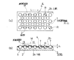
図1(a),(b)において、1は平坦なそして長手方向Lに沿って延びる基板2上に埋設される多数の同径Rの合成樹脂製ボールを示し、各種好みの硬質合成樹脂で成形できるが好ましくは外周部分をポリイミド合成樹脂で成形するのが好ましい。
【0009】
そして、基板2の下部を構成する下板2aの上には半球凹状に穿った多数の凹処3に回転自在に合成樹脂製ボール1を整然と長手方向に沿って多数列配設すると共に上板2bによって各ボール1の上部を、それぞれのボール1が同一の突出高さhを保持するように、多数の孔4を穿って被覆してボール1を回転自在に支持させるものである。
【0010】
したがって、この所望の被搬送物M、例えばI.C部品その他好みの製品,部品を合成樹脂製ボール1上に載置させれば被搬送物Mの下面は、複数の合成樹脂ボール1の周面頂部Tで点的に接触して支持される。
【0011】
この基板2が下向きに傾斜させてあれば、被搬送物Mの重力により下向きの力が働くので合成樹脂製ボール1を自転させて前方に移送できるし、また基板2を密閉された筒状体(図示せず)内に収納し、基板2の長手方向Lに向う吸収またはブローを与えることにより、被搬送物Mは吸引または風力で押されて前記したと同様に合成樹脂製ボール1を自転させて移送される。
【0012】
図2は図1の構成に駆動手段を設けた場合を示す要部断面図である。
【0013】
すなわち、基板21の下側に設けられる下板2cに図1の上板2bと同様に孔5を穿ち、下板2cの下方に合成樹脂製ボール1の下部を臨ませ、ベルト6と駆動ロール7及びガイドロール8などよりなる駆動手段Dを設けて、前記ベルト6を合成樹脂製ボール1と接触させて合成樹脂製ボール1を等速で一定方向に回転させることにより、自走機能を与えたものである。
【0014】
なお、駆動ロール7は、モータと直結または減速歯車機構を介して正逆方向への回転力が与えられる。9は駆動手段Dを遮蔽する下カバーを示す。
【0015】
したがって、被搬送物Mが極めて軽量なものなど自重での移送が円滑に行われない場合など駆動手段Dを働かせて一定速度で一定方向に被搬送物Mを移送させることができる。
【0016】
さらに、図4及び図5に基づいて他の形態について説明する。
【0017】
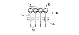
この形態は、前記形態に示す合成樹脂製ボール1は勿論のこと、金属製ボールなど好みの材質のボール1aを用い、多数の連続して列なるボール1aを無端環状の軌道3A内を順次と転動できる構成となっている。そしてこの軌道3Aは、並列して二以上設けられているが、図示では4列で構成されている。
【0018】
また、無端環状の軌道3Aは、処理室4A内に臨まれる上側軌道31とその下方に配設される下側軌道32とそれぞれの両端を弧状に結ぶ円弧状軌道33,34とで構成されている。
【0019】
そして、上側軌道31は、前後及び隣り合うボール1a同士で所望の被搬送物Mを載置でき、しかも上側軌道31よりボール1aが脱落しないように上部のみを突出させた構成としているが、他の軌道32,33,34は何れもボール1aが転動できる大きさのパイプ構造を備えれば良い構成となっている。
【0020】
5Aはボール1aの係止駆動回転手段であって、円弧状軌道33の内側に沿って溝51を穿ち、この溝51に沿ってボール1aの外形と一致して係止できる歯部52を連続して外周に形成した多数の並設したスプロケット53を係止配置し、モータなどの駆動手段を接続させて、これらのスプロケット53を図4の矢符方向に所望の速度で回転させて働かせるものである。
【0021】
なお、図において符号41Aは、被搬送物M用の処理室4Aの入口、42Aはその出口を夫々示す。
【0022】
叙上の構成になるので、処理室4A内に収納してボール1a上に配置された被搬送物Mは、スプロケット53の係止駆動回転手段5Aの働きによって矢符方向に転動するボール1aの作用で、前方に無理なく移動される。
【0023】
ボール1aは、互いに前後に接触した形で無端環状の軌道3A内を転動するので、そのボール1a上に載置された被搬送物Mは抵抗なく移送される。
【0024】
次に、図7に示す形態について説明する。
【0025】
この形態は、前記形態のうち、ボール1aを磁性金属で構成したボール1bを用い、駆動手段に永久磁石とか電磁石などの磁気吸着機能を有する回転体61を前記のスプロケット53に代えて配設したものである。
【0026】
この磁気吸着機能を有する回転体61の磁気吸着駆動手段6Aは、円弧状軌道33に溝を設ける必要なく、非磁性体の円弧状のパイプ軌道33aとすることにより、磁気カップリング構成を保持して間接的な磁気連結駆動を可能とするもので、ボール1bを密閉されたパイプ状の下側軌道32、左右の円弧状軌道33a,34内を転動移動させることができるという特徴を有する。
【0027】
上述の構成を下に、以下、本発明の実施例を説明する。
【0028】
図3(a),(b)は、この合成樹脂製ボールローラー搬送システムの一実施の形態を示す平面図と側面断面図である。
【0029】
この実施の形態は、基板が円形状の基板22を形成し、図2と同様の孔4aを穿った上板22bと孔5aを穿った下板22aとによって構成され、多数の同一径Rの合成樹脂製ボール1が基板22上に均一に分散して配設してあり、基板22の表面より、すべて同一の高さhを保持して各ボール1の上部が臨まれると共に、下板22aの下部にもボール1の下部を突出臨ませてある。
【0030】
そして、下板22aの下方には回転円板10が配設され、前記多数のボール1の周面下部と摺接している。
【0031】
この回転円板10はモータ11と直結または減速歯車機構を介して連結され、駆動手段Eを構成している。そして回転円板10を正逆に回転できるようになっており、同一の角速度で回転するため外周位置のボール1と内周位置のボール1とは異なった周速度で回転できる。12は基板22の下部の駆動手段Eを遮蔽する下カバーを示す。
【0032】
叙上の構成に成るので、この円形状の基板22上の外周に被搬送物を載置すれば、外周部分に配設されるボール1は各ボール1の中心からの距離の大小で周速度が異なるので、外周上を一定方向に回転されて移送されると共に、中心部分に載置すれば、被搬送物それ自体を回転させることができる。
【0033】
したがって回転させながら加熱,焼成などの各種作業を行わせることができる。
【0034】
なお、合成樹脂製ボール1は、同一素材による合成樹脂組成物で成形することは勿論のこと、これに代えて中心部分は硬い材料(金属も含む)を用い、外周のみを比較的柔らかい合成樹脂材料を用いた二層ないし多層構造体としても実施できる。
【0035】
また、多数の合成樹脂ボール1は長手方向に対して二列,四列などその配列は何等特定されない。
【0036】
【発明の効果】
この発明によれば、搬送用のボールが、被搬送物との接触部分はボール表面の頂部と点的接触によってフラットに支持できるので、搬送が効率良く行われ、被搬送物を傷つけるという虞れを回避できるという効果がある。
【0037】
また、駆動手段によって回転方向に対して無理なく搬送させることができるという効果がある。
【図面の簡単な説明】
【図1】 (a)はこの発明に係る基本構造のボールローラー搬送システムの一部の平面図、(b)はその側断面図
【図2】 他の形態を示す要部の断面図
【図3】 (a)は本発明の一実施例を示すボールローラー搬送システムの一形態を示す平面図、(b)は側面断面図
【図4】 図1,図2とは異なる他の形態を示す断面説明図
【図5】 図4のV−V線断面図
【図6】 図4のVI−VI線断面図
【図7】 さらに他の形態を示す要部の断面図
【符号の説明】
1 合成樹脂製ボール
1a ボール
2,21,22 基板
2a,2c,22a 下板
2b,22b 上板
D,E 駆動手段
T 周面頂部
3A 無端環状の軌道
4A 処理室
5A 係止駆動回転手段
53 スプロケット
6A 磁気吸着駆動手段[0001]
BACKGROUND OF THE INVENTION
The present invention relates to a ball roller transport system that is made of a synthetic resin or a magnetic metal, omits the use of a lubricating oil, and has high efficiency.
[0002]
[Prior art]
This type of ball roller transport system is exclusively made of metal, reducing the frictional force so as not to damage the contact partner, prevent rust, and prevent lubrication such as grease. Oil application was essential.
[0003]
[Problems to be solved by the invention]
By the way, the application of lubricating oil such as grease essential for using such conventional metal balls has the following disadvantages: (1) It takes a very long time to apply uniform and minimal grease; (2) There is a problem that the grease itself becomes particles due to aging and causes defects in the product. Furthermore, the conventional metal-based wear powder (particles) In the case of C production or the like, there are many problems in the metal vapor deposition apparatus in a vacuum clean state, especially the problem of giving serious trouble because it is an electrical conductor.
[0004]
This invention is made by paying attention to the above points. The ball is made of synthetic resin, particularly polyimide synthetic resin, and the magnetic metal is used to eliminate the use of lubricating oil such as particles. It is an object of the present invention to provide a ball roller transport system that can improve inconvenience in use based on generation and can efficiently and efficiently transfer articles and the like.
[0005]
[Means for Solving the Problems]
The present invention solves the above problems by adopting the following configuration.
[0006]
(1) A ball in which a
[0007]
DETAILED DESCRIPTION OF THE INVENTION
Hereinafter, prior to describing the embodiments of the present invention will be describes the basic structure Nitsu.
[0008]
1 (a) and 1 (b),
[0009]
On the lower plate 2a constituting the lower portion of the
[0010]
Therefore, this desired transported object M, e.g. If a C part or other desired product or part is placed on the
[0011]
If the
[0012]
FIG. 2 is a cross-sectional view of the main part showing a case where a driving means is provided in the configuration of FIG.
[0013]
That is, a hole 5 is made in the lower plate 2c provided on the lower side of the substrate 21 in the same manner as the
[0014]
The drive roll 7 is given a rotational force in the forward and reverse directions through a direct connection with the motor or through a reduction gear mechanism.
[0015]
Accordingly, the transported object M can be transported in a constant direction at a constant speed by operating the driving means D, such as when the transported object M is not very light and is not smoothly transferred.
[0016]
Further, it described otherwise state on the basis of FIGS.
[0017]
Shape status of this, the front Symbol form
[0018]
The endless annular track 3A is composed of an
[0019]
The
[0020]
[0021]
In the figure, reference numeral 41A denotes an inlet of the
[0022]
Since the above-described configuration is adopted, the transferred object M accommodated in the
[0023]
Since the
[0024]
Next, it is shown to form state is described in FIG.
[0025]
Shape status of this, among the pre-Symbol shape state, using a
[0026]
The magnetic attraction drive means 6A of the rotating body 61 having the magnetic attraction function does not need to provide a groove in the arc-shaped
[0027]
The embodiment of the present invention will be described below with the above-described configuration.
[0028]
3A and 3B are a plan view and a side sectional view showing an embodiment of the synthetic resin ball roller transport system.
[0029]
In this embodiment, a
[0030]
A
[0031]
The
[0032]
Since the structure is as described above, if the object to be transported is placed on the outer periphery of the
[0033]
Therefore, various operations such as heating and baking can be performed while rotating.
[0034]
In addition, the
[0035]
In addition, the arrangement of the many
[0036]
【The invention's effect】
According to the present invention, since the portion of the ball for transportation that is in contact with the object to be conveyed can be supported flat by point contact with the top of the ball surface, the conveyance can be efficiently performed and the object to be conveyed may be damaged. There is an effect that can be avoided.
[0037]
In addition, there is an effect that, depending on the drive means can be transported without difficulty for the rotation Direction.
[Brief description of the drawings]
1A is a plan view of a part of a basic structure of a ball roller transport system according to the present invention, FIG. 1B is a sectional side view thereof, and FIG. 2 is a sectional view of an essential part showing another embodiment. 3 (a) is a plan view showing an embodiment of a ball roller transportation system according to an embodiment of the present invention, the (b) is a side sectional view [4] Figure 1, different other forms state and FIG. 2 cross-sectional view and FIG. 5 sectional view taken along line V-V of Figure 4 Figure 6 VI-VI line sectional view of FIG. 4 [7] cross-sectional view of a main part showing another form status [code description that ]
1 Plastic ball
D, E drive means
T circumference top
3A endless ring raceway
4A treatment room
5A Locking drive rotation means
53 Sprocket
6A Magnetic adsorption drive means
Claims (1)
Priority Applications (1)
| Application Number | Priority Date | Filing Date | Title |
|---|---|---|---|
| JP17408297A JP4138909B2 (en) | 1997-06-30 | 1997-06-30 | Ball roller transport system |
Applications Claiming Priority (1)
| Application Number | Priority Date | Filing Date | Title |
|---|---|---|---|
| JP17408297A JP4138909B2 (en) | 1997-06-30 | 1997-06-30 | Ball roller transport system |
Publications (2)
| Publication Number | Publication Date |
|---|---|
| JPH1111620A JPH1111620A (en) | 1999-01-19 |
| JP4138909B2 true JP4138909B2 (en) | 2008-08-27 |
Family
ID=15972345
Family Applications (1)
| Application Number | Title | Priority Date | Filing Date |
|---|---|---|---|
| JP17408297A Expired - Fee Related JP4138909B2 (en) | 1997-06-30 | 1997-06-30 | Ball roller transport system |
Country Status (1)
| Country | Link |
|---|---|
| JP (1) | JP4138909B2 (en) |
Families Citing this family (7)
| Publication number | Priority date | Publication date | Assignee | Title |
|---|---|---|---|---|
| ATE464255T1 (en) * | 2003-07-01 | 2010-04-15 | Iguchi Kiko Co Ltd | BALL TRANSMISSION UNIT AND BALL TABLE |
| JP4373175B2 (en) * | 2003-10-17 | 2009-11-25 | オリンパス株式会社 | Substrate transfer device |
| KR101422131B1 (en) * | 2006-07-27 | 2014-07-22 | 디아이씨 가부시끼가이샤 | Photocatalyst-containing aqueous curable coating composition and process for producing the same |
| JP5600885B2 (en) * | 2009-03-19 | 2014-10-08 | 凸版印刷株式会社 | Organic EL drying equipment |
| JP5757799B2 (en) * | 2011-06-23 | 2015-07-29 | 株式会社椿本チエイン | Transport device |
| JP5805463B2 (en) * | 2011-08-26 | 2015-11-04 | 三洋機工株式会社 | Free ball bearing placement method |
| CN107323994A (en) * | 2017-06-30 | 2017-11-07 | 福安市中虹机电技术开发有限公司 | A kind of silicon steel sheet transmits protection mechanism |
-
1997
- 1997-06-30 JP JP17408297A patent/JP4138909B2/en not_active Expired - Fee Related
Also Published As
| Publication number | Publication date |
|---|---|
| JPH1111620A (en) | 1999-01-19 |
Similar Documents
| Publication | Publication Date | Title |
|---|---|---|
| US6467609B1 (en) | Can transfer rotating plate system | |
| JP4138909B2 (en) | Ball roller transport system | |
| JPH09500235A (en) | Helical magnetic linear movement mechanism | |
| US6757936B2 (en) | Wheel of traveling structure | |
| JPH0236433B2 (en) | ||
| JP4178835B2 (en) | Branch equipment | |
| US3747736A (en) | Low profile conveyor roller | |
| JPS6474321A (en) | Bearing | |
| JP2005138918A (en) | Conveyor device | |
| JPH0122162B2 (en) | ||
| CN100457586C (en) | Universal trasnport platform apparatus | |
| JP2017100861A (en) | Transport device and transport roller | |
| US4601521A (en) | Rolling apparatus | |
| CN113859854A (en) | Bell and spigot pipeline axial conveyer and pipeline surface treatment system | |
| CN223480022U (en) | Circumferential dislocation transmission device | |
| JP2005239394A (en) | Non-contact drive type curved conveyor | |
| JPH0424181A (en) | Wall surface traveling machine | |
| JP3217300B2 (en) | Conveyor branching device | |
| JPS6233167B2 (en) | ||
| KR200311419Y1 (en) | transfer roller system for LCD borad | |
| JP2862098B2 (en) | Article transfer method and apparatus | |
| SU1235796A1 (en) | Live-roller curvilinear section of roller conveyer | |
| JPH04129919A (en) | Pallet rotating device | |
| CN2365450Y (en) | Compound single-way rolling bearing | |
| JPH07420Y2 (en) | Cylindrical parts posture conversion supply device |
Legal Events
| Date | Code | Title | Description |
|---|---|---|---|
| A621 | Written request for application examination |
Free format text: JAPANESE INTERMEDIATE CODE: A621 Effective date: 20040628 |
|
| A977 | Report on retrieval |
Free format text: JAPANESE INTERMEDIATE CODE: A971007 Effective date: 20060614 |
|
| A131 | Notification of reasons for refusal |
Free format text: JAPANESE INTERMEDIATE CODE: A131 Effective date: 20060620 |
|
| A521 | Written amendment |
Free format text: JAPANESE INTERMEDIATE CODE: A523 Effective date: 20060803 |
|
| A131 | Notification of reasons for refusal |
Free format text: JAPANESE INTERMEDIATE CODE: A131 Effective date: 20060829 |
|
| A521 | Written amendment |
Free format text: JAPANESE INTERMEDIATE CODE: A523 Effective date: 20061017 |
|
| A131 | Notification of reasons for refusal |
Free format text: JAPANESE INTERMEDIATE CODE: A131 Effective date: 20070626 |
|
| A521 | Written amendment |
Free format text: JAPANESE INTERMEDIATE CODE: A523 Effective date: 20070827 |
|
| A131 | Notification of reasons for refusal |
Free format text: JAPANESE INTERMEDIATE CODE: A131 Effective date: 20071016 |
|
| A521 | Written amendment |
Free format text: JAPANESE INTERMEDIATE CODE: A523 Effective date: 20071212 |
|
| TRDD | Decision of grant or rejection written | ||
| A01 | Written decision to grant a patent or to grant a registration (utility model) |
Free format text: JAPANESE INTERMEDIATE CODE: A01 Effective date: 20080507 |
|
| A01 | Written decision to grant a patent or to grant a registration (utility model) |
Free format text: JAPANESE INTERMEDIATE CODE: A01 |
|
| A61 | First payment of annual fees (during grant procedure) |
Free format text: JAPANESE INTERMEDIATE CODE: A61 Effective date: 20080606 |
|
| R150 | Certificate of patent or registration of utility model |
Free format text: JAPANESE INTERMEDIATE CODE: R150 |
|
| FPAY | Renewal fee payment (event date is renewal date of database) |
Free format text: PAYMENT UNTIL: 20110613 Year of fee payment: 3 |
|
| FPAY | Renewal fee payment (event date is renewal date of database) |
Free format text: PAYMENT UNTIL: 20110613 Year of fee payment: 3 |
|
| FPAY | Renewal fee payment (event date is renewal date of database) |
Free format text: PAYMENT UNTIL: 20120613 Year of fee payment: 4 |
|
| FPAY | Renewal fee payment (event date is renewal date of database) |
Free format text: PAYMENT UNTIL: 20130613 Year of fee payment: 5 |
|
| R250 | Receipt of annual fees |
Free format text: JAPANESE INTERMEDIATE CODE: R250 |
|
| LAPS | Cancellation because of no payment of annual fees |