JP4138899B2 - Phase difference detection apparatus, position detection system and method for position detection - Google Patents
Phase difference detection apparatus, position detection system and method for position detection Download PDFInfo
- Publication number
- JP4138899B2 JP4138899B2 JP29978196A JP29978196A JP4138899B2 JP 4138899 B2 JP4138899 B2 JP 4138899B2 JP 29978196 A JP29978196 A JP 29978196A JP 29978196 A JP29978196 A JP 29978196A JP 4138899 B2 JP4138899 B2 JP 4138899B2
- Authority
- JP
- Japan
- Prior art keywords
- signal
- phase
- electrical
- data
- detection
- Prior art date
- Legal status (The legal status is an assumption and is not a legal conclusion. Google has not performed a legal analysis and makes no representation as to the accuracy of the status listed.)
- Expired - Lifetime
Links
Images

Classifications
-
- G—PHYSICS
- G01—MEASURING; TESTING
- G01D—MEASURING NOT SPECIALLY ADAPTED FOR A SPECIFIC VARIABLE; ARRANGEMENTS FOR MEASURING TWO OR MORE VARIABLES NOT COVERED IN A SINGLE OTHER SUBCLASS; TARIFF METERING APPARATUS; MEASURING OR TESTING NOT OTHERWISE PROVIDED FOR
- G01D5/00—Mechanical means for transferring the output of a sensing member; Means for converting the output of a sensing member to another variable where the form or nature of the sensing member does not constrain the means for converting; Transducers not specially adapted for a specific variable
- G01D5/12—Mechanical means for transferring the output of a sensing member; Means for converting the output of a sensing member to another variable where the form or nature of the sensing member does not constrain the means for converting; Transducers not specially adapted for a specific variable using electric or magnetic means
- G01D5/14—Mechanical means for transferring the output of a sensing member; Means for converting the output of a sensing member to another variable where the form or nature of the sensing member does not constrain the means for converting; Transducers not specially adapted for a specific variable using electric or magnetic means influencing the magnitude of a current or voltage
- G01D5/20—Mechanical means for transferring the output of a sensing member; Means for converting the output of a sensing member to another variable where the form or nature of the sensing member does not constrain the means for converting; Transducers not specially adapted for a specific variable using electric or magnetic means influencing the magnitude of a current or voltage by varying inductance, e.g. by a movable armature
- G01D5/204—Mechanical means for transferring the output of a sensing member; Means for converting the output of a sensing member to another variable where the form or nature of the sensing member does not constrain the means for converting; Transducers not specially adapted for a specific variable using electric or magnetic means influencing the magnitude of a current or voltage by varying inductance, e.g. by a movable armature by influencing the mutual induction between two or more coils
- G01D5/2073—Mechanical means for transferring the output of a sensing member; Means for converting the output of a sensing member to another variable where the form or nature of the sensing member does not constrain the means for converting; Transducers not specially adapted for a specific variable using electric or magnetic means influencing the magnitude of a current or voltage by varying inductance, e.g. by a movable armature by influencing the mutual induction between two or more coils by movement of a single coil with respect to two or more coils
-
- H—ELECTRICITY
- H03—ELECTRONIC CIRCUITRY
- H03M—CODING; DECODING; CODE CONVERSION IN GENERAL
- H03M1/00—Analogue/digital conversion; Digital/analogue conversion
- H03M1/12—Analogue/digital converters
- H03M1/64—Analogue/digital converters with intermediate conversion to phase of sinusoidal or similar periodical signals
- H03M1/645—Analogue/digital converters with intermediate conversion to phase of sinusoidal or similar periodical signals for position encoding, e.g. using resolvers or synchros
Description
【0001】
【発明の属する技術分野】
この発明は、レゾルバあるいはシンクロのような回転位置検出器、あるいはそれと同様の位置検出原理に従う直線位置検出器など、回転位置及び直線位置のどちらについても適用できる位置検出のための位相差検出装置及び位置検出システム並びに方法に関し、特に電気的位相差に基づきアブソリュート位置検出を行なう技術に関する。
【0002】
【従来の技術】
誘導型の回転位置検出器として、1相励磁入力で2相出力(サイン相とコサイン相の出力)を生じるものは「レゾルバ」として知られており、1相励磁入力で3相出力(120度ずれた3相)を生じるものは「シンクロ」として知られている。最も古いタイプの在来型のレゾルバは、ステータ側に90度の機械角で直交する2極(サイン極とコサイン極)の2次巻線を配し、ロータ側に1次巻線を配したものである(1次と2次の関係は逆も可)。このようなタイプのレゾルバはロータの1次巻線に電気的にコンタクトするためのブラシを必要としているので、これが欠点となっている。これに対して、ブラシを不要としたブラシレス・レゾルバの存在も知られている。ブラシレス・レゾルバは、ロータ側においてブラシに代わる回転トランスを設けたものである。
【0003】
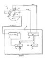
1相励磁入力で2相出力を生じるレゾルバを用いて、位置検出データをディジタルで得る検出システムとして、R/Dコンバータの存在が古くから知られている。図6は、そのようなR/Dコンバータにおける検出システムを例示するブロック図である。センサ部1としてレゾルバが用いられており、検出回路部2から発生された1相の励磁信号(例えば、−cosωt)を1次巻線W1に与え、2相の各2次巻線W2s,W2cの出力信号を検出回路部2に入力する。各相2次巻線W2s,W2cの出力信号は、ロータの回転角θに対応するサイン値 sinθとコサイン値 cosθを振幅係数に持つ誘導信号であり、例えば、それぞれ「sinθ・sinωt」及び「cosθ・sinωt」で表わせる。検出回路部2では、順次位相発生回路3から位相角φのディジタルデータを発生し、サイン・コサイン発生回路4から該位相角φに対応するサイン値sinφとコサイン値cosφのアナログ信号を発生する。乗算器5では、センサ部1からのサイン相出力信号「sinθ・sinωt」に対してサイン・コサイン発生回路4からのコサイン値cosφを乗算し、「cosφ・sinθ・sinωt」を得る。もう一方の乗算器6では、センサ部1からのコサイン相出力信号「cosθ・sinωt」に対してサイン・コサイン発生回路4からのサイン値sinφを乗算し、「sinφ・cosθ・sinωt」を得る。引算器7で、両乗算器5,6の出力信号の差を求め、この引算器7の出力によって順次位相発生回路3の位相発生動作を次のように制御する。すなわち、順次位相発生回路3の発生位相角φを最初は0にリセットし、以後順次増加していき、引算器7の出力が0になったとき増加を停止する。引算器7の出力が0になるのは、「cosφ・sinθ・sinωt」=「sinφ・cosθ・sinωt」が成立したときであり、すなわち、φ=θが成立し、順次位相発生回路3から位相角φのディジタルデータが回転角θのディジタル値に一致している。従って、この検出システムにおいては、任意のタイミングで周期的にリセットトリガを与えて順次位相発生回路3の発生位相角φを0にリセットして、該位相角φのインクメントを開始し、引算器7の出力が0になったとき、該インクメントを停止し、検出角度θのディジタルデータを得る。
【0004】
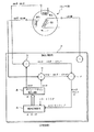
一方、レゾルバの励磁方式を、2相励磁入力で1相出力を生じるように変更して、回転角度θに応じた電気的位相ずれ角を含む出力信号を得ることにより、検出角度θのディジタルデータを得る方式も知られている。図7はそのような位相差検出システムを例示するものである。センサ部1としてレゾルバが用いられており、検出回路部8から発生された2相の励磁信号(例えばsinωtと−cosωt)を1次巻線W1s,W1cに夫々与え、1相の2次巻線W2の出力信号を検出回路部8に入力する。2次巻線W2の出力信号は、ロータの回転角θに対応する電気的位相ずれ角θを持つ誘導信号であり、例えば、便宜上sin(ωt−θ)で表わせる。検出回路部8では、カウンタ9で所定の高速クロックパルスCKをカウントし、そのカウント値を瞬時位相値としてサイン・コサイン発生回路10から励磁用のサイン信号sinωtとコサイン信号−cosωtを発生し、センサ部1の各1次巻線W1s,W1cに夫々与える。検出回路部8では、2次巻線W2の出力信号sin(ωt−θ)をゼロクロス検出回路11に入力し、その0位相角に応じてラッチパルスLPをラッチ回路12に与える。ラッチ回路12では、カウンタ9のカウント値をラッチパルスLPのタイミングでラッチする。カウンタ9のモジュロ数は、励磁用のサイン信号sinωtの1周期に対応しており、そのカウント値の0は、該サイン信号sinωtの0位相に対応している。従って、出力信号sin(ωt−θ)の0位相に対応してラッチしたラッチ回路12の内容は、該サイン信号sinωtの0位相から出力信号sin(ωt−θ)の0位相までの位相ずれ角θに一致している。このような位相差検出システムの具体例は、例えば、米国特許第4,754,220号や、米国特許第4,297,698号などにおいても同様のものが示されている。
【0005】
【発明が解決しようとする課題】
ところで、センサ部1の巻線は、周辺環境の温度変化の影響を受けてそのインピーダンスが変化し、2次側に誘導される交流信号の電気的位相が該温度変化に応じて微妙に変動する。また、センサ部1と検出回路部2又は8との間の配線長の長短や各種の回路動作遅れなど、その他の種々の、検出対象位置以外の要因の影響を受けて、検出回路部2又は8の側において受信される誘導交流信号の電気的位相が変動する。このような温度変化等の、検出対象位置以外の要因に基づく位相変動分を便宜上「±d」で示すと、図6に示したような前者の検出システムにおいては、引算器7における演算内容は、「cosφ・sinθ・sin(ωt±d)−sinφ・cosθ・sin(ωt±d)」となり、変動分「±d」が事実上相殺されて、検出精度に対して全く影響を与えないことが分かる。従って、図6に示したような前者の検出システムは、周辺環境の温度変化の影響を受けない、精度のよいシステムであることが理解できる。しかし、その反面、この検出システムにおいては、任意のタイミングで周期的にリセットトリガを与えて順次位相発生回路3の発生位相角φを0にリセットして、該位相角φのインクメントを開始し、引算器7の出力が0になったとき、該インクメントを停止し、検出角度θのディジタルデータを得るようにした、いわば逐次的なインクメント方式であるため、リセットトリガが与えられたときからφがθに一致するまでの時間待ちをすることが要求されるものであり、高速応答性に乏しいという欠点がある。
【0006】
一方、図7に示したような後者の検出システムにおいては、温度変化等の、検出対象位置以外の要因に基づく位相変動分「±d」に応じて、2次巻線の出力信号は、sin(ωt±d−θ)となり、ゼロクロス検出回路11で検出される0位相点は、本来のsin(ωt−θ)の場合の0位相点よりも、「±d」だけずれることになる。従って、ラッチ回路12でラッチされるデータは、本来のθに対応するデータではなく、「±d−θ」に対応する値となってしまい、変動分「±d」が検出誤差としてそっくり顕在化してしまう、という重大な問題点がある。その反面、ラッチパルスLPに応じて検出角度に対応するデータを即座にラッチすることができるので、高速応答性に優れているという利点があるが、上記のような温度変化等の、検出対象位置以外の要因に基づく、誤差は致命的である。
この発明は上述の点に鑑みてなされたもので、温度変化等によるセンサ側のインピーダンス変化や、その他の検出対象位置以外の要因に基づく位相変動の影響を受けることなく高精度の位置検出が可能であり、かつ、高速応答性にも優れた、位置検出用の位相差検出装置及び位置検出システムを提供しようとするものである。
【0007】
【課題を解決するための手段】
請求項1に係る位置検出用の位相差検出装置は、所定周波数の基準交流信号によって励磁され、検出対象位置に対応するサイン関数値を振幅係数として振幅変調された第1の交流出力信号及び前記検出対象位置に対応するコサイン関数値を振幅係数として振幅変調された第2の交流出力信号を出力する位置センサから、該第1の交流出力信号及び第2の交流出力信号が入力され、該入力された信号に基づいて生成した測定用信号の前記基準交流信号に対する位相差を検出する、位置検出用の位相差検出装置であって、前記第1及び第2の交流出力信号に基づき、前記検出対象位置に対応して前記基準交流信号に対して正方向にシフトされた電気的位相角を持つ第1の電気的交流信号と、同じ前記検出対象位置に対応して前記基準交流信号に対して負方向にシフトされた電気的位相角を持つ第2の電気的交流信号とを、前記測定用信号として、生成する回路と、前記基準交流信号と前記第1の電気的交流信号との電気的位相差を測定し、正の検出対象位置成分(+θ)のみならず誤差成分(d)も含んでいる第1の位相データを求める手段と、前記基準交流信号と前記第2の電気的交流信号との電気的位相差を測定し、負の検出対象位置成分(−θ)のみならず上記と同じ誤差成分(d)も含んでいる第2の位相データを求める手段と、前記第1の位相データと第2の位相データとを加算又は減算することに基づき、前記誤差成分(d)を除去した前記検出対象位置成分(θ)に対応する位置検出データを算出する手段とを備えることを特徴とする。
以下で説明する実施例において、位相差検出装置は、検出対象位置(x)に対応するサイン関数値(sinθ)を振幅係数として振幅変調された第1の交流出力信号(sinθ・sinωt)及び前記検出対象位置(x)に対応するコサイン関数値(cosθ)を振幅係数として振幅変調された第2の交流出力信号(cosθ・sinωt)を出力する位置センサ(10)から、該第1の交流出力信号及び第2の交流出力信号を入力する入力手段と、前記入力手段によって入力した前記第1の交流出力信号の電気的位相を所定角度(π/2)ずらしたもの(sinθ・cosωt)と前記第2の交流出力信号(cosθ・sinωt)とを加算又は減算することにより、前記検出対象位置に対応する電気的位相角を持つ少なくとも1つの電気的交流信号(sin(ωt+θ))を合成する電気的回路手段(14,15,16)と、前記電気的回路手段で合成した前記少なくとも1つの電気的交流信号における電気的位相ずれを測定することに基づき前記検出対象位置に対応する位置検出データ(θ)を得る演算手段(17,18,19,20,21,22;18,20,41,42,43,44,45)とを具えたことを特徴とする。なお、ここで、括弧内に示した符号は、後述する実施例における対応する信号や回路等を参考のために付記したものである。
【0008】
検出対象位置(x)に対応して異なる2つの関数値に従って振幅変調された2つの交流出力信号(sinθ・sinωt及びcosθ・sinωt)を出力する位置センサ(10)は、例えばレゾルバのように、公知である。本発明では、このような公知の位置センサ(10)の出力信号(つまり検出対象位置に応じた位相変調がなされていない出力信号)を入力して、位相差検出を行なうことができるようにして、位相差検出に基づくアブソリュート位置検出を行なうことができるようにしたことを特徴としている。
【0009】
すなわち、位置センサ(10)から入力した前記第1の交流出力信号の電気的位相を所定角度ずらしたもの(sinθ・cosωt)と前記第2の交流出力信号(cosθ・sinωt)とを加算又は減算することにより、前記検出対象位置に対応する電気的位相角を持つ少なくとも1つの電気的交流信号(sin(ωt+θ))を合成する。具体例としては、加算することに基づき、例えば「sinθ・cosωt+cosθ・sinωt」より、正方向に位相シフトされた第1の電気的交流信号(sin(ωt+θ))を合成することができ、また、減算することにに基づき、例えば「−sinθ・cosωt+cosθ・sinωt」より、負方向に位相シフトされた第2の電気的交流信号(sin(ωt−θ))を合成することができる。
【0010】
ここで、得られる交流信号の基本的な時間変化する瞬時位相を「ωt」で示し、温度変動等によるセンサ巻線のインピーダンス変化等、その他の検出対象位置以外の要因に基づく位相変動分を「±d」で示すと、上記第1の電気的交流信号は「sin(ωt±d+θ)」で表わすことができ、上記第2の電気的交流信号は「sin(ωt±d−θ)」で表わすことができる。このように、本来の検出対象位置(x)に対応する電気的位相差(θ)が、第1の電気的交流信号と第2の電気的交流信号とでは、正負互いに逆方向の位相シフトとして現われるようになる。これに対して、位相変動分「±d」は、第1及び第2の電気的交流信号のどちらにおいても、そのときの条件に応じて正又は負の同一方向に影響を及ぼす。従って、基準位相信号(sinωt)に対する第1及び第2の電気的交流信号の位相差「±d+θ」及び「±d−θ」を夫々測定し、これを加算又は減算等の適宜の演算処理することにより、位相変動分「±d」を相殺する若しくは抽出することができ、そのような演算処理に基づき、位相変動分「±d」を除去した、検出対象位置(x)に正確に対応した位相差(θ)の検出を行なうことができる。
【0011】
例えば、所定の基準交流信号(sinωt)と前記第1の電気的交流信号(sin(ωt±d+θ))との電気的位相差(±d+θ)を測定して第1の位相データ(D1)を求める手段と、前記所定の基準交流信号(sinωt)と前記第2の電気的交流信号(sin(ωt±d−θ))との電気的位相差(±d−θ)を測定して第2の位相データ(D2)を求める手段と、前記第1及び第2の位相データ(D1,D2)に基づき前記検出対象位置に対応する位置検出データを算出する手段とを含んでいてよい。この位置検出データを算出する手段は、前記第1及び第2の位相データ(D1,D2)の絶対値の差を計算することに基づき、誤差データ(±d)を得るようにすることができる。例えば、(D1+D2)/2の計算を行なうことにより、{(±d+θ)+(±d−θ)}/2=2(±d)/2=±dが成立し、誤差データ(±d)を求めることができる。そこで、前記第1及び第2の位相データの一方のデータから前記誤差データを取り除く演算を行なうことにより、例えば、「D1−(±d)=(±d+θ)−(±d)=+θ」により、検出対象位置(x)に正確に対応した位相差(θ)を示す位置検出データを得ることができる。
【0012】
また、別の例として、上記第1の電気的交流信号と第2の電気的交流信号との電気的位相差を直接測定することによっても、(ωt±d+θ)−(ωt±d−θ)=2θとなり、位相変動分「±d」が相殺され、検出対象位置(x)に対応する静的な電気的位相角(θ)に比例する位相差データ(2θ)のみを得ることができる。この位相差データ(2θ)は、そのまま検出対象位置(x)に比例する検出データとして使用してもよいし、あるいは、更に1/2に平均化した位相差データ(θ)を求め、これを検出対象位置(x)に比例する検出データとして使用してもよい。
【0013】
従って、本発明によれば、温度変化等によるセンサ側のインピーダンス変化や配線長の相違等、その他の検出対象位置以外の各種要因、の影響を受けることなく、高精度の位置検出が可能となる、という優れた効果を奏する。また、交流信号における位相差(θ)を測定する方式であるため、図6に示したような従来の逐次インクリメント方式によらずに、図7に示したような即座のラッチ方式を採用することができるので、高速応答性にも優れた位相差検出装置若しくは位置検出システムとすることができる。
【0014】
ところで、検出対象位置(x)が時間的に変化する場合、前記第1の電気的交流信号(sin(ωt±d+θ))と第2の電気的交流信号(sin(ωt±d−θ))の周波数又は周期が互いに逆方向に遷移することが起こる。このような動特性に対応できるようにするために、前記第1の電気的交流信号(sin(ωt±d+θ))のゼロクロスと第2の電気的交流信号(sin(ωt±d−θ))のゼロクロスとが一致することを検出する手段(23)と、前記第1及び第2の電気的交流信号のゼロクロスが一致したことが検出されたとき、所定の基準交流信号に対する前記第1及び第2の電気的交流信号の少なくとも一方の電気的位相ずれに基づくデータ(D1,D2)を誤差データ(±d)として保持する保持手段(26)とを更に具えるようにするとよい。その場合、前記演算手段では、少なくとも前記検出対象が動いているときに前記保持手段(26)に保持された前記誤差データ(±d)を用いて、前記電気的交流信号における電気的位相ずれに基づく前記位置検出データを修正する。
【0015】
すなわち、検出対象位置(x)が時間的に変化する場合、これに応じて位相シフト量θも時間的に変化するので、上記の「+θ」,「−θ」を夫々「+θ(t)」,「−θ(t)」で表わすことができる。このようにθが夫々正負逆方向に時間的に変化してゆくと、前述のような単純な加減演算のみでは、位相変動分「±d」の相殺若しくは抽出ができなくなることがあり、正確さに欠けるものとなる。そこで、このような動特性に対処するために、第1の電気的交流信号(sin(ωt±d+θ))のゼロクロスと第2の電気的交流信号(sin(ωt±d−θ))のゼロクロスとが一致することを検出し、両者のゼロクロスが一致したことが検出されたとき、所定の基準交流信号に対する前記第1及び第2の電気的交流信号の少なくとも一方の電気的位相ずれに基づくデータ(すなわち第1及び第2の位相データD1,D2の少なくとも一方)を誤差データ(±d)として保持し、少なくとも前記検出対象が動いているときに該保持された前記誤差データ(±d)を用いて、前記電気的交流信号における電気的位相ずれに基づく前記位置検出データ(すなわち第1及び第2の位相データD1,D2の少なくとも一方)を修正するようにしている。
【0016】
2つの信号のゼロクロスが一致するときは両者の位相が0で一致している瞬間であり、そのときの基準位相ωtに対する両信号の位相差「±d+θ」,「±d−θ」が等しいことを意味する。すなわち、±d+θ=±d−θが成立する瞬間であり、これが成り立つのは、θ=0のときである。従って、両者のゼロクロスが一致したことが検出されたときの第1及び第2の位相データ(D1,D2)に関して、
D1=±d+θ=D2=±d−θ=±d
の等式が成立ち、該第1及び第2の位相データ(D1,D2)の少なくとも一方に基づくデータを誤差データ(±d)として保持することができる。このようにして、位相誤差データ(±d)を抽出し、保持しておき、その後において、時々刻々と変化する第1及び第2の位相データ(D1,D2)の少なくとも一方を該保持した位相誤差データ(±d)を使用して修正するようにすれば、例えば、
D1−(±d)={±d+θ(t)}−(±d)=+θ(t)
のように、位相データ(D1)が時変動する場合であっても、位相誤差(±d)を除去した、検出対象位置(x)にのみ応答する正確な時変動位相差データ(+θ(t))を得ることができる。
【0017】
本発明の別の実施の形態として、1つの電気的交流信号(sin(ωt±d−θ))のみを合成し、位相ずれ測定のための基準位相を、位相センサ(10)の出力に基づき作り出すようにする手法がある。すなわち、位相センサ(10)の出力である前記第1の交流出力信号(sinθ・sinωt)と第2の交流出力信号(cosθ・sinωt)の両者のゼロクロスを合成することにより基準位相信号を形成する。この基準位相信号は、位相センサ(10)の出力に基づくものであるから、前記位相誤差成分(±d)を含んでおり、sin(ωt±d)に同期している。従って、この基準位相信号(sin(ωt±d))に対する前記電気的交流信号(sin(ωt±d−θ))の電気的位相ずれ(θ)を測定することにより、位相誤差成分(±d)を除去した、前記検出対象位置(x)に対応する正確な位置検出データを得ることができる。ここで特徴とする点は、前記位相センサ(10)の出力である第1の交流出力信号(sinθ・sinωt)と前記第2の交流出力信号(cosθ・sinωt)の両者のゼロクロスを合成することにより、位相差測定のための基準位相信号を形成するようにした点である。この第1及び第2の交流出力信号(sinθ・sinωt及びcosθ・sinωt)は、電気的位相において同相であり、振幅値がθに応じて異なっている。従って、両者のゼロクロスを合成するにあたっては、θに応じた振幅値sinθ及びcosθの変動の影響を受けずに、常にどちらか一方について相対的に精度の良いゼロクロス検出を行なうことができるため、合成した基準位相信号は、信頼性のある基準位相信号として利用することができる。この実施の形態によれば、位相誤差分「±d」を除去できるので、上述と同様に、温度変化等によるセンサ側のインピーダンス変化や配線長の相違等、その他の検出対象位置以外の各種要因、の影響を受けることなく、高精度の位置検出が可能であり、かつ、高速応答性にも優れた、位置検出用の位相差検出装置及び位置検出システムを提供することができる。
【0018】
本発明においては、公知のレゾルバ又はそれと同等の1相励磁/2相(若しくは多相)出力タイプの位置センサを使用することができる。すなわち、そのような位置センサは、検出対象位置(x)に対応する第1の関数値(sinθ)を振幅値として持つ第1の交流出力信号(sinθ・sinωt)及び前記検出対象位置(x)に対応する第2の関数値(cosθ)を振幅値として持つ第2の交流出力信号(cosθ・sinωt)を出力するものである。その場合、前記第1の交流出力信号(sinθ・sinωt)の電気的位相を所定角度ずらして、例えば90度ずらして、sinθ・cosωtとしたものと、前記第2の交流出力信号(cosθ・sinωt)とを加算することにより、sinθ・cosωt+cosθ・sinωt= sin(ωt+θ)のような、前記第1の電気的交流信号を合成するようにしてよいであろう。また、前記第1の交流出力信号(sinθ・sinωt)の電気的位相を所定角度ずらしたもの(sinθ・cosωt)と、前記第2の交流出力信号(cosθ・sinωt)とを減算することにより、cosθ・sinωt−sinθ・cosωt= sin(ωt−θ)のような、前記第2の電気的交流信号を合成するようにしてよいであろう。同様の適用は、シンクロのような1相励磁/3相出力タイプの位置センサを使用した場合も、適宜の設計変更により、適用可能であろう。
【0019】
上記の誤差データ(±d)が温度に相関していることを考慮すると、本発明によれば、1つの位置センサを用いて、位置データのみならず、温度データをも得ることができる位置検出システムを提供することができる。
すなわち、そのような位置検出システムは、検出対象位置に対応して互いに異なる関数値からなる振幅値によって夫々振幅変調された複数の交流出力信号を出力する位置検出手段と、前記交流出力信号のうち少なくとも1つの電気的位相を所定角度ずらすことにより第1の交流出力信号を得る位相シフト回路と、前記第1の交流出力信号と前記位置検出手段から出力される前記交流出力信号のうちの別の1つである第2の交流出力信号とを加算又は減算することに基づき前記検出対象位置に対応して正方向にシフトされた電気的位相角を持つ第1の電気的交流信号を形成し、前記第1の交流出力信号と前記第2の交流出力信号とを減算又は加算することに基づき同じ検出対象位置に対応して負方向にシフトされた電気的位相角を持つ第2の電気的交流信号を形成する電気回路と、所定の基準交流信号と前記第1の電気的交流信号との電気的位相差を測定して第1の位相データを求める手段と、前記所定の基準交流信号と前記第2の電気的交流信号との電気的位相差を測定して第2の位相データを求める手段と、前記第1及び第2の位相データの絶対値の差を計算することにより、誤差データを得る手段と、前記第1及び第2の位相データに基づき前記検出対象位置に対応する位置検出データを求める手段と、前記誤差データから温度検出データ得る手段とを具えたものである。
【0020】
【発明の実施の形態】
以下、添付図面を参照してこの発明の実施の形態を詳細に説明しよう。
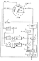
図1において、位置センサ10は、1相励磁入力/2相出力型の位置センサであり、どのようなタイプの位置センサであってもよい。例えば公知のレゾルバであってもよく、その場合、ブラシレス・レゾルバであってもよいし、ブラシのあるタイプてあってもよい。また、商品名「マイクロシン」のように、1次巻線と2次巻線をステータ側に具備し、ロータ又は可動部側には巻線を持たない、可変磁気抵抗タイプの位置センサであってもよい。また、位置センサ10は、回転位置検出センサであってもよいし、直線位置検出センサであってもよい。
位置センサ10には、検出回路部11から発生された1相の励磁用交流信号(説明の便宜上、−cosωtで示す)が印加され、これによって1次巻線W1を励磁する。位置センサ10では、この1次巻線W1の励磁に応じて2相の2次巻線W2s,W2cの夫々に交流出力信号が誘導されるようになっており、夫々の誘導電圧レベルは検出対象位置xに対応して2相の関数特性sinθ,cosθを示す。すなわち、各2次巻線W2s,W2cの誘導出力信号は、検出対象位置xに対応して2相の関数特性sinθ,cosθで振幅変調された状態で夫々出力される。ここで、x=θまたはθはxに比例しているとする。説明の便宜上、巻線の巻数等、その他の条件に従う係数は省略し、2次巻線W2sをサイン相として、その出力信号を「sinθ・sinωt」で示し、2次巻線W2cをコサイン相として、その出力信号を「cosθ・sinωt」で示す。すなわち、検出対象位置xに対応する第1の関数値sinθを振幅値として持つ第1の交流出力信号A=sinθ・sinωtが2次巻線W2sから出力され、同じ検出対象位置xに対応する第2の関数値cosθを振幅値として持つ第2の交流出力信号B=cosθ・sinωtが2次巻線W2cから出力される。
【0021】
検出回路部11では、カウンタ12で所定の高速クロックパルスCKをカウントし、そのカウント値に基づき励磁信号発生回路13から励磁用の交流信号(例えば−cosωt)を発生し、位置センサ10の1次巻線W1に与える。カウンタ12のモジュロ数は、励磁用の交流信号の1周期に対応しており、説明の便宜上、そのカウント値の0は、基準のサイン信号sinωtの0位相に対応しているものとする。例えば、カウンタ12のカウント値が0から最大値まで1巡する間で、基準のサイン信号sinωtの0位相から最大位相までの1周期が発生されると想定すると、その基準のサイン信号sinωtより90度遅れた位相で励磁用の交流信号−cosωtが、励磁信号発生回路13から発生される。
【0022】
位置センサ10から出力された第1及び第2の交流出力信号A,Bは、検出回路部11に入力される。検出回路部11において、第1の交流出力信号A=sinθ・sinωtが位相シフト回路14に入力され、その電気的位相が所定量位相シフトされ、例えば90度進められて、位相シフトされた交流信号A’=sinθ・cosωtが得られる。また、検出回路部11においては加算回路15と減算回路16とが設けられており、加算回路15では、位相シフト回路14から出力される上記位相シフトされた交流信号A’=sinθ・cosωtと位置センサ10から出力される上記第2の交流出力信号B=cosθ・sinωtとが加算され、その加算出力として、B+A’=cosθ・sinωt+sinθ・cosωt=sin(ωt+θ)なる略式で表わせる第1の電気的交流信号Y1が得られる。減算回路16では、上記位相シフトされた交流信号A’=sinθ・cosωtと上記第2の交流出力信号B=cosθ・sinωtとが減算され、その減算出力として、B−A’=cosθ・sinωt−sinθ・cosωt=sin(ωt−θ)なる略式で表わせる第2の電気的交流信号Y2が得られる。このようにして、検出対象位置(x)に対応して正方向にシフトされた電気的位相角(+θ)を持つ第1の電気的交流信号Y1=sin(ωt+θ)と、同じ前記検出対象位置(x)に対応して負方向にシフトされた電気的位相角(−θ)を持つ第2の電気的交流信号Y2=sin(ωt−θ)とが、電気的処理によって夫々得られる。
【0023】
加算回路15及び減算回路16の出力信号Y1,Y2は、夫々ゼロクロス検出回路17,18に入力され、それぞれのゼロクロスが検出される。ゼロクロスの検出の仕方としては、例えば、各信号Y1,Y2の振幅値が負から正に変化するゼロクロスつまり0位相を検出する。各回路17,18で検出したゼロクロス検出パルスつまり0位相検出パルスは、ラッチパルスLP1,LP2として、ラッチ回路19,20に入力される。ラッチ回路19,20では、カウンタ12のカウント値を夫々のラッチパルスLP1,LP2のタイミングでラッチする。前述のように、カウンタ12のモジュロ数は励磁用の交流信号の1周期に対応しており、そのカウント値の0は基準のサイン信号sinωtの0位相に対応しているものとしたので、各ラッチ回路19,20にラッチしたデータD1,D2は、それぞれ、基準のサイン信号sinωtに対する各出力信号Y1,Y2の位相ずれに対応している。各ラッチ回路19,20の出力は誤差計算回路21に入力されて、「(D1+D2)/2」の計算が行なわれる。なお、この計算は、実際は、「D1+D2」のバイナリデータの加算結果を1ビット下位にシフトすることで行われるようになっていてよい。
【0024】
ここで、位置センサ10と検出回路部11間の配線ケーブル長の長短による影響や、位置センサ10の巻線W1,W2s,W2cにおいて温度変化等によるインピーダンス変化が生じていることを考慮して、その出力信号の位相変動誤差を「±d」で示すと、検出回路部11における上記各信号は次のように表わされる。
A=sinθ・sin(ωt±d)
A’=sinθ・cos(ωt±d)
B=cosθ・sin(ωt±d)
Y1=sin(ωt±d+θ)
Y2=sin(ωt±d−θ)
D1=±d+θ
D2=±d−θ
【0025】
すなわち、各位相ずれ測定データD1,D2は、基準のサイン信号sinωtを基準位相に使用して位相ずれカウントを行なうので、上記のように位相変動誤差「±d」を含む値が得られてしまう。そこで、誤差計算回路21において、「(D1+D2)/2」の計算を行なうことにより、

【0026】
誤差計算回路21で求められた位相変動誤差「±d」のデータは、減算回路22に与えられ、一方の位相ずれ測定データD1から減算される。すなわち、減算回路22では、「D1−(±d)」の減算が行なわれるので、
D1−(±d)=±d+θ−(±d)=θ
となり、位相変動誤差「±d」を除去した正しい検出位相差θを示すディジタルデータが得られる。このように、本発明によれば、位相変動誤差「±d」が相殺されて、検出対象位置xに対応する正しい位相差θのみが抽出されることが理解できる。
【0027】
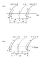
この点を図2を用いて更に説明する。図2においては、位相測定の基準となるサイン信号sinωtと前記第1及び第2の交流信号Y1,Y2の0位相付近の波形を示しており、同図(a)は位相変動誤差がプラス(+d)の場合、(b)はマイナスの場合(−d)を示す。同図(a)の場合、基準のサイン信号sinωtの0位相に対して第1の信号Y1の0位相は「θ+d」だけ進んでおり、これに対応する位相差検出データD1は「θ+d」に相当する位相差を示す。また、基準のサイン信号sinωtの0位相に対して第2の信号Y2の0位相は「−θ+d」だけ遅れており、これに対応する位相差検出データD2は「−θ+d」に相当する位相差を示す。この場合、誤差計算回路21では、
D1−(+d)=+d+θ−(+d)=θ
が計算され、正しい位相差θが抽出される。
【0028】
図2(b)の場合、基準のサイン信号sinωtの0位相に対して第1の信号Y1の0位相は「θ−d」だけ進んでおり、これに対応する位相差検出データD1は「θ−d」に相当する位相差を示す。また、基準のサイン信号sinωtの0位相に対して第2の信号Y2の0位相は「−θ−d」だけ遅れており、これに対応する位相差検出データD2は「−θ−d」に相当する位相差を示す。この場合、誤差計算回路21では、
D1−(−d)=−d+θ−(−d)=θ
が計算され、正しい位相差θが抽出される。
なお、減算回路22では。「D2−(±d)」の減算を行なうようにしてもよく、原理的には上記と同様に正しい位相差θを反映するデータ(−θ)が得られることが理解できるであろう。
【0029】
また、図2からも理解できるように、第1の信号Y1と第2の信号Y2との間の電気的位相差は2θであり、常に、両者における位相変動誤差「±d」を相殺した正確な位相差θの2倍値を示していることになる。従って、図1におけるラッチ回路19,20及び誤差計算回路21及び減算回路22等を含む回路部分の構成を、信号Y1,Y2の電気的位相差2θをダイレクトに求めるための構成に適宜変更するようにしてもよい。例えば、ゼロクロス検出回路17から出力される第1の信号Y1の0位相に対応するパルスLP1の発生時点から、ゼロクロス検出回路18から出力される第2の信号Y2の0位相に対応するパルスLP2の発生時点までの間を適宜の手段でゲートし、このゲート期間をカウントすることにより、位相変動誤差「±d」を相殺した、電気的位相差(2θ)に対応するディジタルデータを得ることができ、これを1ビット下位にシフトすれば、θに対応するデータが得られる。
【0030】
ところで、上記実施例では、+θをラッチするためのラッチ回路19と、−θをラッチするためのラッチ回路20とでは、同じカウンタ12の出力をラッチするようにしており、ラッチしたデータの正負符号については特に言及していない。しかし、データの正負符号については、本発明の趣旨に沿うように、適宜の設計的処理を施せばよい。例えば、カウンタ12のモジュロ数が4096(10進数表示)であるとすると、そのディジタルカウント0〜4095を0度〜360度の位相角度に対応させて適宜に演算処理を行なうようにすればよい。最も単純な設計例は、カウンタ12のカウント出力の最上位ビットを符号ビットとし、ディジタルカウント0〜2047を+0度〜+180度に対応させ、ディジタルカウント2048〜4095を−180度〜−0度に対応させて、演算処理を行なうようにしてもよい。あるいは、別の例として、ラッチ回路20の入力データ又は出力データを2の補数に変換することにより、ディジタルカウント4095〜0を−360度〜−0度の負の角度データ表現に対応させるようにしてもよい。
【0031】
なお、上記実施例では、1相励磁入力/2相出力型の位置センサ10を使用して、検出回路部11内の電気回路において第1の電気的交流信号Y1=sin(ωt+θ)と第2の電気的交流信号Y2=sin(ωt−θ)を形成するようにしているが、これに限らず、3相出力型又はそれ以上の多相出力型の位置センサを使用してもよい。
【0032】
ところで、検出対象位置xが静止状態のときは特に問題ないのであるが、検出対象位置xが時間的に変化するときは、それに対応する位相角θも時間的に変動することになる。その場合、加算回路15及び減算回路16の各出力信号Y1,Y2の位相ずれ量θが一定値ではなく、移動速度に対応して時間的に変化する動特性を示すものとなり、これをθ(t)で示すと、各出力信号Y1,Y2は、
Y1=sin{ωt±d+θ(t)}
Y2=sin{ωt±d−θ(t)}
となる。すなわち、基準信号sinωtの周波数に対して、進相の出力信号Y1は+θ(t)に応じて周波数が高くなる方向に周波数遷移し、遅相の出力信号Y2は−θ(t)に応じて周波数が低くなる方向に周波数遷移する。このような動特性の下においては、基準信号sinωtの1周期毎に各信号Y1,Y2の周期が互いに逆方向に次々に遷移していくので、各ラッチ回路19,20における各ラッチデータD1,D2の計測時間基準が異なってくることになり、両データD1,D2を単純に回路21,22で演算するだけでは、正確な位相変動誤差「±d」を得ることができない。
【0033】
このような問題を回避するための最も簡単な方法は、図1の構成において、検出対象位置xが時間的に動いているときの出力を無視し、静止状態のときの出力のみを用いて、静止時における検出対象位置xを測定するように装置の機能を限定することである。すなわち、そのような限定された目的のために本発明を実施するようにしてもよいものである。
しかし、検出対象がモータ回転軸のような場合は、時々刻々のモータ回転位置を検出する必要があるので、検出対象位置xが時間的に変化している最中であっても時々刻々の該検出対象位置xに対応する位相差θを正確に検出できるようにすることが望ましい。そこで、上記のような問題点を解決するために、検出対象位置xが時間的に変化している最中であっても時々刻々の該検出対象位置xに対応する位相差θを検出できるようにした本発明の改善策について図3を参照して説明する。
【0034】
図3は、図1の検出回路部11における誤差計算回路21と減算回路22の部分の変更例を抽出して示しており、他の図示していない部分の構成は図1と同様であってよい。検出対象位置xが時間的に変化している場合における該検出対象位置xに対応する位相差θを、+θ(t)および−θ(t)で表わすと、各出力信号Y1,Y2は前記のように表わせる。そして、夫々に対応してラッチ回路19,20で得られる位相ずれ測定値データD1,D2は、
D1=±d+θ(t)
D2=±d−θ(t)
となる。
【0035】
この場合、±d+θ(t) は、θの時間的変化に応じて、プラス方向に0度から360度の範囲で繰り返し時間的に変化してゆく。また、±d−θ(t) は、θの時間的変化に応じて、マイナス方向に360度から0度の範囲で繰り返し時間的に変化してゆく。従って、±d+θ(t) ≠ ±d−θ(t) のときもあるが、両者の変化が交差するときもあり、そのときは±d+θ(t) = ±d−θ(t) が成立する。このように、±d+θ(t) = ±d−θ(t) が成立するときは、各出力信号Y1,Y2の電気的位相が一致しており、かつ、夫々のゼロクロス検出タイミングに対応するラッチパルスLP1,LP2の発生タイミングが一致していることになる。
【0036】
図3において、一致検出回路23は、各出力信号Y1,Y2ののゼロクロス検出タイミングに対応するラッチパルスLP1,LP2の発生タイミングが、一致したことを検出し、この検出に応答して一致検出パルスEQPを発生する。一方、時変動判定回路24では、適宜の手段により(例えば一方の位相差測定データD1の値の時間的変化の有無を検出する等の手段により)、検出対象位置xが時間的に変化するモードであることを判定し、この判定に応じて時変動モード信号TMを出力する。
誤差計算回路21と減算回路22との間にセレクタ25が設けられており、上記時変動モード信号TMが発生されていないとき、つまりTM=“0”すなわち検出対象位置xが時間的に変化していないとき、セレクタ入力Bに加わる誤差計算回路21の出力を選択して減算回路22に入力する。このようにセレクタ25の入力Bが選択されているときの図3の回路は、図1の回路と等価的に動作する。すなわち、検出対象位置xが静止しているときは、誤差計算回路21の出力データがセレクタ25の入力Bを介して減算回路22に直接的に与えられ、図1の回路と同様に動作する。
【0037】
一方、上記時変動モード信号TMが発生されているとき、つまりTM=“1”すなわち検出対象位置xが時間的に変化しているときは、セレクタ25の入力Aに加わるラッチ回路26の出力を選択して減算回路22に入力する。上記時変動モード信号TMが“1”で、かつ前記一致検出パルスEQPが発生されたとき、アンドゲート27の条件が成立して、該一致検出パルスEQPに応答するパルスがアンドゲート27から出力され、ラッチ回路26に対してラッチ命令を与える。ラッチ回路26は、このラッチ命令に応じてカウンタ12の出力カウントデータをラッチする。ここで、一致検出パルスEQPが生じるときは、カウンタ12の出力をラッチ回路19,20に同時にラッチすることになるので、D1=D2であり、ラッチ回路26にラッチするデータは、D1又はD2(ただしD1=D2)に相当している。
【0038】
また、一致検出パルスEQPは、各出力信号Y1,Y2のゼロクロス検出タイミングが一致したとき、すなわち「±d+θ(t) = ±d−θ(t)」が成立したとき、発生されるので、これに応答してラッチ回路26にラッチされるデータは、D1又はD2(ただしD1=D2)に相当しているが故に、
(D1+D2)/2
と等価である。このことは、
【0039】
こうして、検出対象位置xが時間的に変動しているときは、位相変動誤差「±d」を正確に示すデータが一致検出パルスEQPに応じてラッチ回路26にラッチされ、このラッチ回路26の出力データがセレクタ25の入力Aを介して減算回路22に与えられる。従って、減算回路22では、位相変動誤差「±d」を除去した検出対象位置xのみに正確に応答するデータθ(時間的に変動する場合はθ(t) )を得ることができる。
なお、図3において、アンドゲート27を省略して、一致検出パルスEQPを直接的にラッチ回路26のラッチ制御入力に与えるようにしてもよい。
【0040】
また、ラッチ回路26には、カウンタ12の出力カウントデータに限らず、図3で破線で示すように誤差計算回路21の出力データ「±d」をラッチするようにしてもよい。その場合は、一致検出パルスEQPの発生タイミングに対して、それに対応する誤差計算回路21の出力データの出力タイミングが、ラッチ回路19,20及び誤差計算回路21の回路動作遅れの故に、幾分遅れるので、適宜の時間遅れ調整を行なった上で、誤差計算回路21の出力をラッチ回路26にラッチするようにするとよい。
また、動特性のみを考慮して検出回路部11を構成する場合は、図3の回路21及びセレクタ25と図1の一方のラッチ回路19又は20を省略してもよいことが、理解できるであろう。
【0041】
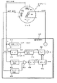
図4は、位相変動誤差「±d」を相殺することができる位相差検出演算法についての別の実施例を示し、位置センサ10は図1に示すものと同様に1相励磁入力/2相出力タイプのものが用いられる。
位置センサ10から出力される第1及び第2の交流出力信号A,Bは、検出回路部40に入力され、図1の例と同様に、第1の交流出力信号A=sinθ・sinωtが位相シフト回路14に入力され、その電気的位相が所定量位相シフトされて、位相シフトされた交流信号A’=sinθ・cosωtが得られる。また、減算回路16では、上記位相シフトされた交流信号A’=sinθ・cosωtと上記第2の交流出力信号B=cosθ・sinωtとが減算され、その減算出力として、B−A’=cosθ・sinωt−sinθ・cosωt=sin(ωt−θ)なる略式で表わせる電気的交流信号Y2が得られる。減算回路16の出力信号Y2はゼロクロス検出回路18に入力され、ゼロクロス検出に応じてラッチパルスLP2が出力され、ラッチ回路20に入力される。
【0042】
図4の実施例が図1の実施例と異なる点は、検出対象位置に対応する電気的位相ずれを含む交流信号Y2=sin(ωt−θ)から、その位相ずれ量θを測定する際の基準位相が相違している点である。図1の例では、位相ずれ量θを測定する際の基準位相は、基準のサイン信号sinωtの0位相であり、これは、位置センサ10に入力されるものではないので、温度変化等による巻線インピーダンス変化やその他の各種要因に基づく位相変動誤差「±d」を含んでいないものである。そのために、図1の例では、2つの交流信号Y1=sin(ωt+θ)及びY2=sin(ωt−θ)を形成し、その電気的位相差を求めることにより、位相変動誤差「±d」を相殺するようにしている。これに対して、図4の実施例では、位置センサ10から出力される第1及び第2の交流出力信号A,Bを基にして、位相ずれ量θを測定する際の基準位相を形成し、該基準位相そのものが上記位相変動誤差「±d」を含むようにすることにより、上記位相変動誤差「±d」を排除するようにしている。
【0043】
すなわち、検出回路部40において、位置センサ10から出力された前記第1及び第2の交流出力信号A,Bがゼロクロス検出回路41,42に夫々入力され、それぞれのゼロクロスが検出される。なお、ゼロクロス検出回路41,42は、入力信号A,Bの振幅値が負から正に変化するゼロクロス(いわば0位相)と正から負に変化するゼロクロス(いわば180度位相)のどちらにでも応答してゼロクロス検出パルスを出力するものとする。これは信号A,Bの振幅の正負極性を決定するsinθとcosθがθの値に応じて任意に正又は負となるため、両者の合成に基づき360度毎のゼロクロスを検出するためには、まず180度毎のゼロクロスを検出する必要があるためである。両ゼロクロス検出回路41,42から出力されるゼロクロス検出パルスがオア回路43でオア合成され、該オア回路43の出力が適宜の1/2分周パルス回路44(例えばT−フリップフロップのような1/2分周回路とパルス出力用アンドゲートを含む)に入力されて、1つおきに該ゼロクロス検出パルスが取り出され、360度毎のゼロクロスすなわち0位相のみに対応するゼロクロス検出パルスが基準位相信号パルスRPとして出力される。この基準位相信号パルスRPは、カウンタ45のリセット入力に与えられる。カウンタ45は所定のクロックパルスCKを絶えずカウントするものであるが、そのカウント値が、前記基準位相信号パルスRPに応じて繰返し0にリセットされる。このカウンタ45の出力がラッチ回路20に入力され、前記ラッチパルスLP2の発生タイミングで、該カウント値が該ラッチ回路20にラッチされる。ラッチ回路20にラッチしたデータDが、検出対象位置xに対応した位相差θの測定データとして出力される。
【0044】
位置センサ10から出力される第1及び第2の交流出力信号A,Bは、それぞれ、A=sinθ・sinωt、B=cosθ・sinωt、であり、電気的位相は同相である。従って、同じタイミングでゼロクロスが検出されるはずであるが、振幅係数がサインsinθ及びコサインcosθで変動するので、どちらかの振幅レベルが0か又は0に近くなる場合があり、そのような場合は、一方については、事実上、ゼロクロスを検出することができない。そこで、この実施例では、2つの交流出力信号A=sinθ・sinωt、B=cosθ・sinωtのそれぞれについてゼロクロス検出処理を行ない、両者のゼロクロス検出出力をオア合成することにより、どちらか一方が振幅レベル小によってゼロクロス検出不能であっても、他方の振幅レベル大の方のゼロクロス検出出力信号を利用できるようにしたことを特徴としている。
【0045】
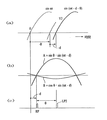
図4の例の場合、位置センサ10の巻線インピーダンス変化等による位相変動誤差が、例えば「−d」であるとすると、減算回路16から出力される交流信号Y2は、図5の(a)に示すように、Y2=sin(ωt−d−θ)となる。この場合、位置センサ10の出力信号A,Bは、角度θに応じた振幅値sinθ及びcosθを夫々持ち、図5の(b)に例示するように、A=sinθ・sin(ωt−d)、B=cosθ・sin(ωt−d)、というように位相変動誤差分を含んでいる。従って、このゼロクロス検出に基づいて図5の(c)のようなタイミングで得られる基準位相信号パルスRPは、本来の基準のサイン信号sinωtの0位相から位相変動誤差−dだけずれたものである。従って、この基準位相信号パルスRPを基準として、減算回路16の出力交流信号Y2=sin(ωt−d−θ)の位相ずれ量を測定すれば、位相変動誤差−dを除去した正確な値θが得られることになる。
【0046】
なお、位置センサ10を回転型センサとして構成する場合、位相角θが1回転につき1周期の変化を示すものに限らず、1回転につき多周期の変化を示すような高分解能タイプの回転センサが各種公知であり、そのような高分解能タイプの回転センサについても本発明を適用できるのは勿論である。また、検出対象回転軸の回転が異なる変速比で伝達される複数の回転位置センサを設けることにより、複数回転にわたる絶対的回転位置を検出可能にする技術が公知であり、そのような場合においても、各回転位置センサの位置検出データを位相差検出方式によって求める場合に、本発明が適用できる。勿論、回転型の検出装置に限らず、直線位置検出装置においても、その直線位置検出データを位相差検出方式によって求める全ての場面において本発明が適用可能である。
【0047】
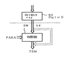
なお、センサ10の巻線部に接続される配線長等の装置条件が定まると、そのインピーダンス変化は主に温度に依存することになる。そうすると、上記位相変動誤差±dは、位置検出装置が配備された周辺環境の温度を示すデータに相当する。従って、図1又は図3の実施例のような位相変動誤差±dを演算する回路21を有するものにおいては、そこで求めた位相変動誤差±dのデータを温度検出データとして適宜出力することができる。例えば、図8に示すように、回路21の出力データ±dを処理回路28に入力し、センサ10の巻線部に接続される配線長等の諸条件をパラメータPARAとして入力して、適宜の演算処理を行えば、温度を示すデータTEMを得ることができる。勿論、データ±dそのものが温度に相関しているので、温度検出精度に絶対的精度が要求されないような場合には、データ±dを温度データTEMとしてそのまま使用してもよい。
【0048】
従って、図8に例示したような本発明の構成によれば、1つの位置検出装置によって検出対象の位置を検出することができるのみならず、周辺環境の温度を示すデータTEMをも得ることができる、という優れた効果を有するものであり、今までにない多用途タイプのセンサを提供することができるものである。
なお、上記各実施例に示した各回路は、ディスクリート回路に限らず、ゲートアレイ等を用いた集積回路によって構成することができるし、あるいはディジタルシグナルプロセッサを使用した回路によっても構成できるし、その他の高密度集積回路によっても構成することができるし、また、CPU等を使用したソウトウェアプログラムによって実現することがてき、それらのすべての実施の形態が本発明の範囲に含まれる。
【0049】
【発明の効果】
以上の通り、この発明によれば、温度変化等によるセンサ側のインピーダンス変化や配線ケーブル長の長短の影響を受けることなく、検出対象位置に応答した高精度の検出が可能となる、という優れた効果を奏する。また、交流信号における位相差を測定する方式であるため、高速応答性にも優れた検出を行なうことができる。さらに、1つのセンサを用いて、位置検出のみならず、温度検出も可能となる。
【図面の簡単な説明】
【図1】 本発明に係る位置検出システムの一実施例を示すブロック図。
【図2】 図1の動作説明図。
【図3】 本発明に係る位置検出システムの他の実施例を示すブロック図。
【図4】 本発明に係る位置検出システムの更に別の変更例を示すブロック図。
【図5】 図4の動作説明図。
【図6】 従来技術の一例を示すブロック図。
【図7】 従来技術の別の例を示すブロック図。
【図8】 図1又は図3の回路に付加可能な温度検出用の回路の一例を示すブロック図。
【符号の説明】
10 位置センサ
11,40 検出回路部
12 カウンタ
13 励磁信号発生回路
14 位相シフト回路
15 加算回路
16 減算回路
17,18 ゼロクロス検出回路
19,20 ラッチ回路
21 誤差計算回路
22 減算回路[0001]
BACKGROUND OF THE INVENTION
The present invention relates to a phase difference detection device for position detection that can be applied to both a rotational position and a linear position, such as a rotational position detector such as a resolver or a synchro, or a linear position detector according to the same position detection principle. The present invention relates to a position detection system and method, and more particularly to a technique for performing absolute position detection based on an electrical phase difference.
[0002]
[Prior art]
An inductive rotational position detector that produces two-phase output (sine phase and cosine phase output) with one-phase excitation input is known as a “resolver”, and three-phase output (120 degrees with one-phase excitation input) What produces the three shifted phases) is known as “synchro”. The oldest conventional resolver has a secondary winding (sine pole and cosine pole) orthogonal to each other at a mechanical angle of 90 degrees on the stator side, and a primary winding on the rotor side. (The relationship between primary and secondary can be reversed). This type of resolver is disadvantageous because it requires a brush to make electrical contact with the rotor primary winding. On the other hand, the existence of a brushless resolver that does not require a brush is also known. The brushless resolver is provided with a rotary transformer in place of the brush on the rotor side.
[0003]
The existence of an R / D converter has long been known as a detection system that digitally obtains position detection data using a resolver that generates a two-phase output with a one-phase excitation input. FIG. 6 is a block diagram illustrating a detection system in such an R / D converter. A resolver is used as the
[0004]
On the other hand, the resolver excitation method is changed to generate a one-phase output with a two-phase excitation input, and an output signal including an electrical phase shift angle corresponding to the rotation angle θ is obtained. There are also known methods for obtaining FIG. 7 illustrates such a phase difference detection system. A resolver is used as the
[0005]
[Problems to be solved by the invention]
By the way, the winding of the
[0006]
On the other hand, in the latter detection system as shown in FIG. 7, the output signal of the secondary winding is sin according to the phase variation “± d” based on factors other than the detection target position, such as temperature change. (Ωt ± d−θ), and the zero phase point detected by the zero
The present invention has been made in view of the above points, and can detect a position with high accuracy without being affected by a change in impedance on the sensor side due to a temperature change or the like, or other phase fluctuations based on factors other than the detection target position. In addition, the present invention intends to provide a position detection phase difference detection device and a position detection system that are excellent in high-speed response.
[0007]
[Means for Solving the Problems]
A phase difference detection device for position detection according to
In the embodiments described below, the phase difference detection device corresponds to the detection target position (x). Sign Corresponds to the first AC output signal (sinθ · sinωt) amplitude-modulated using the function value (sinθ) as an amplitude coefficient and the detection target position (x). Cosine The first AC output signal and the second AC output signal are input from a position sensor (10) that outputs a second AC output signal (cos θ · sin ωt) that is amplitude-modulated using the function value (cos θ) as an amplitude coefficient. And the second AC output signal (cosθ · sinωt) obtained by shifting the electrical phase of the first AC output signal input by the input means by a predetermined angle (π / 2) (sinθ · cosωt). ) And an electric circuit means (14, 15, 16) for synthesizing at least one electric AC signal (sin (ωt + θ)) having an electric phase angle corresponding to the position to be detected. And calculating means (17, 1) for obtaining position detection data (θ) corresponding to the position to be detected based on measuring an electrical phase shift in the at least one electrical AC signal synthesized by the electrical circuit means 8, 19, 20, 21, 22; 18, 20, 41, 42, 43, 44, 45). Here, the reference numerals in parentheses are added for reference to corresponding signals, circuits, and the like in the embodiments described later.
[0008]
A position sensor (10) that outputs two AC output signals (sinθ · sinωt and cosθ · sinωt) that have been amplitude-modulated according to two different function values corresponding to the detection target position (x) is, for example, a resolver, It is known. In the present invention, an output signal of such a known position sensor (10) (that is, an output signal that is not phase-modulated according to the detection target position) is input so that phase difference detection can be performed. The absolute position detection based on the phase difference detection can be performed.
[0009]
That is, the first AC output signal input from the position sensor (10) is added or subtracted from the first AC output signal (sinθ · cosωt) shifted by a predetermined angle and the second AC output signal (cosθ · sinωt). By doing so, at least one electrical AC signal (sin (ωt + θ)) having an electrical phase angle corresponding to the detection target position is synthesized. As a specific example, based on the addition, for example, from “sinθ · cosωt + cosθ · sinωt”, the first electrical AC signal (sin (ωt + θ)) phase-shifted in the positive direction can be synthesized. Based on the subtraction, the second electrical AC signal (sin (ωt−θ)) phase-shifted in the negative direction can be synthesized from “−sinθ · cosωt + cosθ · sinωt”, for example.
[0010]
Here, a basic time-varying instantaneous phase of the obtained AC signal is indicated by “ωt”, and a phase fluctuation amount based on other factors other than the detection target position such as a change in impedance of the sensor winding due to a temperature fluctuation or the like is expressed as “ In terms of ± d, the first electrical AC signal can be expressed as “sin (ωt ± d + θ)”, and the second electrical AC signal can be expressed as “sin (ωt ± d−θ)”. Can be represented. In this way, the electrical phase difference (θ) corresponding to the original detection target position (x) is a phase shift in the opposite direction between the first electrical AC signal and the second electrical AC signal. Appears. On the other hand, the phase variation “± d” affects both the first and second electrical AC signals in the same positive or negative direction depending on the condition at that time. Therefore, the phase differences “± d + θ” and “± d−θ” of the first and second electrical AC signals with respect to the reference phase signal (sinωt) are measured, and appropriate arithmetic processing such as addition or subtraction is performed. Accordingly, the phase variation “± d” can be canceled or extracted, and the detection target position (x) corresponding to the detection target position (x) with the phase variation “± d” removed based on such calculation processing is accurately handled. The phase difference (θ) can be detected.
[0011]
For example, by measuring an electrical phase difference (± d + θ) between a predetermined reference AC signal (sinωt) and the first electrical AC signal (sin (ωt ± d + θ)), the first phase data (D1) is obtained. Measuring means and measuring an electrical phase difference (± d−θ) between the predetermined reference AC signal (sinωt) and the second electrical AC signal (sin (ωt ± d−θ)); Means for obtaining the phase data (D2), and means for calculating position detection data corresponding to the detection target position based on the first and second phase data (D1, D2). The means for calculating the position detection data can obtain error data (± d) based on calculating a difference between absolute values of the first and second phase data (D1, D2). . For example, by calculating (D1 + D2) / 2, {(± d + θ) + (± d−θ)} / 2 = 2 (± d) / 2 = ± d holds, and error data (± d) Can be requested. Therefore, by performing an operation for removing the error data from one of the first and second phase data, for example, “D1− (± d) = (± d + θ) − (± d) = + θ”. Position detection data indicating a phase difference (θ) that accurately corresponds to the detection target position (x) can be obtained.
[0012]
As another example, (ωt ± d + θ) − (ωt ± d−θ) can also be obtained by directly measuring the electrical phase difference between the first electrical AC signal and the second electrical AC signal. = 2θ, the phase variation “± d” is canceled out, and only the phase difference data (2θ) proportional to the static electrical phase angle (θ) corresponding to the detection target position (x) can be obtained. The phase difference data (2θ) may be used as detection data proportional to the detection target position (x) as it is, or phase difference data (θ) further averaged by ½ is obtained, It may be used as detection data proportional to the detection target position (x).
[0013]
Therefore, according to the present invention, it is possible to detect a position with high accuracy without being affected by various factors other than the position to be detected, such as a change in impedance on the sensor side due to a temperature change or a difference in wiring length. , Has an excellent effect. Further, since this is a method for measuring the phase difference (θ) in the AC signal, an immediate latch method as shown in FIG. 7 should be adopted instead of the conventional sequential increment method as shown in FIG. Therefore, a phase difference detection apparatus or position detection system excellent in high-speed response can be obtained.
[0014]
By the way, when the detection target position (x) changes with time, the first electrical AC signal (sin (ωt ± d + θ)) and the second electrical AC signal (sin (ωt ± d−θ)). The frequency or the period of each of the transition occurs in the opposite directions. In order to cope with such dynamic characteristics, the zero cross of the first electrical AC signal (sin (ωt ± d + θ)) and the second electrical AC signal (sin (ωt ± d−θ)). Means (23) for detecting that the zero crossing of the first and second electric AC signals coincides with each other, and when the zero crossing of the first and second electric AC signals is detected to match, It is preferable to further comprise holding means (26) for holding data (D1, D2) based on the electric phase shift of at least one of the two electric AC signals as error data (± d). In that case, the calculation means uses the error data (± d) held in the holding means (26) at least when the detection target is moving to correct an electrical phase shift in the electrical AC signal. The position detection data based on the correction is corrected.
[0015]
That is, when the detection target position (x) changes with time, the phase shift amount θ also changes with time, so that “+ θ” and “−θ” described above are “+ θ (t)”. , “−θ (t)”. Thus, if θ changes in time in the positive and negative directions, the phase fluctuation “± d” may not be canceled or extracted only by the simple addition / subtraction operation as described above. It will be lacking. Therefore, in order to cope with such dynamic characteristics, the zero cross of the first electrical AC signal (sin (ωt ± d + θ)) and the zero cross of the second electrical AC signal (sin (ωt ± d−θ)). Is detected, and when it is detected that the zero crosses of the two coincide, data based on an electrical phase shift of at least one of the first and second electrical AC signals with respect to a predetermined reference AC signal (That is, at least one of the first and second phase data D1 and D2) is held as error data (± d), and at least the error data (± d) held when the detection target is moving is stored. The position detection data (that is, at least one of the first and second phase data D1 and D2) based on the electrical phase shift in the electrical AC signal is corrected.
[0016]
When the zero cross of the two signals coincides, it is the moment when the two phases coincide with each other, and the phase difference “± d + θ” and “± d−θ” of both signals with respect to the reference phase ωt at that time is equal. Means. That is, this is the moment when ± d + θ = ± d−θ is established, and this is true when θ = 0. Therefore, regarding the first and second phase data (D1, D2) when it is detected that the zero crosses of both coincide with each other,
D1 = ± d + θ = D2 = ± d−θ = ± d
Thus, data based on at least one of the first and second phase data (D1, D2) can be held as error data (± d). In this way, phase error data (± d) is extracted and held, and thereafter, at least one of the first and second phase data (D1, D2) that changes from moment to moment is stored in the phase. If error data (± d) is used for correction, for example,
D1− (± d) = {± d + θ (t)} − (± d) = + θ (t)
Thus, even when the phase data (D1) fluctuates over time, accurate time-varying phase difference data (+ θ (t) that responds only to the detection target position (x) with the phase error (± d) removed. )) Can be obtained.
[0017]
As another embodiment of the present invention, only one electrical AC signal (sin (ωt ± d−θ)) is synthesized, and the reference phase for phase shift measurement is based on the output of the phase sensor (10). There is a technique to make it. That is, the reference phase signal is formed by synthesizing the zero cross of both the first AC output signal (sinθ · sinωt) and the second AC output signal (cosθ · sinωt), which are the outputs of the phase sensor (10). . Since this reference phase signal is based on the output of the phase sensor (10), it includes the phase error component (± d) and is synchronized with sin (ωt ± d). Therefore, by measuring the electrical phase shift (θ) of the electrical AC signal (sin (ωt ± d−θ)) with respect to the reference phase signal (sin (ωt ± d)), the phase error component (± d ), And accurate position detection data corresponding to the detection target position (x) can be obtained. The feature here is that the zero cross of both the first AC output signal (sinθ · sinωt) and the second AC output signal (cosθ · sinωt), which are the outputs of the phase sensor (10), is synthesized. Thus, a reference phase signal for phase difference measurement is formed. The first and second AC output signals (sin θ · sin ωt and cos θ · sin ωt) are in phase in electrical phase, and the amplitude value differs depending on θ. Therefore, when synthesizing both zero crosses, it is possible to always perform relatively accurate zero cross detection for either one without being affected by fluctuations in the amplitude values sin θ and cos θ according to θ. The reference phase signal thus obtained can be used as a reliable reference phase signal. According to this embodiment, since the phase error “± d” can be removed, similarly to the above, various factors other than the detection target position, such as a change in impedance on the sensor side due to a temperature change or a difference in wiring length, etc. Thus, it is possible to provide a position detection phase difference detection device and a position detection system that are capable of highly accurate position detection without being influenced by the above and that are excellent in high-speed response.
[0018]
In the present invention, a known resolver or a position sensor of a single-phase excitation / 2-phase (or multiphase) output type equivalent to the known resolver can be used. That is, such a position sensor includes the first AC output signal (sinθ · sinωt) having the first function value (sinθ) corresponding to the detection target position (x) as an amplitude value and the detection target position (x). The second AC output signal (cos θ · sin ωt) having the second function value (cos θ) corresponding to is used as the amplitude value. In this case, the electrical phase of the first AC output signal (sinθ · sinωt) is shifted by a predetermined angle, for example, 90 ° to obtain sinθ · cosωt, and the second AC output signal (cosθ · sinωt). ) May be added to synthesize the first electrical AC signal such as sin θ · cos ωt + cos θ · sin ωt = sin (ωt + θ). Also, by subtracting the first AC output signal (sinθ · sinωt) with the electrical phase shifted by a predetermined angle (sinθ · cosωt) and the second AC output signal (cosθ · sinωt), The second electrical AC signal such as cosθ · sinωt−sinθ · cosωt = sin (ωt−θ) may be synthesized. The same application can be applied by using an appropriate design change even when a position sensor of a one-phase excitation / 3-phase output type such as a synchro is used.
[0019]
Considering that the above error data (± d) correlates with temperature, according to the present invention, position detection that can obtain not only position data but also temperature data using one position sensor is possible. A system can be provided.
That is, such a position detection system includes position detection means for outputting a plurality of AC output signals each amplitude-modulated by amplitude values composed of different function values corresponding to detection target positions, and among the AC output signals. A phase shift circuit that obtains a first AC output signal by shifting at least one electrical phase by a predetermined angle; another one of the first AC output signal and the AC output signal output from the position detection means; Forming a first electrical AC signal having an electrical phase angle shifted in a positive direction corresponding to the detection target position based on addition or subtraction with a second AC output signal that is one; Based on subtraction or addition of the first AC output signal and the second AC output signal, a second electric current having an electrical phase angle shifted in the negative direction corresponding to the same position to be detected. An electrical circuit for forming a static AC signal, means for measuring the electrical phase difference between a predetermined reference AC signal and the first electrical AC signal to obtain first phase data, and the predetermined reference AC signal And calculating the difference between the absolute values of the first and second phase data by measuring the electrical phase difference between the first and second electrical AC signals and calculating the second phase data. Means for obtaining data, means for obtaining position detection data corresponding to the position to be detected based on the first and second phase data, and means for obtaining temperature detection data from the error data.
[0020]
DETAILED DESCRIPTION OF THE INVENTION
Hereinafter, embodiments of the present invention will be described in detail with reference to the accompanying drawings.
In FIG. 1, the
The
[0021]
In the
[0022]
The first and second AC output signals A and B output from the
[0023]
The output signals Y1 and Y2 of the
[0024]
Here, in consideration of the influence of the length of the wiring cable between the
A = sin θ · sin (ωt ± d)
A ′ = sin θ · cos (ωt ± d)
B = cos θ · sin (ωt ± d)
Y1 = sin (ωt ± d + θ)
Y2 = sin (ωt ± d−θ)
D1 = ± d + θ
D2 = ± d−θ
[0025]
That is, since each phase shift measurement data D1, D2 performs phase shift count using the reference sine signal sinωt as a reference phase, a value including the phase variation error “± d” is obtained as described above. . Therefore, by calculating “(D1 + D2) / 2” in the
[0026]
The data of the phase fluctuation error “± d” obtained by the
D1− (± d) = ± d + θ− (± d) = θ
Thus, digital data indicating the correct detected phase difference θ from which the phase fluctuation error “± d” has been removed is obtained. Thus, according to the present invention, it can be understood that the phase variation error “± d” is canceled out and only the correct phase difference θ corresponding to the detection target position x is extracted.
[0027]
This point will be further described with reference to FIG. FIG. 2 shows a waveform near the zero phase of the sine signal sinωt, which is a reference for phase measurement, and the first and second AC signals Y1 and Y2, and FIG. In the case of + d), (b) shows the case of minus (-d). In the case of FIG. 5A, the zero phase of the first signal Y1 advances by “θ + d” with respect to the zero phase of the reference sine signal sinωt, and the corresponding phase difference detection data D1 becomes “θ + d”. The corresponding phase difference is shown. Further, the zero phase of the second signal Y2 is delayed by “−θ + d” with respect to the zero phase of the reference sine signal sinωt, and the corresponding phase difference detection data D2 is a phase difference corresponding to “−θ + d”. Indicates. In this case, the
D1 − (+ d) = + d + θ − (+ d) = θ
Is calculated, and the correct phase difference θ is extracted.
[0028]
In the case of FIG. 2B, the zero phase of the first signal Y1 is advanced by “θ−d” with respect to the zero phase of the reference sine signal sinωt, and the corresponding phase difference detection data D1 is “θ -D "represents the phase difference. Further, the 0 phase of the second signal Y2 is delayed by “−θ−d” with respect to the 0 phase of the reference sine signal sinωt, and the corresponding phase difference detection data D2 becomes “−θ−d”. The corresponding phase difference is shown. In this case, the
D1 − (− d) = − d + θ − (− d) = θ
Is calculated, and the correct phase difference θ is extracted.
In the
[0029]
In addition, as can be understood from FIG. 2, the electrical phase difference between the first signal Y1 and the second signal Y2 is 2θ, and it is always accurate to cancel the phase fluctuation error “± d” between the two. This indicates a double value of the phase difference θ. Accordingly, the configuration of the circuit portion including the
[0030]
In the above embodiment, the
[0031]
In the above-described embodiment, the
[0032]
Incidentally, there is no particular problem when the detection target position x is in a stationary state, but when the detection target position x changes with time, the corresponding phase angle θ also changes with time. In this case, the phase shift amount θ of each of the output signals Y1 and Y2 of the
Y1 = sin {ωt ± d + θ (t)}
Y2 = sin {ωt ± d−θ (t)}
It becomes. That is, with respect to the frequency of the reference signal sinωt, the fast-phase output signal Y1 transitions in a frequency increasing direction according to + θ (t), and the slow-phase output signal Y2 according to −θ (t). The frequency transitions in the direction of decreasing frequency. Under such dynamic characteristics, the period of each signal Y1, Y2 transitions one after another in the opposite direction for each period of the reference signal sin ωt, so that each latch data D1, The measurement time reference for D2 is different, and an accurate phase variation error “± d” cannot be obtained by simply calculating both data D1 and D2 by the
[0033]
The simplest method for avoiding such a problem is that in the configuration of FIG. 1, the output when the detection target position x is moving in time is ignored, and only the output in the stationary state is used. The function of the apparatus is limited so as to measure the detection target position x at rest. That is, the present invention may be implemented for such a limited purpose.
However, when the detection target is a motor rotation shaft, it is necessary to detect the motor rotation position every moment, so even if the detection target position x is changing temporally, It is desirable that the phase difference θ corresponding to the detection target position x can be accurately detected. Therefore, in order to solve the above-described problems, it is possible to detect the phase difference θ corresponding to the detection target position x every moment even when the detection target position x is changing in time. The improvement measures of the present invention will be described with reference to FIG.
[0034]
FIG. 3 shows an example of modification of the
D1 = ± d + θ (t)
D2 = ± d−θ (t)
It becomes.
[0035]
In this case, ± d + θ (t) repeatedly changes in time in the plus direction in the range of 0 ° to 360 ° in accordance with the time change of θ. Further, ± d−θ (t) repeatedly changes in time in the minus direction in the range of 360 degrees to 0 degrees in accordance with the time change of θ. Therefore, there are cases where ± d + θ (t) ≠ ± d−θ (t), but there are also cases where the changes of both intersect, and in this case, ± d + θ (t) = ± d−θ (t) holds. . As described above, when ± d + θ (t) = ± d−θ (t) is satisfied, the electrical phases of the output signals Y1 and Y2 coincide with each other, and the latch corresponding to the respective zero-cross detection timings. The generation timings of the pulses LP1 and LP2 are the same.
[0036]
In FIG. 3, the
A
[0037]
On the other hand, when the time variation mode signal TM is generated, that is, when TM = “1”, that is, when the detection target position x is temporally changing, the output of the
[0038]
The coincidence detection pulse EQP is generated when the zero cross detection timings of the output signals Y1 and Y2 coincide, that is, when “± d + θ (t) = ± d−θ (t)” is established. Since the data latched in the
(D1 + D2) / 2
Is equivalent to This means
[0039]
Thus, when the detection target position x fluctuates with time, data accurately indicating the phase fluctuation error “± d” is latched in the
In FIG. 3, the AND
[0040]
Further, not only the output count data of the
In addition, when the
[0041]
FIG. 4 shows another embodiment of the phase difference detection calculation method capable of canceling the phase fluctuation error “± d”, and the
The first and second AC output signals A and B output from the
[0042]
The embodiment of FIG. 4 differs from the embodiment of FIG. 1 in that the phase shift amount θ is measured from the AC signal Y2 = sin (ωt−θ) including the electrical phase shift corresponding to the detection target position. The reference phase is different. In the example of FIG. 1, the reference phase when measuring the phase shift amount θ is the zero phase of the reference sine signal sinωt, which is not input to the
[0043]
That is, in the
[0044]
The first and second AC output signals A and B output from the
[0045]
In the case of the example in FIG. 4, if the phase fluctuation error due to the winding impedance change or the like of the
[0046]
When the
[0047]
In addition, if apparatus conditions, such as the wiring length connected to the coil | winding part of the
[0048]
Therefore, according to the configuration of the present invention as illustrated in FIG. 8, not only the position of the detection target can be detected by one position detection device, but also the data TEM indicating the temperature of the surrounding environment can be obtained. It is possible to provide an unprecedented versatile type sensor.
Each circuit shown in each of the above embodiments is not limited to a discrete circuit, but can be configured by an integrated circuit using a gate array or the like, or can be configured by a circuit using a digital signal processor. The high-density integrated circuit can be realized by a software program using a CPU or the like, and all the embodiments are included in the scope of the present invention.
[0049]
【The invention's effect】
As described above, according to the present invention, it is possible to perform high-accuracy detection in response to the detection target position without being affected by impedance change on the sensor side due to temperature change or the length of the wiring cable. There is an effect. In addition, since the phase difference is measured in the AC signal, detection with excellent high-speed response can be performed. Furthermore, not only position detection but also temperature detection is possible using one sensor.
[Brief description of the drawings]
FIG. 1 is a block diagram showing an embodiment of a position detection system according to the present invention.
FIG. 2 is an operation explanatory diagram of FIG. 1;
FIG. 3 is a block diagram showing another embodiment of the position detection system according to the present invention.
FIG. 4 is a block diagram showing still another modification of the position detection system according to the present invention.
FIG. 5 is an operation explanatory diagram of FIG. 4;
FIG. 6 is a block diagram showing an example of a conventional technique.
FIG. 7 is a block diagram showing another example of the prior art.
8 is a block diagram showing an example of a temperature detection circuit that can be added to the circuit of FIG. 1 or FIG. 3;
[Explanation of symbols]
10 Position sensor
11, 40 Detection circuit section
12 counters
13 Excitation signal generation circuit
14 Phase shift circuit
15 Adder circuit
16 Subtraction circuit
17, 18 Zero cross detection circuit
19, 20 Latch circuit
21 Error calculation circuit
22 Subtraction circuit
Claims (12)
前記第1及び第2の交流出力信号に基づき、前記検出対象位置に対応して前記基準交流信号に対して正方向にシフトされた電気的位相角を持つ第1の電気的交流信号と、同じ前記検出対象位置に対応して前記基準交流信号に対して負方向にシフトされた電気的位相角を持つ第2の電気的交流信号とを、前記測定用信号として、生成する回路と、
前記基準交流信号と前記第1の電気的交流信号との電気的位相差を測定し、正の検出対象位置成分(+θ)のみならず誤差成分(d)も含んでいる第1の位相データを求める手段と、
前記基準交流信号と前記第2の電気的交流信号との電気的位相差を測定し、負の検出対象位置成分(−θ)のみならず上記と同じ誤差成分(d)も含んでいる第2の位相データを求める手段と、
前記第1の位相データと第2の位相データとを加算又は減算することに基づき、前記誤差成分(d)を除去した前記検出対象位置成分(θ)に対応する位置検出データを算出する手段と
を備える位相差検出装置。Is excited by the reference AC signal of a predetermined frequency, amplitude modulating a cosine function value corresponding to sine function value corresponding to the detected position to the first AC output signal and the detection target position that is amplitude modulated as amplitude coefficient as an amplitude coefficient The first AC output signal and the second AC output signal are input from the position sensor that outputs the second AC output signal, and the reference AC of the measurement signal generated based on the input signal is input. A phase difference detection device for position detection that detects a phase difference with respect to a signal ,
Same as the first electrical AC signal having an electrical phase angle shifted in the positive direction with respect to the reference AC signal corresponding to the detection target position based on the first and second AC output signals. A circuit that generates, as the measurement signal, a second electrical AC signal having an electrical phase angle shifted in a negative direction with respect to the reference AC signal corresponding to the detection target position;
An electrical phase difference between the reference AC signal and the first electrical AC signal is measured, and first phase data including not only a positive detection target position component (+ θ) but also an error component (d) is obtained. Means to seek,
A second electrical phase difference between the reference AC signal and the second electrical AC signal is measured , and includes not only a negative detection target position component (−θ) but also the same error component (d) as described above . Means for obtaining the phase data of
Means for calculating position detection data corresponding to the detection target position component (θ) from which the error component (d) has been removed based on adding or subtracting the first phase data and the second phase data; A phase difference detection apparatus.
前記第1及び第2の交流出力信号の一方の電気的位相を90度ずらす位相シフト回路と、
前記位相シフト回路の出力信号と前記第1及び第2の交流出力信号の他方とを加算することにより、前記検出対象位置に対応して前記基準交流信号に対して正及び負の一方向にシフトされた電気的位相角を持つ前記第1の電気的交流信号を合成する回路と、
前記位相シフト回路の出力信号と前記第1及び第2の交流出力信号の他方とを減算することにより、同じ前記検出対象位置に対応して正及び負の他方向にシフトされた電気的位相角を持つ前記第2の電気的交流信号を合成する回路と
を含む請求項1に記載の位相差検出装置。The circuit is
A phase shift circuit that shifts one electrical phase of the first and second AC output signals by 90 degrees ;
By adding the output signal of the phase shift circuit and the other of the first and second AC output signals, a shift is made in one direction positive and negative with respect to the reference AC signal corresponding to the detection target position. A circuit for synthesizing the first electrical AC signal having a specified electrical phase angle;
By subtracting the output signal of the phase shift circuit and the other of the first and second AC output signals , the electrical phase angle shifted in the other positive and negative directions corresponding to the same detection target position The phase difference detection apparatus according to claim 1, further comprising: a circuit that synthesizes the second electrical alternating current signal.
前記第1及び第2の位相データを加算することに基づき前記誤差成分(d)を示す誤差データを得る手段と、
前記第1及び第2の位相データの一方のデータから前記誤差データを取り除く演算を行なうことにより、前記位置検出データを得る手段
とを含む請求項1又は2に記載の位相差検出装置。Means for calculating the position detection data;
Means for obtaining error data indicating the error component (d) based on adding the first and second phase data;
3. The phase difference detection apparatus according to claim 1, further comprising means for obtaining the position detection data by performing an operation of removing the error data from one of the first and second phase data.
前記第1及び第2の電気的交流信号のゼロクロスが一致したことが検出されたとき、前記基準交流信号に対する前記第1及び第2の電気的交流信号の少なくとも一方の電気的位相ずれに基づくデータを誤差データとして保持する保持手段とを更に具え、
前記位置検出データを算出する手段は、少なくとも前記検出対象が動いているときに前記保持手段に保持された前記誤差データを用いて、前記電気的交流信号における電気的位相ずれに基づく前記位置検出データを修正する手段を含むものである
請求項1に記載の位相差検出装置。Means for detecting that a zero cross of the first electrical AC signal matches a zero cross of the second electrical AC signal;
Data based on an electrical phase shift of at least one of the first and second electrical AC signals with respect to the reference AC signal when it is detected that zero crossings of the first and second electrical AC signals match. And holding means for holding as error data,
The means for calculating the position detection data uses at least the error data held in the holding means when the detection target is moving, and uses the position detection data based on an electrical phase shift in the electrical AC signal. The phase difference detection apparatus according to claim 1, comprising means for correcting the phase difference.
前記第1及び第2の交流出力信号の一方の電気的位相を90度ずらす位相シフト回路と、
前記位相シフト回路の出力信号と前記第1及び第2の交流出力信号の他方とを加算又は減算することにより、前記検出対象位置に対応して前記基準交流信号に対して位相シフトされた電気的位相角であって検出対象位置成分(θ)と誤差成分(d)を含む電気的位相角を持つ電気的交流信号を合成する回路と、
前記第1の交流出力信号と第2の交流出力信号の両者のゼロクロス検出信号をオア合成することに基づき、誤差成分(d)を含む基準位相信号を形成する回路と、
前記基準位相信号に対する前記電気的交流信号の電気的位相ずれを測定することに基づき、前記誤差成分(d)を除去した前記検出対象位置成分(θ)に対応する位置検出データを得る手段と
を具備する位相差検出装置。Is excited by the reference AC signal of a predetermined frequency, amplitude modulating a cosine function value corresponding to sine function value corresponding to the detected position to the first AC output signal and the detection target position that is amplitude modulated as amplitude coefficient as an amplitude coefficient The first AC output signal and the second AC output signal are input from the position sensor that outputs the second AC output signal, and the reference AC of the measurement signal generated based on the input signal is input. a phase difference detection device for position detection that detect a phase difference with respect to the signal,
A phase shift circuit that shifts one electrical phase of the first and second AC output signals by 90 degrees ;
By adding or subtracting the output signal of the phase shift circuit and the other of the first and second AC output signals , an electrical phase shifted with respect to the reference AC signal corresponding to the detection target position A circuit that synthesizes an electrical AC signal having an electrical phase angle that is a phase angle and includes a detection target position component (θ) and an error component (d) ;
A circuit for forming a reference phase signal including an error component (d) based on OR synthesis of zero cross detection signals of both the first AC output signal and the second AC output signal;
Means for obtaining position detection data corresponding to the detection target position component (θ) from which the error component (d) has been removed based on measuring an electrical phase shift of the electrical AC signal with respect to the reference phase signal; A phase difference detection apparatus provided.
前記第1及び第2の交流出力信号の一方の電気的位相を90度ずらす位相シフト回路と、
前記位相シフト回路の出力信号と前記第1及び第2の交流出力信号の他方とを加算及び減算することにより、前記検出対象位置に対応して前記基準交流信号に対して正及び負の方向に夫々位相シフトされた電気的位相角を持つ第1及び第2の電気的交流信号を夫々合成する回路と、
前記第1の電気的交流信号のゼロクロスと第2の電気的交流信号のゼロクロスとが一致することを検出する手段と、
前記基準交流信号に対する前記第1及び第2の電気的交流信号の少なくとも一方の電気的位相差を測定して検出対象位置成分(θ)と誤差成分(d)を含む位相データを求める位相測定手段と、
前記第1及び第2の電気的交流信号のゼロクロスが一致したことが検出されたとき、前記位相測定手段により測定された位相データに基づくデータを誤差データとして保持する保持手段と、
前記保持手段に保持された前記誤差データを用いて前記位相測定手段で測定された位相データを修正することにより、前記誤差成分(d)を除去した前記検出対象位置成分(θ)に対応する位置検出データを得る手段と
を具備する位相差検出装置。Is excited by the reference AC signal of a predetermined frequency, amplitude modulating a cosine function value corresponding to sine function value corresponding to the detected position to the first AC output signal and the detection target position that is amplitude modulated as amplitude coefficient as an amplitude coefficient The first AC output signal and the second AC output signal are input from the position sensor that outputs the second AC output signal, and the reference AC of the measurement signal generated based on the input signal is input. a phase difference detection device for position detection that detect a phase difference with respect to the signal,
A phase shift circuit that shifts one electrical phase of the first and second AC output signals by 90 degrees;
By adding and subtracting the output signal of the phase shift circuit and the other of the first and second AC output signals, positive and negative directions with respect to the reference AC signal corresponding to the detection target position A circuit for synthesizing the first and second electrical AC signals each having a phase- shifted electrical phase angle;
Means for detecting that a zero cross of the first electrical AC signal matches a zero cross of the second electrical AC signal;
Phase measurement means for obtaining phase data including a detection target position component (θ) and an error component (d) by measuring an electrical phase difference of at least one of the first and second electrical AC signals with respect to the reference AC signal. When,
Holding means for holding data based on the phase data measured by the phase measuring means as error data when it is detected that the zero crosses of the first and second electrical AC signals match.
A position corresponding to the detection target position component (θ) from which the error component (d) has been removed by correcting the phase data measured by the phase measuring means using the error data held in the holding means. A phase difference detection device comprising means for obtaining detection data.
前記複数の交流出力信号に基づき、前記検出対象位置に対応して前記基準交流信号に対して正方向にシフトされた電気的位相角を持つ第1の電気的交流信号と、同じ前記検出対象位置に対応して前記基準交流信号に対して負方向にシフトされた電気的位相角を持つ第2の電気的交流信号とを生成する回路と、
前記基準交流信号と前記第1の電気的交流信号との電気的位相差を測定し、正の検出対象位置成分(+θ)のみならず誤差成分(d)も含んでいる第1の位相データを求める手段と、
前記基準交流信号と前記第2の電気的交流信号との電気的位相差を測定し、負の検出対象位置成分(−θ)のみならず上記と同じ誤差成分(d)も含んでいる第2の位相データを求める手段と、
前記第1の位相データと第2の位相データとを加算又は減算することに基づき、前記誤差成分(d)を除去した前記検出対象位置成分(θ)に対応する位置検出データを算出する手段と
を具えた位置検出システム。Position detecting means for outputting a plurality of AC output signals excited by a reference AC signal of a predetermined frequency and amplitude-modulated by amplitude values each consisting of a sine function value and a cosine function value corresponding to a detection target position;
Based on the plurality of AC output signals, the same detection target position as the first electrical AC signal having an electrical phase angle shifted in the positive direction with respect to the reference AC signal corresponding to the detection target position A circuit that generates a second electrical AC signal having an electrical phase angle shifted in a negative direction with respect to the reference AC signal ,
An electrical phase difference between the reference AC signal and the first electrical AC signal is measured, and first phase data including not only a positive detection target position component (+ θ) but also an error component (d) is obtained. Means to seek,
A second electrical phase difference between the reference AC signal and the second electrical AC signal is measured , and includes not only a negative detection target position component (−θ) but also the same error component (d) as described above . Means for obtaining the phase data of
Means for calculating position detection data corresponding to the detection target position component (θ) from which the error component (d) has been removed based on adding or subtracting the first phase data and the second phase data; Position detection system.
前記第1及び第2の交流出力信号の一方の電気的位相を90度ずらす位相シフト回路と、
前記位相シフト回路の出力信号と前記第1及び第2の交流出力信号の他方とを加算又は減算することにより、前記検出対象位置に対応して前記基準交流信号に対して位相シフトされた電気的位相角であって検出対象位置成分(θ)と誤差成分(d)を含む電気的位相角を持つ検出交流信号を合成する演算回路と、
前記第1の交流出力信号と第2の交流出力信号の両者のゼロクロス検出信号をオア合成することに基づき、誤差成分(d)を含む基準位相信号を形成する回路と、
前記基準位相信号に対する前記演算回路から出力される前記検出交流信号の電気的位相ずれを測定することに基づき、前記誤差成分(d)を除去した前記検出対象位置成分(θ)に対応する位置検出データを得る回路と
を具えた位置検出システム。Position detecting means for outputting first and second AC output signals excited by a reference AC signal having a predetermined frequency and amplitude-modulated by amplitude values consisting of a sine function value and a cosine function value corresponding to the position to be detected; ,
A phase shift circuit that shifts one electrical phase of the first and second AC output signals by 90 degrees ;
More adding or subtracting the other output signal between the first and second AC output signal of the phase-shifting circuit, the phase-shifted relative to the reference AC signal in response to the detection target position electrical An arithmetic circuit that synthesizes a detection AC signal having an electrical phase angle that includes a detection target position component (θ) and an error component (d) .
A circuit for forming a reference phase signal including an error component (d) based on OR synthesis of zero cross detection signals of both the first AC output signal and the second AC output signal;
Position detection corresponding to the detection target position component (θ) from which the error component (d) has been removed based on measuring an electrical phase shift of the detected AC signal output from the arithmetic circuit with respect to the reference phase signal A position detection system comprising a circuit for obtaining data.
前記第1及び第2の交流出力信号に基づき、前記検出対象位置に対応して前記基準交流信号に対して正方向にシフトされた電気的位相角を持つ第1の電気的交流信号を生成するステップと、
前記第1及び第2の交流出力信号に基づき、同じ前記検出対象位置に対応して前記基準交流信号に対して負方向にシフトされた電気的位相角を持つ第2の電気的交流信号を生成するステップと、
前記基準交流信号と前記第1の電気的交流信号との電気的位相差を測定し、正の検出対象位置成分(+θ)のみならず誤差成分(d)も含んでいる第1の位相データを求めるステップと、
前記基準交流信号と前記第2の電気的交流信号との電気的位相差を測定し、負の検出対象位置成分(−θ)のみならず誤差成分(d)も含んでいる第2の位相データを求めるステップと、
前記第1の位相データと第2の位相データとを加算又は減算することに基づき、前記誤差成分(d)を除去した前記検出対象位置成分(θ)に対応する位置検出データを算出するステップと
を具えた位置検出方法。 A first AC output signal excited by a reference AC signal having a predetermined frequency and amplitude-modulated using a sine function value corresponding to a detection target position as an amplitude coefficient, and amplitude modulated using a cosine function value corresponding to the detection target position as an amplitude coefficient Receiving the first and second AC output signals from a position sensor that outputs the second AC output signal,
Based on the first and second AC output signals, a first electrical AC signal having an electrical phase angle shifted in a positive direction with respect to the reference AC signal corresponding to the detection target position is generated. Steps,
Based on the first and second AC output signals, a second electrical AC signal having an electrical phase angle shifted in a negative direction with respect to the reference AC signal corresponding to the same detection target position is generated. And steps to
The electrical phase difference between the said reference alternating signal first electrical AC signal is measured, a positive detection target position component (+ theta) not only the error component (d) also comprise that the first phase data Seeking steps,
Second phase data that measures an electrical phase difference between the reference AC signal and the second electrical AC signal and includes not only a negative detection target position component (−θ) but also an error component (d). A step of seeking
Calculating position detection data corresponding to the detection target position component (θ) from which the error component (d) has been removed based on adding or subtracting the first phase data and the second phase data; A position detection method.
前記第1及び第2の交流出力信号に基づき、前記検出対象位置に対応して前記基準交流 信号に対して正方向にシフトされた電気的位相角を持つ第1の電気的交流信号を生成するステップと、
前記第1及び第2の交流出力信号に基づき、同じ前記検出対象位置に対応して前記基準交流信号に対して負方向にシフトされた電気的位相角を持つ第2の電気的交流信号を生成するステップと、
前記基準交流信号に対する前記第1及び第2の電気的交流信号の少なくとも一方の電気的位相差を測定して検出対象位置成分(θ)と誤差成分(d)を含む位相データを求めるステップと、
前記第1の電気的交流信号のゼロクロスと第2の電気的交流信号のゼロクロスとが一致することを検出するステップと、
前記第1及び第2の電気的交流信号のゼロクロスが一致したことが検出されたとき、前記位相データに基づくデータを誤差データとして保持するステップと、
少なくとも前記検出対象が動いているときに、前記保持された前記誤差データを用いて前記位相データを修正することにより、前記誤差成分(d)を除去した前記検出対象位置成分(θ)に対応する位置検出データを得るステップと
を具えた位置検出方法。 A first AC output signal excited by a reference AC signal having a predetermined frequency and amplitude-modulated using a sine function value corresponding to a detection target position as an amplitude coefficient, and amplitude modulated using a cosine function value corresponding to the detection target position as an amplitude coefficient Receiving the first and second AC output signals from a position sensor that outputs the second AC output signal,
Based on the first and second AC output signals, a first electrical AC signal having an electrical phase angle shifted in a positive direction with respect to the reference AC signal corresponding to the detection target position is generated. Steps,
Based on the first and second AC output signals, a second electrical AC signal having an electrical phase angle shifted in a negative direction with respect to the reference AC signal corresponding to the same detection target position is generated. And steps to
Determining a phase data including at least one of the electrical phase difference measured and detected object position components of the first and second electrical alternating signal relative to the reference AC signal (theta) and the error component (d),
Detecting that the zero crossing of the first electrical AC signal matches the zero crossing of the second electrical AC signal;
Holding the data based on the phase data as error data when it is detected that the zero crosses of the first and second electrical AC signals match; and
Corresponding to the detection target position component (θ) from which the error component (d) has been removed by correcting the phase data using the held error data at least when the detection target is moving. A position detection method comprising: obtaining position detection data.
Applications Claiming Priority (2)
| Application Number | Priority Date | Filing Date | Title |
|---|---|---|---|
| US08/550,358 US5710509A (en) | 1995-10-30 | 1995-10-30 | Phase difference detection device for an inductive position detector |
| US08/550,358 | 1995-10-30 |
Publications (2)
| Publication Number | Publication Date |
|---|---|
| JPH09126809A JPH09126809A (en) | 1997-05-16 |
| JP4138899B2 true JP4138899B2 (en) | 2008-08-27 |
Family
ID=24196835
Family Applications (1)
| Application Number | Title | Priority Date | Filing Date |
|---|---|---|---|
| JP29978196A Expired - Lifetime JP4138899B2 (en) | 1995-10-30 | 1996-10-24 | Phase difference detection apparatus, position detection system and method for position detection |
Country Status (4)
| Country | Link |
|---|---|
| US (1) | US5710509A (en) |
| EP (1) | EP0772025B1 (en) |
| JP (1) | JP4138899B2 (en) |
| DE (1) | DE69634656T2 (en) |
Families Citing this family (41)
| Publication number | Priority date | Publication date | Assignee | Title |
|---|---|---|---|---|
| US6552666B1 (en) * | 1996-03-16 | 2003-04-22 | Atsutoshi Goto | Phase difference detection device and method for a position detector |
| JP3170449B2 (en) * | 1996-03-25 | 2001-05-28 | オークマ株式会社 | Absolute encoder |
| JP3368837B2 (en) * | 1998-08-05 | 2003-01-20 | トヨタ自動車株式会社 | Resolver signal processor |
| DE19849554C1 (en) * | 1998-10-27 | 2000-03-02 | Ruf Electronics Gmbh | Method to determine absolute position with displacement and angle transducers; involves using two mechanically coupled sensors with output signals with numbers of periods different by one |
| US6512360B1 (en) * | 1999-03-15 | 2003-01-28 | Amiteq Co., Ltd | Self-induction-type stroke sensor |
| DE60007202T2 (en) * | 1999-03-15 | 2004-11-04 | Goto, Atsutoshi, Fuchu | Inductive position detector |
| JP4355395B2 (en) * | 1999-05-19 | 2009-10-28 | 株式会社アミテック | Position detection data generation method and apparatus |
| DE19937737C2 (en) * | 1999-08-10 | 2003-10-30 | Pilz Gmbh & Co | Device for safely monitoring the rotational movement of a shaft |
| JP4601789B2 (en) * | 2000-09-11 | 2010-12-22 | 株式会社アミテック | Position detection data generation method and apparatus |
| JP3630410B2 (en) * | 2001-05-22 | 2005-03-16 | 三菱電機株式会社 | Position detection apparatus and abnormality detection apparatus |
| GB0126014D0 (en) | 2001-10-30 | 2001-12-19 | Sensopad Technologies Ltd | Modulated field position sensor |
| US7196604B2 (en) | 2001-05-30 | 2007-03-27 | Tt Electronics Technology Limited | Sensing apparatus and method |
| JP2003235285A (en) * | 2002-02-08 | 2003-08-22 | Denso Corp | Rotating direction detector for three-phase brushless dc motor |
| US7075265B2 (en) * | 2002-04-03 | 2006-07-11 | Borealis Technical Limited | High phase order electrical rotating machine with distributed windings |
| JP3847656B2 (en) * | 2002-04-25 | 2006-11-22 | 株式会社ジェイテクト | Temperature detection method in angle detection device, angle detection device, and actuator control system provided with angle detection device |
| JP4156271B2 (en) | 2002-05-16 | 2008-09-24 | 株式会社アミテック | Control unit for power steering system |
| JP3953889B2 (en) | 2002-05-29 | 2007-08-08 | 株式会社ジェイテクト | Rotation angle detector and its temperature correction method |
| WO2004036147A2 (en) | 2002-10-16 | 2004-04-29 | Tt Electronics Technology Limited | Position sensing apparatus and method |
| GB2394293A (en) | 2002-10-16 | 2004-04-21 | Gentech Invest Group Ag | Inductive sensing apparatus and method |
| JP4007197B2 (en) | 2003-01-16 | 2007-11-14 | トヨタ自動車株式会社 | Motor control device |
| GB0303627D0 (en) | 2003-02-17 | 2003-03-19 | Sensopad Technologies Ltd | Sensing method and apparatus |
| JP2005037305A (en) * | 2003-07-17 | 2005-02-10 | Sanyo Denki Co Ltd | Resolver-detected position correcting method and corrector |
| JP4269278B2 (en) * | 2004-02-02 | 2009-05-27 | 株式会社デンソー | Rotation torque direction detection device for brushless motor |
| JP4627746B2 (en) | 2005-07-19 | 2011-02-09 | 日立オートモティブシステムズ株式会社 | Phase detection circuit, resolver / digital converter using the same, and control system |
| JP4979352B2 (en) * | 2006-02-28 | 2012-07-18 | 日立オートモティブシステムズ株式会社 | Resolver / digital converter and control system using the resolver / digital converter |
| JP4926637B2 (en) * | 2006-10-05 | 2012-05-09 | 新光電機株式会社 | Displacement sensor |
| JP4991322B2 (en) * | 2006-10-30 | 2012-08-01 | 日立オートモティブシステムズ株式会社 | Displacement sensor using GMR element, angle detection sensor using GMR element, and semiconductor device used therefor |
| JP5148394B2 (en) * | 2008-07-11 | 2013-02-20 | 株式会社東芝 | Microcomputer, motor control system |
| DE102009019509B4 (en) * | 2009-04-24 | 2011-06-09 | Lenze Automation Gmbh | Method and device for determining a rotor angle of a rotating shaft |
| JP5237210B2 (en) * | 2009-06-26 | 2013-07-17 | 株式会社アミテック | Position detection device |
| JP5341832B2 (en) * | 2010-07-08 | 2013-11-13 | 愛三工業株式会社 | Rotational position sensor |
| DE102011003758B4 (en) * | 2011-02-08 | 2022-12-08 | Robert Bosch Gmbh | Method for resolver chip diagnosis, resolver chip diagnosis device and computer program product |
| US8829840B2 (en) * | 2011-04-29 | 2014-09-09 | General Electric Company | Auto-compensating system and method for condition monitoring of electrical machines |
| US9103847B2 (en) * | 2012-08-01 | 2015-08-11 | Freescale Semiconductor, Inc. | Variable reluctance sensor interface with integration based arming threshold |
| US9225225B2 (en) * | 2013-08-02 | 2015-12-29 | Hamilton Sundstrand Corporation | Sensing PM electrical machine position |
| JP6550793B2 (en) * | 2015-02-27 | 2019-07-31 | 株式会社ジェイテクト | Temperature detection device and rotation angle detection device |
| US9897469B2 (en) * | 2016-01-26 | 2018-02-20 | GM Global Technology Operations LLC | Resolver phase compensation |
| US10408643B2 (en) * | 2016-08-18 | 2019-09-10 | Texas Instruments Incorporated | Methods and apparatus to increase resolver-to-digital converter accuracy |
| WO2019155592A1 (en) * | 2018-02-09 | 2019-08-15 | 株式会社島津製作所 | Electrical conductivity detector and method for determining phase adjustment value for background subtraction signal |
| EP3937366B1 (en) * | 2020-05-28 | 2023-02-22 | Huawei Digital Power Technologies Co., Ltd. | Sampling triggering method, microprocessor, motor controller, and electric vehicle |
| WO2023147014A1 (en) * | 2022-01-27 | 2023-08-03 | Microchip Technology Incorporated | Compensation of sine-cosine coil mismatches in inductive sensors |
Family Cites Families (13)
| Publication number | Priority date | Publication date | Assignee | Title |
|---|---|---|---|---|
| GB1120342A (en) * | 1964-12-11 | 1968-07-17 | Plessey Uk Ltd | Improvements relating to synchros and the like |
| US3584783A (en) * | 1967-12-20 | 1971-06-15 | Kaijo Denki Kk | Vector synthesizer for continuously obtaining the magnitude and direction of a vector from the orthogonal components of the vector |
| US3647963A (en) * | 1969-03-10 | 1972-03-07 | Bendix Corp | Automatic coordinate determining device |
| GB1298669A (en) * | 1969-04-16 | 1972-12-06 | British Aircraft Corp Ltd | Improvements in apparatus for signalling angular displacement |
| US3851330A (en) * | 1973-02-20 | 1974-11-26 | Trw Inc | Amplitude-to-phase conversion circuit |
| US4011440A (en) * | 1975-04-29 | 1977-03-08 | General Electric Company | System for generating an angular rate signal from an angular position signal utilizing a constant amplitude-variable carrier phase signal |
| US4039946A (en) * | 1976-03-18 | 1977-08-02 | The United States Of America As Represented By The Administrator Of The National Aeronautics And Space Administration | Tachometer |
| US4297698A (en) * | 1977-11-02 | 1981-10-27 | Pneumo Corporation | 360 Degree linear variable phase transformer |
| US4612503A (en) * | 1980-10-21 | 1986-09-16 | Kabushiki Kaisha S G | Rotation speed detection device having a rotation angle detector of inductive type |
| US4468617A (en) * | 1982-02-11 | 1984-08-28 | General Electric Company | Velocity sensor and method of producing a velocity signal |
| US4468618A (en) * | 1982-10-28 | 1984-08-28 | Siemens Aktiengesellschaft | System for generating a speed-proportional voltage |
| US5066911A (en) * | 1989-04-07 | 1991-11-19 | Sundstrand Data Control, Inc. | Apparatus and method for sensing displacement using variations magnetic flux linkage |
| JP3624458B2 (en) * | 1995-04-10 | 2005-03-02 | 多摩川精機株式会社 | Digital angle detection method |
-
1995
- 1995-10-30 US US08/550,358 patent/US5710509A/en not_active Expired - Lifetime
-
1996
- 1996-10-24 JP JP29978196A patent/JP4138899B2/en not_active Expired - Lifetime
- 1996-10-26 DE DE69634656T patent/DE69634656T2/en not_active Expired - Lifetime
- 1996-10-26 EP EP96117223A patent/EP0772025B1/en not_active Expired - Lifetime
Also Published As
| Publication number | Publication date |
|---|---|
| EP0772025A1 (en) | 1997-05-07 |
| EP0772025B1 (en) | 2005-04-27 |
| DE69634656T2 (en) | 2006-03-02 |
| US5710509A (en) | 1998-01-20 |
| JPH09126809A (en) | 1997-05-16 |
| DE69634656D1 (en) | 2005-06-02 |
Similar Documents
| Publication | Publication Date | Title |
|---|---|---|
| JP4138899B2 (en) | Phase difference detection apparatus, position detection system and method for position detection | |
| JP5173962B2 (en) | Resolver / digital conversion apparatus and resolver / digital conversion method | |
| JP5802588B2 (en) | Angle detection device and motor drive control device | |
| JPH06167354A (en) | Interpolation unit for scale | |
| JP3624458B2 (en) | Digital angle detection method | |
| JP3372450B2 (en) | Encoder output signal processing device | |
| US6552666B1 (en) | Phase difference detection device and method for a position detector | |
| JP4355395B2 (en) | Position detection data generation method and apparatus | |
| US8924179B2 (en) | Assembly and method for determining an angular position | |
| JP3978268B2 (en) | Inductive position detector | |
| JPH08101045A (en) | Position detector | |
| JP4662516B2 (en) | Position detection device | |
| JP3920896B2 (en) | Linear position detector | |
| JP4048207B2 (en) | Position detection device | |
| JP3733400B2 (en) | Inclinometer | |
| JP4601789B2 (en) | Position detection data generation method and apparatus | |
| JP3733399B2 (en) | Tilt detection device | |
| JPH05256638A (en) | Position detector with error compensating function | |
| JP3733397B2 (en) | Multi-directional tilt detector | |
| JP4990390B2 (en) | Position detection device | |
| JP2003344106A (en) | Rotation angle detector | |
| JP2016020819A (en) | Angle detection device and motor drive circuit | |
| JP2001074500A (en) | Magnetic type encoder | |
| JPH0419512A (en) | Rotational angle detector | |
| JPH04130217A (en) | Rotary-angle-signal processing apparatus |
Legal Events
| Date | Code | Title | Description |
|---|---|---|---|
| A711 | Notification of change in applicant |
Free format text: JAPANESE INTERMEDIATE CODE: A711 Effective date: 20060825 |
|
| A131 | Notification of reasons for refusal |
Free format text: JAPANESE INTERMEDIATE CODE: A131 Effective date: 20070306 |
|
| A521 | Written amendment |
Free format text: JAPANESE INTERMEDIATE CODE: A523 Effective date: 20070505 |
|
| TRDD | Decision of grant or rejection written | ||
| A01 | Written decision to grant a patent or to grant a registration (utility model) |
Free format text: JAPANESE INTERMEDIATE CODE: A01 Effective date: 20080507 |
|
| A01 | Written decision to grant a patent or to grant a registration (utility model) |
Free format text: JAPANESE INTERMEDIATE CODE: A01 |
|
| A61 | First payment of annual fees (during grant procedure) |
Free format text: JAPANESE INTERMEDIATE CODE: A61 Effective date: 20080606 |
|
| R150 | Certificate of patent or registration of utility model |
Free format text: JAPANESE INTERMEDIATE CODE: R150 |
|
| FPAY | Renewal fee payment (event date is renewal date of database) |
Free format text: PAYMENT UNTIL: 20110613 Year of fee payment: 3 |
|
| FPAY | Renewal fee payment (event date is renewal date of database) |
Free format text: PAYMENT UNTIL: 20110613 Year of fee payment: 3 |
|
| S202 | Request for registration of non-exclusive licence |
Free format text: JAPANESE INTERMEDIATE CODE: R315201 |
|
| FPAY | Renewal fee payment (event date is renewal date of database) |
Free format text: PAYMENT UNTIL: 20110613 Year of fee payment: 3 |
|
| R360 | Written notification for declining of transfer of rights |
Free format text: JAPANESE INTERMEDIATE CODE: R360 |
|
| FPAY | Renewal fee payment (event date is renewal date of database) |
Free format text: PAYMENT UNTIL: 20110613 Year of fee payment: 3 |
|
| R370 | Written measure of declining of transfer procedure |
Free format text: JAPANESE INTERMEDIATE CODE: R370 |
|
| S202 | Request for registration of non-exclusive licence |
Free format text: JAPANESE INTERMEDIATE CODE: R315201 |
|
| FPAY | Renewal fee payment (event date is renewal date of database) |
Free format text: PAYMENT UNTIL: 20110613 Year of fee payment: 3 |
|
| R350 | Written notification of registration of transfer |
Free format text: JAPANESE INTERMEDIATE CODE: R350 |
|
| FPAY | Renewal fee payment (event date is renewal date of database) |
Free format text: PAYMENT UNTIL: 20110613 Year of fee payment: 3 |
|
| FPAY | Renewal fee payment (event date is renewal date of database) |
Free format text: PAYMENT UNTIL: 20120613 Year of fee payment: 4 |
|
| FPAY | Renewal fee payment (event date is renewal date of database) |
Free format text: PAYMENT UNTIL: 20130613 Year of fee payment: 5 |
|
| R250 | Receipt of annual fees |
Free format text: JAPANESE INTERMEDIATE CODE: R250 |
|
| R250 | Receipt of annual fees |
Free format text: JAPANESE INTERMEDIATE CODE: R250 |
|
| R250 | Receipt of annual fees |
Free format text: JAPANESE INTERMEDIATE CODE: R250 |
|
| R250 | Receipt of annual fees |
Free format text: JAPANESE INTERMEDIATE CODE: R250 |
|
| EXPY | Cancellation because of completion of term |