JP4138842B2 - Mounting condition determination method - Google Patents
Mounting condition determination method Download PDFInfo
- Publication number
- JP4138842B2 JP4138842B2 JP2007023550A JP2007023550A JP4138842B2 JP 4138842 B2 JP4138842 B2 JP 4138842B2 JP 2007023550 A JP2007023550 A JP 2007023550A JP 2007023550 A JP2007023550 A JP 2007023550A JP 4138842 B2 JP4138842 B2 JP 4138842B2
- Authority
- JP
- Japan
- Prior art keywords
- mounting
- equipment
- group
- component
- facility
- Prior art date
- Legal status (The legal status is an assumption and is not a legal conclusion. Google has not performed a legal analysis and makes no representation as to the accuracy of the status listed.)
- Active
Links
Images


Description
本発明は、部品実装基板の生産のための設備における実装条件を決定する実装条件決定方法に関する。 The present invention relates to a mounting condition determination method for determining a mounting condition in equipment for producing a component mounting board.
近年、部品実装基板の製造メーカ、特に大手の製造メーカでは、多種多様な部品実装基板の生産が行われている。このような製造メーカは、部品実装機などの複数の生産設備(以下、単に「設備」という。)で構成される複数の生産ライン(以下、単に「ライン」という。)により大量の部品実装基板を生産している。 In recent years, manufacturers of component mounting boards, particularly large manufacturers, produce a wide variety of component mounting boards. Such a manufacturer uses a plurality of production lines (hereinafter simply referred to as “line”) composed of a plurality of production facilities (hereinafter simply referred to as “equipment”) such as component mounting machines to produce a large number of component mounting boards. Is producing.
また、一般的に、各ラインにはそれぞれのラインを担当するオペレータが割り当てられ、各オペレータは、自身が担当するラインの各設備に対して実装条件の設定および変更等を行う。 In general, an operator who is in charge of each line is assigned to each line, and each operator sets and changes a mounting condition for each facility in the line that he / she is in charge of.
実装条件とは、部品を基板に実装するために使用するノズル等の構成要素を特定する情報や、各構成要素の動作や位置などを制御するための情報等であり、各設備において特定の値等に設定または変更することで部品実装機等の設備における生産状況を改善することが可能な情報である。 Mounting conditions are information for identifying components such as nozzles used to mount components on the board, information for controlling the operation and position of each component, etc., and specific values for each facility. It is information that can improve the production status in equipment such as a component mounter by setting or changing to the above.
このような実装条件の例としては、部品を基板に実装する際の、部品の移動速度、使用するノズル、部品寸法、部品の吸着状態等の部品に関する情報を光学的に認識するカメラ、カメラの位置、部品を照らすライト、ライトの光量、および、基板における部品の実装点の位置を示す情報等を含むNumerical Control(NC)データのそれぞれ、およびそれぞれの組み合わせなどがある。 Examples of such mounting conditions include a camera for optically recognizing information about the component such as the moving speed of the component, the nozzle to be used, the component size, and the suction state of the component when the component is mounted on the board. There are a position, a light for illuminating the component, a light amount of the light, and each of the numerical control (NC) data including information indicating the position of the mounting point of the component on the board, and combinations thereof.
各設備の実装条件を最適なものにすることで、各設備の生産性が向上し、これら設備を含む生産システム全体の生産性も向上する。 By optimizing the mounting conditions of each facility, the productivity of each facility is improved, and the productivity of the entire production system including these facilities is also improved.
そこで、これら実装条件を複数の設備で統一する技術も開示されている(例えば、特許文献1参照)。 Therefore, a technique for unifying these mounting conditions with a plurality of facilities is also disclosed (for example, see Patent Document 1).
この技術によると、設備構成が同一である複数のラインを備える生産システムにおいて、各ラインの生産状況を分析する分析装置が存在する。この分析装置は、分析した結果として問題を改善するための情報を各ラインにフィードバックすることができる。 According to this technique, in a production system including a plurality of lines having the same equipment configuration, there is an analyzer that analyzes the production status of each line. This analysis apparatus can feed back information for improving the problem as a result of the analysis to each line.
例えば、あるラインで部品の装着ミスが規定の割合以上で発生すると、分析装置がその原因を分析し、改善するための実装条件を各ラインに反映させることができる。
ここで、複数のラインを備える生産システムにおいては、上述のように、実装条件の設定等を行うオペレータがラインごとに異なることが一般的である。 Here, in a production system including a plurality of lines, as described above, it is common that operators for setting mounting conditions and the like differ for each line.
また、各ラインでは、それぞれのオペレータ独自の経験および知識に基づいて決定された実装条件が各設備に設定される。これにより、各ラインでは互いに異なる実装条件の下で部品実装基板が生産されることとなる。 In each line, the installation conditions determined based on the experience and knowledge unique to each operator are set in each facility. Thereby, component mounting boards are produced under different mounting conditions in each line.
このような場合、オペレータの知識やスキル等がそれぞれに異なることから、本来より低い生産性で稼動するラインが生ずることがある。 In such a case, since the operator's knowledge, skills, and the like are different, a line that operates with lower productivity than the original may occur.
また、例えば、部品実装機等の設備に軽微ながらも不具合があり、本来の性能を発揮できないような状況であっても、オペレータは、実装条件の何らかのパラメータを変更することで不具合をごまかしつつ稼動を継続させることがある。 In addition, for example, even if the equipment such as a component mounting machine has minor problems and cannot perform its original performance, the operator can operate while cheating the problems by changing some parameters of the mounting conditions. May be continued.
つまり、生産効率が本来あるべき値より低下したまま、かつ、軽微であるとは言え何らかの問題を抱えた状態で設備が稼動される可能性がある。 In other words, there is a possibility that the equipment may be operated in a state where the production efficiency is lower than it should be and is insignificant, although it is slight.
このように、生産システムの一部のラインが非効率的な状態であるということは生産システム全体としても非効率的な状態である。すなわち、現状では、生産システムが非効率的な稼働状況にある中で部品実装基板の生産が継続される可能性がある。 Thus, the fact that some lines of the production system are in an inefficient state is an inefficient state for the entire production system. That is, at present, there is a possibility that the production of the component mounting board may be continued while the production system is in an inefficient operation state.
そこで、上記従来の技術を用いて、このような稼働状況にある生産システムの生産性を向上させることが考えられる。しかし、上記従来の技術は、問題の発生を契機としその問題の分析と解決とを事後的に図る技術である。 Therefore, it is conceivable to improve the productivity of a production system in such an operating state using the above-described conventional technology. However, the above-described conventional technique is a technique for subsequent analysis and resolution of a problem when the problem occurs.
そのため、例えば、あるラインで装着ミスが規定の割合以上で発生するなどして初めて当該問題を解決するための措置がとられることになる。 Therefore, for example, a measure for solving the problem is not taken until a mounting error occurs in a certain line at a prescribed rate or more.
従って、例えば、ラインを構成する1つの設備において、本来あるべき生産性で稼動していない状態であっても、生産性を向上させ得る実装条件を分析装置から与えられるのを待つことになる。 Therefore, for example, even in a state where one facility constituting the line is not operating at a productivity that should be originally intended, it is awaited that a mounting condition that can improve the productivity is given from the analyzer.
そこで、早期に上記状態を改善するために、各設備において軽微なエラー等の問題が発生した場合でも、分析装置にその原因を分析させ、当該問題を改善するための実装条件を各設備にフィードバックさせることが考えられる。 Therefore, in order to improve the above conditions at an early stage, even if a problem such as a minor error occurs in each equipment, let the analyzer analyze the cause and feed back the mounting conditions for improving the problem to each equipment. It is possible to make it.
しかし、この場合、分析装置ではエラー等の分析および実装条件の生成のための処理負荷が増大する。また、各設備では、分析装置から送信される実装条件への変更処理をたびたび行う必要がある。そのため各設備における生産性が逆に低下する恐れもあり、現実的ではない。 However, in this case, the analysis apparatus increases the processing load for analyzing errors and generating mounting conditions. Moreover, in each facility, it is necessary to frequently perform a change process to the mounting condition transmitted from the analyzer. For this reason, productivity in each facility may be lowered, which is not realistic.
また、近年では、基板に実装する部品の種類に応じて、それら部品の実装に適した様々な種類の部品実装機などの設備を用意し、異なる設備構成の複数の生産ライン(以下、単に「ライン」という。)により複数種の部品実装基板が生産されている。 In recent years, depending on the type of components to be mounted on the board, various types of component mounting machines suitable for mounting these components have been prepared, and multiple production lines (hereinafter simply referred to as “ Lines ”)) produce multiple types of component mounting boards.
ここで、複数の設備の中には、同一機種であるものや、基板に実装する部品が同一であるなど共通する属性を有する設備も多数存在する。 Here, among the plurality of facilities, there are many facilities having common attributes such as the same model and the same parts mounted on the board.
このような場合、共通する属性を有する複数の設備において、機種が同一であることや、扱う部品が同じであることなどにより、本来的には最適なものに統一されるべき実装条件が多く存在する。 In such a case, there are many mounting conditions that should be unified to the optimal one by nature because of the same model and the same parts in multiple facilities with common attributes. To do.
しかしながら、上記従来の技術は、同一の設備構成からなる複数のラインの実装条件を統一することができる技術である。 However, the conventional technique is a technique that can unify the mounting conditions of a plurality of lines having the same equipment configuration.
そのため、上述のような、異なる設備構成からなる複数の生産ラインにより複数種の部品実装基板を生産する生産システムにおいては、上記従来の技術を用いることはできず、やはり、オペレータにより各設備の実装条件の設定または変更が行われることとなる。 Therefore, the above-mentioned conventional technology cannot be used in a production system that produces a plurality of types of component mounting boards using a plurality of production lines having different equipment configurations as described above. Conditions are set or changed.
また、ある部品実装機についてオペレータが変更になると、変更後のオペレータは、自身の経験および知識に基づき、当該部品実装機の調子に応じて各実装条件の適否の判断を行い、その設定を行うことがある。そのため、オペレータの変更に伴う実装条件の再設定作業等の無駄な作業が発生することとなる。 In addition, when an operator is changed for a certain component mounting machine, the changed operator determines whether each mounting condition is appropriate based on his / her experience and knowledge, and sets the setting. Sometimes. For this reason, useless work such as resetting of the mounting conditions accompanying the change of the operator occurs.
このように、複数の設備を備える生産システムにおいて、互いに異なる設備構成からなる複数の生産ラインが存在する場合においても、上記従来の技術を用いることはできない。 As described above, in the production system including a plurality of facilities, the above-described conventional technique cannot be used even when there are a plurality of production lines having different facility configurations.
そのため、各設備において、それぞれのオペレータレベルで実装条件の設定および調整がなされ、上述のような生産プロセス上の無駄や非効率性は依然として残ることとなる。 Therefore, in each facility, the mounting conditions are set and adjusted at each operator level, and the above-described waste and inefficiency in the production process still remain.
本発明は、上記従来の課題を考慮し、複数の設備を備える生産システムにおいて、各設備の生産性を効率よく向上させるための実装条件決定方法を提供することを目的とする。 In view of the above-described conventional problems, an object of the present invention is to provide a mounting condition determination method for efficiently improving the productivity of each facility in a production system including a plurality of facilities.
上記目的を達成するために、本発明の実装条件決定方法は、部品実装基板を生産するための複数の設備のうちの少なくとも1つの設備に設定される実装条件を決定する実装条件決定方法であって、前記複数の設備の中から、生産作業に関連する成績が所定の基準を満たす設備である特定設備を決定する決定ステップと、前記決定ステップにおいて決定された特定設備から前記生産作業に関連する実装条件を取得する取得ステップと、前記取得ステップにおいて取得された実装条件を、前記特定設備以外の設備に設定する設定ステップとを含む。 In order to achieve the above object, a mounting condition determining method of the present invention is a mounting condition determining method for determining a mounting condition set in at least one of a plurality of facilities for producing a component mounting board. Determining a specific facility that is a facility that satisfies a predetermined standard for results related to the production work from the plurality of facilities, and relates to the production work from the specific facility determined in the determination step The acquisition step of acquiring mounting conditions, and the setting step of setting the mounting conditions acquired in the acquiring step in equipment other than the specific equipment.
これにより、部品実装基板の生産プロセスにおける各種の生産作業に関連する成績、例えば部品の吸着、認識、基板への装着の際の成功率、または、実装条件を設定したオペレータのスキル等を指標とし、優秀な設備を特定設備と決定することができる。さらに、特定設備から当該生産作業に関連する実装条件を取得することができる。つまり、生産性を向上させ得る実装条件を取得することができる。 As a result, the results related to various production operations in the component mounting board production process, for example, the success rate when picking up and recognizing parts, mounting on the board, or the skill of the operator who set the mounting conditions are used as indicators. Excellent equipment can be determined as specific equipment. Furthermore, it is possible to acquire mounting conditions related to the production work from the specific equipment. That is, it is possible to acquire mounting conditions that can improve productivity.
従って、本発明の実装条件決定方法は、複数の設備における実装条件の最適化を図ることができる。 Therefore, the mounting condition determination method of the present invention can optimize the mounting conditions in a plurality of facilities.
また、前記複数の設備のそれぞれは、各設備の属性に応じて複数のグループのうちのいずれかのグループに属しており、前記実装条件決定方法はさらに、前記設備を識別するための識別情報に基づき、所定のグループに属する設備であるグループ内設備を識別する識別ステップを含み、前記決定ステップは、前記識別ステップにおいて識別されたグループ内設備の中から、前記特定設備を決定するとしてもよい。 Each of the plurality of facilities belongs to one of a plurality of groups according to the attribute of each facility, and the mounting condition determination method further includes identification information for identifying the facility. The identification step of identifying an in-group facility that is a facility belonging to a predetermined group may be included, and the determining step may determine the specific facility from the in-group facilities identified in the identifying step.
これにより、特定設備の決定は、設備の属性に応じて分けられたグループ単位で行われる。すなわち、各グループは、設備の機種や、基板に実装する部品の種類など、設備の属性の共通性を有している。 Thereby, the determination of specific equipment is performed in the group unit divided according to the attribute of equipment. That is, each group has the commonality of the attributes of equipment, such as the equipment model and the type of components mounted on the board.
つまり、あるグループ内において、各設備の属性が共通することにより、特定設備とグループ内設備とは、同じ実装条件を設定し得る関係にある。 That is, in a certain group, the attributes of the respective facilities are common, so that the specific equipment and the equipment in the group have a relationship in which the same mounting condition can be set.
従って、特定設備から取得された生産性を向上させ得る実装条件を各グループ内設備に設定することは、各グループ内設備の生産性を向上させる上で有効かつ効率的な行為である。 Therefore, setting the mounting conditions that can improve the productivity acquired from the specific equipment in the equipment in each group is an effective and efficient action for improving the productivity of the equipment in each group.
このように、この実装条件の最適化は、グループごとに実装条件をより良いものに統一することで行ってもよい。つまり、効率よく複数の設備に対する生産性の向上を図ることができる。 As described above, the mounting conditions may be optimized by unifying the mounting conditions for each group. That is, the productivity for a plurality of facilities can be improved efficiently.
また、本発明の実装条件決定方法は、さらに、前記設備から前記識別情報を受信する受信ステップを含み、前記識別ステップでは、前記受信ステップおいて受信される識別情報が前記所定のグループに属することを示す場合、前記設備は前記グループ内設備であると識別するとしてもよく、さらに、前記識別ステップにおいて識別されたグループ内設備から、前記成績を示す成績情報を収集する収集ステップを含み、前記決定ステップでは、前記収集ステップにおいて収集された成績情報に示される成績が前記所定の基準を満たす場合、前記グループ内設備を前記特定設備と決定するとしてもよい。 In addition, the mounting condition determining method of the present invention further includes a receiving step of receiving the identification information from the facility, wherein the identification information received in the receiving step belongs to the predetermined group. The equipment may be identified as equipment in the group, and further includes a collection step of collecting performance information indicating the results from the equipment in the group identified in the identification step, and the determination In the step, the equipment in the group may be determined as the specific equipment when the grade shown in the grade information collected in the collecting step satisfies the predetermined criterion.
これにより、例えば、設備の入れ換え等があった場合、特定設備の決定や、特定設備から取得された実装条件の他の設備への設定を即座に行うことができる。 Thereby, for example, when the equipment is replaced, the specific equipment can be determined and the mounting conditions acquired from the specific equipment can be immediately set to other equipment.
また、前記決定ステップでは、前記成績が複数のグループ内設備の中で最上位であるグループ内設備を、前記所定の基準を満たす前記特定設備と決定するとしてもよい。 Further, in the determining step, the in-group facility having the highest grade among the plurality of in-group facilities may be determined as the specific facility that satisfies the predetermined criterion.
これにより、各設備における生産性を最も向上させ得る実装条件を取得することができ、各設備に設定することができる。 Thereby, the mounting conditions that can improve the productivity in each facility most can be acquired and set in each facility.
また、前記実装条件決定方法は、前記設備において実行されるものであり、前記所定のグループは、自設備が属するグループであり、前記決定ステップでは、グループ内設備における前記成績が、自設備における前記生産作業に関連する成績より上位であるグループ内設備を、前記所定の基準を満たす前記特定設備と決定し、前記設定ステップでは、前記取得ステップにおいて取得された実装条件を、前記特定設備以外のグループ内設備である自設備に設定するとしてもよい。 Further, the mounting condition determining method is executed in the equipment, and the predetermined group is a group to which the own equipment belongs, and in the determining step, the result in the equipment in the group is obtained in the own equipment. The equipment in the group that is higher than the results related to the production work is determined as the specific equipment that satisfies the predetermined standard, and in the setting step, the mounting condition acquired in the acquisition step is set to a group other than the specific equipment. It may be set to the own equipment which is the internal equipment.
これにより、各設備が、主導的に実装条件の最適化を図ることができる。例えば、各設備の稼働状況に応じたタイミングで、実装条件をより良いものに変更することができる。 As a result, each facility can lead the optimization of mounting conditions. For example, the mounting condition can be changed to a better one at a timing according to the operating status of each facility.
また、前記実装条件決定方法は、前記設備において実行されるものであり、前記所定のグループは、自設備が属するグループであり、前記決定ステップでは、自設備における前記生産作業に関連する成績が、自設備における前記生産作業に関連する過去の成績より上位である場合、自設備を前記所定の基準を満たす前記特定設備と決定し、前記取得ステップでは、自設備から前記生産作業に関連する実装条件を取得し、前記設定ステップでは、前記実装条件を自設備以外のグループ内設備に送信することにより、前記実装条件を前記グループ内設備に設定するとしてもよい。 Further, the mounting condition determination method is executed in the equipment, the predetermined group is a group to which the own equipment belongs, and in the determining step, a result related to the production work in the own equipment is If it is higher than the past results related to the production work in the own equipment, the own equipment is determined as the specific equipment satisfying the predetermined standard, and in the acquisition step, the mounting conditions related to the production work from the own equipment In the setting step, the mounting condition may be set in the in-group facility by transmitting the mounting condition to the in-group facility other than the own facility.
これにより、例えば、実装条件の最適化を図る機能を備えていない設備に対し、自設備において実績のある実装条件を与えることができる。つまり、上記機能を有しない設備に対しても実装条件の最適化を図ることができる。 Thereby, for example, a mounting condition having a track record in its own equipment can be given to equipment that does not have a function of optimizing the mounting conditions. That is, it is possible to optimize the mounting conditions even for facilities that do not have the above functions.
また、前記複数の設備は、実装条件決定装置と通信し、前記実装条件決定方法は、前記実装条件決定装置において実行されるものであり、前記設定ステップでは、前記実装条件を前記特定設備以外のグループ内設備に送信することにより、前記実装条件を前記グループ内設備に設定するとしてもよい。 The plurality of facilities communicate with a mounting condition determining device, and the mounting condition determining method is executed in the mounting condition determining device. In the setting step, the mounting condition is set to a value other than the specific facility. The mounting condition may be set in the group equipment by transmitting to the group equipment.
これにより、各設備は実装条件の最適化を図る機能を備えることなく、実装条件の最適化が図られることとなる。また、これら設備の管理者は、各設備に対する実装条件の最適化のための機能の変更、修正等を行う場合、1つの実装条件決定装置に対して指示等を行えばよく、効率的にこれら変更等を行うことができる。また、各設備は、他の設備と情報のやり取りを行う必要がなく、例えば、各設備を接続するネットワーク回線に通信負荷を掛けることがない。 As a result, each facility can optimize the mounting conditions without having a function for optimizing the mounting conditions. In addition, when the manager of these facilities changes or corrects the function for optimizing the mounting conditions for each facility, it is sufficient to give instructions to one mounting condition determining device, and these can be efficiently performed. Changes can be made. Further, each facility does not need to exchange information with other facilities, and for example, a communication load is not imposed on a network line connecting each facility.
また、本発明の実装条件決定装置は、部品実装基板を生産するための複数の設備のうちの少なくとも1つの設備に設定される実装条件を決定する実装条件決定装置であって、前記複数の設備の中から、生産作業に関連する成績が所定の基準を満たす設備である特定設備を決定する決定手段と、前記決定手段により決定された特定設備から前記生産作業に関連する実装条件を取得する取得手段と、前記取得手段において取得された実装条件を、前記特定設備以外の設備に設定する設定手段とを備える。 Further, the mounting condition determining apparatus of the present invention is a mounting condition determining apparatus that determines a mounting condition set in at least one of a plurality of facilities for producing a component mounting board, wherein the plurality of facilities Determining means for determining the specific equipment that is the equipment satisfying a predetermined standard, and obtaining the mounting conditions related to the production work from the specific equipment determined by the determining means Means and setting means for setting the mounting condition acquired by the acquisition means in equipment other than the specific equipment.
これにより、本発明の実装条件決定装置は、各設備に対して、より生産性を向上させる実装条件を設定することができる。また、本発明の実装条件決定装置は、各設備がそれぞれ備えてもよく、各設備から独立して1つだけ存在し、各設備に対して実装条件の設定を行ってもよい。 Thereby, the mounting condition determination apparatus of this invention can set the mounting conditions which improve productivity more with respect to each installation. Moreover, the installation condition determination apparatus of the present invention may be included in each facility, or only one exists independently from each facility, and the mounting conditions may be set for each facility.
さらに、本発明は、本発明の実装条件決定方法における特徴的なステップを含むプログラムとして実現したり、そのプログラムが格納されたCD−ROM等の記憶媒体として実現したり、本発明の実装条件決定方法における特徴的なステップを実行する集積回路として実現することもできる。プログラムは、通信ネットワーク等の伝送媒体を介して流通させることもできる。 Furthermore, the present invention can be realized as a program including characteristic steps in the mounting condition determination method of the present invention, or can be realized as a storage medium such as a CD-ROM storing the program, or the mounting condition determination of the present invention. It can also be implemented as an integrated circuit that performs the characteristic steps in the method. The program can also be distributed via a transmission medium such as a communication network.
本発明は、複数の設備を備える生産システムにおいて、効率よく各設備の生産性を向上させるための実装条件決定方法を提供することができる。 The present invention can provide a mounting condition determination method for efficiently improving the productivity of each facility in a production system including a plurality of facilities.
以下、本発明の実施の形態について図面を参照しながら説明する。 Hereinafter, embodiments of the present invention will be described with reference to the drawings.
(実施の形態1)
図1は、実施の形態1における生産システムのハードウェア構成の概要を示す概要図である。
(Embodiment 1)
FIG. 1 is a schematic diagram illustrating an outline of a hardware configuration of a production system according to the first embodiment.
図1に示すように、実施の形態1における生産システム1は4つのラインで構成され、ラインごとに、そのラインが生産すべき部品実装基板における部品の種類に応じた設備構成になっている。
As shown in FIG. 1, the
本実施の形態において、これらラインを構成する複数の設備のそれぞれは部品実装機であり、各部品実装機はLocal Area Network(LAN)5を介し、情報のやり取りを行うことができる。 In the present embodiment, each of the plurality of facilities constituting these lines is a component mounter, and each component mounter can exchange information via a local area network (LAN) 5.
また、図において各部品実装機に付された“M123−1”等の記号は、部品実装機を識別するための識別情報の一種である個体コードである。個体コードにより、複数の部品実装機の中から1つの部品実装機が特定される。また、例えば、単に「M123−1」という場合、当該個体コードが付された部品実装機のことを指す。 In the figure, symbols such as “M123-1” attached to each component mounter are individual codes that are a type of identification information for identifying the component mounter. One component mounter is specified from the plurality of component mounters by the individual code. In addition, for example, simply “M123-1” indicates a component mounter to which the individual code is attached.
また、個体コードは“機種コード−設備番号”で構成されるコードであり、機種コードが同一である部品実装機は同一の機種であることを意味する。 The individual code is a code composed of “model code—equipment number”, which means that the component mounters having the same model code are the same model.
また、LAN5において各部品実装機は、個体コードを宛先として情報を送信することで、宛先となった個体コードの部品実装機にその情報を到達させることができる。このような技術として、例えば、Transmission Control Protocol/Internet Protocol(TCP/IP)におけるDomain Name System(DNS)が採用される。
Further, in the
なお、各部品実装機の機能的な構成は、個体コード“M123−1”が付された部品実装機10を例にとって、図3を用いて後述する。
The functional configuration of each component mounter will be described later with reference to FIG. 3, taking the
図1に示す複数の部品実装機は、それぞれの機種、基板に実装する部品、製造メーカ等の属性により、どのライン上にあるかに関係なくグループ分けすることができる。 The plurality of component mounters shown in FIG. 1 can be grouped regardless of which line they are on, depending on the type of each model, the components mounted on the board, the attributes of the manufacturer, and the like.
図2は、実施の形態1における生産システムを構成する部品実装機のグループ分けの一例を示す図である。 FIG. 2 is a diagram showing an example of grouping of component mounters constituting the production system in the first embodiment.
図2を示すように、生産システム1に属する部品実装機は大分類であるメーカ別のグループ(以下、「メーカグループ」という。)に分けられる。各メーカグループ内の部品実装機は、その機種により、中分類であるカテゴリ別のグループ(以下、「カテゴリグループ」という。)に分けられる。つまり、各機種は、複数のカテゴリに分けられる。
As shown in FIG. 2, the component mounters belonging to the
具体的には、各機種は、機種の類似性やそれぞれの実装態様等により複数のカテゴリに分けることができる。本実施の形態においては、各機種は、それぞれの実装態様、例えばモジュラー機であるかロータリー機であるかに応じて各カテゴリグループに分けられている。 Specifically, each model can be divided into a plurality of categories according to the similarity of models, the respective mounting modes, and the like. In the present embodiment, each model is divided into each category group according to each mounting mode, for example, a modular machine or a rotary machine.
また、カテゴリグループ内の部品実装機は小分類である機種別のグループ(以下、「機種グループ」という。)に分けられており、各部品実装機はいずれかの機種グループに属している。 In addition, the component mounters in the category group are divided into machine type groups (hereinafter referred to as “model groups”) which are sub-classifications, and each component mounter belongs to one of the model groups.
このように、各グループは、部品実装機の機種およびカテゴリ等の属性と対応付けられている。 Thus, each group is associated with attributes such as the model and category of the component mounter.
なお、図中の“AAA”等の記号は各グループを識別するためのコードである。例えば、“AAA”はA社グループを識別するためのメーカコードであり、“G−AM”はMグループを識別するためのカテゴリコードである。 A symbol such as “AAA” in the figure is a code for identifying each group. For example, “AAA” is a manufacturer code for identifying the A company group, and “G-AM” is a category code for identifying the M group.
このように、生産システム1における各部品実装機はそれぞれの製造メーカや機種等の属性によってグループ分けされており、1つのグループ内の部品実装機は、その機器構成や、基板に実装する部品の適否等の共通の属性を有している。
As described above, the component mounters in the
つまり、それぞれのグループ内の各部品実装機は、そのグループにおいて共通する属性を有していることにより、共通の実装条件を設定し得る関係にある。 In other words, the component mounters in each group have a common attribute in the group, so that a common mounting condition can be set.
例えば、ある機種グループに属する部品実装機は、機種が同一であることによりそれぞれの機器構成、性能および性質は実質的に等しいことになる。 For example, component mounters belonging to a certain model group have substantially the same device configuration, performance, and properties due to the same model.
そのため、例えばある機種グループに属する1つの部品実装機は、グループ内の他の部品実装機における使用ノズル、部品の移動速度等の実装条件を活用することができる。 Therefore, for example, one component mounter belonging to a certain model group can utilize mounting conditions such as a nozzle used in another component mounter in the group and a moving speed of components.
従って、グループ内で最適な実装条件を見つけ出せば、グループ内の全部品実装機にその実装条件を与えることで各部品実装機の生産性を向上させることができる。 Therefore, if an optimum mounting condition is found in the group, the productivity of each component mounting machine can be improved by giving the mounting condition to all the component mounting machines in the group.
図3は、実施の形態1における部品実装機の機能的な構成を示す機能ブロック図である。なお、部品実装機が本来備える電源部や部品に関する情報を光学的に認識するためのカメラ等の構成部の図示および説明は省略し、本発明の特徴を説明するための構成部について図示および説明を行う。その他の図においても同様である。 FIG. 3 is a functional block diagram showing a functional configuration of the component mounter in the first embodiment. In addition, illustration and description of components such as a camera for optically recognizing information on a power supply unit and components originally provided in the component mounter are omitted, and components and components for explaining the features of the present invention are illustrated and described. I do. The same applies to the other drawings.
図3に示す部品実装機10は、図1および図2において“M123−1”で表される部品実装機である。
A
図3に示すように、部品実装機10は、実装条件決定装置11を備えている。実装条件決定装置11は、部品実装機10において設定すべき実装条件を決定するための装置である。
As shown in FIG. 3, the
実装条件決定装置11により決定された実装条件は、部品実装機10が備える設定部20に通知され、設定部20によって機構制御部22に設定される。機構制御部22は設定された実装条件に従って、機構部23の制御を行う。また、実装条件は条件記憶部21に記憶される。
The mounting condition determined by the mounting
条件記憶部21は、実装条件を記憶する記憶装置である。本実施の形態においては、実装条件として、部品を基板に実装する際に使用するノズル、部品寸法、NCデータ等を記憶している。また、実装条件決定装置11から実装条件が設定部20に通知されると、通知された実装条件に書き換えられる。
The
機構部23は、部品の吸着および基板への部品の装着を行う装着ヘッド23aや、互いに直交するX軸方向およびY軸方向に装着ヘッド23aを移動させるXYロボット23b等の機器で構成されている。なお、図中に示すように、X軸方向は基板23eの搬送方向と平行な方向であり、Y軸方向はX軸方向に垂直かつ基板23eの板面に平行な方向である。
The
装着ヘッド23aはXYロボット23bによりX軸方向およびY軸方向に移動しながら部品供給部23cから部品を吸着し、吸着した部品を、コンベア23dによって搬送されてくる基板23eに装着することができる。
The mounting
また、エラー検出部24は、部品実装機10が行う生産作業におけるエラーを検出し、作業成績情報を生成する処理部である。
The
なお、生産作業とは、部品実装基板の生産における各種の作業のことであり、部品を基板に実装する実体的な作業のみならず、その実体的な作業をチェックする作業、例えば、部品がノズルに正しく吸着されているかを確認する作業をも含む。 The production work refers to various work in the production of the component mounting board. In addition to the substantive work for mounting the part on the board, the work for checking the substantive work, for example, the part is a nozzle. It also includes the work of confirming whether it is adsorbed correctly.
また、作業成績情報とは、部品実装機が行う生産作業に関連する成績を示す情報であり、例えば、部品の吸着率を作業成績情報として生成する。吸着率は、ノズルが部品の吸着に成功した率を示す値であり、例えば、100個の部品を吸着する作業において、エラー検出部24が、1個の部品の吸着の失敗を検出した場合、吸着率は99%である。
The work result information is information indicating a result related to a production work performed by the component mounter, and for example, a component adsorption rate is generated as the work result information. The suction rate is a value indicating the rate at which the nozzle has succeeded in sucking the component. For example, in the operation of sucking 100 components, the
作業成績情報としては、吸着率のほか、吸着した部品の基板への装着に成功した率である装着率、部品実装後の基板における部品の装着の正確さを表す装着精度、および、部品の吸着状態など部品に関する情報を光学的に認識するカメラが認識に失敗した率を表す認識エラー率などがある。 As work performance information, in addition to the suction rate, the mounting rate, which is the rate at which the suctioned component was successfully mounted on the board, the mounting accuracy indicating the accuracy of mounting the component on the board after mounting the component, and the component suction There is a recognition error rate that represents a rate at which a camera that optically recognizes information about a component such as a state has failed to recognize.
また、吸着率や装着率のように、その値が高い方が、成績が上位となる情報と、認識エラー率のように、その値が低いほうが、成績が上位となる情報とがある。 In addition, there are information such that the higher the value, such as the adsorption rate and the mounting rate, and the information that the result is higher when the value is lower, such as the recognition error rate.
これら作業成績情報は、実装する部品ごとやノズルなどの構成要素ごとにエラー検出部24により生成される。また、エラー検出部24により生成された作業成績情報は、成績情報記憶部25に記憶される。
The work result information is generated by the
ここで、M123−1が属するM123グループに属する他の部品実装機は、M123−1と同一の機種であり、図3に示す機能構成と同じ機能構成である。また、他のグループの部品実装機については、機構部23を構成する機器等の相違は存在するが、それぞれ、機能的な構成として、実装条件決定装置11、設定部20、条件記憶部21、機構制御部22、機構部23、エラー検出部24、および成績情報記憶部25を備えている点では同じである。
Here, the other component mounters belonging to the M123 group to which M123-1 belongs are the same model as the M123-1, and have the same functional configuration as the functional configuration shown in FIG. Further, regarding the component mounting machines of other groups, there are differences in the devices constituting the
従って、実装条件決定装置11を備える他の部品実装機は、部品実装機10と同様に、実装条件決定装置11から通知される実装条件の下で各種生産作業を行うことができる。
Accordingly, other component mounters including the mounting
実装条件決定装置11は、図3に示すように、通信部12と、識別部13と、グループ記憶部14と、収集部15と、決定部16と、取得部17とを有している。
As illustrated in FIG. 3, the mounting
通信部12は、本発明の実装条件決定装置における設定手段の一例であり、他の部品実装機、および、自設備の実装条件決定装置11以外の構成部との間で情報のやり取りを行うための処理部である。なお、「自設備」とは、その実装条件決定装置11を備えている設備のことを指す。例えば、この説明においては図3に示す部品実装機10(M123−1)のことである。
The
識別部13は、各部品実装機を識別するための識別情報に基づき、所定のグループに属する部品実装機等の設備であるグループ内設備を識別する処理部である。本実施の形態において所定のグループとは、自設備が属するグループである。識別部13が識別した結果は、グループ記憶部14に記憶される。グループ記憶部14に記憶される情報については、図11を用いて後述する。
The
収集部15は、識別部13により識別されたグループ内設備から作業成績情報を収集する処理部である。本実施の形態においては、自設備も含め、自設備と同じグループに属する部品実装機から作業成績情報を収集する。
The
なお、収集部15がグループ内設備から収集する作業成績情報の種類は、自設備が属するどのグループを作業成績情報の収集の対象とするかにより選択される。
The type of work result information collected by the
ここで、任意の4種類の部品A〜Dを基板に実装する事例を想定する。また、これら4種類の部品A〜DはM123グループのグループ内設備で共通して実装する部品であるとする。 Here, a case where arbitrary four types of components A to D are mounted on a substrate is assumed. In addition, these four types of components A to D are components that are commonly mounted in the group equipment of the M123 group.
この場合、M123グループに属する各グループ内設備は機種が同一であり、部品を基板に実装する機構や機能構成が同一である。そのため、部品A〜Dについての吸着率および装着率等に関連する実装条件は共通して活用することができる。従って、M123グループを作業成績情報の収集の対象とする場合、部品A〜Dについての吸着率および装着率等を収集する。 In this case, the equipment in each group belonging to the M123 group has the same model, and the mechanism and functional configuration for mounting components on the board are the same. Therefore, the mounting conditions related to the suction rate and mounting rate for the components A to D can be utilized in common. Therefore, when the M123 group is a target of collection of work performance information, the suction rate and the mounting rate for the parts A to D are collected.
決定部16は、複数の部品実装機について吸着率等の成績を比較することができる。また、この比較により、2つの成績のどちらが上位であるかのみならず、複数の成績の中での最上位の成績を決定することができる。
The
本実施の形態において、決定部16は、生産作業に関連する成績が所定の基準を満たす設備である特定設備を決定する処理部であり、収集部15により各部品実装機から収集された作業成績情報に基づき特定設備を決定する。
In the present embodiment, the
所定の基準とは、少なくとも自設備の成績より上位の成績であるという基準であればよいが、本実施の形態では、複数のグループ内設備の中から、最上位の成績を示す作業成績情報を送信したグループ内設備が特定設備として決定される。言い換えると、グループ内で、ある種の生産作業において最も優秀な部品実装機が特定設備として決定される。 The predetermined standard may be a standard that is at least a result higher than the result of the own equipment, but in the present embodiment, work result information indicating the highest result from a plurality of equipment in the group is provided. The transmitted in-group equipment is determined as the specific equipment. In other words, the best component mounter in a certain type of production work is determined as a specific facility within the group.
取得部17は、決定部16により決定された特定設備から、当該生産作業に関連する実装条件を取得する処理部である。この関連付けについては、図15を用いて後述する。
The
取得部17により取得された実装条件は、通信部12により自設備の設定部20へ通知され、上述のように、機構制御部22によりその実装条件に従った機構部23の制御が行われる。
The mounting condition acquired by the acquiring
なお、通信部12は、自設備の作業成績情報および実装条件を設定部20介して取得することができ、他の部品実装機、または、自設備の収集部15および取得部17に通知することができる。
In addition, the
このように、本実施の形態の実装条件決定装置11は、生産作業の成績が最上位である設備を特定設備と決定しその特定設備から実装条件を取得する。つまり、特定設備を決定することにより、最適な実装条件を決定することができ、さらに、最適な実装条件を部品実装機に設定することができる。
As described above, the mounting
以上のように構成された実施の形態1における部品実装機10の動作を図4〜図17を用いて説明する。
The operation of the
まず、部品実装機10の基本的な動作を図4および図5を用いて説明する。
図4は、実施の形態1における部品実装機10の実装条件の設定に係る基本的な動作の流れを示す図である。
First, the basic operation of the
FIG. 4 is a diagram showing a basic operation flow relating to the setting of the mounting conditions of the
図4に示すように、部品実装機10は、生産作業に関連する成績が所定の基準を満たす部品実装機である特定設備を決定する(S1)。
As shown in FIG. 4, the
本実施の形態においては、上述のように、ある種の生産作業において最も優秀な部品実装機を特定設備として決定する。 In the present embodiment, as described above, the most excellent component mounter in a certain kind of production work is determined as the specific equipment.
具体的には、最も吸着率の高い部品実装機、最も認識エラーの少ない部品実装機などが特定設備として決定される。 Specifically, the component mounting machine with the highest suction rate, the component mounting machine with the least recognition error, and the like are determined as the specific equipment.
次に、決定した特定設備の当該生産作業に関連する実装条件を取得する(S2)。さらに、取得した実装条件を自設備に設定する(S3)。 Next, the mounting conditions related to the production operation of the determined specific equipment are acquired (S2). Furthermore, the acquired mounting conditions are set in the own equipment (S3).
なお、以上の特定設備の決定等は、具体的には部品実装機10が備える実装条件決定装置11によって行われる。
The determination of the specific equipment and the like is specifically performed by the mounting
このように、本実施の形態の部品実装機10は、優秀な部品実装機に設定されている実装条件を取得し、自設備に設定することができる。
As described above, the
また、本実施の形態において、部品実装機10による特定設備の決定および特定設備からの実装条件の取得は自発的に行われる。
Moreover, in this Embodiment, the determination of the specific installation by the
図5は、実施の形態1における部品実装機10が自発的に実装条件を取得することを説明するためのフロー図である。
FIG. 5 is a flowchart for explaining that the
図5に示すように、部品実装機10は、自発的に、つまり、部品実装機10の外から実装条件の取得の指示を受けることなく他の設備の実装条件を取得する(S11)。さらに、取得した実装条件を自分自身である部品実装機10に設定する(S12)。
As shown in FIG. 5, the
このように、本実施の形態の部品実装機10は、オペレータや他の設備などから指示を受けることなく、自発的に他の部品実装機の実装条件を取得する。これにより、実装条件の最適化を効率的に図ることができ、生産性の向上を効率的に推し進めることができる。
As described above, the
次に、図6〜図17を用いて、実施の形態1における部品実装機10の具体的な動作を説明する。
Next, a specific operation of the
図6は、実施の形態1における部品実装機10が行う実装条件の設定に係る具体的な動作の流れを示すフロー図である。
FIG. 6 is a flowchart showing a specific operation flow related to the setting of the mounting conditions performed by the
図6を用いて、生産システム1の部品実装機10を含む各部品実装機が行う実装条件の設定に係る動作の流れを説明する。なお、各動作の詳細については、図10および図12のフロー図を用いて後述する。
With reference to FIG. 6, the flow of operations related to setting of mounting conditions performed by each component mounter including the
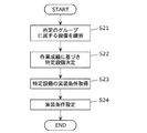
まず、識別部13が、生産システム1内の複数の部品実装機の中から、所定のグループに属するグループ内設備を識別する(S21)。具体的には、各部品実装機から送信される識別情報に基づき、自設備と同じグループに属する部品実装機を識別する。
First, the identifying
決定部16は、生産作業に関連する成績が所定の基準を満たす部品実装機である特定設備を決定する(S22)。具体的には、収集部15により収集された作業成績情報に基づき、最上位の成績の部品実装機を特定設備として決定する。
The
取得部17は、決定部16により決定された特定設備から実装条件を取得する(S23)。例えば、部品Aの吸着率が最も上位である特定設備からは、部品Aの吸着率に関連する実装条件を取得する。
The
取得部17により取得された実装条件は、通信部12により設定部20に通知され、設定部20により、その実装条件が設定される(S24)。
The mounting condition acquired by the acquiring
各部品実装機が上述の動作(S21〜S24)を行うことにより、各部品実装機は、自設備の属性に応じたグループ内で最適な実装条件を見つけることができ、さらに取得することができる。各部品実装機は取得した実装条件の下で部品の基板への実装を行うことにより、部品の吸着率や、部品の基板への装着率等が向上し、生産性が向上する。 When each component mounter performs the above-described operation (S21 to S24), each component mounter can find and further acquire the optimum mounting condition within the group according to the attribute of the own equipment. . Each component mounting machine mounts a component on a substrate under the acquired mounting conditions, thereby improving the component adsorption rate, the component mounting rate, and the like, thereby improving productivity.
なお、特定設備から取得した実装条件を設定した場合であっても、期待通りの成績を得ることができない場合も考えられる。 Even when the mounting conditions acquired from the specific equipment are set, there may be a case where the expected results cannot be obtained.
例えば、ある部品実装機が自設備と同じ機種である特定設備から実装条件を取得した場合を想定する。この場合、当該部品実装機と当該特定設備とに同一の実装条件が設定されている場合であっても、これら設備のもともとの個体差またはそれぞれの構成要素の配置された位置の誤差等により全くの同一の動作を行うとは限らない。 For example, assume a case where a component mounting machine acquires mounting conditions from a specific facility that is the same model as its own facility. In this case, even if the same mounting conditions are set for the component mounting machine and the specific equipment, it is completely different due to the original individual difference of these equipment or the error of the position where each component is arranged. The same operation is not always performed.
そこで、各部品実装機において実装条件の設定(S24)の後に、当該実装条件に関連する作業成績が向上しているか否かを確認してもよい。 Therefore, after setting the mounting conditions in each component mounter (S24), it may be confirmed whether or not the work results related to the mounting conditions are improved.
図7は、図6に示すフローに作業成績が向上したか否かを確認する動作を加えた場合のフローの一例を示す図である。 FIG. 7 is a diagram illustrating an example of a flow in the case where an operation for confirming whether or not work performance has been improved is added to the flow illustrated in FIG. 6.
図7に示すように、特定設備から取得した実装条件を設定(S24)した後に、その実装条件の下で部品実装基板の生産を試行する(S25)。試行の結果、作業成績が試行前の成績より向上したか否かを確認する(S26)。 As shown in FIG. 7, after setting the mounting conditions acquired from the specific equipment (S24), production of a component mounting board is tried under the mounting conditions (S25). As a result of the trial, it is confirmed whether or not the work result is improved from the result before the trial (S26).
例えば、部品実装機10が部品の吸着率が最も高い設備を特定設備と決定し、その特定設備から部品の吸着率に関連する実装条件である使用ノズルを特定する情報等を取得した場合を想定する。
For example, it is assumed that the
この場合、部品実装機10は、当該実装条件に示されるノズルに変更等する。つまり、当該実装条件を自設備に設定する(S24)。さらに、例えば、所定の個数の部品を実際に基板に実装する(S25)。これにより、当該実装条件の設定後の部品の吸着率を算出し、算出した吸着率が以前より向上しているか否かを確認する(S26)。
In this case, the
なお、これら吸着率の算出は、エラー検出部24が行い、上記確認は決定部16が行う。
The adsorption rate is calculated by the
部品の吸着率が向上している場合(S26でYes)、実装条件の設定に係る動作を終了し、例えば、そのまま部品実装作業を続ける。 When the suction rate of the component is improved (Yes in S26), the operation related to the setting of the mounting condition is terminated, for example, the component mounting operation is continued as it is.
また、部品の吸着率が以前より向上していない場合(S26でNo)、直前に決定された特定設備以外の設備を新たに特定設備として決定する(S27)。 In addition, when the suction rate of the parts has not improved from the previous time (No in S26), a facility other than the specific facility determined immediately before is newly determined as the specific facility (S27).
例えば、自設備が属するグループ内で部品の吸着率が2番目に高い部品実装機を新たに特定設備と決定し、部品の吸着に関連する実装条件の取得(S23)から当該実装条件下での試行(S25)までを行う。 For example, a component mounting machine having the second highest component suction rate in the group to which the own facility belongs is newly determined as a specific facility, and the acquisition of mounting conditions related to component suction (S23) Up to trial (S25).
その後、部品の吸着率が以前より向上したことを確認する(S26でYes)まで、特定設備の決定のやり直し(S27)から成績向上の確認(S26)までの一連の動作を繰り返す。 Thereafter, a series of operations from re-determination of the specific equipment (S27) to confirmation of improvement in results (S26) is repeated until it is confirmed that the suction rate of the parts has been improved (Yes in S26).
なお、特定設備の決定のやり直し(S27)を繰り返し行う場合、複数の部品実装機の中から吸着率の高いものを優先的に選択し特定設備と決定する。さらに、自設備より部品の吸着率の高い部品実装機が当該グループ内に存在しなくなった場合、特定設備の決定のやり直しは行わず、最初に実装条件の設定(S24)を行う直前の実装条件に戻す。 In addition, when re-determination (S27) of specific equipment is performed repeatedly, a thing with a high adsorption rate is selected preferentially and determined as specific equipment from a plurality of component mounting machines. Further, when there is no component mounter having a higher component adsorption rate than the own facility in the group, the specific facility is not re-determined and the mounting condition immediately before the first mounting condition setting (S24) is performed. Return to.
このように、以前の作業成績よりも向上しているか否かを確認することで、特定設備から取得した実装条件の真の適否を判断することができる。 In this way, it is possible to determine the true suitability of the mounting condition acquired from the specific equipment by confirming whether or not it is improved from the previous work result.
ここで、図6および図7のフロー図に示すグループ内設備の識別(S21)は識別部13によって行われる。具体的には、この識別の際に参照する識別情報は個体コード等であり、LAN5を介して他の部品実装機に要求することにより集められる。
Here, the identification of the in-group equipment shown in the flowcharts of FIGS. 6 and 7 (S21) is performed by the
また、本実施の形態において、個体コード等の識別情報を含む信号を敵味方信号といい、各部品実装機は、敵味方信号の要求を受信すると、当該要求への応答として敵味方信号を送信する。 In this embodiment, a signal including identification information such as an individual code is referred to as an enemy ally signal. Upon receiving a request for an enemy ally signal, each component mounter transmits an enemy ally signal as a response to the request. To do.
図8は、実施の形態1における敵味方信号のデータ構成の概要を示す図である。
図8に示すように、敵味方信号は、メーカコード、カテゴリコード、および個体コードを含んでいる。敵味方信号に含まれるこれらコードのそれぞれ、またはこれらの結合は、本発明の実装条件決定方法における識別情報を構成する。
FIG. 8 is a diagram illustrating an outline of a data configuration of an enemy ally signal in the first embodiment.
As shown in FIG. 8, the enemy / ally signal includes a manufacturer code, a category code, and an individual code. Each of these codes included in the enemy friendly signal or a combination thereof constitutes identification information in the mounting condition determining method of the present invention.
また、図8に示す敵味方信号は、部品実装機であるM123−2から他の部品実装機へ送信される敵味方信号の例である。図8に示すように、この敵味方信号には、M123−2を製造したメーカであるA社のメーカコード“AAA”と、M123−2が属するカテゴリグループであるMグループのカテゴリコード“G−AM”と、個体コード“M123−2”とが含まれている。 Moreover, the enemy friend signal shown in FIG. 8 is an example of the enemy friend signal transmitted from M123-2 which is a component mounting machine to another component mounting machine. As shown in FIG. 8, in this enemy and ally signal, the manufacturer code “AAA” of the company A that manufactured M123-2 and the category code “G−” of the group M to which the category group M123-2 belongs are included. AM ”and the individual code“ M123-2 ”are included.
個体コードは、上述のように機種コードと設備番号とから構成されており、機種コードは機種を示す情報である。つまり、個体コードに“M123”が含まれる部品実装機は、その機種が“M123”であることを意味する。なお、設備番号は、同一機種内で一意な数字である。 The individual code is composed of the model code and the equipment number as described above, and the model code is information indicating the model. That is, the component mounter including “M123” in the individual code means that the model is “M123”. The equipment number is a unique number within the same model.
M123−1が、図8に示す敵味方信号を受信した場合、メーカコードおよびカテゴリコードから、M123−2は、自設備と同一のメーカグループおよびカテゴリグループに属する部品実装機であると識別できる(図2参照)。また、個体コードに含まれる機種コードから、自設備と同一の機種グループに属すると識別できる。 When M123-1 receives the enemy friendly signal shown in FIG. 8, it can be identified from the manufacturer code and category code that M123-2 is a component mounter belonging to the same manufacturer group and category group as the own equipment ( (See FIG. 2). Further, it can be identified from the model code included in the individual code that it belongs to the same model group as the own equipment.
図9は、実施の形態1における部品実装機10が行う敵味方信号の要求および受信を模式的に表す図である。部品実装機10であるM123−1は、生産システム1内のM123−2等の全ての部品実装機へ敵味方信号の要求を送信することで、全ての部品実装機から敵味方信号を受信することができる。他の部品実装機も同様に、全ての部品実装機から敵味方信号を受信することができる。
FIG. 9 is a diagram schematically illustrating a request and reception of an enemy friend signal performed by the
なお、各部品実装機は、敵味方信号の要求を受信した場合、通信部12が、自設備の機種コード等を含む敵味方信号を要求への応答として送信する。これら自設備についての機種コード等の情報は、通信部12が保持しておいてもよく、実装条件決定装置11以外の部品実装機10の構成部、例えば、条件記憶部21が保持しておいてもよい。実装条件決定装置11以外の構成部が機種コード等の情報を保持する場合、通信部12が当該情報を当該構成部から受け取って敵味方信号を生成し、要求への応答として送信すればよい。
When each component mounter receives a request for an enemy ally signal, the
図10は、実施の形態1における部品実装機10が他の部品実装機を識別する際の動作の流れを示すフロー図である。つまり、図6および図7のフロー図に示す、自設備と同じグループに属するグループ内設備を識別する動作(S21)を詳細に説明するフロー図である。
FIG. 10 is a flowchart showing an operation flow when the
図10を用いて、部品実装機10を含む生産システム1の各部品実装機が行う他の部品実装機を識別する際の動作の流れを説明する。
With reference to FIG. 10, the flow of operations when identifying other component mounters performed by each component mounter of the
各部品実装機が有する通信部12からLAN5に接続された全部品実装機に敵味方信号の要求がブロードキャストされる(S31)。通信部12は要求に応じて送信される敵味方信号を受信する(S32)。
A request for an enemy friend signal is broadcast from the
識別部13は、通信部12により受信された敵味方信号から、当該敵味方信号の送信元の部品実装機を示す個体コードを読み出す。さらに、個体コードに含まれる機種コード、およびカテゴリコードから、その個体コードの送信元である部品実装機が、(1)自設備と同じ機種グループに属する設備であるか、および(2)自設備と同じカテゴリグループに属する設備であるかを識別する(S33)。
The
識別部13は、上記識別の結果から、自設備と同じ機種グループに属する部品実装機の個体コードを記録したテーブルと、自設備と同じカテゴリグループに属する部品実装機の個体コードを記録したテーブルとを作成する(S34)。作成された各テーブルはグループ記憶部14に記憶される。
Based on the identification result, the
生産システム1内の各部品実装機は、上記一連の動作により、他の全ての部品実装機について自設備と同じグループに属するか否かの識別を行うことができる。
Each component mounter in the
なお、敵味方信号を送受信する機能を有しない部品実装機が存在する場合も考えられる。例えば、A社の部品実装機のみが敵味方信号を送受信する機能を有している場合は、A社グループに属する部品実装機のみが上記の識別等の処理の対象および主体となることができる。つまり、A社グループに属する部品実装機のみが最適な実装条件に統一されることとなる。 In addition, there may be a case where there is a component mounting machine that does not have a function of transmitting and receiving an enemy friend signal. For example, when only the component mounting machine of company A has a function of transmitting and receiving an enemy friend signal, only the component mounting machine belonging to the company A group can be the target and subject of the above-described identification and the like. . That is, only the component mounters belonging to the A company group are unified to the optimum mounting conditions.
また、例えば、A社の部品実装機およびB社の部品実装機ともに敵味方信号を送受信する機能を有している場合であっても、各部品実装機は、他メーカの部品実装機からの作業成績情報および実装条件の要求に応じなくてもよい。 In addition, for example, even if the component mounting machine of Company A and the component mounting machine of Company B both have a function of transmitting and receiving an enemy friendly signal, each component mounting machine can receive a signal from another manufacturer's component mounting machine. It is not necessary to meet the requirements for work performance information and mounting conditions.
つまり、部品実装機等の設備において、例えば実装条件が設備の製造メーカ独自のノウハウに関わるような場合、他メーカの設備への情報提供を行わなくてもよい。このような場合であっても、それぞれのメーカグループに属する各設備の実装条件は、それぞれのメーカグループ内で最適な実装条件に統一され、生産性が向上される。 That is, in equipment such as a component mounter, for example, when the mounting conditions relate to the know-how unique to the manufacturer of the equipment, it is not necessary to provide information to equipment of other manufacturers. Even in such a case, the mounting conditions of each facility belonging to each manufacturer group are unified to the optimal mounting conditions in each manufacturer group, and productivity is improved.
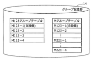
図11は、実施の形態1における部品実装機10が備えるグループ記憶部14に記憶されるグループテーブルの例を示す図である。
FIG. 11 is a diagram illustrating an example of a group table stored in the
図11に示す“M123グループテーブル”とは、機種コードが“M123”である部品実装機の個体コードが記録されたテーブルである。つまり、自設備と同一の機種グループに属する部品実装機を特定するテーブルである。 The “M123 group table” shown in FIG. 11 is a table in which the individual code of the component mounter whose model code is “M123” is recorded. That is, it is a table for specifying a component mounter belonging to the same model group as the own equipment.
また、“Mグループテーブル”とは、カテゴリコードが“G−AM”である部品実装機の個体コードが記録されたテーブルである。つまり、自設備と同一のカテゴリグループに属する部品実装機を特定するテーブルである。 The “M group table” is a table in which individual codes of component mounters having a category code “G-AM” are recorded. That is, it is a table that identifies a component mounter that belongs to the same category group as its own equipment.
部品実装機10であるM123−1の収集部15は、これらグループテーブルを参照することで、自設備と同じカテゴリグループであるMグループに属する他の部品実装機、および、自設備と同じ機種グループであるM123グループに属する他の部品実装機から作業成績情報を収集することができる。
The
図12は、実施の形態1における部品実装機10が特定設備から実装条件を取得し、その実装条件を自設備に設定する際の動作の流れを示すフロー図である。つまり、図6のフロー図に示す、特定設備の決定(S22)のための動作から、実装条件の設定(S24)までを詳細に説明するフロー図である。
FIG. 12 is a flowchart showing an operation flow when the
図12を用いて、部品実装機10を含む生産システム1の各部品実装機が行う実装条件の取得およびその実装条件の設定に係る動作の流れを説明する。
With reference to FIG. 12, the flow of operations related to acquisition of mounting conditions and setting of the mounting conditions performed by each component mounting machine of the
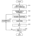
各部品実装機において、所定の指示、例えばオペレータからの指示により部品実装基板の生産が開始される(S41)。生産の開始後、エラー検出部24は、検出したエラーの種類等に基づき自設備における作業成績を集計する(S42)。この集計により生成される作業成績情報は、成績情報記憶部25に記憶される。
In each component mounting machine, the production of the component mounting board is started by a predetermined instruction, for example, an instruction from the operator (S41). After the start of production, the
収集部15は、自設備のものも含め、グループ内設備から作業成績情報を収集する(S43)。具体的には、M123−1であれば、グループ記憶部14に記憶されているM123グループテーブルおよびMグループテーブルの少なくとも一方を参照し、参照するグループテーブルに記録されている個体コードを宛先として、作業成績情報の要求を送信する。
The
どのグループテーブルを参照するかについては、例えば、オペレータの明示の指示に従ってもよく、また、参照するたびに変えてもよい。 Which group table is referred to may be, for example, in accordance with an explicit instruction from the operator, or may be changed each time it is referred to.
また、上述のように、収集の対象とするグループに応じて収集する作業成績情報の種類が選択される。 Further, as described above, the type of work result information to be collected is selected according to the group to be collected.
上記作業成績情報の要求には、送信すべき作業成績情報の種類を指定する情報が含まれている。例えば、“部品Aについての吸着率”を指定する情報が含まれている。この要求を受信したグループ内設備は、当該要求への応答として、例えば、“部品Aについての吸着率:98%”という情報を要求元の部品実装機へ送信する。 The request for work performance information includes information specifying the type of work performance information to be transmitted. For example, information specifying “suction rate for part A” is included. The equipment in the group that has received this request transmits, for example, information “adsorption rate for component A: 98%” to the requesting component mounter as a response to the request.
このような要求および応答により、自設備も含め、グループ内設備の作業成績情報が収集される。収集される作業成績情報の例としては、部品ごとの吸着率、装着率、認識エラー率、装着精度などである。 By such a request and response, work performance information of the equipment in the group including the own equipment is collected. Examples of the collected work result information include a suction rate, a mounting rate, a recognition error rate, and a mounting accuracy for each part.
図13は、収集部15により収集された作業成績情報の例を示す図である。なお、図13は、M123−1の収集部15が上記収集を行った結果、決定部16に保持される作業成績情報の例を示している。
FIG. 13 is a diagram illustrating an example of work result information collected by the
図13に示すように、M123−1と同じ機種グループに属する各部品実装機から、部品Aについての吸着率等の作業成績情報が収集され、どの部品実装機が最上位の成績であるかを判断することができる。図の例では、部品Aについての吸着率では、M123−3が“99%”であり、最上位の成績である。 As shown in FIG. 13, work result information such as the suction rate for the component A is collected from each component mounter belonging to the same model group as the M123-1, and which component mounter has the highest grade is shown. Judgment can be made. In the example of the drawing, M123-3 is “99%” in the suction rate for the part A, which is the highest grade.
同様に、部品Aについての装着率や、部品Bについての吸着率などの、その他の部品についてのその他の作業成績情報も収集され、決定部16により、それぞれについて最上位の成績を記録した部品実装機が特定設備として決定される(S44)。
Similarly, other work performance information about other parts, such as the mounting rate for part A and the suction rate for part B, is also collected, and the component mounting with the highest grade recorded for each by the
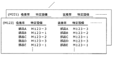
図14は、決定部16により決定された特定設備群の例を示す図である。
図14に示すように、吸着率、装着率等の作業成績情報の種類ごとに、部品ごとの特定設備が決定されている。
FIG. 14 is a diagram illustrating an example of the specific equipment group determined by the
As shown in FIG. 14, specific equipment for each part is determined for each type of work result information such as an adsorption rate and a mounting rate.
例えば、部品Aについての吸着率ではM123−3が特定設備であり、部品Bについての吸着率ではM123−1が特定設備である。また、部品Aについての装着率ではM123−3が特定設備であり、部品Bについての装着率ではM123−2が特定設備である。 For example, in the adsorption rate for the component A, M123-3 is a specific facility, and in the adsorption rate for the component B, M123-1 is a specific facility. Further, in the mounting rate for the component A, M123-3 is a specific facility, and in the mounting rate for the component B, M123-2 is a specific facility.
なお、特定設備の決定は、M123−2等の他の部品実装機でも行われ、例えば、M123グループに属する各部品実装機の決定部16は、図14に示す特定設備の決定結果と同じ決定結果を得ることとなる。
The determination of the specific equipment is also performed by other component mounters such as M123-2. For example, the
取得部17は、このように決定された特定設備から実装条件を取得する(S45)。具体的には、実装条件の要求に対する応答として特定設備から送信される実装条件を取得する。また、実装条件としてどのような情報が取得されるかについては、図15および図16を用いて後述する。
The
取得部17により取得された実装条件は、通信部12により設定部20へ通知され、設定部20により機構制御部22に設定される(S46)。また、その実装条件は条件記憶部21に記憶される。機構部23は、機構制御部22に設定された実装条件の下で部品の基板への実装を行う。
The mounting condition acquired by the
その後、生産が継続中は(S47でNo)、上記動作が繰り返され、オペレータの指示等により生産が終了すると(S47でYes)、実装条件の設定に係る上記一連の処理も終了する。 Thereafter, while the production is continuing (No in S47), the above operation is repeated, and when the production is terminated by an operator's instruction or the like (Yes in S47), the series of processes related to the setting of the mounting conditions is also terminated.
なお、グループ内設備からの作業成績情報の収集(S43)から、実装条件の設定(S46)までは、所定のタイミングで自発的に行われる。例えば、所定の期間の経過ごとに行われる。この所定のタイミングについての情報は、例えば生産システム1の管理者により設定される情報であり収集部15に保持されている。
Note that the collection of work result information from the equipment in the group (S43) to the setting of the mounting conditions (S46) are performed spontaneously at a predetermined timing. For example, it is performed every elapse of a predetermined period. The information about the predetermined timing is information set by the administrator of the
収集部15は内部に時計またはタイマを有しており、この情報に示されるタイミングで作業成績情報の収集を開始する。また、収集部15により作業成績情報が収集される(S43)ことを契機とし、以降、実装条件の設定(S46)まで行われる。
The
また、ある作業成績情報について、自設備が最上位であった場合、その作業成績情報に関連する実装条件は変更する必要がないため、実装条件の取得(S45)および設定(S46)の動作は行わない。 In addition, when the own equipment is at the highest level for certain work performance information, it is not necessary to change the mounting conditions related to the work performance information, so the operation of acquiring (S45) and setting (S46) the mounting conditions is Not performed.
ここで、例えば部品Aについての吸着率とは、上述のように、部品Aの吸着という生産作業に関連する成績を示す情報である。また、このような成績の良し悪しは、どのような実装条件の下で当該生産作業が行われたかに依存する。 Here, for example, the adsorption rate for the part A is information indicating a result related to the production operation of adsorption of the part A as described above. The quality of such results depends on the mounting conditions under which the production work is performed.
従って、例えばM123−1が、部品Aの吸着率について最も良い成績を残したM123−3から、部品Aの吸着に関連する実装条件を取得することにより、M123−1における部品Aの吸着率を向上させることができるわけである。 Therefore, for example, M123-1 obtains the mounting condition related to the suction of the component A from the M123-3 that has the best results for the suction rate of the component A, so that the suction rate of the component A in the M123-1 is obtained. It can be improved.
つまり、吸着率等の作業成績情報の種類と実装条件とは、生産作業の内容が何であるかを介して関連付けられるものである。 That is, the type of work result information such as the suction rate and the mounting condition are associated with each other through what the content of the production work is.
図15は、吸着率等の作業成績情報の種類と実装条件との関連付けの例を示す図である。 FIG. 15 is a diagram illustrating an example of the association between the type of work result information such as the suction rate and the mounting conditions.
図15に示すように、例えば、吸着率に関連する実装条件は、ノズル、吸着動作パターン、および吸着補正値の3つの項目の組である。具体的には、それぞれ、ノズルを特定するノズル番号、吸着動作パターンを特定するパターン番号、ノズルの吸着位置を補正するX軸方向およびY軸方向(図3参照)の数値が実装条件として特定設備以外の部品実装機に取得され設定される。 As shown in FIG. 15, for example, the mounting condition related to the suction rate is a set of three items of a nozzle, a suction operation pattern, and a suction correction value. Specifically, the nozzle number for specifying the nozzle, the pattern number for specifying the suction operation pattern, and the numerical values in the X-axis direction and the Y-axis direction (see FIG. 3) for correcting the suction position of the nozzle are specified equipment as the mounting conditions. Acquired and set by other component mounters.
例えば、M123−1が、特定設備であるM123−3から部品Aについての上記3項目からなる実装条件を取得し設定することで、M123−1における部品Aの吸着率が向上することになる。装着率等の他の作業成績情報も、それぞれ図15に示すように実装条件と関連付けられる。 For example, when the M123-1 acquires and sets the mounting conditions including the above three items for the part A from the specific equipment M123-3, the adsorption rate of the part A in the M123-1 is improved. Other work result information such as the mounting rate is also associated with the mounting condition as shown in FIG.
このような、特定設備からの実装条件の取得は、当該特定設備と同じグループに属する各部品実装機において、上述のように所定のタイミングで自発的に行われ、これにより、各部品実装機における吸着率等が向上し、結果として生産性が向上される。 Such acquisition of mounting conditions from a specific facility is performed spontaneously at a predetermined timing as described above in each component mounter belonging to the same group as the specific facility. The adsorption rate and the like are improved, and as a result, productivity is improved.
図16は、特定設備から各部品実装機に取得される実装条件の例を示す図である。
図16の例では、特定設備であるM123−3から、部品Aの吸着率に関連する実装条件がM123グループに属する他の部品実装機に取得される様子を示している。
FIG. 16 is a diagram illustrating an example of mounting conditions acquired from a specific facility to each component mounter.
In the example of FIG. 16, the mounting condition related to the suction rate of the component A is acquired by the other component mounting machine belonging to the M123 group from the specific facility M123-3.
図16に示す実装条件の例は、ノズルはノズル番号“2”であり、吸着動作パターンはパターン番号“3”であり、吸着補正値は“(0.002、0.001)”(単位はmm)であることを示している。これら番号および値が、各部品実装機で実装条件として設定される。 In the example of the mounting condition shown in FIG. 16, the nozzle is the nozzle number “2”, the suction operation pattern is the pattern number “3”, and the suction correction value is “(0.002, 0.001)” (the unit is mm). These numbers and values are set as mounting conditions in each component mounting machine.
また、各部品実装機は、その他、部品Bの吸着率に関連する実装条件、部品Aの装着率に関連する実装条件、部品Cの認識エラー率に関連する実装条件など、複数の部品と複数の作業成績情報の種類との組み合わせに応じた実装条件を、それぞれの特定設備から取得する。つまり、最も良い実装条件を取得し設定する。 In addition, each component mounting machine includes a plurality of components such as a mounting condition related to the adsorption rate of the component B, a mounting condition related to the mounting rate of the component A, and a mounting condition related to the recognition error rate of the component C. Implementation conditions corresponding to the type of work performance information are acquired from each specific facility. In other words, the best mounting conditions are acquired and set.
例えば、各特定設備が、図14に示すように決定されている場合、M123−3の部品Aの吸着率に関連する実装条件が、M123グループに属する他の部品実装機に設定される。また、M123−1の部品Bの吸着率に関連する実装条件が、M123グループに属する他の部品実装機に設定される。 For example, when each specific facility is determined as shown in FIG. 14, the mounting condition related to the suction rate of the component A of M123-3 is set in another component mounting machine belonging to the M123 group. Further, the mounting condition related to the suction rate of the component B of M123-1 is set in another component mounting machine belonging to the M123 group.
装着率や認識エラー率についても、同様に、最上位の成績に対応する実装条件が、M123グループに属する全部品実装機に設定されることになる。 Similarly, with respect to the mounting rate and the recognition error rate, the mounting conditions corresponding to the highest grade are set for all the component mounting machines belonging to the M123 group.
このように、本実施の形態の部品実装機10は、自設備と同じグループに属する部品実装機から作業成績情報を収集し、最上位の成績の部品実装機を特定設備として決定する。更に、特定設備から当該作業成績情報に関連する実装条件を取得し、自設備に設定することができる。
As described above, the
また、この作業成績情報の収集、および実装条件の取得の対象となる部品実装機のグループは、機種等の属性に応じて分けられている。つまり、あるグループに属する各部品実装機は、機器構成等の共通性を有している。そのため、各部品実装機は、自設備が属するグループ内で決定される特定設備から取得する実装条件を、そのまま自設備に設定することができ、かつ、自設備の生産性を向上させることができる。 In addition, the group of component mounters for which the collection of work performance information and the acquisition of the mounting conditions are divided according to attributes such as the model. That is, each component mounter belonging to a certain group has commonality such as device configuration. Therefore, each component mounting machine can set the mounting conditions acquired from the specific equipment determined within the group to which the equipment belongs to the equipment itself, and can improve the productivity of the equipment. .
また、他の部品実装機も、部品実装機10と同じく実装条件決定装置11を備えており、各部品実装機においても、自設備が属するグループ内において最も良い実装条件を取得し設定することができる。言い換えると、各部品実装機は、自律的に実装条件の最適化を行うことができる。
Further, other component mounting machines also include a mounting
結果として、生産システム1に属する全ての部品実装機は、それぞれのグループ内において最も生産性を向上させる実装条件が設定されることになり、各部品実装機の生産性はもとより、生産システム1全体の生産性が向上される。
As a result, all the component mounting machines that belong to the
なお、本実施の形態において、実装条件を決定する際の処理内容や実装条件決定装置11の構成等は、それぞれ上述の記載内容に限定されることはない。そこで、以下に、本実施の形態の変形例について説明する。
In the present embodiment, the processing contents when determining the mounting conditions, the configuration of the mounting
(実施の形態1の変形例1)
実施の形態1の変形例1として、実装条件の決定手法の変形例について述べる。
(
As a first modification of the first embodiment, a modification of the mounting condition determination method will be described.
図15に示すように、吸着率および装着率は、ともに実装条件の項目としてノズルを有している。従って、例えば、部品Aについて、吸着率が最も良いノズルはノズル番号“2”のノズルであるが、装着率が最も良いノズルはノズル番号“3”のノズルであるという場合も考えられる。 As shown in FIG. 15, both the suction rate and the mounting rate have nozzles as mounting condition items. Therefore, for example, for component A, the nozzle with the highest suction rate is the nozzle with nozzle number “2”, but the nozzle with the highest mounting rate is the nozzle with nozzle number “3”.
このように、最上位の成績に対応する実装条件同士が相反する場合、上記例でいうと、部品Aの吸着および装着に使用するノズルを多数決でどちらか一方に決定してもよい。例えば、上記状況にあるグループ内で部品Aの吸着率が所定の率、例えば97%以上であり、かつ上位5位以内の部品実装機が部品Aの吸着および装着に使用しているノズルを調べる。また、部品Aの装着率に関しても同様に調べる。 As described above, when the mounting conditions corresponding to the highest grades conflict with each other, in the above example, the nozzle used for sucking and mounting the component A may be determined by majority vote. For example, in the group in the above situation, the suction rate of the component A is a predetermined rate, for example, 97% or more, and the nozzles used by the top five component mounters for the suction and mounting of the component A are checked. . Further, the mounting rate of the part A is similarly examined.
このようにして調べられたノズルの中で、ノズル番号“2”のノズルと、ノズル番号“3”のノズルのいずれがより多く使用されているかで決定してもよい。 Of the nozzles examined in this way, it may be determined which of the nozzle with the nozzle number “2” and the nozzle with the nozzle number “3” is used more frequently.
このように、多数決で決定する場合、実装条件として、例えば部品Aについての吸着率が最上位であるノズル番号“2”のノズルではなく、ノズル番号“3”のノズルが選択されることがあり得る。しかし、上述のように、吸着率および装着率のそれぞれについて所定の率以上であるという条件を加えることにより、一定水準の吸着率および装着率は担保される。 As described above, when the majority decision is made, for example, the nozzle with the nozzle number “3” may be selected as the mounting condition instead of the nozzle with the nozzle number “2” having the highest suction rate for the component A. obtain. However, as described above, by adding the condition that the adsorption rate and the mounting rate are equal to or higher than a predetermined rate, a certain level of the adsorption rate and the mounting rate is secured.
また、多数決以外の方法でもよい。例えば、ノズルについては吸着率を優先するといった決定方法でもよい。また、例えば、ノズル番号“2”のノズルの吸着率と装着率との積と、ノズル番号“3”のノズルの吸着率と装着率との積とを比較し、大きい方を採用するとしてもよい。これらの場合であっても、吸着率および装着率のそれぞれについて所定の率以上という制限を設けることで、一定水準の吸着率および装着率は担保される。 Also, a method other than majority vote may be used. For example, a determination method that prioritizes the suction rate for the nozzles may be used. Further, for example, the product of the suction rate and the mounting rate of the nozzle with the nozzle number “2” is compared with the product of the suction rate and the mounting rate of the nozzle with the nozzle number “3”, and the larger one is adopted. Good. Even in these cases, a certain level of the adsorption rate and the mounting rate can be ensured by providing a restriction of a predetermined rate or more for each of the adsorption rate and the mounting rate.
また、この所定の率は、部品実装機ごとに異なる値が設定されてもよい。例えば、M123−1における現状の部品Aの吸着率を超える値がそれぞれ所定の率としてM123−1に設定されていれば、M123−1における部品Aの吸着率を少なくとも現状よりも向上させることができる。 Also, this predetermined rate may be set to a different value for each component mounter. For example, if a value exceeding the current adsorption rate of the component A in M123-1 is set as a predetermined rate in M123-1, the adsorption rate of the component A in M123-1 can be improved at least from the current value. it can.
従って、他の部品実装機についてもそれぞれの現状の吸着率等の作業成績に応じた値が所定の率として設定されていれば、少なくとも現状よりも生産性を向上させることができる。 Therefore, for other component mounting machines, if a value corresponding to the work performance such as the current suction rate is set as a predetermined rate, productivity can be improved at least as compared with the current level.
(実施の形態1の変形例2)
実施の形態1の変形例2として、実装条件決定装置11における識別情報の取得方法の変形例について述べる。
(
As a second modification of the first embodiment, a modification of the identification information acquisition method in the mounting
実装条件決定装置11は、各部品実装機の個体コード等の識別情報をLAN5経由で受信するとした。しかしながら、他の手段により取得してもよい。例えば、生産システム1において設備の入れ換えや、グループ分けの変更があまりないような場合、CD−ROM等の記録媒体に各部品実装機が敵味方信号で送信する個体コード等の識別情報を記録しておき、実装条件決定装置11がそのCD−ROM等の記録媒体を読み込むことにより、これらの個体コード等を取得してもよい。
The mounting
また、同様に、各部品実装機の作業成績情報も、LAN5経由で収集する以外の手段により取得してもよい。例えば、1日に一度、各部品実装機の作業成績情報をまとめてCD−ROM等の記録媒体に記憶させ、そのCD−ROM等から実装条件決定装置11が読み出して特定設備の決定を行ってもよい。
Similarly, the work result information of each component mounting machine may be acquired by means other than collecting via the
このようにすることで、例えば、LAN5に対する通信負荷を軽減することができる。
By doing so, for example, the communication load on the
(実施の形態1の変形例3)
実施の形態1の変形例3として、各部品実装機が取得する実装条件の基本単位を部品以外のものにする場合について述べる。
(
As a third modification of the first embodiment, a case will be described in which the basic unit of the mounting condition acquired by each component mounter is other than a component.
本実施の形態の説明において、各部品実装機が他の部品実装機から取得し設定する実装条件は、部品を基本単位とし、部品ごとの吸着率等を向上させる実装条件を取得し設定するとした。 In the description of the present embodiment, the mounting conditions that each component mounter obtains and sets from other component mounters are assumed to acquire and set the mount conditions that improve the suction rate and the like for each component with the component as a basic unit. .
しかしながら、部品以外を基本単位としてもよい。例えば、ノズルを基本単位とし、各部品実装機において、使用ノズルごとに認識エラー率を集計する。さらに、他の部品実装機におけるノズルごとの認識エラー率を収集し、ノズルごとに、最も認識エラー率の低い部品実装機を特定設備と決定する。 However, units other than parts may be used as basic units. For example, using the nozzle as a basic unit, the recognition error rates are tabulated for each used nozzle in each component mounting machine. Furthermore, the recognition error rate for each nozzle in another component mounting machine is collected, and the component mounting machine having the lowest recognition error rate is determined as the specific equipment for each nozzle.
これにより、各部品実装機は、ノズルごとの認識エラー率を改善する実装条件を特定設備から取得し自設備に設定することができ、結果として生産性を向上させることができる。 Thereby, each component mounting machine can acquire the mounting condition which improves the recognition error rate for every nozzle from a specific installation, and can set it to an own installation, and can improve productivity as a result.
例えば、M123−1が、ノズル番号1のノズルを使用していると想定する。この場合、M123−1は、ノズル番号1のノズルを使用している他の部品実装機の中で、認識エラー率が最も低い部品実装機から、認識エラー率に関連する実装条件として、ノズル番号1のノズルを使用する際のライトの光量等を取得する。
For example, it is assumed that M123-1 uses the nozzle of
これにより、M123−1のノズル番号1のノズルを使用する際の認識エラー率を低下させることができる。
Thereby, the recognition error rate at the time of using the nozzle of the
同様に、例えば、カメラを複数有する部品実装機のグループにおいて、各部品実装機は、カメラごとの認識エラー率を収集し特定設備を決定してもよい。これにより、使用するカメラごとに、最も認識エラー率を低くするライトの光量等の実装条件を設定することができ、生産性を向上させることができる。 Similarly, for example, in a group of component mounters having a plurality of cameras, each component mounter may collect a recognition error rate for each camera and determine a specific facility. Thereby, for each camera to be used, it is possible to set mounting conditions such as the light quantity of light that minimizes the recognition error rate, thereby improving productivity.
(実施の形態1の変形例4)
実施の形態1の変形例4として、各部品実装機が取得する実装条件の内容の変形例について述べる。
(
As a fourth modification of the first embodiment, a modification of the contents of the mounting conditions acquired by each component mounter will be described.
本実施の形態において、作業成績情報の種類と実装条件との関連付けは、図15に示す組み合わせであるとした。しかしながら図15に示す以外の組み合わせであってもよい。例えば、ある部品についての吸着率に関連する実装条件は、図15に示す例では、ノズル、吸着動作パターン、および吸着補正値の3項目の情報から構成されている。しかしながら、例えば、部品の吸着の成否がほとんどノズルの選択に依存する場合、実装条件の項目が、“ノズル”のみであってもよい。他の種類の作業成績情報についても同様である。 In the present embodiment, the association between the type of work performance information and the mounting conditions is the combination shown in FIG. However, combinations other than those shown in FIG. For example, in the example shown in FIG. 15, the mounting condition related to the suction rate for a certain component is configured from information of three items, that is, a nozzle, a suction operation pattern, and a suction correction value. However, for example, when the success or failure of component adsorption depends mostly on the selection of the nozzle, the item of mounting conditions may be only “nozzle”. The same applies to other types of work performance information.
つまり、各部品実装機は、生産性を向上させ得る少なくとも1種類の情報を実装条件として取得できればよい。このような情報としては、上述のように、部品の吸着率が最も良いノズルのノズル番号や移動速度、装着精度が最も良い部品実装機におけるNCデータ等がある。 That is, each component mounting machine only needs to acquire at least one type of information that can improve productivity as a mounting condition. Such information includes, as described above, the nozzle number and moving speed of the nozzle having the best component adsorption rate, NC data in the component mounting machine having the best mounting accuracy, and the like.
各部品実装機は、このような情報のうち、少なくとも1種類の情報を実装条件として取得し、その情報に示される特定の値等に設定または変更することで、当該実装条件に応じた生産作業の効率性の向上が可能となる。 Each component mounter obtains at least one type of information as such mounting information as a mounting condition, and sets or changes it to a specific value or the like indicated in the information, thereby producing work according to the mounting condition. It is possible to improve the efficiency.
(実施の形態1の変形例5)
実施の形態1の変形例5として、各部品実装機が収集する作業成績情報の種類の選択方法の変形例について述べる。
(
As a fifth modification of the first embodiment, a modification of the method for selecting the type of work result information collected by each component mounter will be described.
本実施の形態において、収集部15がグループ内設備から収集する作業成績情報の種類は、自設備が属するどのグループを作業成績情報の収集の対象とするかにより選択されるとした。しかしながら、逆に、収集部15が収集する作業成績情報の種類に応じて、収集の対象とするグループを選択してもよい。
In the present embodiment, the type of work result information collected by the
例えば、収集部15が作業成績情報として認識エラー率を収集する場合を想定する。この場合、認識エラー率に関係する機器はカメラ、ライト等である。従って、同一のカメラ、ライト等を共通して備えている部品実装機のグループを作業成績情報の収集の対象としてもよい。
For example, it is assumed that the
つまり、収集する作業成績情報の種類の選択と、収集の対象とするグループの選択は、いずれが主となってもよい。どちらの場合においても、本実施の形態の部品実装機10は、自設備の生産性を向上させることのできる実装条件を、他の部品実装機から取得することができる。
In other words, either the selection of the type of work performance information to be collected or the selection of the group to be collected may be the main. In either case, the
(実施の形態1の変形例6)
実施の形態1の変形例6として、各部品実装機が実装条件の取得の際に1つの部品実装機を比較の対象とする場合について述べる。
(Modification 6 of Embodiment 1)
As a sixth modification of the first embodiment, a case will be described in which each component mounter uses one component mounter as a comparison target when acquiring mounting conditions.
上述の説明において、M123グループに属する各部品実装機が、他の複数の部品実装機から吸着率等を収集し、特定設備を決定する場合について説明した。しかしながら、各部品実装機において吸着率等を向上させるためには、少なくとも1つの他の部品実装機から吸着率等の作業成績情報を収集すればよい。 In the above description, the case where each component mounter belonging to the M123 group collects the suction rate from a plurality of other component mounters and determines a specific facility has been described. However, in order to improve the suction rate and the like in each component mounting machine, it is only necessary to collect work result information such as the suction rate from at least one other component mounting machine.
例えば、図2に示すT121グループは、属する部品実装機は、T121−1と、T121−2だけである。この場合、T121−1は、T121−2から、例えば部品Aについての吸着率を収集し、自設備における当該吸着率と比較する。比較の結果、T121−2の吸着率の方が上位であれば、T121−2から、部品Aの吸着率に関連する実装条件を取得し自設備に設定する。これにより、T121−1における部品Aの吸着率を向上させることができる。 For example, in the T121 group shown in FIG. 2, only the component mounters T121-1 and T121-2 belong. In this case, T121-1 collects, for example, the suction rate for the part A from T121-2, and compares the collected suction rate with the own equipment. As a result of the comparison, if the suction rate of T121-2 is higher, the mounting condition related to the suction rate of component A is acquired from T121-2 and set in its own equipment. Thereby, the adsorption | suction rate of the components A in T121-1 can be improved.
また、逆に、T121−1の吸着率の方が上位であれば、つまり、自設備における成績の方が上位であれば、自設備の部品Aの吸着率に関連する実装条件を、T121−2に与えてもよい。これにより、T121−2における部品Aの吸着率を向上させることができる。 Conversely, if the suction rate of T121-1 is higher, that is, if the result in the own equipment is higher, the mounting condition related to the suction rate of the component A of the own equipment is set to T121-. 2 may be given. Thereby, the adsorption | suction rate of the components A in T121-2 can be improved.
なお、このように、他の1つの設備との比較により、自設備に設定する実装条件を決定する方法は、複数の設備と通信可能な状況においても実施可能であり、この場合は、結果的にはグループ内で最上位の成績に対応する実装条件が設定されることになる。 In addition, in this way, the method for determining the mounting conditions to be set in the own equipment by comparison with one other equipment can be implemented even in a situation where communication with a plurality of equipment is possible. In this case, as a result The implementation condition corresponding to the highest grade in the group will be set in.
図17は、他の1つの設備との比較により自設備に設定する実装条件を決定し取得する方法を複数の部品実装機が実施する様子を示す模式図である。 FIG. 17 is a schematic diagram showing a state in which a plurality of component mounters implement a method for determining and acquiring a mounting condition to be set for its own equipment by comparison with another equipment.
なお、図17において、M123−1、M123−2、およびM123−3のそれぞれの部品Aについての吸着率はM123−1、M123−2、M123−3の順に高くなると想定する。また、当該吸着率に関連する実装条件を、実装条件α、実装条件β、および実装条件γと想定する。 In FIG. 17, it is assumed that the suction rates for the parts A of M123-1, M123-2, and M123-3 increase in the order of M123-1, M123-2, and M123-3. Further, the mounting conditions related to the suction rate are assumed to be a mounting condition α, a mounting condition β, and a mounting condition γ.
つまり、M123−3の実装条件γが部品Aについての吸着率を最も高くする実装条件であり、実装条件β、実装条件αの順に部品Aについての吸着率が低くなることを意味する。 That is, the mounting condition γ of M123-3 is the mounting condition that maximizes the suction rate for the component A, which means that the suction rate for the component A decreases in the order of the mounting condition β and the mounting condition α.
図17の上段に示すように、M123−1は、M123−2との間で部品Aについての吸着率の比較を行う。この比較により、M123−1は、M123−2の方が吸着率が上位であることから、M123−2から実装条件βを取得し自設備に設定する。 As shown in the upper part of FIG. 17, M123-1 compares the suction rate for the part A with M123-2. From this comparison, M123-1 acquires the mounting condition β from M123-2 and sets it in its own equipment because M123-2 has a higher suction rate.
これにより、M123−1の部品Aについての吸着率はM123−2と同等に向上される。 Thereby, the adsorption | suction rate about the component A of M123-1 is improved equivalent to M123-2.
その後、図17の下段に示すように、M123−1は、M123−3との間で部品Aについての吸着率の比較を行う。この比較により、M123−1は、M123−3の方が吸着率が上位であることから、M123−3から実装条件γを取得し自設備に設定する。 Thereafter, as shown in the lower part of FIG. 17, M123-1 compares the suction rate of the part A with M123-3. As a result of this comparison, M123-1 acquires the mounting condition γ from M123-3 and sets it in its own equipment because M123-3 has a higher suction rate.
これにより、M123−1には、3つの実装条件の中で最も吸着率の高くなる実装条件γが設定されることになる。 As a result, the mounting condition γ having the highest suction rate among the three mounting conditions is set in M123-1.
このように、M123−1が、順次、M123グループに属する他の部品実装機に対して上記方法を実施することにより、M123−1には、M123グループ内において最上位の成績に対応する実装条件が設定されることとなる。 As described above, when M123-1 sequentially performs the above method on other component mounting machines belonging to the M123 group, the M123-1 has a mounting condition corresponding to the highest grade in the M123 group. Will be set.
さらに、M123グループに属する他の部品実装機もM123−1と同様の動作を行うことにより、M123グループに属する全ての部品実装機の実装条件が最適な実装条件に統一されることとなる。 Further, the other component mounters belonging to the M123 group perform the same operation as the M123-1, so that the mount conditions of all the component mounters belonging to the M123 group are unified to the optimum mount conditions.
(実施の形態1の変形例7)
実施の形態1の変形例7として、各部品実装機が他の部品実装機に実装条件を与える場合について述べる。
(
As a seventh modification of the first embodiment, a case where each component mounting machine gives mounting conditions to other component mounting machines will be described.
本実施の形態において、各部品実装機は、他の部品実装機から実装条件を取得するとした。しかしながら、各部品実装機は、自設備において生産状況の改善の要因となった実装条件を他の部品実装機に通知してもよい。例えばオペレータにより、または他の部品実装機から取得した実装条件により、部品Aの吸着率に関連する実装条件が変更された後に、決定部16が、変更後の部品Aについての吸着率と、成績情報記憶部25に記憶されている変更前の部品Aについての吸着率とを比較する。比較の結果、変更後の方が吸着率が向上していた場合、その変更後の実装条件を条件記憶部21から読み出して他の部品実装機に通知することにより、その実装条件が他の部品実装機に設定される。
In the present embodiment, each component mounter acquires a mounting condition from another component mounter. However, each component mounter may notify other component mounters of the mounting conditions that have caused the improvement of the production status in its own equipment. For example, after the mounting conditions related to the suction rate of the component A are changed by the operator or by the mounting conditions acquired from another component mounting machine, the
つまり、部品実装機10は、他の設備に実装条件を送信することで当該実装条件を当該他の設備に設定することができる。この場合、通信部12が実装条件を他の設備に設定させる手段として機能することになる。
That is, the
このような方法においても、他の複数の部品実装機の部品Aについての吸着率を向上させることができる。 Even in such a method, it is possible to improve the suction rate for the component A of the other plurality of component mounting machines.
(実施の形態1の変形例8)
実施の形態1の変形例8として、生産システム1および部品実装機の構成や機能等についての上記変形例以外の変形例について述べる。
(Modification 8 of Embodiment 1)
As a modified example 8 of the first embodiment, a modified example other than the above modified examples of the configuration and functions of the
図1に示す生産システム1において、各部品実装機が接続されているLAN5は、有線であっても無線であってもよい。また、通信プロトコルも上述のTCP/IPに限定されるものではなく他のプロトコルであってもよい。各部品実装機が、敵味方信号、作業成績情報、および実装条件を送受信できる環境であればよい。
In the
また、本実施の形態において、部品実装基板を生産するための複数の設備は、それぞれ1つの部品実装機であるとして説明を行なった。しかし、複数の部品実装機が連結され、共通する実装条件の下で稼動される場合がある。 Moreover, in this Embodiment, the several installation for producing a component mounting board | substrate demonstrated as each component mounting machine. However, a plurality of component mounters may be connected and operated under common mounting conditions.
この場合、共通する実装条件の下で稼動される複数の部品実装機のそれぞれが、当該複数の部品実装機に含まれない他の部品実装機の識別や、他の部品実装機からの実装条件の取得等を行う必要はない。つまり、複数の部品実装機が1つの設備として、他の部品実装機の識別や、実装条件の取得を行えばよい。また、取得した実装条件をそれぞれの部品実装機に設定すればよい。また、1つの設備として扱われる複数の部品実装機以外の部品実装機は、当該複数の部品実装機を1つの設備として情報の送受信を行えばよい。 In this case, each of a plurality of component mounters operating under common mounting conditions can identify other component mounters that are not included in the plurality of component mounters, or can be mounted from other component mounters. It is not necessary to acquire That is, a plurality of component mounters may be used as one facility to identify other component mounters and acquire mounting conditions. Moreover, what is necessary is just to set the acquired mounting conditions for each component mounting machine. In addition, component mounters other than a plurality of component mounters handled as one facility may transmit and receive information using the plurality of component mounters as one facility.
このように、本発明の実装条件決定方法は、複数の部品実装機を1つの設備として扱う場合においても有効である。また、1つのラインを構成する設備が共通して同じ実装条件で稼動される場合も同様であり、この場合は、1つのラインを1つの設備として扱うことができる。 Thus, the mounting condition determination method of the present invention is effective even when a plurality of component mounters are handled as one facility. The same applies to the case where facilities constituting one line are operated in common under the same mounting conditions. In this case, one line can be handled as one facility.
また、図12のフロー図の説明において、本実施の形態の部品実装機10は、グループ内設備からの作業成績情報の収集(S43)から、実装条件の設定(S46)までの一連の動作は所定の期間の経過ごとに行うとした。しかしながら、その他のタイミングでもよく、例えば、電源投入時にのみ上記一連の動作を行ってもよい。
In the description of the flowchart of FIG. 12, the
また、例えばLAN5の通信負荷を分散させるために、各部品実装機またはグループごとに上記一連の動作を時間軸上でずらして行うように、各部品実装機が互いに通信することにより調整してもよい。
Further, for example, in order to distribute the communication load of the
また、部品実装機10が自発的に実装条件を取得することに加えて、オペレータの明示の指示により、部品実装機10に実装条件を取得させてもよい。
Further, in addition to the
また、自設備の生産性の変動を検知し、例えば部品Aの吸着率が所定の値を下回ったことを検知し、上記一連の動作を行ってもよい。 Further, the above-described series of operations may be performed by detecting a change in the productivity of the own equipment, for example, detecting that the adsorption rate of the part A has fallen below a predetermined value.
つまり、上記一連の動作を行うタイミングは、例えば、生産システム1の管理者が、各部品実装機の稼働率や、生産性の変動等を勘案し適切に決定し、各部品実装機に設定することができる。これにより、各部品実装機は、それぞれの状態等に応じ、自発的に他の部品実装機から実装条件を取得することができる。
That is, the timing for performing the above series of operations is determined appropriately by the administrator of the
また、図3では、部品実装機10が実装条件決定装置11を内部に備える構成になっている。しかしながら、部品実装機10は実装条件決定装置11を外部に備えていてもよい。つまり、本実施の形態において、各部品実装機は、有線、無線を問わず、1つの自設備専用の実装条件決定装置11と情報のやり取りができればよい。
In FIG. 3, the
これにより、例えば、既存の部品実装機に本実施の形態の実装条件決定装置11を外付けで取り付けた場合においても、上述のような実装条件の自律最適化を行わせることができる。
Thereby, for example, even when the mounting
また、部品実装機10が備える実装条件決定装置11のグループ記憶部14には、機種グループのテーブルであるM123グループテーブルと、カテゴリグループのテーブルであるMグループテーブルが記憶されるとした。また、実装条件決定装置11はこれら2つのテーブルのいずれかを参照し、作業成績情報の収集を行うとした。
Further, the
しかしなら、機種およびカテゴリ以外の括りのグループのテーブルを記憶してもよく、そのテーブルを参照し、作業成績情報の収集を行ってもよい。 However, a group group table other than the model and category may be stored, and work result information may be collected by referring to the table.
例えば、本実施の形態においては、メーカ別のテーブルであるメーカテーブルを作成し記憶させてもよい。製造メーカが同じである各部品実装機は、製造メーカが同じであることにより、構成上または機能上の共通性やNCデータの扱い方等の共通性を有することがある。そのため、実装条件の内容により、同じ製造メーカの全部品実装機に最適な実装条件を共通して設定することも可能である。 For example, in this embodiment, a manufacturer table that is a table for each manufacturer may be created and stored. Each component mounter having the same manufacturer may have commonality in terms of configuration or function, handling of NC data, and the like due to the same manufacturer. Therefore, it is possible to set the optimum mounting conditions for all the component mounting machines of the same manufacturer in accordance with the contents of the mounting conditions.
これにより、より多くの部品実装機について実装条件を統一することができ、例えば、生産システム1の管理者は、各部品実装機の実装条件の管理が容易になる。
This makes it possible to unify the mounting conditions for a larger number of component mounters. For example, the administrator of the
(実施の形態1の変形例9)
実施の形態1の変形例9として、実装条件決定装置11が、他の部品実装機の識別を行わない場合について述べる。
(Modification 9 of Embodiment 1)
As a ninth modification of the first embodiment, a case will be described in which the mounting
本実施の形態において、部品実装機10が備える実装条件決定装置11は、自設備と同じグループに属する部品実装機を識別するとした。
In the present embodiment, the mounting
しかしながら、この識別を行わなくてもよい。例えば、生産システム1において部品実装機10および部品実装機10と通信可能な複数の部品実装機が全て同じ製造メーカの製品である場合、上述のように、全部品実装機に最適な実装条件を共通して設定することも可能である。
However, this identification need not be performed. For example, in the
従って、各設備がどのグループに属するかを識別することなく、複数の設備の実装条件の中から、自発的に最も生産性を向上させ得る実装条件を取得し、自設備に設定することができる。 Therefore, without identifying which group each equipment belongs to, it is possible to acquire the mounting conditions that can voluntarily improve the productivity from among the mounting conditions of a plurality of equipments, and set them in the own equipment. .
また、製造メーカが異なる場合であっても、実装条件として設定可能な項目やその名称、および設定された実装条件と機構部の動作との対応関係において、製造メーカが同一である場合よりは少なくなるものの、設定し得る実装条件が各設備間で共通する場合も考えられる。 Even when the manufacturers are different, the items that can be set as mounting conditions, their names, and the correspondence between the set mounting conditions and the operation of the mechanism are less than when the manufacturers are the same. However, there may be a case where the mounting conditions that can be set are common among the facilities.
さらに、実装条件として設定可能な項目やその名称が異なる場合であっても、それを変換する情報を有していれば、互いの製造メーカ間に存在するこれら名称等の差異を吸収することができる。 Furthermore, even if the items that can be set as mounting conditions and their names are different, if they have information to convert them, differences in these names that exist between manufacturers can be absorbed. it can.
例えば、生産システム1においてA社の部品実装機(以下、「実装機A」という。)では、吸着補正値を内部的には“VP”というコードで扱っており、B社の部品実装機(以下、「実装機B」という。)では、吸着補正値を内部的には“REP”というコードで扱っている場合を想定する。
For example, in the
この場合、実装機Aと実装機Bとの間で、吸着補正値を表すコードが異なるため、一方が他方から実装条件として吸着補正値を取得した場合、正しく設定することができない。 In this case, since the codes representing the suction correction value are different between the mounting machine A and the mounting machine B, if one of them acquires the suction correction value as the mounting condition from the other, it cannot be set correctly.
そこで、少なくとも実装条件を取得する側の部品実装機に“VP:REP”というような変換情報を記憶させておけば、実装条件として取得した吸着補正値を正しく認識でき、設定することができる。 Therefore, if conversion information such as “VP: REP” is stored in at least the component mounting machine that acquires the mounting condition, the suction correction value acquired as the mounting condition can be correctly recognized and set.
また、実装条件を送信する側で変換を行ってもよい。例えば、実装機Bに上記変換情報を記憶させておき、実装機Bから実装機Aに実装条件として吸着補正値を送信する場合、吸着補正値を表すコードとして実装機Aで使用される“VP”を用いて送信する。 Further, the conversion may be performed on the side that transmits the mounting conditions. For example, when the mounting machine B stores the conversion information and transmits a suction correction value as a mounting condition from the mounting machine B to the mounting machine A, the “VP” used as the code representing the suction correction value is “VP”. "To send.
こうすることによっても、実装機Aは実装機Bから取得した吸着補正値を正しく認識でき、設定することができる。 By doing so, the mounting machine A can correctly recognize and set the suction correction value acquired from the mounting machine B.
また、実装条件のデータ形式、例えば桁数が異なる場合であっても、上記のような変換のための情報や、変換式を用いて、製造メーカ間の差異を吸収することができる。 Even if the data format of the mounting conditions, for example, the number of digits is different, differences between manufacturers can be absorbed using the information for conversion as described above and conversion formulas.
なお、実装条件決定装置11が設備間の性能等の差異を吸収するように実装条件を変換する動作等については、補足事項3として後述する。
In addition, the operation | movement etc. which convert mounting conditions so that the mounting
このように、生産システム内に製造メーカが異なる設備が混在している場合であっても、共通して設定が可能であり、かつ、有効な実装条件が存在する場合も考えられる。この場合においても、実装条件決定装置11は、各設備がどのグループに属するかを識別することなく、上述のように、複数の設備の実装条件の中から、より生産性を向上させ得る実装条件を見つけ出し、自設備に設定することができる。
In this way, even when facilities of different manufacturers are mixed in the production system, it is possible to make settings in common and there may be effective mounting conditions. Even in this case, the mounting
また、実装条件決定装置11が他の設備に対する識別を行わない場合であっても、他の設備に対する識別を行う場合と同様に、少なくとも1つの他の設備と通信できればよい。
Further, even when the mounting
この場合においても、2つの作業成績の比較により、作業成績が上位である一方の設備の実装条件が、他方の設備に設定されることになる。つまり、少なくとも1つの設備の生産性が向上される。さらに、各設備が複数の他の設備との間でこのような比較を繰り返し行うことで、各設備には、これら複数の設備の中で最良の実装条件が設定されることとなる。 Even in this case, the mounting condition of one equipment having the highest work result is set in the other equipment by comparing the two work results. That is, the productivity of at least one facility is improved. Furthermore, by repeatedly performing such a comparison between each facility and a plurality of other facilities, the best mounting conditions among these facilities are set for each facility.
(実施の形態2)
実施の形態1では、複数の部品実装機はそれぞれ実装条件決定装置11を備え、自律的に実装条件の最適化を行うとした。
(Embodiment 2)
In the first embodiment, each of the plurality of component mounters includes the mounting
しかし、各部品実装機が実装条件決定装置11を備えるのではなく、各部品実装機から独立した1つの実装条件決定装置11が少なくとも1つの部品実装機から実装条件を取得し、各部品実装機からの要求に応じて実装条件を送信する形態も考えられる。
However, each component mounter does not include the mounting
この場合、全部品実装機と通信可能なように実装条件決定装置11をLAN5に1つ接続しておき、この実装条件決定装置11に、グループごとの部品実装機の識別や特定設備の決定、実装条件の取得、各部品実装機の要求に応じた実装条件の送信等を行わせる。これにより、実施の形態1と同様に、各部品実装機に、各部品実装機の属性に応じた最適な実装条件を設定することができる。つまり、各部品実装機の生産性を向上させることができる。
In this case, one mounting
そこで、実施の形態2として、複数の部品実装機と1つの実装条件決定装置とを備える生産システムについて説明する。 Thus, as a second embodiment, a production system including a plurality of component mounters and one mounting condition determination device will be described.
図18は、実施の形態2における生産システムのハードウェア構成の概要を示す概要図である。 FIG. 18 is a schematic diagram showing an overview of the hardware configuration of the production system in the second embodiment.
図18に示すように、実施の形態2における生産システム2は、実施の形態1における生産システム1と同じく、4つのラインで構成されている。また、各ラインの設備構成も同じであり、各設備は実施の形態1に示す複数の部品実装機と同じ機種の部品実装機である。
As shown in FIG. 18, the
しかし、各部品実装機は、実施の形態1とは異なり、実装条件決定装置11を備えておらず、1つの実装条件決定装置11がLAN5に接続されている。各部品実装機は少なくとも実装条件決定装置11とLAN5を介して通信可能である。
However, unlike the first embodiment, each component mounting machine does not include the mounting
なお、各部品実装機は、実施の形態1と同様に、機種等の属性によりグループ分けされており、各グループのグループ名および各グループを構成する部品実装機は図2に示すものと同じである。 Each component mounter is grouped according to the attributes such as the model as in the first embodiment, and the group name of each group and the component mounters constituting each group are the same as those shown in FIG. is there.
また、実装条件決定装置11は、実施の形態1と同様に、個体コードを宛先として情報を送信することで、宛先となった個体コードの部品実装機にその情報を到達させることができる。
Similarly to the first embodiment, the mounting
各部品実装機の機能的な構成を、個体コード“M123−1”が付された部品実装機30を例にとって説明する。
The functional configuration of each component mounter will be described by taking the
図19は、実施の形態2における部品実装機および実装条件決定装置の機能的な構成を示す機能ブロック図である。 FIG. 19 is a functional block diagram showing a functional configuration of the component mounter and the mounting condition determining apparatus in the second embodiment.
図19に示す部品実装機30は、実施の形態1における部品実装機10と異なり、実装条件決定装置11を備えていない。また、実装条件決定装置11とLAN5を介し通信する通信部26を備えている。
Unlike the
通信部26は、実装条件の要求を実装条件決定装置11に送信することにより、当該要求に対する応答として実装条件決定装置11から送信される実装条件を受信することができる処理部である。つまり、通信部26により、実装条件の要求および受信を行う機能が実現される。
The
部品実装機30は、実施の形態1における部品実装機10と同様に、個体コード等の識別情報を敵味方信号により送信することができる。具体的には、通信部26が、実装条件決定装置11からの要求に対する応答として敵味方信号を実装条件決定装置11に送信する。敵味方信号に含まれる識別情報の内容は、図8に示すものと同じである。
Similar to the
その他の構成部である、設定部20、条件記憶部21、機構制御部22、機構部23、エラー検出部24、および成績情報記憶部25の機能は実施の形態1と同様である。
The functions of the
すなわち、部品実装機30からの要求に応じて実装条件決定装置11から送信される実装条件を、通信部26を介して設定部20が受け取り、機構制御部22に設定する。また、実装条件は条件記憶部21に記憶される。機構部23は、機構制御部22に設定された実装条件の下で部品の基板への実装を行う。
That is, the setting
また、エラー検出部24は部品実装機30が行う生産作業におけるエラーを検出し、検出したエラーの種類等に基づき自設備における作業成績を集計する。この集計により生成される作業成績情報は、成績情報記憶部25に記憶される。
Further, the
条件記憶部21に記憶されている実装条件、および成績情報記憶部25に記憶されている作業成績情報は、通信部26を介し、実装条件決定装置11に送信される。
The mounting conditions stored in the
実装条件決定装置11は、単独でLAN5に接続されており、LAN5に接続されている各部品実装機と情報のやり取りを行うことができる。
The mounting
また、実施の形態2における実装条件決定装置11の構成は、実施の形態1における実装条件決定装置11とは異なり、取得した実装条件を記憶するための取得条件記憶部18を備えている。
The configuration of the mounting
実施の形態2における実装条件決定装置11は、予め特定設備から実装条件を取得し記憶しておき、各部品実装機からの要求に応じて取得条件記憶部18から実装条件を読み出して各部品実装機に送信することができる。
The mounting
また、実装条件決定装置11は、実施の形態1では、1つの部品実装機に対して実装条件の最適化のための各種処理を行っていたのに対し、実施の形態2では、複数の部品実装機を対象に、実装条件の最適化のための各種処理を行うことができる。
The mounting
なお、図19に示す部品実装機30は、図18において“M123−1”で表される部品実装機であるが、その他の部品実装機も同様の機能構成をしている。
The
すなわち、M123−1が属するM123グループに属する他の部品実装機は、M123−1と同一の機種であり、図19に示す機能構成と同じ機能構成である。また、他のグループの部品実装機については、機構部23を構成する機器等の相違は存在するが、それぞれ、機能的な構成として、通信部26、設定部20、条件記憶部21、機構制御部22、機構部23、エラー検出部24、および成績情報記憶部25を備えている点では同じである。
That is, the other component mounters belonging to the M123 group to which M123-1 belongs are the same model as the M123-1, and have the same functional configuration as the functional configuration shown in FIG. Further, regarding the component mounting machines of other groups, although there are differences in the devices constituting the
従って、M123−2等の他の部品実装機は、部品実装機30と同様に、実装条件の要求を実装条件決定装置11に送信することができ、その要求に応じて送信される実装条件を受信することができる。さらに、受信した実装条件の下で各種生産作業を行うことができる。
Accordingly, other component mounting machines such as M123-2 can transmit a request for mounting conditions to the mounting
本実施の形態における部品実装機30の実装条件の取得に係る基本的な動作は、図5に示す実施の形態1における部品実装機10の実装条件の取得に係る基本的な動作と同様である。
The basic operation related to the acquisition of the mounting condition of the
すなわち、部品実装機30は、自発的に、つまり、部品実装機30の外から実装条件の取得の指示を受けることなく他の設備の実装条件を取得する(S11)。さらに、取得した実装条件を部品実装機30に設定する(S12)。
That is, the
ただし、本実施の形態における部品実装機30は、直接、他の部品実装機から実装条件を取得するのではなく、実装条件決定装置11を介して他の部品実装機の実装条件を取得する点が異なる。
However, the
例えば、M123−1からすると、M123−2の実装条件を取得する手順が、(1)実装条件決定装置11がM123−2から実装条件を取得し、(2)M123−1が実装条件決定装置11から実装条件を取得する、という2つの手順で構成される。
For example, from M123-1, the procedure for obtaining the mounting condition of M123-2 is as follows: (1) The mounting
また、本実施の形態における実装条件決定装置11は、上述のように、複数の部品実装機に対して上記一連の動作を行う点が異なる。つまり、実施の形態1では、各部品実装機に備えられた実装条件決定装置11では、“所定のグループ”は、自身を備える1つの部品実装機が属するグループである。しかし、実施の形態2では、複数のグループについて、上記一連の動作を行い、複数のグループに属する複数の部品実装機に対して、実装条件の最適化を行うことができる。
Further, the mounting
図20は、実施の形態2における実装条件決定装置11が複数の部品実装機を識別する際の動作の流れを示すフロー図である。
FIG. 20 is a flowchart showing an operation flow when the mounting
実装条件決定装置11の通信部12からLAN5に接続された全部品実装機に敵味方信号の要求がブロードキャストされる(S51)。通信部12は要求に応じて送信される敵味方信号を受信する(S52)。
A request for an enemy ally signal is broadcast from the
識別部13は、通信部12により受信された敵味方信号から、当該敵味方信号の送信元の部品実装機を示す個体コードを読み出す。さらに、個体コードに含まれる機種コード、およびカテゴリコードから、その個体コードの送信元である部品実装機が、どのグループに属する部品実装機であるかを識別する(S53)。
The
なお、上記識別に必要な情報がグループ記憶部14に記憶されており、識別部13はこの情報を参照して上記識別を行う。例えば、グループ記憶部14には、“M123”等の機種コードおよび“M”等のカテゴリコードが参照用として記憶されている。識別部13は、これら機種コードを参照し、いずれかが個体コードに含まれる場合、当該個体コードはその文字列に対応するグループに属すると識別する。
Note that information necessary for the identification is stored in the
本実施の形態においては、M123、M221、T121、およびZ005の機種グループと、M、T、およびZのカテゴリグループ(図2参照)を上記識別の対象とする。 In the present embodiment, the M123, M221, T121, and Z005 model groups and the M, T, and Z category groups (see FIG. 2) are the targets of identification.
識別部13は、上記識別の結果から、複数の機種テーブルと、複数のカテゴリテーブルとを作成する(S54)。作成された各テーブルはグループ記憶部14に記憶される。
The
生産システム2内の実装条件決定装置11は、上記一連の動作により、生産システム2内の部品実装機について、いずれのグループに属する部品実装機であるかを識別することができる。
The mounting
図21は、実施の形態2における実装条件決定装置11が備えるグループ記憶部14に記憶されるグループテーブルの例を示す図である。
FIG. 21 is a diagram illustrating an example of a group table stored in the
図21に示すグループ記憶部14には、上述の識別部13による識別(S53)の結果に応じて生成された、機種ごとのグループテーブルと、カテゴリごとのグループテーブルとが記憶されている。
The
実装条件決定装置11において、収集部15は、これらグループテーブルを参照することにより、どのグループに属する部品実装機に対しても情報の送受信を行うことができる。
In the mounting
具体的には、収集部15は、各グループに属する全ての部品実装機に対し所定の作業成績情報の要求を送信し、これに対する応答として、各部品実装機から作業成績情報を収集することができる。
Specifically, the
図22は、実施の形態2における実装条件決定装置11が特定設備から実装条件を取得し、その実装条件を各部品実装機に設定する際の動作の流れを示すフロー図である。
FIG. 22 is a flowchart showing an operation flow when the mounting
各部品実装機において、所定の指示、例えばオペレータからの指示により部品実装基板の生産が開始される(S61)。生産の開始後、各部品実装機において部品ごとの吸着率等の作業成績情報が生成される。 In each component mounting machine, the production of the component mounting board is started by a predetermined instruction, for example, an instruction from the operator (S61). After the start of production, work result information such as a suction rate for each component is generated in each component mounting machine.
収集部15は、グループごとに、各グループ内設備から作業成績情報を収集する(S62)。具体的には、グループ記憶部14に記憶されている各グループテーブルを参照し、各グループテーブルに記録されている個体コード宛に、作業成績情報の要求を送信する。この要求の応答として各部品実装機から送信される作業成績情報を収集する。
The
収集される作業成績情報の種類としては、実施の形態1と同様に、部品ごとの吸着率、装着率、認識エラー率、および装着精度等である。また、これら作業成績情報のいずれかまたは複数種が収集される。 The types of work performance information collected include the suction rate, mounting rate, recognition error rate, mounting accuracy, and the like for each component, as in the first embodiment. In addition, any one or a plurality of types of these work performance information are collected.
また、どのグループに対して、どのような種類の作業成績情報を要求するかについての情報は、例えば、収集部15に保持されている。例えば、“M123:部品A、B、C、D:吸着率、装着率”等の収集すべき作業成績情報を特定する収集情報が収集部15に保持されている。収集部15は、この収集情報と、グループ記憶部14に記憶されている各部品実装機の個体コードとに基づき、作業成績情報の収集を行う。
Further, information on what kind of work result information is requested for which group is held in, for example, the
例えば、上記の収集情報を保持している場合、M123グループに属するM123−1、M123−2、M123−3、およびM123−4に対し、部品A〜Dのそれぞれについての吸着率および装着率の要求を送信する。これによりM123グループに属する全部品実装機から部品A〜Dのそれぞれについての吸着率および装着率を収集する。 For example, in the case where the above collection information is held, the suction rate and the mounting rate for each of the parts A to D with respect to M123-1, M123-2, M123-3, and M123-4 belonging to the M123 group Send a request. Thus, the suction rate and the mounting rate for each of the components A to D are collected from all the component mounting machines belonging to the M123 group.
その他のグループについての収集情報も収集部15に保持されており、それぞれのグループに応じた作業成績情報が収集される。
Collected information about other groups is also held in the collecting
図23は、収集部15により収集された作業成績情報の例を示す図である。これら収集部15により収集された作業成績情報に基づき、決定部16により特定設備が決定される。
FIG. 23 is a diagram illustrating an example of work result information collected by the
また、図23は、M123グループおよびM221グループのそれぞれに属する部品実装機の作業成績情報を示しているが、他のグループに属する部品実装機からも同様に作業成績情報が収集される。 FIG. 23 shows the work result information of the component mounters belonging to each of the M123 group and the M221 group, but the work result information is also collected from the component mounters belonging to other groups.
図23に示すように、グループごとに部品Aについての吸着率等の作業成績情報が収集されると、どの部品実装機が最上位の成績であるかを判断することができる。例えば、M123グループにおける部品Aについての吸着率では、M123−3が“99%”であり、最上位の成績である。 As shown in FIG. 23, when work performance information such as the suction rate for the component A is collected for each group, it is possible to determine which component mounter has the highest grade. For example, in the suction rate for the part A in the M123 group, M123-3 is “99%”, which is the highest grade.
また、M221グループにおける部品Aについての吸着率では、M221−1が“99%”であり、最上位の成績である。 In the adsorption rate for the part A in the M221 group, M221-1 is “99%”, which is the highest grade.
同様に、部品Aについての装着率等や、部品Bについての吸着率などの、その他の部品についてのその他の作業成績情報も、機種グループごと、カテゴリグループごとに収集され、決定部16により、それぞれについて最上位の成績を記録した部品実装機が特定設備として決定される(S63)。 Similarly, other work result information about other parts, such as a mounting rate for part A and an adsorption rate for part B, is also collected for each model group and each category group. The component mounting machine that records the highest grade for is determined as the specific equipment (S63).
図24は、決定部16により決定された特定設備群の例を示す図である。
図24に示すように、吸着率、装着率等の作業成績情報の種類ごとに、部品ごとの特定設備が決定されている。
FIG. 24 is a diagram illustrating an example of the specific equipment group determined by the
As shown in FIG. 24, specific equipment for each part is determined for each type of work result information such as a suction rate and a mounting rate.
図24に示す例では、M123グループにおいて、部品Aについての吸着率ではM123−3が特定設備であり、部品Bについての吸着率ではM123−1が特定設備である。また、部品Aの装着率についてはM123−3が特定設備であり、部品Bの装着率についてはM123−2が特定設備である。 In the example illustrated in FIG. 24, in the M123 group, M123-3 is the specific equipment in the suction rate for the part A, and M123-1 is the specific equipment in the suction rate for the part B. In addition, regarding the mounting rate of the component A, M123-3 is a specific facility, and for the mounting rate of the component B, M123-2 is a specific facility.
また、これら複数の特定設備は、他の機種グループおよびカテゴリグループについても決定される。 The plurality of specific facilities are also determined for other model groups and category groups.
取得部17は、このように決定された特定設備から実装条件を取得する(S64)。具体的には、実装条件決定装置11からの要求に対する応答として特定設備から送信される実装条件を取得する。また、実装条件としてどのような情報が取得されるかについては、実施の形態1において図15および図16を用いて説明した内容と同じである。
The
例えば、部品Aの吸着率についての特定設備であるM123−3から取得する実装条件の内容は、M123−3が部品Aの吸着に用いるノズル、吸着動作パターン、吸着補正値のそれぞれを特定する情報である。 For example, the contents of the mounting conditions acquired from M123-3, which is a specific facility for the suction rate of the part A, are information that specifies each of the nozzle, the suction operation pattern, and the suction correction value that the M123-3 uses for suctioning the part A It is.
また、取得部17は、決定部16によって決定されたその他の特定設備からも、それぞれの実装条件を取得する。取得部17は、取得したそれら実装条件を取得条件記憶部18に記憶させる。
The
通信部12は、各部品実装機から送信される、実装条件の要求を受信する(S65)。通信部12により実装条件の要求が受信されると、取得部17により取得された各実装条件は、取得条件記憶部18から読み出され、通信部12によりそれぞれの実装条件の要求に対する応答として各部品実装機に送信される(S66)。
The
このように、本実施の形態の通信部12により、実装条件の要求の受信および実装条件の送信を行う機能が実現される。
As described above, the
上記実装条件の送信は、具体的には、各実装条件は対応するグループに属する各部品実装機へ送信される。この送信の際には、グループ記憶部14に記憶されているグループごとの個体コードが参照される。
Specifically, the mounting conditions are transmitted to each component mounter belonging to the corresponding group. At the time of this transmission, the individual code for each group stored in the
例えば、M123グループに属する特定設備から取得された実装条件は、M123グループに属する、当該特定設備以外の部品実装機からの要求への応答として送信される。 For example, a mounting condition acquired from a specific facility belonging to the M123 group is transmitted as a response to a request from a component mounting machine belonging to the M123 group other than the specific facility.
同様に、M221グループに属する特定設備から取得された実装条件は、M221グループに属する、当該特定設備以外の部品実装機からの要求への応答として送信される。 Similarly, the mounting condition acquired from the specific equipment belonging to the M221 group is transmitted as a response to a request from a component mounting machine other than the specific equipment belonging to the M221 group.
このように、通信部12は、取得した各実装条件がどのグループの特定設備のものであるかに応じ、該当するグループに属するグループ内設備に対して各実装条件を送信する。
In this way, the
各部品実装機では、実装条件決定装置11から送信された実装条件の下で部品の実装が行われる。
In each component mounting machine, components are mounted under the mounting conditions transmitted from the mounting
その後、生産が継続中は(S67でNo)、上記動作が繰り返され、オペレータの指示等により生産が終了すると(S67でYes)、実装条件の設定に係る上記一連の処理も終了する。 Thereafter, while the production is continuing (No in S67), the above operation is repeated, and when the production is terminated by an operator's instruction or the like (Yes in S67), the above-described series of processing relating to setting of the mounting conditions is also terminated.
なお、グループ内設備からの作業成績情報の収集(S62)から、実装条件の取得(S64)までは、所定のタイミングで行われる。例えば、所定の期間経過ごとに行われる。この所定のタイミングについての情報は、例えば、収集部15に保持されている。
Note that the collection of work result information from the equipment in the group (S62) to acquisition of the mounting conditions (S64) are performed at a predetermined timing. For example, it is performed every predetermined period. Information about the predetermined timing is held in the
また、これら動作は、実装条件の要求の受信(S65)を契機として行ってもよい。つまり、図22に示すように、予め特定設備を決定し実装条件を取得し記憶しておき、部品実装機からの要求に応じて、実装条件を送信してもよく、部品実装機からの要求を受信することを契機として、当該部品実装機が属するグループについて、作業成績情報の収集(S62)から、実装条件の取得(S64)までを行い、取得した実装条件を当該部品実装機に送信(S66)してもよい。 Further, these operations may be performed in response to reception of a request for mounting conditions (S65). That is, as shown in FIG. 22, the specific equipment is determined in advance, the mounting conditions are acquired and stored, and the mounting conditions may be transmitted in response to a request from the component mounting machine. As a trigger, the group to which the component mounter belongs is collected from the work result information (S62) to the acquisition of the mounting condition (S64), and the acquired mounting condition is transmitted to the component mounter ( S66).
予め実装条件を取得し、取得条件記憶部18に記憶させておく場合、例えば、特定設備である部品実装機が電源OFFの状態であるときにおいても、当該特定設備の実装条件を、他の部品実装機からの要求に応じて送信することができる。
When the mounting conditions are acquired in advance and stored in the acquisition
また、実装条件の要求の受信を契機として特定設備の決定等を行う場合、当該要求を受信した時点の各部品実装機の成績に基づいて特定設備が決定されることになる。従って、各部品実装機における吸着率等の成績は、例えばその時点での気温、気圧、湿度等が反映されたものとなる。そのため、各部品実装機は、その時点での環境に即した、かつ生産性を向上させ得る実装条件を実装条件決定装置11を介して取得することができる。
Further, when the specific equipment is determined in response to the reception of the request for the mounting condition, the specific equipment is determined based on the results of each component mounting machine at the time when the request is received. Accordingly, the results such as the adsorption rate in each component mounting machine reflect, for example, the temperature, atmospheric pressure, and humidity at that time. Therefore, each component mounting machine can acquire the mounting conditions according to the environment at that time and capable of improving productivity via the mounting
また、各部品実装機は、実装条件の要求を所定のタイミングで実装条件決定装置11に送信する。この所定のタイミングは、例えば、生産システム2の管理者により設定される情報であり通信部26に保持されている。
Each component mounter transmits a request for a mounting condition to the mounting
通信部26は内部に時計またはタイマを有しており、この情報に示されるタイミングで実装条件の要求を実装条件決定装置11に送信する。
The
また、所定の期間経過ごとに実装条件の要求を送信するのではなく、例えば、部品実装機30の電源投入時にのみ送信してもよい。
Further, instead of transmitting a request for mounting conditions every time a predetermined period elapses, for example, it may be transmitted only when the power of the
また、例えばLAN5の通信負荷を分散させるために、グループまたは部品実装機ごとに実装条件の要求の送信を時間軸上でずらして行うようにしてもよい。また、自設備の生産性の変動を検知し、例えば部品Aの吸着率が所定の値を下回ったことを検知し、上記一連の動作を行ってもよい。
Further, for example, in order to distribute the communication load of the
要するに、何を契機として実装条件の取得を行うかに関わらず、自発的に実装条件の取得を行うことができればよい。 In short, it is only necessary that the mounting conditions can be acquired spontaneously regardless of what triggers the acquisition of the mounting conditions.
図25は、実施の形態2における実装条件決定装置11が、複数のグループの各部品実装機に対し各グループに応じた実装条件を送信する様子を示す模式図である。
FIG. 25 is a schematic diagram illustrating a state in which the mounting
図25に示すように、本実施の形態の実装条件決定装置11は、複数のグループに対して、実装条件の最適化を行うことができる。
As shown in FIG. 25, the mounting
例えば、実装条件決定装置11は、M123グループ内において部品Aの吸着率が最も優秀な特定設備としてM123−3を決定すると、図25に示すように、M123−3から当該吸着率に関連する実装条件αを取得する。
For example, when the mounting
さらに、M123グループに属する当該特定設備以外のグループ内設備、つまり、M123−1、M123−2、およびM123−4から実装条件の要求を受信すると、当該要求への応答として、取得した実装条件αをこれら3つの部品実装機に送信する。 Furthermore, when a mounting condition request is received from equipment in the group other than the specific equipment belonging to the M123 group, that is, M123-1, M123-2, and M123-4, the acquired mounting condition α is obtained as a response to the request. Is transmitted to these three component mounting machines.
各部品実装機では、実装条件決定装置11から受け取った実装条件αが設定される。
これにより、M123グループに属する全部品実装機における部品Aの吸着率に関連する実装条件が、最適な実装条件に統一される。例えば、部品Aの吸着および装着に使用するノズルが部品Aの吸着に最適なノズルに統一される。
In each component mounting machine, the mounting condition α received from the mounting
Thereby, the mounting conditions related to the suction rate of the component A in all the component mounting machines belonging to the M123 group are unified to the optimal mounting conditions. For example, the nozzles used for picking up and mounting the part A are unified into nozzles optimal for picking up the part A.
また、例えば、実装条件決定装置11は、M221グループ内において部品Dの認識エラー率が最も低い特定設備としてM221−1を決定すると、図25に示すように、M221−1から当該認識エラー率に関連する実装条件βを取得する。
Further, for example, when the mounting
さらに、M221グループに属する当該特定設備以外のグループ内設備、つまり、M221−2、M221−3、およびM221−4から実装条件の要求を受信すると、当該要求への応答として、取得した実装条件βをこれら3つの部品実装機に送信する。 Furthermore, when a request for mounting conditions is received from equipment in the group other than the specific equipment belonging to the M221 group, that is, M221-2, M221-3, and M221-4, the acquired mounting condition β is returned as a response to the request. Is transmitted to these three component mounting machines.
各部品実装機では、実装条件決定装置11から受け取った実装条件βが設定される。
これにより、M221グループに属する全部品実装機における部品Dの認識エラー率に関連する実装条件が、最適な実装条件に統一される。例えば、部品Dをカメラが認識する際のライトの光量が最適な光量に統一される。
In each component mounter, the mounting condition β received from the mounting
Thereby, the mounting conditions related to the recognition error rate of the component D in all the component mounting machines belonging to the M221 group are unified to the optimal mounting conditions. For example, the light quantity of the light when the camera recognizes the part D is unified to the optimum light quantity.
実装条件決定装置11は、その他のグループに対しても同様の動作で最適な実装条件を各グループ内で見つけ出し、各グループに属する部品実装機からの要求に応じて送信する。
The mounting
また、その他の種類の作業成績情報に関連する実装条件、例えば、部品Aについての装着率、部品Bについての吸着率、またはノズル番号1のノズルについての装着精度等を向上または改善させる最適な実装条件を、各グループ内で見つけ出し、各グループに属する部品実装機からの要求に応じて送信する。
In addition, mounting conditions related to other types of work performance information, for example, an optimal mounting that improves or improves the mounting rate for component A, the suction rate for component B, or the mounting accuracy for the nozzle of
このように、本実施の形態の実装条件決定装置11は、複数のグループに対し、それぞれのグループに応じた最適な実装条件を各グループ内設備に送信することができる。
As described above, the mounting
これにより、各グループ内で実装条件を最適なものに統一でき、各グループ内設備の生産性が向上される。 Thereby, the mounting conditions can be unified within each group, and the productivity of the equipment within each group is improved.
また、各部品実装機は、実装条件の最適化を図るための収集部15および決定部16を備えることなく自設備の生産性を向上させ得る実装条件を取得することができ、経済的効果もある。また、この取得は自発的に行われるため、自設備の実装条件の最適化を効率よく行うことができる。
In addition, each component mounting machine can acquire mounting conditions that can improve the productivity of its own equipment without including the
また、生産システム2の管理者は、各部品実装機に対する実装条件の最適化のための機能の変更、修正等を行う場合、1つの実装条件決定装置11に対して指示等を行えばよく、効率的にこれら変更等を行うことができる。また、各部品実装機は、他の設備と情報のやり取りを直接行う必要がなく、例えば、LAN5に部品実装機間の通信による負荷を掛けることがない。
In addition, when the administrator of the
なお、本実施の形態における実装条件決定装置11と通信可能な各部品実装機について、同じ製造メーカの製品であるか否かを問わず、上述のように、実装条件として設定可能な項目等が共通性を有する場合が考えられる。
For each component mounter that can communicate with the mounting
また、実装条件として設定可能な項目やその名称が異なる場合であっても、それを変換する情報を実装条件決定装置11または各部品実装機が有していれば、互いの製造メーカ間に存在するこれら名称等の差異を吸収することができる。
Further, even if items that can be set as mounting conditions and their names are different, if the mounting
このような場合、本実施の形態における実装条件決定装置11も、実施の形態1における実装条件決定装置11と同様に、各部品実装機がどのグループに属するかの識別を行わなくてもよい。
In such a case, the mounting
また、本実施の形態における実装条件決定装置11は、複数の部品実装機の中から、作業成績情報が最も上位の成績を示す部品実装機を特定設備と決定するとした。
In addition, the mounting
しかしながら、実装条件決定装置11は、2つの部品実装機の成績を比較することで、実装条件を取得する部品実装機を決定してもよい。
However, the mounting
例えば、M123−1とM123−2とから部品Aの吸着率等の作業成績情報を収集し比較する。比較の結果、M123−2の吸着率の方が上位であれば、M123−2から当該吸着率に関連する実装条件を取得する。 For example, work result information such as the adsorption rate of the part A is collected from M123-1 and M123-2 and compared. As a result of the comparison, if the suction rate of M123-2 is higher, the mounting condition related to the suction rate is acquired from M123-2.
その後、M123−1から実装条件の要求を受信した場合、当該要求への応答として要求設備であるM123−1へM123−2の実装条件を送信する。また、比較の結果が、M123−1の吸着率の方が上位である場合、M123−1から当該吸着率に関連する実装条件を取得し、M123−2へM123−1の実装条件を送信する。 After that, when a mounting condition request is received from M123-1, the mounting condition of M123-2 is transmitted to M123-1 which is the requested equipment as a response to the request. If the comparison result shows that the M123-1 adsorption rate is higher, the M123-1 acquires the mounting conditions related to the adsorption rate, and transmits the M123-1 mounting conditions to the M123-2. .
なお、実装条件決定装置11が行う、これら作業成績情報の収集および実装条件の部品実装機からの取得は、部品実装機から実装条件の要求を受信したことを契機として行ってもよい。
It should be noted that the collection of the work performance information and the acquisition of the mounting conditions from the component mounting machine performed by the mounting
つまり、ある部品実装機からすると、生産作業に関連する成績が自設備よりも少なくとも上位である他の部品実装機から当該成績に対応する実装条件を取得することは、自設備の生産性を向上させる上で有意なことである。 In other words, from a certain component mounting machine, acquiring the mounting conditions corresponding to the results from other component mounting machines whose results related to production work are at least higher than the own equipment improves the productivity of the own equipment. It is significant in making it happen.
このように、本実施の形態における実装条件決定装置11においても、実施の形態1における実装条件決定装置11と同様に、2つの部品実装機の吸着率等の成績を比較することにより、1つの部品実装機に設定すべき実装条件を決定してもよい。この場合においても、当該実装条件が設定された部品実装機の生産性は向上されることとなる。
As described above, in the mounting
また、本実施の形態における生産システム2は、複数の部品実装機と1つの実装条件決定装置11とがLAN5に接続され、各部品実装機が実装条件決定装置11から生産性を向上させ得る実装条件を自発的に取得する形態であるとした。
Further, in the
この生産システム2のように、複数の部品実装機と、各部品実装機から実装条件を取り込むことのできる1つの装置とにより生産システムが構成される場合、各部品実装機は実施の形態2における部品実装機30以外の機能構成であってもよい。
When the production system is configured by a plurality of component mounters and one device that can fetch mounting conditions from each component mounter as in this
例えば、実施の形態1における部品実装機10と同様の機能構成を有する複数の部品実装機、および、各部品実装機と通信し情報を記憶する機能を有する装置(以下、「管理装置」という。)で構成される生産システムで本発明の実装条件決定方法を実施することができる。
For example, a plurality of component mounters having the same functional configuration as the
例えば、この生産システムにおいて、各部品実装機は自設備の実装条件を個体コードとともに管理装置に送信する。管理装置はそれぞれの実装条件を個体コードと対応付けて記憶する。 For example, in this production system, each component mounting machine transmits the mounting conditions of its own equipment to the management apparatus together with the individual code. The management apparatus stores each mounting condition in association with the individual code.
部品実装機は、他の部品実装機から作業成績情報を収集し、特定設備を決定する。さらに、管理装置に対して特定設備の個体コードを含む実装条件の要求を送信する。管理装置は当該要求に対応する特定設備の実装条件を、要求元の部品実装機へ送信する。 The component mounter collects work result information from other component mounters and determines specific equipment. Furthermore, a request for mounting conditions including the individual code of the specific equipment is transmitted to the management apparatus. The management apparatus transmits the mounting condition of the specific equipment corresponding to the request to the requesting component mounting machine.
各部品実装機および管理装置のこのような動作によっても、本発明の実装条件決定方法は実施することができる。 The mounting condition determination method of the present invention can also be implemented by such operations of the component mounting machines and the management apparatus.
また、上述の管理装置が、各部品実装機の作業成績情報の収集を行い、各部品実装機は、管理装置から各部品実装機の作業成績情報を受け取って特定設備を決定してもよい。 Further, the above-described management device may collect work result information of each component mounter, and each component mounter may receive the work result information of each component mounter from the management device and determine specific equipment.
このように、特定設備の決定、言い換えると、各部品実装機において生産性を向上させ得る実装条件の決定に関する処理は、本実施の形態のように1つの装置で集中的に行われてもよく、各部品実装機で分散的に行われてもよい。 As described above, the processing related to the determination of specific equipment, in other words, the determination of the mounting conditions that can improve the productivity in each component mounting machine, may be performed intensively by one apparatus as in the present embodiment. Alternatively, it may be performed in a distributed manner on each component mounter.
また、本実施の形態における実装条件決定装置11も、実施の形態1における実装条件決定装置11と同様に、各部品実装機の識別情報および作業成績情報をCD−ROM等の記録媒体経由で取得してもよい。このようにすることで、例えば、LAN5に対する通信負荷を軽減することができる。
Also, the mounting
また、取得部17が取得する実装条件の内容や、作業成績情報の種類についても、実施の形態1と同様に、図15等に示すもの以外でもよい。
Further, the contents of the mounting conditions acquired by the acquiring
また、本実施の形態におけるLAN5が有線であるか無線であるか、および通信プロトコルが何であるかについても特定のものに限定されることはない。
Further, the
また、複数の部品実装機を1つの設備として扱ってもよく、1つのラインを1つの設備として扱ってもよい。 A plurality of component mounting machines may be handled as one facility, and one line may be handled as one facility.
つまり、本実施の形態における実装条件決定装置11が有する、複数の部品実装機等の設備に対して実装条件の最適化を行う機能は、実装条件の内容、作業成績情報の種類、通信形態、通信プロトコル、設備として扱う機器の単位等に依存するものではなく、当該機能が失われることはない。
That is, the function for optimizing the mounting conditions for the equipment such as a plurality of component mounting machines included in the mounting
(実施の形態3)
実施の形態1および2では、部品実装機が自発的に特定設備から実装条件を取得するとした。しかしながら、部品実装機が受動的に特定設備から実装条件を取得してもよい。
(Embodiment 3)
In the first and second embodiments, the component mounter voluntarily acquires mounting conditions from specific equipment. However, the component mounting machine may passively acquire mounting conditions from specific equipment.
例えば、実施の形態2の生産システム2(図18参照)において、実装条件決定装置11は各部品実装機からの要求を受けることなく特定設備から取得済みの実装条件を自発的に各部品実装機に送信してもよい。
For example, in the production system 2 (see FIG. 18) of the second embodiment, the mounting
このように、部品実装機が受動的に特定設備の実装条件を取得する場合であっても、効率的に当該部品実装機の生産性を向上させることは可能である。 Thus, even when the component mounter passively acquires the mounting conditions of the specific equipment, it is possible to efficiently improve the productivity of the component mounter.
そこで、実施の形態3として、部品実装機が受動的に特定設備から実装条件を取得する形態について説明する。
Therefore, as
なお、実施の形態3における生産システムのハードウェア構成、ならびに部品実装機30および実装条件決定装置11の機能的な構成は、実施の形態2におけるそれぞれと同じである(図18および図19参照)。
Note that the hardware configuration of the production system in the third embodiment and the functional configurations of the
また、実施の形態3における実装条件決定装置11は、図20に示す手順で、各部品実装機のグループ分けを行い、グループ記憶部14に、図21に示すグループテーブルを記憶していると想定する。
Further, it is assumed that the mounting
図26は、実施の形態3における実装条件決定装置11が特定設備から実装条件を取得し、その実装条件を各部品実装機に設定する際の動作の流れを示すフロー図である。
FIG. 26 is a flowchart showing an operation flow when the mounting
各部品実装機における部品実装基板の生産の開始(S71)、から、実装条件決定装置11による特定設備からの実装条件の取得(S74)までは、実施の形態2における動作の流れ(図22のS61〜S64)と同じである。 From the start of production of component mounting boards in each component mounting machine (S71) to the acquisition of mounting conditions from specific equipment (S74) by the mounting condition determining device 11 (S74), the flow of operations in the second embodiment (FIG. 22). S61 to S64).
つまり、決定部16により、図24に示すようなグループごとの特定設備が決定される。また、取得部17により、各特定設備から実装条件が取得される。実装条件としてどのような情報が取得されるかについては、実施の形態1において図15および図16を用いて説明した内容と同じである。
That is, the determining
取得部17により取得された各種の実装条件は、通信部12により各実装条件に対応するグループに属するグループ内設備へ自発的に送信される(S75)。この送信の際には、グループ記憶部14に記憶されているグループごとの個体コードが参照される。
The various mounting conditions acquired by the acquiring
例えば、M123グループに属する特定設備から取得された実装条件は、M123グループに属する、当該特定設備以外の部品実装機に送信される。 For example, the mounting condition acquired from the specific equipment belonging to the M123 group is transmitted to a component mounting machine other than the specific equipment belonging to the M123 group.
同様に、M221グループに属する特定設備から取得された実装条件は、M221グループに属する、当該特定設備以外の部品実装機に送信される。 Similarly, the mounting conditions acquired from the specific equipment belonging to the M221 group are transmitted to the component mounting machines other than the specific equipment belonging to the M221 group.
このように、通信部12は、取得した各実装条件がどのグループの特定設備のものであるかに応じ、該当するグループに属するグループ内設備に対して各実装条件を送信する。
In this way, the
各部品実装機では、実装条件決定装置11から送信された実装条件の下で部品の実装が行われる。
In each component mounting machine, components are mounted under the mounting conditions transmitted from the mounting
その後、生産が継続中は(S76でNo)、上記動作が繰り返され、オペレータの指示等により生産が終了すると(S76でYes)、実装条件の設定に係る上記一連の処理も終了する。 Thereafter, while the production is continuing (No in S76), the above operation is repeated, and when the production is terminated by an operator's instruction or the like (Yes in S76), the series of processes related to setting of the mounting conditions is also terminated.
なお、グループ内設備からの作業成績情報の収集(S72)から、実装条件の設定(S75)までは、所定のタイミングで行われる。例えば、所定の期間経過ごとに行われる。この所定のタイミングについての情報は、収集部15に保持されている。
Note that the collection of work result information from the equipment in the group (S72) to the setting of mounting conditions (S75) are performed at a predetermined timing. For example, it is performed every predetermined period. Information about the predetermined timing is held in the
なお、この所定のタイミングについては、実施の形態1と同様に、その他のタイミングでもよく、例えば、実装条件決定装置11の電源投入時にのみ上記一連の動作を行ってもよい。また、例えばLAN5の通信負荷を分散させるために、グループごとに上記一連の動作を時間軸上でずらして行うようにしてもよい。また、オペレータの明示の指示により行ってもよい。
The predetermined timing may be other timing as in the first embodiment. For example, the above-described series of operations may be performed only when the mounting
また、例えば、作業成績情報の収集(S72)から実装条件の取得(S74)までは、所定の期間の経過ごとに行い、実装条件の設定(S75)は、各部品実装機において実装条件の設定または変更が可能な期間に行ってもよい。 Further, for example, from the collection of work performance information (S72) to the acquisition of mounting conditions (S74) is performed every elapse of a predetermined period, and the mounting conditions are set (S75) in each component mounter. Or you may carry out in the period which can be changed.
この場合、例えば、それぞれの部品実装機の生産作業の中断を、実装条件決定装置11が各部品実装機と通信することにより検出し、生産作業を中断している部品実装機に実装条件を送信する。
In this case, for example, the suspension of production work of each component mounter is detected by the mounting
または、実装条件決定装置11はこのような検出は行わず、定期的に実装条件を各部品実装機に送信する。実装条件を受信した各部品実装機は、例えば条件記憶部21にこの実装条件を記憶しておき、実装条件の設定または変更が可能な期間に当該実装条件を自身に設定する。
Alternatively, the mounting
なお、ヘッド速度のように、生産作業を中断せずに設定または変更できる種類の実装条件については、随時、設定または変更してもよい。 Note that the mounting conditions of a type that can be set or changed without interrupting the production work, such as the head speed, may be set or changed at any time.
このように、実装条件の設定または変更が生産作業の継続に大きな影響を与えない期間に、実装条件決定装置11が実装条件を各部品実装機に送信する。
In this way, the mounting
または、このような期間以外に実装条件を送信する場合であっても、各部品実装機において実装条件決定装置11から受け取った実装条件を記憶しておき、当該実装条件の設定が可能な期間に設定する。
Alternatively, even when the mounting conditions are transmitted outside of such a period, the mounting conditions received from the mounting
いずれの場合であっても、実装条件決定装置11が各部品実装機に実装条件を送信することにより、各部品実装機に当該実装条件が設定されることになる。つまり、各部品実装機に生産性を向上させ得る実装条件が設定される。
In any case, when the mounting
図27は、実施の形態3における実装条件決定装置11が、複数のグループの各部品実装機に対し各グループに応じた実装条件を送信する様子を示す模式図である。
FIG. 27 is a schematic diagram illustrating a state in which the mounting
図27に示すように、本実施の形態の実装条件決定装置11は、図25を用いて説明した実施の形態2における実装条件設定装置11と同様に、複数のグループに対して、実装条件の最適化を行うことができる。
As shown in FIG. 27, the mounting
すなわち、例えば、M123グループ内において部品Aの吸着率が最も優秀な特定設備としてM123−3を決定すると、M123−3から当該吸着率に関連する実装条件αを取得し、M123グループに属するM123−1、M123−2、およびM123−4に対し送信する。 That is, for example, when M123-3 is determined as the specific equipment having the best suction rate of the part A in the M123 group, the mounting condition α related to the suction rate is acquired from the M123-3, and the M1233- belonging to the M123 group is acquired. 1, M123-2, and M123-4.
これにより、M123グループに属する全部品実装機における部品Aの吸着率に関連する実装条件が、最適な実装条件に統一される。 Thereby, the mounting conditions related to the suction rate of the component A in all the component mounting machines belonging to the M123 group are unified to the optimal mounting conditions.
また、例えば、実装条件決定装置11は、M221グループ内において部品Dの認識エラー率が最も低い特定設備としてM221−1を決定すると、M221−1から当該認識エラー率に関連する実装条件βを取得し、M221グループに属するM221−2、M221−3、およびM221−4に対し送信する。
Further, for example, when the mounting
これにより、M221グループに属する全部品実装機における部品Dの認識エラー率に関連する実装条件が、最適な実装条件に統一される。 Thereby, the mounting conditions related to the recognition error rate of the component D in all the component mounting machines belonging to the M221 group are unified to the optimal mounting conditions.
ここで、本実施の形態においては、実施の形態2とは異なり、各部品実装機からの要求を受けることなく実装条件を送信する。 Here, unlike the second embodiment, the present embodiment transmits the mounting conditions without receiving a request from each component mounting machine.
つまり、各部品実装機は、実装条件決定装置11に対して実装条件を要求するための機能を有していなくてもよい。
In other words, each component mounter does not have to have a function for requesting the mounting
また、各部品実装機は、実装条件決定装置11から受信した実装条件を即座に設定できない場合、上述のように、例えば条件記憶部21に記憶させておき、当該実装条件の設定が可能な期間に条件記憶部21から当該実装条件を読み出して設定すればよい。
In addition, when each component mounter cannot immediately set the mounting condition received from the mounting
このように、本実施の形態の実装条件決定装置11は、複数のグループに対し、それぞれのグループに応じた最適な実装条件を各グループ内設備に送信することで設定することができる。
As described above, the mounting
これにより、各グループ内で実装条件を最適なものに統一でき、各グループ内設備の生産性が向上される。 Thereby, the mounting conditions can be unified within each group, and the productivity of the equipment within each group is improved.
また、本実施の形態における実装条件決定装置11は、実施の形態2における実装条件決定装置11と同じく、複数の部品実装機等の設備に対して実装条件の最適化を行う機能が、実装条件の内容、作業成績情報の種類、通信形態、通信プロトコル、設備として扱う機器の単位等に依存せずに発揮される。
In addition, the mounting
(実施の形態1〜3の補足事項1)
実施の形態1〜3において、特定設備を決定する際、生産作業に関連する成績が所定の基準を満たす設備を特定設備として決定するとした。
(
In the first to third embodiments, when the specific equipment is determined, the equipment satisfying a predetermined standard for the results related to the production work is determined as the specific equipment.
例えば、生産作業に関連する成績として“部品Aの吸着率”に着目した場合、あるグループ内で、生産作業の結果としての成績である、部品Aについての吸着率が最も高い部品実装機を特定設備として決定するとした。 For example, when focusing on “part A suction rate” as a result related to production work, a component mounting machine having the highest suction rate for part A, which is a result of production work, is identified within a group. We decided to decide as equipment.
しかしながら、“生産作業に関連する成績”とは、生産作業の結果としての成績だけでなく、その他の要素から推測または決定される成績であってもよい。 However, the “results related to the production work” may be not only a result as a result of the production work but also a result estimated or determined from other factors.
例えば、各設備の各種設定および操作等を担当するオペレータのスキル等によっても、それぞれの設備の成績が決定されると考えられる。 For example, it is considered that the performance of each facility is determined by the skill of an operator who is responsible for various settings and operations of each facility.
例えば、複雑な形状の部品を基板に実装する際、部品の寸法等から容易にはその部品の基板への実装に適した各種実装条件を決めることはできない。しかし、設備の操作等に関するスキルの高いオペレータであれば、適切な各種実装条件を決定し設備に設定することが可能である。 For example, when a component having a complicated shape is mounted on a substrate, various mounting conditions suitable for mounting the component on the substrate cannot be easily determined from the dimensions of the component. However, it is possible for an operator with a high skill regarding the operation of the equipment to determine appropriate various mounting conditions and set the equipment.
つまり、スキルが高いオペレータにより設定された実装条件で稼動している設備では、適切な実装条件の下で部品実装基板の生産が行われていると考えられる。 That is, it is considered that a component mounting board is produced under an appropriate mounting condition in a facility that is operating under mounting conditions set by a highly skilled operator.
従って、生産作業に関連する成績が所定の基準を満たす特定設備として、スキルの高いオペレータにより実装条件が設定された設備を選択することが考えられる。 Therefore, it is conceivable to select a facility for which mounting conditions are set by a highly skilled operator as a specific facility that satisfies a predetermined standard for results related to production work.
この場合、例えば、実装条件決定装置11が、各設備に設定された実装条件がどのようなスキルレベルのオペレータにより設定されたものであるかを記憶しておけばよい。
In this case, for example, the mounting
図28は、オペレータのスキルレベルと設備の個体コードとが対応付けられたスキルデータテーブルのデータ構成の例を示す図である。 FIG. 28 is a diagram illustrating an example of a data configuration of a skill data table in which an operator skill level and an equipment individual code are associated with each other.
スキルデータテーブルは、複数の設備のそれぞれに実装条件を設定したオペレータのスキルレベルを設備ごとに示す情報である。また、グループごとに1つのテーブルにまとめられており、データ項目として、個体コードとスキルレベルとを有している。 The skill data table is information indicating the skill level of the operator who sets the mounting conditions for each of the plurality of facilities for each facility. Each group is organized into one table, and has individual codes and skill levels as data items.
個体コードは、図1等を用いて述べたように部品実装機を識別するための識別情報である。スキルレベルは、オペレータのスキルの高さを示す値であり、“1”が最も高いスキルであり、値が大きくなるほどスキルは低くなる。 The individual code is identification information for identifying the component mounter as described with reference to FIG. The skill level is a value indicating the level of skill of the operator, “1” is the highest skill, and the skill becomes lower as the value increases.
図28に示すスキルデータテーブルは、M123グループの部品実装機に実装条件を設定したオペレータのスキルレベルを部品実装機ごとに示している。 The skill data table shown in FIG. 28 shows the skill level of the operator who sets the mounting conditions for the M123 group component mounters for each component mounter.
このスキルデータテーブルによれば、M123−3に設定されている実装条件が最もスキルの高いオペレータによって設定されたものであることを示している。 This skill data table indicates that the mounting condition set in M123-3 is set by the operator with the highest skill.
従って、M123グループにおいて、生産作業に関連する成績が最も良い設備はM123−3であると考えられる。 Therefore, in the M123 group, the equipment having the best results related to the production work is considered to be M123-3.
ここで、実施の形態1におけるM123−1に備えられた実装条件決定装置11が、図28に示すスキルデータテーブルを利用する場合を想定する。
Here, it is assumed that the mounting
この場合、例えば、グループ記憶部14にスキルデータテーブルが記憶されており、決定部16は、スキルデータテーブルを参照することにより、最も高いスキルレベルに対応付けられたM123−3を特定設備と決定する。
In this case, for example, the skill data table is stored in the
さらに、取得部17がM123−3から各種の実装条件を取得し、自設備であるM123−3に当該実装条件が設定される。
Furthermore, the
また、実施の形態2における実装条件決定装置11が、図28に示すスキルデータテーブルを利用する場合を想定する。この場合、例えば、グループ記憶部14記憶されているスキルデータテーブルを参照することにより、最も高いスキルレベルに対応付けられたM123−3を特定設備と決定する。
Further, it is assumed that the mounting
さらに、取得部17がM123−3から各種の実装条件を取得し、M123グループの他の部品実装機からの要求に応じて当該実装条件を送信する。これにより、M123−3から取得された実装条件がこれら他の部品実装機に設定される。
Furthermore, the
また、実施の形態3における実装条件決定装置11が、図28に示すスキルデータテーブルを利用する場合も、同様にM123−3から取得された実装条件がM123グループの他の部品実装機に設定される。
Also, when the mounting
このように、実装条件決定装置11は、各設備に設定された実装条件がどのようなスキルレベルのオペレータにより設定されたものであるかを示す情報を利用し、特定設備を決定することができる。
As described above, the mounting
これにより、スキルの高いオペレータにより設定された実装条件が取得され、各設備に設定されることになる。つまり、各設備には、生産性を向上させ得る実装条件が設定されることになる。 Thereby, the mounting conditions set by the highly skilled operator are acquired and set in each facility. That is, mounting conditions that can improve productivity are set for each facility.
ここで、実施の形態1の生産システム1における各部品実装機はそれぞれ実装条件決定装置11を備えている。従って、全ての実装条件決定装置11がスキルデータテーブルを記憶しておく必要はない。
Here, each component mounting machine in the
例えば、1台の実装条件決定装置11がスキルデータテーブルを記憶しておき、他の実装条件決定装置11は、通信によりそのスキルデータテーブルを取得し利用してもよい。
For example, one mounting
また、実装条件決定装置11は、スキルデータテーブルを予め記憶しておくのではなく、特定設備を決定する際に、各部品実装機からそれぞれのオペレータのスキルレベルを示す情報を受信してもよい。
Further, the mounting
また、単純にオペレータのスキルレベルのみで特定設備を決定するのではなく、他の条件を加えて決定してもよい。例えば、吸着率が98%以上の部品実装機の中でオペレータのスキルレベルが最も高い部品実装機を特定設備として決定してもよい。 In addition, the specific equipment may not be determined simply based on the skill level of the operator, but may be determined by adding other conditions. For example, a component mounter having the highest operator skill level among component mounters having an adsorption rate of 98% or more may be determined as the specific equipment.
(実施の形態1〜3の補足事項2)
実施の形態1〜3において、特定設備を決定する際の所定の基準として、生産作業に関連する成績が、少なくとも実装条件を受け取る側の設備の成績より上位であるという基準を採用していた。
(
In the first to third embodiments, as a predetermined criterion when determining a specific facility, a criterion that a result related to a production operation is at least higher than a result of a facility that receives a mounting condition is adopted.
つまり、このような基準で特定設備を決定することで、特定設備以外の設備の生産性の向上を図るとしていた。 In other words, the specific equipment is determined based on such a standard, thereby improving the productivity of equipment other than the specific equipment.
ここで、“生産性の向上”とは、具体的にはその時々の生産計画等に応じて変化する概念である。つまり、現状と比較して、より早くより多くの製品を生産させることだけでなく、生産速度を遅くすることで現状よりも品質の良い製品を生産させることも当然に含まれる。 Here, “improvement of productivity” is specifically a concept that changes according to the production plan and the like at that time. That is, not only the production of more products earlier than the current situation, but also the production of products with better quality than the current situation by naturally slowing down the production speed is included.
従って、生産作業に関連する成績として単位時間当たりの生産枚数であるスループットに着目し、スループットが特定の値よりも高いこと、または低いことを所定の基準として特定設備を決定してもよい。 Therefore, paying attention to the throughput that is the number of sheets produced per unit time as a result related to the production work, the specific equipment may be determined based on a predetermined criterion that the throughput is higher or lower than a specific value.
例えば、実施の形態2において、M123グループ内でM123−2が最もスループットの高い部品実装機である場合を想定する。この場合、実装条件決定装置11は、M123グループに属する各部品実装機からスループットの値を含む作業成績情報を収集し、スループットが最も高いM123−2を特定設備と決定する。
For example, in the second embodiment, it is assumed that M123-2 is a component mounter with the highest throughput in the M123 group. In this case, the mounting
実装条件決定装置11はさらに、特定設備であるM123−2から、各種の実装条件を取得する。そして、取得した各種の実装条件をM123グループに属するM123−2以外の部品実装機に送信する。
The mounting
これにより、M123グループに属するM123−2以外の部品実装機のスループットを向上させることができる。従ってこのような生産モードは数量優先で部品実装基板を生産したい場合に有効である。 Thereby, the throughput of component mounting machines other than M123-2 belonging to the M123 group can be improved. Therefore, such a production mode is effective when it is desired to produce a component mounting board with priority on quantity.
また、M123グループ内でM123−2がスループットの最も低い部品実装機である場合を想定する。この場合、M123−2は、他と比べてゆっくりと部品実装基板を生産していると言える。そのため、他の部品実装機よりも装着精度が高いなど品質の良い部品実装基板を生産しているとも言える。 Further, it is assumed that M123-2 is the component mounter with the lowest throughput in the M123 group. In this case, it can be said that M123-2 is producing the component mounting board more slowly than others. For this reason, it can be said that it produces high-quality component mounting boards such as higher mounting accuracy than other component mounting machines.
つまり、スループットが低い部品実装機は、生産品の品質という面から見ると優秀な部品実装機であると言うことができる。 That is, it can be said that a component mounter with a low throughput is an excellent component mounter in terms of the quality of the product.
そこで、実装条件決定装置11は、M123−2から、ヘッド速度等の各種の実装条件を取得し、M123グループに属するM123−2以外の部品実装機に送信する。
Therefore, the mounting
これにより、M123グループに属するM123−2以外の部品実装機は、スループットは低下するもののより品質の良い部品実装基板を生産することができる。従ってこのような生産モードは、品質優先で部品実装基板を生産したい場合に有効である。 As a result, component mounters other than M123-2 belonging to the M123 group can produce a component mount board with better quality although throughput is reduced. Therefore, such a production mode is effective when it is desired to produce a component mounting board with priority on quality.
なお、単純にスループットの高低のみで特定設備を決定するのではなく、他の条件を加えて決定してもよい。例えば、装着率が98%以上の部品実装機の中でスループットが最も高い部品実装機または最も低いい部品実装機を特定設備として決定してもよい。 It should be noted that the specific equipment is not determined simply based on the level of throughput, but may be determined by adding other conditions. For example, the component mounter having the highest throughput or the lowest component mounter among the component mounters having a mounting rate of 98% or more may be determined as the specific equipment.
また、部品実装機のオペレータまたは生産システムの管理者に、数量優先または品質優先のいずれかを生産モードとして選択させてもよい。さらに、上述の補足事項1で述べたオペレータのスキル優先をこれら生産モードの選択肢に加えてもよい。
Alternatively, the component mounter operator or the production system administrator may select either the quantity priority or the quality priority as the production mode. Furthermore, the operator skill priority described in
この場合例えば、実施の形態2における実装条件決定装置11の表示部に図29に示すような生産モード選択画面を表示する。
In this case, for example, a production mode selection screen as shown in FIG. 29 is displayed on the display unit of the mounting
図29は、生産モード選択画面の一例を示す図である。
生産システム2の管理者は、生産システム2により多くの部品実装基板を生産させたいと考えた場合、生産モード選択画面において“数量優先”を選択する。また、管理者は、生産システム2により品質の良い部品実装基板を生産させたいと考えた場合、生産モード選択画面において“品質優先”を選択する。
FIG. 29 is a diagram illustrating an example of the production mode selection screen.
When the administrator of the
また、管理者は、生産システム2において、各設備の実装条件をスキルの高いオペレータが決定した実装条件に揃えたいと考えた場合、生産モード選択画面において“スキル優先”を選択する。
In addition, in the
実装条件決定装置11は、管理者により選択された生産モードに対応した上述の各動作を行う。
The mounting
このように、生産モードの選択画面を採用することで、管理者は、生産状況や納期等を考慮した上で容易に生産モードを変更することができる。 In this way, by adopting the production mode selection screen, the administrator can easily change the production mode in consideration of the production status, delivery date, and the like.
(実施の形態1〜3の補足事項3)
実施の形態1〜3において、あるグループ内において特定設備以外の各部品実装には実装条件決定装置11により取得された特定設備の実装条件がそのまま設定されるとした。
(
In the first to third embodiments, the mounting conditions of the specific equipment acquired by the mounting
しかしながら、特定設備の実装条件をそのまま各部品実装機に設定するのではなく、特定設備とその他の部品実装機との性能等の差異を考慮し、当該他の部品実装機に応じて変換した上で当該他の部品実装機に設定してもよい。 However, instead of setting the mounting conditions of the specific equipment as it is for each component mounting machine, the difference in performance between the specific equipment and other component mounting machines is taken into account and converted according to the other component mounting machines. The other component mounting machine may be set.
例えば、ある部品実装機が同一グループ内の特定設備の後継機種である場合、当該部品実装機と特定設備とは基本的な構成が類似関係にあり、当該部品実装機の方が性能が高いことが考えられる。 For example, if a component mounter is a successor model of a specific facility in the same group, the basic configuration of the component mounter and the specific facility is similar, and the component mounter has higher performance. Can be considered.
そこで、実装条件決定装置11に、例えばその性能の差を吸収するための変換テーブルを記憶させる。さらに、実装条件決定装置11に、特定設備から取得した実装条件を変換テーブルを参照して変換させ、当該部品実装機に送信させる。これにより、当該部品実装機により適した実装条件を与えることができる。
Therefore, for example, the mounting
図30は、実装条件を変換するための変換テーブルのデータ構成の一例を示す図である。 FIG. 30 is a diagram illustrating an example of a data configuration of a conversion table for converting mounting conditions.
変換テーブルは、特定設備における実装条件の値と、特定設備以外の設備における実装条件の値との対応を示す情報の一例である。 The conversion table is an example of information indicating the correspondence between the value of the mounting condition in the specific facility and the value of the mounting condition in the facility other than the specific facility.
図30に示す変換テーブルは、具体的には、Mグループに属する機種間のヘッド速度の対応を示している。 Specifically, the conversion table shown in FIG. 30 indicates the correspondence of the head speed between the models belonging to the M group.
なお、ヘッド速度は、“1”が最も速く、“2”、“3”の順に遅くなる変数である。また、例えばグループ記憶部14に記憶されている。
The head speed is a variable in which “1” is the fastest and slows in the order of “2” and “3”. For example, it is stored in the
また、この変換テーブルは、M221がM123の後継機種である場合の変換テーブルである。この変換テーブルによれば、例えば、M123のヘッド速度“3”にはM221のヘッド速度“1”が対応する。 Further, this conversion table is a conversion table when M221 is a successor model of M123. According to this conversion table, for example, the head speed “1” of M221 corresponds to the head speed “3” of M123.
これは、M221がM123より性能が高いため、M123がヘッド速度“3”で生産している部品実装基板を、M221が、より速いヘッド速度である“1”で生産可能であることを意味している。 This means that since M221 has higher performance than M123, a component mounting board produced by M123 at a head speed of “3” can be produced by M221 at “1”, which is a faster head speed. ing.
図31は、図30に示す変換テーブルによって実装条件が変換される様子を示す模式図である。 FIG. 31 is a schematic diagram showing how the mounting conditions are converted by the conversion table shown in FIG.
図31に示すように、M123−1が特定設備として決定された場合、実装条件決定装置11が特定設備から実装条件として取得したヘッド速度“3”は、M221−1に送信される際、ヘッド速度“1”に変換されて送信される。
As shown in FIG. 31, when M123-1 is determined as the specific equipment, the head speed “3” acquired as the mounting condition from the specific equipment by the mounting
このように、実装条件決定装置11は、部品実装機間の性能等の差異を吸収する変換テーブルを有することにより、各部品実装機には、より適切な実装条件が設定されることになる。
As described above, the mounting
また、管理者は、複数の部品実装機の管理が容易になる。例えば図31に示す例において、M123のヘッド速度が“3”から“4”に変更された場合、M221−1の実装条件が実装条件決定装置11により設定または変更される際に、ヘッド速度はM221−1に適した“2”へと変更されることになる。
In addition, the administrator can easily manage a plurality of component mounters. For example, in the example shown in FIG. 31, when the head speed of M123 is changed from “3” to “4”, the head speed is changed when the mounting condition of M221-1 is set or changed by the mounting
つまり、特定設備の実装条件に何らかの変動があった場合、他の部品実装機の実装条件も、その変動に追随してそれぞれの部品実装機に適した値に自動的に変更されることになる。 In other words, if there is any change in the mounting conditions of the specific equipment, the mounting conditions of other component mounters are automatically changed to values suitable for each component mounter following the changes. .
なお、異なるグループに属する複数の部品実装機についての変換テーブルを記憶していてもよい。これにより、特定設備とは異なるグループに属する部品実装機に適した実装条件を当該部品実装機に設定することができる。 A conversion table for a plurality of component mounters belonging to different groups may be stored. As a result, it is possible to set a mounting condition suitable for a component mounter belonging to a group different from the specific facility for the component mounter.
また、同一機種である複数の部品実装機についての変換テーブルを記憶していてもよい。これにより、同一機種間に存在する個体差を吸収することができる。 In addition, conversion tables for a plurality of component mounters of the same model may be stored. Thereby, the individual difference which exists between the same models can be absorbed.
また、図30に示す変換テーブルは、Mグループにおける機種間のヘッド速度の対応を示しているが、他の種類の実装条件の対応を示すものでもでもよい。 Further, the conversion table shown in FIG. 30 shows the correspondence between the head speeds between the models in the M group, but may show correspondence between other types of mounting conditions.
つまり、特定設備の実装条件の値と、他の部品実装機の実装条件の値とが、これら2台の部品実装機の性能等の差異を吸収するように対応付けられるものであれば、これら2台の部品実装機がそれぞれ異なるグループに属していてもよく、属していなくてもよい。さらに、変換テーブルで変換される実装条件の種類も特定のものに限られることはない。 In other words, if the value of the mounting condition of the specific equipment and the value of the mounting condition of the other component mounter are associated with each other so as to absorb the difference in performance between these two component mounters, Two component mounting machines may or may not belong to different groups. Furthermore, the types of mounting conditions converted by the conversion table are not limited to specific ones.
(実施の形態1〜3の補足事項4)
実施の形態1〜3における実装条件決定装置11が備える通信部12、識別部13、グループ記憶部14、収集部15および決定部16の動作は、中央演算装置(CPU)、記憶装置、および情報の入出力を行うインターフェース等を有するコンピュータにより実現することができる。
(
The operations of the
例えば、実施の形態1における実装条件決定装置11の動作は、コンピュータの各構成部の以下のような動作により実現される。
For example, the operation of the mounting
すなわち、各部品実装機から送信される敵味方信号をインターフェースを介してCPUが受け取る。さらに記憶装置から読み出した情報を参照し、敵味方信号を送信した部品実装機がいずれのグループに属するかを認識する。認識した結果は、CPUの制御によりグループごとにまとめられ記憶装置に記憶される。 In other words, the CPU receives an enemy friend signal transmitted from each component mounter via the interface. Furthermore, with reference to the information read from the storage device, it is recognized to which group the component mounter that transmitted the enemy ally signal belongs. The recognized results are grouped for each group under the control of the CPU and stored in the storage device.
また、CPUは、記憶装置から読み出した情報を参照し、作業成績情報の要求をインターフェースを介して各部品実装機宛に送信する。さらに当該要求の応答として送信される作業成績情報をインターフェースを介して受け取り、所定の基準を満たす成績を示す作業成績情報を送信した部品実装機を特定する。特定した部品実装機宛にインターフェースを介して実装条件の要求を送信し、当該要求の応答として送信される実装条件をインターフェースを介して受信する。 Further, the CPU refers to the information read from the storage device, and transmits a request for work performance information to each component mounter via the interface. Furthermore, the work result information transmitted as a response to the request is received via the interface, and the component mounter that has transmitted the work result information indicating the result satisfying a predetermined standard is specified. A request for a mounting condition is transmitted to the identified component mounter via the interface, and the mounting condition transmitted as a response to the request is received via the interface.
その後、CPUは、記憶装置から読み出した情報を参照し、受信した実装条件を送信すべき部品実装機を特定し、インターフェースを介し特定した部品実装機宛に当該実装条件を送信する。 Thereafter, the CPU refers to the information read from the storage device, identifies the component mounter to which the received mounting condition is to be transmitted, and transmits the mounting condition to the identified component mounter via the interface.
このようなコンピュータの動作によっても、本発明の実装条件決定方法は実現され、また、本発明の実装条件決定装置の動作が実現される。 The mounting condition determination method of the present invention is also realized by such an operation of the computer, and the operation of the mounting condition determination apparatus of the present invention is realized.
また、部品実装機10および部品実装機30における、設定部20、機構制御部22、エラー検出部24、および通信部26の各構成部の動作も同様に、CPU、記憶装置、インターフェース等を有するコンピュータにより実現することができる。
Similarly, the operation of each component of the
本発明は、複数の部品実装機に対する最適な実装条件の決定方法として利用できる。特に、複数種の部品実装基板を生産するための複数のラインを備える生産システムにおける最適な実装条件の決定方法等として有用である。本発明の適用により、生産システムを構成する複数の設備の生産性が効率的に向上される。 The present invention can be used as a method for determining optimum mounting conditions for a plurality of component mounting machines. In particular, it is useful as a method for determining optimum mounting conditions in a production system including a plurality of lines for producing a plurality of types of component mounting boards. By applying the present invention, the productivity of a plurality of facilities constituting the production system is efficiently improved.
1、2 生産システム
5 LAN
10、30 部品実装機
11 実装条件決定装置
12、26 通信部
13 識別部
14 グループ記憶部
15 収集部
16 決定部
17 取得部
18 取得条件記憶部
20 設定部
21 条件記憶部
22 機構制御部
23 機構部
23a 装着ヘッド
23b XYロボット
23c 部品供給部
23d コンベア
23e 基板
24 エラー検出部
25 成績情報記憶部
1, 2
DESCRIPTION OF
Claims (9)
前記複数の設備のそれぞれは、各設備の属性に応じて複数のグループのうちのいずれかのグループに属しており、
前記実装条件決定方法は、
前記設備を識別するための識別情報に基づき、所定のグループに属する設備であるグループ内設備を識別する識別ステップと、
前記識別ステップにおいて識別されたグループ内設備の中から、生産作業に関連する成績が所定の基準を満たす設備である特定設備を決定する決定ステップと、
前記決定ステップにおいて決定された特定設備から前記生産作業に関連する実装条件を取得する取得ステップと、
前記取得ステップにおいて取得された実装条件を、前記特定設備以外の設備に設定する設定ステップとを含み、
前記決定ステップでは、グループ内設備における前記成績が、実装条件の設定の対象の設備における前記生産作業に関連する成績より上位であるグループ内設備を、前記所定の基準を満たす前記特定設備と決定し、
前記設定ステップでは、前記取得ステップにおいて取得された実装条件を、前記特定設備以外のグループ内設備である前記実装条件の設定の対象の設備に設定する
実装条件決定方法。 A mounting condition determining method for determining a mounting condition set in at least one of a plurality of facilities for producing a component mounting board,
Each of the plurality of facilities belongs to one of a plurality of groups according to the attribute of each facility,
The mounting condition determining method is:
Based on identification information for identifying the equipment, an identification step for identifying equipment in the group that is equipment belonging to a predetermined group;
A determination step of determining a specific facility that is a facility in which a result related to a production operation satisfies a predetermined criterion from among the facilities in the group identified in the identification step ;
An acquisition step of acquiring mounting conditions related to the production work from the specific equipment determined in the determination step;
Including a setting step for setting the mounting conditions acquired in the acquiring step to equipment other than the specific equipment ,
In the determining step, an in-group facility in which the grade in the in-group facility is higher than the grade related to the production work in the installation target facility is determined as the specific facility satisfying the predetermined criterion. ,
In the setting step, a mounting condition determining method for setting the mounting condition acquired in the acquiring step to a facility to be set for the mounting condition, which is a facility in the group other than the specific facility .
前記識別ステップでは、前記受信ステップにおいて受信される識別情報が前記所定のグループに属することを示す場合、前記設備は前記グループ内設備であると識別する
請求項1記載の実装条件決定方法。 And further including a receiving step of receiving the identification information from the facility,
Identifying said identification step, if the identification information Oite received in the receiving step as belonging to the predetermined group, wherein the equipment is in the facilities of the groups
The mounting condition determining method according to claim 1 .
前記決定ステップでは、前記収集ステップにおいて収集された成績情報に示される成績が前記所定の基準を満たす場合、前記グループ内設備を前記特定設備と決定する
請求項1記載の実装条件決定方法。 Furthermore, from the in-group equipment identified in the identification step, including a collection step of collecting performance information indicating the performance,
In the determining step, when the score indicated in the score information collected in the collecting step satisfies the predetermined standard, the in-group facility is determined as the specific facility.
The mounting condition determining method according to claim 1 .
請求項1記載の実装条件決定方法。 In the determining step, an in-group facility having the highest grade among a plurality of in-group facilities is determined as the specific facility satisfying the predetermined criterion.
The mounting condition determining method according to claim 1 .
前記所定のグループは、自設備が属するグループであり、
前記決定ステップでは、グループ内設備における前記成績が、前記実装条件の設定の対象の設備である自設備における前記生産作業に関連する成績より上位であるグループ内設備を、前記所定の基準を満たす前記特定設備と決定し、
前記設定ステップでは、前記取得ステップにおいて取得された実装条件を、前記実装条件の設定の対象の設備である自設備に設定する
請求項1〜3のいずれか1項に記載の実装条件決定方法。 The mounting condition determination method is executed in the facility,
The predetermined group is a group to which the own equipment belongs,
In the determining step, the in-group equipment that is higher than the results related to the production work in the own equipment, which is the equipment for which the mounting conditions are set , satisfies the predetermined criteria. Determined as specific equipment,
In the setting step, the mounting conditions acquired in the acquiring step are set in the own equipment that is the target equipment for setting the mounting conditions.
The mounting condition determination method according to claim 1 .
請求項5記載の実装条件決定方法。 In the determining step, the in-group equipment that is higher in the results in the equipment in the group than the results related to the production work in the own equipment and that is the highest in the plurality of in-group equipment, Determine the specific equipment that meets the criteria
The mounting condition determination method according to claim 5 .
前記実装条件決定方法は、前記実装条件決定装置において実行されるものであり、
前記設定ステップでは、前記実装条件を前記特定設備以外のグループ内設備に送信することにより、前記実装条件を前記グループ内設備に設定する
請求項1〜4のいずれか1項に記載の実装条件決定方法。 The plurality of facilities communicate with a mounting condition determining device,
The mounting condition determining method is executed in the mounting condition determining apparatus,
In the setting step, the mounting condition is set in the group equipment by transmitting the mounting condition to the group equipment other than the specific equipment.
The mounting condition determination method according to claim 1 .
前記複数の設備のそれぞれは、各設備の属性に応じて複数のグループのうちのいずれかのグループに属しており、
前記実装条件決定装置は、
前記設備を識別するための識別情報に基づき、所定のグループに属する設備であるグループ内設備を識別する識別手段と、
前記識別手段により識別されたグループ内設備の中から、生産作業に関連する成績が所定の基準を満たす設備である特定設備を決定する決定手段と、
前記決定手段により決定された特定設備から前記生産作業に関連する実装条件を取得する取得手段と、
前記取得手段において取得された実装条件を、前記特定設備以外の設備に設定する設定手段とを備え、
前記決定手段は、グループ内設備における前記成績が、実装条件の設定の対象の設備における前記生産作業に関連する成績より上位であるグループ内設備を、前記所定の基準を満たす前記特定設備と決定し、
前記設定手段は、前記取得手段により取得された実装条件を、前記特定設備以外のグループ内設備である前記実装条件の設定の対象の設備に設定する
実装条件決定装置。 A mounting condition determining device that determines a mounting condition set in at least one of a plurality of facilities for producing a component mounting board,
Each of the plurality of facilities belongs to one of a plurality of groups according to the attribute of each facility,
The mounting condition determining device includes:
Based on identification information for identifying the equipment, an identification means for identifying equipment in the group that is equipment belonging to a predetermined group;
A determining unit that determines a specific facility that is a facility satisfying a predetermined standard for a result related to the production work from the group facilities identified by the identifying unit ;
Obtaining means for obtaining mounting conditions related to the production work from the specific equipment determined by the determining means;
A setting means for setting the mounting condition acquired in the acquisition means to equipment other than the specific equipment ;
The determining means determines an in-group facility whose performance in the group equipment is higher than a result related to the production work in the facility to which the mounting condition is set as the specific facility satisfying the predetermined standard. ,
The setting unit is a mounting condition determining apparatus that sets the mounting condition acquired by the acquiring unit to a facility to be set for the mounting condition, which is a group facility other than the specific facility .
前記複数の設備のそれぞれは、各設備の属性に応じて複数のグループのうちのいずれかのグループに属しており、
前記プログラムは、
前記設備を識別するための識別情報に基づき、所定のグループに属する設備であるグループ内設備を識別する識別ステップと、
前記識別ステップにおいて識別されたグループ内設備の中から、生産作業に関連する成績が所定の基準を満たす設備である特定設備を決定する決定ステップと、
前記決定ステップにおいて決定された特定設備から前記生産作業に関連する実装条件を取得する取得ステップと、
前記取得ステップにおいて取得された実装条件を、前記特定設備以外の設備に設定する設定ステップとをコンピュータに実行させるためのプログラムであり、
前記決定ステップでは、グループ内設備における前記成績が、実装条件の設定の対象の設備における前記生産作業に関連する成績より上位であるグループ内設備を、前記所定の基準を満たす前記特定設備と決定し、
前記設定ステップでは、前記取得ステップにおいて取得された実装条件を、前記特定設備以外のグループ内設備である前記実装条件の設定の対象の設備に設定する
プログラム。 A program for determining mounting conditions set in at least one of a plurality of facilities for producing a component mounting board,
Each of the plurality of facilities belongs to one of a plurality of groups according to the attribute of each facility,
The program is
Based on identification information for identifying the equipment, an identification step for identifying equipment in the group that is equipment belonging to a predetermined group;
A determination step of determining a specific facility that is a facility in which a result related to a production operation satisfies a predetermined standard from the group facilities identified in the identification step ;
An acquisition step of acquiring mounting conditions related to the production work from the specific equipment determined in the determination step;
A program for causing a computer to execute a setting step for setting the mounting conditions acquired in the acquisition step in equipment other than the specific equipment ,
In the determining step, an in-group facility in which the grade in the in-group facility is higher than the grade related to the production work in the installation target facility is determined as the specific facility satisfying the predetermined criterion. ,
In the setting step, a program for setting the mounting condition acquired in the acquiring step to a facility to be set for the mounting condition, which is a group facility other than the specific facility .
Priority Applications (1)
| Application Number | Priority Date | Filing Date | Title |
|---|---|---|---|
| JP2007023550A JP4138842B2 (en) | 2006-03-28 | 2007-02-01 | Mounting condition determination method |
Applications Claiming Priority (2)
| Application Number | Priority Date | Filing Date | Title |
|---|---|---|---|
| JP2006087746 | 2006-03-28 | ||
| JP2007023550A JP4138842B2 (en) | 2006-03-28 | 2007-02-01 | Mounting condition determination method |
Publications (3)
| Publication Number | Publication Date |
|---|---|
| JP2007294865A JP2007294865A (en) | 2007-11-08 |
| JP2007294865A5 JP2007294865A5 (en) | 2008-05-15 |
| JP4138842B2 true JP4138842B2 (en) | 2008-08-27 |
Family
ID=38765138
Family Applications (1)
| Application Number | Title | Priority Date | Filing Date |
|---|---|---|---|
| JP2007023550A Active JP4138842B2 (en) | 2006-03-28 | 2007-02-01 | Mounting condition determination method |
Country Status (1)
| Country | Link |
|---|---|
| JP (1) | JP4138842B2 (en) |
Families Citing this family (6)
| Publication number | Priority date | Publication date | Assignee | Title |
|---|---|---|---|---|
| JP4915335B2 (en) * | 2007-11-29 | 2012-04-11 | パナソニック株式会社 | Component mounting system and data changing method in component mounting system |
| JP4935645B2 (en) * | 2007-11-29 | 2012-05-23 | パナソニック株式会社 | Component mounting system and data changing method in component mounting system |
| JP5075151B2 (en) * | 2009-03-24 | 2012-11-14 | パナソニック株式会社 | Substrate production improvement support method |
| JP2014067915A (en) * | 2012-09-26 | 2014-04-17 | Juki Corp | Electronic component mounting device |
| KR20160101415A (en) * | 2015-02-17 | 2016-08-25 | 엔셀 주식회사 | Manufacturing execution service system and method based on cloud |
| WO2018146818A1 (en) * | 2017-02-13 | 2018-08-16 | 株式会社Fuji | Component data adjustment system and component data adjustment method |
-
2007
- 2007-02-01 JP JP2007023550A patent/JP4138842B2/en active Active
Also Published As
| Publication number | Publication date |
|---|---|
| JP2007294865A (en) | 2007-11-08 |
Similar Documents
| Publication | Publication Date | Title |
|---|---|---|
| US7890204B2 (en) | Method of determining mounting condition | |
| JP4138842B2 (en) | Mounting condition determination method | |
| RU2005106849A (en) | METHOD AND DEVICE FOR SUPPORTING A GLOBAL GAME NETWORK | |
| TWI475554B (en) | Apparatus and method for allowing display modules to communicate information about themselves to other display modules in the same display panel | |
| JP3589658B2 (en) | Optimization device, mounting device and electronic component mounting system | |
| JP5959653B2 (en) | Production system and program switching method used therefor | |
| JP4988527B2 (en) | Device arrangement determination method and system | |
| US20090082881A1 (en) | Component mounter, warning notification apparatus, and warning notification method | |
| CN1794242A (en) | Failure diagnosis data collection and publishing method | |
| WO2012034366A1 (en) | Method and apparatus for detecting interface of communcation device | |
| JP4234725B2 (en) | Mounting condition determining method, mounting condition determining apparatus, component mounting method, component mounter, and program | |
| WO2020026350A1 (en) | Trace assistance device | |
| JP2007034547A (en) | Motion system and trace data setting method therefor | |
| JP4753836B2 (en) | Suction nozzle verification method | |
| JP2008283208A (en) | Method for determination for mounting conditions | |
| JP4809287B2 (en) | Equipment status monitoring method | |
| TWI828217B (en) | System and method for scanning identification after mounting to pair circuit board | |
| TWI833181B (en) | System and method for management and control identification according to mounting event to pair circuit board | |
| JP7250050B2 (en) | Shape data sharing system | |
| JP5075151B2 (en) | Substrate production improvement support method | |
| WO2023139707A1 (en) | Process control device | |
| TW202338628A (en) | System and method for management and control identification according to mounting event to pair circuit board | |
| JP2023013377A (en) | Component data management method, component data management device, component data management program and component data management system | |
| CN101775448A (en) | Fault diagnosis and processing method under blast furnace trough | |
| JP4414246B2 (en) | Substrate production method and substrate production system |
Legal Events
| Date | Code | Title | Description |
|---|---|---|---|
| A521 | Written amendment |
Free format text: JAPANESE INTERMEDIATE CODE: A523 Effective date: 20080402 |
|
| A621 | Written request for application examination |
Free format text: JAPANESE INTERMEDIATE CODE: A621 Effective date: 20080402 |
|
| A871 | Explanation of circumstances concerning accelerated examination |
Free format text: JAPANESE INTERMEDIATE CODE: A871 Effective date: 20080402 |
|
| A975 | Report on accelerated examination |
Free format text: JAPANESE INTERMEDIATE CODE: A971005 Effective date: 20080421 |
|
| TRDD | Decision of grant or rejection written | ||
| A01 | Written decision to grant a patent or to grant a registration (utility model) |
Free format text: JAPANESE INTERMEDIATE CODE: A01 Effective date: 20080513 |
|
| A01 | Written decision to grant a patent or to grant a registration (utility model) |
Free format text: JAPANESE INTERMEDIATE CODE: A01 |
|
| A61 | First payment of annual fees (during grant procedure) |
Free format text: JAPANESE INTERMEDIATE CODE: A61 Effective date: 20080605 |
|
| R150 | Certificate of patent or registration of utility model |
Ref document number: 4138842 Country of ref document: JP Free format text: JAPANESE INTERMEDIATE CODE: R150 Free format text: JAPANESE INTERMEDIATE CODE: R150 |
|
| FPAY | Renewal fee payment (event date is renewal date of database) |
Free format text: PAYMENT UNTIL: 20110613 Year of fee payment: 3 |
|
| FPAY | Renewal fee payment (event date is renewal date of database) |
Free format text: PAYMENT UNTIL: 20120613 Year of fee payment: 4 |
|
| FPAY | Renewal fee payment (event date is renewal date of database) |
Free format text: PAYMENT UNTIL: 20120613 Year of fee payment: 4 |
|
| FPAY | Renewal fee payment (event date is renewal date of database) |
Free format text: PAYMENT UNTIL: 20130613 Year of fee payment: 5 |