JP4138376B2 - Sheet-like lid - Google Patents
Sheet-like lid Download PDFInfo
- Publication number
- JP4138376B2 JP4138376B2 JP2002190845A JP2002190845A JP4138376B2 JP 4138376 B2 JP4138376 B2 JP 4138376B2 JP 2002190845 A JP2002190845 A JP 2002190845A JP 2002190845 A JP2002190845 A JP 2002190845A JP 4138376 B2 JP4138376 B2 JP 4138376B2
- Authority
- JP
- Japan
- Prior art keywords
- sheet
- lid
- shaped
- cut line
- hot water
- Prior art date
- Legal status (The legal status is an assumption and is not a legal conclusion. Google has not performed a legal analysis and makes no representation as to the accuracy of the status listed.)
- Expired - Fee Related
Links
Images


Landscapes
- Package Specialized In Special Use (AREA)
- Closures For Containers (AREA)
Description
【0001】
【発明の属する技術分野】
本発明は、即席麺等の包装容器に用いる蓋体に関し、さらに詳しくは、焼きそばや生麺等の即席食品のように容器内で麺を湯戻しした後に湯切りを行う用途に用いるシート状蓋体に関するものである。
【0002】
【従来の技術】
従来、焼きそばや生麺等に代表されるような容器内で麺を湯戻しした後に湯切りして用いる容器は、発泡ポリスチレン等のプラスチック成形容器本体に焼きそばや袋入り生麺等の即席麺、具、調味料等を収容し、湯切り孔となる切欠が周縁に設けられたプラスチック成形蓋をプラスチック成形容器本体に嵌合し、全体を収縮フィルムにて包装した形態のものが一般的に使用されている。
【0003】
この種の容器は、容器本体に蓋を着脱する操作が面倒であるといった問題、蓋に設けられた切欠を起こして通孔を確保する操作が結構手間であると共に切欠を手指で起こす際に手指を怪我するといった問題、通孔を確保するための切欠をフランジ部の一部にしか形成することができないために湯切りに多少時間がかかるといった問題、湯切り時に手指等で容器本体と蓋を保持して湯切りしなければならないが、容器容量に対して湯戻しに必要な湯量が多いために熱湯をこぼす虞があり、細心の注意を払わねばならないといった問題や熱湯をこぼした時には火傷の虞があるといった問題、湯切り時に容器を傾けて湯を通孔から排出しなければならないが、湯を含んだ相当な重量の麺が一方に偏在するので、容器本体から蓋が外れないように容器本体と蓋とを所定以上の力で押さえつけねばならず、手指が疲れるといった問題や熱いといった問題、また、時には湯戻しした麺を容器からこぼしてしまうといった問題、さらには、容器はシュリンクフィルムで外装されてはいるものの、容器本体と蓋とが密封されておらず、虫等の混入する可能性があるといった問題等があった。
【0004】
そこで、上記問題を解決するものとして、たとえば、実公昭61−3810号公報に開示されているような蓋体が開発された。すなわち、実公昭61−3810号公報に開示されている蓋体は表基材と裏基材とからなり、表基材を剥離することにより裏基材に形成した排湯口形成用ハーフカット(排湯口形成用半切線)の部分が表基材側と一緒に切取られて排湯口を形成するようにし、この排湯口から湯切りを行うようにしたものである。
【0005】
しかし、実公昭61−3810号公報に記載された蓋体は、表基材と裏基材との層間に剥離領域とこれに隣接する隣接非剥離領域と前記剥離領域内に独立非剥離領域とを形成すると共に前記独立非剥離領域と一致するように排湯口形成用ハーフカットを形成する必要があるが、排湯口形成用ハーフカット(排湯口形成用半切線)を形成する際には独立非剥離領域は表基材と裏基材間に存在するために目視確認することができず、この位置合わせ作業は結構煩雑な作業であるために生産性が低いと共に、前記独立非剥離領域とこれに形成する排湯口形成用ハーフカット(排湯口形成用半切線)の位置がずれると排湯口を形成できないという致命的問題が発生する。
【0006】
【発明が解決しようとする課題】
そこで本発明は、上記問題を解決するためになされたものであって、その目的とするところは、生産性が良好であって、確実に排湯口を形成することができるシート状蓋体であって、容器としての密封性に優れ、湯切り操作の手間がかからずに簡便、迅速、かつ、安全、確実に湯切りすることができるシート状蓋体を提供することにある。
【0007】
【課題を解決するための手段】
本発明者は、上記課題を解決するために、本発明は、上面に開口部を有する有底状容器本体の前記開口部を形成する上周面に周状熱接着部で剥離可能に熱接着して密封する前記開口部とほぼ同じ外形のシート状蓋体において、該シート状蓋体に略M字形状半切線がその両端部を前記シート状蓋体の周縁に位置するように、かつ、その周縁側に向く凸部が前記周状熱接着部となる周状予定熱接着部の内縁に当接しないように1個ないし並列して複数個形成されると共に前記シート状蓋体の周縁に開封用兼注湯口形成用摘まみ突片を備えたことを特徴とするものである。
【0008】
上記構成とすることにより、たとえば、袋入り生麺等を収容した容器本体に剥離可能に熱接着して取り付けられたシート状蓋体の開封用兼注湯口形成用摘まみ突片を手指で摘まんでシート状蓋体を容器から引き剥がして約半分程度容器を開口し、この状態で容器内に収容されている袋入り生麺等を取り出し、袋を開封して生麺のみ若しくは生麺及び具を容器に戻し、略M字形状半切線の部分を手指等で押圧して略M字形状の排湯口を形成した後、熱湯を注ぎ入れて再度シート状蓋体を元の閉位置に戻して所定時間湯戻し、その後に、この排湯口から湯切りする。湯切り時には略M字形状の排湯口の凸部が麺の流出を防止して迅速な湯切りを行うことができる。その後にシート状蓋体を完全に剥離し、湯戻しした生麺上に出汁等の調味料を入れると共に熱湯を注ぎ入れ、七味などの薬味を入れて喫食するものである。このように本発明のシート状蓋体は、従来技術の項で説明したような基材層間に剥離領域や隣接非剥離領域、独立非剥離領域を形成することなく、独立非剥離領域と排湯口形成用半切線との煩雑な位置合わせをすることもなく、単に排湯口とするための略M字形状半切線を設けるだけという単純な構成からなるために、良好な生産性を確保することができると共に確実に排湯口を形成することができる。また、本発明のシート状蓋体は、容器としての密封性に優れ、湯切り操作の手間がかからずに簡便、迅速、かつ、安全、確実に湯切りすることができる。
【0009】
また、本発明は、上面に開口部を有する有底状容器本体の前記開口部を形成する上周面に周状熱接着部で剥離可能に熱接着して密封する前記開口部とほぼ同じ外形のシート状蓋体において、該シート状蓋体に略M字形状半切線がその両端部を前記シート状蓋体の周縁に位置するように、かつ、その周縁側に向く凸部が前記周状熱接着部となる周状予定熱接着部の内縁に当接しないように1個設けられると共にその一方の端部から他方の端部に至る残片除去用摘まみ突片が前記シート状蓋体の周縁に突出形成されると共に前記シート状蓋体の周縁に開封用兼注湯口形成用摘まみ突片を備えたことを特徴とするものである。このように構成することにより、湯戻し後にシート状蓋体を完全に剥離した際に容器本体の上周面に残る略M字形状の残片を残片除去用摘まみ突片を手指で摘まんで剥離することができ、美麗な開口部を得ることができるために気持ちよく喫食することができる。
【0010】
また、本発明は、上面に開口部を有する有底状容器本体の前記開口部を形成する上周面に周状熱接着部で剥離可能に熱接着して密封する前記開口部とほぼ同じ外形のシート状蓋体において、該シート状蓋体に略M字形状半切線がその両端部を前記シート状蓋体の周縁に位置するように、かつ、その周縁側に向く凸部が前記周状熱接着部となる周状予定熱接着部の内縁に当接しないように並列して複数個形成されると共に前記略M字形状半切線の隣接しない2つの端部の一方の端部から他方の端部に至る残片除去用摘まみ突片が前記シート状蓋体の周縁に突出形成され、かつ、前記略M字形状半切線の隣接する端部が連結半切線で結ばれると共に前記シート状蓋体の周縁に開封用兼注湯口形成用摘まみ突片を備えたことを特徴とするものである。このように構成することにより、湯戻し後にシート状蓋体を完全に剥離した際に容器本体の上周面に残る複数個の略M字形状の残片を残片除去用摘まみ突片を手指で摘まんで剥離することにより複数個の残片をワンアクションで全部剥離し取り除くことができると共に美麗な開口部を得ることができるために気持ちよく喫食することができる。
【0011】
また、上述したいずれかのシート状蓋体において、該シート状蓋体の前記略M字形状半切線が形成されていない表出層の前記略M字形状半切線に対応する位置に前記略M字形状半切線が形成されていない表出層を貫通する傷痕群が形成されていることを特徴とするものである。このように構成することにより、略M字形状半切線の部分を手指等で押圧して略M字形状の排湯口を形成する際に、押圧する力が弱くても簡単に排湯口を形成することができる。
【0012】
また、上述したいずれかに記載のシート状蓋体において、前記シート状蓋体の表面に前記シート状蓋体に形成した前記略M字形状半切線を切断して排湯口を形成するための押圧位置を示す表示手段が設けられていることを特徴とするものである。このように構成することにより、押圧位置を一目で確認することができ、確実に排湯口を形成することができる。
【0013】
【発明の実施の形態】
上記の本発明について、図面等を用いて以下に詳述する。
図1は本発明にかかるシート状蓋体を用いた容器の一実施例を示す概略斜視図、図2は本発明にかかるシート状蓋体の第1実施形態を示す平面図、図3は本発明にかかるシート状蓋体の第2実施形態を示す図2に対応する図、図4は本発明にかかるシート状蓋体の第3実施形態を示す図2に対応する図、図5は本発明にかかるシート状蓋体の第4実施形態を示す図2に対応する図、図6は本発明かかるシート状蓋体の第5実施形態を示す図5に対応する図、図7は本発明にかかるシート状蓋体の第6実施形態を示す透視平面図であり、図中の1,1’,1”,1''',1””,1””’はシート状蓋体、3は開封用兼注湯口形成用摘まみ突片、4は残片除去用摘まみ突片、5は周状予定熱接着部、6は帯状の傷痕群、10は略M字形状半切線、11は連結半切線、12は押圧位置の表示、20は容器、30は容器本体、31は上周面、Aは凸部、B,B'は端部、Cは出っ張り部をそれぞれ示す。
【0014】
図1は本発明にかかるシート状蓋体を用いた容器の一実施例を示す概略斜視図であり、容器20は上面に開口部(図示せず)を有する有底状容器本体30の前記開口部(図示せず)を形成する上周面31にシート状蓋体1を周状熱接着部(図示せず)で剥離可能に熱接着して密封した丼形状容器である。
【0015】
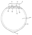
図2は本発明にかかるシート状蓋体の第1実施形態を示す平面図であり、シート状蓋体1は略M字形状半切線10がその両端部Bを前記シート状蓋体1の周縁に位置するように、かつ、その周縁側に向く凸部Aが前記周状熱接着部となる周状予定熱接着部5の内縁に当接しないように表面側から1個形成されると共に前記略M字形状半切線10と略対向する前記シート状蓋体1の周縁に開封用兼注湯口形成用摘まみ突片3を備えている。このように構成したシート状蓋体1は、前記略M字形状半切線10の部分を押圧して半切線を切断して前記略M字形状半切線10の形状からなる排湯口を形成し、この排湯口から湯切りすると前記凸部Aの働きにより麺の流出を防止して湯切りすることができる。なお、前記略M字形状半切線10の大きさは湯切り時間や麺の太さ等により適宜決められるべきものである。
【0016】
図3は本発明にかかるシート状蓋体の第2実施形態を示す図2に対応する図であって、シート状蓋体1’は略M字形状半切線10がその両端部Bを前記シート状蓋体1の周縁に位置するように、かつ、その周縁側に向く凸部Aが前記周状熱接着部(図示せず)となる周状予定熱接着部5の内縁に当接しないように表面側から等間隔に並列に3個形成された以外は図2に示した第1実施形態と同じである。このように構成したシート状蓋体1’は、前記略M字形状半切線10の部分を押圧することにより3つの前記略M字形状半切線10の形状からなる排湯口が形成されるために湯切り時間を短くすることができる。なお、前記略M字形状半切線10の大きさや個数(図3上は3個)は湯切り時間や麺の太さ等により適宜決められるべきものである。
【0017】
図4は本発明にかかるシート状蓋体の第3実施形態を示す図2に対応する図であって、シート状蓋体1”は図1に示した第1実施形態の略M字形状半切線10の一方の端部Bから他方の端部Bに至る残片除去用摘まみ突片4を周縁に突出形成したものであって、これ以外は図1に示した第1実施形態と同じである。このように構成したシート状蓋体1”は湯戻し後にシート状蓋体1”を完全に剥離した際に容器本体の上周面に残る1個の略M字形状の残片を残片除去用摘まみ突片4を手指で摘まんで剥離することにより美麗な開口部を得ることができるために気持ちよく喫食することができる。
【0018】
図5は本発明にかかるシート状蓋体の第4実施形態を示す図2に対応する図であって、シート状蓋体1'''は図3に示した第2実施形態の前記略M字形状半切線10の隣接しない2つの端部B’の一方から他方に至る残片除去用摘まみ突片4を周縁に突出形成し、かつ、前記略M字形状半切線10の隣接する端部Bを略U字形状の連結半切線11で結んだものであって、これ以外は図3に示した第2実施形態と同じである。このように構成したシート状蓋体1'''は湯戻し後にシート状蓋体1'''を完全に剥離した際に容器本体の上周面に残る3個の略M字形状の残片を残片除去用摘まみ突片4を手指で摘まんで剥離することにより3個の残片をワンアクションで全部剥離し取り除くことができると共に美麗な開口部を得ることができるために気持ちよく喫食することができる。なお、図5においては前記残片除去用摘まみ突片4の両側部に出っ張り部Cを設けた構成としたが、このように構成することにより、いずれかの出っ張り部Cを手指で摘まむことができ、左右どちらの利き腕の人にも対応することができる。当然のことであるが、利き腕を考慮しないのであればいずれか一方の側部に出っ張り部Cを設けた構成としてもよいものである。また、図3に示した第2実施形態同様に前記略M字形状半切線10の大きさや個数(図5上は3個)は湯切り時間や麺の太さ等により適宜決められるべきものである。
【0019】
図6は本発明にかかるシート状蓋体の第5実施形態を示す図5に対応する図であって、シート状蓋体1””はその表面に略M字形状半切線10を切断して排湯口を形成するための手指等での押圧位置を示す○印からなる表示12が表示手段の一つとして印刷により設けられているものであって、これ以外は図5に示した第4実施形態と同じである。このように構成したシート状蓋体1””は、排湯口を設けるための押圧位置を一目で確認することができ、誰でも確実に排湯口を形成することができる。なお、この押圧位置の表示は使用者に押圧位置が明確に確認することができるものであればよいのであって、図6に示した○印からなる表示12に限るものでないし、また、印刷以外の表示手段であってもよいものである。
【0020】
次に、本発明のシート状蓋体1、1’、1”、1''',1””の層構成および略M字形状半切線10の形成方法について説明する。シート状蓋体の層構成としては特に限定するものではないが、通常美麗な印刷が施されると共に容器本体との熱接着性が求められるために、シート状蓋体は印刷適性に優れた基材層と熱接着性樹脂層とを少なくとも備えた構成からなるが、これ以外に必要に応じてシートとしたときのフラット性や腰、あるいは、意匠性、あるいは、遮光性やガスバリアー性等を考慮して、これらの物性を付与するための付与層が熱接着性樹脂層より基材層側に適宜設けられる。そして、このような層構成からなるシート状蓋体に形成される略M字形状半切線10は、この部分を押圧することにより容易にシート状蓋体を切断して略M字形状の排湯口が形成可能なように、また、埃等が容器内に侵入しないように、少なくとも表出層の一部を残して表側ないし裏側から切刃で形成されるし、また、必要によっては表裏の表出層の少なくとも一部を残して中間層に設けてもよいものである。
【0021】
シート状蓋体1、1’、1”、1''',1””の層構成と略M字形状半切線10を設ける位置関係を例示するならば、▲1▼紙層(基材層)/ポリエチレン層/アルミニウム箔(付与層)/熱接着性樹脂層、▲2▼二軸延伸ポリエチレンテレフタレートフィルム(付与層)/接着剤層/紙層(基材層)/ポリエチレン層/アルミニウム箔(付与層)/熱接着性樹脂層、▲3▼二軸延伸ポリエチレンテレフタレートフィルム(付与層)/ポリエチレン層/紙層(基材層)/熱接着性樹脂層、▲4▼紙層 (基材層)/ポリエチレン層/二軸延伸ポリエチレンテレフタレートフィルム(付与層)/熱接着性樹脂層等を挙げることができる。なお、略M字形状半切線10は下線で示した層に表側から設けられているが、上記▲4▼の層構成にあっては、裏側(熱接着性樹脂層側)から紙層の一部に達するように設けてもよいものである。
【0022】
ところで、前記熱接着性樹脂層としては、容器本体30と剥離可能に熱接着するように構成する必要があり、容器本体30を構成する材料により適宜選択して用いることが肝要であるが、通常容器本体30はポリスチレンペーパー、ハイインパクトポリスチレンシート、ポリプロピレンシート、ポリアミドとポリエチレンないしポリプロピレンとの積層シート、ポリエチレンとポリプロピレンとの積層シート等を周知の真空成形法や圧空成形法で成形して容器としたもの、ポリプロピレン、ポリスチレン、ポリエステル等の射出成形用樹脂を射出成形して容器としたもの、あるいは、各種の射出成形用樹脂を多層で射出成形して、たとえば、酸素ガスバリアー性等をもたせたもの、あるいは、発泡スチレン製容器、紙製容器、あるいは、これらからなる二重容器などが用いられるために、前記熱接着性樹脂層としてはポリエチレン、ポリプロピレン、ポリブテン、エチレン−プロピレン共重合体、エチレン−酢酸ビニル共重合体、塩素化ポリエチレン、塩素化ポリプロピレン、アイオノマー樹脂、塩化ビニル−酢酸ビニル共重合体、アクリル酸樹脂、メタクリル酸樹脂、エチレン−アクリル酸共重合体、エチレン−メタクリル酸共重合体、エチレン−アクリル酸エステル共重合体、エチレン−メタクリル酸エステル共重合体、ポリエステル樹脂等から適宜選択して用いればよいものである。
【0023】
図7は本発明にかかるシート状蓋体の第6実施形態を示す透視平面図であって、シート状蓋体1””’は表面側から紙層/ポリエチレン層/アルミニウム箔/熱接着性樹脂層が順に積層された構成からなり、図5に示した第4実施形態のシート状蓋体1'''と同様の略M字形状半切線10と略U字形状の連結半切線11とが表面側から前記紙層の一部に達するように、もしくは、前記紙層を貫通して形成されると共に前記熱接着性樹脂層の前記略M字形状半切線に対応するように裏面側から前記熱接着性樹脂層を貫通する帯状の傷痕群6が形成されているものである。このように構成した前記シート状蓋体1””’は略M字形状半切線10の部分を手指等で押圧して略M字形状の排湯口を形成する際に、押圧する力が弱くても簡単に排湯口を形成することができる。なお、前記傷痕群6を帯状としたがこれに限るものではなく、少なくとも前記熱接着性樹脂層の前記略M字形状半切線10に対応する位置に裏面側から前記熱接着性樹脂層を貫通するように形成されていればよいものである。また、図示はしないが、図2〜4に示した第1〜第3実施形態にこの傷痕群6を適用してもよいものである。
【0024】
また、前記傷痕群6を構成する傷痕の形状としては、たとえば、点状、直線状、円弧状、V字状、Y字状、×ないし+形状等の任意の形状を採ることができると共に個々の傷痕の大きさ及び密度はシート状蓋体の層構成、熱接着性樹脂層の厚さや樹脂種等を考慮して適宜決められるべきものである。そして、前記傷痕群6の形成方法としては、たとえば、円筒状の周面に上記したような形状の突起を所定の大きさ及び所定の密度で備えた金属ロールでシート状蓋体が抜き加工される前の長尺ロール状態の時に前記熱接着性樹脂層側から押圧することにより容易に形成することができる。
【0025】
【発明の効果】
本発明のシート状蓋体は、今まで縷々説明してきたように、従来技術の項で説明したような蓋体に比べて、単に排湯口とするための略M字形状半切線を設けるだけという単純な構成からなるために、良好な生産性を確保することができる、また、排湯口の形成は略M字形状半切線の部分を手指等で押圧して略M字形状半切線を切断するだけで略M字形状の排湯口を確実に形成することができると共にシート状蓋体の略M字形状半切線が形成されていない表出層の前記略M字形状半切線に対応する位置に前記略M字形状半切線が形成されていない表出層を貫通する傷痕群を形成することにより一層弱い押圧力で略M字形状の排湯口を確実に形成することができる、また、残片除去用摘まみ突片を設けたことにより、ワンアクションで容器本体の上周面に残った残片を全部取り除くことができると共に美麗な開口部を得ることができるために気持ちよく喫食することができる、また、本発明のシート状蓋体は、容器としての密封性に優れ、湯切り操作の手間がかからずに簡便、迅速、かつ、安全、確実に湯切りすることができる、等々の優れた効果を奏するものである。
【図面の簡単な説明】
【図1】 本発明にかかるシート状蓋体を用いた容器の一実施例を示す概略斜視図である。
【図2】 本発明にかかるシート状蓋体の第1実施形態を示す平面図である。
【図3】 本発明にかかるシート状蓋体の第2実施形態を示す図2に対応する図である。
【図4】 本発明にかかるシート状蓋体の第3実施形態を示す図2に対応する図である。
【図5】 本発明にかかるシート状蓋体の第4実施形態を示す図2に対応する図である。
【図6】 本発明かかるシート状蓋体の第5実施形態を示す図5に対応する図である。
【図7】 本発明にかかるシート状蓋体の第6実施形態を示す透視平面図である。
【符号の説明】
1,1’,1”,1’’’ シート状蓋体
1””,1””’ シート状蓋体
3 開封用兼注湯口形成用摘まみ突片
4 残片除去用摘まみ突片
5 周状予定熱接着部
6 帯状の傷痕群
10 略M字形状半切線
11 連結半切線
12 押圧位置の表示
20 容器
30 容器本体
31 上周面
A 凸部
B,B' 端部
C 出っ張り部[0001]
BACKGROUND OF THE INVENTION
TECHNICAL FIELD The present invention relates to a lid used for packaging containers such as instant noodles, and more specifically, a sheet-like lid used for performing hot water draining after tempering noodles in a container like instant foods such as fried noodles and raw noodles. It is about the body.
[0002]
[Prior art]
Conventionally, containers used by sipping noodles in a container typified by yakisoba or raw noodles and then draining hot water are instant noodles such as fried noodles and bag noodles in a plastic molded container body such as expanded polystyrene, It is generally used in a form that contains ingredients, seasonings, etc., and a plastic molded lid with a notch to be used as a hot water cut hole is fitted to the plastic molded container body and the whole is wrapped in a shrink film Has been.
[0003]
This kind of container has a problem that the operation of attaching and detaching the lid to the container body is troublesome, the operation of raising the notch provided in the lid and securing the through hole is quite troublesome, and the finger is not used when raising the notch with fingers. There are problems such as injuries, and notches for securing through holes can only be formed in part of the flange, so it takes some time to drain the hot water. Although it must be held and drained, there is a risk that hot water may be spilled due to the large amount of hot water required for reconstitution with respect to the capacity of the container. There is a problem that there is a risk, when the hot water drains, the container must be tilted and the hot water must be discharged from the through hole, but a considerable weight of noodles containing hot water is unevenly distributed on one side, so that the lid does not come off from the container body container The body and lid must be pressed with a force greater than the specified level, the fingers get tired and hot, and sometimes the spilled noodles are spilled from the container. However, the container body and the lid are not sealed, and there is a problem that insects or the like may be mixed.
[0004]
In order to solve the above problem, for example, a lid disclosed in Japanese Utility Model Publication No. 61-3810 has been developed. That is, the lid disclosed in Japanese Utility Model Publication No. 61-3810 is composed of a front base material and a back base material, and a half cut (drainage) is formed on the back base material by peeling the front base material. The part of the hot water forming half cut line) is cut out together with the front substrate side to form a hot water outlet, and the hot water is cut from this hot water outlet.
[0005]
However, the lid described in Japanese Utility Model Publication No. 61-3810 has a peeling region between the front substrate and the back substrate, an adjacent non-peeling region adjacent thereto, and an independent non-peeling region within the peeling region. It is necessary to form the hot water outlet forming half cut so as to coincide with the independent non-peeling region, but when forming the hot water outlet forming half cut (half-cut line for forming the hot water outlet) Since the peeling region exists between the front substrate and the back substrate, it cannot be visually confirmed. Since this positioning operation is quite complicated, the productivity is low, and the independent non-peeling region and this If the position of the half cut for forming the hot water outlet (half cut line for forming the hot water outlet) is shifted, a fatal problem that the hot water outlet cannot be formed occurs.
[0006]
[Problems to be solved by the invention]
Accordingly, the present invention has been made to solve the above-described problems, and an object of the present invention is a sheet-like lid body that has good productivity and can reliably form a hot water outlet. Thus, it is an object of the present invention to provide a sheet-like lid that has excellent sealing properties as a container and can be easily, quickly, safely, and reliably cut off hot water without the need for hot water cutting operations.
[0007]
[Means for Solving the Problems]
In order to solve the above-mentioned problems, the present inventor is a heat bonding method in which the upper peripheral surface forming the opening portion of the bottomed container body having an opening portion on the upper surface is peelable by a circumferential heat bonding portion. In the sheet-like lid having substantially the same outer shape as the opening to be sealed, a substantially M-shaped half-cut line is positioned at both ends of the sheet-like lid on the periphery of the sheet-like lid, and One or a plurality of projections facing the peripheral side are formed in parallel so as not to contact the inner edge of the circumferential thermal bonding portion that becomes the circumferential thermal bonding portion, and on the circumferential edge of the sheet-like lid The present invention is characterized by comprising a picking protrusion for opening and pouring the pouring gate.
[0008]
By adopting the above configuration , for example, a finger picking a picking piece for opening and pouring a pouring gate of a sheet-like lid attached to a container body containing raw noodles in a bag and the like is peeled and thermally bonded. Then, peel off the sheet-like lid from the container, open the container about half, take out the raw noodles in the bag contained in the container in this state, open the bag, and only the raw noodles or raw noodles and utensils Return the container to the container and press the part of the approximately M-shaped half-cut line with your fingers to form the approximately M-shaped hot water outlet. Then, pour hot water and return the sheet-like lid to the original closed position again. Hot water is returned for a predetermined time, and then the hot water is drained from this hot water outlet. At the time of hot water cutting, the convex portion of the substantially M-shaped hot water outlet can prevent the noodles from flowing out, thereby enabling quick hot water cutting. After that, the sheet-like lid is completely peeled off, and seasoning such as soup stock is poured on the raw noodles that have been reconstituted with hot water, and hot water is poured into the noodles, and a condiment such as the seven tastes is added to eat. As described above, the sheet-like lid of the present invention has an independent non-peeling region and a drain port without forming a peeling region, an adjacent non-peeling region, and an independent non-peeling region between base materials as described in the section of the prior art. Since it has a simple configuration in which only a substantially M-shaped half-cut line for providing a hot water outlet is provided without complicated alignment with the forming half-cut line, it is possible to ensure good productivity. A hot water outlet can be formed reliably. In addition, the sheet-like lid of the present invention has excellent sealing properties as a container, and can easily, quickly, safely, and reliably perform hot water draining without the need for hot water draining operations.
[0009]
Further, the present invention is substantially the same outer shape as the opening that is thermally bonded so as to be peeled off by a circumferential heat bonding portion on the upper peripheral surface of the bottomed container body having the opening on the upper surface, and is peeled off by a circumferential heat bonding portion. In the sheet-like lid, a substantially M-shaped half-cut line is located on the edge of the sheet-like lid so that both ends thereof are located at the periphery of the sheet-like lid, and the convex portion facing the circumferential side is the circumferential shape. One piece is provided so as not to come into contact with the inner edge of the circumferentially scheduled heat-bonding portion serving as the heat-bonding portion, and a remaining piece removing knob projecting piece extending from one end portion to the other end portion of the sheet-like lid The sheet-like lid body is formed with a projecting protrusion for opening and pouring gate, and is provided with a protruding protrusion for forming a pouring gate. By configuring in this way, when the sheet-like lid is completely peeled off after reconstitution, the approximately M-shaped remnant remaining on the upper peripheral surface of the container body is picked and peeled off with a finger for removing the remaining piece. Can be eaten comfortably because it can obtain a beautiful opening.
[0010]
Further, the present invention is substantially the same outer shape as the opening that is thermally bonded so as to be peeled off by a circumferential heat bonding portion on the upper peripheral surface of the bottomed container body having the opening on the upper surface, and is peeled off by a circumferential heat bonding portion. In the sheet-like lid, a substantially M-shaped half-cut line is located on the edge of the sheet-like lid so that both ends thereof are located at the periphery of the sheet-like lid, and the convex portion facing the circumferential side is the circumferential shape. A plurality of parallel formed so as not to come into contact with the inner edge of the circumferential predetermined thermal bonding portion to be the thermal bonding portion, and from one end portion of two non-adjacent ends of the substantially M-shaped half-cut line to the other The sheet-like lid is formed with a pinch protrusion for removing the remaining pieces reaching the end portion and protruding at the periphery of the sheet-like lid body, and adjacent ends of the substantially M-shaped half-cut line are connected by a connecting half-cut line. It is characterized by having a picking piece for opening and pouring gate formation at the periphery of the body. By configuring in this way, a plurality of substantially M-shaped remnants remaining on the upper peripheral surface of the container main body when the sheet-like lid is completely peeled after reconstitution with hot water, use the fingers to hold the picking protrusions for removing the remnants. By picking and peeling, a plurality of remaining pieces can be peeled and removed all in one action, and a beautiful opening can be obtained.
[0011]
Further, in any one of the sheet-like lids described above, the substantially M-shaped portion is located at a position corresponding to the substantially M-shaped half-cut line of the exposed layer where the substantially M-shaped half-cut line of the sheet-like lid body is not formed. A scar group penetrating the exposed layer in which the character-shaped half-cut line is not formed is formed. By configuring in this way, when forming a substantially M-shaped hot water outlet by pressing the substantially M-shaped half-cut line portion with fingers or the like, the hot water outlet is easily formed even if the pressing force is weak. be able to.
[0012]
Further, in the sheet-shaped cover body according to any one of the above-described pressing for forming a discharge sprue by cutting the substantially M-shaped half cut lines formed in the sheet lid on the surface of the sheet-shaped cover body The display means for indicating the position is provided. By comprising in this way, a press position can be confirmed at a glance and a hot water outlet can be formed reliably.
[0013]
DETAILED DESCRIPTION OF THE INVENTION
The above-described present invention will be described in detail below with reference to the drawings.
FIG. 1 is a schematic perspective view showing an embodiment of a container using a sheet-like lid according to the present invention, FIG. 2 is a plan view showing a first embodiment of the sheet-like lid according to the present invention, and FIG. The figure corresponding to FIG. 2 which shows 2nd Embodiment of the sheet-like lid concerning invention, FIG. 4 is a figure corresponding to FIG. 2 which shows 3rd Embodiment of the sheet-like lid concerning this invention, FIG. 5 is this FIG. 6 is a diagram corresponding to FIG. 2 showing a fifth embodiment of the sheet-like lid according to the present invention, FIG. 6 is a diagram corresponding to FIG. 5 showing the fifth embodiment of the sheet-like lid according to the present invention, and FIG. FIG. 9 is a perspective plan view showing a sixth embodiment of the sheet-like lid according to the embodiment, in which 1, 1 ′, 1 ″, 1 ′ ″, 1 ″ ″, 1 ″ ″ ′ denote sheet-like lids, 3 Is a picking piece for forming an opening and pouring gate, 4 is a picking piece for removing a residue, 5 is a thermal bonding portion scheduled to be circumferential, 6 is a band-shaped scar group, 10 is a substantially M-shaped half-cut line, 1 The coupling half cut line, 12 is a display of the pressed position, 20 container, 30
[0014]
FIG. 1 is a schematic perspective view showing an embodiment of a container using a sheet-like lid according to the present invention, and the
[0015]
FIG. 2 is a plan view showing a first embodiment of a sheet-like lid according to the present invention. The sheet-
[0016]
FIG. 3 is a view corresponding to FIG. 2 showing a second embodiment of the sheet-like lid according to the present invention, in which the sheet-
[0017]
FIG. 4 is a view corresponding to FIG. 2 showing a third embodiment of the sheet-like lid according to the present invention. The sheet-
[0018]
FIG. 5 is a view corresponding to FIG. 2 showing a fourth embodiment of a sheet-like lid according to the present invention, and the sheet-
[0019]
FIG. 6 is a view corresponding to FIG. 5 showing a fifth embodiment of the sheet-like lid according to the present invention. The sheet-
[0020]
Next, the layer structure of the sheet-
[0021]
To illustrate the positional relationship in which the layer structure of the sheet-
[0022]
By the way, the heat-adhesive resin layer needs to be configured so as to be heat-bondable to the container
[0023]
FIG. 7 is a perspective plan view showing a sheet-like lid according to a sixth embodiment of the present invention. The sheet-
[0024]
Further, as the shape of the scar constituting the scar group 6, for example, an arbitrary shape such as a dot shape, a linear shape, an arc shape, a V shape, a Y shape, an X shape or a + shape can be adopted. The size and density of the scratches should be appropriately determined in consideration of the layer structure of the sheet-like lid, the thickness of the heat-adhesive resin layer, the resin type, and the like. As a method for forming the scar group 6, for example, the sheet-like lid body is punched out with a metal roll having projections of the shape described above on a cylindrical peripheral surface with a predetermined size and a predetermined density. It can be easily formed by pressing from the side of the heat-adhesive resin layer in the state of a long roll before being rolled.
[0025]
【The invention's effect】
The sheet-like lid of the present invention, as has been frequently described so far, is merely provided with a substantially M-shaped half-cut line for serving as a hot water outlet, as compared with the lid as described in the section of the prior art. Since it has a simple configuration, it is possible to ensure good productivity. In addition, the hot water outlet is formed by pressing the substantially M-shaped half-cut line portion with a finger or the like to cut the substantially M-shaped half-cut line. In the position corresponding to the substantially M-shaped half-cut line of the exposed layer, the substantially M-shaped hot water outlet can be surely formed only by this, and the substantially M-shaped half-cut line of the sheet-like lid is not formed. By forming a scar group penetrating the exposed layer in which the substantially M-shaped half-cut line is not formed, a substantially M-shaped hot water outlet can be reliably formed with a weaker pressing force. By providing a picking piece for the container body, It is possible to remove all the remaining pieces on the peripheral surface and obtain a beautiful opening, so that it can be eaten comfortably, and the sheet-like lid of the present invention is excellent in sealing performance as a container, The present invention provides excellent effects such as simple, rapid, safe and reliable hot water cutting without the need for hot water cutting operation.
[Brief description of the drawings]
FIG. 1 is a schematic perspective view showing an embodiment of a container using a sheet-like lid according to the present invention.
FIG. 2 is a plan view showing a first embodiment of a sheet-like lid according to the present invention.
FIG. 3 is a view corresponding to FIG. 2 showing a second embodiment of the sheet-like lid according to the present invention.
FIG. 4 is a view corresponding to FIG. 2 showing a third embodiment of the sheet-like lid according to the present invention.
FIG. 5 is a view corresponding to FIG. 2 showing a fourth embodiment of the sheet-like lid according to the present invention.
FIG. 6 is a view corresponding to FIG. 5 showing a fifth embodiment of the sheet-like lid according to the present invention.
FIG. 7 is a perspective plan view showing a sixth embodiment of a sheet-like lid according to the present invention.
[Explanation of symbols]
1, 1 ′, 1 ″, 1 ′ ″ Sheet-
Claims (4)
前記シート状蓋体の表面に前記シート状蓋体に形成した前記略M字形状半切線を切断して排湯口を形成するための押圧位置を示す表示手段が設けられていることを特徴とする、シート状蓋体。In a sheet-like lid body having substantially the same outer shape as the opening portion that is thermally bonded so as to be peeled off by a circumferential heat bonding portion on the upper peripheral surface forming the opening portion of the bottomed container body having an opening portion on the upper surface. The sheet-shaped lid body has a substantially M-shaped half-cut line positioned at both ends of the sheet-shaped lid body at the peripheral edge of the sheet-shaped lid body, and a convex portion facing the peripheral edge serves as the circumferential thermal bonding portion. One or a plurality in parallel so as not to come into contact with the inner edge of the pre-scheduled heat-bonding part, and provided with a picking piece for opening and pouring gate formation on the periphery of the sheet-like lid ,
Display means is provided on the surface of the sheet-like lid for indicating a pressing position for cutting the substantially M-shaped half-cut line formed on the sheet-like lid to form a hot water outlet. , Sheet-like lid.
前記シート状蓋体の表面に前記シート状蓋体に形成した前記略M字形状半切線を切断して排湯口を形成するための押圧位置を示す表示手段が設けられていることを特徴とする、シート状蓋体。In a sheet-like lid body having substantially the same outer shape as the opening portion that is thermally bonded so as to be peeled off by a circumferential heat bonding portion on the upper peripheral surface forming the opening portion of the bottomed container body having an opening portion on the upper surface. The sheet-shaped lid body has a substantially M-shaped half-cut line positioned at both ends of the sheet-shaped lid body at the peripheral edge of the sheet-shaped lid body, and a convex portion facing the peripheral edge serves as the circumferential thermal bonding portion. One piece is provided so as not to come into contact with the inner edge of the pre-scheduled heat-bonding portion, and a remaining piece removing knob projecting piece extending from one end portion to the other end portion is formed protruding from the periphery of the sheet-like lid. In addition, it is provided with a picking piece for opening and pouring gate formation on the periphery of the sheet-like lid ,
Display means is provided on the surface of the sheet-like lid for indicating a pressing position for cutting the substantially M-shaped half-cut line formed on the sheet-like lid to form a hot water outlet. , Sheet-like lid.
前記シート状蓋体の表面に前記シート状蓋体に形成した前記略M字形状半切線を切断して排湯口を形成するための押圧位置を示す表示手段が設けられていることを特徴とする、シート状蓋体。In a sheet-like lid body having substantially the same outer shape as the opening portion that is thermally bonded so as to be peeled off by a circumferential heat bonding portion on the upper peripheral surface forming the opening portion of the bottomed container body having an opening portion on the upper surface. The sheet-shaped lid body has a substantially M-shaped half-cut line positioned at both ends of the sheet-shaped lid body at the peripheral edge of the sheet-shaped lid body, and a convex portion facing the peripheral edge serves as the circumferential thermal bonding portion. A plurality of juxtaposed strip removal protrusions formed in parallel so as not to come into contact with the inner edge of the pre-scheduled heat-bonding portion and extending from one of two non-adjacent ends of the substantially M-shaped half-cut line to the other; The sheet-shaped lid is formed so as to protrude from the periphery of the sheet-like lid, and adjacent ends of the substantially M-shaped half-cut line are connected by a connecting half-cut line. It has a mami protruding piece ,
Display means is provided on the surface of the sheet-like lid for indicating a pressing position for cutting the substantially M-shaped half-cut line formed on the sheet-like lid to form a hot water outlet. , Sheet-like lid.
Priority Applications (1)
| Application Number | Priority Date | Filing Date | Title |
|---|---|---|---|
| JP2002190845A JP4138376B2 (en) | 2002-01-25 | 2002-06-28 | Sheet-like lid |
Applications Claiming Priority (3)
| Application Number | Priority Date | Filing Date | Title |
|---|---|---|---|
| JP2002017415 | 2002-01-25 | ||
| JP2002-17415 | 2002-01-25 | ||
| JP2002190845A JP4138376B2 (en) | 2002-01-25 | 2002-06-28 | Sheet-like lid |
Publications (2)
| Publication Number | Publication Date |
|---|---|
| JP2003285882A JP2003285882A (en) | 2003-10-07 |
| JP4138376B2 true JP4138376B2 (en) | 2008-08-27 |
Family
ID=29253221
Family Applications (1)
| Application Number | Title | Priority Date | Filing Date |
|---|---|---|---|
| JP2002190845A Expired - Fee Related JP4138376B2 (en) | 2002-01-25 | 2002-06-28 | Sheet-like lid |
Country Status (1)
| Country | Link |
|---|---|
| JP (1) | JP4138376B2 (en) |
-
2002
- 2002-06-28 JP JP2002190845A patent/JP4138376B2/en not_active Expired - Fee Related
Also Published As
| Publication number | Publication date |
|---|---|
| JP2003285882A (en) | 2003-10-07 |
Similar Documents
| Publication | Publication Date | Title |
|---|---|---|
| JP2000203654A (en) | Lid material with hot-water drain hole | |
| JP2001122320A (en) | Instant food container lid with hot water dripping function | |
| JP4138376B2 (en) | Sheet-like lid | |
| JP5447843B2 (en) | Lid material | |
| KR100948324B1 (en) | Cover material with hot water cutting holes | |
| JP3949985B2 (en) | Lid with hot water hole | |
| JP2004059049A (en) | Lid material with hole for dripping hot water | |
| JP4729787B2 (en) | Lid with hot water draining function | |
| JP3892731B2 (en) | Lid with hot water hole | |
| JP4231311B2 (en) | Sheet-like lid | |
| JP4357897B2 (en) | Sheet-like lid | |
| JP4089241B2 (en) | Lid with lid | |
| JP2003040354A (en) | Lid with hot water draining holes | |
| JP2002046763A (en) | Easily peelable lid material | |
| JP3949970B2 (en) | Lid with hot water hole | |
| JP3034765U (en) | Packaging bag | |
| JP3933481B2 (en) | Lid with hot water hole | |
| JPH11278555A (en) | Lid material with hole for draining hot water | |
| JP6089544B2 (en) | Lid material with hot water cutting function and container using the lid material | |
| JP4231300B2 (en) | Sheet-like lid | |
| JP4863037B2 (en) | container | |
| JP4202713B2 (en) | Instant food containers | |
| JP2008007145A (en) | Lid material with hot water draining function | |
| JP4231173B2 (en) | Lid with hot water hole | |
| JP2002160777A (en) | Instant food container with hot water draining function |
Legal Events
| Date | Code | Title | Description |
|---|---|---|---|
| A621 | Written request for application examination |
Free format text: JAPANESE INTERMEDIATE CODE: A621 Effective date: 20050510 |
|
| A977 | Report on retrieval |
Free format text: JAPANESE INTERMEDIATE CODE: A971007 Effective date: 20080131 |
|
| A131 | Notification of reasons for refusal |
Free format text: JAPANESE INTERMEDIATE CODE: A131 Effective date: 20080205 |
|
| A521 | Written amendment |
Free format text: JAPANESE INTERMEDIATE CODE: A523 Effective date: 20080404 |
|
| TRDD | Decision of grant or rejection written | ||
| A01 | Written decision to grant a patent or to grant a registration (utility model) |
Free format text: JAPANESE INTERMEDIATE CODE: A01 Effective date: 20080507 |
|
| A01 | Written decision to grant a patent or to grant a registration (utility model) |
Free format text: JAPANESE INTERMEDIATE CODE: A01 |
|
| A61 | First payment of annual fees (during grant procedure) |
Free format text: JAPANESE INTERMEDIATE CODE: A61 Effective date: 20080605 |
|
| R150 | Certificate of patent or registration of utility model |
Ref document number: 4138376 Country of ref document: JP Free format text: JAPANESE INTERMEDIATE CODE: R150 Free format text: JAPANESE INTERMEDIATE CODE: R150 |
|
| FPAY | Renewal fee payment (event date is renewal date of database) |
Free format text: PAYMENT UNTIL: 20110613 Year of fee payment: 3 |
|
| S533 | Written request for registration of change of name |
Free format text: JAPANESE INTERMEDIATE CODE: R313533 |
|
| FPAY | Renewal fee payment (event date is renewal date of database) |
Free format text: PAYMENT UNTIL: 20110613 Year of fee payment: 3 |
|
| R350 | Written notification of registration of transfer |
Free format text: JAPANESE INTERMEDIATE CODE: R350 |
|
| FPAY | Renewal fee payment (event date is renewal date of database) |
Free format text: PAYMENT UNTIL: 20110613 Year of fee payment: 3 |
|
| FPAY | Renewal fee payment (event date is renewal date of database) |
Free format text: PAYMENT UNTIL: 20140613 Year of fee payment: 6 |
|
| R250 | Receipt of annual fees |
Free format text: JAPANESE INTERMEDIATE CODE: R250 |
|
| R250 | Receipt of annual fees |
Free format text: JAPANESE INTERMEDIATE CODE: R250 |
|
| R250 | Receipt of annual fees |
Free format text: JAPANESE INTERMEDIATE CODE: R250 |
|
| R250 | Receipt of annual fees |
Free format text: JAPANESE INTERMEDIATE CODE: R250 |
|
| LAPS | Cancellation because of no payment of annual fees |