JP4136245B2 - Process cartridge and image forming apparatus - Google Patents
Process cartridge and image forming apparatus Download PDFInfo
- Publication number
- JP4136245B2 JP4136245B2 JP2000009478A JP2000009478A JP4136245B2 JP 4136245 B2 JP4136245 B2 JP 4136245B2 JP 2000009478 A JP2000009478 A JP 2000009478A JP 2000009478 A JP2000009478 A JP 2000009478A JP 4136245 B2 JP4136245 B2 JP 4136245B2
- Authority
- JP
- Japan
- Prior art keywords
- image
- roller
- process cartridge
- charging roller
- image carrier
- Prior art date
- Legal status (The legal status is an assumption and is not a legal conclusion. Google has not performed a legal analysis and makes no representation as to the accuracy of the status listed.)
- Expired - Fee Related
Links
Images


Description
【0001】
【発明の属する技術分野】
本発明は、複写機、レーザプリンタ、ファクシミリ等に使用されるプロセスカートリッジ及び画像形成装置に関する。
【0002】
【従来の技術】
複写機、レーザプリンタ、ファクシミリ等の画像形成装置は、帯電装置によって一様に帯電された感光ドラム(像担持体)に選択的な露光を行って静電潜像を形成し、この静電潜像を現像装置によってトナーを付着させてトナー像として現像し、その後、このトナー像を紙等の記録材に転写して画像を形成する。そして、トナー像の転写後の感光ドラムは、表面に残留したトナーをクリーニング装置で除去されて、次の画像形成に供される。
【0003】
近年では、感光ドラム、帯電装置、現像装置、クリーニング装置等をカートリッジ容器に一体的に組み込んでプロセスカートリッジとしてカートリッジ化したものが知られている。このプロセスカートリッジは、画像形成装置本体に対して着脱自在に構成されているので、これをユーザが画像形成装置本体に装着することによって、トナーの供給や感光ドラムの交換をユーザ自身で簡単に行うことができ、メンテナンスの容易化を図っている。
【0004】
さらに近年では、イエロー、マゼンタ、シアン、ブラックのそれぞれ独立した現像器を、感光ドラムに対して選択的に配設して現像動作を行う、又は感光ドラムに対して固定的に配設しそれぞれの現像器を選択的に駆動することにより、多色画像を形成する画像形成装置も考案されており、この多色の画像形成装置に用いられるプロセスカートリッジも実用化されるようになってきている。
【0005】
ここで上述のプロセスカートリッジにおける帯電装置としては、コロナ放電等を用いた非接触方式と、帯電ローラ等を用いた接触方式が一般的であるが、近年ではオゾン発生の防止等を目的に後者の接触方式が一般的に用いられるようになってきている。
【0006】
【発明が解決しようとする課題】
しかしながら、上述の接触方式の帯電装置は、感光ドラムに対して長期間接触させたままの状態に放置しておくと、帯電部材(例えば帯電ローラ)のうちの感光ドラムと接触する部分が永久変形を起こし帯電能力に変化をきたし、濃度ムラ等の画像不良を生じる場合があった。また感光ドラム表面においても、プロセスカートリッジの運搬時の振動等により感光ドラムと帯電部材とが摺擦し、帯電メモリとして履歴が残り、濃度ムラ等の画像不良を生じる場合があった。
【0007】
これらの解決手段としては、従来から感光ドラム表面と帯電部材との間であって特に画像が書き込まれる領域(画像形成領域)の外側の領域(非画像形成領域)にスペーサ部材を挟み込み、未使用状態(特に搬送時)に両者を離間させた状態に保持しておく方法(特開平2−39169号公報)やソレノイドを用いて加圧・離間を行う方法(特開平3−48879号公報)等が開示されているが、これらの方法によると、プロセスカートリッジの使用時にユーザが感光ドラムに帯電ローラを当接させなければならないためユーザの負担が大きくなることや、加圧・離間のための機構が複雑でコストがかかるという問題があった。
【0008】
本発明は、上述事情に鑑みてなされたものであり、画像ムラ等の画像不良を防止するために感光ドラムから帯電ローラを離間させているスペーサ部材の除去を、簡単な構成と、ユーザに負担をかけない簡単な動作とで行うことができるプロセスカートリッジ及び画像形成装置を提供することを目的とするものである。
【0009】
【課題を解決するための手段】
上述の目的を達成するための請求項1に係る本発明は、像担持体と、前記像担持体表面を帯電する帯電ローラと、現像ローラを備え、前記像担持体表面に形成された静電潜像にトナーを付着させてトナー像として現像する現像装置とをカートリッジ枠体に一体的に組み込んで構成され、画像形成装置本体に対して装着される着脱自在なプロセスカートリッジにおいて、前記像担持体表面に向けて前記帯電ローラを付勢する付勢部材と、前記付勢部材の付勢力に抗して前記帯電ローラの軸と前記像担持体との間に挿入されて前記像担持体表面から前記帯電ローラを離間させる第1の離間部材と、前記現像ローラと前記像担持体との間に挿入されて前記像担持体表面から前記現像ローラを離間させる第2の離間部材と、前記第1の離間部材と前記第2の離間部材とを連結する連結部材と、を備え、前記連結部材を介して連結した前記第1の離間部材と前記第2の離間部材とを前記像担持体の周方向に沿って前記カートリッジ枠体から引き抜くことで前記現像ローラを前記像担持体表面に当接させるとともに前記帯電ローラを前記像担持体表面に当接させ、前記第1の離間部材と前記第2の離間部材のうち、引き抜き方向の上流側に存在する離間部材を上流側離間部材として、前記上流側離間部材の前記像担持体半径方向の寸法は、前記帯電ローラ又は現像ローラのうち引き抜き方向の下流側に存在するローラと、前記像担持体とが接触した状態において、当該ローラの軸と前記像担持体との間を通過可能な大きさに設定され、且つ、前記上流側離間部材は、前記上流側離間部材の引き抜き経路上の前記カートリッジ枠体と前記像担持体表面との間を干渉することなく引き抜き可能に設定される、ことを特徴とする。
【0014】
請求項2に係る本発明は、請求項1のプロセスカートリッジにおいて、前記上流側離間部材に前記引き抜き方向と平行に溝を設け、前記カートリッジ枠体に前記溝に係合する壁状の規制部材を設けた、ことを特徴とする。
【0015】
請求項3に係る本発明は、画像形成装置本体と、前記画像形成装置本体に装着されて使用される着脱自在なプロセスカートリッジとを備えた画像形成装置において、前記プロセスカートリッジが請求項1又は2のプロセスカートリッジである、ことを特徴とする。
【0016】
【発明の実施の形態】
以下、図面に沿って、本発明の実施の形態について説明する。
【0017】
〈実施の形態〉
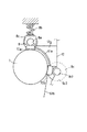
図1に、発明に係る画像形成装置の一例を示す。同図に示す画像形成装置は、電子写真方式のレーザビームプリンタであり、同図はその概略構成を示す縦断面図である。
【0018】
同時に示すレーザビームプリンタ(以下「画像形成装置」という。)Aは、電子写真プロセスによって記録材(例えば、紙、OHPシート、布等)に画像を形成するものであり、像担持体としてドラム形の電子写真感光体(以下「感光ドラム」という。)7を備えている。
【0019】
感光ドラム7は、駆動手段(不図示)によって矢印方向に所定のプロセススピードで回転駆動され、その表面が帯電ローラ(帯電部材)8によって所定の極性・電位に均一に帯電される。帯電後の感光ドラム7表面は、露光装置1によって画像情報に応じた光照射が行われ、これにより静電潜像が形成される。この静電潜像は、現像装置9によってトナー像として現像される。感光ドラム7上のトナー像は、転写ローラ(転写装置)4に印加された転写バイアスにより記録材2表面に転写される。トナー像転写後の記録材2は、定着装置5によって表面にトナー像が定着された後、画像形成装置本体14の外部に排出される。一方、トナー像転写後の感光ドラム7は、表面に残った転写残トナーがクリーニング装置10によって除去され、次の画像形成に供される。
【0020】
上述の露光装置1は、画像除法に基づいてレーザ光を発光するレーザダイオード1a、レーザ光を反射するポリゴンミラー1b、レンズ1c、反射ミラー1d等を有しており、これらにより、レーザ光を感光ドラム7表面に導く。
【0021】
また、給搬送装置3は、給紙カセット3a内に収納された記録材2を、ピックアップローラ3bによって給紙し、搬送ローラ対3c、3dによりレジストローラ対3eまで搬送して一旦停止させ、上述の感光ドラム7上のトナー像とタイミングを合わせるようにして、レジストローラ対3eによって感光ドラム7と転写ローラ4との間の転写部に供給する。さらに、トナー像転写後に記録材2を搬送ベルト3fによって定着装置8に搬送し、定着後の記録材2を搬送ローラ3g、フラッパ3kを介して排出ローラ3mにより画像形成装置本体14の外部に、又は定着後の記録材2をフラッパ3kの切り換えにより搬送ローラ3h、排出ガイド3j、排出ローラ3iを介して排紙トレイ6上に排出するものである。
【0022】
また、定着装置8は、ヒータ5aを内蔵した定着ローラ5bと、これに圧接されて定着ニップ部を形成する加圧ローラ5cとを有しており、未定着トナー像を担持した記録材2を加熱・加圧して表面にトナー像を定着するものである。
【0023】
次に、本発明に係るプロセスカートリッジBについて説明する。
【0024】
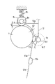
プロセスカートリッジBは、図3(縦断面図)、図4(右上方斜視図)、図5(右側面図)、図6(左側面図)に示すように、トナーを収納するトナー容器(現像剤収納部)11Aを有するトナー枠体11と、現像ローラ9cを有する現像装置9を保持する現像枠体12と結合し、さらにこれに感光ドラム7、クリーニングブレード10a等を有するクリーニングのクリーニング装置10及び接触帯電方式を用いた帯電装置である帯電ローラ8が取り付けられたクリーニング枠体13を結合してカートリッジ枠体(ハウジング)Yを構成している。そしてこのプロセスカートリッジBは、図1、図2に示すように、画像形成装置本体14に対し、その上面においてピン35aを中心に矢印方向に開閉自在なカバー35を開放して矢印X方向に装着し、また矢印X方向と反対方向に取り出すようになっている。
【0025】
[カートリッジ枠体構成]
次に本実施の形態に係るプロセスカートリッジBのハウジングYの構成について説明する。
【0026】
本実施の形態で示すプロセスカートリッジBは、トナー枠体11と現像枠体12とを結合し、これにクリーニング枠体13を回動可能に結合して構成したカートリッジ枠体としてのハウジングY内に、前述の感光ドラム7、帯電ローラ8、現像装置9及びクリーニング装置10等を収納してカートリッジ化したものである。そして、このプロセスカートリッジBを画像形成装置本体14に設けたカートリッジ装着手段に対し取り外し可能に装着する。
【0027】
図3及び図10に示すように、トナー枠体11にはトナー送り部材9bを回動可能に取り付けてあり、現像枠体12には現像ローラ9c及び現像ブレード9dを取り付けてある。そして前記トナー枠体11と現像枠体12を溶着(本実施の形態では超音波溶着)して一体的な第2枠体としての現像ユニットD(図8参照)を構成している。
【0028】
また、図3及び図10に示すようにクリーニング枠体13には感光ドラム7、帯電ローラ8、クリーニング装置10の各部材を取り付けて第1枠体としてのクリーニングユニットC(図7参照)を構成している。
【0029】
上述の現像ユニットDとクリーニングユニットCとを丸いピンの結合部材22によって互いに回動可能に結合することによってプロセスカートリッジBを構成する。すなわち、図8に示すように、現像枠体12の長手方向(現像ローラ9cの軸線方向)両側に形成したアーム部19の先端には現像ローラ9cに平行に丸い形状の回動穴20が設けてある。一方、クリーニング枠体13の長手方向両側2箇所にはアーム部19が侵入するための凹部21が設けてある(図7参照)。この凹部21にアーム部19を挿入し、結合部材22をクリーニング枠体13の取付穴13eに圧入し、かつアーム部19端の回動穴20に嵌入してさらに内側の穴13eに圧入して取り付けることにより、現像ユニットDとクリーニングユニットCは結合部材22に中心に回動可能に結合される。このときアーム部19の根本に立設したダボ(不図示)に挿入して取り付けた圧縮コイルばね22aがクリーニング枠体13の凹部21の上壁に当たりこの圧縮コイルばね22aによって現像枠体12を下方へ付勢することにより、現像ローラ9cを感光ドラム7へ確実に押し付ける。なお、クリーニング枠体13の凹部21の上壁は現像ユニットDとクリーニングユニットCを組み付ける際に圧縮コイルばね22aが非圧縮状態から圧縮を次第に強めるように傾斜が付されている。また、図8に示すように現像ローラ9cの長手方向両端に、感光ドラム7と現像ローラ9cの間隔を規制するためのスペーサコロ9iが取り付けられている。したがって、現像ユニットDとクリーニングユニットCとは結合部材22を中心にして互いに回動可能であり、圧縮コイルばね22aの弾性力によって、感光ドラム7の周面と、現像ローラ9cの周面の位置関係を保持することができる。
【0030】
[トナーシール構成]
図11に示すように、トナー枠体11の長手方向には、トナー枠体11から現像枠体12へトナーを送るためのトナー枠体11の開口部11iが設けられており、この開口部11iを塞ぐように長手方向に裂けやすいカバーフィルム51が貼り付けられている。このカバーフィルム51には開口部11iを開封するためにカバーフィルム51を引き裂くためのテアテープ52が溶着されている。そしてこのテアテープ52は、開口部11iの長手方向一端52bで折り返されて、現像枠体12のトナー枠体11と対向する平面の長手方向の端部に貼り付けられた、例えばフェルトのような弾性シール部材54(図9参照)とトナー枠体11間を通って外部へ引き出され、テアテープ52の外部へ引き出された端部52aには手掛けとなるトナーシール把手53が取り付けてある(図10、11参照)。なお弾性シール部材54表面の内部寄りには、摩擦係数の小さい合成樹脂フィルム状のテープ55(図9参照)が貼り付けられている。またさらに、この弾性シール部材54を貼り付けた位置と長手方向の反対側端部において平面12eには、弾性シール部材56が貼り付けられている。
【0031】
次に、本発明の特徴部分の詳細を図10〜図14を用いて説明する。
【0032】
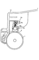
図13は感光ドラム7、帯電ローラ8、感光ドラム7と帯電ローラ8の第1の離間部材である第1のスペーサ部材60、トナーシールであるテアテープ52及びトナーシール把手53などの配置を示すものである。
【0033】
帯電ローラ8は芯金8aの回りに導電性のゴム部材8dを成形して構成されており、軸受8cを介して加圧ばね(付勢部材)8bによって感光ドラム7に押し付けられている。スペーサ部材60はトナーシール把手53と同一側面の芯金8aと感光ドラム7表面との間に挟み込むようにして挿入され、帯電ローラ8を傾けて変位させ、感光ドラム7表面から離間させている(図13参照)。
【0034】
一方、トナーシール把手53はトナー枠体11と一体成形されて、トナー枠体11とつながる部分を特に薄くして切り離せるようにしてあり、テアテープ52の端部52aがこのトナーシール把手53に貼り付けてある。なお、トナーシール把手53はトナー枠体11と別体に構成し、トナー枠体11の側面に穿設し孔(不図示)などと緩く嵌合する係止部を持つように構成してもよい。
【0035】
スペーサ部材60はトナーシール把手53と、たとえば弾性シートで形成された第1の連結部材61と両面テープなどを用いて結合されている。すなわち、トナーシール把手53とスペーサ部材60とが結合されていることによって、ユーザーがトナーシール51を開封する際に、帯電ローラ8の離間部材であるスペーサ部材60が同時に除去されるため、スペーサ部材60の取り忘れが生じる可能性が少なくなる。また、これを実現するための構成も非常に簡単なものとすることができる。
【0036】
図15において、前述の発明に係る画像形成装置と同様な構成・作用の部材等については同じ符号を付してその説明は省略するものとする。
【0037】
図15は感光ドラム7、帯電ローラ8、テアテープ52、トナーシール把手53の配置を示すものである。ここで、トナーシール把手53の係止部53aは感光ドラム7と帯電ローラ8を離間させるだけの厚さを持ったスペーサ部材として、感光ドラム7と帯電ローラ8の間に挿入される。すなわち、トナーシール把手53の係止部53aが感光ドラム7と帯電ローラ8の離間部材を兼ねることにより、部品点数を増やすことなく、感光ドラム7と帯電ローラ8を離間させることができ、その解除に関しては複雑な機構を設けることなく、ユーザの操作により容易に行うことができる。
【0038】
〈実施の形態1〉
図16〜図19を参照して、発明の実施の形態1を説明する。
【0039】
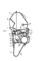
図16は感光ドラム7、帯電ローラ8、現像ローラ9c、現像枠体12、感光ドラム7と帯電ローラ8との第1の離間部材である第1のスペーサ部材70a、感光ドラム7と現像ローラ9cとの第2の離間部材である第2のスペーサ部材70bの配置を示すものである。
【0040】
帯電ローラ8は、芯金8aの回りに導電性のゴム部材8dを成形して構成されており、軸受8cを介して加圧ばね8bによって感光ドラム7に押し付けられている。
【0041】
第1の離間部材であるスペーサ部材70aは、帯電ローラ8の長手方向の両端部において芯金8aと感光ドラム7表面との間に挟み込むようにして挿入されて、帯電ローラ8を感光ドラム7表面から離間させている(図16、図19参照)。
【0042】
一方、芯金9c1 とこれを囲繞する弾性部材9c2 とを有する現像ローラ9cは、現像枠体12に対して回転自在に支持されており、現像枠体12を含む現像ユニットDは前述したように、クリーニングユニットCとは回動可能に結合されている。このため、現像枠体12と感光ドラム7とで挟み込むように第2のスペーサ部材70bを現像ローラ9cの両端部において、芯金9c1 と感光ドラム7表面との間に挿入することにより、現像ローラ9cを感光ドラム7表面から離間させている(図16、図19参照)。
【0043】
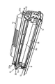
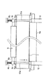
図17に示すように、第1、第2のスペーサ部材70a、70bを、例えば弾性シートで形成された第2の連結部材61aと両面テープなどを用いて結合し、さらに第2のスペーサ部材70bとカートリッジ枠体外部に引き出されたスペーサ把手部材62とを、弾性シートで形成された第3の連結部材61bと両面テープなどを用いて結合する。なお、第1、第2のスペーサ部材70a、70bと第2、第3の連結部材61a、62bとスペーサ把手部材62とは一体で成形された一部品で構成するようにしてもよい。
【0044】
すなわち、2つの第1、第2のスペーサ部材70a、70bとスペーサ把手部材62とが第2、第3の連結部材61a、61bで連結されていることで、これらをスペーサ把手部材62方向へ引き抜くことにより、2つの第1、第2のスペーサ部材70a、70bを一つの動作で同時に除去することができる。
【0045】
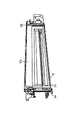
また、第1のスペーサ部材70aの感光ドラム7の半径方向の寸法(以下「厚さ」という。)W1は、帯電ローラ8のゴム部材8dの半径と芯金8aの半径との差g1より大きく、稼動時の感光ドラム7表面と現像枠体12との間隙g2より小さく、かつ第2のスペーサ部材70bの厚さW2は、稼動時の感光ドラム7表面と現像枠体12と間隙g2より大きく構成されている(図17、図18参照)。すなわち、このような寸法の大小関係が成り立っていることにより、スペーサ部材引き抜き方向に関して、上流側に位置する第1のスペーサ部材70aの引き抜きを現像枠体12などと干渉することなくスムーズに行うことが可能となる。
【0046】
さらに図16に示すように、第1、第2のスペーサ部材70a、70bのそれぞれ帯電ローラ接触面、現像枠体接触面には、スペーサ部材解除方向に平行な方向に細かい溝71a、71bが設けられている。一方、現像枠体12の長手方向でスペーサ部材70a、70bに相当する位置には、上述の溝71a、71bと嵌合するスペーサ部材ガイド用のリブ(規制部材)12gが設けてある。すなわち、スペーサ部材70a、70bの溝71a、71bとガイド用リブ12gとを嵌合させることにより、スペーサ部材70a、70bを解除する際に、感光ドラム7の長手方向に横滑りなどすることなく確実に解除することができる。なお、ガイド用リブ12gはクリーニング枠体に設けられていても同様の効果が得られる。
【0047】
【発明の効果】
以上説明したように、本発明によると、第1の離間部材は、把手部材をカートリッジ枠体から引き抜くことでシール部材を破砕して現像剤収納部の開口部を開口させる動作に連動して、第1の連結部材を介して第1の離間部材を引き抜いて前記帯電ローラを前記像担持体表面に当接させることができる。したがって、第1の離間部材を引き抜くための特別な動作は不要であり、ユーザへの負担が増加することはない。
【図面の簡単な説明】
【図1】実施の形態の画像形成装置の概略構成を示す縦断面図。
【図2】実施の形態の画像形成装置の外観を示す斜視図。
【図3】実施の形態のプロセスカートリッジの縦断面図。
【図4】実施の形態のプロセスカートリッジの右側上方から見た外観斜視図。
【図5】実施の形態のプロセスカートリッジの右側面図。
【図6】実施の形態のプロセスカートリッジの左側面図。
【図7】実施の形態におけるクリーニングユニットの斜視図。
【図8】実施の形態における現像ユニットの斜視図。
【図9】実施の形態における現像枠体の斜視図。
【図10】実施の形態におけるトナー枠体の斜視図。
【図11】実施の形態におけるトナー枠体の斜視図。
【図12】実施の形態における帯電ローラの支持部の構成を示す図。
【図13】実施の形態における、帯電ローラと感光ドラムとの離間の状態を示す正面図。
【図14】実施の形態における、帯電ローラと感光ドラムとの当接の状態を示す正面図。
【図15】実施の形態における、帯電ローラと感光ドラムとの離間の状態を示す正面図。
【図16】実施の形態1における、帯電ローラ及び現像ローラと感光ドラムとの離間の状態を示す縦断面図。
【図17】実施の形態1における、第1、第2の離間部材及び第2、第3の連結部材の、上面図及び側面図。
【図18】実施の形態1における、帯電ローラ及び現像ローラと感光ドラムとの当接の状態を示す縦断面図。
【図19】実施の形態1における、帯電ローラ及び現像ローラと感光ドラムとの当接の状態を示す正面図。
【符号の説明】
7 像担持体(感光ドラム)
8 帯電部材(帯電ローラ)
8a 帯電ローラの小径部(芯金)
8b 付勢部材(加圧ばね)
8d 帯電ローラの大径部(ゴム部材)
9 現像装置
9c1 現像ローラ小径部
11A 現像剤収納部(トナー容器)
11i 開口部
12g 規制部材(リブ)
14 画像形成装置本体
51 シール部材(カバーフィルム)
52 シール部材(テアテープ)
53 把手部材(トナーシール把手)
53a 係止部
60 第1の離間部材(第1のスペーサ部材)
61 第1の連結部材
61a 第2の連結部材
61b 第3の連結部材
70a 第1の離間部材(第1のスペーサ部材)
70b 第2の離間部材(第2のスペーサ部材)
71a、71b 溝
A 画像形成装置
B プロセスカートリッジ
g1 帯電ローラの大径部の半径と小径部の半径との差
g2 カートリッジ枠体及び現像ローラの小径部と感光ドラム表面との間隙
W1 第1の離間部材の像担持体半径方向の寸法(第1の離間部材の厚さ)
W2 第2の離間部材の像担持体半径方向の寸法(第2の離間部材の厚さ)
Y カートリッジ枠体(ハウジング)[0001]
BACKGROUND OF THE INVENTION
The present invention relates to a process cartridge and an image forming apparatus used for a copying machine, a laser printer, a facsimile, and the like.
[0002]
[Prior art]
Image forming apparatuses such as copiers, laser printers, and facsimile machines selectively expose a photosensitive drum (image carrier) uniformly charged by a charging device to form an electrostatic latent image. The image is developed as a toner image by attaching toner with a developing device, and then the toner image is transferred to a recording material such as paper to form an image. Then, the toner remaining on the surface of the photosensitive drum after the transfer of the toner image is removed by a cleaning device and used for the next image formation.
[0003]
In recent years, there has been known a cartridge in which a photosensitive drum, a charging device, a developing device, a cleaning device, and the like are integrated into a cartridge container to form a process cartridge. Since the process cartridge is configured to be detachable from the image forming apparatus main body, the user can easily supply the toner and replace the photosensitive drum by the user by attaching the process cartridge to the image forming apparatus main body. It is possible to make maintenance easier.
[0004]
Further, in recent years, independent developing devices for yellow, magenta, cyan, and black are selectively disposed on the photosensitive drum to perform a developing operation, or are fixedly disposed on the photosensitive drum and are respectively disposed. An image forming apparatus for forming a multicolor image by selectively driving a developing device has been devised, and a process cartridge used for the multicolor image forming apparatus has been put into practical use.
[0005]
Here, as the charging device in the above-described process cartridge, a non-contact method using corona discharge or the like and a contact method using a charging roller or the like are generally used. Contact methods are becoming more commonly used.
[0006]
[Problems to be solved by the invention]
However, if the above-mentioned contact-type charging device is left in contact with the photosensitive drum for a long time, the portion of the charging member (for example, charging roller) that contacts the photosensitive drum is permanently deformed. In some cases, the charging ability is changed to cause image defects such as density unevenness. Also, on the surface of the photosensitive drum, the photosensitive drum and the charging member rub against each other due to vibration or the like when the process cartridge is transported, and a history remains as a charging memory, which may cause image defects such as density unevenness.
[0007]
As a solution to these problems, a spacer member is conventionally sandwiched between the photosensitive drum surface and the charging member, and in particular, an area outside the area where the image is written (image forming area) (non-image forming area). A method of holding the two in a separated state (particularly during transport) (Japanese Patent Laid-Open No. 2-39169), a method of applying pressure and separation using a solenoid (Japanese Patent Laid-Open No. 3-48879), and the like However, according to these methods, when the process cartridge is used, the user has to contact the charging roller with the photosensitive drum, which increases the burden on the user, and a mechanism for pressurizing / separating. However, there was a problem that it was complicated and costly.
[0008]
The present invention has been made in view of the above-described circumstances, and a simple configuration and burden on the user to remove the spacer member that separates the charging roller from the photosensitive drum in order to prevent image defects such as image unevenness. It is an object of the present invention to provide a process cartridge and an image forming apparatus which can be performed with a simple operation without applying the above.
[0009]
[Means for Solving the Problems]
In order to achieve the above-mentioned object, the present invention according to
[0014]
According to a second aspect of the present invention, in the process cartridge according to the first aspect , a groove is formed in the upstream separating member in parallel with the pulling direction, and a wall-shaped regulating member that engages with the groove is formed on the cartridge frame. It is provided.
[0015]
The present invention according to
[0016]
DETAILED DESCRIPTION OF THE INVENTION
Hereinafter, embodiments of the present invention will be described with reference to the drawings.
[0017]
< Embodiment >
FIG. 1 shows an example of an image forming apparatus according to the invention. The image forming apparatus shown in the figure is an electrophotographic laser beam printer, and the figure is a longitudinal sectional view showing a schematic configuration thereof.
[0018]
A laser beam printer (hereinafter referred to as “image forming apparatus”) A shown at the same time forms an image on a recording material (for example, paper, an OHP sheet, cloth, etc.) by an electrophotographic process, and has a drum shape as an image carrier. The electrophotographic photosensitive member (hereinafter referred to as “photosensitive drum”) 7 is provided.
[0019]
The
[0020]
The above-described
[0021]
Further, the feeding /
[0022]
The fixing
[0023]
Next, the process cartridge B according to the present invention will be described.
[0024]
As shown in FIG. 3 (longitudinal sectional view), FIG. 4 (right upper perspective view), FIG. 5 (right side view), and FIG. 6 (left side view), the process cartridge B has a toner container (developer). A cleaning frame 10 having a
[0025]
[Cartridge frame configuration]
Next, the configuration of the housing Y of the process cartridge B according to the present embodiment will be described.
[0026]
In the process cartridge B shown in the present embodiment, a
[0027]
As shown in FIGS. 3 and 10, a
[0028]
Further, as shown in FIGS. 3 and 10, the
[0029]
The developing unit D and the cleaning unit C described above are coupled to each other by a round
[0030]
[Toner seal configuration]
As shown in FIG. 11, in the longitudinal direction of the
[0031]
Next, details of the characteristic portion of the present invention will be described with reference to FIGS.
[0032]
FIG. 13 shows the arrangement of the
[0033]
The charging
[0034]
On the other hand, the toner seal handle 53 is formed integrally with the
[0035]
The
[0036]
In FIG. 15, members and the like having the same configurations and functions as those of the image forming apparatus according to the above-described invention are denoted by the same reference numerals and description thereof is omitted.
[0037]
FIG. 15 shows the arrangement of the
[0038]
<
A first embodiment of the invention will be described with reference to FIGS.
[0039]
FIG. 16 shows the
[0040]
The charging
[0041]
The
[0042]
On the other hand, the developing
[0043]
As shown in FIG. 17, the first and
[0044]
That is, since the two first and
[0045]
Further, the radial dimension (hereinafter referred to as “thickness”) W1 of the
[0046]
Further, as shown in FIG. 16,
[0047]
【The invention's effect】
As described above, according to the present invention, the first separation member is interlocked with the operation of crushing the seal member by pulling out the handle member from the cartridge frame and opening the opening of the developer storage portion. The charging roller can be brought into contact with the surface of the image carrier by pulling out the first separation member via the first connecting member. Therefore, a special operation for pulling out the first separation member is unnecessary, and the burden on the user does not increase.
[Brief description of the drawings]
Figure 1 is a longitudinal sectional view showing a schematic configuration of an image forming apparatus in the form status of implementation.
Figure 2 is a perspective view showing an appearance of an image forming apparatus in the form status of implementation.
Figure 3 is a longitudinal sectional view of the process cartridge in the form status of implementation.
Figure 4 is an external perspective view from the right side above the process cartridge in the form status of implementation.
[5] a right side view of the process cartridge in the form status of implementation.
[6] a left side view of the process cartridge in the form status of implementation.
Figure 7 is a perspective view of the cleaning unit definitive to form state implementation.
Figure 8 is a perspective view of the definitive development unit in the form status of implementation.
Figure 9 is a perspective view of the developing device frame for definitive to form state implementation.
Figure 10 is a perspective view of a toner frame for definitive to form state implementation.
Figure 11 is a perspective view of a toner frame for definitive to form state implementation.
12 is a diagram showing a structure of a support part of the definitive charging roller in the form status of implementation.
[13] definitive in the form status of implementation, front view showing a spaced state between the charging roller and the photosensitive drum.
[14] definitive in the form status of implementation, front view showing a state of the contact between the charging roller and the photosensitive drum.
[15] definitive in the form status of implementation, front view showing a spaced state between the charging roller and the photosensitive drum.
[16] in the form state first embodiment, longitudinal sectional view showing a separated state between the charging roller and the developing roller and the photosensitive drum.
In Figure 17 form state first embodiment, the first, second separating member and the second, third connecting member, top and side views.
[18] in the form state first embodiment, longitudinal sectional view showing the state of contact between the charging roller and the developing roller and the photosensitive drum.
[19] in the form state first embodiment, a front view showing the contact state between the charging roller and the developing roller and the photosensitive drum.
[Explanation of symbols]
7 Image carrier (photosensitive drum)
8 Charging member (charging roller)
8a Small diameter part of the charging roller (core metal)
8b Energizing member (pressure spring)
8d Large diameter part of charging roller (rubber member)
9 Developing
14 Image forming
52 Sealing member (Tear tape)
53 Handle member (toner seal handle)
61
70b Second separation member (second spacer member)
71a, 71b Groove A Image forming apparatus B Process cartridge g1 Difference between the radius of the large diameter portion and the small diameter portion of the charging roller g2 The gap W1 between the cartridge frame and the small diameter portions of the developing roller and the photosensitive drum surface First separation Dimension of image carrier in radial direction of member (thickness of first separating member)
W2 Dimensions of the second spacing member in the radial direction of the image carrier (thickness of the second spacing member)
Y Cartridge frame (housing)
Claims (3)
前記像担持体表面に向けて前記帯電ローラを付勢する付勢部材と、
前記付勢部材の付勢力に抗して前記帯電ローラの軸と前記像担持体との間に挿入されて前記像担持体表面から前記帯電ローラを離間させる第1の離間部材と、
前記現像ローラと前記像担持体との間に挿入されて前記像担持体表面から前記現像ローラを離間させる第2の離間部材と、
前記第1の離間部材と前記第2の離間部材とを連結する連結部材と、を備え、
前記連結部材を介して連結した前記第1の離間部材と前記第2の離間部材とを前記像担持体の周方向に沿って前記カートリッジ枠体から引き抜くことで前記現像ローラを前記像担持体表面に当接させるとともに前記帯電ローラを前記像担持体表面に当接させ、
前記第1の離間部材と前記第2の離間部材のうち、引き抜き方向の上流側に存在する離間部材を上流側離間部材として、
前記上流側離間部材の前記像担持体半径方向の寸法は、前記帯電ローラ又は現像ローラのうち引き抜き方向の下流側に存在するローラと、前記像担持体とが接触した状態において、当該ローラの軸と前記像担持体との間を通過可能な大きさに設定され、且つ、
前記上流側離間部材は、前記上流側離間部材の引き抜き経路上の前記カートリッジ枠体と前記像担持体表面との間を干渉することなく引き抜き可能に設定される、
ことを特徴とするプロセスカートリッジ。An image bearing member, a charging roller that charges the surface of the image bearing member, and a developing roller, and a developing device that develops the toner image by attaching toner to an electrostatic latent image formed on the surface of the image bearing member. In a detachable process cartridge that is integrally incorporated in a cartridge frame and is attached to the image forming apparatus main body.
A biasing member for biasing the charging roller towards the surface of the image bearing member,
A first separating member for separating the charging roller from the inserted to the image bearing member surface between the shaft and said image bearing member of the charging roller against the urging force of the pre-Symbol urging member,
A second spacing member inserted between the developing roller and the image carrier to separate the developing roller from the surface of the image carrier;
A connecting member that connects the first spacing member and the second spacing member ;
The developing roller is removed from the surface of the image carrier by pulling out the first and second spacers connected via the connecting member from the cartridge frame along the circumferential direction of the image carrier. And the charging roller is brought into contact with the surface of the image carrier,
Among the first spacing member and the second spacing member, a spacing member existing on the upstream side in the drawing direction is used as an upstream spacing member.
The size of the upstream carrier member in the radial direction of the image carrier is such that the roller on the downstream side in the drawing direction of the charging roller or the developing roller and the image carrier are in contact with each other. And a size capable of passing between the image carrier and the image carrier, and
The upstream side separation member is set so that it can be pulled out without interfering between the cartridge frame on the drawing path of the upstream side separation member and the surface of the image carrier.
A process cartridge characterized by that.
ことを特徴とする請求項1に記載のプロセスカートリッジ。 A groove is provided in the upstream separation member in parallel with the pulling direction, and a wall-shaped regulation member that engages with the groove is provided in the cartridge frame.
The process cartridge according to claim 1 .
前記プロセスカートリッジが請求項1又は2に記載のプロセスカートリッジである、
ことを特徴とする画像形成装置。 In an image forming apparatus comprising: an image forming apparatus main body; and a detachable process cartridge that is attached to the image forming apparatus main body and used.
The process cartridge is the process cartridge according to claim 1 or 2 .
An image forming apparatus.
Priority Applications (1)
| Application Number | Priority Date | Filing Date | Title |
|---|---|---|---|
| JP2000009478A JP4136245B2 (en) | 2000-01-18 | 2000-01-18 | Process cartridge and image forming apparatus |
Applications Claiming Priority (1)
| Application Number | Priority Date | Filing Date | Title |
|---|---|---|---|
| JP2000009478A JP4136245B2 (en) | 2000-01-18 | 2000-01-18 | Process cartridge and image forming apparatus |
Publications (3)
| Publication Number | Publication Date |
|---|---|
| JP2001201914A JP2001201914A (en) | 2001-07-27 |
| JP2001201914A5 JP2001201914A5 (en) | 2005-07-28 |
| JP4136245B2 true JP4136245B2 (en) | 2008-08-20 |
Family
ID=18537626
Family Applications (1)
| Application Number | Title | Priority Date | Filing Date |
|---|---|---|---|
| JP2000009478A Expired - Fee Related JP4136245B2 (en) | 2000-01-18 | 2000-01-18 | Process cartridge and image forming apparatus |
Country Status (1)
| Country | Link |
|---|---|
| JP (1) | JP4136245B2 (en) |
Families Citing this family (16)
| Publication number | Priority date | Publication date | Assignee | Title |
|---|---|---|---|---|
| US7072603B2 (en) | 2003-08-01 | 2006-07-04 | Canon Kabushiki Kaisha | Process cartridge and holding member |
| JP4585889B2 (en) * | 2004-03-22 | 2010-11-24 | キヤノン株式会社 | Developing device and image forming apparatus |
| US20060008289A1 (en) | 2004-07-06 | 2006-01-12 | Canon Kabushiki Kaisha | Electrophotographic image forming apparatus and process cartridge |
| JP2006171031A (en) * | 2004-12-10 | 2006-06-29 | Ricoh Co Ltd | Mark member, unit and image forming apparatus |
| KR100633070B1 (en) * | 2004-12-14 | 2006-10-11 | 삼성전자주식회사 | Developing apparatus |
| JP4684732B2 (en) * | 2005-04-27 | 2011-05-18 | キヤノン株式会社 | Electrophotographic image forming apparatus and process cartridge |
| JP2007148117A (en) * | 2005-11-29 | 2007-06-14 | Canon Inc | Electrophotographic image forming apparatus |
| JP4537960B2 (en) * | 2006-01-24 | 2010-09-08 | 株式会社沖データ | Separating member and image forming apparatus having the separating member |
| JP4788439B2 (en) | 2006-03-30 | 2011-10-05 | 富士ゼロックス株式会社 | Image carrier unit and image forming apparatus |
| JP4797874B2 (en) * | 2006-08-10 | 2011-10-19 | 富士ゼロックス株式会社 | Toner cartridge and image forming apparatus using the same |
| JP2008304643A (en) | 2007-06-06 | 2008-12-18 | Ricoh Co Ltd | Removable member and unit |
| JP2011186378A (en) | 2010-03-11 | 2011-09-22 | Canon Inc | Process cartridge and image forming device |
| JP2011232434A (en) * | 2010-04-26 | 2011-11-17 | Canon Inc | Process cartridge and image forming device |
| JP5539038B2 (en) | 2010-06-02 | 2014-07-02 | キヤノン株式会社 | Electrophotographic image forming apparatus |
| JP4685197B2 (en) * | 2010-10-29 | 2011-05-18 | キヤノン株式会社 | Electrophotographic image forming apparatus and process cartridge |
| JP5257529B2 (en) * | 2012-04-11 | 2013-08-07 | 株式会社リコー | Unused unit and removal member |
-
2000
- 2000-01-18 JP JP2000009478A patent/JP4136245B2/en not_active Expired - Fee Related
Also Published As
| Publication number | Publication date |
|---|---|
| JP2001201914A (en) | 2001-07-27 |
Similar Documents
| Publication | Publication Date | Title |
|---|---|---|
| US7272339B2 (en) | Process cartridge including first and second frames and separating member moving the second frame to a separated position and image forming apparatus detachably mounting the cartridge | |
| JP4136245B2 (en) | Process cartridge and image forming apparatus | |
| JP6140962B2 (en) | Cartridge, process cartridge, and image forming apparatus | |
| JP5145839B2 (en) | Fixing apparatus and image forming apparatus | |
| JP3630957B2 (en) | Development device | |
| JP2005316192A (en) | Electrophotographic image forming apparatus | |
| JP2005099517A (en) | Process cartridge and electrophotographic image forming apparatus | |
| US9731918B2 (en) | Roller separation device and image forming apparatus using the same | |
| JP5344599B2 (en) | Image forming apparatus | |
| JP2011232434A (en) | Process cartridge and image forming device | |
| JP4617197B2 (en) | Electrophotographic photosensitive drum, process cartridge, electrophotographic image forming apparatus, and method of assembling flange of electrophotographic photosensitive drum | |
| JP6137786B2 (en) | Developing device, process cartridge, image forming apparatus | |
| JP2001194866A (en) | Pressure means of electrifying roller and image forming device equipped therewith | |
| JP4967648B2 (en) | Image forming apparatus | |
| JP6039247B2 (en) | Developing device, process cartridge, image forming apparatus | |
| KR100644710B1 (en) | Image forming apparatus including means for feeding printable medium | |
| JP3839986B2 (en) | Developing device, process cartridge, and electrophotographic image forming apparatus | |
| JP4568354B2 (en) | Sheet transport device | |
| JP2006337725A (en) | Process cartridge and electrophotographic image forming apparatus | |
| JP3984978B2 (en) | Process cartridge and electrophotographic image forming apparatus | |
| JPH1130944A (en) | Process cartridge unit and attaching/detaching structure thereof | |
| JP2001194977A (en) | Process cartridge and image forming device | |
| JP2001201915A (en) | Process cartridge and image forming device | |
| US10474059B2 (en) | Developing unit and process cartridge | |
| JP5370922B2 (en) | Developing device, process unit, image forming apparatus, and assembling method of developing device |
Legal Events
| Date | Code | Title | Description |
|---|---|---|---|
| A521 | Written amendment |
Free format text: JAPANESE INTERMEDIATE CODE: A523 Effective date: 20041214 |
|
| A621 | Written request for application examination |
Free format text: JAPANESE INTERMEDIATE CODE: A621 Effective date: 20041214 |
|
| A977 | Report on retrieval |
Free format text: JAPANESE INTERMEDIATE CODE: A971007 Effective date: 20071225 |
|
| A131 | Notification of reasons for refusal |
Free format text: JAPANESE INTERMEDIATE CODE: A131 Effective date: 20080226 |
|
| A521 | Written amendment |
Free format text: JAPANESE INTERMEDIATE CODE: A523 Effective date: 20080423 |
|
| TRDD | Decision of grant or rejection written | ||
| A01 | Written decision to grant a patent or to grant a registration (utility model) |
Free format text: JAPANESE INTERMEDIATE CODE: A01 Effective date: 20080520 |
|
| A01 | Written decision to grant a patent or to grant a registration (utility model) |
Free format text: JAPANESE INTERMEDIATE CODE: A01 |
|
| A61 | First payment of annual fees (during grant procedure) |
Free format text: JAPANESE INTERMEDIATE CODE: A61 Effective date: 20080603 |
|
| R150 | Certificate of patent or registration of utility model |
Free format text: JAPANESE INTERMEDIATE CODE: R150 |
|
| FPAY | Renewal fee payment (event date is renewal date of database) |
Free format text: PAYMENT UNTIL: 20110613 Year of fee payment: 3 |
|
| FPAY | Renewal fee payment (event date is renewal date of database) |
Free format text: PAYMENT UNTIL: 20120613 Year of fee payment: 4 |
|
| FPAY | Renewal fee payment (event date is renewal date of database) |
Free format text: PAYMENT UNTIL: 20120613 Year of fee payment: 4 |
|
| FPAY | Renewal fee payment (event date is renewal date of database) |
Free format text: PAYMENT UNTIL: 20130613 Year of fee payment: 5 |
|
| LAPS | Cancellation because of no payment of annual fees |