JP4136125B2 - Print positioning method and printing apparatus - Google Patents
Print positioning method and printing apparatus Download PDFInfo
- Publication number
- JP4136125B2 JP4136125B2 JP30619098A JP30619098A JP4136125B2 JP 4136125 B2 JP4136125 B2 JP 4136125B2 JP 30619098 A JP30619098 A JP 30619098A JP 30619098 A JP30619098 A JP 30619098A JP 4136125 B2 JP4136125 B2 JP 4136125B2
- Authority
- JP
- Japan
- Prior art keywords
- dot
- printing
- pattern
- adjustment
- Prior art date
- Legal status (The legal status is an assumption and is not a legal conclusion. Google has not performed a legal analysis and makes no representation as to the accuracy of the status listed.)
- Expired - Fee Related
Links
Images


Classifications
-
- B—PERFORMING OPERATIONS; TRANSPORTING
- B41—PRINTING; LINING MACHINES; TYPEWRITERS; STAMPS
- B41J—TYPEWRITERS; SELECTIVE PRINTING MECHANISMS, i.e. MECHANISMS PRINTING OTHERWISE THAN FROM A FORME; CORRECTION OF TYPOGRAPHICAL ERRORS
- B41J2/00—Typewriters or selective printing mechanisms characterised by the printing or marking process for which they are designed
- B41J2/005—Typewriters or selective printing mechanisms characterised by the printing or marking process for which they are designed characterised by bringing liquid or particles selectively into contact with a printing material
- B41J2/01—Ink jet
- B41J2/21—Ink jet for multi-colour printing
- B41J2/2132—Print quality control characterised by dot disposition, e.g. for reducing white stripes or banding
- B41J2/2135—Alignment of dots
Description
【0001】
【発明の属する技術分野】
本発明は、ドットマトリックス記録におけるドット形成位置の調整方法および該方法を用いたプリント装置に関し、例えば往走査と副走査と双方向でプリントを行う場合のドット位置合わせや、複数のプリントヘッドを用いてプリントを行う場合のヘッド間のプリント位置合せに適用できるドット形成位置の調整方法および該方法を用いたプリント装置に関する。
【0002】
【背景技術】
近年、比較的低廉なパーソナルコンピュータやワードプロセッサ等のOA機器が広く普及しており、これら機器で入力した情報をプリントアウトする様々な記録装置や該装置の高速化技術、高画質化技術が急速に開発されてきている。記録装置の中でも、ドットマトリクス記録(プリント)方法を用いたシリアルプリンタは、低コストで高速ないしは高画質のプリントを実現する記録装置(プリント装置)として着目されている。かかるプリンタに対して、高速度のプリントを行う技術としては例えば双方向プリント方法があり、また高画質のプリントを行う技術としては例えばマルチパスなどがある。
【0003】
(双方向プリント方法)
高速化技術としては、複数のプリント素子を有するプリントヘッドにおいてプリント素子数の増加やプリントヘッドの走査速度の向上等を図ることも考えられているが、プリントヘッドの往復双方向のプリント走査を行うことも1つの有効な方法である。
【0004】
プリント装置では通常、給紙・排紙等の時間があるため単純な比例関係にはならないが、双方向プリントは片方向プリントに比べて約2倍のプリント速度を得ることができる。
【0005】
例えば、プリント密度が360dpiでプリント走査(主走査)方向とは異なる方向(例えばプリント媒体の送り方向である副走査方向)に64個の吐出口を配列したプリントヘッドを用い、A4サイズのプリント媒体を縦向きにしてプリントを行う場合、約60回のプリント走査でプリントを完了することができるが、片方向プリントでは当該プリント走査がすべて所定の走査開始位置から一方向への移動時にのみ行われ、かつ走査終了位置から走査開始位置へ復帰するための逆方向への非プリント走査を伴うので、約60回の往復が行われるものとなる。これに対し双方向プリントでは約30回の往復プリント走査でプリントが完成し、約2倍に近い速度でプリントを行うことが可能となるので、プリント速度の向上には有効な方法であるといえる。
【0006】
かかる双方向プリントを行うためには、往路と復路とのドット形成位置(例えばインクジェットプリント装置にあってはインクドットの着弾位置)を合わせるために、エンコーダ等の位置検出手段を用い、当該検出位置に基づいてプリントタイミングを制御することが多い。しかしこのようなフィードバック制御系を構成することはプリント装置のコスト増の要因ともなるので、比較的低廉なプリント装置でこれを実現するのは困難であると考えられていた。
【0007】
(マルチ走査プリント方法)
次に、高画質化技術の一例として、マルチ走査プリント方法について説明する。
【0008】
複数のプリント素子を有するプリントヘッドを用いてプリントを行う場合、プリントされる画像の品位はプリントヘッド単体の性能に依存するところが大きい。例えばインクジェットプリントヘッドの場合、インク吐出口の形状や、電気熱変換体(吐出ヒータ)などインク吐出に利用されるエネルギを発生するための素子のバラツキ等、プリントヘッド製造工程で生じる僅かな違いが、それぞれ吐出されるインクの吐出量や吐出方向の向きに影響を及ぼし、最終的に形成される画像の濃度ムラとして画像品位を低下させる原因となりうる。
【0009】
図1および図2を用いてその具体例を説明する。図1の(A)において、201はプリントヘッドであり、簡単のため8個のノズル(本明細書では、特にことわらない限り吐出口ないしこれに連通する液路およびインク吐出に利用されるエネルギを発生する素子を総括して言うものとする)202によって構成されているものとする。203はノズル202よって例えば滴として吐出されたインクであり、通常はこの図のように各吐出口からほぼ均一な吐出量で、かつ揃った方向にインクが吐出されるのが理想である。もし、このような吐出が行われれば、図1の(B)に示したようにプリント媒体上に揃った大きさのインクドットが着弾し、図1の(C)に示すように全体的にも濃度ムラの無い一様な画像が得られるのである。
【0010】
しかし、実際にはプリントヘッド201は先にも述べたように1つ1つのノズルにはそれぞれバラツキがあり、そのまま上記と同じようにプリントを行ってしまうと、図2の(A)に示したようにそれぞれのノズルより吐出されるインク滴の大きさおよび向きにバラツキが生じ、プリント媒体上に図の2(B)に示すように着弾する。この図によれば、ヘッド主走査方向に対し、周期的にエリアファクタが100%に満たない白紙の部分が存在したり、また逆に必要以上にドットが重なり合ったり、あるいはこの図中央に見られるような白筋が発生したりしている。この様な状態で着弾されたドットの集まりはノズル並び方向に対し、図2の(C)に示した濃度分布となり、結果的には、通常人間の目でみた限りでこれらの現象が濃度ムラとして感知される。
【0011】
そこでこの濃度ムラ対策として次のような方法が考案されている。図3および図4によりその方法を説明する。
【0012】
この方法では、図1および図2で示したのと同様の領域についてのプリントを完成させるのにプリントヘッド201を図3の(A)および図4(A)〜(C)に示すように3回スキャンしているが、図中縦方向8画素の半分である4画素を単位とする領域は2パスで完成している。この場合プリントヘッドの8ノズルは、図中上半分の4ノズルと、下半分の4ノズルとのグループに分けられ、1ノズルが1回のスキャンで形成するドットは、画像データをある所定の画像データ配列に従って約半分に間引いたものである。そして2回目のスキャン時に残りの半分の画像データへドットを埋め込み、4画素単位の領域を完成させて行く。以上のようなプリント方法を以下マルチ走査プリント方法と称す。
【0013】
このようなプリント方法を用いると、図2で示したプリントヘッド201と等しいヘッド201を使用しても、各ノズルのばらつきによるプリント画像への影響が半減されるので、プリントされた画像は図3の(B)のようになり、図2の(B)に見るような黒スジや白スジが余り目立たなくなる。従って濃度ムラも図3の(C)に示すように図2の場合と比べ、かなり緩和される。
【0014】
このようなプリントを行う際、1スキャン目と2スキャン目とでは、画像データをある決まった配列(マスク)に従い、互いに埋め合わせる形で分割するが、通常この画像データ配列(間引きパターン)とは、図4に示すように、縦横1画素毎に、丁度千鳥格子になるようなものを用いるのが最も一般的である。単位プリント領域(ここでは4画素単位)においては千鳥状にドットを形成する1スキャン目と、逆千鳥状にドットを形成する2スキャン目とによってプリントが完成されるものである。また、通常各走査間のプリント媒体の移動量(副走査量)は一定に設定されており、図3および図4の場合には、4ノズル分ずつ均等に移動させている。
【0015】
(ドットアライメント)
ドットマトリクスプリント方法における高画質化技術の他の例として、ドット着弾位置を調整するドットアライメント技術がある。ドットアライメントとは、プリント媒体上のドットが形成される位置を何らかの手段で調整する調整方法であり、従来のドットアライメントは、一般的には以下のように行われていた。
【0016】
例えば往復印字における、往走査と副走査の着弾位置合わせにおいては、往走査と副走査とでそれぞれプリントタイミングを調整することにより、往復走査での相対的なプリント位置条件を変えながら罫線等をプリント媒体上にプリントする。それをユーザが自ら目視し、最も位置の合っていると思われる条件、つまり罫線等がずれることなくプリントされている条件を選び出して、直接プリント装置にキー操作等で入力して設定するか、もしくはホストコンピュータを操作することによりアプリケーションを介して着弾位置条件をプリント装置に設定していた。
【0017】
また、複数ヘッドを有するプリント装置において、複数のヘッド間でプリントを行う場合は、複数のヘッド間での相対的なプリント位置条件を変えながら、それぞれのヘッドで罫線等を被プリント媒体上にプリントする。それを前述同ようにユーザがプリント位置の合っている最適な条件を選び、相対的なプリント位置条件を変え、それぞれのヘッド毎に、前述と同様の手段でプリント装置にプリント位置の条件を設定していた。
【0018】
【発明が解決しようとする課題】
ここで、ドットの着弾位置のズレを生じてしまった場合について説明する。
【0019】
(双方向プリントにより画像形成を行う上での問題点)
双方向プリントに対しては以下のような問題を引き起こしてしまう。
【0020】
まず、プリントヘッドの主走査方向に垂直な方向の罫線(縦罫線)をプリントする場合、往路でプリントする罫線と復路でプリントする罫線との間で位置が合わずに、罫線が直線にならずに段差が生じてしまう。これは所謂「罫線ズレ」と称されているものであるが、一般的なユーザが認識する最も一般的な画像の乱れであると言える。罫線は黒色で形成される場合が多いので、一般的にモノクローム画像を形成する際の問題として認識されていたが、カラー画像でも同様の現象は起こるのである。
【0021】
(インク吐出量変調を伴う双方向プリントによる画像形成を行う上での問題点)インクジェットプリント装置の場合、プリントドットの大きさは主にプリントヘッドから吐出されるインク量で決定される。そこで、吐出量を比較的小としたインクドットを適宜用いてプリントを行えば高解像度を実現することができ、一方いわゆる「ベタ」プリントを行うような場合には、吐出量を比較的大としたインクドットでプリントを行えばプリント効率を向上することができる。
【0022】
一般に、プリントヘッドを走査せつつインクを例えば滴(ドロップ)として吐出してプリントを行うインクジェットプリント装置の場合、ドロップの着弾位置は走査速度成分の影響を受ける。また、吐出されるインク量が異なる場合には一般に吐出速度が異なり、例えば大小ドロップを混在させて用い、さらに双方向プリントにて画像形成を行うような場合には、大ドロップの双方向プリントについて最適なプリント位置条件を定めても、大ドロップに対する小ドロップのレジストレーションがずれてしまう。
【0023】
このようなずれが生じると、一様な中間調パターンをプリントした場合に全体的にざらついた印象を与えうる画像が形成され、ユーザによっては不快な模様として認識してしまうこともある。
【0024】
(複数ヘッドを用いて画像形成を行う上での問題点)
複数ヘッドを有するプリント装置において、複数のヘッド間でドットの着弾位置のズレを生じてしまった場合の問題について考える。
【0025】
画像プリントを行う場合、何種類かの色を組み合わせて画像形成を行うことが多く、最も多いのは、イエロー、マゼンタ、シアンの3原色にさらにブラックを加えた4色を用いるのが一般的である。これらの色をプリントするための複数のプリントヘッドを用いる場合において、プリントヘッド間で着弾位置のズレがあると、ずれ量にもよるが異なる色同士が同じ画素にプリントされると色ズレを起こしてしまう。例えば、青の画像を形成するのにマゼンタおよびシアンを用いるが、両色のドットが重なっている部分では青になるものの、重なっていない部分では青にはならずそれぞれの単独の色味が現れるという色ズレを生じてしまう。これが一部分で起きても目立つことはないが、この現象が走査方向に連続して発生してしまうと、ある特定の幅のバンド状の色ズレとなり、不均一な画像になってしまう。さらに、同じ色の画像でそれに隣接する領域において、ドットの着弾位置のズレがないと、隣接する画像領域間で均一感や発色が異なり、画像として違和感のあるものになってしまう。また、この色のズレは、普通紙ではさほど目立つことはないが、コート紙等の発色の良いプリント媒体を用いる場合に目立ってしまうことがある。
【0026】
また、異なる色を隣接する画素にプリントする場合、ドットの着弾位置のズレがあると、その部分に隙間すなわちインクにより覆われない領域が生じてしまい、プリント媒体の地が直接見えてしまうことがある。プリント媒体は一般的に白地のものが多いので、この現象は「白抜け」と呼ばれることが多い。この現象はコントラストの強い画像で目立ちやすく、有彩色をバックグラウンドとして黒画像を形成する場合等では、黒色と有彩色との間にインクのない白い隙間が存在することになり、白と黒との間のコントラストが強いため、よりはっきりと目立ってしまうことがある。
【0027】
(課題)
以上のような問題の発生を抑制するためには、前述のドットアライメントを行うのが有効である。しかしユーザが着弾位置合わせ条件を変化させたプリント結果を目視して、最適な着弾位置合わせ条件を選択し、入力作業を行わなければならないという煩雑さを伴い、また基本的に目視により最適なプリント位置を得るための判断をユーザに強いるために、最適ではない設定がなされてしてしまう場合もある。従って、操作に不慣れなユーザには特に不利である。
【0028】
また、ユーザは着弾位置合わせを行うための画像のプリントを行い、さらにこれを見て所要の判断を行った後に条件設定を行わなくてはならないため、ユーザに少なくとも2度の手間を掛けさせることになり、操作性のよい装置ないしシステムを実現する上で好ましくないばかりか、時間的にも不利なものとなる。
【0029】
すなわち、上述のような画像形成上の問題や操作性上の問題を発生させずに、高速で且つ高画質の画像のプリントを行いうる装置ないしシステムを、エンコーダ等のフィードバック制御手段を用いずオープンループで着弾位置を合わせることができるようにして低コストで実現することが強く望ましい。
【0030】
そこで、本発明は操作性に優れた低コストのドットアライメント方法を実現せんとするものである。また、本発明は、基本的にユーザに判断や調整を強いることなく、プリントした画像の光学的特性を検出して、当該検出結果より最適なドットアライメントの調整条件を算出して、調整条件の設定を自動的に行うことができるようになし、その調整精度を向上させることを目的としている。
【0031】
【課題を解決するための手段】
そのために、本発明は、1つのノズルから吐出するドットを少なくとも大小2段階に変調可能な複数のノズルを備えるプリントヘッドを用い、プリント媒体にドット形成位置を異ならせた往走査のプリントおよび復走査のプリントにより画像のプリントを行うプリント装置に対し、前記往走査および復走査のプリント間のドット形成位置のずれを調整してプリント位置合わせを行うための処理を行うプリント位置合わせ方法であって、
前記大小ドットの一方を用いて前記往走査のプリントおよび復走査のプリントにより形成されるパターンであって、当該往走査のプリントと当該復走査のプリントとの相対的なドット形成位置をそれぞれ異なるようにずらした複数のパターンを前記プリントヘッドに形成させるパターン形成工程と、
当該形成された複数のパターンに基づき、前記一方のドットについての前記ずれを調整するための調整値を得る調整値取得工程と、
前記大小ドットのうち他方の前記往走査および復走査のプリント間のドット形成位置のずれを調整するために、前記調整値に基づき前記他方のドットによる形成位置のずれを補正する補正工程と、を具え、
前記補正工程は、前記大小ドットのうち他方の、前記調整値を適用した場合の前記往走査のプリントによるドット形成位置に対する前記復走査のプリントによるドット形成位置の前記復走査の方向のずれ量が所定量以下の場合には、前記往走査においては先に前記小ドットから吐出を開始して次に前記大ドットの吐出が行われ、前記復走査においては前記大ドットから吐出を開始して次に前記小ドットの吐出が行われるように前記大小ドットの吐出順序を定め、
前記ずれ量が前記所定量より大きい場合には、前記往走査と復走査とで前記小ドットから吐出を開始して次に大ドットの吐出が行われるように前記大小ドットの吐出順序を等しくするとともに、かつ、前記大小ドットの吐出順序を等しくしたことによる、前記大小ドットそれぞれの、当該往走査のプリントによるドット形成位置に対する当該復走査のプリントによるドット形成位置の前記復走査の方向のずれ量の分だけ、当該復走査のプリントによる前記大小ドットの形成位置が前記復走査の方向と反対方向にシフトするように前記大ドットおよび前記小ドットの吐出タイミングを定めることを特徴とする。
【0032】
また、本発明は、1つのノズルから吐出するドットを少なくとも大小2段階に変調可能な複数のノズルを備えるプリントヘッドを用い、プリント媒体にドット形成位置を異ならせた往走査のプリントおよび復走査のプリントにより画像のプリントを行うプリント装置であって、
前記大小ドットの一方を用いて前記往走査のプリントおよび復走査のプリントにより形成されるパターンであって、当該往走査のプリントと当該復走査のプリントとの相対的なドット形成位置をそれぞれ異なるようにずらした複数のパターンを前記プリントヘッドに形成させるパターン形成手段と、
当該形成された複数のパターンに基づき、前記一方のドットについての前記往走査のプリントと前記復走査のプリントとの間のドット形成位置のずれを調整するための調整値を得る調整値取得手段と、
前記大小ドットのうち他方の前記往走査および復走査のプリント間のドット形成位置のずれを調整するために、前記調整値に基づき前記他方のドットによる形成位置のずれを補正する補正手段と、を具え、
前記補正手段は、前記大小ドットのうち他方の、前記調整値を適用した場合の前記往走査のプリントによるドット形成位置に対する前記復走査のプリントによるドット形成位置の前記復走査の方向のずれ量が所定量以下の場合には、前記往走査においては先に前記小ドットから吐出を開始して次に前記大ドットの吐出が行われ、前記復走査においては前記大ドットから吐出を開始して次に前記小ドットの吐出が行われるように前記大小ドットの吐出順序を定め、
前記ずれ量が前記所定量より大きい場合には、前記往走査と復走査とで前記小ドットから吐出を開始して次に大ドットの吐出が行われるように前記大小ドットの吐出順序を等しくするとともに、かつ、前記大小ドットの吐出順序を等しくしたことによる、前記大小ドットそれぞれの、当該往走査のプリントによるドット形成位置に対する当該復走査のプリントによるドット形成位置の前記復走査の方向のずれ量の分だけ、当該復走査のプリントによる前記大小ドットの形成位置が前記復走査の方向と反対方向にシフトするように前記大ドットおよび前記小ドットの吐出タイミングを定めることを特徴とする。
【0033】
さらに、本発明は、1つのノズルから吐出するドットを少なくとも大小2段階に変調可能な複数のノズルを備えるプリントヘッドを用い、プリント媒体にドット形成位置を異ならせた往走査のプリントおよび復走査のプリントにより画像のプリントを行うプリント装置と、該プリント装置に対して前記画像のデータを供給するホスト装置とを具備したプリントシステムであって、
前記大小ドットの一方を用いて前記往走査のプリントおよび復走査のプリントにより形成されるパターンであって、当該往走査のプリントと当該復走査のプリントとの相対的なドット形成位置をそれぞれ異なるようにずらした複数のパターンを前記プリントヘッドに形成させるパターン形成手段と、
当該形成された複数のパターンに基づき、前記一方のドットについての前記往走査のプリントと前記復走査のプリントとの間のドット形成位置のずれを調整するための調整値を得る調整値取得手段と、
前記大小ドットのうち他方の前記往走査および復走査のプリント間のドット形成位置のずれを調整するために、前記調整値に基づき前記他方のドットによる形成位置のずれ量を取得して形成位置のずれを補正する補正手段と、を具え、
前記補正手段は、前記大小ドットのうち他方の、前記調整値を適用した場合の前記往走査のプリントによるドット形成位置に対する前記復走査のプリントによるドット形成位置の前記復走査の方向のずれ量が所定量以下の場合には、前記往走査においては前記小ドットから形成を開始して次に前記大ドットが形成され、前記復走査においては先に前記小ドットから吐出を開始して次に前記大ドットの吐出が行われ、前記復走査においては前記大ドットから吐出を開始して次に前記小ドットの吐出が行われるように前記大小ドットの吐出順序を定め、
前記ずれ量が前記所定量より大きい場合には、前記往走査と復走査とで前記小ドットから吐出を開始して次に大ドットの吐出が行われるように前記大小ドットの吐出順序を等しくするとともに、かつ、前記大小ドットの吐出順序を等しくしたことによる、前記大小ドットそれぞれの、当該往走査のプリントによるドット形成位置に対する当該復走査のプリントによるドット形成位置の前記復走査の方向のずれ量の分だけ、当該復走査のプリントによる前記大小ドットの形成位置が前記復走査の方向と反対方向にシフトするように前記大ドットおよび前記小ドットの吐出タイミングを定めることを特徴とする。
【0034】
以上において、前記調整値取得工程または手段は、前記パターン形成工程または手段により形成された前記複数のパターンのそれぞれの光学特性を測定する工程または手段と、当該測定された複数のパターンそれぞれの光学特性に基づいて前記調整値を取得する工程または手段とを有するものとすることができる。
【0035】
また、前記パターン形成および前記調整値取得を複数回、異なるドット位置合わせ精度毎に実行させる工程または手段を具えることができる。
【0036】
ここで、前記パターン形成および前記調整値取得を複数回、異なるドット位置合わせ精度毎に実行させる工程または手段は、前記位置合わせ精度をドット単位の精度で行うための粗調整工程または手段と、1ドット以内の精度で行う微調整工程または手段とを含み、前記粗調整後に前記微調整を行うか、または前記微調整後に前記粗調整を行うことができる。
【0037】
前記パターン形成工程または手段は、前記往走査のプリントおよび復走査のプリントにより形成されるパターンであって、該往走査のプリントに対する前記復走査のプリントの相対的なドット形成位置のずらしの方向が異なる第1パターンおよび第2パターンを複数の前記ずらしの量に対応してそれぞれ複数形成し、前記調整値取得工程は、当該形成された前記複数の第1パターンのそれぞれの光学特性および前記複数の第2パターンのそれぞれの光学特性を測定し、当該測定された前記複数の第1パターンの光学特性の変化特性および前記複数の第2パターンの光学特性の変化特性の交点から、前記調整値を得ることができる。
【0038】
前記調整値取得工程または手段は、前記測定により得られた光学特性データより、直線近似または多項式近似を用いて、前記調整値を算出することができる。
【0042】
また、以上において、前記ずれ量を算出するための算出工程または手段を具え、前記プリントヘッドを吐出口からインクを吐出することによりプリントを行うヘッドとし、前記算出工程または手段は前記大小ドットを形成するためのそれぞれのインク吐出速度、前記プリントヘッドをプリント媒体に対して相対的に走査する走査速度、および前記吐出口から前記プリント媒体までの距離から前記算出を行うことができる。
【0044】
前記ヘッドは、インクを吐出するために利用されるエネルギとしてインクに膜沸騰を生じさせる熱エネルギを発生する発熱素子を有するものとすることができる。
【0045】
なお、本明細書において、「プリント」(以下においては「プリント」という場合もある)とは、文字、図形等有意の情報を形成する場合のみならず、有意無意を問わず、また人間が視覚で知覚し得るように顕在化したものであるか否かを問わず、広くプリント媒体上に画像、模様、パターン等を形成する、または媒体の加工を行う場合も言うものとする。
【0046】
ここで、「プリント媒体」とは、一般的なプリント装置で用いられる紙のみならず、広く、布、プラスチック・フィルム、金属板等、インクを受容可能な物も言うものとする。
【0047】
さらに、「インク」とは、上記「プリント」の定義と同様広く解釈されるべきもので、プリント媒体上に付与されることによって、画像、模様、パターン等の形成またはプリント媒体の加工に供され得る液体を言うものとする。
【0048】
【発明の実施の形態】
以下、図面を参照して本発明を詳細に説明する。なお、以下では本発明を主としてインクジェットプリント装置およびこれを用いるプリントシステムに適用した場合について説明する。
【0049】
1.概要
(1.1)ドットアライメント処理の概要
本発明の実施形態に係るドット形成位置(インク着弾位置)の調整(プリント位置合わせ)方法およびプリント装置では、相互にドット形成位置調整が行われるべき双方向プリントにおける往路のプリントおよび復路のプリント(それぞれ第1のプリントおよび第2のプリントに相当する)、もしくは複数(2個)のプリントヘッドによるそれぞれのプリント(第1 のプリント、第2のプリント)をプリント媒体上の同一の位置に行う。さらに、それを第1 のプリントと第2 のプリントとで相対的なドット形成位置の位置合わせ条件を変えて、複数条件下でプリントを行う。すなわち後述のプリントパターン(パッチ)を第1および第2プリントの相対的な位置条件を変え、複数個形成する。
【0050】
そして、キャリッジ等主走査部材に搭載された光学センサを用い、それらの濃度を読み取る。すなわちキャリッジ上の光学センサをパッチに対応した位置に移動し、その反射光学濃度(あるいは反射光の強度や反射率)を測定する。そしてそれらの値の相対関係から最も第1および第2プリントの位置があっている条件を判定する。すなわち着弾位置条件とその濃度の相対的な関係より着弾位置条件に対する濃度の近似特性を計算する。その近似特性より最適な着弾位置条件を求める。この際にプリントする画像パターンは、プリント装置およびプリントヘッドの持っている精度を考慮して設定する。第1のプリントにおいては、精度上から予測される着弾位置精度の最大ずれ量と同等もしくはそれ以上の幅を持っているパターンをプリント媒体にプリントする。第2のプリントは、同じ幅のパターンをそれぞれの着弾位置の位置合わせ条件でプリントする。これにより、着弾位置の位置合わせ条件の精度と同等もしくはそれ以上の精度で着弾位置条件を調整することができる。
【0051】
さらに、一旦設定した着弾位置条件を用い、相対的な着弾位置の位置合わせ条件を変えて、複数条件下で同ように第1のプリントおよび第2のプリントを行う。この場合の位置合わせ条件は、前回より高い精度で設定する。すなわち、1回目のドットアライメント(粗調整)により位置合わせを行った結果を踏まえ、当該合わせ込んだ精度を最大のずれと見込み、合わせ込んだ精度から予測される着弾位置精度の最大ずれ量と同等の幅を持っているパターンを用いて、第1のプリントと第2のプリントを行う。これにより、より高い精度でのドットアライメント(微調整)が可能となる。
【0052】
(1.2)全体のアルゴリズムの概要
光学センサのキャリブレーションを行ってから、粗調整を実施する。粗調整の調整範囲はプリント装置およびプリントヘッドの精度から決定する。粗調整で決定した着弾位置の位置合わせ条件を用いて、さらに微調整を行い、より高い精度でドットアライメントを実施する。微調整は粗調整で合わせた精度内で調整する。そのため、調整範囲は狭くできる分、調整間隔をより細かく設定することもできる。さらに、調整を終了した後にドットアライメントが正確に行われたか確認するべく確認パターンのプリントを行い、着弾位置が正確に制御されているかをユーザが確認できるようにしている。
【0053】
なお、ドットアライメントの実施範囲は、装置構成や装置の持つプリントのモード等に応じて適宜定めることができる。例えば、複数のプリントヘッドを用いるプリント装置では双方向プリントおよび複数ヘッド間プリントのドットアライメントを実施し、1つのヘッドのみを用いるプリント装置では双方向プリントのドットアライメントを実施すればよい。また、1つのヘッドでも、異なった色調(色、濃度)のインクを吐出可能な場合や、異なった吐出量を得ることができる場合は、それぞれの色調もしくはそれぞれの吐出量毎にドットアライメントを実施しても良い。
【0054】
さらに、後述するように、粗調整と微調整とは必ずしも上述の順序で行われなくてもよい。
【0055】
(1.3)確認パターンについて
ドットアライメントを行った後に、その制御が確実に行われたかを確認するために、もしくはドットアライメントの結果をユーザが認識できるようにするために、設定した着弾位置条件を用いて、確認パターンをプリントする。通常、罫線パターンが認識しやすいので、双方向プリント、複数ヘッド間等のそれぞれのモードにおいて、またそれぞれのプリント速度毎に、罫線のプリントを行う。これにより、ユーザは実施したドットアライメントの結果を一目瞭然に認識することができる。
【0056】
(1.4)光学センサについて
実施形態で使用する光学センサは、プリント装置で用いるインク色調やヘッド構成等に応じて適切に選択された発色のものを用いることができる。換言すれば、例えば赤色LEDもしくは赤外線LEDの発色に対して光の吸収特性に優れている色を用い、当該色インクに対応したプリント手段をドットアライメントの対象とする。吸収特性の点からは、ブラック(Bk)またはシアン(C)が好ましく、マゼンタ(M)やイエロー(Y)では十分な濃度特性,S/N比を得ることはできない。このように、用いるLEDの特性に応じて使用する色を決めることにより、各色に対応させることができる。例えば、赤色以外に青色LED、緑色LED等を搭載することで、Bkに対して各色(C、M、Y)毎にドットアライメントを行うことができる。
【0057】
(1.5)マニュアル調整について
実施形態では光学センサを用いて濃度の検出を行った上で自動のドットアライメント処理を実施するようにしている。しかし、光学センサが好ましく動作しない場合等にも備えて、その他のドットアライメント処理を可能とする。すなわちこの場合は、通常のマニュアル調整を実施する。かかるマニュアル調整に移行する条件について説明する。
【0058】
まず、光学センサを使用するにあたってキャリブレーションを行うが、その際得られたデータが明らかに使用可能範囲外のものである場合には、キャリブレーション・エラーとし、ドットアライメント動作を中止する。その状態のステータスをホストコンピュータに通信して、アプリケーションを介してエラーであることを表示する。さらに、マニュアル調整を実施するように表示して実行を促す。または、キャリブレーション・エラーを検知した場合ドットアライメント動作を中止して、給紙されているプリント媒体上にマニュアル調整の実施を促すプリントを行っても良い。
【0059】
次に、外乱について説明する。
【0060】
光学センサは、外部からの光の入射によっては誤動作してしまう場合がある。従って、ドットアライメントの最中に、極端に反射光が強くなった場合には外乱光があるものとし、ドットアライメントを中止する。そして、キャリブレーションエラーと同ようにその状態のステータスをホストコンピュータに通信して、アプリケーションを介してエラーであることを表示する。さらに、マニュアル調整を実施するように表示して実行を促す。または、キャリブレーションエラーを検知した場合ドットアライメント動作を中止して、給紙されているプリント媒体上にマニュアル調整の実施を促すプリントを行っても良い。
【0061】
もっとも、センサエラーが偶然の外乱光の入射のように一過性であるような場合には、時間を置いたり、あるいは条件を整えるようユーザに報知する等した上で再度ドットアライメント処理を起動するようにすることもできる。また、後述するモードその他に対応した各種プリント位置合わせ処理の一つの実行中にエラーが生じたような場合には、当該処理を中止して他のプリント位置合わせ処理を行うこともできる。
【0062】
(1.6)回復動作について
実施形態で採用している回復動作について説明する。これは、自動ドットアライメントを実行する前に、吸引・ワイピング・予備吐出など、プリントヘッドのインク吐出状態を良好にする、または良好に保持するための一連の回復動作を必ず行うようにしているものである。
【0063】
動作タイミングとしては、自動ドットアライメントの実行命令があった場合に、それを実行する前に回復動作を行なう。これにより、プリントヘッドの吐出状態が安定した状態でプリント位置合わせのためのパターンをプリントすることができ、より信頼性の高いプリント位置合わせの補正条件の設定が可能となる。
【0064】
回復動作としては吸引・ワイピング・予備吐出という一連の動作にのみ限定されず、予備吐出または予備吐出とワイピングだけでも良い。この場合の予備吐出はプリントの際の予備吐出よりも発数の多い予備吐出を行うように設定するのが好ましい。また、吸引、ワイピング、予備吐出の回数や動作順序といった組み合わせについても特に限定させるものではない。
【0065】
また、前回の吸引回復からの経過時間に応じて自動ドットアライメント制御前の吸引回復の実行の要否を判断しても良い。この場合、まず自動ドットアライメントを行う直前に前回の吸引動作から所定時間が経過したどうかを判定する。そして、所定時間以内に吸引動作が実施されていたなら、自動ドットアライメントレジを実施する。一方、所定時間以内に吸引回復動が実施されていなければ、吸引回復を含んだ一連の回復動作を実施した後に自動ドットアライメントを行うようにすることができる。
【0066】
また、前回の吸引回復からプリントヘッドが所定の吐出数以上のインク吐出を行ったか否かを判定するようにし、所定の吐出数以上のインク吐出を行っている場合には回復動作を実行してから自動ドットアライメントを実施するようにしても良いし、さらには経過時間とインク吐出数との双方を判断材料として、いずれかが所定値に達していたら吸引回復を実施するように組み合わせても良い。
【0067】
このようにすることで、吸引回復を過剰に実施することを防止することができるので、インクの消費量の節約および廃インク処理部へのインク排出量の低減に資することができるとともに、自動ドットアライメント前の回復動作を効率的に行うことができる。
【0068】
また、前回の吸引回復からの経過時間、もしくはインク吐出数に応じて回復条件を可変にし、例えば経過時間が短い場合には吸引動作をさせずに予備吐出とワイピングとのみを行い、経過時間が長い場合にはさらに吸引回復を介挿するというように回復条件を変更するようにしても良い。
【0069】
2.プリント装置の構成例
(2.1)機械的構成
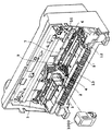
図5は、本発明が実施もしくは適用されて好適なカラーインクジェットプリント装置の構成例を示す斜視図であり、図においてはそのフロントカバーを取り外して装置内部を露出させた状態を示している。
【0070】
図において、1000は交換式のヘッドカートリッジ、2はそのインクジェットカートリッジを着脱自在に保持するキャリッジユニットである。3はインクジェットカートリッジ1000をキャリッジユニット2に固定するためのホルダであり、インクジェットカートリッジ1000をキャリッジユニット2内に装着してからカートリッジ固定レバー4を操作すると、これに連動してインクジェットカートリッジ1000をキャリッジユニット2に圧接する。また、当該圧接によってインクジェットカートリッジ1000の位置決めが行われると同時に、キャリッジユニット2に設けられた所要の信号伝達用の電気接点とインクジェットカートリッジ1側の電気接点とのコンタクトが行われる。5は電気信号をキャリッジユニット2に伝えるためのフレキシブルケーブルである。また、図5には示されていないが、反射型光学センサ30がキャリッジに設けられている。
【0071】
6はキャリッジユニット2を主走査方向に往復移動させるための駆動源をなすキャリッジモータ、7は当該駆動力をキャリッジユニット2に伝達するキャリッジベルトである。8′は主走査方向に延在してキャリッジユニット2の支持を行うとともにその移動を案内するガイドシャフトである。9はキャリッジユニット2に取り付けられた透過型のフォトカプラ、10はキャリッジホームポジション付近に設けられた遮光板であり、キャリッジユニット2がホームポジションに至ったときに遮光板10がフォトカプラ9の光軸を遮ることにより、キャリッジホームポジションの検出が行われる。12はインクジェットヘッドの前面をキャップするキャップ部材やこのキャップ内を吸引する吸引手段、さらにはヘッド前面のワイピングを行う部材などの回復系を含むホームポジションユニットである。
【0072】
13はプリント媒体を排出するための排出ローラであり、不図示の拍車状ローラと協動してプリント媒体を挟み込み、これをプリント装置外へと排出する。14はラインフィードユニットであり、プリント媒体を副操作方向へ所定量搬送する。
【0073】
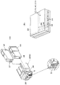
図6(A)は本例で用いたヘッドカートリッジ1000の詳細を示す斜視図である。ここで、15はブラックのインクを収納したインクタンク、16はシアン、マゼンタおよびイエローのインクを収納したインクタンクであり、これらはインクジェットカートリッジ本体に対して着脱できるようになっている。17はインクタンク16が収納する各色インクのインクジェットカートリッジ本体側のインク供給管20に対する連結口、18は同じくインクタンク15が収納するブラックインクの連結口であり、当該連結によってインクジェットカートリッジ本体に保持されているプリントヘッド1に対してインクの供給が可能となる。19は電気接点部であり、キャリッジユニット2に設けられた電気接点部とのコンタクトに伴ってフレキシブルケーブルを介しプリント装置本体制御部から電気信号の受容が可能となる。
【0074】
本例にあっては、Bkのインクを吐出するノズルを配列したBkインク吐出部と、それぞれY、MおよびCのインクを吐出するノズル群を一体かつインラインにBkの吐出口配列範囲に対応して配列してなるカラーインク吐出部とが並置されたヘッドを用いている。
【0075】
図6(B)は、ヘッドカートリッジ1000のプリントヘッド部1の主要部構造を部分的に示す模式的斜視図である。
【0076】
図6(B)において、プリント媒体8と所定の隙間(例えば約0.5〜2.0mm程度)をおいて対面する吐出口面21には、所定のピッチで複数の吐出口22が形成され、共通液室23と各吐出口22とを連通する各液路24の壁面に沿ってインク吐出の利用されるエネルギを発生するための電気熱変換体(発熱抵抗体など)25が配設されている。本例においては、ヘッドカートリッジ1000は、吐出口22がキャリッジ2の走査方向と交差する方向に並ぶような位置関係でキャリッジ2に搭載されている。こうして、画像信号または吐出信号に基づいて対応する電気熱変換体(以下においては、「吐出ヒータ」ともいう)25を駆動(通電)して、液路24内のインクを膜沸騰させ、そのときに発生する気泡の圧力によって吐出口22からインクを吐出させるプリントヘッド1が構成される。
【0077】
本例では1つのプリントヘッド内にBkインクを吐出するノズル群とY、M、Cのインクを吐出するノズル群が並置されている構成について述べたが、この形態に限定されるものではなく、Bkインクを吐出するノズル群のあるプリントヘッドとY、M、Cのインクを吐出するノズル群のあるプリントヘッドとが独立していても良いし、さらにはヘッドカートリッジが独立していても良い。また、各色のノズル群が独立している構成のヘッドカートリッジでも良いのである。プリントヘッド、ヘッドカートリッジの組み合わせに特に限定されるものではない。
【0078】
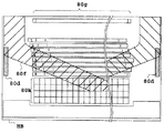
図7は本例で使用しているヘッドのヒータボードHBの模式図を示している。ヘッドの温度を制御するための温調用(サブ)ヒータ80d、インクを吐出させるための吐出用(メイン)ヒータ80cが配された吐出部列80g、駆動素子80hが同図で示されるような位置関係で同一基板上に形成されている。ヒータボード基体は通常Siウェハのチップであり、この上に同一の半導体成膜プロセスにて各ヒータや所要の駆動部が形成される。このように各素子を同一基板上に配することでヘッド温度の検出、制御が効率よく行え、さらにヘッドのコンパクト化、製造工程の簡略化を図ることができる。
【0079】
また同図には、特にBkインク用吐出部のヒータボードがインクで満たされる領域と、そうでない領域とに分離する天板の外周壁断面80fの位置関係を示している。この天板の外周壁断面80fの吐出用ヒータ80d側が共通液室として機能する。なお、天板の外周壁断面80fの吐出部列80g上に形成された複数の溝部によって複数の液路が形成される。Y,M,Cのカラーインク吐出部についてもほぼ同様の構成であるが、各インク用の供給液室ないし天板を適切に構成することにより、異なる色のインクの混合が生じないよう分離もしくは区画が行われる。
【0080】
図8は、図5の装置に用いられる反射型光学センサ30を説明するための模式図である。
【0081】
図8に示すように、反射型光学センサ30は上述したようにキャリッジ2に取り付けられ、発光部31と受光部32を有するものである。発光部31から発した光Iin35はプリント媒体8で反射し、その反射光Iref37を受光部32で検出することができる。そしてその検出信号はフレキシブルケーブル(不図示)を介してプリント装置の電気基板上に形成される制御回路に伝えられ、そのA/D変換器によりディジタル信号に変換される。光学センサ30がキャリッジ2に取付けられる位置は、インク等の飛沫の付着を防ぐため、プリント走査時にプリントヘッド1の吐出口部が通過する部分を通らない位置としてある。このセンサ30は比較的低解像度のものを用いることができるため、低コストのもので済む。
【0082】
(2.2)制御系の構成
次に、上述した装置のプリント制御を実行するための制御系の構成について説明する。
【0083】
図9は当該制御系の構成の一例を示すブロック図である。同図において、コントローラ100は主制御部であり、例えばマイクロコンピュータ形態のMPU101、プログラムや所要のテーブルその他の固定データを格納したROM103、後述のドットアライメント処理によって得られ、実際のプリント時においてプリント位置合わせに用いられる調整データ(後述の各モード毎に得られるものでもよい)を格納するためのEEPROMなどの不揮発性メモリ107、各種データ(上記プリント信号やヘッドに供給されるプリントデータ等)を保存しておくダイナミック型のRAM105等を有する。このRAM105にはプリントドット数や、インクプリントヘッドの交換回数等も記憶させておくことができる。104はプリントヘッド1に対するプリントデータの供給制御を行うゲートアレイであり、インタフェース112、MPU101、RAM1105間のデータの転送制御も行う。ホスト装置110は、画像データの供給源(プリントに係る画像等のデータの作成、処理等を行うコンピュータとする他、画像読み取り用のリーダ部等の形態であってもよい)である。画像データ、その他のコマンド、ステータス信号等は、インタフェース(I/F)112を介してコントローラ100と送受信される。
【0084】
操作部820は操作者による指示入力を受容するスイッチ群であり、電源スイッチ122、プリント開始を指示するためのスイッチ124、吸引回復の起動を指示するための回復スイッチ126、レジストレーションを起動するためのレジストレーション調整起動スイッチ127、マニュアルで該調整値を入力するためのレジストレーション調整値設定入力部129等を有する。
【0085】
センサ群130は装置の状態を検出するためのセンサ群であり、上述の反射型光学センサ30、ホームポジションを検出するためのフォトカプラ132および環境温度を検出するために適宜の部位に設けられた温度センサ134等を有する。
【0086】
ヘッドドライバ150は、プリントデータ等に応じてプリントヘッド1の吐出ヒータ25を駆動するドライバであり、ドット形成位置合わせのために駆動タイミング(吐出タイミング)を適切に設定するタイミング設定部等を有する。151は主走査モータ4を駆動するドライバ、162はプリント媒体8を搬送(副走査)するために用いられるモータ、160はそのドライバである。
【0087】
図10は、図9の各部の詳細を示す回路図の一例である。ゲートアレイ104は、データラッチ141、セグメント(SEG)シフトレジスタ142、マルチプレクサ(MPX)143、コモン(COM)タイミング発生回路144、デコーダ145を有する。プリントヘッド1は、ダイオードマトリックス構成を取っており、コモン信号COMとセグメント信号SEGが一致したところの吐出用ヒータ(H1からH64)に駆動電流が流れ、これによりインクが加熱され吐出する。
【0088】
デコーダ145は、コモンタイミング発生回路144が発生したタイミングをデコードして、コモン信号COM1〜COM8のいずれか1つを選択する。データラッチ141はRAM105から読み出されたプリントデータを8ビット単位でラッチし、このプリントデータをマルチプレクサ143はセグメントシフトレジスタ142に従い、セグメント信号SEG1〜SEG8として出力する。マルチプレクサ143からの出力は、後述するように1ビット単位、2ビット単位、または8ビット全てなど、シフトレジスタ142の内容によって種々変更することができる。
【0089】
上記制御構成の動作を説明すると、インターフェース112にプリント信号が入るとゲートアレイ104とMPU101との間でプリント信号がプリント用のプリントデータに変換される。そして、モータドライバ151、160が駆動されるとともに、ヘッドドライバ150に送られたプリントデータに従ってプリントヘッドが駆動されプリントが行われる。なお、ここでは64ノズルのプリントヘッドを駆動する場合について説明してきたが、他のノズル数でも同ような構成で駆動制御できる。
【0090】
次に、図11を用いてプリント装置内部でのプリントデータの流れを説明する。ホストコンピュータ110から送られたプリントデータはインターフェース112を介してプリント装置内部の受信バッファRBに蓄えられる。受信バッファRBは数k〜数十kバイトの容量を持っている。受信バッファRBに蓄えられたプリントデータに対してコマンド解析が行われてからテキストバッファTBへ送られる。
【0091】
テキストバッファTB中では一行分の中間形式としてプリントデータが保持され、各文字等のプリント位置、修飾の種類、大きさ、文字(コード)、フォントのアドレス等が付加される処理が行われる。テキストバッファTBの容量は各機種毎により異なり、シリアルプリンタであれば数行分の容量、ページプリンタであれば1ページ分の容量を持っている。さらにテキストバッファTBに蓄えられたプリントデータを展開してプリントバッファPBに2値化された状態で蓄え、プリントヘッドにプリントデータとして信号を送り、プリントが行われる。
【0092】
本例ではプリントバッファPBに蓄えられている2値化データに特定の割合の間引きマスクパターンを掛けてからプリントヘッドに信号を送るようにしている。そのため、プリントバッファPBに蓄えられている状態のデータを見てからマスクパターンを設定することもできる。プリント装置の種類によってはテキストバッファTBを有することなく、受信バッファRBに蓄積したプリントデータをコマンド解析と同時に展開してプリントバッファPBに書き込むものもある。
【0093】
図12はデータ転送回路の構成例を示すブロック図でありかかる回路はコントローラ100の一部として設けておくことができる。同図において171はメモリデータバスに接続され、メモリ中のプリントバッファに蓄えられているプリントデータを読み出して一時的に格納するためのデータレジスタ、172はデータレジスタ171に格納されたデータをシリアルデータに変換するためのパラレル−シリアル変換器、173はシリアルデータにマスクをかけるためのANDゲート、174はデータ転送数を管理するためのカウンタである。
【0094】
175はMPUデータバスに接続され、マスクパターンを格納するためのレジスタ、176はマスクパターンの桁位置を選択するためのセレクタ、177はマスクパターンの行位置を選択するためのセレクタである。
【0095】
図12に示すデータ転送回路はMPU101から送られるプリント信号により、プリントヘッド1に128ビットのプリントデータをシリアル転送する。メモリ中のプリントバッファPBに蓄えられていたプリントデータはデータレジスタ171に一時的に格納され、パラレル−シリアル変換器172によってシリアルデータに変換される。変換されたシリアルデータはANDゲート103によってマスクをかけられた後、プリントヘッド1に転送される。転送カウンタ174は転送ビット数をカウントして128に達したらデータ転送を終了させる。
【0096】
マスクレジスタ175は4本のマスクレジスタA、B、C、Dより構成され、MPUによって書き込まれたマスクパターンを格納する。各レジスタは縦4ビット×横4ビットのマスクパターンを格納する。セレクタ176はカラムカウンタ181の値を選択信号とすることによって桁位置に対応したマスクパターンデータを選択する。またセレクタ177は転送カウンタ174の値を選択信号とすることによって行位置に対応したマスクパターンデータを選択する。セレクタ176、177によって選択されたマスクパターンデータにより、ANDゲート173を用いて転送データにマスクがかけられる。
【0097】
なお、この例では4つのマスクレジスタ構成で説明したが、これは他のマスクレジスタ数であってもよい。また、この例ではマスクされた転送データは直接プリントヘッド1に供給したが、一旦プリントバッファに格納するようにしてもよい。
【0098】
3.ドットアライメント(プリント位置合わせ)の態様
次に、本実施形態の基本となるプリント位置合わせの態様について説明する。
【0099】
(3.1)双方向プリントでのプリント位置合わせ
図13(A)〜(C)は双方向プリントでのプリント位置合わせにおけるプリントパターンの例を示す模式図である。
【0100】
図13(A)〜(C)において、白抜きのドット700は往走査(第1プリント)でプリント媒体上に形成するドット、ハッチングを施したドット710は復走査(第2プリント)で形成するドットを示す。図13(A)〜(C)においては説明のためドットハッチングの有無をつけているが、各ドットは本実施形態では同一のプリントヘッドから吐出されるインクで形成したドットであり、ドットの色ないし濃さに対応したものでない。
【0101】
図13(A)は往走査と復走査でプリント位置が合っている状態でプリントした場合のドットを示しており、(B)はプリント位置が少しずれた状態、(C)はプリント位置がさらにずれた状態でプリントしたときのドットを示している。なお、これらの図13(A)〜(C)からも明らかなように、本実施の形態では往復走査それぞれで相補的なドット形成を行うものである。すなわち、往走査では奇数番目の列のドットを形成し、復走査では偶数番目の列のドットを形成する。従って、往復それぞれのドットが互いに略1ドットの直径分の距離を有する図13(A)の場合がプリント位置が合った状態となる。
【0102】
このプリントパターンは、プリント位置がずれるのに従ってプリント部全体の濃度が低下するように設計されている。すなわち、図13(A)のプリントパターンとしてのパッチの範囲内では、エリアファクタは略100%である。図13(B)、(C)に示すようにプリント位置がずれるに従い、往走査のドット(白抜きドット)と復走査のドット(ハッチ付ドット)の重なりが大きくなるとともに、プリントされていない領域、すなわちドットによって覆われていない領域も広がる。この結果、エリアファクタが低下するので、平均すれば全体的な濃度は減少する。
【0103】
本実施の形態ではプリントタイミングをずらすことにより、プリント位置をずらしている。これはプリントデータ上でずらしても可能である。
【0104】
図13(A)〜(C)では走査方向に1ドット単位で示しているが、レジストレーション(プリント位置合わせ)の精度またはレジストレーション検出の精度等に応じて、適宜の単位を設定することができる。図14(A)〜(C)は、4ドット単位の場合を示し、(A)はプリント位置が合っている状態、(B)は少しずれた状態、(C)はさらにずれた状態でプリントされたときのドットの状態である。
【0105】
これらのパターンの意図するところは、往復のプリント位置が相互にずれるのに対してエリアファクタが減少するようにすることである。それはプリント部の濃度はエリアファクタの変化に強く依存するからである。すなわちドットが重なることにより濃度は上昇するが、プリントされていない領域の増加の方が、プリント部全体の平均的濃度に与える影響が大きいからである。
【0106】
図15は、本実施の形態の図13(A)〜(C)、図14(A)〜(C)に示すプリントパターンにおいてプリント位置のずれる量と反射光学濃度の変化の関係の概略を示す。
【0107】
図15において、縦軸は反射光学濃度(OD値)であり、横軸はプリント位置のずれの量(μm)である。図7の入射光Iin35、反射光Iref37を用いると、反射率R=Iref/Iinであり、透過率T=1−Rである。光学濃度には、反射率Rを用いた反射光学濃度と透過率Tを用いた透過光学濃度があるが、本明細書においては反射光学濃度を用い、特に混乱の無い限り、光学濃度または単に濃度と省略する。
【0108】
反射光学濃度をdとすると、R=10-dという関係がある。プリント位置のずれの量が0であるときにエリア・ファクタが100%となるから、反射率Rは最も小さくなる。すなわち反射光学濃度dが最大となる。プリント位置が+−のいずれの方向に相対的にずれても、反射光学濃度dは減少していく。
【0109】
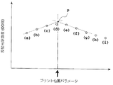
図16は、プリント位置合わせの処理の概略のフローチャートを示す。
【0110】
図16に示すように、まず所定のプリントパターンをプリントする(ステップS1)。次に、光学センサ30でこのプリントパターンの光学特性を測定する(ステップS2)。測定したデータから得た光学的特性に基づいて、適切なプリント位置条件を求める(ステップS3)。例えば、図18(後述)のように、最も反射光学濃度の高いポイントを求めて、最も反射光学濃度の高いポイントの両隣りのデータを通る各直線を最小自乗法等を用いて求め、これらの直線の交点Pを求める。このような直線近似による他、図18(後述)に示すように、曲線近似により求めることもできる。いずれにしても、この点Pに対するプリント位置パラメータにより、駆動タイミングの変更を設定する(ステップS4)。
【0111】
図17は、図13(A)〜(C)または図14(A)〜(C)に示すプリントパターンをプリント媒体8にプリントした状態を示す。本実施の形態では、往走査と復走査との間の相対的な位置ずれ量の異なる9通りのパターン61〜69をプリントする。プリントされた各パターンをパッチともいい、例えばパッチ61、62等とも称する。パッチ61〜69に対応するプリント位置パラメータを各々(a)〜(i)と表す。この9通りのパターン61〜69は、例えば往走査と復走査のプリント開始タイミングについて、往走査の方を固定とする。一方、復走査の開始タイミングについては現在設定されている開始タイミングと、それより早い4段階のタイミング、それより遅い4段階のタイミングの計9通りのタイミングそれぞれでプリントされる。このような図16の処理手順およびそれに基づく9通りのパターン61〜69のプリントは、後述する全体アルゴリズムにおける処理の一部として位置づけることができる。
【0112】
このようにプリントされたプリントパターンとしてのパッチ60等に対して、キャリッジ2に搭載された光学センサ30が対応した位置にくるように、プリント媒体8およびキャリッジ2を移動させ、キャリッジ2が静止した状態でそれぞれのパッチ60等について光学特性を測定する。本例の場合、光学特性としては反射光学濃度または透過光学濃度を用いる。しかし、光学反射率や反射光強度等を用いても良い。このように、キャリッジ2が静止した状態で測定することにより、キャリッジ2の駆動によるノイズの影響を避けることができる。また光学センサ30の測定スポットのサイズを、例えばセンサ30とプリント媒体8との距離を大きくすることによって、ドット径に対し広くすることにより、プリントされたパターン上の局所的な光学特性(例えば反射光学濃度)のばらつきを平均化して、精度の高いパッチ60等の反射光学濃度の測定を行うことができる。
【0113】
光学センサ30の測定スポットを相対的に広くする構成として、パターンのプリント解像度よりも低い解像度のセンサ、すなわちドット径より大きい測定スポット径を有するセンサを用いることが望ましい。しかし、平均濃度を求めるという観点から比較的解像度の高いセンサ、すなわち小さい測定スポット径を有するセンサでパッチ上を複数ポイントにわたり走査し、そのようにして得られた濃度の平均を測定濃度として用いてもよい。
【0114】
すなわち、測定ばらつきの影響を避けるために、複数回の同じパッチの反射光学濃度の測定を行い平均を取った値を採用しても良い。
【0115】
パッチ内の濃度ムラによる測定バラツキの影響を避けるためにも、パッチ内の複数ポイント測定して平均化、もしくは何らかの演算処理を施してもよい。時間削減のためキャリッジ2を移動させながら測定することも可能である。この場合にはモーター駆動による電気的なノイズによる測定バラツキを避けるためにもサンプリング回数を増やして平均化、もしくは何らかの演算処理を施すことが強く望ましい。
【0116】
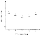
図18は、測定した反射光学濃度のデータの例を模式的に示す。
【0117】
図18において、縦軸は反射光学濃度であり、横軸は往走査と復走査の相対的なプリント位置を変えるための印字位置パラメーターである。この印字位置パラメータは、上述したように往走査に対する復走査のプリント開始タイミングを早くしたり遅くしたりするパラメータとすることができる。
【0118】
図18に示す測定結果を得た場合、本実施の形態では、最も反射光学濃度が高いポイント(図18中、プリント位置パラメータ(d)に対応するポイント)の、両隣りのそれぞれ2つのポイント(図18中のプリント位置パラメータ(b)、(c)と(e)、(f)に各々対応するポイント)を通るそれぞれの直線が交差した点Pを、最もプリント位置が合っているポイントと判断する。そして、この点Pに対応するプリント位置パラメータにより、本実施の形態の場合、対応する復走査のプリント開始タイミングを設定する。しかし、厳密なプリント位置合わせが望まれない場合またはそれが不要である場合には、プリント位置パラメータ(d)を用いてもよい。
【0119】
図18に示すように、この方法によれば、プリントパターン61等をプリントするのに用いたプリントピッチ等のプリント位置合わせ条件より細かい条件のピッチ、あるいは高い解像度でプリント位置合わせ条件を選択することができる。
【0120】
図18において、プリント位置パラメータ(c)、(d)、(e)に対応する濃度の高いポイントの間は、プリント位置合わせ条件の違いに対して濃度は大きく変わらない。それに対し、プリント位置パラメータ(a)、(b)、(c)に対応するポイントの間、プリント位置パラメータ(f)、(g)、(h)、(i)に対応するポイントの間は、プリント位置合わせ条件の変化に対し濃度は敏感に変化する。本実施の形態のように左右対称に近い濃度の特性を示す場合には、これらプリント位置合わせ条件に対し敏感な濃度変化を示すポイントを用いて、プリントに用いるプリント位置合わせ条件を算出することにより、より高精度にプリント位置を合わせることができる。
【0121】
プリント位置合わせ条件の算出方法はこの方法に限ったものではない。これらの複数の多値の濃度データと、パターンプリントに用いたプリント位置合わせ条件の情報に基づいて数値計算を行い、パターンプリントに用いたプリント位置合わせ条件の離散的な値以上の精度で、プリント位置合わせ条件を算出するのも本発明の意図するところの一つである。
【0122】
例えば、図18に示すような直線近似以外の例として、これらの濃度データをプリントに用いて、複数のプリント位置合わせ条件に対する最小二乗法を用いた多項式の近似式を得て、その式を用いて最もプリント位置の合う条件を算出してもよい。また、多項式近似に限らず、スプライン補間等を用いてもよい。
【0123】
最終的なプリント位置合わせ条件を、パターンプリントに用いた複数のプリント位置合わせ条件から選ぶ場合でも、上記のような複数の多値データを用いた数値計算よりプリント位置合わせ条件を算出することにより、各種データのばらつきに対しより高精度にプリント位置合わせることができる。例えば、図11のデータより最も濃度の高いポイントを選ぶやり方をすると、ばらつきにより、プリント位置パラメータ(d)に対応するポイントより(e)に対応するポイントの方が濃度が高い場合があり得る。そこで、最も濃度の高いポイントの両側の各3つのポイントにより近似直線を求めて交点を算出するやり方をすると、3つ以上のポイントのデータを使い計算することにより、ばらつきの影響を減少することができる。
【0124】
次に、図11で示した位置合わせ条件の算出方法とは別の例を説明する。
【0125】
図19は、測定した光学反射率のデータの例を示す。
【0126】
図19において、縦軸は光学反射率であり、横軸は往走査と復走査の相対的なプリント位置を変えるためのプリント位置パラメータ(a)〜(i)である。例えば復走査のプリントするタイミングを早くしたり、遅くしたりしてプリント位置を変えるものがこれに相当する。本例では、測定したデータより各パッチにおける代表点を決めて、これらの代表点から全体の近似曲線を求め、その近似曲線の最小点をプリント位置一致ポイントと判断する。
【0127】
以上では、図17に示したような複数のプリント位置合わせ条件について、それぞれ離れた正方形あるいは長方形のパターン(パッチ)をプリントしたが、その構成に限るものではない。それぞれのプリント位置合わせ条件に対する濃度測定を行うことができるエリアがあればよいのであって、例えば図17の複数のプリントパターン(パッチ61等)が全て連結されていても良い。このようにすれば、プリント・パターンの面積を小さくすることができる。
【0128】
しかし、インクジェットプリント装置でこのパターンをプリント媒体8にプリントする場合には、プリント媒体8の種類によっては、インクをあるエリアに一定以上打ち込むと、プリント媒体8が膨張してプリント・ヘッドから吐出されたインク滴の着弾精度が低下してしまう場合がある。図17のようなプリントパターンにはその現象を極力避けることができるという利点がある。
【0129】
図13(A)〜(C)に示したプリントパターンにおいて、プリント位置のずれに対して反射光学濃度が最も敏感に変化する条件は、往復走査間のプリント位置があった状態で(図13(A))、エリアファクタがほぼ100%となることである。すなわち、パターンをプリントした領域がドットによりほぼ覆われることが望ましい。
【0130】
しかしながら、プリント位置のずれにより反射光学濃度が減少していくパターンであるためには、必ずしもこのような条件である必要はない。しかし好ましくは、往復走査間のプリント位置があった状態で往復走査それぞれでプリントしたドットのドット間距離が、ドットが接する距離からそれぞれのドットの半径くらいまで重なる距離範囲であれば良い。このようにすれば、プリント位置があった状態からのずれに応じて反射光学濃度は敏感に変化する。このようなドット間の距離関係が実現されるのは、以下で示すように、ドットピッチおよび形成されるドットの大きさによる場合と、形成されるドットが比較的微少であるときのパターンプリントに際して人為的に上記距離関係を形成する場合とがある。
【0131】
往走査と復走査のプリントパターンは必ずしも縦に1列ずつ並んでいる必要はない。
【0132】
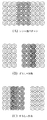
図20(A)〜(C)は、往走査でプリントされるドットと復走査でプリントされるドットが互いに入り組んだプリントパターンを示し、(A)はプリント位置が合っている状態、(B)は少しずれた状態、(C)はさらにずれた状態でプリントされたときのドットを示す模式図である。このようなパターンでも本発明の適用は可能である。
【0133】
図21(A)〜(C)は、ドットが斜めに形成されるパターンを示し、(A)はプリント位置が合っている状態、(B)は少しずれた状態、(C)はさらにずれた状態でプリントされたときのドットを示す模式図である。このようなパターンでも本発明の適用は可能である。
【0134】
図22(A)〜(C)は、プリント位置ずらしの対象となる往復走査それぞれのドット列を複数列とするパターンを示し、(A)はプリント位置が合っている状態、(B)は少しずれた状態、(C)はさらにずれた状態でプリントされたときのドットを示す模式図である。プリント開始タイミング等のプリント位置合わせ条件を広い範囲で変化させてプリント位置合わせを行う場合は、図22(A)〜(C)で示されるようなパターンが有効である。図13(A)〜(C)のプリントパターンでは、ずらしの対象となるドット列の組は往復1列のドット列であるため、プリント位置のずれが大きくなっていくと他の組のドット列と重なり、それ以上にプリント位置ずれ量が大きくなっても反射光学濃度は小さくならないからである。これに対し、図22(A)〜(C)のようなパターンであれば、往復走査それぞれドット列が他の組のドット列と重なるまでのプリント位置ずれの距離を、図13(A)〜(C)のプリントパターンと比べて長くとることができ、これによりプリント位置合わせ条件を広い範囲で変化させることができる。後述する粗調整では実際にこれを利用し、4ドットまでの位置ずれに対応するものである。
【0135】
図23(A)〜(C)は、各ドット列について所定のドットの間引きを行なったプリントパターンを示し、(A)はプリント位置が合っている状態、(B)は少しずれた状態、(C)はさらにずれた状態でプリントされたときのドットを示す模式図である。このようなパターンでも本発明の適用は可能である。このパターンは、プリント媒体上8に形成したドット自身の濃度が大きくて、図13(A)〜(C)に示すパターンをプリントすると全体としての濃度も大きくなりすぎてしまい、光学センサ30がドットずれに応じた濃度差を測定できない場合などに有効である。すなわち、図23(A)〜(C)のようにドットを間引いて少なくすれば、プリント媒体8上のプリントされていない領域が増して、プリントされたパッチ全体の濃度を下げることができる。
【0136】
逆にプリント濃度が低すぎる場合には、同位置について2回のプリントを行なってドットを形成するか、あるいは一部分だけ2回プリントするなどのプリントを行っても良い。
【0137】
プリントパターンについてプリント位置がずれるとともに反射光学濃度が減少する特性には、上述のように往走査でプリントされるドットと復走査でプリントされるドットがキャリッジ走査の方向において接している等の条件が必要となる。しかし、必ずしもパターン全体においてそのような条件を満たしている必要はなく、パターン全体として往走査と復走査のプリント位置がずれるのに従い反射濃度が低下すればよい。
【0138】
(3.2)複数ヘッド間のプリント位置合わせ
異なるヘッド間のキャリッジ走査方向におけるプリント位置合わせの態様について説明する。また、複数種類のプリント媒体、インク、プリントヘッド等を用いる場合にもこれらに対応可能なプリント位置合わせを行う例をも示すものである。すなわち、用いるプリント媒体等の種類により形成されるドットの大きさや濃度が異なることがある。このため、プリント位置合わせ条件の判定に先立って、測定された反射光学濃度の値がプリント位置合わせ条件判定に必要な所定値か否かを判定する。その結果、プリント位置合わせ条件の判定を行うために不適切な値と判定されれば、前述のように、プリントパターン中のドットを間引いたり、ドットの重ね打ちをしたりして反射光学濃度のレベルを調節する。
【0139】
プリント位置合わせ条件の判定に先立って、プリント位置ずれに対し測定された反射光学濃度がそれに応じて十分に減少しているかどうかを判定する。その結果、プリント位置合わせ条件の判定を行うために不適切と判定されれば、プリントパターンにおいて本来的に設定されるキャリッジ走査方向のドット間隔を変更して、再びプリントパターンのプリントと反射光学濃度の測定を行う。
【0140】
ここでは、前述の双方向プリントでの位置合わせで説明したプリントパターンについて、往走査でプリントしていたドットをプリント位置合わせを行う2つのプリントヘッドのうち第1のプリントヘッドでプリントし、復走査でプリントしていたドットを第2のプリントヘッドでプリントするものとしてプリント位置合わせを行う。
【0141】
図24は、本例のプリント位置合わせの処理手順を示すフローチャートであり、この手順も後述する全体アルゴリズムにおける処理の一部として位置づけることができる。
【0142】
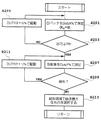
図24に示すように、ステップS121でプリントパターンとして図17に示されるのと同様の9通りのパターン61〜69をプリントするとともに、これらのパターン61等の反射光学濃度の測定を双方向プリントに対する処理の場合と同様に行う。
【0143】
次にステップS122において測定された反射光学濃度の値のうち最も反射光学濃度が大きいものが、OD値で0.7から1.0の範囲に入っているか否かを判定する。その範囲に値が入っていれば次のステップS123の処理に進む。
【0144】
反射光学濃度が0.7〜1.0の範囲にないと判断したときはステップS125へ進み、ここでその値が1.0より大きいときはプリント・パターンのドットを3分の2に間引いた図23(A)〜(C)に示されるパターンに変更してステップS121の処理に戻る。また、反射光学濃度が0.7より小さいときは図13(A)〜(C)に示されるプリント・パターンの上に、図23(A)〜(C)に示されるプリントパターンを重ね打ちする。パターンを変更して同ようにステップS121の処理に戻る。
【0145】
プリントパターンを多く準備しておいて、2回目の判定でも不適当と判定された場合は、さらにプリントパターンを変更してステップS121からS125のループを繰り返しても良いが、ここでは3種類のパターンがあればほとんど全てのケースをカバーできると想定し、2回目の判定で不適当と判断されても次の処理に進む。
【0146】
このステップS122の判定処理により、プリント媒体8やプリントヘッドあるいはインクによってプリントされるパターンの濃度が変化しても、これに対処したプリント位置合わせが可能となる。
【0147】
次にステップS123では、プリント位置のずれに対し測定された反射光学濃度が十分に減少しているか否か、すなわち、反射光学濃度の値のダイナミックレンジが十分あるか否かの判定を行う。例えば、図18に示される反射光学濃度の値が得られた場合において、最大の濃度の値(図18中のプリント位置パラメータ(d)に対応するポイント)と、その2つとなりの値との差(図18では、プリント位置パラメータ(d)に対応するポイントと(b)に対応するポイントとの差、(d)に対応するポイントと(f)に対応するポイントとの差)が0.02以上あるか否かを判断する。ここで0.02未満であれば、プリントパターン全体のプリント・ット間隔が短くすぎる、すなわちダイナミックレンジが十分ではないと判定し、ステップS126でプリントドット間の距離を長くして、再びステップS121以降の処理を行う。
【0148】
このステップS123および次のステップS124の処理を図25(A)〜(C)、図26(A)〜(C)および図27を用いてさらに詳細に説明する。
【0149】
図25(A)〜(C)は、図13(A)〜(C)に示したプリントパターンでプリントドット径が大きい場合のプリント部の様子を模式的に示す。
【0150】
図25(A)〜(C)において、白抜きのドット72は第1のプリントヘッドでプリントしたドット、ハッチの付いたドット74は第2のプリントヘッドでプリントしたドットである。図25(A)はプリント位置が合った条件でプリントした場合、(B)はそれからプリント位置が相対的に少しずれた場合、(C)はプリント位置がさらにずれた場合を示している。図25(A)および(B)の比較からもわかるように、ドット径が大きい場合には、プリント位置が少しずれてもエリアファクタはほぼ100%のままであり、反射光学濃度はほとんど変化することはない。つまり、上述したプリント位置ずれに対し反射光学濃度が敏感に減少するという条件を満たさなくなっている。
【0151】
一方、図26(A)〜(C)は、ドット径はそのままでプリントパターン全体におけるキャリッジ走査方向のドット間距離を長くした場合を示す。この場合は、プリントずれが発生するとともにエリアファクタが減少し全体の反射光学濃度も低下する。
【0152】
図27は、図25(A)〜(C)および図26(A)〜(C)に示すプリントパターンを用いた場合の濃度特性の振る舞いを模式的に示す。
【0153】
図27において、縦軸は反射光学濃度、横軸はプリント位置のずれの量を示す。実線Aは上述した最もプリント位置ずれに対し反射光学濃度が敏感に減少する条件でプリントした場合、破線Bはそれよりもドット間距離が短い場合の反射光学濃度の値の振る舞いを示している。図27から明らかなように、ドット間距離が短すぎると、上述の理由によりプリント位置合わせ条件が理想的な条件から少しずれても反射光学濃度はそれ程変化しない。このため本実施の形態では、図24のステップS123で示した判断を行ない、この判断に応じてドット間距離を長くすることにより、プリント位置合わせ条件の判定を行うために適したプリント条件となるようにする。
【0154】
本実施の形態では初めのドット間距離を短めに設定しておき、適正な反射光学濃度のダイナミックレンジが得られるまで、ドット間距離を長くして行く。しかし、4回ドット間距離を長くしても適正と判断されない場合は、次のプリント位置合わせ条件の判定の処理に進む。本実施の形態では、キャリッジ2の走査速度はそのままに保ちつつ、インクを吐出する間隔を制御するプリント・ヘッドの駆動周波数を変えることにより、ドット間距離を調節する。これにより、プリントヘッドの駆動周波数が小さくなるほど、ドット間の距離が長くなることになる。また、ドット間距離を調整する別の方法として、キャリッジ2の走査速度を変えることも考えられる。
【0155】
上記いずれの場合についても、プリントパターンをプリントする駆動周波数や走査速度が、実際のプリントで使用する駆動周波数や走査速度と異なることになる。したがってプリント位置合わせ条件判定後、その結果により駆動周波数や走査速度の違いを補正する必要がある。その補正は数式によって行っても良いが、予じめ図17に示された9通りのパターン61等毎に実際の駆動周波数や走査速度に関するプリントタイミングのデータも準備しておき、プリント位置合わせ条件判定の結果に従い、それらをそのまま用いることもできる。あるいは図18に示すような場合は、線形補完してプリントに用いるプリント・タイミングを求めることができる。
【0156】
プリント位置合わせ条件判定の方法は双方向プリントの場合と同様である。また、往復プリントにおける往走査と復走査のプリント位置合わせに対しても、ドット径の大きさに対しプリントパターンのドット間の距離を変えることは有効である。ただし、この場合には、使用する数通りのドット間距離のプリントパターンごとに往走査、復走査用のプリントパターンを準備しておく。そして、そのプリントパターンとドット間距離ごとにプリントタイミングのデータを準備しておき、プリント位置判定の結果に従ってそれらを線形補完してプリントに用いるプリントタイミングを求めることができる。
【0157】
なお、図24に示したフローチャート中のパターン変更等の処理は、適宜の修正等を加えて双方向プリントや、次に述べる縦方向のプリント位置合わせに対しても適用できる。
【0158】
(3.3)縦方向のプリント位置合わせ
次に、複数ヘッド間の、キャリッジ走査方向に垂直な方向のプリント位置合わせに関して説明する。
【0159】
本実施の形態のプリント装置では、キャリッジ走査方向に垂直な方向(副走査方向)のプリント位置の補正を行うために、プリントヘッドのインク吐出口を1回のスキャンで形成される画像の副走査方向における幅(バンド幅)よりも広い範囲にわたって設けておき、使用する吐出口の範囲をずらして用いることによって、吐出口間隔の単位でプリント位置を補正できる構成をとっている。すなわち、出力するデータ(画像データ等)とインク吐出口との対応をずらす結果、出力データ自体をずらすことができる。
【0160】
上述した双方向プリントに対するプリント位置合わせおよび複数ヘッドの主走査方向のプリント位置合わせでは、プリント位置が合っている場合に測定された反射光学濃度が最大になるプリントパターンを用いたが、ここではプリント位置が合っている場合に反射光学濃度が最低になり、プリント位置がずれるとともに反射光学濃度が増加していくプリントパターンを用いる。
【0161】
いわゆる紙送り方向(縦方向)の位置合わせの場合においても、上述と同様、プリント位置があった状態で濃度が最大となりプリント位置がずれるとともに濃度が低下するパターンを用いることもできる。例えば2つのヘッド間で紙送り方向において隣り合う位置関係にある各吐出により形成されるドットに注目して位置合わせを行うことができる。
【0162】
図28(A)〜(C)は、縦方向のプリント位置合わせ処理で使用するプリントパターンを模式的に示している。
【0163】
図28(A)〜(C)、白抜きのドット82は第1のプリントヘッドでプリントしたドット、ハッチの付いたドット84は第2のプリントヘッドでプリントしたドットをそれぞれ示している。図28(A)はプリント位置が合っている状態を示しているが、上述の2種類のドットが重なっているため白抜きのドットは見えない。(B)はプリント位置が少しずれた場合にプリントされたドットを、(C)はさらにプリント位置がずれた場合のドットの状態を示している。これらの図からもわかるように、プリント位置がずれるのに従い、エリアファクタが大きくなっていき、全体の平均的な反射光学濃度は増加していく。
【0164】
以上のプリントパターンを、プリント位置調整に係る2つのプリントヘッドのうち一方のプリントヘッドについてプリントに使用する吐出口をずらすことにより、このずらしについてのプリント位置合わせ条件を変えながら複数のパターンをプリントする。そして、そのプリントされたパッチの反射光学濃度を測定する。
【0165】
図29は、測定された反射光学濃度の例を模式的に示し、ここでは例示的に5パターンとしている。
【0166】
図29において、縦軸は反射光学濃度、横軸はプリント吐出口のずれの量を示す。ここでは測定された反射光学濃度の値のうち、最も小さい反射光学濃度を示すプリント条件(図29中の(c))をプリント位置が最も合っている条件として選択する。
【0167】
なお、以上の項目(3.1)〜(3.3)で説明した各位置合わせ処理実施時に用いるパターンは、各処理でのプリント位置合わせのみに限定されるものではなく、必要であれば適宜の変更を加えて他の実プリント位置合わせに対しても同様に用いることができることは勿論である。
【0168】
また、項目(3.2)および(3.3)は、2つのプリントヘッド間の関係についての例を示したが、3つ以上のプリント・ヘッド間の関係についても同様に適用できる。例えば、3つのヘッドに対しては、第1のヘッドと第2のヘッドのプリント位置を合わせ、その後第1のヘッドと第3のヘッドとの位置を合わせればよいのである。
【0169】
4.ドットアライメント処理のアルゴリズムの第1例
以上を基本として、自動で行われるドットアライメント処理のアルゴリズムの一例について説明する。
【0170】
図30は本例における自動ドットアライメント処理手順の概要を示し、概ね回復処理ステップ(ステップS101)、センサキャリブレーション処理ステップ(ステップS103)、双方向記録の粗・微調整ステップ(ステップS105,S107)および調整値確認パターンプリント処理ステップ(ステップS111)から成っており、主として同一のプリントヘッドを用いて往走査および復走査のそれぞれのプリントでの着弾位置を最適な条件で位置合わせするために実行される。
【0171】
なお、本手順を起動するための手段としては、プリント装置本体に設けた起動スイッチや、ホストコンピュータ側のアプリケーションからの指示とするほか、装置電源投入時やタイマ起動など、適宜のものとすることができる。また、それらの組み合わせであってもよい。
【0172】
また、例えばセンサキャリブレーション処理において使用可能範囲外のデータを獲得するようなキャリブレーションエラーが生じた場合や、あるいはドットアライメント処理の過程で外乱光等の影響により極端に反射光が強くなりその結果として粗調整エラーまたは微調整エラーが生じたような場合は、通常のマニュアル調整を実施する(ステップS119)。この処理については後述する。
【0173】
かかるマニュアル調整に移行する条件や、センサエラーが偶然の外乱光の入射のように一過性であるような場合に、時間を置いたりあるいは条件を整えるようユーザに報知する等した上で再度ドットアライメント処理を起動するようにすることができることについては、項目(1.5)において説明したとおりである。
【0174】
以下、各ステップでの処理内容について詳述する。
【0175】
(4.1)回復処理
前述のように、回復処理は、自動ドットアライメントを実行する前に、吸引・ワイピング・予備吐出など、プリントヘッドのインク吐出状態を良好にする、または良好に保持するための一連の動作であり、自動ドットアライメントの実行命令があった場合に、それを実行する前に行なわれる。これにより、プリントヘッドの吐出状態が安定した状態でプリント位置合わせのためのパターンをプリントすることができ、より信頼性の高いプリント位置合わせの補正条件の設定が可能となる。
【0176】
回復動作としては吸引・ワイピング・予備吐出という一連の動作にのみ限定されず、予備吐出または予備吐出とワイピングだけでも良い。この場合の予備吐出はプリントの際の予備吐出よりも発数の多い予備吐出を行うように設定するのが好ましい。また、吸引、ワイピング、予備吐出の回数や動作順序といった組み合わせについても特に限定させるものではない。
【0177】
また、前回の吸引回復からの経過時間に応じて自動ドットアライメント制御前の吸引回復の実行の要否を判断しても良い。この場合、まず自動ドットアライメントを行う直前に前回の吸引動作から所定時間が経過したどうかを判定する。そして、所定時間以内に吸引動作が実施されていたなら、自動ドットアライメントレジを実施する。一方、所定時間以内に吸引回復動が実施されていなければ、吸引回復を含んだ一連の回復動作を実施した後に自動ドットアライメントを行うようにすることができる。
【0178】
また、前回の吸引回復からプリントヘッドが所定の吐出数以上のインク吐出を行ったか否かを判定するようにし、所定の吐出数以上のインク吐出を行っている場合には回復動作を実行してから自動ドットアライメントを実施するようにしても良いし、さらには経過時間とインク吐出数との双方を判断材料として、いずれかが所定値に達していたら吸引回復を実施するように組み合わせても良い。
【0179】
このようにすることで、吸引回復を過剰に実施することを防止することができるので、インクの消費量の節約および廃インク処理部へのインク排出量の低減に資することができるとともに、自動ドットアライメント前の回復動作を効率的に行うことができる。
【0180】
また、前回の吸引回復からの経過時間、もしくはインク吐出数に応じて回復条件を可変にし、例えば経過時間が短い場合には吸引動作をさせずに予備吐出とワイピングとのみを行い、経過時間が長い場合にはさらに吸引回復を介挿するというように回復条件を変更するようにしても良い。
【0181】
以上述べてきたように必要に応じて回復動作を実施しているが、必ずしも回復動作を実施する構成を用いる必要はなく、もともと信頼性の高いプリント装置であれば、自動ドットアライメント処理内で回復動作を実施する必要はない。高い信頼性を確保した上で自動ドットアライメント処理を実施した方がより好ましいのである。
【0182】
(4.2)センサキャリブレーション
次に、光学センサ30が有するLEDのキャリブレーションの一例では、光学センサの出力特性として所定のレンジが得られるように、望ましくは線形領域で使用することができるようにキャリブレーションを行うべく、投入電力をPWM制御している。具体的には投入する電流をPWM制御して、例えば100%デューティのフル通電から5%デューティの通電まで、5%間隔で通電する電流量を制御し、これにより最適な電流デューティを得て光学センサ30のLEDを駆動するようにするのも一つの例である。
【0183】
これは次のような理由による。
【0184】
すなわち、プリント位置合わせの条件を変化させたパターンに光センサ30の発光側から光を照射し、その反射光出力の相対値から最適なプリント位置合わせ条件を判定するためには、最適な光量を照射し、受光側には最適な電気信号を印加しなければ良好な出力差は得られない。十分な出力差(実際のプリント位置合わせパターンでプリント位置を最小限に変化させた時のパターン間出力差)を得るためには、センサ(発光部側および/または受光部側)自体のキャリブレーションを行うのが強く望ましい。
【0185】
そしてこれは、濃度センサ(光学センサ)固有のバラツキ、プリント装置におけるセンサ取り付け公差、使用環境の光や湿度、空気の状態(霧、煙)等の雰囲気差、センサ自体の経時変化、畜熱による出力低下の影響、センサに付着するミスト,紙粉等による出力低下の影響などを補正する上で好ましいことである。この観点から言えば、本発明のセンサキャリブレーション方法は、自動ドットアライメントを実施する上で用いられる光学センサのみならず、プリント媒体の有無、紙幅の検出を行うための光学センサやヘッドシェーディングに用いられるセンサなど、広く測定対象物から何らかの情報を得る際に用いられる光学センサに適用できるものである。
【0186】
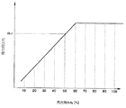
ここで、発光部側のキャリブレーションについて説明する。
【0187】
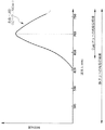
図31は所定領域に対するインク打込み率を変化させた場合の反射率の関係を表したものであり、この図に示すように、ある打込み率以上では反射率が飽和してくる特性(位置A以上)がある。センサ自体の出力特性は発光側の照射光に対する反射光の変化を測定するものであり、所定領域のエリアファクタに強く依存している。この例では位置Aにおける打込み率以上打込んでもエリアファクタは実質的に変化しないため、反射率にも変化が見られなくなっている。実際のプリント位置合わせにおいても、このエリアファクタの変化に大きく依存している範囲、すなわち打込み率ではなく反射率の不飽和・線形範囲に主眼を置く。
【0188】
図32は、発光側に印加する電気信号の最大定格値を100%とし、これを発光量が変化する最小単位で順次0%から100%まで変化させ測定された出力特性を、反射率を変化させたパターンに対応させて示したものである。光量が弱すぎれば、反射率の異なるパターンの出力間には反射光量が少なすぎて出力差は乏しくなる。逆に発光量が強すぎれば、反射率が異なるパターンの出力は、白地に近いような反射率のパターンにおいては反射光が大きく、受光側の検出能力を超えた時点で白地の出力とほとんど差が見られなくなるので、実際のプリント位置合わせのパターンでこのような反射率領域のパターンが存在すれば出力差が良好に得られない。ここではプリント位置合わせに用いられるパターンの反射率領域で出力差が得られることが重要である。図32で実際にプリント位置合わせのパターンの反射率領域をA〜Bの範囲に限定した場合、▲1▼〜▲4▼までの出力特性が線形であるが、実際のプリント位置合わせを行う場合には▲4▼の特性が良好なS/N比を確保できていると言える。
【0189】
発光側の駆動信号の変調はプリンタ内部のMPU101の処理で行い、その変調単位量は発光量が変化する最小単位で行うことができる。
【0190】
受光側のキャリブレーションに関しても同様であり、上記のような方法でプリント位置合わせパターンの反射率を測定する上で最適な電気信号印加条件を決定することができる。そして受光側の駆動信号の変調はプリンタ内部のMPU101の処理で行い、その変調単位量は発光量が変化する最小単位で行うことができる。
【0191】
また、プリンタ内部に出力値を格納するバッファをもち、その出力値を予めプリンター部に設定された閾値と比較処理可能な手段を持つことができる。
【0192】
ここで、上述のようなキャリブレーションを行うためには基準となる測定対象物を要する。本実施形態ではセンサキャリブレーションはドットアライメント処理の前提として行われるものであり、ドットアライメントに際してはプリント媒体に所定のパッチをプリントする動作を伴うようにしているので、当該プリント媒体に測定対象となるセンサキャリブレーション用パターンをプリントするようにする。センサキャリブレーションは各ドットアライメント処理(ドットアライメント処理の第1例では双方向プリントに対する粗調整および微調整、さらには後述する第2例においては複数ヘッド間の粗調整および微調整、さらに縦方向調整)毎に行われるようにしてもよく、プリント媒体の先頭部分(頁頭)にのみセンサキャリブレーション用パターンをプリントを形成して一連のドットアライメント処理に先立ち1回のセンサキャリブレーションが行われるようにしてもよい。
【0193】
また、そのようにドットアライメント処理用のパッチを形成するプリント媒体を利用するものとするほか、プリント装置本体に搭載されたものとしたり(例えばプラテンにこのような構成を付加する)、測定対象物のみが別体となったプリント媒体や金属板などを利用することも可能である。
【0194】
次に、センサキャリブレーションに用いられる測定対象物(キャリブレーションパターン)はセンサ発光波長に敏感に反応する色で構成されている。単色でもよいし、所定領域内の位置によって反射率が変わらなければ複数色を組み合わせたものでもよい。
【0195】
なお、反射率を変化させたセンサキャリブレーション用パターンを用いる場合は、それぞれが独立のパッチになっているパターンとしてもよいし、反射率を変化させた部分パターンが連続したものでもよい。
【0196】
また、センサキャリブレーションにあたっては、電気信号を大雑把に変化させて粗調整を行った後に、微少に変化させて微調整を行ってもよいし、最初から微少に変化させて行ってもよい。
【0197】
また、センサキャリブレーションにあたっては、印加する電気信号をキャリッジ主走査の過程で変化させつつ測定を行っても良いし、キャリッジを停止した上で変化させて測定を行ってもよい。さらに、キャリブレーションは1スキャン内で行ってもよいし、複数スキャンで行ってもよい。
【0198】
次にセンサキャリブレーションのいくつかの具体例について説明する。
【0199】
(4.2.1)センサキャリブレーション処理の第1例
反射率を変化させたパターンを、発光側および/または受光側に印加する電気信号を変化させて測定し、予めプリンタ内部のROM等に設定された感度特性(出力特性の傾き)に最も近い、もしくはそれ以上のものを用いて以後のプリント位置合わせ測定を行うようにする。上記の反射率を変化させたパターンは実際のレジ調パターンで用いられる反射率領域でも良いし、反射率全域(0から100%)でもよい。
【0200】
図32は反射率が異なる測定対象(例えば0〜100%間を10%刻みの反射率で形成したパターン)の反射濃度(出力)を、発光側の電気信号を変化させて測定した結果を示す。図の横軸には反射率、縦軸には反射濃度(出力)をとった。
【0201】
図33は理想的な感度(出力)特性を示しており、反射率を変化させたときに反射光濃度(出力)が線形に変化する状態である。発光側に印加する電気信号のデューティが小さすぎ所定パターンからの反射光の変化量が受光側の分解能より低い場合、図32の特性▲1▼のように出力変化が乏しい。デューティが大きすぎれば同じく特性▲5▼のように反射光量が受光側の最大検出幅を超えた時点で反射濃度(出力)自体には変化が見られなくなる。ここでは全反射率領域(0から100%)で出力変化があることを前提にしているが、実際に使用されるプリント位置合わせの反射率領域にあわせて十分に出力変化が得られる領域を用いてもよい。ここで十分に出力変化が得られる条件としては実際のプリント位置合わせパターンで最小限にプリント位置をずらした場合に出力変化が得られることを意味する。
【0202】
そして、実際にプリント位置合わせに用いる図33に示すような理想的な出力特性を装置本体に設けておき、この特性に近似できる(図中破線で示す10%下げた特性を用いるなど、ある程度の幅を持たせてもよい)、発光側および/または受光側の駆動デューティを選定する。
【0203】
(4.2.2)センサキャリブレーション処理の第2例
反射率を変化させたパターンを、発光側および/または受光側に印加する電気信号を一定量として測定し、複数個(最小2個)の出力データから感度特性(出力特性の傾き)を算出し、感度特性算出に用いた測定値以外の測定値がその特性曲線から推定された値から外れている場合は、印加する電気信号を変化させて同様な判断を繰り返し行う。この判断から複数の印加量が当てはまった場合はその中で最も出力特性の傾きが大きなものを選択してもよいし、ある幅を予めプリンタ内部に設定しておき、適宜選択してもよい。上記同様この出力特性は実際のレジ調パターンで用いられる反射率の範囲でも良いし、反射率全域(0から100%)でもよい。
【0204】
すなわち、図34に示すように、発光側および/または受光側に印加する電気信号のデューティを一定量として複数個(最小2個)の測定パターンの反射濃度(出力)を得、これから仮想感度特性(出力特性の傾き)を算出し、仮想特性算出に用いたもの以外の測定値がその特性曲線から外れている場合(例えば特性▲3▼)は、それ以外のデューティで繰り返し同様な操作を行い、理想的な特性(線形な傾き)に最も近い特性(▲2▼または▲1▼)を示すときのデューティを選定する(ある程度の幅を持たせてもよい)。
【0205】
(4.2.3)センサキャリブレーション処理の第3例
所定パターン(ドット打ち込み率0%の白パッチ、またはそれ以外の打ち込み率でベタに形成したパッチ等)を、発光側および/または受光側に印加する電気信号を変化させて測定し、その出力値(反射濃度)が予めプリンタ内部に設定された閾値に達しているものを用いて以後のプリント位置合わせ測定を行うようにする。
【0206】
すなわち、反射率を固定した測定対象(例えば50%ベタパッチのみ)について反射光濃度(出力)を測定すれば、その出力特性はおおよそ推定できる。この特徴を利用したのが本例である。
【0207】
図35は例えばプリント媒体に打込み率50%のパターンをプリントし、これを用いて発光側キャリブレーションを行った場合の出力特性を示す。発光側に印加する電気信号のパルス幅(デューティ)を可変させていくと、あるデューティからは出力に変化が見られなくなる。この状態は受光側の検出幅以上の反射光が検出された場合である。そこで、予めプリント装置本体に用意した閾値Rthと比較し、その閾値に最も近い(ある程度の幅を持ってもよい)デューティを選択する。
【0208】
(4.2.4)センサキャリブレーション処理の第4例
上記処理を組み合わせて行う。すなわち例えば第3例の処理で電気信号を変化させて測定を行い、閾値を超えた時点で第1例または第2例の処理に切り替えるようにする。
【0209】
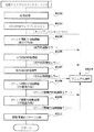
図36は本例の処理手順の一例であり、上記第3例の如くセンサキャリブレーション用の所定のパターン(例えば打込み率0%の白パッチ)を発光側に印加するデューティを変化させて測定し(ステップS201,S205)、予め設けられた閾値と比較し(ステップS203)、その閾値を超えたデューティから上記第1例の如く線形となる出力特性を選定する(ステップS207,S209,S211)。そして、例えば閾値を用いる調整手順では5%刻みでデューティを変化させて行い、その後傾きが最大となる線形領域を1%刻みでデューティを変化させて得るようにしている。これによりセンサキャリブレーションについての粗調整、微調整を行い、より的確かつ迅速に最適のセンサ駆動デューティを決定し、以後のプリント位置合わせに移行することが可能となる。
【0210】
なお、図36の処理手順は、第4例を用いる場合はほぼそのまま、第1ないし第3例を用いる場合は適宜の変更等を加えて図30のステップS103として位置づけることができる。
【0211】
また、以上のようないずれかのセンサキャリブレーションを行い、最適または適切なデューティも決定できなかった場合を考慮し、プリント装置本体にエラー処理手段を設ける。この場合は、前述のように、再び同じ処理(自動レジストレーション調整)を繰り返すもの、または他の手段(マニュアルレジストレーション調整)を促すメッセージをプリント装置本体もしくはホスト装置等からユーザーに告知するものとすることができる。
【0212】
(4.3)双方向プリントに対するプリント位置合わせの粗調整
次に、双方向プリントにおけるプリント位置合わせの粗調整(図30のステップS105)について説明する。本実施形態ではプリント装置本体およびプリントヘッドで双方向プリントを実施する上での相対的なプリントドットの着弾位置の公差精度は、±4ドット以下にあるものとする。従って、粗調整では4ドットの幅を持つパターンを用いる。
【0213】
図37は粗調整に用いるパッチのパターンの一例を示す。基準ドットを往走査プリントで形成し、位置合わせ条件を変えてプリントを行うずらしドットを復走査プリントで形成する。無調整でプリントを行った場合をずらし量:0ドットとする。この状態でプリントした場合(図中(c))のずれがプリント装置本体およびプリントヘッドでの着弾位置精度に起因するものであり、それぞれの製造上のバラツキ等により発生するものである。本例は、このずれを自動的に調整するものである。
【0214】
図37ではずらし量:±4ドットの範囲内の各パターンのプリントを行っているが((a)〜(c))、これらのパターンにおいてずらし量は最大で4ドットで十分である。
【0215】
図38中の実線はこの場合のずらし量に対する光学センサの出力(反射してきた光を受光し、A/D変換後の値)の特性を示す。また、ずらし量に対する出力特性を多項式で近似した特性を破線で示す。この近似特性から反射濃度が最大のポイントをずらしの調整値、つまり双方向プリントを行う場合の調整値とすることができる。
【0216】
なお、この場合の調整値はずらし量の間隔より細かく設定することができる。また、この時点では近似を行わずに、反射濃度の最大値を示すずらし量を双方向プリントの調整値としても良い。パターンのずらし量の間隔は2ドット間隔でも良いが、当然1ドット間隔でも良い。さらに、不均等間隔にしても良いし、1ドット間隔以下の精度でずらしても良く、着弾位置の公差精度の範囲内で近似特性が得られる間隔であれば実施できる。
【0217】
(4.4)双方向プリントに対するプリント位置合わせの微調整
次に、双方向プリントにおけるプリント位置合わせの微調整(図30のステップS17)について説明する。より細かい調整精度で微調整を実施するに際しては、上述した粗調整において1ドット間隔以内に調整が行われたことを前提として、±0.5ドット以内で微調整を行う。微調整はより高い精度で調整を行うので、最小の幅のパターンを用いる。
【0218】
図39は微調整で用いるパターンの一例を示す。粗調整と同様に、基準ドットを往走査プリントでプリントし、位置合わせ条件を変えてプリントを行うずらしドットを復走査プリントでプリントする。無調整でプリントを行った場合(図中(c))をずらし量:0ドットとする。本例では0.25ドット間隔で位置合わせ条件を設定している(図中(a)〜(c))。ここで、粗調整と同様に、ずらし量に対する光学センサの出力特性を多項式で近似した特性を求め、この近似特性から反射濃度が最大となるポイントをずらしの調整値、つまり双方向プリントを行う場合の調整値とすることができる。
【0219】
なお、本例の場合の調整値はずらし量の間隔、つまり0.25ドットより細かく設定することもできる。また、要求されている調整精度がずらし量の間隔と同等であるならば、近似を行わずに反射濃度の最大値を示すずらし量を双方向プリントの調整値としても良い。
【0220】
しかし本例では、さらに調整精度を高めるために次のような方式を用いる。
【0221】
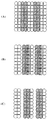
図40〜図43を用いて本方式を説明する。
【0222】
まず、往走査および復走査プリントにてプリントドットが主走査方向に関し相補的に1ドットおきに形成される図40の(a)に示すような場合にあってドットアライメントを行うに際し、復走査プリントでのドット形成位置をずらしてパッチを形成しても、同図の(b)に示すように濃度変化が乏しく好ましい濃度出力を得られない場合があるので、本例では同図の(c)に示すように往復主走査について2ドットおきのプリントを行うものとする。
【0223】
さて、隣接する基準ドットとずらしドットとの2ドットについて考えた場合、それらが接する状態が最もドットで覆われる領域の面積が大きく、それ以上ドットが離れていってもドットで覆われる面積の合計は変化しない。つまり、濃度変化はない。逆に、接する状態から近づいていくと、ドットで覆われている領域の面積は、着弾位置の変化に従って減少していく。つまり、濃度が着弾位置に従って変化する。
【0224】
画素密度とドット直径の関係から、エリアファクタを100%にするために1画素の√2倍の大きさのドット直径とした場合、着弾位置が合っている状態では隣接するドットには重なる部分が必ず存在する。従って、着弾位置が合っている状態はドットの着弾位置で濃度が大きく変化する領域であると言える。
【0225】
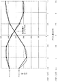
図41に示すように、往走査で形成する基準となるドットに対して、復走査ドットの着弾位置の位置合わせ条件(ドットずらし量)を変えて形成したパッチ群(パターン▲1▼)の濃度変化(破線は多項式近似したもの)と、当該各位置合わせ条件毎に、基準となるドットに対して線対)となる位置に復走査ドットを形成することによって得たパッチ群(パターン▲2▼)の濃度変化(破線は多項式近似したもの)とは同様の特性となり、調整方向の方向性により、濃度変化の特性が反転しているだけである。この特性を利用して、2つの濃度変化の特性の交点が丁度、ドットの着弾位置が合っている調整位置として求めることができる。
【0226】
この調整方法は微妙な着弾位置のズレが濃度変化に敏感に現れるために、厳密な着弾位置の調整に向いており、精度の良いドットアライメントを実現することができる。
【0227】
また本方法は、調整方向の方向性に応じた特性曲線を測定値から求めた近似曲線としても良いし、交点付近の複数点から近似直線を求めても良い。
【0228】
以上述べてきたように、曲線近似または直線近似を用いて特性曲線の交点から調整位置を求めているが、調整間隔が必要な精度の間隔であれば、特性曲線の近似式を求める必要はない。例えば、2つの特性の出力AD値(濃度)の差が最も小さい点を調整位置として求めてもよく、近似式を用いる構成に特に限定されるものではない。
【0229】
パターン▲1▼を得る際には、図42に示すように、ずらし量を0ドットとするパッチ(図中の(c))に対して、正負各方向(図の左方向を正とする)に0.5ドット刻みで復走査プリントでの着弾位置をずらしたパッチ(図では(a),(b),(c))を形成すればよい。一方、基準ドットに対して復走査ドットがパターン▲1▼とは線対称となる位置に形成されるパターン▲2▼(反転パターン)を得る際には、図43に示すように、まずパターン▲1▼でのずらし量0の場合に対して2ドット分だけ図の左方向に復走査ドットをシフトして形成するパッチ(図中の(c))に対して、正方向には0.5ドット刻みで復走査プリントでのずらし量を減じたパッチ(図では(a),(b))を、負方向には0.5ドット刻みで復走査プリントでのずらし量を増したパッチ(図では(c))を形成すればよい。
【0230】
なお、この例では微調整について2パターンの特性の交点を求めてドットアライメント処理を行うものとしたが、粗調整について行うこともできるのは勿論である。
【0231】
(4.5)確認パターンのプリント
最後に、ドットアライメントが成功したことをユーザが確認するために、確認パターンをプリントする。確認パターンは、ユーザが認識しやすい罫線パターンなどを用い、粗調整および微調整で求めた調整値を用いて双方向プリントを行う。つまり、調整を行うための濃度を測定する調整パターンと調整の確認をするための確認パターンの2つの種類(センサキャリブレーション時のものを加えれば3種類)のプリントパターンがプリント媒体上に形成されるのである。
【0232】
なお、プリント媒体上に形成されるパターンの具体例についてはモードに応じたドットアライメント処理において説明する。
【0233】
(4.6)本例の効果等
ドットアライメント処理のアルゴリズムの第1例においては、双方向プリントのプリント位置合わせについて粗調整と微調整との2段階の調整方法を有することにより、プリント装置本体およびプリントヘッドの双方向プリントでの相対的なプリントドットの着弾位置の公差精度の最大値から、高精度の調整までを一連の自動ドットアライメントシーケンスで実施することができる。
【0234】
また、予め粗調整を行っておくことで微調整の範囲を小さくし、すなわち調整を迅速に行うことができる。これはシーケンス全体のスループットの向上に有効である。また、ユーザにマニュアル調整のみを行わせる場合には、途中にユーザに判断を強いることになり、誤判断による調整ミスの発生も起こりうるが、本例ではこれを抑制することができる。
【0235】
以上説明してきたように、本例では同一のプリントヘッドを用いて往走査と復走査によりそれぞれプリントを行い画像を形成するプリント方法において、本ドットアライメント処理を用いて最適な調整値を求めることにより、プリントドットの往走査の着弾位置と復走査の着弾位置を最適な位置条件に設定してプリントを行うことが可能になる。これにより、着弾位置のずれない双方向プリントを行うことができるプリント方法を実現できる。
【0236】
なお、本例では粗調整を行った上で微調整を行うようにしたが、この順序は逆でもよい。その理由については後述する。
【0237】
また、実施形態ではプリントしたドットの着弾位置精度に起因して変化する面積の変動を反射濃度として検出するものである。従って、センサキャリブレーションやプリント位置合わせのために形成されるパターンは、入射光に対してプリントドットが十分な吸収特性がある色でプリントを行うのが強く望ましい。赤色LEDを用いる場合、吸収特性の点からはBkまたはCyanが好ましく、十分な濃度特性、S/N比を得ることができる。そこで、本例では、最も吸収特性に優れたBkドットを用た。
【0238】
これは、図44に示すようにBkが赤色光のスペクトル特性上、全領域に対して光吸収が可能であるからである。Cyanに関しては、赤色の補色に相当し、高い吸収特性を有するが、赤色光そのものが理想的な光ではなく、スペクトル特性上広がりを持っているため、Cyanドットでは吸収しきれないスペクトル成分が存在する。従って、全領域について吸収可能なBkよりは吸収特性が若干落ちる。
【0239】
もっとも、用いるLEDの特性に応じて、ドットアライメントに使用する色を決めることにより、各色に対応させることもできる。逆に、パターンを形成する色に応じてLEDを選定することもできる。例えば、赤色以外に青色LED、緑色LED等を搭載することで、Bkに対して、各色(C、M、Y)毎にドットアライメントを行うことができる。また、各色吐出部(ヘッド)が別体に構成されてプリント装置に並置されて用いられるような場合にはすべての色についてプリント位置合わせを行うことが好ましいので、それに応じたセンサを用意し、それぞれについて所要のキャリブレーションを行えばよい。
【0240】
5.ドットアライメント処理のアルゴリズムの第2例
本例では複数ヘッド間のドットアライメント処理をも行う場合について説明する。すなわち、本例では双方向プリントのドットアライメントに加え、2ヘッド間の縦方向および横方向のドットアライメントを実施している。
【0241】
図45は本例における自動ドットアライメント処理手順の概要を示し、概ね回復処理ステップ(ステップS101)、センサキャリブレーション処理ステップ(ステップS103)、2ヘッド間縦方向調整ステップ(ステップS104)、双方向記録の粗・微調整ステップ(ステップS105,S107)、2ヘッド間主走査方向の粗・微調整ステップ(ステップS108,S109)、および調整値確認パターンプリント処理ステップ(ステップS111)から成っている。
【0242】
なお、本手順を起動するための手段としても、プリント装置本体に設けた起動スイッチや、ホストコンピュータ側のアプリケーションからの指示とするほか、装置電源投入時やタイマ起動など、適宜のものとすることができる。また、それらの組み合わせであってもよい。
【0243】
回復処理(ステップS101)については上例と同様である。また、例えばセンサキャリブレーション処理において使用可能範囲外のデータを獲得するようなキャリブレーションエラーが生じた場合や、あるいはドットアライメント処理の過程で外乱光等の影響により極端に反射光が強くなりその結果として粗調整エラーまたは微調整エラーが生じたような場合は、通常のマニュアル調整を実施すること(ステップS119)等についても上例と同様である。
【0244】
センサキャリブレーション処理(ステップS103)についても上例とほぼ同様であるが、本例では異色の複数ヘッド間のプリント位置合わせを伴うため、これを考慮して当該処理で用いるパターンの形成色を上例と異ならせることもできる。
【0245】
センサキャリブレーションが実施されたあとの最初の調整として、本例では2ヘッド間の縦方向の粗調整を行う(ステップS104)。
【0246】
本実施の形態のプリント装置では、キャリッジ走査方向に垂直な方向(副走査方向)のプリント位置の補正を行うために、各プリントヘッド(吐出部)のインク吐出口を1回のスキャンで形成され得る画像の副走査方向における最大幅(バンド幅)よりも広い範囲にわたって設けておき、使用する吐出口の範囲をずらして用いることによって、吐出口間隔の単位でプリント位置を補正できる構成をとっている。すなわち、出力するデータ(画像データ等)とインク吐出口との対応をずらす結果、出力データ自体をずらすことができる。
【0247】
すなわち縦方向の調整は画像データの位置で調整を行い、縦方向のプリント位置合わせ精度はプリントヘッドの解像度およびプリント媒体の送り方向の制御解像度に依存するので、ここでは、粗調整のみを行っている。しかし必要に応じて他と同じように微調整も行うことができる。
【0248】
実施形態で用いた装置は、図6に示したようにBkのインクを吐出するノズルを配列したBkインク吐出部と、それぞれY、MおよびCのインクを吐出するノズル群を一体かつインラインにBkの吐出口配列範囲に対応して配列してなるカラーインク吐出部とが並置されたヘッドを用いるものである。従って、特に複数ヘッド(吐出部)間の縦方向ドットアライメント処理にあたって、Bkと例えばCとの間のプリント位置合わせを行えば、Cインクの吐出口群と同時工程で製造されて一体かつインラインとなっているMおよびYインクのノズル群のBk吐出部に対するプリント位置合わせも実質的に行われ、すなわち複数ヘッド(吐出部)間のドットアライメント処理が完了する。従って特に複数ヘッド(吐出部)間のドットアライメント処理にあたって赤色のLEDを発光部として採用する一方、赤色光に対して十分な吸収特性のあるBkおよびCインクを使用して測定パッチを形成してプリント位置合わせを行えば足りるのである。
【0249】
もっとも、用いるLEDの特性に応じて、ドットアライメントに使用する色を決めることにより、各色に対応させることもできる。逆に、パターンを形成する色に応じてLEDを選定することもできる。例えば、赤色以外に青色LED、緑色LED等を搭載することで、Bkに対して、各色(C、M、Y)毎にドットアライメントを行うことができる。また、各色吐出部(ヘッド)が別体に構成されてプリント装置に並置されて用いられるような場合にはすべての色についてプリント位置合わせを行うことが好ましいので、それに応じたセンサを用意し、それぞれについて所要のキャリブレーションを行えばよい。以下に述べる横方向調整においても同様である。
【0250】
次に、上例と同様双方向プリントの粗調整を行い(ステップS105)、さらに双方向プリントの微調整を行って、最高精度での調整を実施する(ステップS107)。双方向プリントの場合、往走査プリントおよび復走査プリントの相対的な着弾位置精度の調整は、各走査での駆動タイミングを調整することで行う。
【0251】
ここで、当該調整はBkについてのみ行ってもよいし、他色について行ってもよく、双方向プリントに係る色に応じた処理を行えばよい。
【0252】
次に、2ヘッド間の横方向(主走査方向)の粗調整を行い(ステップS108)、さらに横方向の微調整を行う(ステップS109)。横方向の調整は各ヘッド間での駆動タイミングを調整することで行う。そして、これら粗・微調整についても、2ヘッドについて上例の図37〜図43を用いて説明したと同様の処理が行われる。
【0253】
実施形態で用いた装置は、図6に示したようにBkのインクを吐出するノズルを配列したBkインク吐出部と、それぞれY、MおよびCのインクを吐出するノズル群を一体かつインラインにBkの吐出口配列範囲に対応して配列してなるカラーインク吐出部とが並置されたヘッドを用いるものである。従って、特に複数ヘッド(吐出部)間の横方向ドットアライメント処理にあたって、Bkと例えばCとの間のプリント位置合わせを行えば、Cインクの吐出口群と同時工程で製造されてインラインとなっているMおよびYインクのノズル群のBk吐出部に対するプリント位置合わせも実質的に行われ、すなわち複数ヘッド(吐出部)間の横方向ドットアライメント処理が完了する。従って特に複数ヘッド(吐出部)間のドットアライメント処理にあたって赤色のLEDを発光部として採用する一方、BkおよびCインクを使用して測定パッチを形成して横方向プリント位置合わせを行えば足りるのである。
【0254】
最後に、上例と同様調整値の確認パターンをプリントして本自動ドットアライメントシーケンスを終了する(ステップS111)。
【0255】
なお、本例において、横方向のドットアライメントは、各ヘッド間での往走査プリントでの調整だけではなく、復走査プリントでの調整も行う。これは1つのヘッドで双方向プリントのドットアライメントを調整した場合、その他のプリントヘッドにおいてその調整値を用いても着弾位置ずれを生じることがある。各プリントヘッドにおいてインクの吐出方向が異なっていたり、吐出速度が異なっていたりすると、プリントヘッド毎に双方向プリントの状態が異なってしまうためである。このような現象に対して、双方向プリントの調整値が1つのみ設定できる場合、双方向プリントを基準となる1つのプリントヘッドでドットアライメントを実施する。次に、双方向プリントの基準になったプリントヘッドを横方向においても基準として、横方向のドットアライメントを各走査プリント毎に行う。これにより、プリントヘッドの特性に起因する双方向もしくは横方向の着弾位置のずれの発生を抑制することができる。
【0256】
また、双方向プリントの調整値が複数設定できる場合には、各プリントヘッド毎に双方向プリントのドットアライメントを行い、横方向は1つの方向にのみドットアライメントを行うことで、各プリントヘッドの特性が異なる場合でも着弾位置の調整をすることができる。
【0257】
また、ドットアライメント処理時ないしはその結果を用いる実際のプリント動作時において着弾位置をずらすには、以下を適用することができる。
【0258】
双方向プリントに対しては、例えばキャリッジモータ6のトリガ信号の発生間隔に等しいインターバルを用いた吐出開始位置制御により行う。この場合、ゲートアレイ140に対し例えばソフトウェアにて80nsec間隔を設定することができる。しかし必要な解像度を持っていれば良く、2880dpi(8.8μm)程度で充分な精度となる。
【0259】
複数ヘッドを用いるプリントの横方向については、画像データを720dpi間隔で制御することにより行う。そして、1画素以内のずれについては、例えば、ノズル群がいくつかのブロックに分けられて時分割に駆動される形態にあっては、複数ヘッド間の720dpi駆動用のブロック選択順序を変えることで、また、1画素以上のずれについてはプリントする画像データを複数ヘッド間でずらすことで制御する。
【0260】
複数ヘッドを用いるプリントの縦方向については、画像データを360dpi間隔で制御し、プリントする画像データを複数ヘッド間でずらすことで制御する。
【0261】
6.モード等に応じたドットアライメント処理
次に、プリント装置が持つモード(例えばプリントドットの大きさを変更して高解像度プリント等を行うモード)等に応じて自動ドットアライメントの制御の変更(例えばプリントドットの大きさに応じた変更)を行う場合について説明する。
【0262】
インクジェットプリント装置の場合、プリントドットの大きさは主にプリントヘッドから吐出されるインク量で決定される。
【0263】
図46は吐出インク量を変化させることのできる吐出ヒータ部の構成例を示す拡大図である。ここで、5000は図7について述べたヒータボードHBのエッジであり、吐出用ヒータに対してこの側面がインク吐出口側となる。図示の例においては吐出用ヒータ部5013は2つの吐出用ヒータ5002および5004を有している。ここでは、吐出口方向前側にある吐出用ヒータ5002のサイズは、長さLf=131μm、幅Wf=22μmであり、後側にある吐出用ヒータ5003のサイズは、長さLb=131μm、幅Wb=20μmである。5001は各ヒータへの共通配線を示し、グランドラインに接続される。5003および5005は、それぞれ、ヒータ5002および5004を選択的に駆動するための個別配線であり、ヒータへの通電をオン/オフするヒータドライバに接続される。
【0264】
2つの吐出用ヒータ5002,5004を1つの吐出口に対して設けることで、細密なプリントが要求される場合にはいずれかの吐出用ヒータを駆動して対応した部位にのみバブルを発生させることにより、吐出量を比較的小としたインクドットでプリントを行って高解像度を実現することができる。一方いわゆる「ベタ」プリントを行うような場合には、双方のヒータを駆動してそれらの上方を覆う比較的大きなバブルを発生させることにより、吐出量を比較的大としたインクドットでプリントを行ってプリント効率を向上することができる。
【0265】
このように吐出されるインク量が異なる場合には、主走査速度、吐出速度、吐出角度の点から、ドットアライメントの調整値が異なる場合がある。従って、1つの吐出量に対してのみ上述のようなドットアライメントを行った場合、その他の吐出量ではその調整値を使用しても着弾位置が異なってしまう場合がある。
【0266】
これに対して、プリントドットの大きさ毎にドットアライメントを実施する。すなわち、それぞれのプリントドットに最適な調整値を設定することで、それぞれのプリントにおいて、プリントドットの着弾位置の合っているプリントを実施することが可能になる。
【0267】
さらに、キャリッジ速度(主走査速度)、吐出速度、吐出角度などもプリントドットの着弾位置を異ならせる要因である。
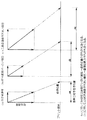
【0268】
例えば、図47の(a)の場合の着弾位置のずれ量Δaに対して、吐出速度が小さい(b)の場合の着弾位置のずれ量Δbは大きくなり、主走査速度が大きい(b)の場合の着弾位置のずれ量Δcも大きくなる。従って、それら主走査速度、吐出速度や吐出角度毎にドットアライメントを実施しても良く、そのようにすることが実際有効である。
【0269】
図48はプリンタの持つモードないしはヘッドの構成に応じたドットアライメント処理を説明するための説明図である。
【0270】
ここで、「プリンタ1」は、図5に示したような構成を有するプリンタであり、「ヘッド1」または「ヘッド2」を用いることができることを示している。「ヘッド1」および「ヘッド2」は図6に示した形態のヘッドである。「ヘッド1」は同図示の構成を有し、ドットアライメント処理に際しては、各モードに応じてBkドットおよびCドットについてのレジストレーション処理(2ヘッド間の縦・横方向)またはBkドットのレジストレーション処理(往復主走査方向)を行うものとする。「ヘッド2」はBk、LC(薄いシアン)、LM(薄いマゼンタ)のノズル群がインラインに配列された吐出部を有する一方、LCおよびLMのノズル群に対応して並置される形態でそれぞれCおよびMのノズル群等がインラインに配列された吐出部を持つようなヘッドであり、ドットアライメント処理に際しては、各モードに応じてLCドットおよびCドットについてのレジストレーション処理(2ヘッド間の縦・横方向)またはBkドットのレジストレーション処理(往復主走査方向)を行うものとする。
【0271】
「プリンタ2」はモノクロームプリントを行うプリンタであり、Bkインクを吐出するノズル群が配列された「ヘッド3」または「ヘッド4」を用いることができる。
【0272】
また、各ヘッドはいずれも図46に示したような吐出ヒータ部を有し、解像度に応じて大小の吐出量を得ることができる。解像度毎の主走査速度は、例えば、180 ×180 dpiの場合は30インチ/秒、360 ×360 dpiの場合は20インチ/秒、720 ×720 dpiの場合は20インチ/秒、1440×720 dpiの場合は10インチ/秒の如く定めることができる。さらに、ドロップサイズ毎のインク吐出量は、「ヘッド1」および「ヘッド4」については「大」が80pl(ピコリットル)、「小」が40plとし、「ヘッド2」および「ヘッド3」については「大」が40pl、「小」が15plとすることができる。
【0273】
実施形態の調整は、双方向プリント、2ヘッドの横方向および縦方向プリントに対応可能であり、さらに粗調整と微調整との2段階調整を行うことが可能であるが、図48に示すように、プリンタおよびヘッドの構成や、ヘッドの組合わせその他に応じて適宜の調整を実行することができ、さらにそれぞれの解像度、主走査速度や吐出速度毎等に調整を行うことができる。また、プリントヘッドによる取り付け精度や製造上の精度により吐出角度は異なるので、必要なプリントヘッド毎に調整を実施するのが好ましい。
【0274】
そして、各モード毎に決定される調整値をそれぞれEEPROM等の不揮発性のメモリ(例えば図9のコントローラ100の構成に付加することができる)に記憶しておく。このように、プリントモード毎に1度だけのドットアライメントを実施し、これを保存しておくことにより、プリントモードに応じて使用する調整値を読み出すことで、それぞれのモード毎に最適な着弾位置の調整が行われたプリントが可能になる。
【0275】
なお、図48の記載内容は数値も含めて例示であって、本発明がこれに限定されないのは言うまでもない。
【0276】
次に、実際の調整パターンを例示する。
【0277】
図49は調整パターンの一例を示し、図45の基本的処理手順を応用した処理の過程で形成・利用されるものである。図示のパターンはB5版(182mm(2580ドット)×257mm(3643ドット))のサイズに対応して形成され、 図45のステップS103のようなセンサキャリブレーションで形成されるパッチ、
ステップS104のような2ヘッド間縦方向粗調整処理で形成される360×360dpiのパッチ群、
ステップS105のような双方向プリント粗調整処理で形成される360×360dpiのパッチ群(−4から+4まで1ドット刻みのずらしを行って形成した9パッチ)、
ステップS107のような双方向プリント微調整処理で形成される360×360dpiのパッチ群(−1から+1まで0.5ドット刻みのずらしを行って形成した5パッチおよびその反転パターンの5パッチ)、および同じく180×180dpのiパッチ群、
ステップS105のような双方向プリント粗調整処理で形成される720×720dpiのパッチ群(−4から+4まで1ドット刻みのずらしを行って形成した9パッチ)、
ステップS108のような2ヘッド間横方向粗調整処理で形成される360×360dpiのパッチ群(−4から+4まで1ドット刻みのずらしを行って形成した9パッチ)、
ステップS109のような2ヘッド間横方向(特に往方向)微調整処理で形成される360×360dpiのパッチ群(−1から+1まで0.5ドット刻みのずらしを行って形成した5パッチおよびその反転パターンの5パッチ)、および同じく2ヘッド間横方向(復方向)微調整処理で形成される360×360dpiのパッチ群、同じく2ヘッド間横方向(往復各方向)の微調整処理で形成される180×180dpi、720×720dpi、1440×720dpiの各パッチ群(反転パターン共)、
が頁頭から形成され、末尾にステップS111のような処理で形成される確認パターンが付加されている。
【0278】
ここで示した調整パターンは様々なプリントモードに対応したものが含まれているが、例えば、2ヘッド間の調整の入らないシングルヘッドのプリント装置においては2ヘッド間の調整は必要なく、双方向の調整のみを行っても良い。そのプリント装置で使用するであろうプリントモードが含まれていればよいのである。
【0279】
また、各処理で形成される複数のパターン(パッチ)は図示の例では分散的に形成されているが、前述のように、これらは連結または連続して形成されていてもよいものである。すなわち、各処理における各ドット形成位置条件とパターン形成位置との対応づけが確実であれば、複数のパターンを連続した1つのものとしてもよい。また、各処理とそれに応じたパターン形成位置との対応づけが確実であれば、各処理間で連続させてもよい。
【0280】
また、使用するインクの色により、吐出速度が異なる場合はその色毎にドットアライメントを実施して、色毎に最適な着弾位置の調整値を持っていても良いのである。
【0281】
さらに、かかる調整は処理手順が起動されたときにプリント装置の持つすべてのモードについて一括して行われるものでもよく、ユーザ等の選択に応じて指定されたモードについてのみ行われるようにしてもよい。
【0282】
また、調整処理の起動についても、プリンタ本体に設けた起動スイッチ等の操作や、ホスト装置のアプリケーションを通じた指示によるものとするほか、例えばプリント装置各部やヘッドの経時変化を考慮し、タイマ等の管理手段を用いて、長期間調整が行われていなかった場合に調整処理を起動もしくはこれを促すものとすることもできる。また、ヘッドカートリッジ1000が交換された場合にも調整処理を起動もしくはこれを促すようにすることができる。
【0283】
7.マニュアル調整等
(7.1)マニュアル調整
次に、自動ドットアライメントシーケンスが実施できない場合に行うマニュアル調整(図30または図45の処理手順におけるステップS119)について述べる。
【0284】
実施形態の装置では光学センサを用いて濃度の検出を行っているので、光学センサが電気的に動作しない場合、もしくは光学的に動作できない場合等にはその他のドットアライメント手段が必要になる。この場合は、マニュアル調整を実施する。マニュアル調整に移行する条件について説明する。
【0285】
まず、光学センサを用いるためには、キャリブレーションを行うが、その際得られたデータが明らかに使用可能範囲外のものである場合には、キャリブレーション・エラーとし、ドットアライメント動作を中止する。例えば、光学センサのLEDの出力が小さすぎて測定物を照射する光量が少なすぎる場合、フォトトランジスタの寿命などにより検出能力が低下して十分な出力が得られない場合、外光の進入などによりフォトトランジスタが検知する反射光があまりに大きすぎる場合等が、光学センサが正常に動作できない場合である。
【0286】
この場合にはその状態のステータスをホストコンピュータに通信して、アプリケーションを介してエラーであることを表示する。さらに、マニュアル調整を実施するように表示して実行を促す。または、キャリブレーション・エラーを検知した場合もドットアライメント動作を中止して、給紙されているプリント媒体上にマニュアル調整の実施を促すプリントを行っても良い。
【0287】
マニュアル調整では、1ドットの罫線パターンを用いる。プリント媒体に第1のプリントで基準となる罫線パターンをプリントし、相対位置条件の異なる複数の罫線(ずらし量の異なる罫線)を第2のプリントでプリントする。このプリントされたものをユーザが見て、どの条件が最も最適なのか判断するのである。従って、判断しやすいように、1ドット罫線を用い、最も着弾位置が合っている位置を実際のドットの位置で見ることができるようにする。
【0288】
マニュアル調整には粗調整と、その後に行われる微調整が含まれる。
【0289】
マニュアル調整の粗調整においては、プリント装置およびプリントヘッドが持っている着弾位置の公差範囲に応じた罫線パターンを用いる。例えば、公差精度が±4ドットである場合の粗調整は図50(A)のようになる。
【0290】
図50(A)では、基準線とずらし線とをそれぞれ調整対象となるプリント手段でプリントを行うものとする。また、ずらす量が丁度0のときに着弾位置が合うものとして例示してある。
【0291】
このようなパターンを見て、ユーザがどの条件が最も着弾位置が合っている(レジストレーションが合っている)かを判断して、その調整値をプリント装置本体に入力するか、ホスト装置上(プリンタドライバのメニュー等)から入力するかして、本体に記憶させる。
【0292】
さらに、より高い精度で調整を行うために、図50(B)のようなパターンをプリントして、微調整を実施する。
【0293】
図50(B)では、0.5ドット単位で調整しているが、本体が有する調整能力(調整解像度、調整精度)に応じて選択できる。そして、粗調整と同様に、ユーザがどの条件が最も着弾位置が合っている(レジストレーションが合っている)かを判断して調整を行う。より高い精度で調整を行う微調整では、粗調整である程度着弾位置が合っているという仮定で実施できるものである。粗調整の前提がなければ、基準線とずらし線の位置は全く異なる点でプリントされてしまう場合がある。このような単純な1つの罫線でドットアライメントを行う場合の原理的なものであり、1ポイントのみが調整値となる。
【0294】
(7.2)マニュアル調整と自動調整との差異
これに対して、上述した自動ドットアライメントは、反射濃度(もしくは光学センサの出力)を測定し、その値から調整値を求めるため、マニュアル調整のように、粗調整を実施しなければ、微調整が実施できないようなことはない。
【0295】
まず、自動ドットアライメントで用いる画像パターンは、反射濃度を測定するためのものであり、例えば図37のような第1のプリント、第2のプリントでそれぞれ同じ幅のパターンがプリントされる。最終的には、パッチ(100%のベタパターンあるいは、必要に応じてある程度間引いたパターン)をプリントすることになる。これを光学センサを用いて、プリントドットの位置を見るのではなく、その反射濃度を見るのである。そしてこの反射濃度の特性から着弾位置の最適な調整点を割り出すのである。
【0296】
図37および図39に示した調整用のパターンを用いた場合について考える。
【0297】
まず、図37のような4ドットで構成されるパターンを調整範囲以上にずらした場合の反射濃度は図51(A)のようになる。
【0298】
パッチはそれぞれ横方向に連続した4ドットの2つのパターン(第1のプリントと第2のプリント)で構成されるために、調整範囲以上に相互の位置をずらした場合には、+4から−4の幅(8ドット分)を1つの周期として、その中で最大または最小値が存在し、その周期で全く同じの濃度特性が繰り返されるのである。すなわち、特性は三角関数的挙動を示し、Acosθで表すことができる(Aは振幅の2倍すなわち最大濃度と最小濃度の差であり、nはずらしドット量、mを公差精度の幅、公差範囲とすると、θ=2πn/mで表すことができる。)つまり、この自動ドットアライメント処理では、単純に反射濃度を見るために、濃度から考えられる調整点(例えば、反射濃度が最大となる点を調整値とした場合には、上記の図で+8、0、−8の3つのポイントが調整値となる)は複数存在することになる。ただプリント装置およびプリントヘッドが有する着弾位置の公差精度は有限である。例えば、上記のように公差精度が±4ドットである場合はその範囲内には濃度の最大値および最小値がそれぞれあり、1周期分が含まれる。逆に言えば、プリント装置およびプリントヘッドが有する着弾位置の公差精度に応じて粗調整に用いるパターンの幅を決定する(2つのパターンで公差範囲より大きくする)ことにより、必ず上記の関係が成り立つ。
【0299】
このようにして、調整精度にもよるが1ドット単位で調整していれば、この濃度特性から少なくとも±1ドット以内の精度でドットアライメントを実施できる。
【0300】
さらに、微調整において、図39のような1ドットで構成されるパターンを調整範囲以上にずらした場合は図51(B)のようになる。
【0301】
図37の場合と同様に、パッチはそれぞれ1ドットの2つのパターン(第1のプリントと第2のプリント)で構成されるために、調整範囲以上に相互の位置をずらした場合には、+1から−1の幅(2ドット分)を1つの周期として、その中で最大または最小値が存在し、その周期で全く同じの濃度特性が繰り返される。
【0302】
ここで、ドットアライメントについて考えると、濃度から考えられる調整点(例えば、反射濃度が最大となる点を調整値とした場合には、上記の図で+2、0、−2の3つのポイントが調整値となる。実際には細かい刻みの解像度になる)は複数存在することになる。この時点では、着弾位置の調整点は3つのポイントのどれでも良い。微調整は、レンジで1ドット以内の調整を行うものであるからである。
【0303】
粗調整で±1ドット以内に調整している結果から、上記3つのポイントの中で最適なポイントがどこであるかは判別することができる。
【0304】
粗調整はプリント装置およびプリントヘッドが有する着弾位置の公差精度の範囲内を粗く調整する方法である一方、微調整はプリント装置が取り得る最高精度で調整を行う方法であり、両者は調整範囲、調整単位が異なるものである。
【0305】
そして、その順番を問うものではなく、粗調整、微調整の順番で行っても、微調整、粗調整の順番で行っても構わない。調整単位が異なり、それぞれの特性に相互に関与しないからである。また、上記のような周期特性を有することに起因する。この点が通常のマニュアル調整と最も異なる点である。そしてそのように調整範囲、調整単位が異なる両者を組み合わせて用いることによって、プリント媒体の浪費を伴うことなく迅速かつ正確に調整値を得ることができる。
【0306】
以上のように、マニュアル調整と自動ドットアライメントで用いる調整パターンは全く異質のものである。
【0307】
本発明が適用されるプリント方法もしくはプリント装置は、この特性の異なる2つの調整パターンを有することを特徴として、必要に応じてその調整パターンを使い分けることが可能である。前述のように、光学センサが電気的に動作しなかったり、外光などの影響で光学的に使用できなかったりする場合に、マニュアル調整を用いることで、着弾位置の調整が可能になるのである。
【0308】
8.吐出量変調を伴う双方向プリントによる画像形成を行う場合の調整
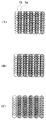
ところで、吐出されるインク量が異なる場合には一般に吐出速度が異なる。例えば、走査速度およびプリント媒体への距離を一定とし、図46のような吐出ヒータ部をもつプリントヘッドにて大小ドロップを吐出するような場合には小ドロップの吐出速度は大ドロップの吐出速度より小さい。従って大小ドロップを混在させて用い、さらに双方向プリントにて画像形成を行うような場合には、大ドロップの双方向プリントについて定めたプリント位置条件を単純に採用しても、大ドロップによる形成ドットに対する小ドロップによる形成ドットのレジストレーションがずれてしまう。
【0309】
図52を用いて大小ドロップによる形成ドットのレジストレーションのずれ等について説明する。
【0310】
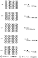
(a)および(b)は、それぞれ、大ドロップにより大ドットを主走査方向に360dpiで形成するときの理想着弾位置、および小ドロップにより小ドット主走査方向にを720dpiで形成するときの理想着弾位置を示している。また、(c)は、大小ドットを混在させ、往方向では小ドロップを大ドロップに先行させて吐出させ、復方向では大ドロップを小ドロップに先行させて吐出させるようにして主走査方向に720dpi(大ドット相互間および小ドット相互間では360dpi)で形成するときの理想着弾位置である。
【0311】
(d)は、プリント媒体の被プリント面に直交する方向(被プリント面が水平方向であれば鉛直方向)からインクを吐出可能なヘッドを用いるプリント装置において、大ドロップの吐出速度が20m/s、小ドロップの吐出速度が18m/s、キャリッジ速度(主走査速度)が20inch/s、吐出口から被プリント面までの距離が1.4mmであるときに、(c)と同様のドット形成を行った結果を示している。この場合、小ドロップによる形成ドットは、理想的な着弾位置ないしは隣り合うべき大ドロップによる形成ドットに対し、主走査方向に約5μmずれた状態となる。そして、大ドロップについて最適なプリント位置条件を定める一方、往方向では小ドロップを大ドロップに先行させて吐出させ、復方向では大ドロップを小ドロップに先行させて吐出させるようにすると、往方向では右、復方向では左にそれぞれ約5μmのずれが生じるので、往復双方向の小ドロップ間でのプリント位置ずれ量は10μm程度となる。
【0312】
(e)は、小ドロップの吐出速度が10m/sであること以外は(d)と同じ条件でドット形成を行った結果を示している。この場合はプリント装置としての動作上、小ドロップによる形成ドットは、大ドロップによる形成ドットに対し、主走査方向に約35μmずれて重なりあった状態となる。そして、大ドロップについて最適なプリント位置条件を定める一方、往方向では小ドロップを大ドロップに先行させて吐出させ、復方向では大ドロップを小ドロップに先行させて吐出させるようにすると、往復双方向で形成された小ドット間の着弾位置ずれ量は70μmとなる。
【0313】
(f)は、往復両方向について小ドロップを大ドロップに先行させて吐出させるようにしたこと以外は(e)と同じ条件でドット形成を行った結果を示している。この場合、往復双方向の小ドロップ間でのプリント位置ずれ量は約35μm程度となる。また、往復双方向の大ドロップ間でもプリント位置ずれが生じ、その量は約35μmとなる。
【0314】
(g)は、(f)において復方向のプリント位置を復路主走査方向とは反対に35μm補正したものである。この場合、大小ドロップともに往復双方向のプリント位置ずれ量はほぼ0μmである。
【0315】
吐出角度、大小ドロップの速度比、主走査速度、吐出口から被プリント面までの距離などの要因による双方向プリントでの大小ドロップ間の理想着弾点のずれ量が10μm程度以下であれば、人間の目に感じられる「ざらつき感」はさほどなく、従って良好な品位のプリント物が得られると考えられる。
【0316】
従って、双方向プリントでの着弾点のずれ量が10μm以下の場合には、往方向では小ドロップを大ドロップに先行させて吐出させ、復方向では大ドロップを小ドロップに先行させて吐出させるようにするとともに、その際のプリント位置条件は一方(例えば大ドロップ)を用いる双方向プリントについて上述のようにして得た最適なプリント位置条件を採用することができる。
【0317】
しかし位置合わせ条件は、大小ドットを併用する実際のプリントに近いパターンから決定することもできる。
【0318】
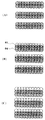
図53および図54は大小ドットによるプリントパターンから位置合わせ条件を決定する態様の一例の説明図であり、上述と同様の粗調整(図53)と微調整(図54)とを含んでいる。
【0319】
粗調整にて図53(A)のようなレジストレーション一致パターンを得るために、図37とほぼ同様の手順にて大小ドロップを用いた基準ドットを往走査プリントで形成し、位置合わせ条件を変えてプリントを行うずらしドットを復走査プリントで形成する。すなわち、無調整でプリントを行った場合をずらし量:0ドットとし、復走査における+方向および−方向の所定ドット数の範囲内のずらしを行って各パターンを形成する(図53(B)および(C))。
【0320】
そして図38について説明したと同様に、双方向プリントを行う場合の調整値(粗調整値)を得ることができる。
【0321】
次に、双方向プリントにおけるプリント位置合わせのより細かい調整精度で微調整を実施するに際しては、図39と同様の処理を行うこともできるが、図40〜図43で説明したのと同様の処理を行って調整精度を高めることができる。
【0322】
すなわち、図54に示すように、粗調整で求められた位置条件を採用して双方向プリントで得たパターン(Ai)に対し、それぞれ+方向および−方向に、復走査ドットの着弾位置の位置合わせ条件(ドットずらし量)を変えて形成したパッチ群(パターン(Aii )および(Aiii))の濃度変化の特性と、当該各位置合わせ条件毎に、基準となるドットに対して線対称となる位置に復走査ドットを形成することによって得たパッチ群(パターン(Bi)〜(Biii))の濃度変化の特性との交点を、ドットの着弾位置が合っている調整位置として求めることができる。
【0323】
このように、双方向プリントでの着弾点のずれ量が10μm以下の場合に、往方向では小ドロップを大ドロップに先行させて吐出させ、復方向では大ドロップを小ドロップに先行させて吐出させるようにするとともに、大小ドットを併用する実際のプリントに近いパターンから位置合わせ条件を決定することもできる。
【0324】
また、双方向プリントでの理想着弾点のずれ量が10μmより大きい場合には、往復双方向ともに同じ順序(小ドロップを大ドロップに先行させる)で吐出を行わせるように定めるとともに、図53(A)〜(C)および図54とそれぞれ同様の図55(A)〜(C)および図56の処理によりプリント位置条件を求め、復方向については当初の大小ドロップの双方向着弾点ずれ量に対応した分だけ当該復方向とは逆の方向にドット形成位置がシフトするようにすればよい。
【0325】
なお、双方向着弾点ずれ量が図52の(e)のような条件では、大ドロップと小ドロップとは同位置に着弾し、小ドットが大ドットに完全に重なることになる。これによって調整用パターンの濃度変化に影響がないような場合には小ドロップの吐出は必ずしも必要ないが、当該重畳によってドット面積ないし濃度に変化が生じるような場合には両ドロップを用いてパターンを形成することが好ましい。
【0326】
また、双方向着弾点ずれ量はヘッドや装置の仕様(少なくとも大小2種類のドロップの吐出速度や主走査速度、吐出口から被プリント面までの距離など)によって実質的に定まる。従って、プリントヘッド側に電気もしくは電子的、機械的、磁気的、あるいは光学的に自らの情報を提示する手段を設け、一方装置のヘッド取付部分等には当該提示情報を受容する対応手段を設けるとともに、提示情報と自らの仕様とから所要の演算を行って双方向着弾点ずれ量に係るデータを得、大小ドットを混在させるプリント時における位置合わせ処理の要否や補正値などを決定することができる。かかる処理は上述したドットアライメントシーケンスの過程に位置づけてコントローラ100により実施することができ、また双方向着弾点ずれ量を求めるための所要の演算に際しては、図47について説明したような速度ベクトルの合成を勘案すればよい。
【0327】
さらに、本例では複数段階の調整(粗調整と微調整)を行うようにしたが、所望の範囲で単一段階の調整とすることもできる。また、本例では形成パターンから自動的に位置合わせ条件を定める態様について述べたが、手動によってこれを行ってもよい。
【0328】
9.その他
以上の各実施の形態では、プリントヘッドからインクをプリント媒体に吐出して画像を形成するインクジェット方式のプリント装置における例を示したが、本発明はその構成に限定されるものではない。プリントヘッドとプリント媒体とを相対的に移動させて、ドットを形成してプリントを行うものであれば、方式を問わずいずれのプリント装置についても有効である。
【0329】
しかし特にインクジェットプリント方式を用いる場合には、その中でも、インク吐出を行わせるために利用されるエネルギとして熱エネルギを発生する手段(例えば電気熱変換体やレーザ光等)を備え、前記熱エネルギによりインクの状態変化を生起させる方式のプリントヘッド、プリント装置において優れた効果をもたらすものである。かかる方式によればプリントの高密度化,高精細化が達成できるからである。
【0330】
その代表的な構成や原理については、例えば、米国特許第4723129号明細書,同第4740796号明細書に開示されている基本的な原理を用いて行うものが好ましい。この方式は所謂オンデマンド型,コンティニュアス型のいずれにも適用可能であるが、特に、オンデマンド型の場合には、液体(インク)が保持されているシートや液路に対応して配置されている電気熱変換体に、プリント情報に対応していて核沸騰を越える急速な温度上昇を与える少なくとも1つの駆動信号を印加することによって、電気熱変換体に熱エネルギを発生せしめ、プリントヘッドの熱作用面に膜沸騰を生じさせて、結果的にこの駆動信号に一対一で対応した液体(インク)内の気泡を形成できるので有効である。この気泡の成長,収縮により吐出用開口を介して液体(インク)を吐出させて、少なくとも1つの滴を形成する。この駆動信号をパルス形状とすると、即時適切に気泡の成長収縮が行われるので、特に応答性に優れた液体(インク)の吐出が達成でき、より好ましい。このパルス形状の駆動信号としては、米国特許第4463359号明細書,同第4345262号明細書に記載されているようなものが適している。なお、上記熱作用面の温度上昇率に関する発明の米国特許第4313124号明細書に記載されている条件を採用すると、さらに優れたプリントを行うことができる。
【0331】
プリントヘッドの構成としては、上述の各明細書に開示されているような吐出口,液路,電気熱変換体の組合わせ構成(直線状液流路または直角液流路)の他に熱作用部が屈曲する領域に配置されている構成を開示する米国特許第4558333号明細書,米国特許第4459600号明細書を用いた構成も本発明に含まれるものである。加えて、複数の電気熱変換体に対して、共通するスリットを電気熱変換体の吐出部とする構成を開示する特開昭59−123670号公報や熱エネルギの圧力波を吸収する開孔を吐出部に対応させる構成を開示する特開昭59−138461号公報に基いた構成としても本発明の効果は有効である。すなわち、プリント・ヘッドの形態がどのようなものであっても、本発明によればプリントを確実に効率よく行うことができるようになるからである。
【0332】
さらに、プリント装置がプリントできるプリント媒体の最大幅に対応した長さを有するフルラインタイプのプリントヘッドに対しても本発明は有効に適用できる。そのようなプリント・ヘッドとしては、複数プリントヘッドの組合わせによってその長さを満たす構成や、一体的に形成された1個のプリント・ッドとしての構成のいずれでもよい。
【0333】
加えて、上例のようなシリアルタイプのものでも、装置本体に固定されたプリントヘッド、あるいは装置本体に装着されることで装置本体との電気的な接続や装置本体からのインクの供給が可能になる交換自在のチップタイプのプリントヘッド、あるいはプリントヘッド自体に一体的にインクタンクが設けられたカートリッジタイプのプリントヘッドを用いた場合にも本発明は有効である。
【0334】
また、本発明のプリント装置の構成として、プリントヘッドの吐出回復手段、予備的な補助手段等を付加することは本発明の効果を一層安定できるので、好ましいものである。これらを具体的に挙げれば、プリントヘッドに対してのキャッピング手段、クリーニング手段、加圧或は吸引手段、電気熱変換体或はこれとは別の加熱素子或はこれらの組み合わせを用いて加熱を行う予備加熱手段、プリントとは別の吐出を行なう予備吐出手段を挙げることができる。
【0335】
また、搭載されるプリントヘッドの種類ないし個数についても、例えば単色のインクに対応して1個のみが設けられたものの他、プリント色や濃度を異にする複数のインクに対応して複数個数設けられるものであってもよい。すなわち、例えばプリント装置のプリントモードとしては黒色等の主流色のみのプリントモードだけではなく、プリントヘッドを一体的に構成するか複数個の組み合わせによるかいずれでもよいが、異なる色の複色カラー、または混色によるフルカラーの各プリントモードの少なくとも一つを備えた装置にも本発明は極めて有効である。
【0336】
さらに加えて、以上説明した本発明実施の形態においては、インクを液体として説明しているが、室温やそれ以下で固化するインクであって、室温で軟化もしくは液化するものを用いてもよく、あるいはインクジェット方式ではインク自体を30℃以上70℃以下の範囲内で温度調整を行ってインクの粘性を安定吐出範囲にあるように温度制御するものが一般的であるから、使用プリント信号付与時にインクが液状をなすものを用いてもよい。加えて、熱エネルギによる昇温を、インクの固形状態から液体状態への状態変化のエネルギとして使用せしめることで積極的に防止するため、またはインクの蒸発を防止するため、放置状態で固化し加熱によって液化するインクを用いてもよい。いずれにしても熱エネルギのプリント信号に応じた付与によってインクが液化し、液状インクが吐出されるものや、プリント媒体に到達する時点ではすでに固化し始めるもの等のような、熱エネルギの付与によって初めて液化する性質のインクを使用する場合も本発明は適用可能である。このような場合のインクは、特開昭54−56847号公報あるいは特開昭60−71260号公報に記載されるような、多孔質シート凹部または貫通孔に液状又は固形物として保持された状態で、電気熱変換体に対して対向するような形態としてもよい。本発明においては、上述した各インクに対して最も有効なものは、上述した膜沸騰方式を実行するものである。
【0337】
さらに加えて、本発明インク・ジェットプリント装置の形態としては、コンピュータ等の情報処理機器の画像出力端末として用いられるものの他、リーダ等と組合わせた複写装置、さらには送受信機能を有するファクシミリ装置の形態を採るもの等であってもよい。
【0338】
【発明の効果】
本発明によれば、相互のドット形成位置調整が行われるべき往路、復路のそれぞれの第1のプリントおよび第2のプリント、もしくは複数のプリントヘッドそれぞれのプリントの第1 のプリント、第2のプリントにおいて、プリントドットの着弾位置の最適な調整値を求めることが可能になる。これにより、大小少なくとも2種類のドットを混在させた場合を含めて着弾位置のずれない双方向プリント、もしくは複数のプリントヘッドを用いたプリントを行うことができるプリント方法およびプリント装置を提供することができる。
【0339】
また、画像形成上の問題や操作性上の問題を発生させずに、高速で且つ高画質の画像のプリントを行いうる装置ないしシステムを低コストで実現することができる。
【図面の簡単な説明】
【図1】ドットマトリクスプリントの原理を説明するための説明図である。
【図2】ドットマトリクスプリントにおいて生じうる濃度ムラ発生の問題点を説明するための説明図である。
【図3】図2において説明した濃度ムラの発生を防止するためのマルチ走査プリントの原理を説明するための説明図である。
【図4】(A)〜(C)はマルチ走査プリントにおいて採用される千鳥・逆千鳥プリントを説明するための説明図である。
【図5】本発明の一実施形態に係るインクジェットプリント装置の概略構成例を示す斜視図である。
【図6】(A)および(B)は、それぞれ、図5に示すヘッドカートリッジの構成例およびその吐出部の構成例を示す斜視図である。
【図7】図6の吐出部において採用されるヒータボードの構成例を示す斜視図である。
【図8】図5の装置において採用される光学センサを説明するための模式図である。
【図9】本発明の一実施の形態に係るインクジェットプリント装置における制御回路の概略構成を示すブロック図である。
【図10】図9におけるゲートアレイないしヒータボードの電気的構成例を示すブロック図である。
【図11】ホスト装置からプリント装置内部でのプリントデータの流れを説明するための模式図である。
【図12】データ転送回路の構成例を示すブロック図である。
【図13】本発明のドットアライメント処理を説明するために、当該処理に使用可能なプリントパターンを示す模式図であり、(A)はプリント位置が合っている状態、(B)は少しずれた状態、(C)はさらにずれた状態でプリントされたときのドットを示す模式図である。
【図14】本発明のドットアライメント処理を説明するために、当該処理で用いることのできるプリント位置合わせのためのパターンを説明する図である模式図であり、(A)はプリント位置が合っている状態、(B)は少しずれた状態、(C)はさらにずれた状態でプリントされたときのドットを示す模式図である。
【図15】プリントパターンにおいてプリント位置がずれた量と反射光学濃度との関係を示す線図である。
【図16】図15の関係を用いてドットアライメント処理を実行するための制御手順の一例を示すフローチャートである。
【図17】本発明のドットアライメント処理を説明するために、当該処理において形成可能なプリントパターンをプリント媒体にプリントした状態を示す模式図である。
【図18】図17のプリントパターンに対するプリント位置合わせ条件の決定の方法を説明するための図である。
【図19】測定された光学反射率とプリント位置パラメータとの関係を示す図である。
【図20】本発明のドットアライメント処理で用いることのできるプリント位置合わせのためのパターンの他の例を説明する図である模式図であり、(A)はプリント位置が合っている状態、(B)は少しずれた状態、(C)はさらにずれた状態でプリントされたときのドットを示す模式図である。
【図21】本発明のドットアライメント処理で用いることのできるプリント位置合わせのためのパターンのさらに他の例を説明する図である模式図であり、(A)はプリント位置が合っている状態、(B)は少しずれた状態、(C)はさらにずれた状態でプリントされたときのドットを示す模式図である。
【図22】本発明のドットアライメント処理で用いることのできるプリント位置合わせのためのパターンのさらに他の例を説明する図である模式図であり、(A)はプリント位置が合っている状態、(B)は少しずれた状態、(C)はさらにずれた状態でプリントされたときのドットを示す模式図である。
【図23】本発明のドットアライメント処理で用いることのできるプリント位置合わせのためのパターンのさらに他の例を説明する図である模式図であり、(A)はプリント位置が合っている状態、(B)は少しずれた状態、(C)はさらにずれた状態でプリントされたときのドットを示す模式図である。
【図24】ドットアライメント処理を実行するための制御手順の他の例を示すフローチャートである。
【図25】複数ヘッド間の主走査方向プリント位置合わせに用いることのできるプリントパターンの一例のドット間距離による特性を説明するための模式図であり、(A)はプリント位置が合っている状態、(B)は少しずれた状態、(C)はさらにずれた状態でプリントされたときのドットを示す模式図である。
【図26】複数ヘッド間の主走査方向プリント位置合わせに用いることのできるプリントパターンの好適例のドット間距離による特性を説明するための模式図であり、(A)はプリント位置が合っている状態、(B)は少しずれた状態、(C)はさらにずれた状態でプリントされたときのドットを示す模式図である。
【図27】図25および図26におけるプリントパターンのドット間距離に応じた反射光学濃度の特性を説明するための図である。
【図28】複数ヘッド間の副走査方向プリント位置合わせに用いることのできるプリントパターンの好適例のドット間距離による特性を説明するための模式図であり、(A)はプリント位置が合っている状態、(B)は少しずれた状態、(C)はさらにずれた状態でプリントされたときのドットを示す模式図である。
【図29】図28におけるプリント吐出口のずれ量と反射光学濃度との関係を示す図である。
【図30】本発明で用いることのできる自動ドットアライメント処理の全体アルゴリズムの一例を示すフローチャートである。
【図31】所定領域に対するインク打込み率を変化させた場合の反射率の関係を示す線図である。
【図32】反射率が異なる測定対象の反射濃度を、実施形態で用いる光センサの発光側の電気信号を変化させて測定した結果を示す線図である。
【図33】光センサの理想的な感度特性を示す線図である。
【図34】図30のアルゴリズムにおいて採用できるセンサキャリブレーション処理の一つの例を説明するための線図である。
【図35】図30のアルゴリズムにおいて採用できるセンサキャリブレーション処理の他の例を説明するための線図である。
【図36】図30のアルゴリズムにおいて採用できるセンサキャリブレーション処理のさらなる例を説明するためのフローチャートである。
【図37】図30のアルゴリズムにおいて採用できる双方向プリントに対するプリント位置合わせの粗調整処理例を説明するための模式図である。
【図38】図37の粗調整によって調整値を得る態様を説明するための線図である。
【図39】図30のアルゴリズムにおいて採用できる双方向プリントに対するプリント位置合わせの微調整処理例を説明するための模式図である。
【図40】図30のアルゴリズムにおいて採用できる双方向プリントに対するプリント位置合わせの微調整処理の他の例を説明するための前提とする模式図である。
【図41】図30のアルゴリズムにおいて採用できる双方向プリントに対するプリント位置合わせの微調整処理の他の例に係るプリントパターンの特性を説明するための線図である。
【図42】図30のアルゴリズムにおいて採用できる双方向プリントに対するプリント位置合わせの微調整処理の他の例に係るプリントパターンを示す模式図である。
【図43】図30のアルゴリズムにおいて採用できる双方向プリントに対するプリント位置合わせの微調整処理の他の例に係るプリントパターンであり、図42の反転パターンを示す模式図である。
【図44】プリント位置合わせ処理に用いるプリントパターンを形成するインクの選定を説明するための線図である。
【図45】本発明で用いることのできる自動ドットアライメント処理の全体アルゴリズムの他の例を示すフローチャートである。
【図46】異なるインク吐出量を得るために採用できるプリントヘッドのインク吐出部の構成例を示す模式図である。
【図47】主走査速度およびインク吐出速度に応じたインク着弾位置のずれを説明するための模式図である。
【図48】プリント装置の持つモードに応じたドットアライメント処理を説明するための説明図である。
【図49】ドットアライメント処理で形成ないしは利用されるプリントパターンの一例を示す説明図である。
【図50】(A)および(B)は、それぞれ、手動によるドットアライメントの粗調整および微調整を説明するための説明図である。
【図51】(A)および(B)は、それぞれ、自動ドットアライメントの粗調整および微調整を説明するための説明図である。
【図52】大小ドロップを混在させた双方向プリント時における形成ドットのレジストレーションのずれ等を説明するための図である。
【図53】(A)〜(C)は、大小ドロップの着弾位置ずれが比較的小さい場合における双方向プリント時に対する位置合わせの粗調整の一例を説明するための図である。
【図54】大小ドロップの着弾位置ずれが比較的小さい場合における双方向プリント時に対する位置合わせの微調整の一例を説明するための図である。
【図55】(A)〜(C)は、大小ドロップの着弾位置ずれが比較的大きい場合における双方向プリント時に対する位置合わせの粗調整の一例を説明するための図である。
【図56】大小ドロップの着弾位置ずれが比較的大きい場合における双方向プリント時に対する位置合わせの微調整の一例を説明するための図である。
【符号の説明】
1 プリントヘッド
2 キャリッジユニット
3 キャリッジユニットホルダ
5 フレキシブルケーブル
6 キャリッジモータ
7 キャリッジベルト
8 プリント媒体
8′ ガイドシャフト
9 フォトカプラ
10 遮光板
12 回復系を含むホームポジションユニット
13 排出ローラ
14 ラインフィードユニット
15 ブラックインク収納インクタンク
16 カラーインク収納タンク
19 電気接点部
21 吐出口面
22 吐出口
23 共通液室
24 液路
25 電気熱変換体
30 反射型光学センサ
100 コントローラ
101 MPU
103 ROM
104 ゲートアレイ
105 RAM
107 不揮発性メモリ
110 ホスト装置
112 インタフェース
122 電源スイッチ
124 プリント開始指示スイッチ
126 回復スイッチ
127 レジストレーション調整起動スイッチ
129 レジストレーション調整値設定入力部
130 センサ群
150 ヘッドドライバ
162 搬送(副走査)モータ
820 操作部
1000 ヘッドカートリッジ[0001]
BACKGROUND OF THE INVENTION
The present invention relates to a method for adjusting a dot formation position in dot matrix recording and a printing apparatus using the method, for example, dot alignment when performing bidirectional printing in forward scanning and sub-scanning, and using a plurality of print heads. The present invention relates to a dot forming position adjustment method applicable to print position alignment between heads when printing is performed, and a printing apparatus using the method.
[0002]
[Background]
In recent years, OA devices such as relatively inexpensive personal computers and word processors have become widespread, and various recording devices for printing out information input by these devices, speed-up technology for the devices, and technology for improving image quality have rapidly increased. It has been developed. Among recording apparatuses, a serial printer using a dot matrix recording (printing) method has attracted attention as a recording apparatus (printing apparatus) that realizes high-speed or high-quality printing at low cost. For such a printer, a technique for performing high-speed printing includes, for example, a bidirectional printing method, and a technique for performing high-quality printing includes, for example, multipass.
[0003]
(Bidirectional printing method)
As a technology for speeding up, it is considered to increase the number of print elements in a print head having a plurality of print elements and to improve the scan speed of the print head. However, the print head performs bidirectional print scanning. This is also an effective method.
[0004]
Normally, the printing apparatus does not have a simple proportional relationship because there is time for paper feeding and paper ejection, but bidirectional printing can obtain a printing speed approximately twice that of unidirectional printing.
[0005]
For example, a print density of 360 dpi and an A4 size print medium using a print head in which 64 discharge ports are arranged in a direction different from the print scan (main scan) direction (for example, the sub scan direction which is the print medium feed direction) When printing in portrait orientation, printing can be completed in about 60 print scans. However, in unidirectional printing, all the print scans are performed only when moving in one direction from a predetermined scan start position. In addition, since non-print scanning in the reverse direction for returning from the scan end position to the scan start position is involved, approximately 60 reciprocations are performed. On the other hand, in bidirectional printing, printing is completed in about 30 reciprocating print scans, and printing can be performed at a speed close to about twice. Therefore, it can be said that this is an effective method for improving the printing speed. .
[0006]
In order to perform such bidirectional printing, in order to align the dot formation positions of the forward path and the backward path (for example, the ink dot landing position in the case of an inkjet printing apparatus), position detection means such as an encoder is used, and the detection position In many cases, the print timing is controlled based on this. However, since the construction of such a feedback control system also causes an increase in the cost of the printing apparatus, it has been considered difficult to realize this with a relatively inexpensive printing apparatus.
[0007]
(Multi-scan printing method)
Next, a multi-scan printing method will be described as an example of a high image quality technology.
[0008]
When printing is performed using a print head having a plurality of print elements, the quality of the printed image largely depends on the performance of the print head alone. For example, in the case of an ink jet print head, there are slight differences that occur in the print head manufacturing process, such as variations in the shape of the ink discharge port and the elements for generating energy used for ink discharge, such as an electrothermal converter (discharge heater). This affects the discharge amount of each discharged ink and the direction of the discharge direction, and can cause image quality deterioration as density unevenness of the finally formed image.
[0009]
A specific example will be described with reference to FIGS. In FIG. 1A,
[0010]
However, in actuality, as described above, in the
[0011]
Therefore, the following method has been devised as a countermeasure against this density unevenness. The method will be described with reference to FIGS.
[0012]
In this method, the
[0013]
When such a printing method is used, even if the
[0014]
When performing such printing, the first scan and the second scan divide the image data according to a certain arrangement (mask) so as to make up for each other. Usually, this image data arrangement (decimation pattern) is As shown in FIG. 4, it is most common to use a pixel that has exactly a staggered pattern for each vertical and horizontal pixel. In the unit print area (in this case, four pixels), the print is completed by the first scan that forms dots in a staggered pattern and the second scan that forms dots in a reversed staggered pattern. Further, the amount of movement (sub-scanning amount) of the print medium between each scanning is normally set to be constant, and in the case of FIGS. 3 and 4, it is moved equally by 4 nozzles.
[0015]
(Dot alignment)
As another example of the high image quality technology in the dot matrix printing method, there is a dot alignment technology for adjusting the dot landing position. The dot alignment is an adjustment method for adjusting the position at which dots are formed on the print medium by some means, and the conventional dot alignment is generally performed as follows.
[0016]
For example, in the reciprocal printing, in the forward and sub-scan landing position alignment, the ruled lines and the like are printed while changing the relative print position conditions in the reciprocating scan by adjusting the print timing for the forward scan and the sub-scan respectively. Print on media. The user visually observes it, selects the condition that seems to be the best position, that is, the condition that the ruled line etc. is printed without shifting, and inputs it directly to the printing device by key operation etc. Alternatively, the landing position condition is set in the printing apparatus via the application by operating the host computer.
[0017]
Also, when printing between multiple heads in a printing device with multiple heads, each line prints ruled lines and the like on the print medium while changing the relative print position conditions between the multiple heads. To do. In the same way as described above, the user selects the optimum condition for matching the print position, changes the relative print position condition, and sets the print position condition in the printing device for each head by the same means as described above. Was.
[0018]
[Problems to be solved by the invention]
Here, a case where a deviation of the landing positions of dots has occurred will be described.
[0019]
(Problems in forming images by bidirectional printing)
The following problems are caused for bidirectional printing.
[0020]
First, when printing a ruled line (vertical ruled line) in a direction perpendicular to the main scanning direction of the print head, the position of the ruled line printed in the forward path and the ruled line printed in the return path are not aligned, and the ruled line does not become a straight line. A level difference will occur. This is a so-called “ruled line shift”, and can be said to be the most general image disturbance recognized by a general user. Since the ruled lines are often formed in black, it has been generally recognized as a problem when forming a monochrome image, but the same phenomenon occurs in a color image.
[0021]
(Problem when performing image formation by bidirectional printing with ink ejection amount modulation) In the case of an inkjet printing apparatus, the size of the print dots is mainly determined by the amount of ink ejected from the print head. Therefore, if printing is performed using ink dots having a relatively small discharge amount as appropriate, high resolution can be realized. On the other hand, when performing so-called “solid” printing, the discharge amount is relatively large. Printing efficiency can be improved by printing with the ink dots.
[0022]
In general, in the case of an ink jet printing apparatus that performs printing by ejecting ink as, for example, drops while scanning a print head, the landing position of the drop is affected by a scanning speed component. In addition, when the amount of ink to be ejected is different, the ejection speed is generally different. For example, when large and small drops are mixed and image formation is performed by bidirectional printing, the large drop bidirectional printing is performed. Even when the optimum print position condition is determined, the registration of the small drop with respect to the large drop is shifted.
[0023]
When such a shift occurs, an image that can give an overall rough impression when a uniform halftone pattern is printed is formed, and may be recognized as an unpleasant pattern by some users.
[0024]
(Problems in image formation using multiple heads)
Consider a problem when a dot landing position shift occurs between a plurality of heads in a printing apparatus having a plurality of heads.
[0025]
When printing an image, an image is often formed by combining several kinds of colors. The most common is to use four colors obtained by adding black to the three primary colors of yellow, magenta, and cyan. is there. When using multiple print heads for printing these colors, if there is a shift in the landing position between the print heads, a color shift will occur if different colors are printed on the same pixel, depending on the amount of deviation. End up. For example, magenta and cyan are used to form a blue image, but when the dots of both colors overlap, it becomes blue, but when it does not overlap, it does not become blue and each individual color appears. This causes a color shift. Even if this occurs in a part, it does not stand out. However, if this phenomenon occurs continuously in the scanning direction, a band-like color shift of a specific width results in an uneven image. Further, if there is no deviation in the landing positions of dots in an adjacent image area in the same color image, the uniformity and color development differ between adjacent image areas, resulting in an uncomfortable image. Further, this color misalignment is not so noticeable on plain paper, but may be noticeable when a print medium with good color development such as coated paper is used.
[0026]
In addition, when printing different colors on adjacent pixels, if there is a deviation in the dot landing position, a gap, that is, an area that is not covered with ink, is generated, and the ground of the print medium may be seen directly. is there. Since many print media are generally white, this phenomenon is often referred to as “white spots”. This phenomenon is conspicuous in images with strong contrast, and when a black image is formed with a chromatic color as the background, a white gap without ink exists between the black and chromatic colors. The contrast between the two may be noticeable more clearly.
[0027]
(Task)
In order to suppress the occurrence of the above problems, it is effective to perform the dot alignment described above. However, the user must visually check the print result when the landing position alignment conditions are changed, select the optimal landing position alignment conditions, and perform the input work. In order to force the user to make a determination to obtain the position, a setting that is not optimal may be made. Therefore, it is particularly disadvantageous for a user who is unfamiliar with the operation.
[0028]
In addition, since the user has to print an image for adjusting the landing position and make a necessary decision after seeing this, it is necessary to set the conditions, so that the user has to spend at least twice. Therefore, it is not preferable in realizing an apparatus or system with good operability, and it is disadvantageous in terms of time.
[0029]
In other words, an apparatus or system capable of printing high-quality images at high speed without causing the above-mentioned image formation problems and operability problems is opened without using feedback control means such as an encoder. It is highly desirable to achieve this at low cost so that the landing position can be adjusted by a loop.
[0030]
Therefore, the present invention intends to realize a low-cost dot alignment method with excellent operability. Further, the present invention basically detects the optical characteristics of the printed image without forcing the user to make judgments and adjustments, calculates the optimum dot alignment adjustment conditions from the detection results, and sets the adjustment conditions. The purpose is to enable automatic setting and improve the adjustment accuracy.
[0031]
[Means for Solving the Problems]
To that end, the present invention provides: Discharge from one nozzle Can modulate dots in at least two levels With multiple nozzles For a printing apparatus that uses a print head to print an image by forward scanning and backward scanning with different dot formation positions on a print medium, the dot formation position shift between the forward scanning and backward scanning prints. Is a print alignment method for performing a process for adjusting the print position.
A pattern formed by the forward scanning print and the backward scanning print using one of the large and small dots, and the relative dot formation positions of the forward scanning print and the backward scanning print are different from each other. A pattern forming step of forming a plurality of patterns shifted on the print head;
An adjustment value acquisition step for obtaining an adjustment value for adjusting the deviation of the one dot based on the formed plurality of patterns;
A correction step of correcting a deviation in the formation position due to the other dot based on the adjustment value in order to adjust a deviation in the dot formation position between the other forward scanning and backward scanning prints among the large and small dots; Prepared,
In the correction step, the other of the large and small dots, When the adjustment value is applied When the amount of deviation in the backward scanning direction of the dot forming position by the backward scanning print with respect to the dot forming position by the forward scanning print is equal to or less than a predetermined amount, First From the small dot vomit Then start the large dot Is discharged In the backward scanning, from the large dot vomit Then start the small dot Is discharged So that the large and small dots vomit Set the order,
When the amount of deviation is larger than the predetermined amount, the small dot is used in the forward scan and the backward scan. vomit Then start the big dot Is discharged So that the large and small dots vomit Make the order equal, and By making the ejection order of the large and small dots equal, For each of the large and small dots, the large and small dot formation positions by the backward scanning print are equivalent to the amount of deviation in the backward scanning direction of the dot formation positions by the backward scanning print with respect to the dot formation positions by the forward scanning printing. To shift in the direction opposite to the backward scanning direction. Determine the ejection timing of the large dots and the small dots It is characterized by that.
[0032]
The present invention also provides: Discharge from one nozzle Can modulate dots in at least two levels With multiple nozzles A printing apparatus that uses a print head to print an image by forward scanning and backward scanning printing in which dot formation positions are changed on a print medium,
A pattern formed by the forward scanning print and the backward scanning print using one of the large and small dots, and the relative dot formation positions of the forward scanning print and the backward scanning print are different from each other. Pattern forming means for causing the print head to form a plurality of shifted patterns;
An adjustment value acquisition means for obtaining an adjustment value for adjusting a deviation in dot formation position between the forward scanning print and the backward scanning print for the one dot based on the plurality of formed patterns; ,
Correction means for correcting a deviation in the formation position of the other dot based on the adjustment value in order to adjust the deviation in the dot formation position between the other forward scan and the backward scan among the large and small dots; Prepared,
The correcting means is the other of the large and small dots. When the adjustment value is applied When the amount of deviation in the backward scanning direction of the dot forming position by the backward scanning print with respect to the dot forming position by the forward scanning print is equal to or less than a predetermined amount, First From the small dot vomit Then start the large dot Is discharged In the backward scanning, from the large dot vomit Then start the small dot Is discharged So that the large and small dots vomit Set the order,
When the amount of deviation is larger than the predetermined amount, the small dot is used in the forward scan and the backward scan. vomit Then start the big dot Is discharged So that the large and small dots vomit Make the order equal, and By making the ejection order of the large and small dots equal, For each of the large and small dots, the large and small dot formation positions by the backward scanning print are equivalent to the amount of deviation in the backward scanning direction of the dot formation positions by the backward scanning print with respect to the dot formation positions by the forward scanning printing. To shift in the direction opposite to the backward scanning direction. Determine the ejection timing of the large dots and the small dots It is characterized by that.
[0033]
Furthermore, the present invention provides Discharge from one nozzle Can modulate dots in at least two levels With multiple nozzles A printing apparatus that uses a print head to print an image by forward scanning and backward scanning with different dot formation positions on a print medium; and a host apparatus that supplies the image data to the printing apparatus A printing system comprising:
A pattern formed by the forward scanning print and the backward scanning print using one of the large and small dots, and the relative dot formation positions of the forward scanning print and the backward scanning print are different from each other. Pattern forming means for causing the print head to form a plurality of shifted patterns;
An adjustment value acquisition means for obtaining an adjustment value for adjusting a deviation in dot formation position between the forward scanning print and the backward scanning print for the one dot based on the plurality of formed patterns; ,
In order to adjust the deviation of the dot formation position between the other forward scan and reverse scan among the large and small dots, the formation position by the other dot based on the adjustment value The amount of deviation is obtained and the formation position Correction means for correcting the deviation of
The correcting means is the other of the large and small dots. When the adjustment value is applied When the amount of deviation in the backward scanning direction of the dot forming position by the backward scanning print with respect to the dot forming position by the forward scanning printing is equal to or less than a predetermined amount, the formation starts from the small dot in the forward scanning. Next, the large dot is formed, and in the backward scanning, First From the small dot vomit Then start the large dot Is discharged In the backward scanning, from the large dot vomit Then start the small dot Is discharged So that the large and small dots vomit Set the order,
When the amount of deviation is larger than the predetermined amount, the small dot is used in the forward scan and the backward scan. vomit Then start the big dot Is discharged So that the large and small dots vomit Make the order equal, and By making the ejection order of the large and small dots equal, For each of the large and small dots, the large and small dot formation positions by the backward scanning print are equivalent to the amount of deviation in the backward scanning direction of the dot formation positions by the backward scanning print with respect to the dot formation positions by the forward scanning printing. To shift in the direction opposite to the backward scanning direction. Determine the ejection timing of the large dots and the small dots It is characterized by that.
[0034]
In the above, the adjustment value acquisition step or means includes a step or means for measuring each optical characteristic of the plurality of patterns formed by the pattern formation step or means, and an optical characteristic of each of the measured plurality of patterns. And a step or means for obtaining the adjustment value based on the above.
[0035]
Further, it is possible to provide a process or means for executing the pattern formation and the adjustment value acquisition a plurality of times for each different dot alignment accuracy.
[0036]
Here, the step or means for executing the pattern formation and the adjustment value acquisition a plurality of times for each different dot alignment accuracy includes a coarse adjustment step or means for performing the alignment accuracy with dot accuracy, and 1 A fine adjustment step or means performed with accuracy within a dot, and the fine adjustment can be performed after the coarse adjustment, or the coarse adjustment can be performed after the fine adjustment.
[0037]
The pattern forming step or means includes Forward scan Print and Back scan A pattern formed by printing, Forward scan Said to print Back scan Print relative Dot formation Position Shift A plurality of first patterns and second patterns having different directions The shifting Each corresponding to the quantity Multiple Forming the adjustment value obtaining step, measuring each of the optical characteristics of the plurality of first patterns and the optical characteristics of the plurality of second patterns, and measuring the plurality of first From the intersection of the change characteristic of the optical characteristic of the pattern and the change characteristic of the optical characteristic of the plurality of second patterns, Adjustment value Can be obtained.
[0038]
The adjustment value acquisition step or means uses linear approximation or polynomial approximation from the optical characteristic data obtained by the measurement. Before The adjustment value can be calculated.
[0042]
In the above, a calculation step or means for calculating the deviation amount is provided, and the print head is a head that performs printing by ejecting ink from an ejection port, and the calculation step or means forms the large and small dots. The calculation can be performed from each ink discharge speed for scanning, a scanning speed for scanning the print head relative to the print medium, and a distance from the discharge port to the print medium.
[0044]
The head may include a heating element that generates thermal energy that causes film boiling in the ink as energy used to eject the ink.
[0045]
In this specification, “print” (hereinafter sometimes referred to as “print”) is not only for forming significant information such as characters and figures, but also for human beings regardless of significance. Regardless of whether or not it has been made obvious so that it can be perceived, the image, pattern, pattern or the like is widely formed on the print medium, or the medium is processed.
[0046]
Here, the “print medium” refers not only to paper used in a general printing apparatus, but also widely refers to materials that can accept ink, such as cloth, plastic film, metal plate, and the like.
[0047]
Further, the term “ink” should be broadly interpreted in the same way as the definition of “print”, and is applied to a print medium to be used for forming an image, a pattern, a pattern or the like or processing the print medium. Say liquid to get.
[0048]
DETAILED DESCRIPTION OF THE INVENTION
Hereinafter, the present invention will be described in detail with reference to the drawings. Hereinafter, the case where the present invention is applied mainly to an inkjet printing apparatus and a printing system using the inkjet printing apparatus will be described.
[0049]
1. Overview
(1.1) Outline of dot alignment process
In the dot formation position (ink landing position) adjustment (print position adjustment) method and printing apparatus according to the embodiment of the present invention, forward printing and return printing (bidirectional printing) in bidirectional printing in which mutual dot formation position adjustment should be performed Each print (corresponding to the first print and the second print) or a plurality of (two) print heads (first print, second print) is performed at the same position on the print medium. Further, the printing is performed under a plurality of conditions by changing the alignment condition of the relative dot formation position between the first print and the second print. That is, a plurality of print patterns (patches) described later are formed by changing the relative positional conditions of the first and second prints.
[0050]
Then, the density is read using an optical sensor mounted on a main scanning member such as a carriage. That is, the optical sensor on the carriage is moved to a position corresponding to the patch, and the reflected optical density (or the intensity or reflectance of the reflected light) is measured. Then, the condition where the positions of the first and second prints are the best is determined from the relative relationship between these values. That is, an approximate characteristic of the density with respect to the landing position condition is calculated from the relative relationship between the landing position condition and its density. The optimum landing position condition is obtained from the approximate characteristics. The image pattern to be printed at this time is set in consideration of the accuracy of the printing apparatus and the print head. In the first printing, a pattern having a width equal to or greater than the maximum deviation amount of the landing position accuracy predicted from accuracy is printed on the print medium. In the second print, a pattern having the same width is printed under the alignment condition of each landing position. Thereby, the landing position condition can be adjusted with an accuracy equal to or higher than the accuracy of the landing position alignment condition.
[0051]
Further, the first print and the second print are performed in the same manner under a plurality of conditions by changing the alignment condition of the relative landing positions using the landing position conditions once set. The alignment condition in this case is set with higher accuracy than the previous time. In other words, based on the result of alignment by the first dot alignment (coarse adjustment), the combined accuracy is expected to be the maximum displacement, and is equivalent to the maximum displacement amount of the landing position accuracy predicted from the combined accuracy The first print and the second print are performed using a pattern having a width of. Thereby, dot alignment (fine adjustment) with higher accuracy becomes possible.
[0052]
(1.2) Overview of overall algorithm
After the optical sensor is calibrated, coarse adjustment is performed. The adjustment range of the coarse adjustment is determined from the accuracy of the printing apparatus and the print head. Fine adjustment is performed using the landing position alignment conditions determined by the coarse adjustment, and dot alignment is performed with higher accuracy. Fine adjustment is performed within the accuracy of coarse adjustment. Therefore, the adjustment interval can be set more finely because the adjustment range can be narrowed. Further, after the adjustment is completed, a confirmation pattern is printed to confirm whether the dot alignment has been performed correctly, so that the user can confirm whether the landing position is accurately controlled.
[0053]
The range of dot alignment can be determined as appropriate according to the apparatus configuration, the printing mode of the apparatus, and the like. For example, a printing apparatus using a plurality of print heads may perform dot alignment for bidirectional printing and printing between a plurality of heads, and a printing apparatus using only one head may perform dot alignment for bidirectional printing. If one head can eject inks with different color tones (colors and densities), or if different ejection amounts can be obtained, dot alignment is performed for each color tone or each ejection amount. You may do it.
[0054]
Furthermore, as will be described later, the coarse adjustment and the fine adjustment are not necessarily performed in the order described above.
[0055]
(1.3) Confirmation pattern
After the dot alignment is performed, a confirmation pattern is printed using the set landing position conditions to confirm whether the control has been performed reliably or to allow the user to recognize the dot alignment result. To do. Usually, the ruled line pattern is easy to recognize, so the ruled line is printed in each mode such as bidirectional printing, between a plurality of heads, etc., and at each printing speed. Thereby, the user can recognize the result of the performed dot alignment clearly.
[0056]
(1.4) Optical sensor
As the optical sensor used in the embodiment, a color sensor appropriately selected according to the ink color tone or the head configuration used in the printing apparatus can be used. In other words, for example, a color having excellent light absorption characteristics with respect to the color of a red LED or infrared LED is used, and a printing unit corresponding to the color ink is set as an object of dot alignment. From the viewpoint of absorption characteristics, black (Bk) or cyan (C) is preferable, and magenta (M) and yellow (Y) cannot obtain sufficient density characteristics and S / N ratio. Thus, by determining the color to be used according to the characteristics of the LED to be used, it is possible to correspond to each color. For example, by mounting a blue LED, a green LED, etc. in addition to red, dot alignment can be performed for each color (C, M, Y) with respect to Bk.
[0057]
(1.5) Manual adjustment
In the embodiment, automatic dot alignment processing is performed after density detection is performed using an optical sensor. However, other dot alignment processes can be performed in preparation for cases where the optical sensor does not operate favorably. That is, in this case, normal manual adjustment is performed. The conditions for shifting to such manual adjustment will be described.
[0058]
First, calibration is performed when using the optical sensor. If the data obtained at that time is clearly out of the usable range, a calibration error is generated and the dot alignment operation is stopped. The status status is communicated to the host computer and an error is displayed via the application. Further, a display is made to execute manual adjustment, and execution is prompted. Alternatively, when a calibration error is detected, the dot alignment operation may be stopped, and a print requesting manual adjustment may be performed on the fed print medium.
[0059]
Next, disturbance will be described.
[0060]
The optical sensor may malfunction due to the incidence of light from the outside. Therefore, if the reflected light becomes extremely strong during dot alignment, it is assumed that there is disturbance light, and dot alignment is stopped. Then, like the calibration error, the status of the state is communicated to the host computer, and an error is displayed via the application. Further, a display is made to execute manual adjustment, and execution is prompted. Alternatively, when a calibration error is detected, the dot alignment operation may be stopped, and a print requesting manual adjustment may be performed on the fed print medium.
[0061]
Of course, if the sensor error is transient, such as incident incidental disturbance light, the dot alignment process is started again after informing the user to set a time or condition. It can also be done. Further, when an error occurs during execution of one of various print alignment processes corresponding to modes and the like described later, the process can be stopped and another print alignment process can be performed.
[0062]
(1.6) Recovery operation
The recovery operation employed in the embodiment will be described. This means that before performing automatic dot alignment, a series of recovery operations such as suction, wiping, and pre-discharge are always performed to improve or maintain the ink discharge state of the print head. It is.
[0063]
As an operation timing, when there is an execution instruction of automatic dot alignment, a recovery operation is performed before executing the instruction. As a result, a pattern for print alignment can be printed while the ejection state of the print head is stable, and correction conditions for print alignment with higher reliability can be set.
[0064]
The recovery operation is not limited to a series of operations such as suction, wiping, and preliminary discharge, and may be preliminary discharge or preliminary discharge and wiping alone. In this case, it is preferable that the preliminary ejection is set so that preliminary ejection having a larger number of ejections than the preliminary ejection at the time of printing is performed. Further, there is no particular limitation on the combination of the number of suction, wiping, preliminary discharge and the operation order.
[0065]
Further, it may be determined whether or not it is necessary to execute suction recovery before automatic dot alignment control according to the elapsed time from the previous suction recovery. In this case, it is first determined whether or not a predetermined time has elapsed since the previous suction operation immediately before performing automatic dot alignment. If the suction operation is performed within a predetermined time, an automatic dot alignment registration is performed. On the other hand, if the suction recovery motion is not performed within a predetermined time, automatic dot alignment can be performed after a series of recovery operations including suction recovery.
[0066]
In addition, it is determined whether or not the print head has ejected more ink than the predetermined number from the previous suction recovery. The automatic dot alignment may be performed from the beginning, and furthermore, both the elapsed time and the number of ink ejections may be used as judgment materials, and when either of them reaches a predetermined value, the suction recovery may be performed. .
[0067]
By doing so, it is possible to prevent excessive suction recovery, thereby contributing to saving ink consumption and reducing ink discharge to the waste ink processing unit, and automatic dots. The recovery operation before alignment can be performed efficiently.
[0068]
In addition, the recovery conditions are made variable according to the elapsed time from the previous suction recovery or the number of ink ejections.For example, when the elapsed time is short, only preliminary ejection and wiping are performed without performing the suction operation. If it is long, the recovery condition may be changed such that suction recovery is further inserted.
[0069]
2. Configuration example of printing device
(2.1) Mechanical configuration
FIG. 5 is a perspective view showing an example of the configuration of a color ink jet printing apparatus suitable for implementing or applying the present invention. FIG. 5 shows a state where the front cover is removed and the inside of the apparatus is exposed.
[0070]
In the figure, 1000 is a replaceable head cartridge, and 2 is a carriage unit for detachably holding the ink jet cartridge.
[0071]
A
[0072]
[0073]
FIG. 6A is a perspective view showing details of the
[0074]
In this example, the Bk ink ejection unit in which nozzles for ejecting Bk ink are arranged, and the nozzle groups for ejecting Y, M, and C inks, respectively, are integrated and correspond to the Bk ejection port arrangement range inline. The head in which the color ink ejection units arranged in parallel are arranged side by side is used.
[0075]
FIG. 6B is a schematic perspective view partially showing the main structure of the
[0076]
In FIG. 6B, a plurality of
[0077]
In this example, a configuration in which a nozzle group for ejecting Bk ink and a nozzle group for ejecting Y, M, and C inks are arranged in one print head is not limited to this form. A print head having a nozzle group for ejecting Bk ink and a print head having a nozzle group for ejecting Y, M, and C inks may be independent, or a head cartridge may be independent. Further, a head cartridge having a configuration in which the nozzle groups of the respective colors are independent may be used. The combination of the print head and the head cartridge is not particularly limited.
[0078]
FIG. 7 shows a schematic diagram of the heater board HB of the head used in this example. A temperature control (sub)
[0079]
The figure also shows the positional relationship of the outer peripheral wall section 80f of the top plate that separates into a region where the heater board of the Bk ink ejection section is filled with ink and a region where it is not. The
[0080]
FIG. 8 is a schematic diagram for explaining the reflective
[0081]
As shown in FIG. 8, the reflective
[0082]
(2.2) Configuration of control system
Next, the configuration of a control system for executing print control of the above-described apparatus will be described.
[0083]
FIG. 9 is a block diagram showing an example of the configuration of the control system. In the figure, a
[0084]
The operation unit 820 is a switch group that receives an instruction input from the operator. The
[0085]
The
[0086]
The
[0087]
FIG. 10 is an example of a circuit diagram illustrating details of each unit in FIG. 9. The
[0088]
The
[0089]
The operation of the above control configuration will be described. When a print signal enters the
[0090]
Next, the flow of print data in the printing apparatus will be described with reference to FIG. Print data sent from the
[0091]
In the text buffer TB, print data is held as an intermediate format for one line, and processing for adding a print position, a modification type, a size, a character (code), a font address, and the like of each character is performed. The capacity of the text buffer TB varies depending on each model. The serial printer has a capacity of several lines, and the page printer has a capacity of one page. Further, the print data stored in the text buffer TB is developed and stored in a binarized state in the print buffer PB, and a signal is sent as print data to the print head to perform printing.
[0092]
In this example, the binarized data stored in the print buffer PB is multiplied by a decimation mask pattern at a specific rate, and then a signal is sent to the print head. Therefore, the mask pattern can be set after looking at the data stored in the print buffer PB. Depending on the type of printing apparatus, there is a type in which the print data stored in the reception buffer RB is developed simultaneously with command analysis and written to the print buffer PB without having the text buffer TB.
[0093]
FIG. 12 is a block diagram showing a configuration example of the data transfer circuit. Such a circuit can be provided as a part of the
[0094]
A
[0095]
The data transfer circuit shown in FIG. 12 serially transfers 128-bit print data to the
[0096]
The
[0097]
Although this example has been described with four mask register configurations, this may be any other number of mask registers. In this example, the masked transfer data is directly supplied to the
[0098]
3. Aspect of dot alignment (print alignment)
Next, a description will be given of an aspect of print alignment that is the basis of the present embodiment.
[0099]
(3.1) Print alignment in bidirectional printing
FIGS. 13A to 13C are schematic diagrams illustrating examples of print patterns in print alignment in bidirectional printing.
[0100]
13A to 13C,
[0101]
FIG. 13A shows dots when printing is performed in a state where the print positions are the same in the forward scan and the backward scan, FIG. 13B is a state in which the print position is slightly shifted, and FIG. The dots are shown when printed in a shifted state. As is clear from FIGS. 13A to 13C, in this embodiment, complementary dot formation is performed in each reciprocating scan. That is, in the forward scan, dots in odd-numbered rows are formed, and in the backward scan, dots in even-numbered rows are formed. Therefore, the print position is in the state shown in FIG. 13A in which each of the reciprocating dots has a distance corresponding to the diameter of approximately one dot.
[0102]
This print pattern is designed so that the density of the entire print portion decreases as the print position shifts. That is, the area factor is approximately 100% within the range of the patch as the print pattern in FIG. As shown in FIGS. 13B and 13C, as the print position is shifted, the overlap between the forward scanning dots (outlined dots) and the backward scanning dots (hatched dots) increases, and the area is not printed. That is, the area not covered by the dots also spreads. As a result, the area factor decreases, so that on average, the overall density decreases.
[0103]
In the present embodiment, the print position is shifted by shifting the print timing. This can be done by shifting the print data.
[0104]
Although FIGS. 13A to 13C show one dot unit in the scanning direction, an appropriate unit may be set according to the accuracy of registration (print alignment) or the accuracy of registration detection. it can. FIGS. 14A to 14C show the case of a unit of 4 dots, where FIG. 14A shows a state where the printing position is in alignment, FIG. 14B shows a state where the printing position is slightly shifted, and FIG. This is the state of the dot when it is done.
[0105]
The intent of these patterns is to reduce the area factor while the reciprocal print positions deviate from each other. This is because the density of the print portion strongly depends on the change of the area factor. That is, the density increases due to the overlapping of dots, but the increase in the unprinted area has a greater influence on the average density of the entire print section.
[0106]
FIG. 15 shows an outline of the relationship between the shift amount of the print position and the change in the reflection optical density in the print patterns shown in FIGS. 13A to 13C and FIGS. 14A to 14C of the present embodiment. .
[0107]
In FIG. 15, the vertical axis represents the reflection optical density (OD value), and the horizontal axis represents the amount (μm) of displacement of the print position. When incident light Iin35 and reflected light Iref37 of FIG. 7 are used, reflectance R = Iref / Iin and transmittance T = 1−R. The optical density includes a reflection optical density using the reflectance R and a transmission optical density using the transmittance T. In this specification, the reflection optical density is used, and unless there is a particular confusion, the optical density or simply the density. It abbreviates.
[0108]
When the reflection optical density is d, R = 10 -d There is a relationship. Since the area factor is 100% when the amount of print position deviation is 0, the reflectance R is the smallest. That is, the reflection optical density d is maximized. The reflected optical density d decreases even if the print position is relatively shifted in any of the + and-directions.
[0109]
FIG. 16 shows a schematic flowchart of the print alignment process.
[0110]
As shown in FIG. 16, first, a predetermined print pattern is printed (step S1). Next, the optical characteristic of this print pattern is measured by the optical sensor 30 (step S2). Based on the optical characteristics obtained from the measured data, an appropriate print position condition is obtained (step S3). For example, as shown in FIG. 18 (described later), a point having the highest reflection optical density is obtained, and each straight line passing through data adjacent to the point having the highest reflection optical density is obtained using a least square method or the like. Find the intersection point P of the straight lines. In addition to such linear approximation, it can also be obtained by curve approximation as shown in FIG. 18 (described later). In any case, the change of the drive timing is set by the print position parameter for this point P (step S4).
[0111]
FIG. 17 shows a state in which the print patterns shown in FIGS. 13A to 13C or FIGS. 14A to 14C are printed on the
[0112]
The
[0113]
As a configuration for making the measurement spot of the
[0114]
That is, in order to avoid the influence of measurement variation, a value obtained by measuring the reflection optical density of the same patch a plurality of times and taking an average may be adopted.
[0115]
In order to avoid the influence of measurement variation due to density unevenness in the patch, a plurality of points in the patch may be measured and averaged, or some arithmetic processing may be performed. It is also possible to perform measurement while moving the
[0116]
FIG. 18 schematically shows an example of measured reflection optical density data.
[0117]
In FIG. 18, the vertical axis represents the reflection optical density, and the horizontal axis represents the print position parameter for changing the relative print position of the forward scan and the backward scan. As described above, the print position parameter can be a parameter for increasing or decreasing the print start timing of the backward scan with respect to the forward scan.
[0118]
When the measurement result shown in FIG. 18 is obtained, in this embodiment, two points (both adjacent to the point having the highest reflection optical density (the point corresponding to the print position parameter (d) in FIG. 18)) ( The point P at which the straight lines passing through the print position parameters (b), (c), (e), and (f)) in FIG. 18 intersect is determined as the point with the best print position. To do. In the case of the present embodiment, the corresponding reverse scanning print start timing is set by the print position parameter corresponding to this point P. However, the print position parameter (d) may be used if strict print alignment is not desired or is not required.
[0119]
As shown in FIG. 18, according to this method, the print alignment condition is selected with a finer pitch or higher resolution than the print alignment condition such as the print pitch used to print the
[0120]
In FIG. 18, the density does not change greatly between the high density points corresponding to the print position parameters (c), (d), and (e) with respect to the difference in the print alignment conditions. On the other hand, between the points corresponding to the print position parameters (a), (b), (c) and between the points corresponding to the print position parameters (f), (g), (h), (i), The density changes sensitively to changes in print alignment conditions. In the case where the characteristic of density close to left-right symmetry is shown as in the present embodiment, the print registration condition used for printing is calculated by using points indicating density changes sensitive to these print registration conditions. The print position can be adjusted with higher accuracy.
[0121]
The method for calculating the print alignment condition is not limited to this method. Based on these multi-value density data and information on the print alignment conditions used for pattern printing Number It is also one of the intentions of the present invention to calculate the print alignment conditions with a precision equal to or higher than the discrete values of the print alignment conditions used for pattern printing.
[0122]
For example, as an example other than the linear approximation as shown in FIG. 18, using these density data for printing, an approximate expression of a polynomial using a least square method for a plurality of print alignment conditions is obtained, and the expression is used. Thus, the condition that best matches the print position may be calculated. Moreover, not only polynomial approximation but spline interpolation etc. may be used.
[0123]
Even when selecting the final print alignment conditions from a plurality of print alignment conditions used for pattern printing, by calculating the print alignment conditions from numerical calculation using a plurality of multi-value data as described above, It is possible to align the print position with higher accuracy against variations in various data. For example, if the point having the highest density than the data in FIG. 11 is selected, the point corresponding to (e) may have a higher density than the point corresponding to the print position parameter (d) due to variations. Therefore, if an approximate straight line is calculated from each of the three points on both sides of the point with the highest density and the intersection point is calculated, the influence of variation can be reduced by calculating using the data of three or more points. it can.
[0124]
Next, an example different from the calculation method of the alignment condition shown in FIG. 11 will be described.
[0125]
FIG. 19 shows an example of measured optical reflectance data.
[0126]
In FIG. 19, the vertical axis represents the optical reflectance, and the horizontal axis represents print position parameters (a) to (i) for changing the relative print positions of the forward scanning and the backward scanning. For example, this corresponds to changing the printing position by increasing or decreasing the timing of printing for backward scanning. In this example, representative points in each patch are determined from the measured data, an overall approximate curve is obtained from these representative points, and the minimum point of the approximate curve is determined as a print position matching point.
[0127]
In the above description, a square or rectangular pattern (patch) separated from each other is printed for a plurality of print alignment conditions as shown in FIG. 17, but the configuration is not limited thereto. It suffices if there is an area where density measurement can be performed for each print alignment condition. For example, a plurality of print patterns (such as patches 61) in FIG. In this way, the area of the print pattern can be reduced.
[0128]
However, when this pattern is printed on the
[0129]
In the print patterns shown in FIGS. 13A to 13C, the condition in which the reflection optical density changes most sensitively to the shift of the print position is that there is a print position between reciprocating scans (FIG. 13 ( A)) The area factor is almost 100%. That is, it is desirable that the area where the pattern is printed is substantially covered with dots.
[0130]
However, in order to obtain a pattern in which the reflection optical density decreases due to a shift in the print position, such a condition is not necessarily required. However, it is preferable that the dot-to-dot distance printed in each reciprocating scan with the print position between the reciprocating scans be within a distance range in which the dots overlap from the dot contact distance to the dot radius. In this way, the reflection optical density changes sensitively according to the deviation from the state where the print position was present. As shown below, this distance relationship between the dots is realized depending on the dot pitch and the size of the dots to be formed, and in the case of pattern printing when the dots to be formed are relatively small. There are cases where the above-mentioned distance relationship is artificially formed.
[0131]
The forward scan and reverse scan print patterns do not necessarily have to be arranged one by one vertically.
[0132]
20A to 20C show print patterns in which dots printed in the forward scan and dots printed in the backward scan are intricate with each other. FIG. FIG. 4C is a schematic diagram showing dots when printed in a slightly shifted state, and FIG. Even in such a pattern, the present invention can be applied.
[0133]
FIGS. 21A to 21C show patterns in which dots are formed obliquely. FIG. 21A shows a state where printing positions are in alignment, FIG. 21B shows a slightly shifted state, and FIG. 21C further shifts. It is a schematic diagram which shows a dot when printed in the state. Even in such a pattern, the present invention can be applied.
[0134]
FIGS. 22A to 22C show patterns in which a plurality of dot rows for each of reciprocating scans to be shifted in the print position are arranged. FIG. 22A shows a state in which the print positions are matched, and FIG. A shifted state, (C) is a schematic diagram showing dots when printed in a further shifted state. When performing print alignment by changing print alignment conditions such as print start timing in a wide range, patterns as shown in FIGS. 22A to 22C are effective. In the print patterns of FIGS. 13A to 13C, the set of dot rows to be shifted is a dot row of one reciprocating dot row. Therefore, as the print position shift increases, another set of dot rows. This is because the reflected optical density does not decrease even if the print position deviation amount increases beyond that. On the other hand, in the case of the patterns as shown in FIGS. 22A to 22C, the distance of the print position deviation until the dot row overlaps with another set of dot rows in each of the reciprocating scans is shown in FIGS. The print pattern can be made longer than the print pattern (C), whereby the print alignment condition can be changed in a wide range. In rough adjustment described later, this is actually used and corresponds to a positional deviation of up to 4 dots.
[0135]
23A to 23C show a print pattern in which predetermined dots are thinned out for each dot row, where FIG. 23A shows a state where the print positions are in alignment, FIG. C) is a schematic diagram showing dots when printed in a further shifted state. Even in such a pattern, the present invention can be applied. In this pattern, the density of the dots themselves formed on the
[0136]
On the other hand, if the print density is too low, printing may be performed such that dots are formed by printing twice at the same position, or printing is partially performed twice.
[0137]
The characteristic that the reflection optical density decreases as the print position shifts with respect to the print pattern includes the condition that the dot printed in the forward scan and the dot printed in the backward scan are in contact in the carriage scan direction as described above. Necessary. However, it is not always necessary to satisfy such a condition for the entire pattern, and it is sufficient that the reflection density is lowered as the print positions of the forward scanning and the backward scanning are shifted as the entire pattern.
[0138]
(3.2) Print positioning between multiple heads
A mode of print position alignment in the carriage scanning direction between different heads will be described. In addition, an example of performing print alignment that can cope with a plurality of types of print media, inks, print heads, and the like is also shown. That is, the size and density of the dots formed may vary depending on the type of print medium used. For this reason, prior to the determination of the print alignment condition, it is determined whether or not the measured reflection optical density value is a predetermined value necessary for the print alignment condition determination. As a result, if it is determined that the value is inappropriate for the determination of the print alignment condition, as described above, the dots in the print pattern are thinned out or the dots are overprinted to increase the reflection optical density. Adjust the level.
[0139]
Prior to the determination of the print alignment condition, it is determined whether or not the reflected optical density measured for the print position deviation is sufficiently reduced accordingly. As a result, if it is determined to be inappropriate for determining the print alignment condition, the dot interval in the carriage scanning direction, which is originally set in the print pattern, is changed, and the print pattern and reflection optical density are changed again. Measure.
[0140]
Here, with respect to the print pattern described in the above-described alignment in bidirectional printing, the dots printed in the forward scan are printed by the first print head of the two print heads that perform the print alignment, and the reverse scan is performed. The printing position alignment is performed on the assumption that the dots printed in
[0141]
FIG. 24 is a flowchart showing the processing procedure of print alignment in this example, and this procedure can also be positioned as part of the processing in the overall algorithm described later.
[0142]
As shown in FIG. 24, in step S121, nine
[0143]
Next, it is determined whether or not the reflection optical density value measured in step S122 having the highest reflection optical density falls within the range of 0.7 to 1.0 in terms of OD value. If a value is included in the range, the process proceeds to the next step S123.
[0144]
When it is determined that the reflection optical density is not in the range of 0.7 to 1.0, the process proceeds to step S125. When the value is larger than 1.0, the dots of the print pattern are thinned out to two thirds. The pattern is changed to the pattern shown in FIGS. 23A to 23C, and the process returns to step S121. When the reflection optical density is smaller than 0.7, the print patterns shown in FIGS. 23A to 23C are overlaid on the print patterns shown in FIGS. . Similarly, the pattern is changed and the process returns to step S121.
[0145]
If a large number of print patterns are prepared and it is determined that the second determination is inappropriate, the print pattern may be further changed and the loop of steps S121 to S125 may be repeated. If there is, it is assumed that almost all cases can be covered, and the process proceeds to the next process even if it is determined to be inappropriate in the second determination.
[0146]
Even if the density of the pattern printed by the
[0147]
Next, in step S123, it is determined whether or not the reflected optical density measured with respect to the print position deviation is sufficiently reduced, that is, whether or not the dynamic range of the value of the reflected optical density is sufficient. For example, when the reflection optical density value shown in FIG. 18 is obtained, the maximum density value (the point corresponding to the print position parameter (d) in FIG. 18) and the two values are the same. The difference (in FIG. 18, the difference between the point corresponding to the print position parameter (d) and the point corresponding to (b), the difference between the point corresponding to (d) and the point corresponding to (f)) is 0. It is determined whether there is 02 or more. If it is less than 0.02, it is determined that the print-to-print interval of the entire print pattern is too short, that is, the dynamic range is not sufficient, the distance between print dots is increased in step S126, and step S121 is performed again. Perform the following processing.
[0148]
The processing of step S123 and the next step S124 will be described in more detail with reference to FIGS. 25 (A) to (C), FIGS. 26 (A) to (C) and FIG.
[0149]
FIGS. 25A to 25C schematically show the state of the print section when the print dot diameter is large in the print patterns shown in FIGS. 13A to 13C.
[0150]
In FIGS. 25A to 25C,
[0151]
On the other hand, FIGS. 26A to 26C show a case where the dot distance in the carriage scanning direction in the entire print pattern is increased with the dot diameter unchanged. In this case, print deviation occurs, the area factor decreases, and the overall reflection optical density also decreases.
[0152]
FIG. 27 schematically shows the behavior of density characteristics when the print patterns shown in FIGS. 25 (A) to (C) and FIGS. 26 (A) to (C) are used.
[0153]
In FIG. 27, the vertical axis represents the reflection optical density, and the horizontal axis represents the amount of deviation of the print position. The solid line A indicates the behavior of the value of the reflection optical density when the distance between the dots is shorter than that when the print is performed under the condition that the reflection optical density is most sensitively decreased with respect to the above-described print position deviation. As apparent from FIG. 27, if the inter-dot distance is too short, the reflection optical density does not change so much even if the print alignment condition is slightly deviated from the ideal condition for the reason described above. For this reason, in the present embodiment, the determination shown in step S123 in FIG. 24 is performed, and the inter-dot distance is increased in accordance with this determination, so that the print condition suitable for determining the print alignment condition is obtained. Like that.
[0154]
In the present embodiment, the initial inter-dot distance is set short, and the inter-dot distance is increased until a dynamic range with an appropriate reflection optical density is obtained. However, if it is not determined to be appropriate even if the distance between dots is increased four times, the process proceeds to the process for determining the next print alignment condition. In this embodiment, the dot-to-dot distance is adjusted by changing the drive frequency of the print head that controls the interval at which ink is ejected while keeping the scanning speed of the
[0155]
In any of the above cases, the driving frequency and scanning speed for printing a print pattern are different from the driving frequency and scanning speed used in actual printing. Therefore, after determining the print alignment condition, it is necessary to correct the difference in driving frequency and scanning speed based on the result. The correction may be performed using mathematical formulas, but print timing data relating to the actual drive frequency and scanning speed is also prepared for each of the nine
[0156]
The method for determining the print alignment condition is the same as that for bidirectional printing. It is also effective to change the distance between dots of the print pattern with respect to the size of the dot diameter for print position alignment of forward scanning and backward scanning in reciprocal printing. However, in this case, print patterns for forward scanning and backward scanning are prepared for each of several print patterns having a distance between dots. Then, print timing data is prepared for each print pattern and inter-dot distance, and the print timing used for printing can be obtained by linearly complementing them according to the print position determination result.
[0157]
Note that the processing such as pattern change in the flowchart shown in FIG. 24 can be applied to bi-directional printing and vertical print positioning described below with appropriate corrections and the like.
[0158]
(3.3) Vertical print alignment
Next, a description will be given of print alignment between a plurality of heads in a direction perpendicular to the carriage scanning direction.
[0159]
In the printing apparatus according to the present embodiment, in order to correct the print position in the direction perpendicular to the carriage scanning direction (sub-scanning direction), the sub-scanning of the image formed by a single scan through the ink discharge ports of the print head is performed. The print position can be corrected in units of discharge port intervals by providing a range wider than the width (band width) in the direction and shifting the range of discharge ports to be used. That is, as a result of shifting the correspondence between the output data (image data or the like) and the ink ejection port, the output data itself can be shifted.
[0160]
In the above-described print alignment for bidirectional printing and print alignment in the main scanning direction of a plurality of heads, a print pattern that maximizes the reflected optical density measured when the print positions are aligned is used. A print pattern in which the reflection optical density is the lowest when the positions are correct and the reflection optical density increases as the print position is shifted is used.
[0161]
Also in the case of alignment in the so-called paper feed direction (vertical direction), as described above, a pattern in which the density becomes maximum and the print position is shifted and the density is lowered while the print position is present can be used. For example, it is possible to perform alignment by paying attention to dots formed by ejections adjacent to each other in the paper feed direction between two heads.
[0162]
FIGS. 28A to 28C schematically show print patterns used in the vertical print alignment process.
[0163]
In FIGS. 28A to 28C,
[0164]
By shifting the ejection port used for printing one of the two print heads related to the print position adjustment, the above print pattern is printed while changing the print alignment condition for the shift. . Then, the reflected optical density of the printed patch is measured.
[0165]
FIG. 29 schematically shows an example of the measured reflection optical density, and here, five patterns are illustratively shown.
[0166]
In FIG. 29, the vertical axis represents the reflection optical density, and the horizontal axis represents the amount of deviation of the print discharge port. Here, among the measured values of the reflection optical density, the print condition ((c) in FIG. 29) indicating the smallest reflection optical density is selected as the condition where the print position is the best.
[0167]
It should be noted that the pattern used at the time of performing each alignment process described in the above items (3.1) to (3.3) is not limited to only the print alignment in each process, and if necessary, appropriately. Of course, it can be used in the same manner for other actual print alignments.
[0168]
Items (3.2) and (3.3) show examples of the relationship between two print heads, but the same applies to the relationship between three or more print heads. For example, for three heads, the print positions of the first head and the second head may be matched, and then the positions of the first head and the third head may be matched.
[0169]
4). First example of dot alignment processing algorithm
Based on the above, an example of an algorithm of dot alignment processing that is automatically performed will be described.
[0170]
FIG. 30 shows an outline of an automatic dot alignment processing procedure in this example. Generally, a recovery processing step (step S101), a sensor calibration processing step (step S103), and a two-way recording coarse / fine adjustment step (steps S105 and S107). And an adjustment value confirmation pattern printing process step (step S111), which is mainly executed to align the landing positions of the forward scan and the backward scan under the optimum conditions using the same print head. The
[0171]
As a means for activating this procedure, it is appropriate to use an activation switch provided in the printing apparatus main body or an instruction from an application on the host computer side, as well as when the apparatus is turned on or a timer is activated. Can do. Moreover, those combinations may be sufficient.
[0172]
In addition, for example, when a calibration error that acquires data outside the usable range occurs in the sensor calibration process, or the reflected light becomes extremely strong due to the influence of disturbance light or the like during the dot alignment process. If a rough adjustment error or a fine adjustment error occurs, normal manual adjustment is performed (step S119). This process will be described later.
[0173]
If the conditions for shifting to such manual adjustment, or if the sensor error is transient, such as incident incidental disturbance light, notify the user to take time or adjust the conditions, and then repeat the dot. The fact that the alignment process can be started is as described in item (1.5).
[0174]
Hereinafter, the processing contents in each step will be described in detail.
[0175]
(4.1) Recovery processing
As described above, the recovery process is a series of operations for improving or maintaining the ink ejection state of the print head, such as suction, wiping, and preliminary ejection, before performing automatic dot alignment. If there is an execution instruction for automatic dot alignment, it is executed before it is executed. As a result, a pattern for print alignment can be printed while the ejection state of the print head is stable, and correction conditions for print alignment with higher reliability can be set.
[0176]
The recovery operation is not limited to a series of operations such as suction, wiping, and preliminary discharge, and may be preliminary discharge or preliminary discharge and wiping alone. In this case, it is preferable that the preliminary ejection is set so that preliminary ejection having a larger number of ejections than the preliminary ejection at the time of printing is performed. Further, there is no particular limitation on the combination of the number of suction, wiping, preliminary discharge and the operation order.
[0177]
Further, it may be determined whether or not it is necessary to execute suction recovery before automatic dot alignment control according to the elapsed time from the previous suction recovery. In this case, it is first determined whether or not a predetermined time has elapsed since the previous suction operation immediately before performing automatic dot alignment. If the suction operation is performed within a predetermined time, an automatic dot alignment registration is performed. On the other hand, if the suction recovery motion is not performed within a predetermined time, automatic dot alignment can be performed after a series of recovery operations including suction recovery.
[0178]
In addition, it is determined whether or not the print head has ejected more ink than the predetermined number from the previous suction recovery. The automatic dot alignment may be performed from the beginning, and furthermore, both the elapsed time and the number of ink ejections may be used as judgment materials, and when either of them reaches a predetermined value, the suction recovery may be performed. .
[0179]
By doing so, it is possible to prevent excessive suction recovery, thereby contributing to saving ink consumption and reducing ink discharge to the waste ink processing unit, and automatic dots. The recovery operation before alignment can be performed efficiently.
[0180]
In addition, the recovery conditions are made variable according to the elapsed time from the previous suction recovery or the number of ink ejections.For example, when the elapsed time is short, only preliminary ejection and wiping are performed without performing the suction operation. If it is long, the recovery condition may be changed such that suction recovery is further inserted.
[0181]
As described above, recovery operations are performed as necessary, but it is not always necessary to use a configuration that performs recovery operations. If the printing device is originally highly reliable, recovery is performed within the automatic dot alignment process. There is no need to perform the operation. It is more preferable to perform the automatic dot alignment process while ensuring high reliability.
[0182]
(4.2) Sensor calibration
Next, in an example of the calibration of the LED included in the
[0183]
This is due to the following reason.
[0184]
That is, in order to determine the optimum print alignment condition from the relative value of the reflected light output by irradiating light from the light emitting side of the
[0185]
This is due to variations inherent in the density sensor (optical sensor), sensor mounting tolerances in the printing device, ambient conditions such as light and humidity in the usage environment, air conditions (fog, smoke), changes in the sensor itself over time, and animal heat. This is preferable in correcting the influence of the output reduction, the influence of the output reduction due to mist, paper dust, etc. adhering to the sensor. From this point of view, the sensor calibration method of the present invention is used not only for optical sensors used for performing automatic dot alignment, but also for optical sensors and head shading for detecting the presence / absence of a print medium and paper width. The present invention can be applied to an optical sensor widely used for obtaining some information from a measurement object.
[0186]
Here, the calibration on the light emitting unit side will be described.
[0187]
FIG. 31 shows the relationship of the reflectance when the ink placement rate is changed with respect to a predetermined area. As shown in this figure, the characteristic that the reflectance is saturated at a certain placement rate or more (position A and above). ) The output characteristics of the sensor itself measure changes in reflected light with respect to irradiation light on the light emission side, and strongly depend on the area factor of a predetermined region. In this example, since the area factor does not substantially change even if the driving rate is higher than the driving rate at the position A, the reflectance is not changed. In actual print alignment, the main focus is on the range that greatly depends on the change in area factor, that is, the unsaturated / linear range of reflectivity, not the shot rate.
[0188]
In FIG. 32, the maximum rated value of the electric signal applied to the light emission side is assumed to be 100%, and this is changed in the minimum unit in which the amount of light emission changes sequentially from 0% to 100%, and the measured output characteristics are changed in reflectance. It is shown in correspondence with the pattern that has been made. If the amount of light is too weak, the amount of reflected light is too small between the outputs of patterns with different reflectivities, resulting in poor output difference. On the other hand, if the amount of emitted light is too strong, the output of a pattern with a different reflectivity is much different from the output of a white background when the reflected light is large in a pattern with a reflectivity close to a white background and exceeds the detection capability of the light receiving side Therefore, if such a pattern of the reflectance region exists in an actual print alignment pattern, an output difference cannot be obtained satisfactorily. Here, it is important that an output difference be obtained in the reflectance region of the pattern used for print alignment. In FIG. 32, when the reflectance region of the print alignment pattern is actually limited to the range of A to B, the output characteristics from (1) to (4) are linear, but the actual print alignment is performed. Therefore, it can be said that a good S / N ratio can be secured with the characteristic (4).
[0189]
The drive signal on the light emission side is modulated by the processing of the
[0190]
The same applies to the calibration on the light receiving side, and it is possible to determine the optimum electric signal application condition for measuring the reflectance of the print alignment pattern by the above method. Then, the drive signal on the light receiving side is modulated by the processing of the
[0191]
Further, it is possible to have a buffer for storing an output value inside the printer, and a means capable of comparing the output value with a threshold value set in advance in the printer unit.
[0192]
Here, in order to perform the calibration as described above, a measurement object serving as a reference is required. In this embodiment, the sensor calibration is performed as a premise of the dot alignment process. Since the dot alignment is accompanied by an operation of printing a predetermined patch on the print medium, the print medium is a measurement target. A sensor calibration pattern is printed. Sensor calibration is performed for each dot alignment process (rough adjustment and fine adjustment for bidirectional printing in the first example of dot alignment process, and further coarse adjustment and fine adjustment between a plurality of heads in the second example described later, and further vertical adjustment. The sensor calibration pattern is printed only on the top portion (page head) of the print medium so that one sensor calibration is performed prior to a series of dot alignment processes. It may be.
[0193]
In addition to using such a print medium for forming a dot alignment patch, it may be mounted on the main body of the printing apparatus (for example, such a configuration is added to the platen), or an object to be measured It is also possible to use a print medium, a metal plate, or the like in which only the head is separated.
[0194]
Next, a measurement object (calibration pattern) used for sensor calibration is configured with a color that reacts sensitively to the sensor emission wavelength. A single color may be used, or a combination of a plurality of colors may be used as long as the reflectance does not change depending on the position in the predetermined region.
[0195]
In addition, when using the sensor calibration pattern in which the reflectance is changed, the pattern may be an independent patch, or a partial pattern in which the reflectance is changed may be continuous.
[0196]
In the sensor calibration, the electric signal may be roughly changed to make a rough adjustment, and then fine adjustment may be made by making a slight change, or may be made by making a slight change from the beginning.
[0197]
In the sensor calibration, the measurement may be performed while changing the electric signal to be applied in the process of the main scanning of the carriage, or the measurement may be performed by changing after the carriage is stopped. Further, the calibration may be performed within one scan or may be performed by a plurality of scans.
[0198]
Next, some specific examples of sensor calibration will be described.
[0199]
(4.2.1) First example of sensor calibration processing
The pattern with the changed reflectance is measured by changing the electrical signal applied to the light emitting side and / or the light receiving side, and is closest to the sensitivity characteristic (inclination of the output characteristic) set in advance in the ROM in the printer, Or more than that, the subsequent print alignment measurement is performed. The pattern in which the reflectance is changed may be a reflectance region used in an actual registration tone pattern, or the entire reflectance (0 to 100%).
[0200]
FIG. 32 shows the result of measuring the reflection density (output) of a measurement object having a different reflectance (for example, a pattern formed between 0 and 100% with a reflectance of 10% increments) by changing the electrical signal on the light emitting side. . In the figure, the horizontal axis represents the reflectance, and the vertical axis represents the reflection density (output).
[0201]
FIG. 33 shows ideal sensitivity (output) characteristics, in which the reflected light density (output) changes linearly when the reflectance is changed. When the duty of the electric signal applied to the light emitting side is too small and the amount of change in the reflected light from the predetermined pattern is lower than the resolution on the light receiving side, the output change is poor as shown by characteristic (1) in FIG. If the duty is too large, the reflection density (output) itself will not change when the amount of reflected light exceeds the maximum detection width on the light receiving side as in characteristic (5). Here, it is assumed that there is an output change in the total reflectivity region (0 to 100%), but a region in which the output change is sufficiently obtained in accordance with the reflectivity region of the print alignment actually used is used. May be. Here, a sufficient output change condition means that an output change can be obtained when the print position is shifted to the minimum in the actual print alignment pattern.
[0202]
Then, an ideal output characteristic as shown in FIG. 33 that is actually used for print alignment is provided in the apparatus main body and can be approximated to this characteristic (a characteristic reduced by 10% indicated by a broken line in the figure is used to some extent). The drive duty on the light emitting side and / or the light receiving side may be selected.
[0203]
(4.2.2) Second example of sensor calibration processing
A pattern with varying reflectivity is measured with a fixed amount of electrical signal applied to the light-emitting side and / or light-receiving side, and sensitivity characteristics (gradient of output characteristics) are calculated from multiple (minimum two) output data. If the measured value other than the measured value used for the sensitivity characteristic calculation deviates from the value estimated from the characteristic curve, the same determination is repeated by changing the applied electric signal. If a plurality of application amounts apply from this determination, the one with the largest output characteristic gradient may be selected, or a certain width may be set in the printer in advance and selected as appropriate. As described above, this output characteristic may be the reflectance range used in the actual registration tone pattern, or the entire reflectance (0 to 100%).
[0204]
That is, as shown in FIG. 34, the reflection density (output) of a plurality of (minimum two) measurement patterns is obtained with a fixed amount of duty of the electric signal applied to the light emitting side and / or the light receiving side, and the virtual sensitivity characteristic is obtained therefrom. If the measured value other than the one used for calculating the virtual characteristic is out of the characteristic curve (for example, characteristic (3)), the same operation is repeated at other duty cycles. The duty when the characteristic ((2) or (1)) closest to the ideal characteristic (linear slope) is shown is selected (a certain range may be given).
[0205]
(4.2.3) Third example of sensor calibration processing
Measure a predetermined pattern (white patch with a dot implantation rate of 0%, or a patch formed solidly at other implantation rates) by changing the electrical signal applied to the light emitting side and / or the light receiving side, and output the value Subsequent print alignment measurement is performed using a sample whose (reflection density) reaches a threshold value set in advance in the printer.
[0206]
That is, if the reflected light density (output) is measured for a measurement target (for example, only 50% solid patch) with a fixed reflectance, the output characteristics can be roughly estimated. This example uses this feature.
[0207]
FIG. 35 shows output characteristics when, for example, a pattern having a driving rate of 50% is printed on a print medium and the light emission side calibration is performed using the pattern. If the pulse width (duty) of the electric signal applied to the light emission side is varied, no change in output can be seen from a certain duty. This state is a case where reflected light that is equal to or larger than the detection width on the light receiving side is detected. Therefore, a duty that is closest to the threshold (may have a certain width) is selected by comparing with a threshold Rth prepared in advance in the printing apparatus main body.
[0208]
(4.2.4) Fourth example of sensor calibration processing
A combination of the above processes is performed. That is, for example, the measurement is performed by changing the electric signal in the process of the third example, and the process is switched to the process of the first example or the second example when the threshold value is exceeded.
[0209]
FIG. 36 shows an example of the processing procedure of this example. As shown in the third example, a predetermined pattern for sensor calibration (for example, a white patch with an implantation rate of 0%) is measured by changing the duty applied to the light emitting side. (Steps S201 and S205), a comparison is made with a predetermined threshold value (Step S203), and output characteristics that are linear as in the first example are selected from the duty exceeding the threshold value (Steps S207, S209, and S211). For example, in the adjustment procedure using the threshold value, the duty is changed in increments of 5%, and thereafter, a linear region in which the gradient is maximum is obtained by changing the duty in increments of 1%. As a result, it is possible to perform rough adjustment and fine adjustment for sensor calibration, determine an optimum sensor driving duty more accurately and quickly, and shift to subsequent print alignment.
[0210]
The processing procedure of FIG. 36 can be positioned as step S103 of FIG. 30 with almost the same change when using the fourth example, with appropriate changes or the like when using the first to third examples.
[0211]
Further, in consideration of the case where any of the sensor calibrations as described above is performed and the optimum or appropriate duty cannot be determined, an error processing unit is provided in the printing apparatus main body. In this case, as described above, the same processing (automatic registration adjustment) is repeated again, or a message prompting other means (manual registration adjustment) is notified from the printing apparatus main body or the host apparatus to the user. can do.
[0212]
(4.3) Coarse adjustment of print alignment for bidirectional printing
Next, the rough adjustment (step S105 in FIG. 30) of print position alignment in bidirectional printing will be described. In the present embodiment, it is assumed that the tolerance accuracy of the relative landing positions of the print dots when performing bidirectional printing with the printing apparatus main body and the print head is ± 4 dots or less. Accordingly, a pattern having a width of 4 dots is used in the coarse adjustment.
[0213]
FIG. 37 shows an example of a patch pattern used for coarse adjustment. A reference dot is formed by forward scanning printing, and a shifted dot for printing by changing the alignment condition is formed by backward scanning printing. When printing is performed without adjustment, the shift amount is 0 dot. When printing is performed in this state ((c) in the figure), the deviation is caused by the landing position accuracy of the printing apparatus main body and the print head, and is caused by variations in manufacturing. In this example, this deviation is automatically adjusted.
[0214]
In FIG. 37, each pattern within the range of the shift amount: ± 4 dots is printed ((a) to (c)). In these patterns, a maximum shift amount of 4 dots is sufficient.
[0215]
The solid line in FIG. 38 shows the characteristic of the output of the optical sensor (the value after receiving the reflected light and A / D conversion) with respect to the shift amount in this case. A characteristic obtained by approximating the output characteristic with respect to the shift amount by a polynomial is indicated by a broken line. From this approximate characteristic, an adjustment value for shifting the point having the maximum reflection density, that is, an adjustment value for bidirectional printing can be used.
[0216]
Note that the adjustment value in this case can be set more finely than the shift amount interval. Further, at this time, without performing approximation, the shift amount indicating the maximum value of the reflection density may be set as the adjustment value for bidirectional printing. The interval of the pattern shift amount may be 2 dot intervals, but naturally it may be 1 dot interval. Furthermore, the intervals may be non-uniform, may be shifted with an accuracy of 1 dot interval or less, and can be implemented as long as the approximate characteristics can be obtained within the tolerance accuracy range of the landing positions.
[0217]
(4.4) Fine adjustment of print alignment for bidirectional printing
Next, fine adjustment (step S17 in FIG. 30) of print position alignment in bidirectional printing will be described. When performing fine adjustment with finer adjustment accuracy, fine adjustment is performed within ± 0.5 dots on the premise that the adjustment is performed within one dot interval in the above-described coarse adjustment. Since the fine adjustment is performed with higher accuracy, a pattern having the minimum width is used.
[0218]
FIG. 39 shows an example of a pattern used for fine adjustment. Similar to the coarse adjustment, the reference dots are printed by forward scanning printing, and the shifted dots that are printed by changing the alignment conditions are printed by backward scanning printing. When printing is performed without adjustment ((c) in the figure), the shift amount is 0 dot. In this example, alignment conditions are set at intervals of 0.25 dots ((a) to (c) in the figure). Here, as in the case of rough adjustment, when the characteristic that approximates the output characteristic of the optical sensor with respect to the shift amount is approximated by a polynomial, the adjustment value for shifting the point at which the reflection density is maximum from this approximate characteristic, that is, when performing bi-directional printing Adjustment value.
[0219]
Note that the adjustment value in this example can be set more finely than the shift amount interval, that is, 0.25 dots. If the required adjustment accuracy is equal to the shift amount interval, the shift amount indicating the maximum value of the reflection density may be used as the adjustment value for bidirectional printing without performing approximation.
[0220]
However, in this example, the following method is used to further increase the adjustment accuracy.
[0221]
This method will be described with reference to FIGS.
[0222]
First, when performing dot alignment in the case shown in FIG. 40A in which print dots are formed every other dot complementarily in the main scan direction in forward scan and reverse scan print, the reverse scan print is performed. Even if the dots are formed at different positions in FIG. 6B, the density change is so small that a preferable density output cannot be obtained as shown in FIG. It is assumed that printing is performed every 2 dots for the reciprocating main scan as shown in FIG.
[0223]
Now, when considering two dots, an adjacent reference dot and a shifted dot, the area of the region that is in contact with the dot is the largest, and the total area that is covered with the dot even if the dots are further apart Does not change. That is, there is no change in density. On the contrary, when approaching from the contact state, the area of the region covered with dots decreases as the landing position changes. That is, the density changes according to the landing position.
[0224]
From the relationship between the pixel density and the dot diameter, if the dot diameter is twice as large as one pixel in order to make the
[0225]
As shown in FIG. 41, the density of the patch group (pattern {circle around (1)}) formed by changing the alignment condition (dot shift amount) of the landing position of the backward scanning dot with respect to the reference dot formed in the forward scanning. A patch group (pattern {circle around (2)}) obtained by forming a back-scan dot at a position where a change (a broken line is a polynomial approximation) and a position corresponding to a reference dot for each of the alignment conditions. ) Density change (the broken line is a polynomial approximation), and has the same characteristics, and the density change characteristics are merely reversed due to the directionality of the adjustment direction. By using this characteristic, the intersection of the two density change characteristics can be obtained as an adjustment position where the dot landing positions are exactly aligned.
[0226]
This adjustment method is suitable for precise adjustment of the landing position because a subtle deviation of the landing position appears sensitive to changes in density, and can realize highly accurate dot alignment.
[0227]
In this method, a characteristic curve corresponding to the directionality of the adjustment direction may be an approximate curve obtained from the measured value, or an approximate straight line may be obtained from a plurality of points near the intersection.
[0228]
As described above, the adjustment position is obtained from the intersection of the characteristic curves using curve approximation or linear approximation, but it is not necessary to obtain the approximate expression of the characteristic curve if the adjustment interval is an accurate interval. . For example, the point where the difference between the output AD values (density) of the two characteristics is the smallest may be obtained as the adjustment position, and is not particularly limited to the configuration using the approximate expression.
[0229]
When obtaining the pattern (1), as shown in FIG. 42, positive and negative directions (the left direction in the figure is positive) with respect to a patch ((c) in the figure) in which the shift amount is 0 dots. In other words, patches ((a), (b), (c) in the figure) in which the landing positions in the reverse scanning print are shifted in units of 0.5 dots may be formed. On the other hand, when obtaining the pattern (2) (reversal pattern) in which the backward scanning dots are formed in a line symmetry with the pattern (1) with respect to the reference dot, as shown in FIG. With respect to the patch formed by shifting the backward scanning dots in the left direction of the figure by 2 dots with respect to the case of the
[0230]
In this example, the dot alignment processing is performed by obtaining the intersection of the characteristics of the two patterns for fine adjustment, but it is needless to say that coarse adjustment can also be performed.
[0231]
(4.5) Print confirmation pattern
Finally, in order for the user to confirm that the dot alignment is successful, a confirmation pattern is printed. As the confirmation pattern, a ruled line pattern that can be easily recognized by the user is used, and bi-directional printing is performed using adjustment values obtained by rough adjustment and fine adjustment. In other words, two types of print patterns are formed on the print medium: an adjustment pattern for measuring density for adjustment and a confirmation pattern for confirming adjustment (three types if added at the time of sensor calibration). It is.
[0232]
A specific example of the pattern formed on the print medium will be described in the dot alignment process corresponding to the mode.
[0233]
(4.6) Effects of this example
In the first example of the dot alignment processing algorithm, the printing apparatus main body and the print head in the bi-directional printing can be compared with each other by having a two-step adjustment method of coarse adjustment and fine adjustment for the printing position alignment of bi-directional printing. A series of automatic dot alignment sequences can be performed from the maximum tolerance accuracy of a typical print dot landing position to high-precision adjustment.
[0234]
Further, by performing coarse adjustment in advance, the fine adjustment range can be reduced, that is, the adjustment can be performed quickly. This is effective in improving the throughput of the entire sequence. In addition, when the user performs only manual adjustment, the user is forced to make a determination in the middle, and an adjustment error due to an erroneous determination may occur, but this can be suppressed in this example.
[0235]
As described above, in this example, by using the same print head, printing is performed by forward scanning and backward scanning to form an image, and an optimum adjustment value is obtained by using this dot alignment process. Thus, it is possible to perform printing by setting the landing position of the forward scanning and the landing position of the backward scanning of the print dots as optimum position conditions. As a result, it is possible to realize a printing method capable of performing bidirectional printing without shifting the landing position.
[0236]
In this example, the coarse adjustment is performed and then the fine adjustment is performed. However, this order may be reversed. The reason will be described later.
[0237]
In the embodiment, the change in the area that changes due to the landing position accuracy of the printed dots is detected as the reflection density. Accordingly, it is strongly desirable that the pattern formed for sensor calibration and print alignment is printed with a color in which print dots have sufficient absorption characteristics with respect to incident light. When a red LED is used, Bk or Cyan is preferable from the viewpoint of absorption characteristics, and sufficient density characteristics and S / N ratio can be obtained. Therefore, in this example, Bk dots having the best absorption characteristics were used.
[0238]
This is because, as shown in FIG. 44, Bk can absorb light in the entire region due to the spectral characteristics of red light. As for Cyan, it corresponds to the complementary color of red and has high absorption characteristics, but red light itself is not ideal light and has spectral characteristics spread, so there are spectral components that cannot be absorbed by Cyan dots. To do. Accordingly, the absorption characteristics are slightly lower than Bk that can be absorbed in the entire region.
[0239]
However, it is possible to correspond to each color by determining the color used for dot alignment according to the characteristics of the LED used. Conversely, an LED can be selected according to the color forming the pattern. For example, by mounting a blue LED, a green LED, etc. in addition to red, dot alignment can be performed for each color (C, M, Y) with respect to Bk. In addition, when each color discharge unit (head) is configured separately and used in parallel with the printing apparatus, it is preferable to perform print alignment for all colors, so a sensor corresponding to that is prepared, What is necessary is just to perform required calibration about each.
[0240]
5. Second example of dot alignment processing algorithm
In this example, a case where dot alignment processing between a plurality of heads is also performed will be described. That is, in this example, in addition to dot alignment for bidirectional printing, vertical and horizontal dot alignment between two heads is performed.
[0241]
FIG. 45 shows an outline of an automatic dot alignment processing procedure in this example. Generally, a recovery processing step (step S101), a sensor calibration processing step (step S103), a vertical adjustment step between two heads (step S104), and bidirectional recording. The coarse / fine adjustment step (steps S105 and S107), the coarse / fine adjustment step in the main scanning direction between the two heads (steps S108 and S109), and the adjustment value confirmation pattern print processing step (step S111).
[0242]
As a means for starting this procedure, in addition to a start switch provided on the printing apparatus main body or an instruction from an application on the host computer side, an appropriate one such as when the apparatus is turned on or a timer is started. Can do. Moreover, those combinations may be sufficient.
[0243]
The recovery process (step S101) is similar to the above example. In addition, for example, when a calibration error that acquires data outside the usable range occurs in the sensor calibration process, or the reflected light becomes extremely strong due to the influence of disturbance light or the like during the dot alignment process. If a rough adjustment error or a fine adjustment error occurs, the normal manual adjustment (step S119) is performed in the same manner as in the above example.
[0244]
The sensor calibration process (step S103) is almost the same as the above example. However, in this example, since print alignment between different heads of different colors is involved, the formation color of the pattern used in the process is increased in consideration of this. It can be different from the example.
[0245]
As the first adjustment after the sensor calibration is performed, in this example, rough adjustment in the vertical direction between the two heads is performed (step S104).
[0246]
In the printing apparatus according to the present embodiment, in order to correct the print position in the direction perpendicular to the carriage scanning direction (sub-scanning direction), the ink ejection ports of each print head (ejection unit) are formed by one scan. The print position can be corrected in units of the discharge port interval by providing a range wider than the maximum width (band width) of the obtained image in the sub-scanning direction and shifting the range of the discharge ports to be used. Yes. That is, as a result of shifting the correspondence between the output data (image data or the like) and the ink ejection port, the output data itself can be shifted.
[0247]
In other words, the vertical adjustment is performed at the position of the image data, and the vertical print alignment accuracy depends on the resolution of the print head and the control resolution of the print medium feed direction. Yes. However, if necessary, fine adjustments can be made in the same manner as others.
[0248]
In the apparatus used in the embodiment, as shown in FIG. 6, a Bk ink ejection unit in which nozzles for ejecting Bk ink are arranged and a nozzle group for ejecting Y, M, and C inks are integrated into an inline Bk. A head in which color ink discharge portions arranged in correspondence with the discharge port arrangement range are juxtaposed is used. Therefore, in particular, in the vertical dot alignment process between a plurality of heads (ejection units), if the printing position is aligned between Bk and C, for example, it is manufactured in the same process as the C ink ejection port group and integrated and inline. The printing position alignment of the M and Y ink nozzle groups to the Bk ejection part is also substantially performed, that is, the dot alignment process between a plurality of heads (ejection parts) is completed. Therefore, in particular, a red LED is used as a light emitting unit in dot alignment processing between a plurality of heads (ejection units), while a measurement patch is formed using Bk and C inks having sufficient absorption characteristics for red light. It is sufficient to align the print positions.
[0249]
However, it is possible to correspond to each color by determining the color used for dot alignment according to the characteristics of the LED used. Conversely, an LED can be selected according to the color forming the pattern. For example, by mounting a blue LED, a green LED, etc. in addition to red, dot alignment can be performed for each color (C, M, Y) with respect to Bk. In addition, when each color discharge unit (head) is configured separately and used in parallel with the printing apparatus, it is preferable to perform print alignment for all colors, so a sensor corresponding to that is prepared, What is necessary is just to perform required calibration about each. The same applies to the lateral adjustment described below.
[0250]
Next, as in the above example, the bidirectional print is coarsely adjusted (step S105), and the bidirectional print is finely adjusted to perform the adjustment with the highest accuracy (step S107). In the case of bidirectional printing, adjustment of the relative landing position accuracy of forward scanning print and backward scanning print is performed by adjusting the driving timing in each scanning.
[0251]
Here, the adjustment may be performed only for Bk, may be performed for other colors, and processing corresponding to the color related to bidirectional printing may be performed.
[0252]
Next, coarse adjustment in the horizontal direction (main scanning direction) between the two heads is performed (step S108), and further fine adjustment in the horizontal direction is performed (step S109). The horizontal adjustment is performed by adjusting the drive timing between the heads. For these coarse / fine adjustments, the same processing as described with reference to FIGS. 37 to 43 is performed for the two heads.
[0253]
In the apparatus used in the embodiment, as shown in FIG. 6, a Bk ink ejection unit in which nozzles for ejecting Bk ink are arranged and a nozzle group for ejecting Y, M, and C inks are integrated into an inline Bk. A head in which color ink discharge portions arranged in correspondence with the discharge port arrangement range are juxtaposed is used. Therefore, in particular, in the lateral dot alignment process between a plurality of heads (ejection units), if the print position is aligned between Bk and C, for example, it is manufactured in-line with the C ink ejection port group and becomes in-line. The print alignment of the M and Y ink nozzle groups with respect to the Bk ejection portion is also substantially performed, that is, the horizontal dot alignment process between a plurality of heads (ejection portions) is completed. Therefore, in particular, it is sufficient to use the red LED as the light emitting unit in the dot alignment processing between a plurality of heads (ejection units), and to form the measurement patch using Bk and C ink and perform the horizontal print alignment. .
[0254]
Finally, the adjustment value confirmation pattern is printed as in the above example, and the automatic dot alignment sequence is completed (step S111).
[0255]
In this example, the dot alignment in the horizontal direction is adjusted not only in the forward scanning print between the heads but also in the backward scanning print. In this case, when the dot alignment of bidirectional printing is adjusted with one head, landing position deviation may occur even if the adjustment value is used with other print heads. This is because, if the ink ejection direction is different or the ejection speed is different in each print head, the state of bidirectional printing differs for each print head. For such a phenomenon, when only one adjustment value for bidirectional printing can be set, dot alignment is performed with one print head based on bidirectional printing. Next, the dot alignment in the horizontal direction is performed for each scanning print, using the print head that is the reference for bidirectional printing as a reference also in the horizontal direction. Thereby, it is possible to suppress the occurrence of deviations in the landing positions in the bidirectional or lateral directions due to the characteristics of the print head.
[0256]
In addition, when multiple adjustment values for bidirectional printing can be set, dot alignment for bidirectional printing is performed for each print head, and dot alignment is performed in only one direction in the horizontal direction. The landing position can be adjusted even when the values are different.
[0257]
In order to shift the landing position during the dot alignment process or during the actual printing operation using the result, the following can be applied.
[0258]
For bi-directional printing, for example, the ejection start position control is performed using an interval equal to the trigger signal generation interval of the
[0259]
The horizontal direction of printing using a plurality of heads is performed by controlling image data at 720 dpi intervals. As for the deviation within one pixel, for example, in a mode in which the nozzle group is divided into several blocks and driven in a time division manner, the block selection order for 720 dpi driving among a plurality of heads is changed. Further, the shift of one pixel or more is controlled by shifting the image data to be printed between a plurality of heads.
[0260]
The vertical direction of printing using a plurality of heads is controlled by controlling the image data at 360 dpi intervals and shifting the image data to be printed between the plurality of heads.
[0261]
6). Dot alignment processing according to the mode
Next, change in automatic dot alignment control (for example, change in accordance with the size of the print dot) in accordance with a mode (for example, a mode in which the size of the print dot is changed to perform high-resolution printing, etc.) The case of performing will be described.
[0262]
In the case of an inkjet printing apparatus, the size of a print dot is determined mainly by the amount of ink ejected from the print head.
[0263]
FIG. 46 is an enlarged view showing a configuration example of a discharge heater unit capable of changing the discharge ink amount. Here, 5000 is the edge of the heater board HB described with reference to FIG. 7, and this side surface is the ink discharge port side with respect to the discharge heater. In the illustrated example, the
[0264]
By providing two
[0265]
When the amount of ejected ink is different in this way, the dot alignment adjustment value may be different in terms of main scanning speed, ejection speed, and ejection angle. Therefore, when dot alignment as described above is performed only for one discharge amount, the landing position may differ even if the adjustment value is used for other discharge amounts.
[0266]
On the other hand, dot alignment is performed for each print dot size. That is, by setting an optimal adjustment value for each print dot, it is possible to perform a print in which the landing positions of the print dots match each print.
[0267]
Furthermore, the carriage speed (main scanning speed), the discharge speed, the discharge angle, and the like are factors that make the landing positions of the print dots different.
[0268]
For example, the landing position deviation amount Δb when the discharge speed is small (b) is larger than the landing position deviation amount Δa in FIG. 47A, and the main scanning speed is large (b). In this case, the landing position shift amount Δc also increases. Therefore, dot alignment may be performed for each main scanning speed, ejection speed, and ejection angle, and it is actually effective to do so.
[0269]
FIG. 48 is an explanatory diagram for explaining dot alignment processing according to the mode of the printer or the configuration of the head.
[0270]
Here, “
[0271]
“
[0272]
Also, each head has a discharge heater section as shown in FIG. 46, and a large or small discharge amount can be obtained according to the resolution. The main scanning speed for each resolution is, for example, 30 inches / second for 180 × 180 dpi, 20 inches / second for 360 × 360 dpi, 20 inches / second for 720 × 720 dpi, and 1440 × 720 dpi. In this case, it can be determined as 10 inches / second. Furthermore, the ink discharge amount for each drop size is 80 pl (picoliter) for “Large” and 40 pl for “Small” for “
[0273]
The adjustment of the embodiment can deal with bi-directional printing, two-head horizontal direction and vertical direction printing, and two-level adjustment of coarse adjustment and fine adjustment can be performed, as shown in FIG. In addition, appropriate adjustments can be performed in accordance with the configuration of the printer and the head, the combination of the heads, and the like, and further, the adjustment can be performed for each resolution, main scanning speed, ejection speed, and the like. Further, since the discharge angle varies depending on the mounting accuracy by the print head and the manufacturing accuracy, it is preferable to perform adjustment for each necessary print head.
[0274]
Then, the adjustment value determined for each mode is stored in a nonvolatile memory such as an EEPROM (which can be added to the configuration of the
[0275]
Note that the description of FIG. 48 is an example including numerical values, and it goes without saying that the present invention is not limited to this.
[0276]
Next, an actual adjustment pattern is illustrated.
[0277]
FIG. 49 shows an example of an adjustment pattern, which is formed and used in the process of applying the basic processing procedure of FIG. The illustrated pattern is formed corresponding to the size of the B5 plate (182 mm (2580 dots) × 257 mm (3643 dots)), and is formed by sensor calibration as in step S103 in FIG.
A patch group of 360 × 360 dpi formed by the longitudinal coarse adjustment process between the two heads as in step S104,
A 360 × 360 dpi patch group (9 patches formed by shifting one dot at a time from −4 to +4) formed by the bidirectional print coarse adjustment processing as in step S105,
A patch group of 360 × 360 dpi formed by the bidirectional print fine adjustment processing as in step S107 (5 patches formed by shifting by 0.5 dots from −1 to +1 and 5 patches of the inverted pattern), And 180 x 180 dp i-patch group,
A 720 × 720 dpi patch group (9 patches formed by shifting in increments of 1 dot from −4 to +4) formed by the bidirectional print coarse adjustment processing as in step S105;
A patch group of 360 × 360 dpi formed by the horizontal coarse adjustment processing between the two heads as in step S108 (9 patches formed by shifting in increments of 1 dot from −4 to +4),
A patch group of 360 × 360 dpi formed by the fine adjustment process between the two heads in the horizontal direction (particularly in the forward direction) as in step S109 (5 patches formed by shifting by 0.5 dots from −1 to +1, and the
Is formed from the top of the page, and a confirmation pattern formed by processing such as step S111 is added to the end.
[0278]
The adjustment patterns shown here include those corresponding to various print modes. For example, in a single-head printing apparatus in which adjustment between two heads is not necessary, adjustment between two heads is not necessary, and bidirectional adjustment is possible. Only the adjustment may be performed. It is only necessary to include a print mode that will be used in the printing apparatus.
[0279]
In addition, the plurality of patterns (patches) formed in each process are formed in a distributed manner in the illustrated example. However, as described above, these patterns may be connected or continuously formed. That is, as long as the correspondence between each dot formation position condition and the pattern formation position in each process is reliable, a plurality of patterns may be continuous. Further, as long as the correspondence between each process and the pattern formation position corresponding thereto is reliable, the processes may be continued.
[0280]
Further, when the ejection speed varies depending on the color of ink to be used, dot alignment may be performed for each color to have an optimum landing position adjustment value for each color.
[0281]
Further, such adjustment may be performed collectively for all modes of the printing apparatus when the processing procedure is activated, or may be performed only for the mode designated according to the selection by the user or the like. .
[0282]
In addition, the adjustment process is started by operating a start switch provided on the printer body or by an instruction through an application of the host device. The management means may be used to activate or prompt adjustment processing when adjustment has not been performed for a long time. Even when the
[0283]
7). Manual adjustment, etc.
(7.1) Manual adjustment
Next, manual adjustment (step S119 in the processing procedure of FIG. 30 or FIG. 45) performed when the automatic dot alignment sequence cannot be performed will be described.
[0284]
In the apparatus of the embodiment, since the density is detected using an optical sensor, other dot alignment means are required when the optical sensor does not operate electrically or when it cannot operate optically. In this case, perform manual adjustment. The conditions for shifting to manual adjustment will be described.
[0285]
First, in order to use the optical sensor, calibration is performed. If the data obtained at this time is clearly out of the usable range, a calibration error is generated and the dot alignment operation is stopped. For example, if the output of the LED of the optical sensor is too small and the amount of light that irradiates the object to be measured is too small, the detection capability is reduced due to the life of the phototransistor, etc., and sufficient output cannot be obtained. A case where the reflected light detected by the phototransistor is too large is a case where the optical sensor cannot operate normally.
[0286]
In this case, the status of the state is communicated to the host computer, and an error is displayed via the application. Further, a display is made to execute manual adjustment, and execution is prompted. Alternatively, even when a calibration error is detected, the dot alignment operation may be stopped and printing for urging execution of manual adjustment may be performed on the fed print medium.
[0287]
In manual adjustment, a 1-dot ruled line pattern is used. A ruled line pattern serving as a reference in the first print is printed on the print medium, and a plurality of ruled lines having different relative position conditions (ruled lines having different shift amounts) are printed in the second print. The user looks at the printed material and determines which condition is most optimal. Therefore, for easy determination, a one-dot ruled line is used so that the position where the landing position is the best can be seen at the actual dot position.
[0288]
Manual adjustment includes coarse adjustment and subsequent fine adjustment.
[0289]
In the manual adjustment coarse adjustment, a ruled line pattern corresponding to the tolerance range of the landing positions of the printing apparatus and the print head is used. For example, rough adjustment when the tolerance accuracy is ± 4 dots is as shown in FIG.
[0290]
In FIG. 50A, it is assumed that the reference line and the shift line are printed by the printing means to be adjusted. Further, the landing positions are illustrated as being suitable when the shift amount is exactly 0.
[0291]
Looking at such a pattern, the user determines which condition is the most suitable landing position (registration is correct), and inputs the adjustment value to the printing apparatus main body, or on the host apparatus ( Or input from the printer driver menu or the like to be stored in the main body.
[0292]
Further, in order to perform adjustment with higher accuracy, a pattern as shown in FIG. 50B is printed and fine adjustment is performed.
[0293]
In FIG. 50B, the adjustment is performed in units of 0.5 dots, but can be selected according to the adjustment capability (adjustment resolution, adjustment accuracy) of the main body. Similar to the coarse adjustment, the user makes an adjustment by determining which condition is the most suitable landing position (registration is correct). The fine adjustment in which the adjustment is performed with higher accuracy can be performed on the assumption that the landing position is adjusted to some extent by the coarse adjustment. If there is no rough adjustment premise, the positions of the reference line and the shift line may be printed at completely different points. This is a principle in the case of performing dot alignment with such a simple ruled line, and only one point is an adjustment value.
[0294]
(7.2) Difference between manual adjustment and automatic adjustment
On the other hand, the automatic dot alignment described above measures the reflection density (or the output of the optical sensor) and obtains an adjustment value from that value. There is nothing that cannot be done.
[0295]
First, the image pattern used in automatic dot alignment is for measuring the reflection density. For example, patterns having the same width are printed in the first print and the second print as shown in FIG. Eventually, a patch (100% solid pattern or a pattern thinned out to some extent if necessary) is printed. Instead of using the optical sensor to see the position of the print dot, the reflection density is seen. Then, the optimum adjustment point of the landing position is determined from the characteristic of the reflection density.
[0296]
Consider the case where the adjustment patterns shown in FIGS. 37 and 39 are used.
[0297]
First, the reflection density when the pattern composed of 4 dots as shown in FIG. 37 is shifted beyond the adjustment range is as shown in FIG.
[0298]
Since each patch is composed of two patterns of 4 dots (first print and second print) that are continuous in the horizontal direction, when the mutual position is shifted beyond the adjustment range, +4 to -4 The width (equivalent to 8 dots) is one period, and there is a maximum or minimum value, and the same density characteristics are repeated in that period. That is, the characteristic shows a trigonometric behavior and can be expressed by A cos θ (A is twice the amplitude, that is, the difference between the maximum density and the minimum density, n is the amount of shifted dots, m is the tolerance accuracy range, tolerance range) Then, θ = 2πn / m can be expressed.) That is, in this automatic dot alignment process, an adjustment point that can be considered from the density (for example, the point at which the reflection density is maximum) In the case of the adjustment value, there are a plurality of adjustment values (three points +8, 0, and -8 in the above figure). However, the tolerance accuracy of the landing positions of the printing apparatus and the print head is finite. For example, when the tolerance accuracy is ± 4 dots as described above, there are a maximum value and a minimum value of the density within the range, and one period is included. In other words, the above relationship is always established by determining the width of the pattern used for rough adjustment in accordance with the tolerance accuracy of the landing positions of the printing apparatus and the print head (with two patterns being larger than the tolerance range). .
[0299]
Thus, depending on the adjustment accuracy, if the adjustment is performed in units of one dot, dot alignment can be performed with an accuracy within at least ± 1 dot from this density characteristic.
[0300]
Further, in fine adjustment, when a pattern composed of one dot as shown in FIG. 39 is shifted beyond the adjustment range, the result is as shown in FIG.
[0301]
As in the case of FIG. 37, each patch is composed of two patterns of 1 dot (first print and second print), so that when the positions are shifted beyond the adjustment range, +1 The width of 1 to −1 (for two dots) is one period, and there is a maximum or minimum value in the period, and exactly the same density characteristics are repeated in that period.
[0302]
Here, when considering dot alignment, adjustment points that can be considered from the density (for example, when the point at which the reflection density is maximum is used as the adjustment value, three points +2, 0, and -2 are adjusted in the above diagram. There will be multiple values (actually fine resolution). At this time, the adjustment point of the landing position may be any of the three points. This is because the fine adjustment is an adjustment within one dot in the range.
[0303]
From the result of adjustment within ± 1 dot in the coarse adjustment, it is possible to determine where the optimal point is among the above three points.
[0304]
Coarse adjustment is a method of coarsely adjusting within the tolerance accuracy range of the landing position of the printing apparatus and print head, while fine adjustment is a method of adjusting with the highest accuracy that the printing apparatus can take, both of which are adjustment ranges, The adjustment unit is different.
[0305]
The order is not limited, and the order of coarse adjustment and fine adjustment may be used, or the order of fine adjustment and coarse adjustment may be used. This is because the adjustment units are different and do not interact with each other. Moreover, it originates in having the above periodic characteristics. This is the most different point from normal manual adjustment. By using a combination of both different adjustment ranges and adjustment units, it is possible to obtain an adjustment value quickly and accurately without waste of the print medium.
[0306]
As described above, the adjustment patterns used in manual adjustment and automatic dot alignment are completely different.
[0307]
The printing method or printing apparatus to which the present invention is applied has two adjustment patterns having different characteristics, and the adjustment patterns can be selectively used as necessary. As described above, when the optical sensor does not operate electrically or cannot be used optically due to the influence of outside light, the landing position can be adjusted by using manual adjustment. .
[0308]
8). Adjustment for image formation by bidirectional printing with ejection volume modulation
By the way, when the amount of ejected ink is different, the ejection speed is generally different. For example, when the scanning speed and the distance to the print medium are fixed, and the large and small drops are discharged by the print head having the discharge heater portion as shown in FIG. 46, the small drop discharge speed is larger than the large drop discharge speed. small. Therefore, when large and small drops are used together and image formation is performed by bidirectional printing, even if the print position conditions defined for large drop bidirectional printing are simply adopted, dots formed by large drops are formed. Registration of formed dots due to small drops with respect to is shifted.
[0309]
With reference to FIG. 52, a registration deviation of formed dots due to large and small drops will be described.
[0310]
(A) and (b) are ideal landing positions when large dots are formed at 360 dpi in the main scanning direction by large drops, and ideal landings when small dots are formed at 720 dpi in the small dot main scanning direction by small drops, respectively. Indicates the position. (C) is a mixture of large and small dots. In the forward direction, the small drop is discharged before the large drop, and in the backward direction, the large drop is discharged before the small drop. This is an ideal landing position when forming at 720 dpi (360 dpi between large dots and between small dots) in the main scanning direction.
[0311]
(D) shows a large drop ejection speed of 20 m / s in a printing apparatus using a head capable of ejecting ink from a direction perpendicular to the print surface of the print medium (or a vertical direction if the print surface is horizontal). When the small drop discharge speed is 18 m / s, the carriage speed (main scanning speed) is 20 inches / s, and the distance from the discharge port to the print surface is 1.4 mm, dot formation similar to (c) is performed. The results are shown. In this case, the dot formed by the small drop is shifted by about 5 μm in the main scanning direction from the ideal landing position or the dot formed by the large drop that should be adjacent. Then, while determining the optimal print position conditions for large drops, in the forward direction, small drops are ejected prior to large drops, and in the reverse direction, large drops are ejected prior to small drops. Since a shift of about 5 μm occurs to the left in the right and backward directions, the amount of print position shift between the reciprocating bidirectional small drops is about 10 μm.
[0312]
(E) shows the result of dot formation under the same conditions as (d) except that the small drop ejection speed is 10 m / s. In this case, from the viewpoint of the operation of the printing apparatus, the dots formed by the small drops are overlapped with the dots formed by the large drops by shifting about 35 μm in the main scanning direction. In addition, while determining the optimal print position conditions for large drops, in the forward direction, small drops are ejected prior to large drops, and in the reverse direction, large drops are ejected prior to small drops. The amount of landing position deviation between the small dots formed in (1) is 70 μm.
[0313]
(F) shows the result of dot formation under the same conditions as in (e) except that the small drop is ejected prior to the large drop in both reciprocating directions. In this case, the amount of print position deviation between small drops in both reciprocating directions is about 35 μm. Also, a print position shift occurs between large drops in both reciprocating directions, and the amount is about 35 μm.
[0314]
(G) is obtained by correcting the printing position in the backward direction in (f) by 35 μm opposite to the backward main scanning direction. In this case, the amount of print position deviation in both directions for both large and small drops is approximately 0 μm.
[0315]
If the deviation of the ideal landing point between large and small drops in bidirectional printing due to factors such as the discharge angle, large / small drop speed ratio, main scanning speed, and distance from the discharge port to the print surface is about 10 μm or less There is not much “feel of roughness” felt in the eyes, and it is considered that a print of good quality can be obtained.
[0316]
Therefore, when the deviation amount of the landing point in bidirectional printing is 10 μm or less, the small drop is discharged before the large drop in the forward direction, and the large drop is discharged before the small drop in the backward direction. In addition, the optimum print position condition obtained as described above for bidirectional printing using one (for example, large drop) can be adopted as the print position condition at that time.
[0317]
However, the alignment condition can be determined from a pattern close to an actual print using both large and small dots.
[0318]
53 and 54 are explanatory views of an example of a mode for determining the alignment condition from the print pattern using large and small dots, and include coarse adjustment (FIG. 53) and fine adjustment (FIG. 54) similar to those described above.
[0319]
In order to obtain a registration matching pattern as shown in FIG. 53A by rough adjustment, reference dots using large and small drops are formed by forward scanning printing in the same procedure as in FIG. 37, and the alignment conditions are changed. The shifted dots for printing are formed by reverse scanning printing. That is, when the print is performed without adjustment, the shift amount is set to 0 dot, and each pattern is formed by shifting within the range of the predetermined number of dots in the + direction and the − direction in the backward scan (FIG. 53B and FIG. 53). (C)).
[0320]
Then, as described with reference to FIG. 38, an adjustment value (rough adjustment value) for bidirectional printing can be obtained.
[0321]
Next, when performing fine adjustment with finer adjustment accuracy of print alignment in bidirectional printing, the same processing as in FIG. 39 can be performed, but the same processing as described in FIGS. To improve the adjustment accuracy.
[0322]
That is, as shown in FIG. 54, the positions of the landing positions of the backward scanning dots in the + direction and the − direction, respectively, with respect to the pattern (Ai) obtained by bidirectional printing using the position condition obtained by the coarse adjustment. The density change characteristics of the patch group (patterns (Aii) and (Aiii)) formed by changing the alignment condition (dot shift amount) and the line is symmetrical with respect to the reference dot for each alignment condition. The intersection point with the density change characteristic of the patch group (patterns (Bi) to (Biii)) obtained by forming the backward scanning dot at the position can be obtained as the adjustment position where the dot landing position is matched.
[0323]
As described above, when the deviation amount of the landing point in bidirectional printing is 10 μm or less, the small drop is discharged before the large drop in the forward direction, and the large drop is discharged before the small drop in the backward direction. In addition, the alignment condition can be determined from a pattern close to an actual print using both large and small dots.
[0324]
Also, when the amount of deviation of the ideal landing point in bidirectional printing is larger than 10 μm, the same order ( A small drop precedes a large drop ), The print position condition is obtained by the processes of FIGS. 55A to 55C and FIG. 56, which are the same as those of FIGS. In the direction opposite to the backward direction by the amount corresponding to the amount of deviation of the two-way impact points of the initial large and small drops If the dot formation position shifts Good.
[0325]
Note that when the bidirectional landing point deviation amount is as shown in FIG. 52E, the large drop and the small drop land at the same position, and the small dot completely overlaps the large dot. If this does not affect the density change of the adjustment pattern, it is not always necessary to eject a small drop, but if the dot area or density changes due to the superposition, the pattern is formed using both drops. It is preferable to form.
[0326]
In addition, the bidirectional landing point deviation amount is substantially determined by the specifications of the head and the device (e.g., the discharge speed and main scanning speed of at least two types of large and small drops, the distance from the discharge port to the print surface, etc.) Therefore, a means for presenting its own information electrically or electronically, mechanically, magnetically, or optically is provided on the print head side, while a corresponding means for receiving the presentation information is provided on the head mounting portion of the apparatus. At the same time, it is possible to perform necessary calculations from the presentation information and its own specifications to obtain data related to the amount of deviation of the bilateral landing point, and determine the necessity of alignment processing and correction values etc. during printing that mixes large and small dots it can. Such processing can be performed by the
[0327]
Furthermore, in this example, a plurality of adjustments (coarse adjustment and fine adjustment) are performed, but a single adjustment can be performed within a desired range. Further, in this example, the aspect in which the alignment condition is automatically determined from the formation pattern is described, but this may be performed manually.
[0328]
9. Other
In each of the above embodiments, an example of an inkjet printing apparatus that forms an image by ejecting ink from a print head onto a print medium has been described. However, the present invention is not limited to the configuration. Any printing apparatus can be used as long as the printing head and the printing medium are moved relatively to form dots to perform printing.
[0329]
However, in particular, when an inkjet printing method is used, a unit (for example, an electrothermal converter or a laser beam) that generates thermal energy as energy used to perform ink discharge is provided. The present invention provides excellent effects in a print head and a printing apparatus that cause a change in the state of ink. This is because according to such a method, high density and high definition of the print can be achieved.
[0330]
As for the typical configuration and principle, for example, those performed using the basic principle disclosed in US Pat. Nos. 4,723,129 and 4,740,796 are preferable. This method can be applied to both the so-called on-demand type and the continuous type. In particular, in the case of the on-demand type, it is arranged corresponding to the sheet or liquid path holding the liquid (ink). Applying at least one drive signal corresponding to the print information and providing a rapid temperature rise exceeding nucleate boiling to the electrothermal transducer to generate thermal energy in the electrothermal transducer, This is effective because film boiling occurs on the heat acting surface of the liquid and, as a result, bubbles in the liquid (ink) corresponding to the drive signal on a one-to-one basis can be formed. By the growth and contraction of the bubbles, liquid (ink) is ejected through the ejection opening to form at least one droplet. It is more preferable that the drive signal has a pulse shape, since the bubble growth and contraction is performed immediately and appropriately, and thus it is possible to achieve discharge of a liquid (ink) having particularly excellent responsiveness. As this pulse-shaped drive signal, those described in US Pat. Nos. 4,463,359 and 4,345,262 are suitable. If the conditions described in US Pat. No. 4,313,124 of the invention relating to the temperature rise rate of the heat acting surface are employed, further excellent printing can be performed.
[0331]
In addition to the combination of discharge ports, liquid passages, and electrothermal transducers (linear liquid flow paths or right-angle liquid flow paths) as disclosed in the above specifications, the print head has a thermal action. A configuration using US Pat. No. 4,558,333 and US Pat. No. 4,459,600, which disclose a configuration in which the portion is arranged in the bent region, is also included in the present invention. In addition, for a plurality of electrothermal transducers, Japanese Patent Application Laid-Open No. Sho 59-123670 that discloses a configuration in which a common slit is used as a discharge portion of the electrothermal transducer or an aperture that absorbs pressure waves of thermal energy is provided. The effect of the present invention is also effective as a configuration based on Japanese Patent Application Laid-Open No. 59-138461 which discloses a configuration corresponding to the discharge unit. That is, whatever the form of the print head is, according to the present invention, printing can be performed reliably and efficiently.
[0332]
Furthermore, the present invention can be effectively applied to a full-line type print head having a length corresponding to the maximum width of a print medium that can be printed by the printing apparatus. As such a print head, either a configuration satisfying the length by a combination of a plurality of print heads or a configuration as a single integrally formed print head may be used.
[0333]
In addition, even the serial type as shown in the above example can be connected to the main body of the print head or attached to the main body of the device so that it can be electrically connected to the main body of the device and ink can be supplied from the main body. The present invention is also effective when using a replaceable chip type print head or a cartridge type print head in which an ink tank is integrally provided in the print head itself.
[0334]
In addition, it is preferable to add a print head discharge recovery means, preliminary auxiliary means, and the like as the configuration of the printing apparatus of the present invention, since the effects of the present invention can be further stabilized. Specific examples include capping means for the print head, cleaning means, pressurization or suction means, electrothermal converter, a heating element different from this, or a combination thereof, and heating. Examples thereof include a preliminary heating unit for performing the discharge and a preliminary discharge unit for performing discharge different from the printing.
[0335]
As for the type or number of print heads to be mounted, for example, only one is provided corresponding to a single color ink, and a plurality is provided corresponding to a plurality of inks having different print colors and densities. May be used. That is, for example, as a print mode of the printing apparatus, not only a print mode of only a mainstream color such as black, but either a print head may be configured integrally or a plurality of combinations may be used. Alternatively, the present invention is extremely effective for an apparatus having at least one of full-color print modes by color mixing.
[0336]
In addition, in the embodiment of the present invention described above, the ink is described as a liquid, but an ink that is solidified at room temperature or lower and that softens or liquefies at room temperature may be used. Alternatively, in the ink jet system, the temperature of the ink itself is generally adjusted within a range of 30 ° C. or higher and 70 ° C. or lower to control the temperature so that the viscosity of the ink is within a stable discharge range. A liquid may be used. In addition, it is solidified and heated in an untreated state in order to actively prevent the temperature rise caused by thermal energy from being used as the energy for changing the state of the ink from the solid state to the liquid state, or to prevent the ink from evaporating. You may use the ink which liquefies by. In any case, by applying heat energy according to the application of heat energy according to the print signal, the ink is liquefied and liquid ink is ejected, or when it reaches the print medium, it starts to solidify, etc. The present invention can also be applied to the case of using ink having the property of being liquefied for the first time. The ink in such a case is in a state of being held as a liquid or a solid in a porous sheet recess or through-hole as described in JP-A-54-56847 or JP-A-60-71260. Alternatively, the electrothermal converter may be opposed to the electrothermal converter. In the present invention, the most effective one for each of the above-described inks is to execute the above-described film boiling method.
[0337]
In addition, the ink-jet printing apparatus according to the present invention can be used as an image output terminal of an information processing device such as a computer, a copying apparatus combined with a reader, or a facsimile apparatus having a transmission / reception function. The thing etc. which take a form may be sufficient.
[0338]
【The invention's effect】
According to the present invention, the first print and the second print of each of the forward path and the return path to be adjusted with respect to each other, or the first print and the second print of each of the plurality of print heads. Thus, it is possible to obtain the optimum adjustment value of the landing position of the print dot. Accordingly, it is possible to provide a printing method and a printing apparatus capable of performing bidirectional printing in which landing positions are not shifted, including a case where at least two types of large and small dots are mixed, or printing using a plurality of print heads. it can.
[0339]
In addition, an apparatus or system capable of printing a high-quality image at high speed without causing problems in image formation and operability can be realized at low cost.
[Brief description of the drawings]
FIG. 1 is an explanatory diagram for explaining the principle of dot matrix printing.
FIG. 2 is an explanatory diagram for explaining a problem of density unevenness that may occur in dot matrix printing.
FIG. 3 is an explanatory diagram for explaining the principle of multi-scan printing for preventing the occurrence of density unevenness described in FIG. 2;
FIGS. 4A to 4C are explanatory diagrams for explaining staggered / reverse staggered prints employed in multi-scan printing.
FIG. 5 is a perspective view illustrating a schematic configuration example of an inkjet printing apparatus according to an embodiment of the present invention.
FIGS. 6A and 6B are perspective views showing a configuration example of the head cartridge shown in FIG. 5 and a configuration example of its ejection unit, respectively.
7 is a perspective view showing a configuration example of a heater board employed in the discharge unit of FIG. 6. FIG.
FIG. 8 is a schematic view for explaining an optical sensor employed in the apparatus of FIG.
FIG. 9 is a block diagram showing a schematic configuration of a control circuit in the ink jet printing apparatus according to the embodiment of the present invention.
10 is a block diagram showing an example of the electrical configuration of the gate array or heater board in FIG. 9. FIG.
FIG. 11 is a schematic diagram for explaining a flow of print data from the host device to the inside of the printing apparatus.
FIG. 12 is a block diagram illustrating a configuration example of a data transfer circuit.
FIGS. 13A and 13B are schematic diagrams showing print patterns that can be used for the dot alignment process of the present invention, in which FIG. 13A shows a state in which the print positions are aligned, and FIG. The state (C) is a schematic diagram showing dots when printed in a further shifted state.
FIG. 14 is a schematic diagram illustrating a pattern for print alignment that can be used in the dot alignment process of the present invention, and FIG. FIG. 5B is a schematic diagram showing dots when printed in a state where the printing is performed, with (B) being slightly shifted, and (C) being further shifted.
FIG. 15 is a diagram showing the relationship between the amount of shift of the print position in the print pattern and the reflection optical density.
16 is a flowchart showing an example of a control procedure for executing dot alignment processing using the relationship of FIG.
FIG. 17 is a schematic diagram showing a state in which a print pattern that can be formed in the process is printed on a print medium in order to explain the dot alignment process of the present invention.
FIG. 18 is a diagram for explaining a method for determining a print alignment condition for the print pattern of FIG. 17;
FIG. 19 is a diagram illustrating a relationship between measured optical reflectance and print position parameters.
FIG. 20 is a schematic diagram for explaining another example of a pattern for print position alignment that can be used in the dot alignment processing of the present invention, and FIG. (B) is a schematic diagram showing dots when printed in a slightly shifted state, and (C) is a dot when printed in a further shifted state.
FIG. 21 is a schematic diagram for explaining still another example of a pattern for print position alignment that can be used in the dot alignment processing of the present invention, and FIG. (B) is a schematic view showing dots when printed in a slightly shifted state, and (C) is a dot when printed in a further shifted state.
FIG. 22 is a schematic diagram for explaining still another example of a pattern for print position alignment that can be used in the dot alignment processing of the present invention, and FIG. (B) is a schematic view showing dots when printed in a slightly shifted state, and (C) is a dot when printed in a further shifted state.
FIG. 23 is a schematic diagram for explaining still another example of a pattern for print position alignment that can be used in the dot alignment processing of the present invention, and FIG. (B) is a schematic view showing dots when printed in a slightly shifted state, and (C) is a dot when printed in a further shifted state.
FIG. 24 is a flowchart showing another example of a control procedure for executing dot alignment processing.
FIG. 25 is a schematic diagram for explaining characteristics of an example of a print pattern that can be used for print position alignment in the main scanning direction between a plurality of heads, and FIG. (B) is a schematic diagram showing dots when printed in a slightly shifted state, and (C) is a dot when printed in a further shifted state.
FIG. 26 is a schematic diagram for explaining characteristics of a print pattern that can be used for print position alignment in the main scanning direction between a plurality of heads according to a distance between dots, and FIG. FIG. 4B is a schematic diagram showing dots when printed in a state where (B) is slightly shifted and (C) is further shifted.
FIG. 27 is a diagram for explaining the characteristic of the reflection optical density according to the inter-dot distance of the print pattern in FIGS. 25 and 26;
FIG. 28 is a schematic diagram for explaining the characteristics of a print pattern that can be used for print position alignment in the sub-scanning direction between a plurality of heads according to the distance between dots in a preferred example, and FIG. FIG. 4B is a schematic diagram showing dots when printed in a state where (B) is slightly shifted and (C) is further shifted.
FIG. 29 is a diagram illustrating a relationship between a deviation amount of a print discharge port and a reflection optical density in FIG.
FIG. 30 is a flowchart showing an example of an overall algorithm of automatic dot alignment processing that can be used in the present invention.
FIG. 31 is a diagram showing the relationship of reflectance when the ink placement rate for a predetermined region is changed.
FIG. 32 is a diagram showing the results of measuring the reflection density of a measurement object having a different reflectance by changing the electrical signal on the light emission side of the photosensor used in the embodiment.
FIG. 33 is a diagram showing ideal sensitivity characteristics of an optical sensor.
34 is a diagram for explaining one example of a sensor calibration process that can be employed in the algorithm of FIG. 30;
FIG. 35 is a diagram for explaining another example of sensor calibration processing that can be employed in the algorithm of FIG. 30;
FIG. 36 is a flowchart for explaining a further example of sensor calibration processing that can be employed in the algorithm of FIG. 30;
FIG. 37 is a schematic diagram for explaining an example of coarse adjustment processing for print alignment for bidirectional printing that can be employed in the algorithm of FIG. 30;
FIG. 38 is a diagram for explaining a mode in which an adjustment value is obtained by the coarse adjustment of FIG.
FIG. 39 is a schematic diagram for explaining an example of fine adjustment processing for print alignment for bidirectional printing that can be employed in the algorithm of FIG. 30;
FIG. 40 is a schematic diagram on the premise for explaining another example of fine adjustment processing of print alignment for bidirectional printing that can be employed in the algorithm of FIG. 30;
FIG. 41 is a diagram for describing the characteristics of a print pattern according to another example of fine adjustment processing of print alignment for bidirectional printing that can be employed in the algorithm of FIG. 30;
42 is a schematic diagram showing a print pattern according to another example of fine adjustment processing of print alignment for bidirectional printing that can be employed in the algorithm of FIG. 30;
43 is a print pattern according to another example of fine adjustment processing of print alignment for bidirectional printing that can be employed in the algorithm of FIG. 30, and is a schematic diagram showing the reverse pattern of FIG.
FIG. 44 is a diagram for explaining selection of ink for forming a print pattern used for print position alignment processing;
FIG. 45 is a flowchart showing another example of an overall algorithm of automatic dot alignment processing that can be used in the present invention.
FIG. 46 is a schematic diagram illustrating a configuration example of an ink discharge unit of a print head that can be employed to obtain different ink discharge amounts.
FIG. 47 is a schematic diagram for explaining the deviation of the ink landing position according to the main scanning speed and the ink discharge speed.
FIG. 48 is an explanatory diagram for explaining dot alignment processing according to a mode of the printing apparatus.
FIG. 49 is an explanatory diagram showing an example of a print pattern formed or used in dot alignment processing.
FIGS. 50A and 50B are explanatory views for explaining manual dot alignment rough adjustment and fine adjustment, respectively. FIGS.
FIGS. 51A and 51B are explanatory diagrams for explaining rough adjustment and fine adjustment of automatic dot alignment, respectively. FIGS.
FIG. 52 is a diagram for explaining registration dot misregistration and the like during bidirectional printing in which large and small drops are mixed.
FIGS. 53A to 53C are diagrams for explaining an example of coarse alignment adjustment for bi-directional printing when a large and small drop landing position deviation is relatively small. FIGS.
FIG. 54 is a diagram for explaining an example of fine adjustment of alignment for bidirectional printing when the landing position deviation of large and small drops is relatively small.
FIGS. 55A to 55C are diagrams for explaining an example of coarse alignment adjustment during bidirectional printing when the landing position deviation of large and small drops is relatively large. FIGS.
FIG. 56 is a diagram for explaining an example of fine adjustment of alignment for bidirectional printing when the landing position deviation of large and small drops is relatively large.
[Explanation of symbols]
1 Print head
2 Carriage unit
3 Carriage unit holder
5 Flexible cable
6 Carriage motor
7 Carriage belt
8 Print media
8 'guide shaft
9 Photocoupler
10 Shading plate
12 Home position unit including recovery system
13 Discharge roller
14 Line feed unit
15 Black ink storage ink tank
16 Color ink storage tank
19 Electrical contacts
21 Discharge port surface
22 Discharge port
23 Common liquid chamber
24 liquid channels
25 Electrothermal converter
30 Reflective optical sensor
100 controller
101 MPU
103 ROM
104 Gate array
105 RAM
107 Nonvolatile memory
110 Host device
112 interface
122 Power switch
124 Print start instruction switch
126 Recovery switch
127 Registration adjustment start switch
129 Registration adjustment value setting input section
130 Sensors
150 head driver
162 Conveyance (sub-scanning) motor
820 operation unit
1000 head cartridge
Claims (15)
前記大小ドットの一方を用いて前記往走査のプリントおよび復走査のプリントにより形成されるパターンであって、当該往走査のプリントと当該復走査のプリントとの相対的なドット形成位置をそれぞれ異なるようにずらした複数のパターンを前記プリントヘッドに形成させるパターン形成工程と、
当該形成された複数のパターンに基づき、前記一方のドットについての前記ずれを調整するための調整値を得る調整値取得工程と、
前記大小ドットのうち他方の前記往走査および復走査のプリント間のドット形成位置のずれを調整するために、前記調整値に基づき前記他方のドットによる形成位置のずれを補正する補正工程と、を具え、
前記補正工程は、前記大小ドットのうち他方の、前記調整値を適用した場合の前記往走査のプリントによるドット形成位置に対する前記復走査のプリントによるドット形成位置の前記復走査の方向のずれ量が所定量以下の場合には、前記往走査においては先に前記小ドットから吐出を開始して次に前記大ドットの吐出が行われ、前記復走査においては前記大ドットから吐出を開始して次に前記小ドットの吐出が行われるように前記大小ドットの吐出順序を定め、
前記ずれ量が前記所定量より大きい場合には、前記往走査と復走査とで前記小ドットから吐出を開始して次に大ドットの吐出が行われるように前記大小ドットの吐出順序を等しくするとともに、かつ、前記大小ドットの吐出順序を等しくしたことによる、前記大小ドットそれぞれの、当該往走査のプリントによるドット形成位置に対する当該復走査のプリントによるドット形成位置の前記復走査の方向のずれ量の分だけ、当該復走査のプリントによる前記大小ドットの形成位置が前記復走査の方向と反対方向にシフトするように前記大ドットおよび前記小ドットの吐出タイミングを定めることを特徴とするプリント位置合わせ方法。Using a print head comprising a plurality of nozzles capable of modulating dots ejected from one nozzle in at least two stages, large and small, and printing an image by forward scanning and backward scanning with different dot formation positions on the print medium A print alignment method for performing processing for adjusting print position alignment by adjusting a deviation in dot formation position between forward scan and reverse scan prints for a printing apparatus to perform,
A pattern formed by the forward scanning print and the backward scanning print using one of the large and small dots, and the relative dot formation positions of the forward scanning print and the backward scanning print are different from each other. A pattern forming step of forming a plurality of patterns shifted on the print head;
An adjustment value acquisition step for obtaining an adjustment value for adjusting the deviation of the one dot based on the formed plurality of patterns;
A correction step of correcting a deviation in the formation position due to the other dot based on the adjustment value in order to adjust a deviation in the dot formation position between the other forward scanning and backward scanning prints among the large and small dots; Prepared,
In the correction step, a deviation amount in the backward scanning direction of the dot forming position by the backward scanning print with respect to the dot forming position by the forward scanning printing when the adjustment value is applied to the other of the large and small dots is determined. In the case of the predetermined amount or less, in the forward scan, the discharge is started from the small dot first, and then the large dot is discharged , and in the backward scan, the discharge is started from the large dot and the next The discharge order of the large and small dots is determined so that the discharge of the small dots is performed ,
If the shift amount is greater than the predetermined amount is equal to the discharge order of the large and small dots so that the ejection of the next large dot starts discharge from the small dot is carried out in the reverse scan with the forward scanning And the amount of deviation in the backward scanning direction of the dot forming position by the backward scanning print with respect to the dot forming position by the forward scanning printing of each of the large and small dots by equalizing the ejection order of the large and small dots. amount corresponding, printing position, characterized in Rukoto define the large dot and the ejection timing of the small dot as the formation positions of the large and small dots by the print of the reverse scan is shifted in the direction opposite to the direction of the backward scanning of How to match.
前記プリントヘッドは吐出口からインクを吐出することによりプリントを行うヘッドであり、前記算出工程は前記大小ドットを形成するためのそれぞれのインク吐出速度、前記プリントヘッドをプリント媒体に対して相対的に走査する走査速度、および前記吐出口から前記プリント媒体までの距離から前記算出を行うことを特徴とする請求項1ないし6のいずれかに記載のプリント位置合わせ方法。And further comprising a calculation step for calculating the deviation amount,
The print head is a head that performs printing by ejecting ink from an ejection port, and the calculating step includes the respective ink ejection speeds for forming the large and small dots, and the print head relative to the print medium. scanning speed, and printing registration method as claimed in any one of claims 1 to 6, characterized in that said calculated from the distance to the print medium from the ejection port scans.
前記大小ドットの一方を用いて前記往走査のプリントおよび復走査のプリントにより形成されるパターンであって、当該往走査のプリントと当該復走査のプリントとの相対的なドット形成位置をそれぞれ異なるようにずらした複数のパターンを前記プリントヘッドに形成させるパターン形成手段と、
当該形成された複数のパターンに基づき、前記一方のドットについての前記往走査のプリントと前記復走査のプリントとの間のドット形成位置のずれを調整するための調整値を得る調整値取得手段と、
前記大小ドットのうち他方の前記往走査および復走査のプリント間のドット形成位置のずれを調整するために、前記調整値に基づき前記他方のドットによる形成位置のずれを補正する補正手段と、を具え、
前記補正手段は、前記大小ドットのうち他方の、前記調整値を適用した場合の前記往走査のプリントによるドット形成位置に対する前記復走査のプリントによるドット形成位置の前記復走査の方向のずれ量が所定量以下の場合には、前記往走査においては先に前記小ドットから吐出を開始して次に前記大ドットの吐出が行われ、前記復走査においては前記大ドットから吐出を開始して次に前記小ドットの吐出が行われるように前記大小ドットの吐出順序を定め、
前記ずれ量が前記所定量より大きい場合には、前記往走査と復走査とで前記小ドットから吐出を開始して次に大ドットの吐出が行われるように前記大小ドットの吐出順序を等しくするとともに、かつ、前記大小ドットの吐出順序を等しくしたことによる、前記大小ドットそれぞれの、当該往走査のプリントによるドット形成位置に対する当該復走査のプリントによるドット形成位置の前記復走査の方向のずれ量の分だけ、当該復走査のプリントによる前記大小ドットの形成位置が前記復走査の方向と反対方向にシフトするように前記大ドットおよび前記小ドットの吐出タイミングを定めることを特徴とするプリント装置。Using a print head comprising a plurality of nozzles capable of modulating dots ejected from one nozzle in at least two stages, large and small, and printing an image by forward scanning and backward scanning with different dot formation positions on the print medium A printing device to perform,
A pattern formed by the forward scanning print and the backward scanning print using one of the large and small dots, and the relative dot formation positions of the forward scanning print and the backward scanning print are different from each other. Pattern forming means for causing the print head to form a plurality of shifted patterns;
An adjustment value acquisition means for obtaining an adjustment value for adjusting a deviation in dot formation position between the forward scanning print and the backward scanning print for the one dot based on the plurality of formed patterns; ,
Correction means for correcting a deviation in the formation position of the other dot based on the adjustment value in order to adjust the deviation in the dot formation position between the other forward scan and the backward scan among the large and small dots; Prepared,
The correction means is configured such that a deviation amount of the dot forming position by the backward scanning print in the backward scanning direction with respect to the dot forming position by the forward scanning when the adjustment value is applied to the other of the large and small dots. In the case of the predetermined amount or less, in the forward scan, the discharge is started from the small dot first, and then the large dot is discharged , and in the backward scan, the discharge is started from the large dot and the next The discharge order of the large and small dots is determined so that the discharge of the small dots is performed ,
If the shift amount is greater than the predetermined amount is equal to the discharge order of the large and small dots so that the ejection of the next large dot starts discharge from the small dot is carried out in the reverse scan with the forward scanning In addition, the amount of deviation in the backward scanning direction of the dot forming position by the backward scanning print with respect to the dot forming position by the forward scanning printing of each of the large and small dots by equalizing the ejection order of the large and small dots. The printing apparatus is characterized in that the ejection timing of the large dot and the small dot is determined so that the formation position of the large and small dots by the backward scanning print is shifted in the opposite direction to the backward scanning direction.
前記プリントヘッドは吐出口からインクを吐出することによりプリントを行うヘッドであり、前記算出手段は前記大小ドットを形成するためのそれぞれのインク吐出速度、前記プリントヘッドをプリント媒体に対して相対的に走査する走査速度、および前記吐出口から前記プリント媒体までの距離から前記算出を行うことを特徴とする請求項8ないし13のいずれかに記載のプリント装置。Further comprising a calculation means for calculating the deviation amount,
The print head is a head that performs printing by ejecting ink from an ejection port, and the calculation means includes a respective ink ejection speed for forming the large and small dots, and the print head relative to a print medium. The printing apparatus according to claim 8, wherein the calculation is performed based on a scanning speed at which scanning is performed and a distance from the ejection port to the print medium.
前記大小ドットの一方を用いて前記往走査のプリントおよび復走査のプリントにより形成されるパターンであって、当該往走査のプリントと当該復走査のプリントとの相対的なドット形成位置をそれぞれ異なるようにずらした複数のパターンを前記プリントヘッドに形成させるパターン形成手段と、
当該形成された複数のパターンに基づき、前記一方のドットについての前記往走査のプリントと前記復走査のプリントとの間のドット形成位置のずれを調整するための調整値を得る調整値取得手段と、
前記大小ドットのうち他方の前記往走査および復走査のプリント間のドット形成位置のずれを調整するために、前記調整値に基づき前記他方のドットによる形成位置のずれ量を取得して形成位置のずれを補正する補正手段と、を具え、
前記補正手段は、前記大小ドットのうち他方の、前記調整値を適用した場合の前記往走査のプリントによるドット形成位置に対する前記復走査のプリントによるドット形成位置の前記復走査の方向のずれ量が所定量以下の場合には、前記往走査においては前記小ドットから形成を開始して次に前記大ドットが形成され、前記復走査においては先に前記小ドットから吐出を開始して次に前記大ドットの吐出が行われ、前記復走査においては前記大ドットから吐出を開始して次に前記小ドットの吐出が行われるように前記大小ドットの吐出順序を定め、
前記ずれ量が前記所定量より大きい場合には、前記往走査と復走査とで前記小ドットから吐出を開始して次に大ドットの吐出が行われるように前記大小ドットの吐出順序を等しくするとともに、かつ、前記大小ドットの吐出順序を等しくしたことによる、前記大小ドットそれぞれの、当該往走査のプリントによるドット形成位置に対する当該復走査のプリントによるドット形成位置の前記復走査の方向のずれ量の分だけ、当該復走査のプリントによる前記大小ドットの形成位置が前記復走査の方向と反対方向にシフトするように前記大ドットおよび前記小ドットの吐出タイミングを定めることを特徴とするプリントシステム。Using a print head comprising a plurality of nozzles capable of modulating dots ejected from one nozzle in at least two stages, large and small, and printing an image by forward scanning and backward scanning with different dot formation positions on the print medium A printing system comprising: a printing device to perform; and a host device that supplies the image data to the printing device,
A pattern formed by the forward scanning print and the backward scanning print using one of the large and small dots, and the relative dot formation positions of the forward scanning print and the backward scanning print are different from each other. Pattern forming means for causing the print head to form a plurality of shifted patterns;
An adjustment value acquisition means for obtaining an adjustment value for adjusting a deviation in dot formation position between the forward scanning print and the backward scanning print for the one dot based on the plurality of formed patterns; ,
In order to adjust the deviation of the dot formation position between the other forward scan and the backward scan among the large and small dots, the amount of deviation of the formation position by the other dot is obtained based on the adjustment value. Correction means for correcting the deviation,
The correction means is configured such that a deviation amount of the dot forming position by the backward scanning print in the backward scanning direction with respect to the dot forming position by the forward scanning when the adjustment value is applied to the other of the large and small dots. In the case of a predetermined amount or less, in the forward scan, formation is started from the small dot and then the large dot is formed, and in the backward scan, ejection is started from the small dot first and then the discharging large dot is performed, it sets the ejection order of the large and small dots so that the start to then discharge the small dot ejection from the large dot is performed in the backward scan,
If the shift amount is greater than the predetermined amount is equal to the discharge order of the large and small dots so that the ejection of the next large dot starts discharge from the small dot is carried out in the reverse scan with the forward scanning In addition, the amount of deviation in the backward scanning direction of the dot forming position by the backward scanning print with respect to the dot forming position by the forward scanning printing of each of the large and small dots by equalizing the ejection order of the large and small dots. The printing system is characterized in that the ejection timing of the large dots and the small dots is determined so that the formation position of the large and small dots by the backward scanning is shifted in the opposite direction to the backward scanning direction.
Priority Applications (4)
| Application Number | Priority Date | Filing Date | Title |
|---|---|---|---|
| JP30619098A JP4136125B2 (en) | 1998-10-27 | 1998-10-27 | Print positioning method and printing apparatus |
| US09/425,990 US6464319B1 (en) | 1998-10-27 | 1999-10-25 | Adjustment method of dot printing positions and a printing apparatus |
| DE69941046T DE69941046D1 (en) | 1998-10-27 | 1999-10-26 | Method for adjusting the pressure point position and printing device |
| EP99308463A EP0997299B1 (en) | 1998-10-27 | 1999-10-26 | An adjustment method of dot printing positions and a printing apparatus |
Applications Claiming Priority (1)
| Application Number | Priority Date | Filing Date | Title |
|---|---|---|---|
| JP30619098A JP4136125B2 (en) | 1998-10-27 | 1998-10-27 | Print positioning method and printing apparatus |
Publications (3)
| Publication Number | Publication Date |
|---|---|
| JP2000127369A JP2000127369A (en) | 2000-05-09 |
| JP2000127369A5 JP2000127369A5 (en) | 2004-11-04 |
| JP4136125B2 true JP4136125B2 (en) | 2008-08-20 |
Family
ID=17954105
Family Applications (1)
| Application Number | Title | Priority Date | Filing Date |
|---|---|---|---|
| JP30619098A Expired - Fee Related JP4136125B2 (en) | 1998-10-27 | 1998-10-27 | Print positioning method and printing apparatus |
Country Status (4)
| Country | Link |
|---|---|
| US (1) | US6464319B1 (en) |
| EP (1) | EP0997299B1 (en) |
| JP (1) | JP4136125B2 (en) |
| DE (1) | DE69941046D1 (en) |
Families Citing this family (25)
| Publication number | Priority date | Publication date | Assignee | Title |
|---|---|---|---|---|
| EP1213153B1 (en) * | 2000-05-30 | 2006-11-02 | Seiko Epson Corporation | Adjustment of shift of dot position of printer |
| US6623096B1 (en) * | 2000-07-28 | 2003-09-23 | Hewlett-Packard Company | Techniques for measuring the position of marks on media and for aligning inkjet devices |
| JP2002363426A (en) * | 2001-04-02 | 2002-12-18 | Bridgestone Corp | Semiconductive elastic body and electrophotographic apparatus |
| US8377844B2 (en) * | 2001-05-30 | 2013-02-19 | Zink Imaging, Inc. | Thermally-insulating layers and direct thermal imaging members containing same |
| US7388686B2 (en) * | 2003-02-25 | 2008-06-17 | Zink Imaging, Llc | Image stitching for a multi-head printer |
| US7791626B2 (en) * | 2001-05-30 | 2010-09-07 | Zink Imaging, Inc. | Print head pulsing techniques for multicolor printers |
| US7830405B2 (en) * | 2005-06-23 | 2010-11-09 | Zink Imaging, Inc. | Print head pulsing techniques for multicolor printers |
| JP4608847B2 (en) * | 2003-05-01 | 2011-01-12 | セイコーエプソン株式会社 | Liquid ejection apparatus, correction pattern, correction pattern forming method, and liquid ejection system |
| US20050017999A1 (en) * | 2003-05-20 | 2005-01-27 | Seiko Epson Corporation | Printing method, printing apparatus, computer-readable storage medium, and correction pattern |
| US7267419B2 (en) * | 2003-09-03 | 2007-09-11 | Seiko Epson Corporation | Method for liquid ejection and liquid ejecting apparatus |
| US7708362B2 (en) | 2004-04-21 | 2010-05-04 | Hewlett-Packard Development Company, L.P. | Printhead error compensation |
| US7862137B2 (en) * | 2004-09-30 | 2011-01-04 | Lexmark International, Inc. | Method and system for avoiding bottom of page printing artifacts |
| US7100508B1 (en) * | 2005-02-25 | 2006-09-05 | Eastman Kodak Company | Color registration test pattern |
| US7387357B2 (en) * | 2005-08-16 | 2008-06-17 | Hewlett-Packard Development Company, L.P. | Calibration method for printing apparatus |
| JP4660439B2 (en) * | 2006-08-08 | 2011-03-30 | セイコーエプソン株式会社 | Printing apparatus and printing method |
| JP2008073852A (en) * | 2006-09-19 | 2008-04-03 | Ricoh Co Ltd | Image forming apparatus, program, storing medium, image forming method |
| US20090179934A1 (en) * | 2006-09-19 | 2009-07-16 | Yasunobu Takagi | Image forming apparatus, image forming method, recording medium, and program |
| JP5088200B2 (en) | 2008-03-27 | 2012-12-05 | セイコーエプソン株式会社 | Printing apparatus and printing apparatus control method |
| JP2010052438A (en) * | 2009-12-10 | 2010-03-11 | Seiko Epson Corp | Printing device and test pattern thereof |
| JP6303688B2 (en) * | 2014-03-25 | 2018-04-04 | セイコーエプソン株式会社 | Information processing apparatus and program |
| WO2015185134A1 (en) * | 2014-06-04 | 2015-12-10 | Hewlett-Packard Development Company L.P. | To calibrate a printer |
| US10015366B2 (en) * | 2016-03-04 | 2018-07-03 | Esko Software Bvba | Variable resolution lookup table for accelerated color conversion |
| JP7214404B2 (en) * | 2018-08-31 | 2023-01-30 | キヤノン株式会社 | IMAGE PROCESSING APPARATUS, IMAGE PROCESSING METHOD, AND PROGRAM |
| JP7442128B2 (en) * | 2020-02-26 | 2024-03-04 | パナソニックIpマネジメント株式会社 | Inkjet printing method and inkjet printing device |
| CN114290825B (en) * | 2021-12-28 | 2023-06-20 | 宁波得力科贝技术有限公司 | Position calibration method of printing head and ink-jet printer |
Family Cites Families (18)
| Publication number | Priority date | Publication date | Assignee | Title |
|---|---|---|---|---|
| CA1127227A (en) | 1977-10-03 | 1982-07-06 | Ichiro Endo | Liquid jet recording process and apparatus therefor |
| JPS5936879B2 (en) | 1977-10-14 | 1984-09-06 | キヤノン株式会社 | Thermal transfer recording medium |
| US4330787A (en) | 1978-10-31 | 1982-05-18 | Canon Kabushiki Kaisha | Liquid jet recording device |
| US4345262A (en) | 1979-02-19 | 1982-08-17 | Canon Kabushiki Kaisha | Ink jet recording method |
| US4463359A (en) | 1979-04-02 | 1984-07-31 | Canon Kabushiki Kaisha | Droplet generating method and apparatus thereof |
| US4313124A (en) | 1979-05-18 | 1982-01-26 | Canon Kabushiki Kaisha | Liquid jet recording process and liquid jet recording head |
| US4558333A (en) | 1981-07-09 | 1985-12-10 | Canon Kabushiki Kaisha | Liquid jet recording head |
| JPS59101619A (en) | 1982-12-01 | 1984-06-12 | Canon Inc | Optical device |
| JPS6071260A (en) | 1983-09-28 | 1985-04-23 | Erumu:Kk | Recorder |
| US4698648A (en) | 1984-03-22 | 1987-10-06 | Canon Kabushiki Kaisha | Image recording method and apparatus such as a light beam multiformat camera |
| JPS6159418A (en) | 1984-08-31 | 1986-03-26 | Canon Inc | Rotary polygon mirror |
| US5250956A (en) | 1991-10-31 | 1993-10-05 | Hewlett-Packard Company | Print cartridge bidirectional alignment in carriage axis |
| JP3272756B2 (en) * | 1992-01-14 | 2002-04-08 | キヤノン株式会社 | Image forming device |
| KR0161821B1 (en) | 1996-06-20 | 1999-03-30 | 김광호 | Apparatus and method for automatic control of bidirectional factor position of serial printer |
| JP2978459B2 (en) | 1996-09-30 | 1999-11-15 | キヤノン株式会社 | Method and apparatus for manufacturing color filter, color filter, display apparatus, and apparatus having display apparatus |
| JPH11208029A (en) | 1998-01-21 | 1999-08-03 | Seiko Epson Corp | Printing apparatus, printing method and storage medium |
| JP3531454B2 (en) * | 1998-01-30 | 2004-05-31 | 富士ゼロックス株式会社 | Image forming device |
| JP2000037936A (en) * | 1998-07-21 | 2000-02-08 | Canon Inc | Method for aligning printing position, and printing apparatus |
-
1998
- 1998-10-27 JP JP30619098A patent/JP4136125B2/en not_active Expired - Fee Related
-
1999
- 1999-10-25 US US09/425,990 patent/US6464319B1/en not_active Expired - Lifetime
- 1999-10-26 EP EP99308463A patent/EP0997299B1/en not_active Expired - Lifetime
- 1999-10-26 DE DE69941046T patent/DE69941046D1/en not_active Expired - Lifetime
Also Published As
| Publication number | Publication date |
|---|---|
| EP0997299A2 (en) | 2000-05-03 |
| DE69941046D1 (en) | 2009-08-13 |
| EP0997299A3 (en) | 2002-05-08 |
| EP0997299B1 (en) | 2009-07-01 |
| JP2000127369A (en) | 2000-05-09 |
| US6464319B1 (en) | 2002-10-15 |
Similar Documents
| Publication | Publication Date | Title |
|---|---|---|
| JP4040161B2 (en) | Print positioning method and printing apparatus | |
| JP4377974B2 (en) | Print alignment method including calibration of optical sensor, printing apparatus and printing system | |
| JP4136125B2 (en) | Print positioning method and printing apparatus | |
| JP4018234B2 (en) | Print positioning method and printing apparatus | |
| US6257143B1 (en) | Adjustment method of dot printing positions and a printing apparatus | |
| JP2000127370A (en) | Arranging method of optical sensor, print alignment method and printer employing it | |
| US6454390B1 (en) | Adjustment method of dot printing positions and a printing apparatus | |
| EP1350630B1 (en) | A printing apparatus performing print registation | |
| JP3554184B2 (en) | Printing apparatus and print positioning method | |
| US6334720B1 (en) | Printing apparatus and method for correcting print positions | |
| US6371592B1 (en) | Printing apparatus and a printing registration method | |
| US7625065B2 (en) | Ink jet print head and ink jet printing apparatus | |
| JP4323580B2 (en) | Printing apparatus and head driving method thereof | |
| JP4323587B2 (en) | Print positioning method, printing apparatus and printing system | |
| JP4529376B2 (en) | Liquid ejection device, correction pattern, correction pattern forming method, and liquid ejection system | |
| JP2001162839A (en) | Method for obtaining driving condition of printing head, method and apparatus for printing using the method | |
| JP2001063062A (en) | Ink-jet recording head and ink-jet recording device |
Legal Events
| Date | Code | Title | Description |
|---|---|---|---|
| A977 | Report on retrieval |
Free format text: JAPANESE INTERMEDIATE CODE: A971007 Effective date: 20051110 |
|
| A131 | Notification of reasons for refusal |
Free format text: JAPANESE INTERMEDIATE CODE: A131 Effective date: 20060623 |
|
| A521 | Request for written amendment filed |
Free format text: JAPANESE INTERMEDIATE CODE: A523 Effective date: 20060815 |
|
| A131 | Notification of reasons for refusal |
Free format text: JAPANESE INTERMEDIATE CODE: A131 Effective date: 20070116 |
|
| A521 | Request for written amendment filed |
Free format text: JAPANESE INTERMEDIATE CODE: A523 Effective date: 20070319 |
|
| A131 | Notification of reasons for refusal |
Free format text: JAPANESE INTERMEDIATE CODE: A131 Effective date: 20070601 |
|
| A521 | Request for written amendment filed |
Free format text: JAPANESE INTERMEDIATE CODE: A523 Effective date: 20070731 |
|
| RD13 | Notification of appointment of power of sub attorney |
Free format text: JAPANESE INTERMEDIATE CODE: A7433 Effective date: 20071018 |
|
| A131 | Notification of reasons for refusal |
Free format text: JAPANESE INTERMEDIATE CODE: A131 Effective date: 20071026 |
|
| A521 | Request for written amendment filed |
Free format text: JAPANESE INTERMEDIATE CODE: A821 Effective date: 20071018 |
|
| A521 | Request for written amendment filed |
Free format text: JAPANESE INTERMEDIATE CODE: A523 Effective date: 20071225 |
|
| TRDD | Decision of grant or rejection written | ||
| A01 | Written decision to grant a patent or to grant a registration (utility model) |
Free format text: JAPANESE INTERMEDIATE CODE: A01 Effective date: 20080516 |
|
| A01 | Written decision to grant a patent or to grant a registration (utility model) |
Free format text: JAPANESE INTERMEDIATE CODE: A01 |
|
| A61 | First payment of annual fees (during grant procedure) |
Free format text: JAPANESE INTERMEDIATE CODE: A61 Effective date: 20080603 |
|
| R150 | Certificate of patent or registration of utility model |
Free format text: JAPANESE INTERMEDIATE CODE: R150 |
|
| FPAY | Renewal fee payment (event date is renewal date of database) |
Free format text: PAYMENT UNTIL: 20110613 Year of fee payment: 3 |
|
| FPAY | Renewal fee payment (event date is renewal date of database) |
Free format text: PAYMENT UNTIL: 20120613 Year of fee payment: 4 |
|
| FPAY | Renewal fee payment (event date is renewal date of database) |
Free format text: PAYMENT UNTIL: 20120613 Year of fee payment: 4 |
|
| FPAY | Renewal fee payment (event date is renewal date of database) |
Free format text: PAYMENT UNTIL: 20130613 Year of fee payment: 5 |
|
| LAPS | Cancellation because of no payment of annual fees |