JP4135412B2 - Image information processing system - Google Patents
Image information processing system Download PDFInfo
- Publication number
- JP4135412B2 JP4135412B2 JP2002188834A JP2002188834A JP4135412B2 JP 4135412 B2 JP4135412 B2 JP 4135412B2 JP 2002188834 A JP2002188834 A JP 2002188834A JP 2002188834 A JP2002188834 A JP 2002188834A JP 4135412 B2 JP4135412 B2 JP 4135412B2
- Authority
- JP
- Japan
- Prior art keywords
- digital camera
- peripheral device
- specific information
- image data
- application program
- Prior art date
- Legal status (The legal status is an assumption and is not a legal conclusion. Google has not performed a legal analysis and makes no representation as to the accuracy of the status listed.)
- Expired - Fee Related
Links
Images


Classifications
-
- H—ELECTRICITY
- H04—ELECTRIC COMMUNICATION TECHNIQUE
- H04N—PICTORIAL COMMUNICATION, e.g. TELEVISION
- H04N1/00—Scanning, transmission or reproduction of documents or the like, e.g. facsimile transmission; Details thereof
- H04N1/00127—Connection or combination of a still picture apparatus with another apparatus, e.g. for storage, processing or transmission of still picture signals or of information associated with a still picture
-
- A—HUMAN NECESSITIES
- A63—SPORTS; GAMES; AMUSEMENTS
- A63F—CARD, BOARD, OR ROULETTE GAMES; INDOOR GAMES USING SMALL MOVING PLAYING BODIES; VIDEO GAMES; GAMES NOT OTHERWISE PROVIDED FOR
- A63F2300/00—Features of games using an electronically generated display having two or more dimensions, e.g. on a television screen, showing representations related to the game
- A63F2300/60—Methods for processing data by generating or executing the game program
- A63F2300/69—Involving elements of the real world in the game world, e.g. measurement in live races, real video
- A63F2300/695—Imported photos, e.g. of the player
-
- H—ELECTRICITY
- H04—ELECTRIC COMMUNICATION TECHNIQUE
- H04N—PICTORIAL COMMUNICATION, e.g. TELEVISION
- H04N1/00—Scanning, transmission or reproduction of documents or the like, e.g. facsimile transmission; Details thereof
- H04N1/00127—Connection or combination of a still picture apparatus with another apparatus, e.g. for storage, processing or transmission of still picture signals or of information associated with a still picture
- H04N1/00281—Connection or combination of a still picture apparatus with another apparatus, e.g. for storage, processing or transmission of still picture signals or of information associated with a still picture with a telecommunication apparatus, e.g. a switched network of teleprinters for the distribution of text-based information, a selective call terminal
- H04N1/00307—Connection or combination of a still picture apparatus with another apparatus, e.g. for storage, processing or transmission of still picture signals or of information associated with a still picture with a telecommunication apparatus, e.g. a switched network of teleprinters for the distribution of text-based information, a selective call terminal with a mobile telephone apparatus
-
- H—ELECTRICITY
- H04—ELECTRIC COMMUNICATION TECHNIQUE
- H04N—PICTORIAL COMMUNICATION, e.g. TELEVISION
- H04N2101/00—Still video cameras
-
- H—ELECTRICITY
- H04—ELECTRIC COMMUNICATION TECHNIQUE
- H04N—PICTORIAL COMMUNICATION, e.g. TELEVISION
- H04N2201/00—Indexing scheme relating to scanning, transmission or reproduction of documents or the like, and to details thereof
- H04N2201/0008—Connection or combination of a still picture apparatus with another apparatus
- H04N2201/0015—Control of image communication with the connected apparatus, e.g. signalling capability
-
- H—ELECTRICITY
- H04—ELECTRIC COMMUNICATION TECHNIQUE
- H04N—PICTORIAL COMMUNICATION, e.g. TELEVISION
- H04N2201/00—Indexing scheme relating to scanning, transmission or reproduction of documents or the like, and to details thereof
- H04N2201/0077—Types of the still picture apparatus
- H04N2201/0084—Digital still camera
-
- H—ELECTRICITY
- H04—ELECTRIC COMMUNICATION TECHNIQUE
- H04N—PICTORIAL COMMUNICATION, e.g. TELEVISION
- H04N2201/00—Indexing scheme relating to scanning, transmission or reproduction of documents or the like, and to details thereof
- H04N2201/32—Circuits or arrangements for control or supervision between transmitter and receiver or between image input and image output device, e.g. between a still-image camera and its memory or between a still-image camera and a printer device
- H04N2201/333—Mode signalling or mode changing; Handshaking therefor
- H04N2201/33307—Mode signalling or mode changing; Handshaking therefor of a particular mode
- H04N2201/33314—Mode signalling or mode changing; Handshaking therefor of a particular mode of reading or reproducing mode
- H04N2201/33321—Image or page size, e.g. A3, A4
-
- H—ELECTRICITY
- H04—ELECTRIC COMMUNICATION TECHNIQUE
- H04N—PICTORIAL COMMUNICATION, e.g. TELEVISION
- H04N2201/00—Indexing scheme relating to scanning, transmission or reproduction of documents or the like, and to details thereof
- H04N2201/32—Circuits or arrangements for control or supervision between transmitter and receiver or between image input and image output device, e.g. between a still-image camera and its memory or between a still-image camera and a printer device
- H04N2201/333—Mode signalling or mode changing; Handshaking therefor
- H04N2201/33307—Mode signalling or mode changing; Handshaking therefor of a particular mode
- H04N2201/33314—Mode signalling or mode changing; Handshaking therefor of a particular mode of reading or reproducing mode
- H04N2201/33328—Resolution
-
- H—ELECTRICITY
- H04—ELECTRIC COMMUNICATION TECHNIQUE
- H04N—PICTORIAL COMMUNICATION, e.g. TELEVISION
- H04N2201/00—Indexing scheme relating to scanning, transmission or reproduction of documents or the like, and to details thereof
- H04N2201/32—Circuits or arrangements for control or supervision between transmitter and receiver or between image input and image output device, e.g. between a still-image camera and its memory or between a still-image camera and a printer device
- H04N2201/333—Mode signalling or mode changing; Handshaking therefor
- H04N2201/33307—Mode signalling or mode changing; Handshaking therefor of a particular mode
- H04N2201/33378—Type or format of data, e.g. colour or B/W, halftone or binary, computer image file or facsimile data
Landscapes
- Engineering & Computer Science (AREA)
- Multimedia (AREA)
- Signal Processing (AREA)
- Studio Devices (AREA)
- Television Signal Processing For Recording (AREA)
- Studio Circuits (AREA)
Description
【0001】
【発明の属する技術分野】
本発明は、デジタルカメラとその周辺機器との間でデータを授受するデジタルカメラシステムに関する。
【0002】
【従来の技術】
従来からデジタルカメラで撮影した画像をゲームのキャラクタや携帯電話の待ち受け画面に使用したいという要望があり、実際にカメラで撮影した画像をキャラクタとして取り込むことの出来るゲームや携帯電話も知られている。これにより複数回繰り返されるゲームではユーザが画面を見飽きることを防ぐことが出来る。携帯電話においても同様にユーザの好みに応じて待ち受け画面を適宜変更することが可能となる。この携帯電話における表示用のLCDモニタは大きさが2インチ程度、ドット数は数万ドット、表示色も数万色程度とカメラ側の画素数や表示色数に比べると非常に少ない。実際にこの様な待ち受け画面用に例えば320×240画素の画素数を出力するデジタルカメラも知られている。
【0003】
【発明が解決しようとする課題】
上述したデジタルカメラの待ち受け画面用出力画素数はカメラ側で予め設定されていて携帯電話に応じて画素数を選択することは出来ない。もちろん、ゲームの種類に対応して出力画素数を選択することも不可能である。場合によっては必要とする画像データの何百倍もの画像データを送るという不経済な場合も起こりうる。
【0004】
本発明においてはこの様に、デジタルカメラに接続される周辺機器において、そこで使用されるプログラムで必要とする情報を送信することが出来るデジタルカメラシステムを提供することを目的とする。
【0005】
【問題点を解決するための手段】
上記問題点の解決のために、請求項1の発明は、周辺機器から画像データを該周辺機器での出力に適した特性に加工処理するための特有情報を入力する特有情報入力部と、前記特有情報を記憶する特有情報記憶手段と、前記周辺機器とデータを入出力するデータ入出力手段と、前記周辺機器の接続に応じて前記データ入出力手段から入力したデータに基づいて、前記周辺機器の種類、及び、前記周辺機器に記憶されている特有情報を識別する識別手段と、前記識別手段により識別された前記周辺機器の種類に基づいて、前記特有情報記憶手段に記憶されている複数の特有情報の中から所定の特有情報を選択する特有情報選択手段と、前記識別手段により識別された前記周辺機器に記憶されている特有情報と、前記特有情報選択手段により選択された前記所定の特有情報とが一致するか否かを比較判定する比較手段と、前記比較手段による比較結果に基づいて、画像データに加工処理を施す処理手段と、前記処理手段により加工処理を施された前記画像データを前記周辺機器に出力する画像データ出力部とを備えたデジタルカメラと、
一つあるいは複数のアプリケーションプログラムを記憶するアプリケーションプログラム記憶部と、前記アプリケーションプログラム記憶部に記憶された一つあるいは複数のアプリケーションプログラムに関連した前記特有情報を記憶する特有情報記憶部と、前記特有情報を前記デジタルカメラに出力する特有情報出力部と、前記デジタルカメラから前記処理をした画像データを入力する画像データ入力部と、前記処理をした画像データを記憶する記憶部と、前記記憶部に記憶されている前記処理をした画像データを前記アプリケーションプログラムに取り込んで前記アプリケーションプログラムを実行する実行手段とを備えた周辺機器と、から成るデジタルカメラシステムであることを特徴としている。すなわち、ゲーム機やパソコン等でプレイするゲーム用アプリケーションプログラムにおいて、その中で使用するキャラクタ情報等をゲーム機からデジタルカメラに出力する。デジタルカメラではこれを受けて、キャラクタ情報に応じて所定の処理をした画像データを作成してゲーム機に送り返す。これによりユーザは新しいキャラクタでゲームを楽しむことが出来る。
【0006】
請求項2の発明は、前記画像処理システムは前記撮像部とアプリケーションプログラム処理部とから構成され、前記アプリケーション処理部には前記特有情報記憶部、前記実行部および前記表示部が含まれることを特徴としている。
【0008】
請求項5の発明は、前記画像データとはゲーム用キャラクタであることを特徴としている。請求項6の発明は、前記アプリケーションプログラムとは携帯電話で使用する待ち受け画面であることを特徴としている。
【0009】
【発明の実施の形態】
以下、図面を参照して本発明の実施の形態を説明する。
図1は、本発明の第1の実施形態におけるデジタルカメラシステムのブロック図である。
【0010】
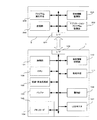
デジタルカメラ1は通常の記録再生機能として以下の機能を備えている。即ち被写体を撮影する撮像部101、撮影画像をデジタル化し記録再生処理をする記録再生処理部102、この記録再生処理部102ではガンマ補正、ホワイトバランス調整、圧縮・伸長等通常の記録再生に必要な処理を行う。この信号を処理する途中等で画像データを一時的に保持しておくバッファ103、フラッシュメモリ等で構成されたメモリカード104、カード装着部105、撮影条件の設定、再生画像の選択などやメニュー表示に従って種々の設定をする操作釦106、撮影画像や再生画像を表示する表示手段(LCDモニタ)107、これらの動作を制御するCPU108を備えている。ここまで説明した各ブロックは通常のデジタルカメラを構成するのに必要な機能の一部であって、そのほかにもデジタルカメラとして必要な構成要素はあるが、本発明の説明に不要なブロックは省略している。
【0011】
更に本発明を実現するのに必要なブロックを説明する。デジタルカメラ1には携帯電話やゲーム機等の周辺機器2とのデータのやり取りをするインタフェース部109、周辺機器2で動作させるアプリケーションプログラムに関連した特有情報を記憶する特有情報記憶部110、前記特有情報に基づいて所定の処理を行う処理手段111が備わっている。これらインタフェース部109〜処理手段111もCPU106によって制御される。
【0012】
デジタルカメラに接続されデータの授受を行う周辺機器2はインタフェース部201、ゲームソフト等の各種アプリケーションソフトプログラムを記憶しておくアプリケーションプログラム記憶部202、アプリケーションプログラムに関連した特有情報を記憶しておく特有情報記憶部203、アプリケーションプログラムを実行させるプログラム実行手段204、アプリケーションプログラムで使用するデジタルカメラ1から入力した画像データを記憶しておく記憶部205を備えている。ここで、特有情報とは前述したアプリケーションプログラムで使用するキャラクタのサイズ、表示色数、解像度、撮影方向や撮影画面内の被写体の大きさや被写体撮影範囲等の情報をデジタルカメラに伝えるとともにこれらの情報に基づいて画像データを加工処理させるためのアプレットプログラムである。アプリケーションプログラムとは例えば携帯電話やテレビ電話での待ち受け画面やゲーム機、パーソナルコンピュータで使用するゲームソフト等を指す。この周辺機器2においても本発明に関連のない機能や操作部材については省略している。
【0013】
図2にデジタルカメラ1とそれに接続される周辺機器の代表的なものを示す。図2においてカード装着部105、操作釦106、LCDモニタ107、インタフェース部109等で構成されているデジタルカメラ1は接続ケーブル20を介して携帯電話21、パーソナルコンピュータ22、ゲーム機23、テレビ電話24等と接続される。デジタルカメラからはそれぞれの周辺機器で動作しているアプリケーションプログラム上で使用される画像データが転送される。 ここで、図2ではUSB(Universal Serial Bus)等を用いた接続ケーブル20を介した接続の例が示されているがIrDA(Infrared Data Association)等の無線接続する方法であっても良い。
【0014】
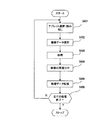
図3は図1のブロック図で表されるデジタルカメラの動作を示すフローチャートである。図3においてまずステップS101でデジタルカメラ1は周辺機器2が接続されたことを検出する。ステップS102ではアプリケーションプログラムが周辺機器2で起動したことを検出し、ステップS103においてそのプログラムに関連したアプレットプログラムを周辺機器2から読み込む。なお、周辺機器2でアプリケーションが起動した後にデジタルカメラ1と周辺機器2とが接続されたならばその接続時にデジタルカメラ1は動作中のアプリケーションプログラムに関連したアプレットプログラムを読み込む。
【0015】
ステップS104では周辺機器2に出力する画像ファイルを選択する。ここではアプレットプログラムに適合した撮影方向、上半身或いは全身像等の画像データをメモリカード104から選択したり撮影部101で被写体をアプレットプログラムの指示に基づいて撮影する。この選択した画像ファイルに対してステップS105でアプレットプログラムに基づいて所定の画素数、解像度、表示色数となるよう処理をした後にステップS106でインタフェース部107を介して処理済み画像データとして周辺機器2に出力する。
【0016】
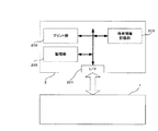
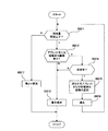
図4では図2に更に周辺機器2としてプリンタが接続された場合について説明する。周辺機器2には画像データをプリントするプリント部205が備わっている。ここでは前述したアプリケーションプログラムとしてはプリンタを動作させプリント出力をさせるプログラムを指す。また、特有情報記憶部にはこのプリント部のプリント特性を補正するカラーマッチング情報やプリンタの最大解像度情報も含まれる。図4の動作を図5のフローチャートに基づいて説明する。まず図5のステップS201においてデジタルカメラ1に周辺機器2としてプリンタが接続されているかどうか判定する。もし接続されていなかったならばステップS202において撮影画像に対して通常の記録処理をする。すなわち、撮像部101で被写体を撮影したのち通常のガンマ調整やホワイトバランス等の処理を施した後必要に応じて圧縮してステップS203でメモリカード104に記録する。
【0017】
ステップS201でプリンタが接続されていたならばステップS204でプリンタから特有情報であるアプレットプログラムを読み込む。ステップS205では読み込んだアプレットプログラムに基づいて所定の方向や大きさで被写体を撮影する。ステップS206では撮影画像をメモリカードに記録するかどうか判定する。もし操作釦106で撮影画像を記録しないように設定していたならばステップS207で先程読み込んだアプレットプログラムに基づいてカラーマッチング処理等を施してステップS208でプリンタに処理済み画像を出力する。もしステップS206でメモリカードに記録するよう設定してあったとしたならばステップS207で処理をすると共に元の通常の記録処理を施してある撮影画像をステップS203でメモリカードに記録する。その際メモリカードが一杯になったならば古い画像データから順に上書きする。
【0018】
撮影画像を残しておくという点ではステップS206でメモリカードへの記録設定をしておいた方が望ましいが、例えばカメラとプリンタを街頭に設置して不特定多数の被写体を大量に撮影しプリントするような業務用途等においてはいちいち撮影画像を残しておく必要はない。そのような場合にはメモリカードに記録しないよう設定しておく方が適している。
【0019】
図6には図4で説明したデジタルカメラとプリンタが一体となって構成された場合を示している。この場合には図1や図4における特有情報記憶部110、203はいずれか一方のみが備わっていれば良い。またインタフェース部109、201は適宜の内部通信手段があればよい。これらのことは、プリンタ一体型デジタルカメラに限らず、画像取り込み部を備えたゲーム機やパーソナルコンピュータ等、デジタルカメラと周辺機器とが一体化されている構成の場合であっても同様である。
【0020】
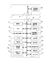
図7は本発明による第2の実施例のブロック図である。図中、デジタルカメラ3は図1と同様に撮像部101、記録・再生部102、バッファ103、操作釦106、表示手段107、CPU108、インタフェース部109を備えている。更に、デジタルカメラ3に接続可能な複数種類の周辺機器4に対応した特有情報を含むアプレットプログラムが特有情報記憶部301に記憶されている。ここで周辺機器とはプリンタ、モニタ、携帯電話等を指し、更には同一種類の機器の中でも例えば機種が異なっているような場合もこれに相当する。
【0021】
特有情報とはこれら各周辺機器で表示したりプリントする際の画素数、最大の解像度、表示色数、カラーマッチング情報、プリンタの最大解像度情報、モニタのガンマ特性等の情報をデジタルカメラ3に伝えるとともにこれらの情報に基づいて画像データを加工処理させるためのアプレットプログラムである。操作釦106は画像データ記憶部304の中から画像を選択したり特有情報記憶部301の中から必要なアプレットプログラムを選択する。なおアプレットプログラムは、後述する周辺機器識別手段305の識別結果に基づいて特有情報記録部301から特有情報選択手段302によっても選択される。
【0022】
処理手段303は選択されたアプレットプログラムに基づいてこれら選択された画像に対して所定の処理を施す。処理後の画像データは画像データ記憶部304に記憶する。この時管理手段310により選択画像と処理後の画像は関連付けて管理される。周辺機器識別手段305はデジタルカメラ3に周辺機器が接続された時にその周辺機器のメーカー名、製品名、製品番号等を識別するとともにその周辺機器に対応したアプレットプログラム名を識別する。この識別結果に基づいて特有情報選択手段302は同一のアプレットプログラムを特有情報記憶部301から選択する。
【0023】
もし、同一のアプレットプログラムが記憶されていなかった場合や古いアプレットプログラムが記憶されていた場合には周辺機器4から新しいアプレットプログラムを入手して特有情報記憶部301に記憶する。複数の周辺機器が同時にデジタルカメラ3に接続された場合にはこの周辺機器識別手段305の識別結果に基づいて各周辺機器毎に最適の処理済み画像データを出力する。
【0024】
特有情報記憶部301と画像データ記憶部304とは共通のデータ記憶エリア306内にあって、特有情報と画像データはCPU108によってそれぞれの記録エリアが指定される。この共通のデータ記憶エリアとは例えばメモリカード内の画像や音声データの記録エリアを指す。また、この画像データ記憶部304には記録・再生手段102により通常の記録処理を行った画像データと処理手段303によって特有情報に応じて処理された画像データの両方が記憶される。この共通の記録エリアの残容量は表示手段であるLCDモニタ107に表示される。
【0025】
周辺機器識別手段305によって識別されたアプレットプログラム名と特有情報選択手段302によって選択されたアプレットプログラムは比較手段307によって両者が一致しているかどうか比較される。一致していない場合には音声警告手段308で警告する。消去手段309はデータ記憶エリア306内の不要データを消去する。周辺機器4はインタフェース部401、この周辺機器に関連した特有情報を含むアプレットプログラムを記憶しておく特有情報記憶部402を備えている。
【0026】
図8〜図14は図7に示したデジタルカメラの動作の一例を示したフローチャートおよびモニタ表示の一例である。まず図8のステップS401で操作釦106を操作してメモリカード内の特有情報記憶部301に記憶されているアプレットプログラム名をLCDモニタ107に表示し、そこから希望するアプレットプログラムを選択する。ステップS402でも同様にして今度はメモリカード内の画像データ記憶部304から画像を読み出しLCDモニタ107表示してデジタルカメラ3から出力したい画像を選択する。その後ステップS403では選択したアプレットプログラムを基に出力機器に適合するよう所定の処理を施す。
【0027】
ステップ404ではCPU108の指示により管理手段310で前述した選択画像と処理後の画像の関連づけを行い、ステップS405で処理済みのデータをバッファ103あるいはメモリカード内の画像データ記憶部304に記憶する。もし複数種類の周辺機器に同時に出力したい場合には、複数の周辺機器に対応したアプレットプログラムを複数選択しこれらのアプレットプログラムによって処理された画像を画像データ記憶部304に記憶すると共に選択画像と複数の周辺機器に対応した処理済み画像データを関連付けておく。
【0028】
この関連付けについて図9を基に説明する。図9はLCDモニタ107における画像再生の一例で、ここでは画面の四分の一の大きさで画像内容とその画像ファイル名が同時に表示されている。ここから操作釦106を操作して画像を選択すると画像データ記憶部に記憶されている通常記憶用に処理された画像データに対して、図8ステップS401で予め選択しておいた特有情報に応じた処理が施される。この様にしてLCDモニタ107に表示された画像或いは画像ファイル名と処理済み画像との間を管理手段310は関連付ける。表示されている画像あるいは画像ファイル名と画像データ部の処理前の画像ももちろん関連づけられている。もしも複数の出力機器に対応した処理済み画像がある場合には更に処理済み画像間の関連付けも行う。こうすることにより例えば、デジタルカメラにプリンタと外部モニタとを同時に接続し、この外部モニタに表示されている画像あるいは画像ファイル名を選択した場合にもプリンタからプリンタに関連付けて管理されている処理済み画像データに基づいたプリントを出力することが出来る。
【0029】
このようにして関連付けられた処理済み画像データはCPU108によりバッファ103あるいはメモリカード内の画像データ記憶部304に記憶される。ステップS406では処理したい画像データの全てについて終了したかどうか判別し、終了していなかったらステップS401に戻りこれまでの処理を繰り返す。特有情報が複数選択された場合も同様にこの処理を繰り返す。この様にしてデジタルカメラ3内には複数の特有情報に対応して処理された複数の画像データが所定の関連付けをされた後に記憶される。この関連付けするタイミングはここで述べた例に限らず、任意の時点で処理済み画像に対して関連付けしたり逆に関連を解除したりすることは管理手段310で容易に行うことが出来る。
【0030】
図10はデジタルカメラ3で予め図8の手順に基づいて処理された複数の画像データがバッファ103あるいはメモリカード内の画像データ記憶部304に記憶された後に周辺機器が接続された場合のフローを示している。図10において、デジタルカメラの電源を入れるとステップS501でメモリカード内の残コマ数がLCDモニタ107に表示される。図11に残コマ表示の一例を示す。図11において100コマという数字はメモリカード内のアプレットプログラムあるいは処理済み画像データが記憶されているエリアを除いた残りの記録可能コマ数で、( )内の105という数字はデータ記憶エリアに現在記憶されているアプレットプログラムあるいは処理済み画像データを全て消去した場合の残りの記憶可能コマ数を表している。
【0031】
この残コマ表示のステップS501の詳細について図12と図13を使用してまず始めに説明する。図12においてステップS5011で残コマ数が少なくなって例えば10コマとなったならばステップS5012に進み、メモリカード内にアプレットプログラムあるいは処理済み画像が記録されているかどうかLCDモニタ107に表示する。もしアプレットプログラムあるいは処理済み画像が何も記録されていなかった場合には通常画像のみが記録されているので次のステップS5013でLCD107に残コマが少ないという警告表示(不図示)をして終了する。
【0032】
もしいくつかのアプレットプログラムあるいは処理済み画像が記憶されていたならば次のステップS5014でこれらを消去しても良いかどうかを図13に示すごとくLCDモニタ107に表示する。消去不可の場合はステップS5013に進み先程と同様に残コマが少ないという警告表示をして終了する。消去しても良いデータがある場合にはステップS5015に進み操作釦106を使って消去データを選択する。図13の表示例では特有情報記憶部301には現在4種類のアプレットプログラムが記憶されていて、画像データ記憶部にはこれら4種類のアプレットプログラムの中で2種類のアプレットプログラムを使った処理済み画像が記憶されていることを示している。さらにここでは図13に示すように3種類のアプレットプログラムを消去する為チェックしている。
【0033】
このあとYESを選択するとステップS5016でこれら選択されたデータが消去されステップS5011に戻る。ステップS5011で残容量が充分であるときにはステップS5017で図11に示した表示をする。また、図13ではアプレットと処理済み画像データを一体として消去するよう扱ったがアプレットと処理済み画像データを別々に選択できるようにしても良い。更に処理済み画像データも1画面ずつ選択できるようにしても良い。
【0034】
この様にして残コマ表示と残コマ処理が終了すると次に図10のステップS502で周辺機器識別手段305により接続された周辺機器の種類を識別する。ステップS503では特有情報選択手段302によって周辺機器識別手段305の識別結果に基づいて所定のアプレットプログラムが選択されLCDモニタ107にこれを表示する。
【0035】
図14にモニタ表示の一例を示す。図14の例では、周辺機器識別手段305はデジタルカメラ3に接続された機器をA社製プリンタで、型名はXYZ、そしてこのプリンタに記憶されているアプレットのバージョンがVer.3.0であると識別したことを示している。一方、特有情報選択手段302はこの識別された機器に最も近いアプレットプログラムとして特有情報記憶部301からA社プリンタ、型名XYZ、Ver.2.0というアプレットプログラムを選択したことを示している。この場合、A社製のプリンタで型名までは一致しているがバージョンが古いものが記憶されている。この様な場合にブザー等の音声警告手段308で注意を促すと効果的である。
【0036】
次にステップS504でこの選択が正しいかどうかユーザが判定する。ここでもしバージョンが違っていても問題ないと判断しYESを選択するとステップS505で処理済みの画像データを選択し、ステップS506でインタフェース109から出力する。もし処理済み画像がなかったならば図8に示したステップで処理済み画像を作成する。
【0037】
図14でNOを選択するとステップS507に進み、そこでは図15に示すように他の処理アプレットを選択させるための表示がされる。図15の表示例においては3通りの選択肢が示されている。第1番目は接続周辺機器から新たにアプレットプログラムを読み込む方法、2番目はデジタルカメラ3に予め記憶されている所定のアプレットプログラムで処理する方法、3番目はデジタルカメラ3に現在記憶されている他のアプレットプログラムから選択して処理する方法である。これらから適宜選択して実行しステップS504に戻る。この場合においても処理済み画像がなかったならば図8に説明した手順で処理済み画像を作成する。
【0038】
ここまではLCDモニタ107の表示結果に基づいてユーザが適宜の方法で処理済みの画像データを出力する方法について説明してきたが、この表示をもとにユーザが選択することと同様のことを比較手段307に自動的に行わせるように設定しても良い。アプレットプログラムを選択して以降の手順は前述したユーザが表示を見ながら処置を決定する場合と同様であるので説明は省略する。その際、比較結果が一致していなかった場合の処置については操作釦106を使用して予め設定しておく。
【0039】
図16は本発明による第3の実施例の場合のデジタルカメラと周辺機器との接続を示す概略図である。図中、デジタルカメラ3は図7に示すブロック図と同様であるが、前述した画像データ記憶部304には画像データと音声データが記憶されている。
【0040】
図16においてデジタルカメラ3はLCDモニタ107、音声警告手段であるブザー308、シャッタ釦111、各種選択をする操作釦106、インタフェース部109等で構成されている。インタフェース部109からは接続ケーブル20を介して音声と画像データを再生するテレビモニタ25、音声専用再生機26、プリンタ27に接続される。
【0041】
ここで、接続方法は前述したように有線・無線方式の何れであっても良い。図17のフローチャートを基に本実施例の動作を説明する。まずデジタルカメラ3と周辺機器とが接続されるとステップS601において周辺機器識別手段305によって周辺機器が識別され、それに基づいてCPU106が出力形態を3通りに選択する。出力形態1とはステップS602に示すように画像・音声両方選択する場合であってテレビモニタ25が接続された場合に相当する。出力形態2とはステップS602に示す画像ファイルを選択する場合でプリンタ27が接続された場合である。出力形態3とはステップS604に示す音声ファイルを選択する場合であってラジオ等の音声専用再生機26が接続された場合である。
【0042】
ステップS605ではこれらのデータ選択後出力が終了するまで図18に示すように出力データの形態をLCDモニタ107に表示する。図18では画像と音声の両方が選択されたあるいは出力されている場合を示している。バッテリの消耗を軽減するために所定時間後にLCDモニタ107をオフするようにしても良い。この実施例における周辺機器への出力データもこれまで説明してきたのと同様、アプレットプログラムに対応した処理を受けている。
【0043】
【発明の効果】
以上説明したように、本発明では、ゲーム等のアプリケーションソフトで使用するキャラクタを、アプリケーションソフトからの情報に基づいてユーザの好みに応じて変更することが出来るようにしたので、ユーザはアプリケーションソフトを常に新鮮に楽しくプレイすることが出来る。またその際、接続された周辺機器の種類及びその周辺機器に対応した特有情報を識別し、この識別した結果に基づいてデジタルカメラに記憶されている特有情報の中から識別した特有情報に最も近い特有情報を選択し、この識別結果と選択結果とを比較した結果に応じて最終的な特有情報選択を行っているので間違った処理を施したデータを出力することが防止される。
【図面の簡単な説明】
【図1】本発明によるデジタルカメラシステムのブロック図である。
【図2】デジタルカメラに接続される周辺機器の説明図である。
【図3】本発明によるデジタルカメラの動作を説明するフローチャートである。
【図4】周辺機器がプリンタの場合のデジタルカメラシステムのブロック図である。
【図5】図4のデジタルカメラの動作を説明するフローチャートである。
【図6】プリント部一体型デジタルカメラのブロック図である。
【図7】本発明によるデジタルカメラシステムの第2の実施例を示すブロック図である。
【図8】図7のデジタルカメラの動作を説明するフローチャートである。
【図9】モニタ上での画像再生の一例を示す図である。
【図10】図7のデジタルカメラの動作を説明するフローチャートである。
【図11】モニタ上での残コマ表示の一例を示す図である。
【図12】図7のデジタルカメラの動作を説明するフローチャートである。
【図13】特有情報を消去する際のモニタ表示の一例を示す図である。
【図14】接続周辺機器を判定する際のモニタ表示の一例を示す図である。
【図15】特有情報を選択する際のモニタ表示の一例を示す図である。
【図16】第3の実施例のデジタルカメラに接続される周辺機器の説明図である。
【図17】図16のデジタルカメラの動作を説明するフローチャートである。
【図18】図16のデジタルカメラの動作時のモニタ表示の一例を示す図である。
【符号の説明】
1 デジタルカメラ
2 周辺機器
3 デジタルカメラ
4 周辺機器
20 接続ケーブル
21 携帯電話
22 パーソナルコンピュータ
23 ゲーム機器
24 テレビ電話
25 画像・音声再生機
26 音声再生機
27 プリンタ
101 撮像部
102 記録・再生処理部
103 バッファ
104 メモリカード
105 カード装着部
106 操作釦
107 LCDモニタ
108 CPU
109 インタフェース
110 特有情報記憶部
111 処理手段
112 プリント部
201 インタフェース
202 アプリケーションプログラム記憶部
203 特有情報記憶部
204 プログラム実行手段
205 記憶部
206 プリント部
301 特有情報記憶部
302 特有情報選択手段
303 処理手段
304 画像データ記憶部
305 周辺機器識別手段
306 データ記憶エリア
307 比較手段
308 音声警告手段
309 消去手段
310 管理手段
401 インタフェース
402 特有情報記憶手段[0001]
BACKGROUND OF THE INVENTION
The present invention relates to a digital camera system that exchanges data between a digital camera and its peripheral devices.
[0002]
[Prior art]
Conventionally, there is a demand to use an image photographed with a digital camera for a game character or a standby screen of a mobile phone, and a game or a mobile phone capable of capturing an image actually photographed with a camera as a character is also known. This prevents the user from getting tired of watching the screen in a game repeated multiple times. Similarly, in the mobile phone, the standby screen can be appropriately changed according to the user's preference. The LCD monitor for display in this cellular phone has a size of about 2 inches, the number of dots is tens of thousands of dots, and the display color is about tens of thousands of colors, which is very small compared to the number of pixels and display colors on the camera side. In fact, a digital camera that outputs a pixel number of 320 × 240 pixels is also known for such a standby screen.
[0003]
[Problems to be solved by the invention]
The number of output pixels for the standby screen of the digital camera described above is preset on the camera side, and the number of pixels cannot be selected according to the mobile phone. Of course, it is also impossible to select the number of output pixels corresponding to the type of game. In some cases, it may be uneconomical to send hundreds of times more image data than necessary.
[0004]
In this way, an object of the present invention is to provide a digital camera system capable of transmitting information necessary for a program used in a peripheral device connected to the digital camera.
[0005]
[Means for solving problems]
In order to solve the above problems, the invention of
An application program storage unit for storing one or a plurality of application programs, a unique information storage unit for storing the specific information related to one or a plurality of application programs stored in the application program storage unit, and the specific information Specific information output unit that outputs the processed image data to the digital camera, an image data input unit that inputs the processed image data from the digital camera, a storage unit that stores the processed image data, and a storage unit that stores the processed image data A digital camera system comprising: a peripheral device including execution means that takes in the processed image data that has been processed into the application program and executes the application program. That is, in a game application program to be played on a game machine, a personal computer, or the like, character information used therein is output from the game machine to the digital camera. In response to this, the digital camera creates image data that has undergone predetermined processing in accordance with the character information and sends it back to the game machine. This allows the user to enjoy the game with a new character.
[0006]
According to a second aspect of the present invention, the image processing system includes the imaging unit and an application program processing unit, and the application processing unit includes the specific information storage unit, the execution unit, and the display unit. It is said.
[0008]
The invention of claim 5 is characterized in that the image data is a game character. The invention of claim 6 is characterized in that the application program is a standby screen used in a mobile phone.
[0009]
DETAILED DESCRIPTION OF THE INVENTION
Embodiments of the present invention will be described below with reference to the drawings.
FIG. 1 is a block diagram of a digital camera system according to the first embodiment of the present invention.
[0010]
The
[0011]
Further, blocks necessary for realizing the present invention will be described. The
[0012]
The
[0013]
FIG. 2 shows a typical
[0014]
FIG. 3 is a flowchart showing the operation of the digital camera represented by the block diagram of FIG. In FIG. 3, first, in step S101, the
[0015]
In step S104, an image file to be output to the
[0016]
FIG. 4 illustrates a case where a printer is further connected as the
[0017]
If the printer is connected in step S201, an applet program which is unique information is read from the printer in step S204. In step S205, the subject is photographed in a predetermined direction and size based on the read applet program. In step S206, it is determined whether or not the captured image is recorded on the memory card. If the
[0018]
It is desirable to set recording on the memory card in step S206 from the standpoint of leaving the photographed image. For example, a camera and a printer are installed on the street, and a large number of unspecified subjects are photographed and printed. For such business use, there is no need to leave a photographed image. In such a case, it is more appropriate to set not to record in the memory card.
[0019]
FIG. 6 shows a case where the digital camera and printer described in FIG. 4 are integrated. In this case, only one of the unique
[0020]
FIG. 7 is a block diagram of a second embodiment according to the present invention. As shown in FIG. 1, the
[0021]
The specific information is transmitted to the
[0022]
The processing means 303 performs a predetermined process on these selected images based on the selected applet program. The processed image data is stored in the image
[0023]
If the same applet program is not stored or if an old applet program is stored, a new applet program is obtained from the
[0024]
The unique
[0025]
The applet program name identified by the peripheral device identifying means 305 and the applet program selected by the specific
[0026]
8 to 14 are a flowchart showing an example of the operation of the digital camera shown in FIG. 7 and an example of a monitor display. First, in step S401 in FIG. 8, the
[0027]
In
[0028]
This association will be described with reference to FIG. FIG. 9 shows an example of image reproduction on the
[0029]
The processed image data associated in this way is stored by the
[0030]
FIG. 10 shows a flow when a peripheral device is connected after a plurality of pieces of image data processed in advance by the
[0031]
Details of the remaining frame display step S501 will be described first with reference to FIGS. In FIG. 12, when the number of remaining frames is reduced to 10 frames in step S5011, for example, the process proceeds to step S5012 to display on the
[0032]
If several applet programs or processed images are stored, whether or not they can be deleted is displayed on the
[0033]
Thereafter, when YES is selected, the selected data is deleted in step S5016, and the process returns to step S5011. If the remaining capacity is sufficient in step S5011, the display shown in FIG. 11 is displayed in step S5017. In FIG. 13, the applet and the processed image data are dealt with as an integral deletion, but the applet and the processed image data may be selected separately. Further, processed image data may be selected on a screen-by-screen basis.
[0034]
When the remaining frame display and the remaining frame processing are completed in this way, the peripheral device type connected by the peripheral device identifying means 305 is identified in step S502 of FIG. In step S503, a specific applet program is selected by the specific
[0035]
FIG. 14 shows an example of the monitor display. In the example of FIG. 14, the peripheral
[0036]
In step S504, the user determines whether this selection is correct. If it is determined that there is no problem even if the versions are different and YES is selected, the processed image data is selected in step S505, and is output from the
[0037]
If NO is selected in FIG. 14, the process proceeds to step S507, where a display for selecting another processing applet is displayed as shown in FIG. In the display example of FIG. 15, three options are shown. The first is a method of reading a new applet program from a connected peripheral device, the second is a method of processing with a predetermined applet program stored in advance in the
[0038]
Up to this point, the method of outputting image data that has been processed by the user according to an appropriate method based on the display result of the
[0039]
FIG. 16 is a schematic diagram showing the connection between a digital camera and peripheral devices in the third embodiment according to the present invention. In the figure, the
[0040]
In FIG. 16, the
[0041]
Here, the connection method may be either wired or wireless as described above. The operation of this embodiment will be described based on the flowchart of FIG. First, when the
[0042]
In step S605, the output data form is displayed on the
[0043]
【The invention's effect】
As described above, in the present invention, the character used in application software such as a game can be changed according to the user's preference based on information from the application software. You can always play fresh and fun. At that time, the type of the connected peripheral device and the specific information corresponding to the peripheral device are identified, and based on the identified result, the specific information identified from the specific information stored in the digital camera is closest. Since the specific information is selected and the final specific information is selected according to the comparison result between the identification result and the selection result, it is possible to prevent the output of the data subjected to the wrong processing.
[Brief description of the drawings]
FIG. 1 is a block diagram of a digital camera system according to the present invention.
FIG. 2 is an explanatory diagram of peripheral devices connected to the digital camera.
FIG. 3 is a flowchart illustrating the operation of the digital camera according to the present invention.
FIG. 4 is a block diagram of a digital camera system when the peripheral device is a printer.
5 is a flowchart for explaining the operation of the digital camera of FIG. 4;
FIG. 6 is a block diagram of a print unit integrated digital camera.
FIG. 7 is a block diagram showing a second embodiment of the digital camera system according to the present invention.
8 is a flowchart for explaining the operation of the digital camera of FIG.
FIG. 9 is a diagram illustrating an example of image reproduction on a monitor.
10 is a flowchart for explaining the operation of the digital camera of FIG.
FIG. 11 is a diagram illustrating an example of a remaining frame display on a monitor.
12 is a flowchart for explaining the operation of the digital camera of FIG.
FIG. 13 is a diagram showing an example of a monitor display when deleting specific information.
FIG. 14 is a diagram illustrating an example of a monitor display when determining a connected peripheral device.
FIG. 15 is a diagram illustrating an example of a monitor display when selecting specific information.
FIG. 16 is an explanatory diagram of peripheral devices connected to the digital camera of the third embodiment.
17 is a flowchart for explaining the operation of the digital camera of FIG.
18 is a diagram illustrating an example of a monitor display during operation of the digital camera of FIG.
[Explanation of symbols]
1 Digital camera
2 Peripheral devices
3 Digital camera
4 Peripheral devices
20 Connection cable
21 Mobile phone
22 Personal computer
23 Game equipment
24 Videophone
25 Image / sound player
26 Audio player
27 Printer
101 Imaging unit
102 Recording / playback processing unit
103 buffers
104 memory card
105 Card slot
106 Operation buttons
107 LCD monitor
108 CPU
109 interface
110 Specific information storage unit
111 Processing means
112 Print section
201 interface
202 Application program storage unit
203 Specific information storage unit
204 Program execution means
205 storage unit
206 Print section
301 Specific information storage unit
302 Specific information selection means
303 Processing means
304 Image data storage unit
305 Peripheral device identification means
306 Data storage area
307 comparison means
308 Voice alert means
309 Erasing means
310 Management means
401 interface
402 Specific information storage means
Claims (6)
一つあるいは複数のアプリケーションプログラムを記憶するアプリケーションプログラム記憶部と、前記アプリケーションプログラム記憶部に記憶された一つあるいは複数のアプリケーションプログラムに関連した前記特有情報を記憶する特有情報記憶部と、前記特有情報を前記デジタルカメラに出力する特有情報出力部と、前記デジタルカメラから前記処理をした画像データを入力する画像データ入力部と、前記処理をした画像データを記憶する記憶部と、前記記憶部に記憶されている前記処理をした画像データを前記アプリケーションプログラムに取り込んで前記アプリケーションプログラムを実行する実行手段とを備えた周辺機器と、から成るデジタルカメラシステム。A specific information input unit for inputting specific information for processing image data from the peripheral device into characteristics suitable for output by the peripheral device, a specific information storage means for storing the specific information, the peripheral device and the data Based on data input from the data input / output unit according to the connection of the peripheral device, the type of the peripheral device and the specific information stored in the peripheral device Identification means for identifying, and unique information selection means for selecting predetermined specific information from among a plurality of unique information stored in the unique information storage means based on the type of the peripheral device identified by the identification means Whether or not the specific information stored in the peripheral device identified by the identification means matches the predetermined specific information selected by the specific information selection means Comparing means for comparing, processing means for processing image data based on a comparison result by the comparing means, and image data for outputting the image data processed by the processing means to the peripheral device A digital camera with an output unit;
An application program storage unit that stores one or a plurality of application programs, a unique information storage unit that stores the specific information related to one or a plurality of application programs stored in the application program storage unit, and the specific information Specific information output unit that outputs the processed image data to the digital camera, an image data input unit that inputs the processed image data from the digital camera, a storage unit that stores the processed image data, and a storage unit that stores the processed image data A digital camera system comprising: a peripheral device provided with execution means for fetching the processed image data that has been processed into the application program and executing the application program.
Priority Applications (5)
| Application Number | Priority Date | Filing Date | Title |
|---|---|---|---|
| JP2002188834A JP4135412B2 (en) | 2002-06-28 | 2002-06-28 | Image information processing system |
| US10/456,782 US20040001156A1 (en) | 2002-06-28 | 2003-06-09 | Digital camera system |
| EP03253976.9A EP1377019B1 (en) | 2002-06-28 | 2003-06-24 | Digital camera system |
| EP17199183.9A EP3306905A1 (en) | 2002-06-28 | 2003-06-24 | Digital camera system |
| US10/879,180 US7999854B2 (en) | 2002-06-28 | 2004-06-30 | Digital camera for outputting image data according to application program, and peripheral for carrying out application program |
Applications Claiming Priority (1)
| Application Number | Priority Date | Filing Date | Title |
|---|---|---|---|
| JP2002188834A JP4135412B2 (en) | 2002-06-28 | 2002-06-28 | Image information processing system |
Publications (3)
| Publication Number | Publication Date |
|---|---|
| JP2004032564A JP2004032564A (en) | 2004-01-29 |
| JP2004032564A5 JP2004032564A5 (en) | 2005-10-27 |
| JP4135412B2 true JP4135412B2 (en) | 2008-08-20 |
Family
ID=29717661
Family Applications (1)
| Application Number | Title | Priority Date | Filing Date |
|---|---|---|---|
| JP2002188834A Expired - Fee Related JP4135412B2 (en) | 2002-06-28 | 2002-06-28 | Image information processing system |
Country Status (3)
| Country | Link |
|---|---|
| US (2) | US20040001156A1 (en) |
| EP (2) | EP3306905A1 (en) |
| JP (1) | JP4135412B2 (en) |
Families Citing this family (7)
| Publication number | Priority date | Publication date | Assignee | Title |
|---|---|---|---|---|
| JP2005268877A (en) * | 2004-03-16 | 2005-09-29 | Matsushita Electric Ind Co Ltd | Imaging apparatus and image data conversion method |
| FR2875924B1 (en) * | 2004-09-27 | 2007-03-02 | Georges Bacha | MULTISERVICE TERMINAL, TERMINAL AND METHOD OF CONTENT TRANSFER. |
| US20060173803A1 (en) * | 2005-01-28 | 2006-08-03 | Morris Robert P | Method and system for associating specific files with different applications |
| JP4779445B2 (en) * | 2005-05-26 | 2011-09-28 | 株式会社ニコン | Editing device, editing program and editing system |
| US7873746B2 (en) | 2007-07-27 | 2011-01-18 | Lagavulin Limited | User interface for a portable, image-processing transmitter |
| JP2009225401A (en) * | 2008-03-19 | 2009-10-01 | Casio Comput Co Ltd | Imaging apparatus, image processor and image processing method |
| US8780219B2 (en) | 2012-07-23 | 2014-07-15 | Wooblue, Inc. | Wireless viewing and control interface for imaging devices |
Family Cites Families (17)
| Publication number | Priority date | Publication date | Assignee | Title |
|---|---|---|---|---|
| US5402170A (en) * | 1991-12-11 | 1995-03-28 | Eastman Kodak Company | Hand-manipulated electronic camera tethered to a personal computer |
| US5595389A (en) * | 1993-12-30 | 1997-01-21 | Eastman Kodak Company | Method and apparatus for producing "personalized" video games using CD discs |
| JP3747108B2 (en) * | 1996-02-02 | 2006-02-22 | キヤノン株式会社 | Digital imaging apparatus and control method thereof |
| JPH11144040A (en) * | 1997-11-05 | 1999-05-28 | Nintendo Co Ltd | Portable game machine and cartridge for portable game machine |
| US6552743B1 (en) * | 1998-04-08 | 2003-04-22 | Hewlett Packard Development Company, L.P. | Digital camera-ready printer |
| JP2000047878A (en) * | 1998-07-31 | 2000-02-18 | Sony Computer Entertainment Inc | Data processing system, its method, data transmitting/ receiving device and its method |
| JP3788694B2 (en) * | 1998-09-16 | 2006-06-21 | 株式会社ソニー・コンピュータエンタテインメント | Data processing system and method, and entertainment apparatus |
| JP3398081B2 (en) * | 1999-03-01 | 2003-04-21 | 三洋電機株式会社 | Digital camera |
| JP3876573B2 (en) | 1999-09-20 | 2007-01-31 | カシオ計算機株式会社 | Net game apparatus and caricature image display control method |
| JP2001274936A (en) | 2000-01-21 | 2001-10-05 | Casio Comput Co Ltd | Image data transmission system and image pickup data transmission method |
| JP4552252B2 (en) | 2000-01-21 | 2010-09-29 | 株式会社セガ | Game device with voice and image input and communication functions |
| FR2805651B1 (en) * | 2000-02-24 | 2002-09-13 | Eastman Kodak Co | METHOD AND DEVICE FOR PRESENTING DIGITAL IMAGES ON A LOW DEFINITION SCREEN |
| US6811492B1 (en) * | 2000-03-20 | 2004-11-02 | Nintendo Co., Ltd. | Video game machine using digital camera and digital camera accessory for video game machine |
| JP2002153670A (en) * | 2000-11-17 | 2002-05-28 | Casio Comput Co Ltd | Electronic game system, electronic game apparatus and recording medium |
| JP3520860B2 (en) * | 2001-02-09 | 2004-04-19 | セイコーエプソン株式会社 | Image file output image adjustment |
| US20020196346A1 (en) * | 2001-03-15 | 2002-12-26 | Satoru Nishio | Image processing apparatus |
| US20030227554A1 (en) * | 2002-04-26 | 2003-12-11 | Nikon Corporation | Digital camera system |
-
2002
- 2002-06-28 JP JP2002188834A patent/JP4135412B2/en not_active Expired - Fee Related
-
2003
- 2003-06-09 US US10/456,782 patent/US20040001156A1/en not_active Abandoned
- 2003-06-24 EP EP17199183.9A patent/EP3306905A1/en not_active Withdrawn
- 2003-06-24 EP EP03253976.9A patent/EP1377019B1/en not_active Expired - Lifetime
-
2004
- 2004-06-30 US US10/879,180 patent/US7999854B2/en not_active Expired - Fee Related
Also Published As
| Publication number | Publication date |
|---|---|
| EP3306905A1 (en) | 2018-04-11 |
| US7999854B2 (en) | 2011-08-16 |
| EP1377019B1 (en) | 2017-11-01 |
| US20040239766A1 (en) | 2004-12-02 |
| EP1377019A2 (en) | 2004-01-02 |
| EP1377019A3 (en) | 2006-01-11 |
| US20040001156A1 (en) | 2004-01-01 |
| JP2004032564A (en) | 2004-01-29 |
Similar Documents
| Publication | Publication Date | Title |
|---|---|---|
| US20080278586A1 (en) | Digital camera system | |
| JP4357151B2 (en) | Digital camera and image data processing system | |
| JP4392548B2 (en) | Movie image printing apparatus, method and program | |
| JP4135412B2 (en) | Image information processing system | |
| JP2004007435A (en) | Electronic camera, image recording apparatus, image recording method, and program | |
| JP3909614B2 (en) | Information recording / reproducing apparatus and recording medium | |
| US20060050331A1 (en) | Display method during sensed image recording in image sensing apparatus | |
| JP4277486B2 (en) | Digital camera | |
| JP5990055B2 (en) | Imaging apparatus and control method thereof | |
| US7249898B2 (en) | Function control method for camera | |
| JP2004032567A (en) | Digital camera | |
| JP2004056641A (en) | Method, apparatus, and program for editing image file | |
| JP2004032562A (en) | Digital camera | |
| JP2004032563A (en) | Digital camera system and digital camera | |
| JP2004032565A (en) | Digital camera | |
| JP4720867B2 (en) | Image display system | |
| JP2003046841A (en) | Simple digital camera and image-ordering method using the same | |
| JP4185582B2 (en) | Imaging device, control device, signal processing system, method and recording medium | |
| US6151445A (en) | Film image input method and apparatus with image index data detection | |
| JP2003333519A (en) | Imaging apparatus and image data delivery method | |
| JP2004128900A (en) | Method for customizing operation menu, and electronic apparatus | |
| JP4239701B2 (en) | Electronic camera and program | |
| JPH08111730A (en) | Facsimile equipment | |
| JP4196710B2 (en) | Digital camera | |
| JP4349153B2 (en) | Imaging device, moving image display control method, and moving image display control program |
Legal Events
| Date | Code | Title | Description |
|---|---|---|---|
| A621 | Written request for application examination |
Free format text: JAPANESE INTERMEDIATE CODE: A621 Effective date: 20050624 |
|
| A521 | Request for written amendment filed |
Free format text: JAPANESE INTERMEDIATE CODE: A523 Effective date: 20050715 |
|
| A711 | Notification of change in applicant |
Free format text: JAPANESE INTERMEDIATE CODE: A711 Effective date: 20060412 |
|
| A977 | Report on retrieval |
Free format text: JAPANESE INTERMEDIATE CODE: A971007 Effective date: 20071221 |
|
| A131 | Notification of reasons for refusal |
Free format text: JAPANESE INTERMEDIATE CODE: A131 Effective date: 20080129 |
|
| A521 | Request for written amendment filed |
Free format text: JAPANESE INTERMEDIATE CODE: A523 Effective date: 20080331 |
|
| RD04 | Notification of resignation of power of attorney |
Free format text: JAPANESE INTERMEDIATE CODE: A7424 Effective date: 20080331 |
|
| TRDD | Decision of grant or rejection written | ||
| A01 | Written decision to grant a patent or to grant a registration (utility model) |
Free format text: JAPANESE INTERMEDIATE CODE: A01 Effective date: 20080513 |
|
| A01 | Written decision to grant a patent or to grant a registration (utility model) |
Free format text: JAPANESE INTERMEDIATE CODE: A01 |
|
| A61 | First payment of annual fees (during grant procedure) |
Free format text: JAPANESE INTERMEDIATE CODE: A61 Effective date: 20080526 |
|
| R150 | Certificate of patent or registration of utility model |
Ref document number: 4135412 Country of ref document: JP Free format text: JAPANESE INTERMEDIATE CODE: R150 Free format text: JAPANESE INTERMEDIATE CODE: R150 |
|
| FPAY | Renewal fee payment (event date is renewal date of database) |
Free format text: PAYMENT UNTIL: 20110613 Year of fee payment: 3 |
|
| FPAY | Renewal fee payment (event date is renewal date of database) |
Free format text: PAYMENT UNTIL: 20110613 Year of fee payment: 3 |
|
| FPAY | Renewal fee payment (event date is renewal date of database) |
Free format text: PAYMENT UNTIL: 20140613 Year of fee payment: 6 |
|
| S531 | Written request for registration of change of domicile |
Free format text: JAPANESE INTERMEDIATE CODE: R313531 |
|
| FPAY | Renewal fee payment (event date is renewal date of database) |
Free format text: PAYMENT UNTIL: 20140613 Year of fee payment: 6 |
|
| R350 | Written notification of registration of transfer |
Free format text: JAPANESE INTERMEDIATE CODE: R350 |
|
| FPAY | Renewal fee payment (event date is renewal date of database) |
Free format text: PAYMENT UNTIL: 20140613 Year of fee payment: 6 |
|
| R250 | Receipt of annual fees |
Free format text: JAPANESE INTERMEDIATE CODE: R250 |
|
| R250 | Receipt of annual fees |
Free format text: JAPANESE INTERMEDIATE CODE: R250 |
|
| R250 | Receipt of annual fees |
Free format text: JAPANESE INTERMEDIATE CODE: R250 |
|
| R250 | Receipt of annual fees |
Free format text: JAPANESE INTERMEDIATE CODE: R250 |
|
| R250 | Receipt of annual fees |
Free format text: JAPANESE INTERMEDIATE CODE: R250 |
|
| R250 | Receipt of annual fees |
Free format text: JAPANESE INTERMEDIATE CODE: R250 |
|
| R250 | Receipt of annual fees |
Free format text: JAPANESE INTERMEDIATE CODE: R250 |
|
| LAPS | Cancellation because of no payment of annual fees |