JP3788694B2 - Data processing system and method, and entertainment apparatus - Google Patents
Data processing system and method, and entertainment apparatus Download PDFInfo
- Publication number
- JP3788694B2 JP3788694B2 JP26201698A JP26201698A JP3788694B2 JP 3788694 B2 JP3788694 B2 JP 3788694B2 JP 26201698 A JP26201698 A JP 26201698A JP 26201698 A JP26201698 A JP 26201698A JP 3788694 B2 JP3788694 B2 JP 3788694B2
- Authority
- JP
- Japan
- Prior art keywords
- image data
- processing
- video game
- game machine
- data
- Prior art date
- Legal status (The legal status is an assumption and is not a legal conclusion. Google has not performed a legal analysis and makes no representation as to the accuracy of the status listed.)
- Expired - Fee Related
Links
Images


Classifications
-
- H—ELECTRICITY
- H04—ELECTRIC COMMUNICATION TECHNIQUE
- H04N—PICTORIAL COMMUNICATION, e.g. TELEVISION
- H04N1/00—Scanning, transmission or reproduction of documents or the like, e.g. facsimile transmission; Details thereof
- H04N1/00127—Connection or combination of a still picture apparatus with another apparatus, e.g. for storage, processing or transmission of still picture signals or of information associated with a still picture
- H04N1/00204—Connection or combination of a still picture apparatus with another apparatus, e.g. for storage, processing or transmission of still picture signals or of information associated with a still picture with a digital computer or a digital computer system, e.g. an internet server
-
- G—PHYSICS
- G06—COMPUTING OR CALCULATING; COUNTING
- G06F—ELECTRIC DIGITAL DATA PROCESSING
- G06F15/00—Digital computers in general; Data processing equipment in general
- G06F15/16—Combinations of two or more digital computers each having at least an arithmetic unit, a program unit and a register, e.g. for a simultaneous processing of several programs
-
- A—HUMAN NECESSITIES
- A63—SPORTS; GAMES; AMUSEMENTS
- A63F—CARD, BOARD, OR ROULETTE GAMES; INDOOR GAMES USING SMALL MOVING PLAYING BODIES; VIDEO GAMES; GAMES NOT OTHERWISE PROVIDED FOR
- A63F2300/00—Features of games using an electronically generated display having two or more dimensions, e.g. on a television screen, showing representations related to the game
- A63F2300/40—Features of games using an electronically generated display having two or more dimensions, e.g. on a television screen, showing representations related to the game characterised by details of platform network
- A63F2300/403—Connection between platform and handheld device
-
- H—ELECTRICITY
- H04—ELECTRIC COMMUNICATION TECHNIQUE
- H04N—PICTORIAL COMMUNICATION, e.g. TELEVISION
- H04N2201/00—Indexing scheme relating to scanning, transmission or reproduction of documents or the like, and to details thereof
- H04N2201/0008—Connection or combination of a still picture apparatus with another apparatus
- H04N2201/001—Sharing resources, e.g. processing power or memory, with a connected apparatus or enhancing the capability of the still picture apparatus
-
- H—ELECTRICITY
- H04—ELECTRIC COMMUNICATION TECHNIQUE
- H04N—PICTORIAL COMMUNICATION, e.g. TELEVISION
- H04N2201/00—Indexing scheme relating to scanning, transmission or reproduction of documents or the like, and to details thereof
- H04N2201/0008—Connection or combination of a still picture apparatus with another apparatus
- H04N2201/0034—Details of the connection, e.g. connector, interface
Landscapes
- Engineering & Computer Science (AREA)
- General Engineering & Computer Science (AREA)
- Computing Systems (AREA)
- Multimedia (AREA)
- Signal Processing (AREA)
- Computer Hardware Design (AREA)
- Theoretical Computer Science (AREA)
- General Physics & Mathematics (AREA)
- Physics & Mathematics (AREA)
- Software Systems (AREA)
- Studio Devices (AREA)
- Closed-Circuit Television Systems (AREA)
- Image Processing (AREA)
- Controls And Circuits For Display Device (AREA)
- Radar Systems Or Details Thereof (AREA)
- Stored Programmes (AREA)
- Signal Processing For Digital Recording And Reproducing (AREA)
- Traffic Control Systems (AREA)
- Editing Of Facsimile Originals (AREA)
Abstract
Description
【0001】
【発明の属する技術分野】
本発明は、外部機器とのデータ送受信を行うデータ処理システム及び方法、並びにエンタテインメント装置に関し、特に、ビデオゲーム機と携帯型情報通信端末とを用いたシステムに適用して好適なデータ処理システム及び方法、並びにエンタテインメント装置に関する。
【0002】
【従来の技術】
パーソナル・コンピュータ等の家庭用コンソールにおいては、例えば、デジタルカメラを接続することで、デジタルカメラで撮影した画像データを取り込んで使用することができる。また、パーソナル・コンピュータは、携帯型情報通信端末のような小型計算機を接続して、画像データをはじめとする各種データの送受信を行うことができる。
【0003】
一方、家庭用コンソールとしては、テレビゲーム装置のような従来のビデオゲーム機がある。この従来のビデオゲーム機は、例えば、記録メディアや補助記憶装置に記憶されたゲームデータ等を利用して、ビデオゲーム機本体上でアプリケーションプログラムを動作させ、一般にコントローラと称される操作装置等によって、例えば、対戦ゲーム等を行うものであり、広く世間に普及している。
【0004】
このビデオゲーム機においては、その使用者が、複雑かつリアルな画像や音声等を体験できるように、一般に、画像や音声データ等に対する優れた処理能力を有するものが多い。具体的に従来のビデオゲーム機においては、例えば、その優れたデータ処理能力を利用して、ゲームを行う上で必要となる複雑なゲームキャラクタの表示や、臨場感溢れる音声の表現等を可能とし、既存のコンピュータに比べ、繊細な画像や音声を提供することができる。
【0005】
【発明が解決しようとする課題】
ところで、従来のパーソナル・コンピュータ等の家庭用コンソールにおいて、デジタルカメラで撮影された画像データを取り込む際には、コンソールとデジタルカメラとの間のデータ転送しか考慮されておらず、1つの記録メディアに記録されているアプリケーションプログラムにより、携帯型情報通信端末のような小型計算機を含めた3者同時通信を行うシステムは確立されていなかった。
【0006】
また、デジタルカメラで撮影した画像データを小型計算機へ転送する際には、小型計算機で使用できる画像データに変換する必要が生じる。しかしながら、小型計算機とデジタルカメラとを直接接続すると、小型計算機の計算資源の限界から、効率のよいデータ転送を行うことは困難であった。
【0007】
一方、従来のビデオゲーム機は、上述したように、データに対する優れた処理能力を有しているが、アプリケーションプログラムを実行してゲームを行うための装置にとどまっている。そのため、小型計算機とデジタルカメラとを同時に接続して、画像データの送受信や画像データの加工処理を行うシステムは確立されておらず、ビデオゲーム機のリアルタイムグラフィック計算・表示機能を有効に用いたシステムが存在しなかった。
【0008】
さらに、小型計算機が画像データを使用して動作するアプリケーションプログラムを、小型計算機及びデジタルカメラの両者が接続される機器に装着される記録メディアで提供することはなかった。
【0009】
本発明は、上述した従来の問題点を鑑みてなされたものであって、親機に子機とデジタルカメラとを同時に接続して、直接接続することが困難である子機とデジタルカメラとの間で画像データの送受信を行うことができるデータ処理システム及び方法、並びにエンタテインメント装置を提供することを目的とする。
【0010】
【課題を解決するための手段】
この目的を達成する本発明にかかるデータ処理システムは、データ処理を行う親機と、この親機に着脱自在に接続される子機とを備えるデータ処理システムであって、親機は、外部に備えられる撮像装置が接続される第1の接続手段と、子機が接続される第2の接続手段と、第1の接続手段を介して撮像装置から多色かつ高解像度の撮像画像データを入力し、この撮像画像データに基づく少色かつ低解像度の処理画像データを、第2の接続手段を介して子機へと出力する際の制御を行う制御手段とを備えることを特徴としている。
【0011】
以上のように構成された本発明にかかるデータ処理システムにおいては、多色かつ高解像度の撮像画像データが、撮像装置から親機へと供給され、この撮像画像データに基づく少色かつ低解像度の処理画像データが、親機から子機へと供給される。
【0012】
また、本発明にかかるデータ処理システムは、データ処理を行う親機と、この親機に着脱自在に接続される子機とを備えるデータ処理システムであって、親機は、外部に備えられる撮像装置が接続される第1の接続手段と、子機が接続される第2の接続手段と、第2の接続手段を介して子機からの子機画像データを入力し、この子機画像データに基づく加工画像データを、第1の接続手段を介して撮像装置へと出力する際の制御を行う制御手段とを備えることを特徴としている。
【0013】
以上のように構成された本発明にかかるデータ処理システムにおいては、子機画像データが、子機から親機へと供給され、この子機画像データに基づく加工画像データが、親機から撮像装置へと供給される。
【0014】
さらに、本発明にかかるデータ処理システムは、親機が、着脱自在に装着される記録媒体からプログラムデータを読み出すデータ読出手段を備え、子機が、プログラムデータを実行する実行手段を備え、親機は、処理画像データを使用する子機用アプリケーションプログラムを、データ読出手段により記録媒体から読み出して、第2の接続手段を介して子機へと供給し、子機は、親機から供給された処理画像データを使用して、実行手段により子機用アプリケーションプログラムを実行することを特徴としている。
【0015】
以上のように構成された本発明にかかるデータ処理システムにおいては、子機で使用する子機用アプリケーションプログラムを、親機から供給して、子機に実行させる。
【0016】
本発明にかかるデータ処理方法は、データ処理を行う親機に、子機が着脱自在に接続されるデータ処理方法であって、親機は、外部に備えられる撮像装置から多色かつ高解像度の撮像画像データを入力し、この撮像画像データに基づく少色かつ低解像度の処理画像データを子機へと出力することを特徴としている。
【0017】
以上のような本発明にかかるデータ処理方法においては、多色かつ高解像度の撮像画像データが、撮像装置から親機へと供給され、この撮像画像データに基づく少色かつ低解像度の処理画像データが、親機から子機へと供給される。
【0018】
また、本発明にかかるデータ処理方法は、データ処理を行う親機に、子機が着脱自在に接続されるデータ処理方法であって、親機が、子機から子機画像データを入力し、この子機画像データに基づく加工画像データを外部に備えられる撮像装置へと出力することを特徴としている。
【0019】
以上のような本発明にかかるデータ処理方法においては、子機画像データが、子機から親機へと供給され、この子機画像データに基づく加工画像データが、親機から撮像装置へと供給される。
【0020】
さらに、本発明にかかるデータ処理方法は、親機が、処理画像データを使用する子機用アプリケーションプログラムを、着脱自在に装着される記録媒体から読み出して子機へと供給し、子機が、親機から供給された処理画像データを使用して、子機用アプリケーションプログラムを実行することを特徴としている。
【0021】
以上のような本発明にかかるデータ処理方法においては、子機で使用する子機用アプリケーションプログラムを、親機から供給して、子機がその子機用アプリケーションプログラムを実行する。
【0022】
本発明にかかるエンタテインメント装置は、子機を着脱自在に接続してデータ処理を行うエンタテインメント装置であって、外部に備えられる撮像装置が接続される第1の接続手段と、子機が接続される第2の接続手段と、第1の接続手段を介して撮像装置から多色かつ高解像度の撮像画像データを入力し、この撮像画像データに基づく少色かつ低解像度の処理画像データを、第2の接続手段を介して子機へと出力する際の制御を行う制御手段とを備えることを特徴としている。
【0023】
以上のように構成された本発明にかかるエンタテインメント装置においては、多色かつ高解像度の撮像画像データを、撮像装置から入力し、この撮像画像データに基づく少色かつ低解像度の処理画像データを、子機へと出力する。
【0024】
また、本発明にかかるエンタテインメント装置は、子機を着脱自在に接続してデータ処理を行うエンタテインメント装置であって、外部に備えられる撮像装置が接続される第1の接続手段と、子機が接続される第2の接続手段と、第2の接続手段を介して子機から子機画像データを入力し、この子機画像データに基づく加工画像データを、第1の接続手段を介して撮像装置へと出力する際の制御を行う制御手段とを備えることを特徴としている。
【0025】
以上のように構成された本発明にかかるエンタテインメント装置においては、子機画像データを、子機から入力し、この子機画像データに基づく加工画像データを、撮像装置へと出力する。
【0026】
さらに、本発明にかかるエンタテインメント装置は、着脱自在に装着される記録媒体からプログラムデータを読み出すデータ読出手段を備え、処理画像データを使用する子機用アプリケーションプログラムを、データ読出手段により記録媒体から読み出して、第2の接続手段を介して子機へと供給することを特徴としている。
【0027】
以上のように構成された本発明にかかるエンタテインメント装置においては、子機で使用する子機用アプリケーションプログラムを子機へと供給する。
【0028】
【発明の実施の形態】
以下、本発明を適用した具体的な実施の形態について図面を参照しながら詳細に説明する。
【0029】
この実施の形態は、図1に示すように、ビデオゲーム機2に対して、携帯型計算機(PDA)3が接続されるデータ処理システム1である。
【0030】
データ処理システム1は、図1に示すように、データ処理を行う親機であるビデオゲーム機2と、子機である携帯型計算機3とを備える。ビデオゲーム機2は、例えばCD−ROM等の図示しない記録メディアに記録されているプログラムデータを実行処理してビデオゲーム等を実行する、いわゆるエンタテインメント装置として構成されるものである。一方、携帯型計算機3は、ビデオゲーム機2に例えば着脱自在に接続してデータ送受信を行うことができるものであり、例えば無線通信機能を有する携帯型情報通信端末(PDA:Personal Digital Assistant)として構成されるものである。また、ビデオゲーム機2には、画像を撮影することができる撮像装置であるデジタルカメラ(DC)4と、ビデオゲーム機2における処理結果を表示する表示装置であるモニタ5とが接続される。
【0031】
ビデオゲーム機2のビデオゲーム機ハードウェア層20は、具体的には図2に示すように、画像データの入出力を制御する制御手段や、画像データの加工・合成を行う加工手段及び合成加工手段や、図示しない記録メディア等に記録されているアプリケーションプログラム等のデータを読み出すデータ読出手段の機能を備えるCPU21と、デジタルカメラ4及び携帯型計算機3が接続される第1及び第2の接続手段であるシリアル通信ブロック22と、入力操作に応じてCPU21の動作を制御する操作手段の機能を備える入力ブロック23とを有するとともに、その他、記録メディアブロック24と、メインメモリ25と、グラフィックプロセッサ26と、その他機能ブロック27とを有している。このビデオゲーム機ハードウェア層20において、これら各部は、バス28に接続されている。
【0032】
シリアル通信ブロック22は、外部機器とのシリアル通信を行う機能を有して構成される。このシリアル通信ブロック22は、図示しない端子等を備えており、後述する携帯型計算機3及びデジタルカメラ4のシリアル通信ブロック33,42に電気的に接続可能とされており、これにより、ビデオゲーム機2は、携帯型計算機3及びデジタルカメラ4との間で画像データ等の送受信を行うことができる。
【0033】
入力ブロック23は、入力操作部としての機能を有して構成される。すなわち、ビデオゲーム機2においては、この入力ブロック23によって、例えば、使用者による各種情報の入力が可能になる。また、ビデオゲーム機2においては、入力ブロック23によって、後述するように、使用者の任意の操作に応じて画像データの加工・合成処理等を行うことができる。
【0034】
記録メディアブロック24には、図示しない記録メディアが装着され、この記録メディアブロック24は、記録メディアを駆動する図示しない駆動機構を備える。ビデオゲーム機2は、例えば後述するように、記録メディアブロック24をCPU21によって制御して、図示しない記録メディアに記録されている通信及び画像加工アプリケーション50等を読み出す。
【0035】
メインメモリ25は、各種データを記憶する記憶部である。このメインメモリ25には、例えば後述するように、図示しない記録メディアに記録されている通信及び画像加工アプリケーション50等のアプリケーションプログラムや、シリアル通信ブロック22を介して携帯型計算機3又はデジタルカメラ4から供給される画像データが記憶される。
【0036】
グラフィックプロセッサ26は、入力されるデータの画像処理を行う部分として構成される。すなわち、このグラフィックプロセッサ26により、例えば、図示しない表示部に表示される画像のグラフィック処理が行われる。さらに具体的には、グラフィックプロセッサ26によって、いわゆるポリゴン・グラフィックス処理等を行う。
【0037】
その他機能ブロック27は、上述したブロック以外により構成されており、例えば、図示しない電源ブロック等を備えて構成されている。
【0038】
CPU21は、上述したような各ブロックを制御する機能を有している。CPU21は、例えばシリアル通信ブロック22を介してビデオゲーム機2に供給される、或いは、ビデオゲーム機2から出力されるデータの入出力を制御する。また、CPU21は、データの加工・合成処理を行う機能も有する。さらに、CPU21は、図示しない記録メディアに記録されているアプリケーションプログラムを、携帯型計算機3に転送して保持させる。
【0039】
このような構成からなるビデオゲーム機2は、CD−ROM等の記録メディアに記録されているプログラムに基づいてビデオゲームを行うことが、本来より可能とされている。また、ビデオゲーム機2は、図示しない不揮発メモリカードシステムを着脱自在に接続するようにも構成されている。
【0040】
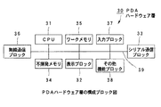
一方、携帯型計算機3のPDAハードウェア層30は、具体的には図3に示すように、入力された画像データを表示する表示手段の機能を備える表示ブロック32を有するとともに、その他、CPU31と、シリアル通信ブロック33と、不揮発メモリ34と、ワークメモリ35と、無線通信ブロック36と、入力ブロック37と、その他機能ブロック38とを有している。PDAハードウェア層30において、これら各部は、バス39に接続されている。
【0041】
表示ブロック32は、各種情報の表示部としての機能を有して構成される。この表示ブロック32によって、例えば、図示しない液晶パネルへの画像データや各種文字データ等の表示を行う。
【0042】
シリアル通信ブロック33は、外部機器とのシリアル通信を行う機能を有して構成される。このシリアル通信ブロック33は、例えば、ビデオゲーム機2のシリアル通信ブロック22に電気的に接続可能とされており、これにより、ビデオゲーム機2とのデータの通信処理を行うことができる。携帯型計算機3には、このシリアル通信ブロック33を介して、ビデオゲーム機2から画像データが供給される。また、ビデオゲーム機2に装着された図示しない記録メディアに記録されているアプリケーションプログラムが供給される。
【0043】
不揮発メモリ34は、各種データを記憶する記憶部である。この不揮発メモリ34には、シリアル通信ブロック33を介してビデオゲーム機2から供給される画像データやアプリケーションプログラムが記憶される。
【0044】
ワークメモリ35は、各種データの作業領域として利用される記憶部である。ワークメモリ35には、不揮発メモリ34と同様に、ビデオゲーム機2から供給される画像データやアプリケーションプログラムが記憶される。
【0045】
無線通信ブロック36は、例えば、IrDA等の赤外線やマイクロ波等によって外部機器との通信を行う機能を備える。
【0046】
入力ブロック37は、入力操作部としての機能を有して構成される。例えば、この入力ブロック37によって、ユーザによる各種情報の入力が可能になる。
【0047】
その他機能ブロック38は、上述したブロック以外により構成されており、例えば、図示しない電源ブロック等が含まれている。
【0048】
CPU31は、上述したような各ブロックを制御する機能を有しており、例えば、上述したソフトウェア層を構成する各種プログラムに応じて各ブロックを制御する。
【0049】
このような構成からなる携帯型計算機3は、ビデオゲーム機2に対して着脱自在とされるように形成され、ビデオゲーム機2とのデータ送受信を行う。また、携帯型計算機3は、上述したビデオゲーム機2に着脱可能とされる図示しない不揮発メモリカードシステムとの互換性を持つように構成される。
【0050】
つぎに、ビデオゲーム機2に接続されるデジタルカメラ4のDCハードウェア層40について説明する。DCハードウェア層40は、具体的には図4に示すように、CPU41と、シリアル通信ブロック42と、画像入力ブロック43と、画像データ記憶ブロック44と、ワークメモリ45とを有している。DCハードウェア層40において、これら各部は、バス46に接続されている。
【0051】
シリアル通信ブロック42は、外部機器とのシリアル通信を行う機能を有して構成される。このシリアル通信ブロック42は、例えば、ビデオゲーム機2のシリアル通信ブロック22に電気的に接続可能とされており、これにより、ビデオゲーム機2とのデータ送受信を行うことができる。デジタルカメラ4には、このシリアル通信ブロック42を介して、ビデオゲーム機2から画像データが供給される。また、デジタルカメラ4は、シリアル通信ブロック42を介して、ビデオゲーム機2へと画像データを供給する。
【0052】
画像入力ブロック43は、画像撮影部としての機能を有して構成され、レンズやシャッタ等の光学系等により構成されている。この画像入力ブロック43によって撮影された画像は、多色かつ高解像度の画像データとして画像データ記憶ブロック44に記録される。
【0053】
画像データ記憶ブロック44は、撮影した画像を記録する部分として構成されている。画像データ記憶ブロック44は、不揮発メモリを内蔵しているか、若しくは着脱自在な記録メディアによって構成される。この画像データ記憶ブロック44には、撮影した画像の他、ビデオゲーム機2からシリアル通信ブロック42を介して供給される画像データが記憶される。
【0054】
ワークメモリ45は、各種データの作業領域として利用される記憶部である。ワークメモリ45には、画像データ記憶ブロック44と同様に、撮影した画像や、ビデオゲーム機2から供給される画像データが記憶される。
【0055】
CPU41は、上述したような各ブロックを制御する機能を有しており、例えば、上述したソフトウェア層を構成する各種プログラムに応じて各ブロックを制御する。
【0056】
データ処理システム1において、ビデオゲーム機2に、携帯型計算機3とデジタルカメラ4とが接続された際の論理的関係は、図5に示すような構造となる。ビデオゲーム機2は、ハードウェア層として、上述したビデオゲーム機ハードウェア層20を有する。また、ソフトウェア層としては、CPU21によって記録メディアブロック24に装着される図示しない記録メディアから読み出した、携帯型計算機3及びデジタルカメラ4との通信を行うとともに、画像データの加工処理を行うための通信及び画像加工アプリケーション50と、携帯型計算機3及びデジタルカメラ4とのシリアル通信を行うためのシリアル通信ドライバ60,70とを有する。ここで、上述したシリアル通信ブロック22は、シリアル通信ドライバ60,70上でデータ送受信を行う。一方、携帯型計算機3は、ハードウェア層として、上述したPDAハードウェア層30を有し、ソフトウェア層としては、ビデオゲーム機2との通信を行うための通信用アプリケーション80と、シリアル通信ドライバ90と、無線通信ドライバ100とを有する。上述したシリアル通信ブロック33及び無線通信ブロック36は、このシリアル通信ドライバ90及び無線通信ドライバ100上でデータ送受信を行う。
【0057】
このようなデータ処理システム1とデータ送受信を行うデジタルカメラ4は、ハードウェア層として、上述したDCハードウェア層40を有し、ソフトウェア層としては、ビデオゲーム機2との通信を行うための通信用アプリケーション110と、シリアル通信ドライバ120とを有する。上述したシリアル通信ブロック42は、ビデオゲーム機2と同様に、シリアル通信ドライバ120上でデータ送受信を行う。
【0058】
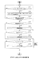
以上説明したような構成を有するデータ処理システム1において、ビデオゲーム機2は、図6に示すような一連の工程によって、デジタルカメラ4からの画像データ、すなわち多色かつ高解像度の画像データを受信する。
【0059】
ビデオゲーム機2は、図6に示すように、ステップS1において、CPU21によって、記録メディアブロック24から図示しない記録メディアに保持された通信及び画像加工アプリケーション50と、携帯型計算機3及びデジタルカメラ4との通信を行うためのシリアル通信ドライバ60,70とを読み出す。
【0060】
次に、ビデオゲーム機2は、ステップS2において、読み出した通信及び画像加工アプリケーション50及びシリアル通信ドライバ60,70を、CPU21によって、メインメモリ25に保持する。
【0061】
続いて、ビデオゲーム機2は、ステップS3において、CPU21によって、シリアル通信ブロック22経由でデジタルカメラ4のシリアル通信ブロック42と通信を開始して通信路を確立し、そして、ステップS4において、この確立した通信路を用いて、デジタルカメラ4から多色かつ高解像度の画像データを受信して、メインメモリ25上に保持する。
【0062】
このデジタルカメラ4からの画像データの受信終了の確認のために、ビデオゲーム機2は、ステップS5において、全ての画像データをデジタルカメラ4から受信したか否かを、CPU21によって、判別する。ここで、CPU21が画像データを全て受信したことを確認した場合には、ビデオゲーム機2は、これらの画像データの受信処理を終了する。また、CPU21が画像データを全て受信していないことを確認した場合には、ビデオゲーム機2は、上述したステップS4からの処理を再び実行する。
【0063】
このようなビデオゲーム機2の処理に対応して、デジタルカメラ4は、図7に示すように、ステップS11において、ビデオゲーム機2よりシリアル通信接続要求があるか否かを判別して待機する。
【0064】
デジタルカメラ4は、このステップS11においてビデオゲーム機2よりシリアル通信接続要求があったことを確認した場合には、ステップS12において、CPU41によって、シリアル通信ブロック42経由でビデオゲーム機2のシリアル通信ブロック22との通信を開始して通信路を確立する。
【0065】
そして、デジタルカメラ4は、ステップS13において、画像データ記憶ブロック44に保持している多色かつ高解像度の画像データを、確立した通信路を用いて、CPU41によりビデオゲーム機2へと送信する。
【0066】
ここで、デジタルカメラ4がこのステップS12及びステップS13において行った処理は、ビデオゲーム機2が先に示したステップS3及びステップS4において行った処理にそれぞれ対応される。
【0067】
この画像データの送信終了の確認のために、デジタルカメラ4は、ステップS14において、全ての画像データをビデオゲーム機2へと送信したか否かを、CPU41によって、判別する。ここで、CPU41がビデオゲーム機2へと画像データを全て送信したことを確認した場合には、デジタルカメラ4は、これらの画像データの送信処理を終了する。また、CPU41がビデオゲーム機2へと画像データを全て送信していないことを確認した場合には、デジタルカメラ4は、上述したステップS13からの処理を再び実行する。
【0068】
以上のようなビデオゲーム機2及びデジタルカメラ4の一連の処理によって、データ処理システム1においては、デジタルカメラ4からビデオゲーム機2へと多色かつ高解像度の画像データが供給される。
【0069】
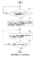
つぎに、ビデオゲーム機2が、上述した一連の処理によりデジタルカメラ4から受信した多色かつ高解像度の画像データに加工処理を施して、携帯型計算機3へと送信するまでの工程を図8及び図9を用いて説明する。
【0070】
ビデオゲーム機2は、図8に示すように、ステップS6において、デジタルカメラ4から供給された多色かつ高解像度の画像データに加工処理を施す。この加工処理は、通信及び画像加工アプリケーション50の動作により行われるもので、後述するように、画像データに対して、解像度変換・減色・トリミング・拡大縮小・軸反転・色反転等を行い、携帯型計算機3での画像データの使用を可能にする少色かつ低解像度の画像データを生成するために行われる。
【0071】
次に、ビデオゲーム機2は、ステップS6において加工した画像データを、ステップS7において、CPU21によりメインメモリ25に保持する。
【0072】
続いて、ビデオゲーム機2は、ステップS8において、CPU21によって、シリアル通信ブロック22経由で携帯型計算機3のシリアル通信ブロック33と通信を開始して、通信路を確立する。
【0073】
そして、ビデオゲーム機2は、ステップS9において、確立した携帯型計算機3との通信路を用いて、CPU21により、加工した画像データを携帯型計算機3へと送信する。
【0074】
この画像データの送信終了の確認のために、ビデオゲーム機2は、ステップS10において、画像データを全て送信したか否かを、CPU21によって、判別する。ここで、ビデオゲーム機2においては、CPU21が画像データを全て送信したことを確認した場合には、この画像データの送信処理を終了し、また、画像データを全て送信していないことを確認した場合には、上述したステップS9からの処理を再び実行する。
【0075】
このようなビデオゲーム機2の処理に対応して、携帯型計算機3は、図9に示すように、ステップS21において、ビデオゲーム機2よりシリアル通信接続要求があるか否かを判別して待機する。
【0076】
携帯型計算機3は、ステップS21においてビデオゲーム機2よりシリアル通信接続要求があったことを確認した場合には、ステップS22において、CPU31により、シリアル通信ブロック33経由でビデオゲーム機2のシリアル通信ブロック22との通信を開始して、通信路を確立する。
【0077】
そして、携帯型計算機3は、ステップS23において、この確立した通信路を用いて、ビデオゲーム機2より受信した画像データを、CPU31が不揮発メモリ34に保持する。
【0078】
ここで、携帯型計算機3がこのステップS22及びステップS23において行った処理は、ビデオゲーム機2が先に示したステップS8及びステップS9において行った処理にそれぞれ対応される。
【0079】
ビデオゲーム機2からの画像データの受信終了の確認のために、携帯型計算機3においては、ステップS24において、画像データを全て受信したか否かを、CPU31によって、判別する。ここで、CPU31がビデオゲーム機2からの画像データを全て受信したことを確認した場合には、携帯型計算機3は、この画像データの受信処理を終了する。また、CPU31がビデオゲーム機2からの画像データを全て受信していないことを確認した場合には、携帯型計算機3は、上述したステップS23からの処理を再び実行する。
【0080】
以上のような一連の処理により、データ処理システム1においては、デジタルカメラ4からの画像データを、ビデオゲーム機2上で携帯型計算機3で使用できるように少色かつ低解像度に加工処理して、携帯型計算機3へと供給することができる。すなわち、データ処理システム1においては、ビデオゲーム機2に対して、デジタルカメラ4を画像入力装置、携帯型計算機3を画像出力装置として用いることができる。携帯型計算機3は、供給された画像データの解像度等が表示ブロック32に表示可能なものに加工されているため、画像データを表示することが可能であり、この画像データを利用するアプリケーションプログラム等の実行も可能となる。
【0081】
つぎに、デジタルカメラ4から複数の画像データをビデオゲーム機2に入力して、これらの画像データの重ね合わせや同一画面への表示等の合成処理をビデオゲーム機2上で行い、合成した画像データを携帯型計算機3へと供給するまでの工程を図10乃至図13を用いて説明する。
【0082】
ビデオゲーム機2は、図10に示すように、ステップS31において、CPU21によって、記録メディアブロック24から図示しない記録メディアに保持された通信及び画像加工アプリケーション50と、携帯型計算機3及びデジタルカメラ4との通信を行うためのシリアル通信ドライバ60,70とを読み出す。
【0083】
次に、ビデオゲーム機2は、ステップS32において、読み出した通信及び画像加工アプリケーション50及びシリアル通信ドライバ60,70を、CPU21によって、メインメモリ25に保持する。
【0084】
続いて、ビデオゲーム機2は、ステップS33において、CPU21によって、シリアル通信ブロック22経由でデジタルカメラ4のシリアル通信ブロック42と通信を開始して通信路を確立し、そして、ステップS34において、この確立した通信路を用いて、デジタルカメラ4から複数の多色かつ高解像度の画像データを受信して、メインメモリ25上に保持する。
【0085】
このデジタルカメラ4からの複数の画像データの受信終了の確認のために、ビデオゲーム機2は、ステップS35において、全ての画像データをデジタルカメラ4から受信したか否かを、CPU21によって、判別する。ここで、CPU21が複数の画像データを全て受信したことを確認した場合には、ビデオゲーム機2は、これらの画像データの受信処理を終了して、図11に示す次のステップS36へと移行する。また、CPU21が複数の画像データを全て受信していないことを確認した場合には、ビデオゲーム機2は、上述したステップS34からの処理を再び実行する。
【0086】
ビデオゲーム機2は、図11に示すように、ステップS36において、デジタルカメラ4から供給された複数の多色かつ高解像度の画像データに合成処理を施す。この合成処理は、上述したように、複数の画像データの重ね合わせや同一画面への表示等を行うものである。なお、この工程において、上述した加工処理も同時に行ってもよいことはいうまでもない。
【0087】
次に、ビデオゲーム機2は、ステップS36において合成した画像データを、ステップS37において、CPU21によりメインメモリ25に保持する。
【0088】
続いて、ビデオゲーム機2は、ステップS38において、CPU21によって、シリアル通信ブロック22経由で携帯型計算機3のシリアル通信ブロック33と通信を開始して、通信路を確立する。
【0089】
そして、ビデオゲーム機2は、ステップS39において、確立した携帯型計算機3との通信路を用いて、CPU21により、合成した画像データを携帯型計算機3へと送信する。
【0090】
この画像データの送信終了の確認のために、ビデオゲーム機2は、ステップS40において、画像データを全て送信したか否かを、CPU21によって、判別する。ここで、ビデオゲーム機2においては、CPU21が画像データを全て送信したことを確認した場合には、この画像データの送信処理を終了し、また、画像データを全て送信していないことを確認した場合には、上述したステップS39からの処理を再び実行する。
【0091】
このようなビデオゲーム機2の処理に対応して、デジタルカメラ4は、図12に示すように、ステップS41において、ビデオゲーム機2よりシリアル通信接続要求があるか否かを判別して待機する。
【0092】
デジタルカメラ4は、このステップS41においてビデオゲーム機2よりシリアル通信接続要求があったことを確認した場合には、ステップS42において、CPU41によって、シリアル通信ブロック42経由でビデオゲーム機2のシリアル通信ブロック22との通信を開始して通信路を確立する。
【0093】
そして、デジタルカメラ4は、ステップS43において、画像データ記憶ブロック44に保持している複数の多色かつ高解像度の画像データを、確立した通信路を用いて、CPU41によりビデオゲーム機2へと送信する。
【0094】
ここで、デジタルカメラ4がこのステップS42及びステップS43において行った処理は、ビデオゲーム機2が先に示したステップS33及びステップS34において行った処理にそれぞれ対応される。
【0095】
この画像データの送信終了の確認のために、デジタルカメラ4は、ステップS44において、全ての画像データをビデオゲーム機2へと送信したか否かを、CPU41によって、判別する。ここで、CPU41がビデオゲーム機2へと複数の画像データを全て送信したことを確認した場合には、デジタルカメラ4は、これらの画像データの送信処理を終了する。また、CPU41がビデオゲーム機2へと複数の画像データを全て送信していないことを確認した場合には、デジタルカメラ4は、上述したステップS43からの処理を再び実行する。
【0096】
一方、携帯型計算機3は、図13に示すように、ステップS51において、ビデオゲーム機2よりシリアル通信接続要求があるか否かを判別して待機する。
【0097】
携帯型計算機3は、ステップS51においてビデオゲーム機2よりシリアル通信接続要求があったことを確認した場合には、ステップS52において、CPU31により、シリアル通信ブロック33経由でビデオゲーム機2のシリアル通信ブロック22との通信を開始して、通信路を確立する。
【0098】
そして、携帯型計算機3は、ステップS53において、この確立した通信路を用いて、ビデオゲーム機2より受信した画像データを、CPU31が不揮発メモリ34に保持する。
【0099】
ここで、携帯型計算機3がこのステップS52及びステップS53において行った処理は、ビデオゲーム機2が先に示したステップS38及びステップS39において行った処理にそれぞれ対応される。
【0100】
ビデオゲーム機2からの画像データの受信終了の確認のために、携帯型計算機3においては、ステップS54において、画像データを全て受信したか否かを、CPU31によって、判別する。ここで、CPU31がビデオゲーム機2からの画像データを全て受信したことを確認した場合には、携帯型計算機3は、この画像データの受信処理を終了する。また、CPU31がビデオゲーム機2からの画像データを全て受信していないことを確認した場合には、携帯型計算機3は、上述したステップS53からの処理を再び実行する。
【0101】
以上のような一連の処理によって、データ処理システム1においては、デジタルカメラ4からビデオゲーム機2へと供給された複数の画像データを、ビデオゲーム機2上で合成処理して、携帯型計算機3へと供給することができる。すなわち、データ処理システム1においては、デジタルカメラ4から複数の画像データが供給されたときでも、これらの複数の画像データを携帯型計算機3の表示ブロック32に表示することができる。
【0102】
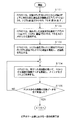
ところで、ビデオゲーム機2は、上述したビデオゲーム機2上での画像データに対する加工・合成処理を、通信及び画像加工アプリケーション50を動作させて、入力ブロック23による入力操作に応じて処理内容を変化させながら行うことができ、その結果をリアルタイムにモニタ5に表示することができる。この際の処理内容が変化する一連の工程を図14を用いて説明する。なお、ここではデジタルカメラ4から供給された画像データに、解像度変換、減色、トリミング処理から選択して加工処理を施すときの工程を主に示し、その他の加工・合成処理については省略する。
【0103】
ビデオゲーム機2は、図14に示すように、ステップS61において、入力ブロック23を構成する図示しないコントローラにより入力データがあるか否かを判別して待機する。
【0104】
ビデオゲーム機2は、ステップS61においてコントローラからの入力データがあったことを確認した場合には、ステップS62において、CPU21により、入力データをメインメモリ25へ保持し、その保持した入力データ列をコマンドとして文法解析する。
【0105】
ビデオゲーム機2は、ステップS62において解析したコマンドに対応する加工・合成処理が、通信及び画像加工アプリケーション50に存在し、実行可能なものであるか否かを、ステップS63において判別する。ここで、解析したコマンドに対応する加工・合成処理が存在するものであることを確認した場合には、ビデオゲーム機2は、次のステップS64へと移行する。また、解析したコマンドに対応する加工・合成処理が存在しないことを確認した場合には、ビデオゲーム機2は、上述したステップS61からの処理を再び実行する。
【0106】
ビデオゲーム機2は、ステップS64において、解析したコマンドが、解像度変換コマンドであるか否かを判別し、解像度変換コマンドであった場合には、ステップS65における解像度変換処理を行い、画像データを携帯型計算機3において使用できる解像度に変換する。また、解像度変換コマンドでなかった場合には、ステップS66において、減色コマンドであるか否かを判別する。ここで、減色コマンドであった場合には、ビデオゲーム機2は、ステップS67における減色処理を行い、画像データを携帯型計算機3において使用できるように減色する。一方、減色コマンドでなかった場合には、ステップS68において、トリミングコマンドであるか否かを判別する。トリミングコマンドであった場合には、ビデオゲーム機2は、ステップS69におけるトリミング処理を行う。そして、トリミング処理でなかった場合には、その他の拡大縮小等の処理工程に移行し、加工・合成処理を終了する。
【0107】
このようにデータ処理システム1においては、ビデオゲーム機2上での画像データの加工・合成処理を、使用者の入力操作に応じて任意に変化させて行うことができる。また、これらの処理結果は、ビデオゲーム機2に接続しているモニタ5にリアルタイムに表示することが可能であり、データ処理システム1においては、デジタルカメラ4からの画像データを、ビデオゲーム機2上で加工・合成処理して、使用者が要求を満足するような画像データを生成したことを確認した後、携帯型計算機3へと供給することができる。
【0108】
データ処理システム1においては、上述したように、デジタルカメラ4からビデオゲーム機2を介して携帯型計算機3へと画像データを送信するばかりではなく、携帯型計算機3からの画像データをビデオゲーム機2を介してデジタルカメラ4へと送信することもできる。このときの一連の処理を図15乃至図18を用いて説明する。
【0109】
ビデオゲーム機2は、図15に示すように、ステップS71において、CPU21によって、記録メディアブロック24から図示しない記録メディアに保持された通信及び画像加工アプリケーション50と、携帯型計算機3及びデジタルカメラ4との通信を行うためのシリアル通信ドライバ60,70とを読み出す。
【0110】
次に、ビデオゲーム機2は、ステップS72において、読み出した通信及び画像加工アプリケーション50及びシリアル通信ドライバ60,70を、CPU21によって、メインメモリ25に保持する。
【0111】
続いて、ビデオゲーム機2は、ステップS73において、CPU21によって、シリアル通信ブロック22経由で携帯型計算機3のシリアル通信ブロック33と通信を開始して通信路を確立する。
【0112】
ビデオゲーム機2は、ステップS74において、この確立した通信路を用いて携帯型計算機3から画像データを受信して、メインメモリ25上に保持する。
【0113】
この携帯型計算機3からの画像データの受信終了の確認のために、ビデオゲーム機2は、ステップS75において、全ての画像データを携帯型計算機3から受信したか否かを、CPU21によって、判別する。ここで、CPU21が画像データを全て受信したことを確認した場合には、ビデオゲーム機2は、これらの画像データの受信処理を終了する。また、CPU21が画像データを全て受信していないことを確認した場合には、ビデオゲーム機2は、上述したステップS74からの処理を再び実行する。
【0114】
このようなビデオゲーム機2の処理に対応して、携帯型計算機3は、図16に示すように、ステップS81において、ビデオゲーム機2よりシリアル通信接続要求があるか否かを判別して待機する。
【0115】
携帯型計算機3は、このステップS81においてビデオゲーム機2よりシリアル通信接続要求があったことを確認した場合には、ステップS82において、CPU31によって、シリアル通信ブロック33経由でビデオゲーム機2のシリアル通信ブロック22との通信を開始して通信路を確立する。
【0116】
そして、携帯型計算機3は、ステップS83において、不揮発メモリ34に保持している画像データを、確立した通信路を用いて、CPU31によりビデオゲーム機2へと送信する。
【0117】
ここで、携帯型計算機3がこのステップS82及びステップS83において行った処理は、ビデオゲーム機2が先に示したステップS73及びステップS74において行った処理にそれぞれ対応される。
【0118】
この画像データの送信終了の確認のために、携帯型計算機3は、ステップS84において、全ての画像データをビデオゲーム機2へと送信したか否かを、CPU31によって、判別する。ここで、CPU31がビデオゲーム機2へと画像データを全て送信したことを確認した場合には、携帯型計算機3は、これらの画像データの送信処理を終了する。また、CPU31がビデオゲーム機2へと画像データを全て送信していないことを確認した場合には、携帯型計算機3は、上述したステップS83からの処理を再び実行する。
【0119】
以上のようなビデオゲーム機2及び携帯型計算機3の一連の処理によって、データ処理システム1においては、携帯型計算機3からビデオゲーム機2へと画像データが供給される。
【0120】
つぎに、ビデオゲーム機2が、上述した一連の処理により携帯型計算機3より受信した画像データに加工処理を施して、デジタルカメラ4へと送信するまでの工程を図17及び図18を用いて説明する。
【0121】
ビデオゲーム機2は、図17に示すように、ステップS76において、携帯型計算機3から供給された画像データに加工処理を施す。この加工処理は、通信及び画像加工アプリケーション50の動作により行われるもので、後述するように、画像データに対して、解像度変換・色補間・トリミング・拡大縮小・軸反転・色反転等を行うものである。
【0122】
次に、ビデオゲーム機2は、ステップS76において加工した画像データを、ステップS77において、CPU21によりメインメモリ25に保持する。
【0123】
続いて、ビデオゲーム機2は、ステップS78において、CPU21によって、シリアル通信ブロック22経由でデジタルカメラ4のシリアル通信ブロック42と通信を開始して、通信路を確立する。
【0124】
そして、ビデオゲーム機2は、ステップS79において、確立したデジタルカメラ4との通信路を用いて、CPU21により、加工した画像データをデジタルカメラ4へと送信する。
【0125】
この画像データの送信終了の確認のために、ビデオゲーム機2は、ステップS80において、画像データを全て送信したか否かを、CPU21によって、判別する。ここで、ビデオゲーム機2においては、CPU21が画像データを全て送信したことを確認した場合には、この画像データの送信処理を終了し、また、画像データを全て送信していないことを確認した場合には、上述したステップS79からの処理を再び実行する。
【0126】
このようなビデオゲーム機2の処理に対応して、デジタルカメラ4は、図18に示すように、ステップS91において、ビデオゲーム機2よりシリアル通信接続要求があるか否かを判別して待機する。
【0127】
デジタルカメラ4は、ステップS91においてビデオゲーム機2よりシリアル通信接続要求があったことを確認した場合には、ステップS92において、CPU41により、シリアル通信ブロック42経由でビデオゲーム機2のシリアル通信ブロック22との通信を開始して、通信路を確立する。
【0128】
そして、デジタルカメラ4は、ステップS93において、この確立した通信路を用いて、ビデオゲーム機2より受信した画像データを、CPU41が画像データ記憶ブロック44に保持する。
【0129】
ここで、デジタルカメラ4がこのステップS92及びステップS93において行った処理は、ビデオゲーム機2が先に示したステップS78及びステップS79において行った処理にそれぞれ対応される。
【0130】
ビデオゲーム機2からの画像データの受信終了の確認のために、デジタルカメラ4においては、ステップS94において、画像データを全て受信したか否かを、CPU41によって、判別する。ここで、CPU41がビデオゲーム機2からの画像データを全て受信したことを確認した場合には、デジタルカメラ4は、この画像データの受信処理を終了する。また、CPU41がビデオゲーム機2からの画像データを全て受信していないことを確認した場合には、デジタルカメラ4は、上述したステップS93からの処理を再び実行する。
【0131】
以上のような一連の処理により、データ処理システム1においては、携帯型計算機3からの画像データを、ビデオゲーム機2上で加工処理して、デジタルカメラ4へと供給することができる。すなわち、データ処理システム1においては、ビデオゲーム機2に対して、携帯型計算機3を画像入力装置、デジタルカメラ4を画像出力装置としても用いることができる。
【0132】
つぎに、携帯型計算機3から複数の画像データをビデオゲーム機2に入力して、これらの画像データの重ね合わせや同一画面への表示等の合成処理をビデオゲーム機2上で行い、合成した画像データをデジタルカメラ4へと供給するまでの工程を図19乃至図22を用いて説明する。
【0133】
ビデオゲーム機2は、図19に示すように、ステップS101において、CPU21によって、記録メディアブロック24から図示しない記録メディアに保持された通信及び画像加工アプリケーション50と、携帯型計算機3及びデジタルカメラ4との通信を行うためのシリアル通信ドライバ60,70とを読み出す。
【0134】
次に、ビデオゲーム機2は、ステップS102において、読み出した通信及び画像加工アプリケーション50及びシリアル通信ドライバ60,70を、CPU21によって、メインメモリ25に保持する。
【0135】
続いて、ビデオゲーム機2は、ステップS103において、CPU21によって、シリアル通信ブロック22経由で携帯型計算機3のシリアル通信ブロック33と通信を開始して通信路を確立し、そして、ステップS104において、この確立した通信路を用いて、携帯型計算機3から複数の画像データを受信して、メインメモリ25上に保持する。
【0136】
この携帯型計算機3からの複数の画像データの受信終了の確認のために、ビデオゲーム機2は、ステップS105において、全ての画像データを携帯型計算機3から受信したか否かを、CPU21によって、判別する。ここで、CPU21が複数の画像データを全て受信したことを確認した場合には、ビデオゲーム機2は、これらの画像データの受信処理を終了して、図20に示す次のステップS106へと移行する。また、CPU21が複数の画像データを全て受信していないことを確認した場合には、ビデオゲーム機2は、上述したステップS104からの処理を再び実行する。
【0137】
ビデオゲーム機2は、図20に示すように、ステップS106において、携帯型計算機3から供給された複数の画像データに合成処理を施す。この合成処理は、上述したように、複数の画像データの重ね合わせや同一画面への表示等を行うものである。また、上述した加工処理を合わせて行ってもよい。
【0138】
次に、ビデオゲーム機2は、ステップS106において合成した画像データを、ステップS107において、CPU21によりメインメモリ25に保持する。
【0139】
続いて、ビデオゲーム機2は、ステップS108において、CPU21によって、シリアル通信ブロック22経由でデジタルカメラ4のシリアル通信ブロック42と通信を開始して、通信路を確立する。
【0140】
そして、ビデオゲーム機2は、ステップS109において、確立したデジタルカメラ4との通信路を用いて、CPU21により、合成した画像データをデジタルカメラ4へと送信する。
【0141】
この画像データの送信終了の確認のために、ビデオゲーム機2は、ステップS110において、画像データを全て送信したか否かを、CPU21によって、判別する。ここで、ビデオゲーム機2においては、CPU21が画像データを全て送信したことを確認した場合には、この画像データの送信処理を終了し、また、画像データを全て送信していないことを確認した場合には、上述したステップS109からの処理を再び実行する。
【0142】
このようなビデオゲーム機2の処理に対応して、携帯型計算機3は、図21に示すように、ステップS111において、ビデオゲーム機2よりシリアル通信接続要求があるか否かを判別して待機する。
【0143】
携帯型計算機3は、このステップS111においてビデオゲーム機2よりシリアル通信接続要求があったことを確認した場合には、ステップS112において、CPU31によって、シリアル通信ブロック33経由でビデオゲーム機2のシリアル通信ブロック22との通信を開始して通信路を確立する。
【0144】
そして、携帯型計算機3は、ステップS113において、不揮発メモリ34に保持している複数の画像データを、確立した通信路を用いて、CPU31によりビデオゲーム機2へと送信する。
【0145】
ここで、携帯型計算機3がこのステップS112及びステップS113において行った処理は、ビデオゲーム機2が先に示したステップS103及びステップS104において行った処理にそれぞれ対応される。
【0146】
この画像データの送信終了の確認のために、携帯型計算機3は、ステップS114において、全ての画像データをビデオゲーム機2へと送信したか否かを、CPU31によって、判別する。ここで、CPU31がビデオゲーム機2へと複数の画像データを全て送信したことを確認した場合には、携帯型計算機3は、これらの画像データの送信処理を終了する。また、CPU31がビデオゲーム機2へと複数の画像データを全て送信していないことを確認した場合には、携帯型計算機3は、上述したステップS113からの処理を再び実行する。
【0147】
一方、デジタルカメラ4は、図22に示すように、ステップS121において、ビデオゲーム機2よりシリアル通信接続要求があるか否かを判別して待機する。
【0148】
デジタルカメラ4は、ステップS121においてビデオゲーム機2よりシリアル通信接続要求があったことを確認した場合には、ステップS122において、CPU41により、シリアル通信ブロック42経由でビデオゲーム機2のシリアル通信ブロック22との通信を開始して、通信路を確立する。
【0149】
そして、デジタルカメラ4は、ステップS123において、この確立した通信路を用いて、ビデオゲーム機2より受信した画像データを、CPU41が画像データ記憶ブロック44に保持する。
【0150】
ここで、デジタルカメラ4がこのステップS122及びステップS123において行った処理は、ビデオゲーム機2が先に示したステップS108及びステップS109において行った処理にそれぞれ対応される。
【0151】
ビデオゲーム機2からの画像データの受信終了の確認のために、デジタルカメラ4においては、ステップS124において、画像データを全て受信したか否かを、CPU41によって、判別する。ここで、CPU41がビデオゲーム機2からの画像データを全て受信したことを確認した場合には、デジタルカメラ4は、この画像データの受信処理を終了する。また、CPU41がビデオゲーム機2からの画像データを全て受信していないことを確認した場合には、デジタルカメラ4は、上述したステップS123からの処理を再び実行する。
【0152】
以上のような一連の処理によって、データ処理システム1においては、携帯型計算機3からビデオゲーム機2へと供給された複数の画像データを、ビデオゲーム機2上で合成処理して、デジタルカメラ4へと供給することができる。
【0153】
この携帯型計算機3からの画像データをビデオゲーム機2を介してデジタルカメラ4へち供給する場合においても、ビデオゲーム機2は、上述したビデオゲーム機2上での画像データに対する加工・合成処理を、通信及び画像加工アプリケーション50を動作させて、入力ブロック23による入力操作に応じて処理内容を変化させながら行うことができ、その結果をリアルタイムにモニタ5に表示することができる。この際の処理内容が変化する一連の工程を図23を用いて説明する。なお、ここでは携帯型計算機3から供給された画像データに、解像度変換、色補間、トリミング処理から選択して加工処理を施すときの工程を主に示し、その他の加工・合成処理については省略する。
【0154】
ビデオゲーム機2は、図23に示すように、ステップS131において、入力ブロック23を構成する図示しないコントローラにより入力データがあるか否かを判別して待機する。
【0155】
ビデオゲーム機2は、ステップS131においてコントローラからの入力データがあったことを確認した場合には、ステップS132において、CPU21により、入力データをメインメモリ25へ保持し、その保持した入力データ列をコマンドとして文法解析する。
【0156】
ビデオゲーム機2は、ステップS132において解析したコマンドに対応する加工・合成処理が、通信及び画像加工アプリケーション50に存在し、実行可能なものであるか否かを、ステップS133において判別する。ここで、解析したコマンドに対応する加工・合成処理が存在するものであることを確認した場合には、ビデオゲーム機2は、次のステップS134へと移行する。また、解析したコマンドに対応する加工・合成処理が存在しないことを確認した場合には、ビデオゲーム機2は、上述したステップS131からの処理を再び実行する。
【0157】
ビデオゲーム機2は、ステップS134において、解析したコマンドが、解像度変換コマンドであるか否かを判別し、解像度変換コマンドであった場合には、ステップS135における解像度変換処理を行い、画像データをデジタルカメラ4に対応する解像度に変換する。また、解像度変換コマンドでなかった場合には、ステップS136において、色補間コマンドであるか否かを判別する。ここで、色補間コマンドであった場合には、ビデオゲーム機2は、ステップS137における色補間処理を行う。色補間コマンドでなかった場合には、ステップS138において、トリミングコマンドであるか否かを判別する。トリミングコマンドであった場合には、ビデオゲーム機2は、ステップS139におけるトリミング処理を行い、トリミング処理でなかった場合には、その他の拡大縮小等の処理工程に移行し、加工・合成処理を終了する。
【0158】
このようにデータ処理システム1における携帯型計算機3とデジタルカメラ4との間の画像データ送受信においては、いずれの方向であってもビデオゲーム機2上での画像データ加工・合成処理を、使用者の入力操作に応じて任意に変化させて行うことができる。また、これらの処理結果は、ビデオゲーム機2に接続しているモニタ5にリアルタイムに表示することが可能であり、データ処理システム1においては、携帯型計算機3からの画像データに対しても、ビデオゲーム機2上で加工・合成処理して、使用者が要求を満足するような画像データを生成したことを確認した後、デジタルカメラ4へと供給することができる。
【0159】
つぎに、ビデオゲーム機2に対して、携帯型計算機3及びデジタルカメラ4の両方から画像データが供給され、それらの画像データにビデオゲーム機2上で加工・合成処理を施して、携帯型計算機3へと出力する工程を説明する。
【0160】
データ処理システム1においては、この工程を、上述した図10乃至図13、図19、図21に示した工程を組み合わせることによって行うことができる。
【0161】
ビデオゲーム機2は、まず図10に示す各工程を経ることによって、デジタルカメラ4から複数の画像データを受信する。
【0162】
すなわち、ビデオゲーム機2は、図示しない記録メディアに保持された通信及び画像加工アプリケーション50と、シリアル通信ドライバ60,70とを読み出し、メインメモリ25に保持する。そして、ビデオゲーム機2は、デジタルカメラ4との通信路を確立して、デジタルカメラ4から複数の画像データを受信して、メインメモリ25上に保持する。ビデオゲーム機2は、デジタルカメラ4から複数の画像データを全て受信したことを確認した後、図19に示す各工程へと移行する。
【0163】
ビデオゲーム機2は、図19における各工程を経ることによって、デジタルカメラ4と同様に、携帯型計算機3から複数の画像データを受信する。
【0164】
すなわち、ビデオゲーム機2は、図示しない記録メディアに保持された通信及び画像加工アプリケーション50と、シリアル通信ドライバ60,70とを読み出し、メインメモリ25に保持する。そして、ビデオゲーム機2は、携帯型計算機3との通信路を確立して、携帯型計算機3から複数の画像データを受信して、メインメモリ25上に保持する。ビデオゲーム機2は、携帯型計算機3から複数の画像データを全て受信したことを確認したビデオゲーム機2は、次に図11に示す工程を行う。
【0165】
ビデオゲーム機2は、携帯型計算機3及びデジタルカメラ4から受信した複数の画像データに対して、加工・合成処理を施し、得られた画像データをメインメモリ25に保持する。これらの加工・合成処理は、上述した処理と同様のものであり、携帯型計算機3において使用可能な画像データを生成する。また、ビデオゲーム機2は、これらの加工・合成処理を、図14及び図23に示したように、コントローラからの入力操作に応じて行うことができ、処理結果をリアルタイムにモニタ5に表示することができる。
【0166】
そして、ビデオゲーム機2は、携帯型計算機3との通信路を確立し、画像データを携帯型計算機3へと送信する。
【0167】
このようなビデオゲーム機2の処理に対応して、携帯型計算機3及びデジタルカメラ4は、図12、図21、図13に示す各工程を行う。
【0168】
すなわち、デジタルカメラ4は、図12に示すように、ビデオゲーム機2との通信路を確立して、画像データ記憶ブロックに保持している複数の画像データを、ビデオゲーム機2へと送信する。
【0169】
その後、携帯型計算機3は、デジタルカメラ4と同様に、図21に示す各工程を行う。携帯型計算機3は、ビデオゲーム機2との通信路を確立して、不揮発メモリ34に保持している複数の画像データを、ビデオゲーム機2へと送信する。
【0170】
このようにして、携帯型計算機3及びデジタルカメラ4がビデオゲーム機2へと複数の画像データをビデオゲーム機2へ送信し終えると、携帯型計算機3は、図13に示す各工程を行い、ビデオゲーム機2からの画像データを受信する。
【0171】
すなわち、携帯型計算機3は、ビデオゲーム機2との通信路を確立して、ビデオゲーム機2上で加工・合成処理された画像データを受信し、一連の処理を終了する。
【0172】
以上のように、データ処理システム1においては、携帯型計算機3及びデジタルカメラ4からビデオゲーム機2へと複数の画像データを送信することができ、これらの画像データにビデオゲーム機2上で加工・合成処理を施して、携帯型計算機3へと送信することができる。
【0173】
また、データ処理システム1においては、図13の各工程を図18に示す各工程に変更して同様の処理を行うことで、送信先として携帯型計算機3のみではなく、デジタルカメラ4へ画像データを送信することもできる。
【0174】
つぎに、ビデオゲーム機2から携帯型計算機3へと送信した画像データを使用するアプリケーションソフトウェアを、ビデオゲーム機2から携帯型計算機3へと送信する工程を、図24及び図25を用いて説明する。
【0175】
ビデオゲーム機2は、図24に示すように、ステップS141において、携帯型計算機3への画像データ転送処理を行う。この画像データ転送処理とは、上述したように、デジタルカメラ4又は携帯型計算機3、デジタルカメラ4の両方からビデオゲーム機2へと送信された画像データを携帯型計算機3へと供給する際の処理のことである。
【0176】
次に、ビデオゲーム機2は、ステップS142において、記録メディアブロック24から図示しない記録メディアに記録されているアプリケーションソフトウェアを読み出す。このアプリケーションソフトウェアは、携帯型計算機3へ供給された画像データを使用して、携帯型計算機3上で動作するものである。
【0177】
そして、ビデオゲーム機2は、ステップS143におけるアプリケーションソフトウェア転送処理を行う。このアプリケーションソフトウェア転送処理は、上述した画像データ転送処理と略同様な工程を経て行われ、シリアル通信ブロック22を介して行われる。この工程によって、ビデオゲーム機2は、携帯型計算機3へとアプリケーションソフトウェアを供給する。
【0178】
次に、ビデオゲーム機2は、ステップS144において、携帯型計算機3に対して、転送したアプリケーションソフトウェアを起動するように指示を出し、一連の送信処理を終了する。
【0179】
このビデオゲーム機2の処理に対応して、携帯型計算機3は、図25に示すように、ステップS151において、画像データ受信処理を行う。この画像データ受信処理は、ビデオゲーム機2から画像データを受信する際の一連の処理のことである。
【0180】
続いて、携帯型計算機3は、ステップS152において、ビデオゲーム機2からのアプリケーションソフトウェア受信処理を行う。このアプリケーションソフトウェア受信処理は、上述した画像データ受信処理と略同様な工程を経て行われ、シリアル通信ブロック33を介して行われる。この工程によって、携帯型計算機3は、ビデオゲーム機2からアプリケーションソフトウェアを受信する。
【0181】
次に、携帯型計算機3は、ステップS153において、ビデオゲーム機2から供給されたアプリケーションソフトウェアを起動するように、ビデオゲーム機2から指示を受ける。
【0182】
ここで、携帯型計算機3がこのステップS152及びステップS153において行った処理は、ビデオゲーム機2が先に示したステップS143及びステップS144において行った処理にそれぞれ対応される。
【0183】
この起動指示を受信した携帯型計算機3は、ステップS154において、アプリケーションソフトウェアを起動して、ビデオゲーム機2から受信した画像データを表示ブロック32に表示したり、その他の各種データ処理を行う。
【0184】
このようにして、データ処理システム1においては、ビデオゲーム機2に装着される記録メディアから、携帯型計算機3上で動作するアプリケーションソフトウェアを読み出して、携帯型計算機3へと供給することができ、携帯型計算機3に対して、画像データを取り込んで使用する機能を提供することができる。また、データ処理システム1においては、このアプリケーションソフトウェアと、上述した通信及び画像加工アプリケーション50やシリアル通信ドライバ60,70等を1つの記録メディアによって供給することも可能である。
【0185】
以上説明してきたように、データ処理システム1においては、ビデオゲーム機2に対して、直接接続することが困難である携帯型計算機3及びデジタルカメラ4を同時に接続することで、この携帯型計算機3とデジタルカメラ4との間で画像データの送受信を行うことができる。
【0186】
また、データ処理システム1においては、携帯型計算機3とデジタルカメラ4といった解像度の異なる機器間のデータ送受信に際して、ビデオゲーム機2により、画像データの解像度変換、減色や色補間、各種のフォーマット変換等の画像データ処理を行うことができ、携帯型計算機3とデジタルカメラ4との間のデータ送受信を可能にする。
【0187】
さらに、データ処理システム1においては、ビデオゲーム機2の高速なグラフィック表示機能を利用することで、画像データの加工・合成処理の結果をリアルタイムにモニタ5に表示することができる。したがって、データ処理システム1においては、使用者が画像データの加工・合成処理の良し悪しを確認した上で、データ送受信を行うことができ、使用者への適切なフィードバックを提供することができる。
【0188】
さらにまた、データ処理システム1においては、携帯型計算機3からの複数の画像データと、デジタルカメラ4からの複数の画像データとをビデオゲーム機2へと供給して、これらの画像データをビデオゲーム機2上で加工・合成処理し、携帯型計算機3又はデジタルカメラ4へと転送することができる。したがって、データ処理システム1は、複数の画像ソースにも対応するものであって、複数の画像ソースからの編集処理を容易に提供することができる。
【0189】
また、データ処理システム1においては、携帯型計算機3上で動作するアプリケーションソフトウェアをビデオゲーム機2から供給し、ビデオゲーム機2が携帯型計算機3に対して、アプリケーションソフトウェアの起動指示を行う。このことにより、データ処理システム1においては、携帯型計算機3に対して、外部の画像データを取り込んで使用する機能を提供することができる。
【0190】
なお、ビデオゲーム機2において、通信及び画像加工アプリケーション50やシリアル通信ドライバ60,70、携帯型計算機3へ供給するアプリケーションソフトウェア等は、CD−ROM等の記録メディアに記録されている必要はなく、例えば、外部との通信によって取得するようにしてもよい。
【0191】
つぎに、上述した実施の形態として示したデータ処理システムを、より具体的にエンタテインメントシステムとして示した具体例を図26乃至図30を用いて説明する。この図26乃至図30においては、上述したデータ処理システム1を構成するビデオゲーム機2及び携帯型計算機3は、ビデオゲーム装置301及び携帯用電子機器400よりなるエンタテインメントシステムとして構成されている。
【0192】
すなわち、ビデオゲーム機2は、ビデオゲーム装置301に、携帯型計算機3は、携帯用電子機器400に対応される。具体的には、ビデオゲーム機2とビデオゲーム装置301との対応については、上述したビデオゲーム機2のCPU21、シリアル通信ブロック22、入力ブロック23は、図29に示すビデオゲーム装置301のCPU351、メモリカード挿入部308A,308B又はシリアルI/Oインタフェース(SIO)397、コントローラ320にそれぞれ対応される。また、携帯型計算機3のCPU31、表示ブロック32、シリアル通信ブロック33は、図30(A)に示す制御手段441、表示手段444、接続コネクタ442にそれぞれ対応される。
【0193】
ビデオゲーム装置301は、図26及び図27に示すように、記録メディアに記録されているアプリケーションプログラムを読み出し、使用者(ゲームプレイヤ)からの指示に応じて実行するためのものである。ここで、ゲームの実行とは、例えば、主としてゲームの進行、表示、及び音声制御することをいう。
【0194】
ビデオゲーム装置301の本体302は、ほぼ四角形状の筐体に収容されており、その中央部にビデオゲームや、通信及び画像加工アプリケーション50、携帯用電子機器400で使用するアプリケーションソフトウェア等のアプリケーションプログラムを供給するための記録メディアである、CD−ROM等の光ディスクが装着されるディスク装着部303と、ビデオゲームを任意にリセットするためのリセットスイッチ304と、電源スイッチ305と、上述した光ディスクの装着を操作するためのディスク操作スイッチ306と、2つのスロット部307A,307Bとを備えている。
【0195】
なお、ビデオゲーム装置301は、アプリケーションプログラムを記録メディアから供給されるのみならず、通信回線を介して供給されるようにも構成されている。
【0196】
スロット部307A,307Bには、携帯用電子機器400やコントローラ320を接続することができる。また、このスロット部307A,307Bには、図示しないが、メモリカードシステムも接続することができる。
【0197】
コントローラ320は、第1、第2の操作部321,322と、Lボタン323L,Rボタン323Rと、スタートボタン324と、選択ボタン325と、アナログ的操作が可能な操作部331,332と、この操作部331,332の操作モードを選択するモード選択スイッチ333と、選択された操作モードを表示するための表示部334とを有している。また、図示しないものの、コントローラ320の内部には、振動付与機構が設けられている。この振動付与機構は、例えば、ビデオゲームの進行等に応じてコントローラ20に振動を付与する。このコントローラ320は、接続部326によって本体302のスロット部307Bに電気的に接続されている。
【0198】
例えば、スロット部307A,307Bに2つのコントローラ320を接続することにより、2人の使用者がこのエンタテインメントシステムを共有することができ、すなわち、例えば、対戦ゲーム等を行うことができる。なお、スロット部307A,307Bはこのように2系統に限定されるものではない。
【0199】
携帯用電子機器400は、図28(A)乃至図28(C)に示すように、ハウジング401を有して構成され、各種情報入力のための操作部420と、液晶表示装置(LCD)等からなる表示部430と、ワイヤレス通信手段448により例えば、赤外線によるワイヤレス通信を行うための窓部440とが設けられている。
【0200】
ハウジング401は、上シェル401a及び下シェル401bからなり、メモリ素子等を搭載した基板を内部に収納している。このハウジング401は、ビデオゲーム装置301の本体302のスロット部307A,307Bに挿入され得る形状とされている。
【0201】
窓部440は、略々半円形状に形成されたハウジング401の他端部分に設けられている。表示部430は、ハウジング401を構成している上シェル401aに略々半分の領域を占めて、窓部440の近傍に位置して設けられている。
【0202】
操作部420は、イベント入力や各種選択等を行うための1個又は複数の操作子421,422を有しており、窓部440と同様に上シェル401aに形成され、そして、窓部440の反対側とされ略々半分の領域を占めて設けられている。そして、この操作部420は、ハウジング401に対して回動可能に支持された蓋部材410上に構成されている。ここで、操作子421,422は、この蓋部材410の上面側より下面側に亘ってこの蓋部材410を貫通して配設されている。そして、これら操作子421,422は、蓋部材410の上面部に対して出没する方向に移動可能となされて蓋部材410によって支持されている。
【0203】
携帯用電子機器400は、ハウジング401内であって蓋部材410の配設位置に対向位置されて基板を有し、さらにその基板上にスイッチ押圧部を設けている。スイッチ押圧部は、蓋部材410が閉蓋された状態において、各操作子421,422の位置に対応する位置に設けられている。これにより、各操作子421,422が押圧されると、スイッチ押圧部が例えば、ダイヤフラムスイッチの如き押圧スイッチを押圧する。
【0204】
このように蓋部材410に操作部420等が形成されてなる携帯用電子機器400は、図26に示すように、蓋部材410が開かれた状態でビデオゲーム装置301の本体302に装着される。
【0205】
以上のようにビデオゲーム装置301及び携帯用電子機器400の外観が構成されている。
【0206】
このビデオゲーム装置301及び携帯用電子機器400の回路構成等は、図29及び図30に示すようになされている。
【0207】
ビデオゲーム装置301は、図29に示すように、中央演算処理装置(CPU:Central Processing Unit)351及びその周辺装置等からなる制御系350と、フレームバッファ363に描画を行う画像処理装置(GPU:Graphic Processing Unit)362等からなるグラフィックシステム360と、楽音や効果音等を発生する音声処理装置(SPU:Sound Processing Unit)等からなるサウンドシステム370と、アプリケーションプログラムが記録されている光ディスクの制御を行う光ディスク制御部380と、使用者からの指示が入力されるコントローラ320からの信号及びゲームの設定等を記憶する図示しないメモリカードや携帯用電子機器400からのデータの入出力を制御する通信制御部390と、上述した各部が接続されているバス395と、他の機器とのインタフェース部と構成するパラレルI/Oインタフェース(PIO)396と、シリアルI/Oインタフェース(SIO)397とを備えている。
【0208】
制御系350は、CPU351と、割り込み制御やダイレクトメモリアクセス(DMA:Dinamic Memory Access)転送の制御等を行う周辺装置制御部352と、ランダムアクセスメモリ(RAM:Random Access Memory)からなるメインメモリ(主記憶装置)353と、メインメモリ353、グラフィックシステム360、サウンドシステム370等の管理を行ういわゆるオペレーティングシステム等のプログラムが格納されたリードオンリーメモリ(ROM:Read Only Memory)354とを備えている。
【0209】
CPU351は、ROM354に記憶されているオペレーティングシステムを実行することによって、このビデオゲーム装置301の全体を制御するものである。
【0210】
例えば、このビデオゲーム装置301は、電源が投入されると、制御系350のCPU351がROM354に記憶されているオペレーティングシステムを実行することにより、CPU351が、グラフィックシステム360、サウンドシステム370等の制御を開始する。例えば、オペレーティングシステムが実行されると、CPU351は、動作確認等のビデオゲーム装置301の全体の初期化を行った後、光ディスク制御部380を制御して、光ディスクに記録されているアプリケーションプログラムを実行する。このアプリケーションプログラムの実行により、CPU351は、使用者からの入力に応じて、グラフィックシステム360、サウンドシステム370等を制御して、画像の表示、効果音、楽音の発生を制御する。
【0211】
なお、CPU351は、上述したビデオゲーム機2のCPU21に対応されるものであって、すなわち、携帯用電子機器400により受信されて送信されてくるデータについての復元処理を行う。
【0212】
グラフィックシステム360は、例えば、上述したビデオゲーム機2のグラフィックプロセッサ26の機能を有する。このグラフィックシステム360は、座標変換等の処理を行うジオメトリトランスファエンジン(GTE:Geometry Transfer Engine)361と、CPU351からの描画指示にしたがって描画を行うGPU362と、このGPU362により描画された画像を記憶するフレームバッファ363と、離散コサイン変換等の直交変換により圧縮されて符号化された画像データを復号する画像デコーダ364とを備えている。
【0213】
GTE361は、例えば、複数の演算を並列に実行する並列演算機構を備え、CPU351からの演算要求に応じて座標変換、光源計算、行列或いはベクトル等の演算を高速に行うことができるようになっている。具体的には、このGTE361は、例えば、1つの三角形状のポリゴンに同じ色で描画するフラットシェーディングを行う演算の場合では、1秒間に最大150万程度のポリゴンの座標演算を行うことができるようになっており、これによって、このビデオゲーム装置301では、CPU351の負荷を低減するとともに、高速な座標演算を行うことができるようになっている。
【0214】
また、GPU362は、CPU351からの描画命令にしたがって、フレームバッファ363に対して多角形(ポリゴン)等の描画を行う。このGPU362は、1秒間に最大36万程度のポリゴンの描画を行うことができるようになっている。
【0215】
さらに、フレームバッファ363は、いわゆるデュアルポートRAMからなり、GPU362からの描画或いはメインメモリ353からの転送と、表示のための読み出しとを同時に行うことができるようになっている。このフレームバッファ363は、例えば、1Mバイトの容量を有し、それぞれ16ビットの、横が1024画素、縦が512画素からなるマトリックスとして扱われる。
【0216】
また、このフレームバッファ363には、ビデオ出力として出力される表示領域の他に、GPU362がポリゴン等の描画を行う際に参照するカラールックアップテーブル(CLUT:Color Lock Up Table)が記憶されるCLUT領域と、描画時に座標変換されてGPU362によって描画されるポリゴン等の中に挿入(マッピング)される素材(テクスチャ)が記憶されるテクスチャ領域が設けられている。これらのCLUT領域とテクスチャ領域は、表示領域の変更等にしたがって動的に変更されるようになっている。
【0217】
画像デコーダ364は、CPU351からの制御により、メインメモリ353に記憶されている静止画或いは動画の画像データを復号してメインメモリ353に記憶する。ここで再生された画像データは、GPU362を介してフレームバッファ363に記憶することにより、GPU362によって描画される画像の背景として使用することができる。
【0218】
サウンドシステム370は、CPU351からの指示に基づいて、楽音や効果音等を発生するSPU371と、このSPU371により、波形データ等が記録されるサウンドバッファ372と、SPU371によって発生される楽音や効果音等を出力するスピーカ373とを備えている。
【0219】
SPU371は、例えば、16ビットの音声データを4ビットの差分信号として適応予測符号化(ADPCM:Adaptive Diffrential PCM)された音声データを再生するADPCM復号機能と、サウンドバッファ372に記憶されている波形データを再生することにより、効果音等を発生する再生機能と、サウンドバッファ372に記憶されている波形データを変調させて再生する変調機能等を備えている。
【0220】
サウンドシステム370は、CPU351からの指示によってサウンドバッファ372に記録された波形データに基づいて楽音や効果音等を発生するいわゆるサンプリング音源として使用することができるようになっている。
【0221】
光ディスク制御部380は、CD−ROM等の光ディスクに記録されたアプリケーションプログラムやデータ等を再生する光ディスク装置381と、例えば、エラー訂正符号(ECC:Error Correction Code)が付加されて記録されているプログラムやデータ等を復号するデコーダ382と、光ディスク装置381からのデータを一時的に記憶することにより、光ディスクからのデータの読み出しを高速化するバッファ383とを備えている。デコーダ382には、サブCPU384が接続されている。
【0222】
なお、光ディスク装置381で読み出される、光ディスクに記録されている音声データとしては、上述のADPCMデータの他に音声信号をアナログ/デジタル変換したいわゆるPCMデータがある。ここで、ADPCMデータとして、例えば、16ビットのデジタルデータの差分を4ビットで表わして記録されている音声データは、デコーダ382で復号された後、SPU371に供給され、SPU371でデジタル/アナログ変換等の処理が施された後、スピーカ373を駆動するために使用される。また、PCMデータとして、例えば、16ビットのデジタルデータとして記録されている音声データは、デコーダ382で復号された後、スピーカ373を駆動するために使用される。
【0223】
さらに、通信制御部390は、バス395を介してCPU351との通信の制御を行う通信制御機391を備え、使用者からの指示を入力するコントローラ320が接続されるコントローラ接続部309と、ゲームの設定データ等を記憶する補助記憶装置として図示しないメモリカードや携帯用電子機器400が接続される図26に示すメモリカード挿入部308A,308Bの通信制御を行う通信制御機391に設けられている。
【0224】
ビデオゲーム装置301は、上述のような構成により、上述したビデオゲーム機2と同様な機能を有することができる。
【0225】
すなわち、ビデオゲーム装置301は、記録メディア等に記録される携帯用電子機器400で使用するアプリケーションソフトウェアを、通信制御部391を介して携帯用電子機器400へと送信する。また、ビデオゲーム装置301は、シリアルI/Oインタフェース(SIO)397を介して接続されるデジタルカメラ4からの画像データを受信するとともに、通信制御部391を介して携帯用電子機器400から送信されてくる画像データを受信して、メインメモリ353に格納する。さらに、ビデオゲーム装置301は、受信データに対して加工・合成処理等を施し、再び携帯用電子機器400又はデジタルカメラ4への送信を行う。
【0226】
一方、携帯用電子機器400については、図30(A)に示すように、制御手段441、接続コネクタ442、入力手段443、表示手段444、時計機能部445、不揮発メモリ446、スピーカ447、データの送受信手段としてワイヤレス通信手段448及び無線受信手段449、電池450、蓄電手段を構成する電源端子451及びダイオード452を備えて構成されている。
【0227】
制御手段441は、例えば、マイクロコンピュータ(図中ではマイコンと略記する。)を用いて構成されている。例えば、この制御手段441は、上述した携帯型計算機3のCPU31の機能を有するように構成されている。この制御手段441は、その内部にはプログラム格納手段であるプログラムメモリ部441aを有している。
【0228】
接続コネクタ442は、他の情報機器等のスロットに接続するための通信手段として構成されており、上述した携帯型計算機3のシリアル通信ブロック33の機能を有している。
【0229】
入力手段443は、上述した携帯型計算機3の入力ブロック37を構成している。この入力手段443は、格納されたプログラムを操作するための操作ボタンから構成される。
【0230】
表示手段444は、上述した携帯型計算機3の表示ブロック32を構成している。この表示手段444は、種々の情報を表示する表示手段である液晶表示装置(LCD)等を備えて構成されている。
【0231】
時計機能部445は、時刻表示をするように構成されており、例えば、表示手段444への時刻表示を行う。
【0232】
不揮発メモリ446は、各種データを記憶するための素子である。例えば、不揮発メモリ446は、フラッシュメモリのように電源を切っても記録されている状態が残る半導体メモリ素子が用いられる。
【0233】
なお、この携帯用電子機器400は、電池450を備えているので、不揮発メモリ446としてデータを高速に入出力できるスタティックランダムアクセスメモリ(SRAM)を用いることもできる。
【0234】
この不揮発メモリ446は、上述した携帯型計算機3の不揮発メモリ34に対応されるもので、すなわち、ビデオゲーム装置301から記録メディア等によって供給される、携帯用電子機器400で使用するアプリケーションソフトウェアや、ビデオゲーム装置301からの画像データを記憶し、また、ビデオゲーム装置301に送信する画像データを記憶する。
【0235】
なお、携帯用電子機器400においては、図示しないが携帯型計算機3におけるワークメモリ35に対応されるメモリを搭載することができ、このメモリに、上述したアプリケーションソフトウェアや、画像データ等を記憶することもできる。
【0236】
また、携帯用電子機器400は、電池450を備えていることにより、ビデオゲーム装置301の本体302のスロット部307A,307Bから抜き取られた状態でも単独で動作することが可能となる。
【0237】
電池450は、例えば、充電可能な2次電池である。この電池450は、携帯用電子機器400がビデオゲーム装置301のスロット部307A,307Bに挿入されている状態において、ビデオゲーム装置301から電源が供給される。この場合、電池450の接続端には、電源端子450が逆流防止用ダイオード451を介して接続されており、ビデオゲーム装置301の本体302の接続した際に、電源供給がなされる。
【0238】
ワイヤレス通信手段448は、上述した携帯型計算機3の無線通信ブロック36を有して構成される部分であって、すなわち、赤外線等により、外部機器との間でデータ通信を行う部分として構成されている。また、ワイヤレス通信手段448は、他のメモリカード等から送信されてくる各種データを受信する部分として構成されている。
【0239】
無線受信手段449は、例えば、無線放送によって送信されてくる各種データを受信する部分として構成されている。
【0240】
スピーカ447は、プログラム等に応じて発音する発音手段として構成されている。
【0241】
なお、上述した各部は、いずれも制御手段441に接続しており、制御手段441の制御にしたがって動作する。
【0242】
制御手段441の制御項目は、図30(B)に示すものであって、制御手段441は、情報機器への本体接続インタフェースと、メモリにデータを入出力するためのメモリインタフェースと、表示インタフェースと、操作入力インタフェースと、音声インタフェースと、ワイヤレス通信インタフェースと、時計管理と、プログラムダウンロードインタフェースとを備えている。
【0243】
以上のように構成される携帯用電子機器400は、先に説明した携帯型計算機3の機能の他に、実行されるプログラムを操作するためのボタンスイッチ等の入力手段443、液晶表示装置(LCD)等を用いる表示手段444を備えることにより、ゲームアプリケーションを動作させると携帯型ゲーム装置としての機能も有している。
【0244】
しかも、この携帯用電子機器400は、アプリケーションプログラムや、ビデオゲーム装置301の本体から供給されるプログラムをマイクロコンピュータ441内のプログラムメモリ部441aに格納する機能を有しているため、携帯用電子機器400上で動作するアプリケーションプログラムや各種のドライバソフトを容易に変更することができる。
【0245】
また、携帯用電子機器400は、上述のような構成により、上述した携帯型計算機3と同様な機能を有することができる。
【0246】
すなわち、携帯用電子機器400は、ビデオゲーム装置301から供給されるアプリケーションソフトウェアを不揮発メモリ446に格納する。また、接続コネクタ442によって、ビデオゲーム装置301から送信される画像データを受信して、不揮発メモリ446への格納を行う。また、不揮発メモリ446に格納された画像データは、接続コネクタ442を介して、ビデオゲーム装置301へ送信される。
【0247】
以上が、本発明が適用されて構成されるビデオゲーム機2及び携帯型計算機3の具体的な構成例としてのエンタテインメントシステムである。
【0248】
このように、ビデオゲーム機2と携帯型計算機3とからなるデータ処理システム1は、ビデオゲーム機2を介して携帯型計算機3とデジタルカメラ4との間におけるデータの送受信を可能にするとともに、エンタテインメントシステムとしての機能を持つこともできる。
【0249】
なお、ビデオゲーム装置301は、上述したように画像データの加工処理能力が極めて高いため、データ処理システム1においては、高速な画像編集を行うことができ、ビデオゲーム装置301のリアルタイム処理性を利用することによって、使用者の入力に応答したデータの加工処理を行うことができる。
【0250】
【発明の効果】
以上詳細に説明したように、本発明にかかるデータ処理システムは、データ処理を行う親機に、子機が着脱自在に接続され、親機は、外部に備えられる撮像装置が接続される第1の接続手段と、子機が接続される第2の接続手段と、第1の接続手段を介して撮像装置から多色かつ高解像度の撮像画像データを入力し、この撮像画像データに基づく少色かつ低解像度の処理画像データを、第2の接続手段を介して子機へと出力する際の制御を行う制御手段とを備える。
【0251】
このことにより本発明にかかるデータ処理システムにおいては、直接接続することが困難である子機と撮像装置とを、親機に同時に接続して、多色かつ高解像度の撮像画像データを、撮像装置から親機へと供給し、この撮像画像データに基づく少色かつ低解像度の処理画像データを、親機から子機へと供給することができる。
【0252】
また、本発明にかかるデータ処理システムは、データ処理を行う親機に、子機が着脱自在に接続され、親機は、外部に備えられる撮像装置が接続される第1の接続手段と、子機が接続される第2の接続手段と、第2の接続手段を介して子機からの子機画像データを入力し、この子機画像データに基づく加工画像データを、第1の接続手段を介して撮像装置へと出力する際の制御を行う制御手段とを備える。
【0253】
このことにより本発明にかかるデータ処理システムにおいては、直接接続することが困難である子機と撮像装置とを、親機に同時に接続して、子機画像データを、子機から親機へと供給し、この子機画像データに基づく加工画像データを、親機から撮像装置へと供給することができる。
【0254】
さらに、本発明にかかるデータ処理システムは、親機が、着脱自在に装着される記録媒体からプログラムデータを読み出すデータ読出手段を備え、子機が、プログラムデータを実行する実行手段を備え、親機は、処理画像データを使用する子機用アプリケーションプログラムを、データ読出手段により記録媒体から読み出して、第2の接続手段を介して子機へと供給し、子機は、親機から供給された処理画像データを使用して、実行手段により子機用アプリケーションプログラムを実行する。
【0255】
このことにより本発明にかかるデータ処理システムにおいては、子機で使用する子機用アプリケーションプログラムを、親機から供給して、子機に実行させることができ、子機に対して、外部の画像データを取り込んで使用する機能を提供することができる。
【0256】
本発明にかかるデータ処理方法は、データ処理を行う親機に、子機が着脱自在に接続され、親機は、外部に備えられる撮像装置から多色かつ高解像度の撮像画像データを入力し、この撮像画像データに基づく少色かつ低解像度の処理画像データを子機へと出力する。
【0257】
このことにより本発明にかかるデータ処理方法においては、直接接続することが困難である子機と撮像装置とを、親機に同時に接続し、撮像装置から多色かつ高解像度の撮像画像データを親機へと供給して、この撮像画像データに基づく少色かつ低解像度の処理画像データを、親機から子機へと供給することができる。
【0258】
また、本発明にかかるデータ処理方法は、データ処理を行う親機に、子機が着脱自在に接続され、親機が、子機から子機画像データを入力し、この子機画像データに基づく加工画像データを外部に備えられる撮像装置へと出力する。
【0259】
このことにより本発明にかかるデータ処理方法においては、直接接続することが困難である子機と撮像装置とを、親機に同時に接続し、子機から子機画像データを親機へと供給して、この子機画像データに基づく加工画像データを、親機から撮像装置へと供給することができる。
【0260】
さらに、本発明にかかるデータ処理方法は、親機が、処理画像データを使用する子機用アプリケーションプログラムを、着脱自在に装着される記録媒体から読み出して子機へと供給し、子機が、親機から供給された処理画像データを使用して、子機用アプリケーションプログラムを実行する。
【0261】
このことにより本発明にかかるデータ処理方法においては、子機で使用する子機用アプリケーションプログラムを、親機から供給して、子機がその子機用アプリケーションプログラムを実行することができ、子機に対して、外部の画像データを取り込んで使用する機能を提供することができる。
【0262】
本発明にかかるエンタテインメント装置は、子機を着脱自在に接続し、外部に備えられる撮像装置が接続される第1の接続手段と、子機が接続される第2の接続手段と、第1の接続手段を介して撮像装置から多色かつ高解像度の撮像画像データを入力し、この撮像画像データに基づく少色かつ低解像度の処理画像データを、第2の接続手段を介して子機へと出力する際の制御を行う制御手段とを備える。
【0263】
このことにより本発明にかかるエンタテインメント装置においては、直接接続することが困難である子機と撮像装置とを同時に接続して、多色かつ高解像度の撮像画像データを、撮像装置から入力し、この撮像画像データに基づく少色かつ低解像度の処理画像データを、子機へと出力することができる。
【0264】
また、本発明にかかるエンタテインメント装置は、子機を着脱自在に接続し、外部に備えられる撮像装置が接続される第1の接続手段と、子機が接続される第2の接続手段と、第2の接続手段を介して子機から子機画像データを入力し、この子機画像データに基づく加工画像データを、第1の接続手段を介して撮像装置へと出力する際の制御を行う制御手段とを備える。
【0265】
このことにより本発明にかかるエンタテインメント装置においては、直接接続することが困難である子機と撮像装置とを同時に接続して、子機画像データを、子機から入力し、この子機画像データに基づく加工画像データを、撮像装置へと出力することができる。
【0266】
さらに、本発明にかかるエンタテインメント装置は、着脱自在に装着される記録媒体からプログラムデータを読み出すデータ読出手段を備え、処理画像データを使用する子機用アプリケーションプログラムを、データ読出手段により記録媒体から読み出して、第2の接続手段を介して子機へと供給する。
【0267】
このことにより本発明にかかるエンタテインメント装置においては、子機で使用する子機用アプリケーションプログラムを子機へと供給することができる。
【図面の簡単な説明】
【図1】本発明の実施の形態として示すデータ処理システムの構成を示すブロック図である。
【図2】上記データ処理システムの備えるビデオゲーム機のビデオゲーム機ハードウェア層の構成を示すブロック図である。
【図3】上記データ処理システムの備える携帯型計算機のPDAハードウェア層の構成を示すブロック図である。
【図4】上記データ処理システムに接続されるデジタルカメラのDCハードウェア層の構成を示すブロック図である。
【図5】上記データ処理システム及び上記デジタルカメラのハードウェア層とソフトウェア層との構成を示すブロック図である。
【図6】上記デジタルカメラから上記ビデオゲーム機へと画像データを供給するまでの一連の工程を示す図であって、上記ビデオゲーム機における一連の処理を示すフローチャートである。
【図7】上記デジタルカメラから上記ビデオゲーム機へと画像データを供給するまでの一連の工程を示す図であって、上記デジタルカメラにおける一連の処理を示すフローチャートである。
【図8】画像データを上記ビデオゲーム機上で加工処理して、上記携帯型計算機へと供給するまでの一連の工程を示す図であって、上記ビデオゲーム機における一連の処理を示すフローチャートである。
【図9】画像データを上記ビデオゲーム機上で加工処理して、上記携帯型計算機へと供給するまでの一連の工程を示す図であって、上記携帯型計算機における一連の処理を示すフローチャートである。
【図10】上記デジタルカメラから上記ビデオゲーム機へと複数の画像データを供給するまでの一連の工程を示す図であって、上記ビデオゲーム機における一連の処理を示すフローチャートである。
【図11】複数の画像データを上記ビデオゲーム機上で合成処理して、上記携帯型計算機へと供給するまでの一連の工程を示す図であって、上記ビデオゲーム機における一連の処理を示すフローチャートである。
【図12】上記デジタルカメラから上記ビデオゲーム機へと複数の画像データを供給するまでの一連の工程を示す図であって、上記デジタルカメラにおける一連の処理を示すフローチャートである。
【図13】複数の画像データを上記ビデオゲーム機上で合成処理して、上記携帯型計算機へと供給するまでの一連の工程を示す図であって、上記携帯型計算機における一連の処理を示すフローチャートである。
【図14】上記デジタルカメラから上記ビデオゲーム機に供給された画像データに対する加工・合成処理を、入力操作に応じて、変化させて行う一連の工程を示す図である。
【図15】上記携帯型計算機から上記ビデオゲーム機へと画像データを供給するまでの一連の工程を示す図であって、上記ビデオゲーム機における一連の処理を示すフローチャートである。
【図16】上記携帯型計算機から上記ビデオゲーム機へと画像データを供給するまでの一連の工程を示す図であって、上記携帯型計算機における一連の処理を示すフローチャートである。
【図17】画像データを上記ビデオゲーム機上で加工処理して、上記デジタルカメラへと供給するまでの一連の工程を示す図であって、上記ビデオゲーム機における一連の処理を示すフローチャートである。
【図18】画像データを上記ビデオゲーム機上で加工処理して、上記デジタルカメラへと供給するまでの一連の工程を示す図であって、上記デジタルカメラにおける一連の処理を示すフローチャートである。
【図19】上記携帯型計算機から上記ビデオゲーム機へと複数の画像データを供給するまでの一連の工程を示す図であって、上記ビデオゲーム機における一連の処理を示すフローチャートである。
【図20】複数の画像データを上記ビデオゲーム機上で合成処理して、上記デジタルカメラへと供給するまでの一連の工程を示す図であって、上記ビデオゲーム機における一連の処理を示すフローチャートである。
【図21】上記携帯型計算機から上記ビデオゲーム機へと複数の画像データを供給するまでの一連の工程を示す図であって、上記携帯型計算機における一連の処理を示すフローチャートである。
【図22】複数の画像データを上記ビデオゲーム機上で合成処理して、上記デジタルカメラへと供給するまでの一連の工程を示す図であって、上記デジタルカメラにおける一連の処理を示すフローチャートである。
【図23】上記携帯型計算機から上記ビデオゲーム機に供給された画像データに対する加工・合成処理を、入力操作に応じて変化させて行う一連の工程を示す図である。
【図24】上記携帯型計算機で使用するアプリケーションソフトウェアを上記ビデオゲーム機から供給して、上記携帯型計算機が起動するまでの一連の工程を示す図であって、上記ビデオゲーム機における一連の処理を示すフローチャートである。
【図25】上記携帯型計算機で使用するアプリケーションソフトウェアを上記ビデオゲーム機から供給して、上記携帯型計算機が起動するまでの一連の工程を示す図であって、上記携帯型計算機における一連の処理を示すフローチャートである。
【図26】 上記ビデオゲーム機と上記携帯型計算機とからなる上記データ処理システムの具体的例とされるエンタテインメントシステムの構成を示す斜視図である。
【図27】 上記エンタテインメントシステムの構成を示す平面図である。
【図28】 上記携帯型計算機の具体例とされる携帯用電子機器の構成を示す図である。
【図29】上記ビデオゲーム機の具体例とされるビデオゲーム装置の構成を示すブロック図である。
【図30】上記携帯型計算機の具体例とされる上記携帯用電子機器の構成を示すブロック図である。
【符号の説明】
1 データ処理システム、 2 ビデオゲーム機、 3 携帯型計算機、 4デジタルカメラ、 5 モニタ、 20 ビデオゲーム機ハードウェア層、 21 CPU、 22 シリアル通信ブロック、 23 入力ブロック、 24記録メディアブロック、 30 PDAハードウェア層、 31 CPU、 32 表示ブロック、 33 シリアル通信ブロック、 40 DCハードウェア層、 41 CPU、 42 シリアル通信ブロック、 43 画像入力ブロック、 44 画像データ記憶ブロック、 50 通信及び画像加工アプリケーション、 301 ビデオゲーム装置、 351 CPU、 308A,308B メモリカード挿入部、 320 コントローラ、 397 シリアルI/Oインタフェース(SIO)、 400 携帯用電子機器、 441 制御手段、442 接続コネクタ、 444 表示手段[0001]
BACKGROUND OF THE INVENTION
The present invention relates to a data processing system and method for performing data transmission / reception with an external device, and an entertainment apparatus, and more particularly to a data processing system and method suitable for application to a system using a video game machine and a portable information communication terminal. And an entertainment apparatus.
[0002]
[Prior art]
In a home console such as a personal computer, for example, by connecting a digital camera, image data captured by the digital camera can be taken in and used. The personal computer can send and receive various data including image data by connecting a small computer such as a portable information communication terminal.
[0003]
On the other hand, as a home console, there is a conventional video game machine such as a video game device. This conventional video game machine uses, for example, game data stored in a recording medium or an auxiliary storage device to operate an application program on the video game machine main body, and is operated by an operation device or the like generally called a controller. For example, a game is played and is widely used in the world.
[0004]
Many of these video game machines generally have an excellent processing capability for image and sound data so that the user can experience complex and realistic images and sounds. Specifically, in a conventional video game machine, for example, it is possible to display complex game characters necessary for playing a game, express realistic sounds, etc. by utilizing its excellent data processing capability. Compared to existing computers, it can provide delicate images and sounds.
[0005]
[Problems to be solved by the invention]
By the way, when capturing image data captured by a digital camera in a conventional home console such as a personal computer, only data transfer between the console and the digital camera is considered, and one recording medium is used. A system for performing three-party simultaneous communication including a small computer such as a portable information communication terminal by a recorded application program has not been established.
[0006]
In addition, when transferring image data captured by a digital camera to a small computer, it is necessary to convert the image data into image data that can be used by the small computer. However, when a small computer and a digital camera are directly connected, it is difficult to perform efficient data transfer due to the limitation of the calculation resources of the small computer.
[0007]
On the other hand, as described above, the conventional video game machine has an excellent processing capability for data, but it remains as a device for executing a game by executing an application program. Therefore, a system that connects a small computer and a digital camera at the same time to send and receive image data and process image data has not been established. A system that effectively uses the real-time graphic calculation and display functions of video game machines. Did not exist.
[0008]
In addition, an application program for operating a small computer using image data has not been provided on a recording medium attached to a device to which both the small computer and the digital camera are connected.
[0009]
The present invention has been made in view of the above-described conventional problems, and it is difficult to connect a slave unit and a digital camera to the master unit at the same time, and it is difficult to directly connect the slave unit and the digital camera. An object of the present invention is to provide a data processing system and method capable of transmitting and receiving image data, and an entertainment apparatus.
[0010]
[Means for Solving the Problems]
A data processing system according to the present invention that achieves this object is a data processing system that includes a master unit that performs data processing and a slave unit that is detachably connected to the master unit. Multi-color and high-resolution captured image data is input from the imaging device via the first connection unit to which the imaging device provided is connected, the second connection unit to which the slave unit is connected, and the first connection unit And a control unit that performs control when outputting processed image data of low color and low resolution based on the captured image data to the slave unit via the second connection unit.
[0011]
In the data processing system according to the present invention configured as described above, multicolor and high-resolution captured image data is supplied from the imaging device to the master unit, and the low-color and low-resolution based on the captured image data is provided. Processed image data is supplied from the parent device to the child device.
[0012]
A data processing system according to the present invention is a data processing system including a master unit that performs data processing and a slave unit that is detachably connected to the master unit. The slave unit image data is input from the slave unit via the first connection unit to which the device is connected, the second connection unit to which the slave unit is connected, and the second connection unit. And control means for performing control when outputting processed image data based on the above to the imaging device via the first connection means.
[0013]
In the data processing system according to the present invention configured as described above, the slave unit image data is supplied from the slave unit to the master unit, and the processed image data based on the slave unit image data is transferred from the master unit to the imaging device. Supplied to.
[0014]
Furthermore, the data processing system according to the present invention comprises a data reading means for reading out program data from a recording medium that is detachably mounted on the parent device, and an execution means for executing the program data on the child device. Reads the application program for the slave unit using the processed image data from the recording medium by the data reading unit and supplies it to the slave unit through the second connection unit. The slave unit is supplied from the master unit. Using the processed image data, the slave unit application program is executed by the execution means.
[0015]
In the data processing system according to the present invention configured as described above, a slave unit application program used by a slave unit is supplied from the master unit and executed by the slave unit.
[0016]
A data processing method according to the present invention is a data processing method in which a slave unit is detachably connected to a master unit that performs data processing, and the master unit has a multicolor and high resolution from an imaging device provided outside. The picked-up image data is input, and processed image data of low color and low resolution based on the picked-up image data is output to the child device.
[0017]
In the data processing method according to the present invention as described above, multi-color and high-resolution captured image data is supplied from the imaging device to the master unit, and low-color and low-resolution processed image data based on the captured image data. Is supplied from the master unit to the slave unit.
[0018]
The data processing method according to the present invention is a data processing method in which a child device is detachably connected to a parent device that performs data processing, and the parent device inputs child device image data from the child device, The processing image data based on the child machine image data is output to an imaging device provided outside.
[0019]
In the data processing method according to the present invention as described above, the slave unit image data is supplied from the slave unit to the master unit, and processed image data based on the slave unit image data is supplied from the master unit to the imaging device. Is done.
[0020]
Furthermore, in the data processing method according to the present invention, the master unit reads out the slave unit application program that uses the processed image data from the detachably mounted recording medium, and supplies the slave unit with the slave unit application program. A feature is that the application program for the slave unit is executed using the processed image data supplied from the master unit.
[0021]
In the data processing method according to the present invention as described above, a slave unit application program used in a slave unit is supplied from the master unit, and the slave unit executes the slave unit application program.
[0022]
An entertainment apparatus according to the present invention is an entertainment apparatus that performs data processing by detachably connecting a slave unit, and the slave unit is connected to first connection means to which an imaging device provided outside is connected. Multi-color and high-resolution captured image data is input from the imaging device via the second connecting means and the first connecting means, and the low-color and low-resolution processed image data based on the captured image data is input to the second connecting means. Control means for performing control when outputting to the slave unit via the connection means.
[0023]
In the entertainment apparatus according to the present invention configured as described above, multi-color and high-resolution captured image data is input from the imaging apparatus, and low-color and low-resolution processed image data based on the captured image data is Output to the slave unit.
[0024]
An entertainment apparatus according to the present invention is an entertainment apparatus that performs data processing by detachably connecting a slave unit, and the slave unit is connected to first connection means to which an imaging device provided outside is connected. The image data is input to the second connection means and the child image data from the child machine via the second connection means, and the processed image data based on the child image data is received via the first connection means. And a control means for performing control at the time of output.
[0025]
In the entertainment apparatus according to the present invention configured as described above, the slave unit image data is input from the slave unit, and the processed image data based on the slave unit image data is output to the imaging device.
[0026]
Furthermore, the entertainment apparatus according to the present invention includes data reading means for reading program data from a detachably mounted recording medium, and reads out the slave unit application program using the processed image data from the recording medium by the data reading means. Thus, the slave unit is supplied to the slave unit via the second connecting means.
[0027]
In the entertainment apparatus according to the present invention configured as described above, a slave unit application program used in the slave unit is supplied to the slave unit.
[0028]
DETAILED DESCRIPTION OF THE INVENTION
Hereinafter, specific embodiments to which the present invention is applied will be described in detail with reference to the drawings.
[0029]
As shown in FIG. 1, this embodiment is a
[0030]
As shown in FIG. 1, the
[0031]
Specifically, as shown in FIG. 2, the video game
[0032]
The
[0033]
The
[0034]
A recording medium (not shown) is attached to the
[0035]
The
[0036]
The
[0037]
The other
[0038]
The
[0039]
The
[0040]
On the other hand, the
[0041]
The
[0042]
The
[0043]
The
[0044]
The
[0045]
The
[0046]
The
[0047]
The other
[0048]
The
[0049]
The
[0050]
Next, the
[0051]
The
[0052]
The
[0053]
The image
[0054]
The
[0055]
The
[0056]
In the
[0057]
The digital camera 4 that transmits / receives data to / from the
[0058]
In the
[0059]
As shown in FIG. 6, the
[0060]
Next, the
[0061]
Subsequently, the
[0062]
In order to confirm the completion of reception of image data from the digital camera 4, the
[0063]
Corresponding to the processing of the
[0064]
If the digital camera 4 confirms that there is a serial communication connection request from the
[0065]
In step S13, the digital camera 4 transmits the multicolor and high resolution image data stored in the image
[0066]
Here, the processing performed by the digital camera 4 in steps S12 and S13 corresponds to the processing performed by the
[0067]
In order to confirm the end of the transmission of the image data, the digital camera 4 determines whether or not all the image data has been transmitted to the
[0068]
Through the series of processes of the
[0069]
Next, a process until the
[0070]
As shown in FIG. 8, the
[0071]
Next, the
[0072]
Subsequently, in step S8, the
[0073]
Then, the
[0074]
In order to confirm the end of the transmission of the image data, the
[0075]
Corresponding to the processing of the
[0076]
When the
[0077]
In step S <b> 23, the
[0078]
Here, the processing performed by the
[0079]
In order to confirm the completion of reception of image data from the
[0080]
Through the series of processes as described above, in the
[0081]
Next, a plurality of pieces of image data are input from the digital camera 4 to the
[0082]
As shown in FIG. 10, the
[0083]
Next, the
[0084]
Subsequently, the
[0085]
In order to confirm the end of reception of the plurality of image data from the digital camera 4, the
[0086]
As shown in FIG. 11, the
[0087]
Next, the
[0088]
Subsequently, in step S38, the
[0089]
Then, the
[0090]
In order to confirm the end of the transmission of the image data, the
[0091]
Corresponding to the processing of the
[0092]
If the digital camera 4 confirms that there is a serial communication connection request from the
[0093]
In step S43, the digital camera 4 transmits a plurality of multicolor and high resolution image data stored in the image
[0094]
Here, the processing performed by the digital camera 4 in steps S42 and S43 corresponds to the processing performed by the
[0095]
In order to confirm the end of the transmission of the image data, the digital camera 4 determines whether or not all the image data has been transmitted to the
[0096]
On the other hand, as shown in FIG. 13, the
[0097]
When the
[0098]
In step S <b> 53, the
[0099]
Here, the processing performed by the
[0100]
In order to confirm the end of reception of image data from the
[0101]
Through the series of processes as described above, in the
[0102]
By the way, the
[0103]
As shown in FIG. 14, the
[0104]
When the
[0105]
In step S63, the
[0106]
In step S64, the
[0107]
As described above, in the
[0108]
In the
[0109]
As shown in FIG. 15, the
[0110]
Next, the
[0111]
Subsequently, in step S73, the
[0112]
In step S <b> 74, the
[0113]
In order to confirm the end of reception of the image data from the
[0114]
Corresponding to such processing of the
[0115]
When the
[0116]
In step S83, the
[0117]
Here, the processing performed by the
[0118]
In order to confirm the end of the transmission of the image data, the
[0119]
In the
[0120]
Next, the process until the
[0121]
As shown in FIG. 17, the
[0122]
Next, the
[0123]
Subsequently, in step S78, the
[0124]
Then, the
[0125]
In order to confirm the end of the transmission of the image data, the
[0126]
Corresponding to such processing of the
[0127]
If the digital camera 4 confirms that there is a serial communication connection request from the
[0128]
In step S93, the
[0129]
Here, the processing performed by the digital camera 4 in steps S92 and S93 corresponds to the processing performed by the
[0130]
In order to confirm the completion of reception of image data from the
[0131]
Through the series of processes as described above, in the
[0132]
Next, a plurality of image data are input from the
[0133]
As shown in FIG. 19, in the
[0134]
Next, the
[0135]
Subsequently, the
[0136]
In order to confirm the completion of reception of a plurality of image data from the
[0137]
As shown in FIG. 20, the
[0138]
Next, the
[0139]
Subsequently, in step S108, the
[0140]
Then, the
[0141]
In order to confirm the end of the transmission of the image data, the
[0142]
Corresponding to such processing of the
[0143]
When the
[0144]
In step S113, the
[0145]
Here, the processing performed by the
[0146]
In order to confirm the end of the transmission of the image data, the
[0147]
On the other hand, as shown in FIG. 22, the digital camera 4 determines whether or not there is a serial communication connection request from the
[0148]
If the digital camera 4 confirms that the
[0149]
In step S <b> 123, the
[0150]
Here, the processing performed by the digital camera 4 in steps S122 and S123 corresponds to the processing performed by the
[0151]
In order to confirm the end of reception of image data from the
[0152]
Through the series of processes as described above, in the
[0153]
Even when the image data from the
[0154]
As shown in FIG. 23, the
[0155]
If the
[0156]
In step S133, the
[0157]
In step S134, the
[0158]
Thus, in the image data transmission / reception between the
[0159]
Next, image data is supplied to the
[0160]
In the
[0161]
The
[0162]
That is, the
[0163]
The
[0164]
That is, the
[0165]
The
[0166]
Then, the
[0167]
Corresponding to such processing of the
[0168]
That is, as shown in FIG. 12, the digital camera 4 establishes a communication path with the
[0169]
Thereafter, the
[0170]
When the
[0171]
That is, the
[0172]
As described above, in the
[0173]
Further, in the
[0174]
Next, a process of transmitting application software using image data transmitted from the
[0175]
As shown in FIG. 24, the
[0176]
Next, in step S142, the
[0177]
Then, the
[0178]
Next, in step S144, the
[0179]
Corresponding to the processing of the
[0180]
Subsequently, the
[0181]
Next, the
[0182]
Here, the processing performed by the
[0183]
In step S154, the
[0184]
In this way, in the
[0185]
As described above, in the
[0186]
In the
[0187]
Furthermore, in the
[0188]
Furthermore, in the
[0189]
In the
[0190]
In the
[0191]
Next, a specific example in which the data processing system shown as the above-described embodiment is shown as an entertainment system more specifically will be described with reference to FIGS. In FIG. 26 to FIG. 30, the
[0192]
That is, the
[0193]
As shown in FIGS. 26 and 27, the
[0194]
A
[0195]
Note that the
[0196]
The portable
[0197]
The
[0198]
For example, by connecting the two
[0199]
As shown in FIGS. 28A to 28C, the portable
[0200]
The
[0201]
The
[0202]
The
[0203]
The portable
[0204]
As described above, the portable
[0205]
As described above, the appearances of the
[0206]
The circuit configurations and the like of the
[0207]
As shown in FIG. 29, the
[0208]
The
[0209]
The CPU 351 controls the entire
[0210]
For example, in the
[0211]
Note that the CPU 351 corresponds to the
[0212]
The graphic system 360 has a function of the
[0213]
The
[0214]
In addition, the
[0215]
Further, the
[0216]
In addition to the display area output as video output, the
[0217]
The
[0218]
The sound system 370 includes an
[0219]
The
[0220]
The sound system 370 can be used as a so-called sampling sound source that generates musical sounds, sound effects, and the like based on waveform data recorded in the sound buffer 372 according to instructions from the CPU 351.
[0221]
The optical
[0222]
Note that the audio data recorded on the optical disc read by the
[0223]
Furthermore, the
[0224]
The
[0225]
That is, the
[0226]
On the other hand, as shown in FIG. 30A, the portable
[0227]
The control means 441 is configured using, for example, a microcomputer (abbreviated as “microcomputer” in the drawing). For example, the
[0228]
The
[0229]
The input means 443 constitutes the
[0230]
The display means 444 constitutes the
[0231]
The
[0232]
The
[0233]
Note that since the portable
[0234]
The
[0235]
In the portable
[0236]
In addition, since portable
[0237]
The
[0238]
The wireless communication means 448 is a portion configured to include the
[0239]
The wireless receiving means 449 is configured as a part that receives various data transmitted by wireless broadcasting, for example.
[0240]
The
[0241]
Note that each of the above-described units is connected to the
[0242]
The control items of the control means 441 are as shown in FIG. 30B. The control means 441 includes a main body connection interface to the information device, a memory interface for inputting / outputting data to / from the memory, and a display interface. , An operation input interface, a voice interface, a wireless communication interface, a clock management, and a program download interface.
[0243]
The portable
[0244]
Moreover, the portable
[0245]
Moreover, the portable
[0246]
That is, the portable
[0247]
The above is the entertainment system as a specific configuration example of the
[0248]
As described above, the
[0249]
Since the
[0250]
【The invention's effect】
As described above in detail, in the data processing system according to the present invention, a slave unit is detachably connected to a master unit that performs data processing, and the master unit is connected to an imaging device provided outside. The multi-color and high-resolution captured image data is input from the imaging device through the first connecting unit, the second connecting unit to which the slave unit is connected, and the low color based on the captured image data. And control means for performing control when low-resolution processed image data is output to the slave unit via the second connection means.
[0251]
As a result, in the data processing system according to the present invention, a slave unit and an imaging device that are difficult to connect directly to each other are simultaneously connected to the master unit, and multicolor and high-resolution captured image data is obtained. Can be supplied from the master unit to the slave unit, and processed image data of low color and low resolution based on the captured image data can be supplied from the master unit to the slave unit.
[0252]
In the data processing system according to the present invention, a slave unit is detachably connected to a master unit that performs data processing, and the master unit includes a first connection unit to which an external imaging device is connected, and a slave unit. The second connection means to which the machine is connected and the slave unit image data from the slave unit are input via the second connection unit, and the processed image data based on the slave unit image data is sent to the first connection unit. Control means for performing control when outputting to the imaging apparatus via the control unit.
[0253]
Thus, in the data processing system according to the present invention, the slave unit and the imaging device that are difficult to connect directly are simultaneously connected to the master unit, and the slave unit image data is transferred from the slave unit to the master unit. Then, processed image data based on the child device image data can be supplied from the parent device to the imaging device.
[0254]
Furthermore, the data processing system according to the present invention includes a data reading means for reading the program data from a recording medium that is detachably mounted on the parent device, and an execution means for executing the program data on the child device. Reads the application program for the slave unit using the processed image data from the recording medium by the data reading unit and supplies it to the slave unit via the second connection unit. The slave unit is supplied from the master unit. The slave unit application program is executed by the execution means using the processed image data.
[0255]
As a result, in the data processing system according to the present invention, the slave unit application program used by the slave unit can be supplied from the master unit and executed by the slave unit. A function for capturing and using data can be provided.
[0256]
In the data processing method according to the present invention, a slave unit is detachably connected to a master unit that performs data processing, and the master unit inputs captured image data of multicolor and high resolution from an imaging device provided outside, Processed image data of low color and low resolution based on the captured image data is output to the slave unit.
[0257]
Thus, in the data processing method according to the present invention, the slave unit and the imaging device that are difficult to connect directly are connected to the master unit at the same time, and the multicolor and high-resolution captured image data is received from the imaging unit. It is possible to supply processed image data of low color and low resolution based on the captured image data from the parent device to the child device.
[0258]
Further, in the data processing method according to the present invention, a slave unit is detachably connected to a master unit that performs data processing, and the master unit inputs slave unit image data from the slave unit and is based on the slave unit image data. The processed image data is output to an imaging device provided outside.
[0259]
Accordingly, in the data processing method according to the present invention, the slave unit and the imaging device that are difficult to connect directly are simultaneously connected to the master unit, and the slave unit image data is supplied from the slave unit to the master unit. Thus, the processed image data based on the slave unit image data can be supplied from the master unit to the imaging device.
[0260]
Furthermore, in the data processing method according to the present invention, the master unit reads out the slave unit application program that uses the processed image data from the detachably mounted recording medium, and supplies the slave unit with the slave unit application program. The application program for the slave unit is executed using the processed image data supplied from the master unit.
[0261]
Thus, in the data processing method according to the present invention, the slave unit application program used in the slave unit can be supplied from the master unit, and the slave unit can execute the slave unit application program. On the other hand, it is possible to provide a function for taking in and using external image data.
[0262]
An entertainment device according to the present invention includes a first connection unit to which a slave unit is detachably connected, an imaging device provided outside is connected, a second connection unit to which the slave unit is connected, Multi-color and high-resolution captured image data is input from the imaging device via the connection means, and low-color and low-resolution processed image data based on the captured image data is sent to the slave unit via the second connection means. Control means for performing control when outputting.
[0263]
As a result, in the entertainment device according to the present invention, a slave unit and an imaging device that are difficult to connect directly are connected simultaneously, and multicolor and high-resolution captured image data is input from the imaging device. Processed image data of low color and low resolution based on the captured image data can be output to the slave unit.
[0264]
An entertainment device according to the present invention includes a first connection unit to which a slave unit is detachably connected, an imaging device provided outside is connected, a second connection unit to which the slave unit is connected, and a first connection unit. Control for performing control when inputting slave image data from the slave unit via the two connection means and outputting processed image data based on the slave unit image data to the imaging device via the first connection unit Means.
[0265]
As a result, in the entertainment device according to the present invention, the slave unit and the imaging device that are difficult to connect directly are simultaneously connected, and the slave unit image data is input from the slave unit, and the slave unit image data is input to the slave unit image data. The processed image data based thereon can be output to the imaging device.
[0266]
Furthermore, the entertainment apparatus according to the present invention includes data reading means for reading program data from a detachably mounted recording medium, and reads out the slave unit application program using the processed image data from the recording medium by the data reading means. Then, it is supplied to the slave unit via the second connection means.
[0267]
Thereby, in the entertainment apparatus according to the present invention, the application program for the slave unit used in the slave unit can be supplied to the slave unit.
[Brief description of the drawings]
FIG. 1 is a block diagram showing a configuration of a data processing system shown as an embodiment of the present invention.
FIG. 2 is a block diagram showing a configuration of a video game machine hardware layer of a video game machine included in the data processing system.
FIG. 3 is a block diagram showing a configuration of a PDA hardware layer of a portable computer included in the data processing system.
FIG. 4 is a block diagram showing a configuration of a DC hardware layer of a digital camera connected to the data processing system.
FIG. 5 is a block diagram illustrating a configuration of a hardware layer and a software layer of the data processing system and the digital camera.
FIG. 6 is a flowchart showing a series of processes until image data is supplied from the digital camera to the video game machine, and is a flowchart showing a series of processes in the video game machine.
FIG. 7 is a flowchart showing a series of steps from supplying image data to the video game machine from the digital camera, and showing a series of processes in the digital camera.
FIG. 8 is a diagram showing a series of steps from processing image data on the video game machine to supplying the image data to the portable computer, and a flowchart showing a series of processes in the video game machine. is there.
FIG. 9 is a diagram showing a series of steps from processing image data on the video game machine to supplying the image data to the portable computer, and a flowchart showing a series of processes in the portable computer. is there.
FIG. 10 is a flowchart showing a series of processes until a plurality of image data is supplied from the digital camera to the video game machine, and is a flowchart showing a series of processes in the video game machine.
FIG. 11 is a diagram showing a series of steps from combining a plurality of image data on the video game machine to supplying them to the portable computer, and showing a series of processes in the video game machine. It is a flowchart.
FIG. 12 is a flowchart showing a series of processes until a plurality of image data is supplied from the digital camera to the video game machine, and is a flowchart showing a series of processes in the digital camera.
FIG. 13 is a diagram showing a series of steps from combining a plurality of image data on the video game machine to supplying the image data to the portable computer, and showing a series of processes in the portable computer. It is a flowchart.
FIG. 14 is a diagram showing a series of steps in which processing / combination processing for image data supplied from the digital camera to the video game machine is changed according to an input operation.
FIG. 15 is a diagram showing a series of steps from supplying image data to the video game machine from the portable computer, and a flowchart showing a series of processes in the video game machine.
FIG. 16 is a diagram showing a series of steps from supplying image data to the video game machine from the portable computer, and a flowchart showing a series of processes in the portable computer.
FIG. 17 is a diagram showing a series of steps from processing image data on the video game machine to supplying it to the digital camera, and a flowchart showing a series of processes in the video game machine. .
FIG. 18 is a flowchart showing a series of processes from processing image data on the video game machine to supplying the image data to the digital camera, and showing a series of processes in the digital camera.
FIG. 19 is a diagram showing a series of steps until a plurality of image data is supplied from the portable computer to the video game machine, and is a flowchart showing a series of processes in the video game machine.
FIG. 20 is a diagram showing a series of steps from combining a plurality of image data on the video game machine to supplying them to the digital camera, and a flowchart showing a series of processes in the video game machine. It is.
FIG. 21 is a diagram showing a series of steps from supplying a plurality of image data to the video game machine from the portable computer, and a flowchart showing a series of processes in the portable computer.
FIG. 22 is a diagram showing a series of steps from combining a plurality of image data on the video game machine to supplying them to the digital camera, and a flowchart showing a series of processes in the digital camera. is there.
FIG. 23 is a diagram showing a series of steps in which processing / combination processing for image data supplied from the portable computer to the video game machine is changed according to an input operation.
FIG. 24 is a diagram showing a series of steps from when application software used in the portable computer is supplied from the video game machine to when the portable computer is activated, and a series of processes in the video game machine; It is a flowchart which shows.
FIG. 25 is a diagram showing a series of steps from supplying application software used in the portable computer from the video game machine to starting up the portable computer, and a series of processes in the portable computer. It is a flowchart which shows.
FIG. 26 is a perspective view showing a configuration of an entertainment system as a specific example of the data processing system including the video game machine and the portable computer.
FIG. 27 is a plan view showing a configuration of the entertainment system.
FIG. 28 is a diagram showing a configuration of a portable electronic device as a specific example of the portable computer.
FIG. 29 is a block diagram showing a configuration of a video game apparatus as a specific example of the video game machine.
FIG. 30 is a block diagram showing a configuration of the portable electronic device as a specific example of the portable computer.
[Explanation of symbols]
1 data processing system, 2 video game machine, 3 portable computer, 4 digital camera, 5 monitor, 20 video game machine hardware layer, 21 CPU, 22 serial communication block, 23 input block, 24 recording media block, 30 PDA hardware Hardware layer, 31 CPU, 32 display block, 33 serial communication block, 40 DC hardware layer, 41 CPU, 42 serial communication block, 43 image input block, 44 image data storage block, 50 communication and image processing application, 301 video game Device, 351 CPU, 308A, 308B memory card insertion unit, 320 controller, 397 serial I / O interface (SIO), 400 portable electronic device, 441 control means, 442 connector, 444 Display means
Claims (16)
上記親機は、外部に備えられるものであり上記子機よりも大きな画像処理能力を備える撮像装置が接続される第1の接続手段と、
上記子機が接続される第2の接続手段と、
上記第2の接続手段を介して上記子機からの子機画像データが入力された場合に、この子機画像データを加工して加工画像データを生成し、これを上記第1の接続手段を介して上記撮像装置へと出力する際の制御を行うようになっている制御手段とを備えており、
且つ上記制御手段は、解像度向上処理、色補間処理の少なくとも一方を、上記加工として上記子機画像データに対して行うものとされていること
を特徴とするデータ処理システム。A master unit for processing data, a this master unit is intended to be detachably connected data processing system comprising a handset with a predetermined image processing capabilities,
The master unit is provided outside and a first connection unit to which an imaging device having a larger image processing capability than the slave unit is connected;
A second connection means to which the slave unit is connected;
When handset image data is input from the handset via the second connecting means, the handset image data is processed to generate processed image data, which is then sent to the first connecting means. through which a control means adapted for controlling the time of outputting to the image pickup apparatus,
The data processing system is characterized in that the control means performs at least one of a resolution improvement process and a color interpolation process as the processing on the slave unit image data .
上記加工手段により、上記子機画像データの加工を行うようになっていること
を特徴とする請求項1記載のデータ処理システム。The master unit includes processing means for processing the slave unit image data supplied from the slave unit via the second connection unit,
By the processing means, the data processing system of claim 1, wherein the is adapted to perform processing of said child machine image data.
上記制御手段は、上記第2の接続手段を介して上記子機から供給された複数の子機画像データを上記合成加工手段により合成加工して得られた上記加工画像データを、上記第1の接続手段を介して上記撮像装置へと出力するようになっていること
を特徴とする請求項1記載のデータ処理システム。The master unit includes a composition processing means for performing composition processing on a plurality of image data,
The control means uses the first processing unit to combine the processed image data obtained by combining the plurality of handset image data supplied from the handset via the second connecting means by the combining processing means. The data processing system according to claim 1 , wherein the data processing system is configured to output to the imaging device via a connection unit.
上記制御手段は、操作者が上記操作手段を用いてなした入力に基いて、上記加工手段が上記子機画像データを加工することで得られた上記加工画像データに基づく画像を外部の表示装置に表示するようになっていること
を特徴とする請求項2記載のデータ処理システム。The master unit includes at least an operation unit that receives an input from a user for controlling the processing unit,
The control unit is configured to display an image based on the processed image data obtained by the processing unit processing the slave unit image data based on an input made by an operator using the operation unit. The data processing system according to claim 2 , wherein the data processing system is displayed.
上記制御手段は、操作者が上記操作手段を用いてなした入力に基いて、上記合成加工手段が上記複数の子機画像データを合成することで得られた上記加工画像データに基づく画像を、外部の表示装置に表示するようになっていること
を特徴とする請求項3記載のデータ処理システム。The master unit includes at least an operation unit that receives an input from a user for controlling the synthesis processing unit,
The control means, based on the input made by the operator using the operation means, the image based on the processed image data obtained by the composition processing means combining the plurality of slave device image data, The data processing system according to claim 3 , wherein the data processing system is configured to display on an external display device.
上記親機が、
上記子機から子機画像データを入力される過程、
この子機画像データに基づいてそれを加工して生成した加工画像データを外部に備えられるものであり上記子機よりも大きな画像処理能力を備える撮像装置へと出力する過程
を実行するとともに、
上記親機は、解像度向上処理、色補間処理の少なくとも一方を、上記加工として上記子機画像データに対して行うものとされている
データ処理方法。A data processing method executed in a data processing system including a master unit that performs data processing and a slave unit that is detachably connected to the master unit and has a predetermined image processing capability ,
The parent machine is
The process in which handset image data is input from the handset,
A process for outputting processed image data generated by processing the slave unit image data based on the slave unit image data to an external device and having an image processing capability larger than that of the slave unit is executed .
The data processing method, wherein the master unit performs at least one of resolution improvement processing and color interpolation processing on the slave unit image data as the processing.
この加工手段が、上記子機画像データの加工を行う過程、
を実行する請求項6記載のデータ処理方法。The parent machine has processing means,
The processing means, the process of performing processing of said child machine image data,
The data processing method according to claim 6, wherein:
上記子機から複数の子機画像データを供給される過程、
この複数の子機画像データを合成加工する過程、
得られた上記加工画像データを上記撮像装置へと出力する過程
を実行する請求項6記載のデータ処理方法。The parent machine is
A process in which a plurality of handset image data is supplied from the handset,
The process of combining and processing these multiple handset image data
The data processing method according to claim 6, wherein a process of outputting the obtained processed image data to the imaging device is executed.
使用者が操作手段に対してなした入力操作に応じて上記子機画像データを加工する過程、
加工により得られた上記加工画像データに基づく画像を表示手段に表示する過程
を実行する請求項6記載のデータ処理方法。The parent machine is
A process of processing the slave image data according to an input operation performed by the user on the operation means;
The data processing method according to claim 6, wherein a process of displaying an image based on the processed image data obtained by processing on a display means is executed.
使用者が操作手段に対してなした入力操作に応じて上記複数の子機画像データを合成加工する過程、
加工により得られた上記加工画像データに基づく画像を表示手段に表示する過程
を実行する請求項8記載のデータ処理方法。The parent machine is
A process of synthesizing and processing the plurality of handset image data according to an input operation performed by the user on the operation means;
The data processing method according to claim 8 , further comprising: displaying an image based on the processed image data obtained by processing on a display unit.
外部に備えられるものであり上記子機よりも大きな画像処理能力を備える撮像装置が接続される第1の接続手段と、
上記子機が接続される第2の接続手段と、
上記第2の接続手段を介して上記子機からの子機画像データが入力された場合に、この子機画像データを加工して加工画像データを生成し、これを上記第1の接続手段を介して上記撮像装置へと出力する際の制御を行うようになっている制御手段とを備えおり、
且つ上記制御手段は、解像度向上処理、色補間処理の少なくとも一方を、上記加工として上記子機画像データに対して行うものとされていること
を特徴とするエンタテインメント装置。Can be connected to the child device having a predetermined image processing capabilities detachably, a by which the entertainment device able to perform data processing while connecting the handset,
A first connection means to which an imaging device provided outside and having an image processing capability larger than that of the slave unit is connected;
A second connection means to which the slave unit is connected;
When handset image data from the handset is input via the second connecting means, the handset image data is processed to generate processed image data, which is then sent to the first connecting means. Control means adapted to perform control when outputting to the imaging device via ,
The entertainment apparatus is characterized in that the control means performs at least one of a resolution enhancement process and a color interpolation process on the slave unit image data as the processing .
上記加工手段により、上記子機画像データの加工を行うようになっていること
を特徴とする請求項11記載のエンタテインメント装置。Comprising processing means for processing the slave unit image data supplied from the slave unit via the second connection unit;
12. The entertainment apparatus according to claim 11 , wherein the processing unit processes the child image data.
上記制御手段は、上記第2の接続手段を介して上記子機から供給された複数の子機画像データを上記合成加工手段により合成加工して得られた上記加工画像データを、上記第1の接続手段を介して上記撮像装置へと出力するようになっていること
を特徴とする請求項11記載のエンタテインメント装置。It is equipped with a composition processing means that performs composition processing on multiple image data.
The control means uses the first processing unit to combine the processed image data obtained by combining the plurality of handset image data supplied from the handset via the second connecting means by the combining processing means. The entertainment apparatus according to claim 11 , wherein the entertainment apparatus is configured to output to the imaging apparatus via a connection unit.
上記制御手段は、操作者が上記操作手段を用いてなした入力に基いて、上記加工手段が上記子機画像データを加工することで得られた上記加工画像データに基づく画像を外部の表示装置に表示するようになっていること
を特徴とする請求項12記載のエンタテインメント装置。At least an operation means for receiving an input from a user for controlling the processing means;
Said control means, the operator based on the input without using the operation means, said processing means is an image outside of the display device based on the processed image data obtained by processing the handset image data The entertainment device according to claim 12 , wherein the entertainment device is displayed.
上記制御手段は、操作者が上記操作手段を用いてなした入力に基いて、上記合成加工手段が上記複数の子機画像データを合成することで得られた上記加工画像データに基づく画像を、外部の表示装置に表示するようになっていること
を特徴とする請求項13記載のエンタテインメント装置。At least an operation means for receiving an input from a user for controlling the synthesis processing means;
The control means, based on the input made by the operator using the operation means, the image based on the processed image data obtained by the composition processing means combining the plurality of slave device image data, The entertainment device according to claim 13 , wherein the entertainment device is configured to display on an external display device.
上記エンタテイメント装置が、
上記子機から子機画像データを入力される過程、
この子機画像データに基づくそれを加工して生成した加工画像データを外部に備えられるものであり上記子機よりも大きな画像処理能力を備える撮像装置へと出力する過程、
を実行するとともに、
上記エンタテインメント装置は、解像度向上処理、色補間処理の少なくとも一方を、上記加工として上記子機画像データに対して行うものとされている
データ処理方法。The handset freely be connected detachably with the predetermined image processing capability, there is provided a data processing method performed by the entertainment apparatus adapted to perform data processing while connecting the handset,
The entertainment device is
The process in which handset image data is input from the handset,
A process of outputting processed image data generated by processing the image based on the child device image data to an imaging apparatus having an image processing capability larger than that of the child device ,
With the execution,
The data processing method, wherein the entertainment device performs at least one of a resolution improvement process and a color interpolation process on the child machine image data as the processing.
Priority Applications (14)
| Application Number | Priority Date | Filing Date | Title |
|---|---|---|---|
| JP26201698A JP3788694B2 (en) | 1998-09-16 | 1998-09-16 | Data processing system and method, and entertainment apparatus |
| TW088115751A TW435010B (en) | 1998-09-16 | 1999-09-13 | System for and method of processing data, and entertainment system |
| AU47552/99A AU4755299A (en) | 1998-09-16 | 1999-09-13 | System for and method of processing data, and entertainment system |
| NZ337809A NZ337809A (en) | 1998-09-16 | 1999-09-14 | Interconnection of video game machine, digital camera and portable computer |
| US09/396,090 US6540610B2 (en) | 1998-09-16 | 1999-09-14 | System for and method of processing data, and entertainment system |
| CA002282249A CA2282249A1 (en) | 1998-09-16 | 1999-09-15 | System for and method of processing data, and entertainment system |
| SG1999004527A SG77712A1 (en) | 1998-09-16 | 1999-09-15 | System for and method of processing data and entertainment system |
| DE69918916T DE69918916T2 (en) | 1998-09-16 | 1999-09-16 | System and method for data processing and entertainment system |
| BR9904177-4A BR9904177A (en) | 1998-09-16 | 1999-09-16 | System and method of data processing and entertainment system |
| RU99119893/09A RU99119893A (en) | 1998-09-16 | 1999-09-16 | SYSTEM AND METHOD OF DATA PROCESSING AND GAME SYSTEM |
| EP99307364A EP0987052B1 (en) | 1998-09-16 | 1999-09-16 | System for and method of processing data, and entertainment system |
| CNB991187547A CN1203429C (en) | 1998-09-16 | 1999-09-16 | Data processing system and method, and recreation system |
| KR1019990039816A KR100643066B1 (en) | 1998-09-16 | 1999-09-16 | System for and method of processsing data, and entertainment system |
| AT99307364T ATE271907T1 (en) | 1998-09-16 | 1999-09-16 | SYSTEM AND METHOD FOR DATA PROCESSING AND ENTERTAINMENT SYSTEM |
Applications Claiming Priority (1)
| Application Number | Priority Date | Filing Date | Title |
|---|---|---|---|
| JP26201698A JP3788694B2 (en) | 1998-09-16 | 1998-09-16 | Data processing system and method, and entertainment apparatus |
Publications (2)
| Publication Number | Publication Date |
|---|---|
| JP2000089739A JP2000089739A (en) | 2000-03-31 |
| JP3788694B2 true JP3788694B2 (en) | 2006-06-21 |
Family
ID=17369855
Family Applications (1)
| Application Number | Title | Priority Date | Filing Date |
|---|---|---|---|
| JP26201698A Expired - Fee Related JP3788694B2 (en) | 1998-09-16 | 1998-09-16 | Data processing system and method, and entertainment apparatus |
Country Status (14)
| Country | Link |
|---|---|
| US (1) | US6540610B2 (en) |
| EP (1) | EP0987052B1 (en) |
| JP (1) | JP3788694B2 (en) |
| KR (1) | KR100643066B1 (en) |
| CN (1) | CN1203429C (en) |
| AT (1) | ATE271907T1 (en) |
| AU (1) | AU4755299A (en) |
| BR (1) | BR9904177A (en) |
| CA (1) | CA2282249A1 (en) |
| DE (1) | DE69918916T2 (en) |
| NZ (1) | NZ337809A (en) |
| RU (1) | RU99119893A (en) |
| SG (1) | SG77712A1 (en) |
| TW (1) | TW435010B (en) |
Families Citing this family (32)
| Publication number | Priority date | Publication date | Assignee | Title |
|---|---|---|---|---|
| GB9925227D0 (en) * | 1999-10-25 | 1999-12-22 | Internet Limited | Data storage retrieval and access system |
| US6811492B1 (en) | 2000-03-20 | 2004-11-02 | Nintendo Co., Ltd. | Video game machine using digital camera and digital camera accessory for video game machine |
| EP1808739A3 (en) * | 2000-05-31 | 2007-12-05 | Seiko Epson Corporation | Projector, projection display system, and corresponding method and recording medium |
| JP2002292145A (en) * | 2001-03-29 | 2002-10-08 | Sony Corp | Information processing apparatus and method, recording medium, and program |
| WO2003001787A2 (en) * | 2001-06-21 | 2003-01-03 | Walker Digital, Llc | Methods and systems for documenting a player's experience in a casino environment |
| US7112134B1 (en) * | 2002-03-26 | 2006-09-26 | Pixel Puzzles, Inc. | Method and system for photographic gaming |
| JP4135412B2 (en) * | 2002-06-28 | 2008-08-20 | 株式会社ニコン | Image information processing system |
| US20040093432A1 (en) * | 2002-11-07 | 2004-05-13 | Eastman Kodak Company | Method and system for conducting image processing from a mobile client device |
| US20040176152A1 (en) * | 2003-03-06 | 2004-09-09 | Chang-Jung Hsieh | Digital image capture device combined with the function of a pocket game |
| US20070155487A1 (en) * | 2003-10-29 | 2007-07-05 | Toshihisa Nakano | Game system, game execution apparatus, and portable storage medium |
| US20050176508A1 (en) * | 2004-02-06 | 2005-08-11 | Phillip Chastain | Portable entertainment colnsole |
| JP2005354659A (en) * | 2004-05-10 | 2005-12-22 | Sony Computer Entertainment Inc | Content supply system |
| CN101015165B (en) * | 2004-08-26 | 2010-05-05 | 富士通株式会社 | Content management method and device |
| FR2885241B1 (en) * | 2005-04-28 | 2007-08-17 | Eastman Kodak Co | METHOD OF PROCESSING DATA FROM CUSTOMER EQUIPMENT |
| US20060287028A1 (en) * | 2005-05-23 | 2006-12-21 | Maciver Peter | Remote game device for dvd gaming systems |
| US20070178966A1 (en) * | 2005-11-03 | 2007-08-02 | Kip Pohlman | Video game controller with expansion panel |
| JP4609398B2 (en) * | 2006-08-23 | 2011-01-12 | カシオ計算機株式会社 | Imaging apparatus and program |
| TWI392271B (en) * | 2006-11-27 | 2013-04-01 | Hon Hai Prec Ind Co Ltd | System and method for managing communication instructions |
| US8339364B2 (en) | 2010-02-03 | 2012-12-25 | Nintendo Co., Ltd. | Spatially-correlated multi-display human-machine interface |
| EP2353677A3 (en) * | 2010-02-03 | 2014-01-22 | Nintendo Co., Ltd. | Game system, image output device, and image display method |
| US8913009B2 (en) | 2010-02-03 | 2014-12-16 | Nintendo Co., Ltd. | Spatially-correlated multi-display human-machine interface |
| CA2746481C (en) * | 2010-02-03 | 2017-06-13 | Nintendo Co., Ltd. | Game system, controller device, and game process method |
| US8814686B2 (en) | 2010-02-03 | 2014-08-26 | Nintendo Co., Ltd. | Display device, game system, and game method |
| JP6243586B2 (en) | 2010-08-06 | 2017-12-06 | 任天堂株式会社 | GAME SYSTEM, GAME DEVICE, GAME PROGRAM, AND GAME PROCESSING METHOD |
| US10150033B2 (en) | 2010-08-20 | 2018-12-11 | Nintendo Co., Ltd. | Position calculation system, position calculation device, storage medium storing position calculation program, and position calculation method |
| JP6184658B2 (en) | 2010-08-20 | 2017-08-23 | 任天堂株式会社 | GAME SYSTEM, GAME DEVICE, GAME PROGRAM, AND GAME PROCESSING METHOD |
| JP5840385B2 (en) | 2010-08-30 | 2016-01-06 | 任天堂株式会社 | GAME SYSTEM, GAME DEVICE, GAME PROGRAM, AND GAME PROCESSING METHOD |
| JP5840386B2 (en) | 2010-08-30 | 2016-01-06 | 任天堂株式会社 | GAME SYSTEM, GAME DEVICE, GAME PROGRAM, AND GAME PROCESSING METHOD |
| KR101364826B1 (en) | 2010-11-01 | 2014-02-20 | 닌텐도가부시키가이샤 | Operating apparatus and operating system |
| JP5780755B2 (en) * | 2010-12-24 | 2015-09-16 | 任天堂株式会社 | GAME SYSTEM, GAME DEVICE, GAME PROGRAM, AND GAME PROCESSING METHOD |
| JP5689014B2 (en) | 2011-04-07 | 2015-03-25 | 任天堂株式会社 | Input system, information processing apparatus, information processing program, and three-dimensional position calculation method |
| WO2017162650A1 (en) | 2016-03-23 | 2017-09-28 | Bachem Holding Ag | Method for preparing glucagon-like peptides |
Family Cites Families (22)
| Publication number | Priority date | Publication date | Assignee | Title |
|---|---|---|---|---|
| US4710873A (en) * | 1982-07-06 | 1987-12-01 | Marvin Glass & Associates | Video game incorporating digitized images of being into game graphics |
| US4521014A (en) * | 1982-09-30 | 1985-06-04 | Sitrick David H | Video game including user visual image |
| US4572509A (en) * | 1982-09-30 | 1986-02-25 | Sitrick David H | Video game network |
| US4688105A (en) * | 1985-05-10 | 1987-08-18 | Bloch Arthur R | Video recording system |
| US4858930A (en) * | 1988-06-07 | 1989-08-22 | Namco, Ltd. | Game system |
| US5184830A (en) * | 1989-01-10 | 1993-02-09 | Nintendo Company Limited | Compact hand-held video game system |
| JPH04116746A (en) * | 1990-09-06 | 1992-04-17 | Sharp Corp | Communication processing device |
| JPH04176235A (en) * | 1990-11-08 | 1992-06-23 | Nintendo Co Ltd | Communication adaptor for game machine |
| US5393073A (en) * | 1990-11-14 | 1995-02-28 | Best; Robert M. | Talking video games |
| US5553864A (en) * | 1992-05-22 | 1996-09-10 | Sitrick; David H. | User image integration into audiovisual presentation system and methodology |
| JP3301369B2 (en) | 1992-09-30 | 2002-07-15 | カシオ計算機株式会社 | Imaging device and imaging system |
| US5475441A (en) * | 1992-12-10 | 1995-12-12 | Eastman Kodak Company | Electronic camera with memory card interface to a computer |
| US5595389A (en) * | 1993-12-30 | 1997-01-21 | Eastman Kodak Company | Method and apparatus for producing "personalized" video games using CD discs |
| US5618045A (en) * | 1995-02-08 | 1997-04-08 | Kagan; Michael | Interactive multiple player game system and method of playing a game between at least two players |
| EP0729271A3 (en) * | 1995-02-24 | 1998-08-19 | Eastman Kodak Company | Animated image presentations with personalized digitized images |
| JP3216864B2 (en) | 1995-07-24 | 2001-10-09 | キヤノン株式会社 | Imaging system and imaging signal processing device |
| WO1997008888A1 (en) * | 1995-08-25 | 1997-03-06 | Hitachi, Ltd. | Recorder equipped with video camera |
| EP1348470B1 (en) * | 1995-10-09 | 2010-05-19 | Nintendo Co., Limited | Three-dimension image processing system |
| JPH11144040A (en) * | 1997-11-05 | 1999-05-28 | Nintendo Co Ltd | Portable game machine and cartridge for portable game machine |
| JPH11207034A (en) * | 1997-11-20 | 1999-08-03 | Nintendo Co Ltd | A game system that can be played between different types of game machines using backup data |
| JP4045024B2 (en) * | 1998-04-24 | 2008-02-13 | 富士フイルム株式会社 | Image capture device and method |
| JP2000047878A (en) * | 1998-07-31 | 2000-02-18 | Sony Computer Entertainment Inc | Data processing system, its method, data transmitting/ receiving device and its method |
-
1998
- 1998-09-16 JP JP26201698A patent/JP3788694B2/en not_active Expired - Fee Related
-
1999
- 1999-09-13 TW TW088115751A patent/TW435010B/en not_active IP Right Cessation
- 1999-09-13 AU AU47552/99A patent/AU4755299A/en not_active Abandoned
- 1999-09-14 US US09/396,090 patent/US6540610B2/en not_active Expired - Lifetime
- 1999-09-14 NZ NZ337809A patent/NZ337809A/en not_active IP Right Cessation
- 1999-09-15 CA CA002282249A patent/CA2282249A1/en not_active Abandoned
- 1999-09-15 SG SG1999004527A patent/SG77712A1/en unknown
- 1999-09-16 RU RU99119893/09A patent/RU99119893A/en not_active Application Discontinuation
- 1999-09-16 BR BR9904177-4A patent/BR9904177A/en not_active Application Discontinuation
- 1999-09-16 DE DE69918916T patent/DE69918916T2/en not_active Expired - Lifetime
- 1999-09-16 EP EP99307364A patent/EP0987052B1/en not_active Expired - Lifetime
- 1999-09-16 KR KR1019990039816A patent/KR100643066B1/en not_active Expired - Lifetime
- 1999-09-16 CN CNB991187547A patent/CN1203429C/en not_active Expired - Lifetime
- 1999-09-16 AT AT99307364T patent/ATE271907T1/en not_active IP Right Cessation
Also Published As
| Publication number | Publication date |
|---|---|
| RU99119893A (en) | 2001-08-27 |
| BR9904177A (en) | 2000-07-25 |
| EP0987052A3 (en) | 2002-04-10 |
| DE69918916D1 (en) | 2004-09-02 |
| EP0987052A2 (en) | 2000-03-22 |
| CN1203429C (en) | 2005-05-25 |
| US6540610B2 (en) | 2003-04-01 |
| SG77712A1 (en) | 2001-01-16 |
| ATE271907T1 (en) | 2004-08-15 |
| NZ337809A (en) | 2000-12-22 |
| DE69918916T2 (en) | 2005-07-21 |
| CA2282249A1 (en) | 2000-03-16 |
| AU4755299A (en) | 2000-03-23 |
| CN1249476A (en) | 2000-04-05 |
| JP2000089739A (en) | 2000-03-31 |
| US20020065135A1 (en) | 2002-05-30 |
| TW435010B (en) | 2001-05-16 |
| KR100643066B1 (en) | 2006-11-13 |
| EP0987052B1 (en) | 2004-07-28 |
| KR20000023213A (en) | 2000-04-25 |
Similar Documents
| Publication | Publication Date | Title |
|---|---|---|
| JP3788694B2 (en) | Data processing system and method, and entertainment apparatus | |
| JP3685931B2 (en) | Information processing apparatus startup method, storage medium, and information processing apparatus | |
| US6392613B1 (en) | Portable electronic device | |
| US6567845B1 (en) | System for and method of processing data, and apparatus and method of sending and receiving data | |
| JP3597051B2 (en) | Data processing system and method, and data processing apparatus and method | |
| WO1998048377A1 (en) | Memory card device, video gate device and program providing medium | |
| KR20000034980A (en) | Method of and system for adding information and recording medium | |
| JP2000066985A (en) | Entertainment system, data supplying method, data processor and data processing method, and data storage control device and method | |
| EP1130548A2 (en) | Character display method | |
| JP2000049898A (en) | Information reception device and method, information reception system, information transmission device and method and information transmission/reception system | |
| JP2001079262A (en) | Information processing device, entertainment device, start image display method and information recording medium | |
| JP2000206916A (en) | Portable terminal with advertisement medium function | |
| US6999603B1 (en) | Data generation device and data generation method, data receiver and data reception method, and data communication system and data communication method | |
| JP2001147767A (en) | Program execution system, repeater, operation device, recording medium, program, and program execution device | |
| JP2992499B2 (en) | Image processing method and apparatus, recording medium | |
| JPH117504A (en) | Memory card device and video game device | |
| JP2001224858A (en) | Game equipment | |
| JP2000184468A (en) | Portable electronic equipment, method for controlling it, and recording medium recording data used for the equipment | |
| MXPA99008429A (en) | System for and method of processing data, and training system | |
| HK1026648A (en) | System for and method of processing data, and entertainment system | |
| AU1077500A (en) | Portable electronic device, method for operating same and software recording medium | |
| MXPA00002993A (en) | System for and method of processing data, and apparatus and method of sending and receiving data | |
| MXPA00003860A (en) | Installing and loading device drivers on an entertainment system | |
| MXPA99011950A (en) | Portable terminal with advertising medium | |
| MXPA00003078A (en) | Method, system and apparatus for sending and receiving information |
Legal Events
| Date | Code | Title | Description |
|---|---|---|---|
| A977 | Report on retrieval |
Free format text: JAPANESE INTERMEDIATE CODE: A971007 Effective date: 20051003 |
|
| A131 | Notification of reasons for refusal |
Free format text: JAPANESE INTERMEDIATE CODE: A131 Effective date: 20051018 |
|
| A521 | Request for written amendment filed |
Free format text: JAPANESE INTERMEDIATE CODE: A523 Effective date: 20051216 |
|
| TRDD | Decision of grant or rejection written | ||
| A01 | Written decision to grant a patent or to grant a registration (utility model) |
Free format text: JAPANESE INTERMEDIATE CODE: A01 Effective date: 20060322 |
|
| A61 | First payment of annual fees (during grant procedure) |
Free format text: JAPANESE INTERMEDIATE CODE: A61 Effective date: 20060323 |
|
| R150 | Certificate of patent or registration of utility model |
Free format text: JAPANESE INTERMEDIATE CODE: R150 |
|
| FPAY | Renewal fee payment (event date is renewal date of database) |
Free format text: PAYMENT UNTIL: 20090407 Year of fee payment: 3 |
|
| FPAY | Renewal fee payment (event date is renewal date of database) |
Free format text: PAYMENT UNTIL: 20100407 Year of fee payment: 4 |
|
| FPAY | Renewal fee payment (event date is renewal date of database) |
Free format text: PAYMENT UNTIL: 20110407 Year of fee payment: 5 |
|
| FPAY | Renewal fee payment (event date is renewal date of database) |
Free format text: PAYMENT UNTIL: 20120407 Year of fee payment: 6 |
|
| FPAY | Renewal fee payment (event date is renewal date of database) |
Free format text: PAYMENT UNTIL: 20130407 Year of fee payment: 7 |
|
| FPAY | Renewal fee payment (event date is renewal date of database) |
Free format text: PAYMENT UNTIL: 20130407 Year of fee payment: 7 |
|
| FPAY | Renewal fee payment (event date is renewal date of database) |
Free format text: PAYMENT UNTIL: 20140407 Year of fee payment: 8 |
|
| R250 | Receipt of annual fees |
Free format text: JAPANESE INTERMEDIATE CODE: R250 |
|
| R250 | Receipt of annual fees |
Free format text: JAPANESE INTERMEDIATE CODE: R250 |
|
| R250 | Receipt of annual fees |
Free format text: JAPANESE INTERMEDIATE CODE: R250 |
|
| R250 | Receipt of annual fees |
Free format text: JAPANESE INTERMEDIATE CODE: R250 |
|
| LAPS | Cancellation because of no payment of annual fees |