JP4135060B2 - Shock absorber for furniture moving parts - Google Patents
Shock absorber for furniture moving parts Download PDFInfo
- Publication number
- JP4135060B2 JP4135060B2 JP2001391417A JP2001391417A JP4135060B2 JP 4135060 B2 JP4135060 B2 JP 4135060B2 JP 2001391417 A JP2001391417 A JP 2001391417A JP 2001391417 A JP2001391417 A JP 2001391417A JP 4135060 B2 JP4135060 B2 JP 4135060B2
- Authority
- JP
- Japan
- Prior art keywords
- casing
- shock absorber
- absorber according
- drawer
- liquid damper
- Prior art date
- Legal status (The legal status is an assumption and is not a legal conclusion. Google has not performed a legal analysis and makes no representation as to the accuracy of the status listed.)
- Expired - Lifetime
Links
Images


Classifications
-
- F—MECHANICAL ENGINEERING; LIGHTING; HEATING; WEAPONS; BLASTING
- F16—ENGINEERING ELEMENTS AND UNITS; GENERAL MEASURES FOR PRODUCING AND MAINTAINING EFFECTIVE FUNCTIONING OF MACHINES OR INSTALLATIONS; THERMAL INSULATION IN GENERAL
- F16F—SPRINGS; SHOCK-ABSORBERS; MEANS FOR DAMPING VIBRATION
- F16F9/00—Springs, vibration-dampers, shock-absorbers, or similarly-constructed movement-dampers using a fluid or the equivalent as damping medium
- F16F9/10—Springs, vibration-dampers, shock-absorbers, or similarly-constructed movement-dampers using a fluid or the equivalent as damping medium using liquid only; using a fluid of which the nature is immaterial
- F16F9/12—Devices with one or more rotary vanes turning in the fluid any throttling effect being immaterial, i.e. damping by viscous shear effect only
-
- A—HUMAN NECESSITIES
- A47—FURNITURE; DOMESTIC ARTICLES OR APPLIANCES; COFFEE MILLS; SPICE MILLS; SUCTION CLEANERS IN GENERAL
- A47B—TABLES; DESKS; OFFICE FURNITURE; CABINETS; DRAWERS; GENERAL DETAILS OF FURNITURE
- A47B88/00—Drawers for tables, cabinets or like furniture; Guides for drawers
- A47B88/40—Sliding drawers; Slides or guides therefor
- A47B88/453—Actuated drawers
- A47B88/46—Actuated drawers operated by mechanically-stored energy, e.g. by springs
- A47B88/467—Actuated drawers operated by mechanically-stored energy, e.g. by springs self-closing
-
- F—MECHANICAL ENGINEERING; LIGHTING; HEATING; WEAPONS; BLASTING
- F16—ENGINEERING ELEMENTS AND UNITS; GENERAL MEASURES FOR PRODUCING AND MAINTAINING EFFECTIVE FUNCTIONING OF MACHINES OR INSTALLATIONS; THERMAL INSULATION IN GENERAL
- F16F—SPRINGS; SHOCK-ABSORBERS; MEANS FOR DAMPING VIBRATION
- F16F7/00—Vibration-dampers; Shock-absorbers
- F16F7/08—Vibration-dampers; Shock-absorbers with friction surfaces rectilinearly movable along each other
-
- E—FIXED CONSTRUCTIONS
- E05—LOCKS; KEYS; WINDOW OR DOOR FITTINGS; SAFES
- E05F—DEVICES FOR MOVING WINGS INTO OPEN OR CLOSED POSITION; CHECKS FOR WINGS; WING FITTINGS NOT OTHERWISE PROVIDED FOR, CONCERNED WITH THE FUNCTIONING OF THE WING
- E05F3/00—Closers or openers with braking devices, e.g. checks; Construction of pneumatic or liquid braking devices
- E05F3/14—Closers or openers with braking devices, e.g. checks; Construction of pneumatic or liquid braking devices with fluid brakes of the rotary type
-
- E—FIXED CONSTRUCTIONS
- E05—LOCKS; KEYS; WINDOW OR DOOR FITTINGS; SAFES
- E05F—DEVICES FOR MOVING WINGS INTO OPEN OR CLOSED POSITION; CHECKS FOR WINGS; WING FITTINGS NOT OTHERWISE PROVIDED FOR, CONCERNED WITH THE FUNCTIONING OF THE WING
- E05F5/00—Braking devices, e.g. checks; Stops; Buffers
- E05F5/06—Buffers or stops limiting opening of swinging wings, e.g. floor or wall stops
- E05F5/10—Buffers or stops limiting opening of swinging wings, e.g. floor or wall stops with piston brakes
-
- E—FIXED CONSTRUCTIONS
- E05—LOCKS; KEYS; WINDOW OR DOOR FITTINGS; SAFES
- E05Y—INDEXING SCHEME RELATING TO HINGES OR OTHER SUSPENSION DEVICES FOR DOORS, WINDOWS OR WINGS AND DEVICES FOR MOVING WINGS INTO OPEN OR CLOSED POSITION, CHECKS FOR WINGS AND WING FITTINGS NOT OTHERWISE PROVIDED FOR, CONCERNED WITH THE FUNCTIONING OF THE WING
- E05Y2201/00—Constructional elements; Accessories therefore
- E05Y2201/20—Brakes; Disengaging means, e.g. clutches; Holders, e.g. locks; Stops; Accessories therefore
- E05Y2201/21—Brakes
-
- E—FIXED CONSTRUCTIONS
- E05—LOCKS; KEYS; WINDOW OR DOOR FITTINGS; SAFES
- E05Y—INDEXING SCHEME RELATING TO HINGES OR OTHER SUSPENSION DEVICES FOR DOORS, WINDOWS OR WINGS AND DEVICES FOR MOVING WINGS INTO OPEN OR CLOSED POSITION, CHECKS FOR WINGS AND WING FITTINGS NOT OTHERWISE PROVIDED FOR, CONCERNED WITH THE FUNCTIONING OF THE WING
- E05Y2201/00—Constructional elements; Accessories therefore
- E05Y2201/20—Brakes; Disengaging means, e.g. clutches; Holders, e.g. locks; Stops; Accessories therefore
- E05Y2201/252—Brakes; Disengaging means, e.g. clutches; Holders, e.g. locks; Stops; Accessories therefore characterised by type of friction
- E05Y2201/254—Fluid or viscous friction
-
- E—FIXED CONSTRUCTIONS
- E05—LOCKS; KEYS; WINDOW OR DOOR FITTINGS; SAFES
- E05Y—INDEXING SCHEME RELATING TO HINGES OR OTHER SUSPENSION DEVICES FOR DOORS, WINDOWS OR WINGS AND DEVICES FOR MOVING WINGS INTO OPEN OR CLOSED POSITION, CHECKS FOR WINGS AND WING FITTINGS NOT OTHERWISE PROVIDED FOR, CONCERNED WITH THE FUNCTIONING OF THE WING
- E05Y2201/00—Constructional elements; Accessories therefore
- E05Y2201/20—Brakes; Disengaging means, e.g. clutches; Holders, e.g. locks; Stops; Accessories therefore
- E05Y2201/262—Brakes; Disengaging means, e.g. clutches; Holders, e.g. locks; Stops; Accessories therefore characterised by type of motion
- E05Y2201/266—Brakes; Disengaging means, e.g. clutches; Holders, e.g. locks; Stops; Accessories therefore characterised by type of motion rotary
-
- E—FIXED CONSTRUCTIONS
- E05—LOCKS; KEYS; WINDOW OR DOOR FITTINGS; SAFES
- E05Y—INDEXING SCHEME RELATING TO HINGES OR OTHER SUSPENSION DEVICES FOR DOORS, WINDOWS OR WINGS AND DEVICES FOR MOVING WINGS INTO OPEN OR CLOSED POSITION, CHECKS FOR WINGS AND WING FITTINGS NOT OTHERWISE PROVIDED FOR, CONCERNED WITH THE FUNCTIONING OF THE WING
- E05Y2900/00—Application of doors, windows, wings or fittings thereof
- E05Y2900/20—Application of doors, windows, wings or fittings thereof for furnitures, e.g. cabinets
Abstract
Description
【0001】
【発明が属する技術分野】
本発明は家具可動部分用緩衝装置に関する。
【0002】
【従来の技術】
従来、互いに相対的に回転運動し得る2つの部品、つまりケーシングとケーシング内に配置された円筒とで構成され、且つ半径方向に変位し得るように支持された回転式ダンパとして形成された液体ダンパを備えた家具可動部分用緩衝装置であって、前記円筒内には緩衝液、例えばシリコン油が満たされ、緩衝作動中に前記の2つの部品の一方は作動部品によって回転させられ、他方の部品は回転阻止されて保持される緩衝装置がある。
【0003】
この種の緩衝装置は家具の扉または抽斗を閉じる際に扉または抽斗前板が家具本体に過度に激しく当たることを防止するべく最新の家具に使用される。
【0004】
この種の緩衝装置はフリーホイールを備え、扉または抽斗を開ける際に緩衝装置が支障なく作動待機ポジションに達し得るようにするのが好適である。
【0005】
【発明が解決しようとする課題】
本発明の目的は冒頭に述べた類の緩衝装置に、改良された構造的にシンプルなフリーホイールを備えることである。
【0006】
【課題を解決するための手段】
本発明の前記課題は回転式ダンパが緩衝作動中に作動部品によって保持具に押し付けられることによって解決される。
【0007】
前記円筒は緩衝作動時に作動部品によって回転させられる回転体として形成され、前記ケーシングは保持具によって回転阻止されて保持されるように構成するのが好適である。
【0008】
回転阻止され保持される部品は摩擦接触または爪歯によって回転阻止保持されるようにするのが好適である。
【0009】
本発明の好適な実施例において回転式ダンパはケーシングに取付けられたロッカによって揺動式に支持されている。
【0010】
本発明の別途実施例において回転式ダンパはケーシングに設けられた少なくとも1つの、好ましくは2つの互いに対向した斜めのみぞ穴に支持軸によって支持されている。
【0011】
扉または抽斗が非常に緩慢に閉じられる場合に緩衝装置の緩衝作用によって引込み装置の作用が相殺され、従って扉または抽斗が完全には閉じられなくなることを防止するため、本発明のさらなる好ましい実施例において回転式ダンパないし緩衝作動中に回転阻止保持される回転式ダンパ部品を保持具から離間させるばねが設けられている。
【0012】
【実施例】
以下、本発明の種々の実施例を添付図面の図解に基づいて説明する。
【0013】
側壁1を有した家具本体において抽斗は引出しガイドによって摺動式に案内されている。
【0014】
抽斗は両側にそれぞれ1枚の抽斗側板3を有し、該側板は支えレール4の固定脇板4’を除いて引出しガイドのレール4,5,6を覆っている。本発明による緩衝装置14も同じく抽斗側板3によって被覆されている。
【0015】
引出しレール6には緩衝装置14のケーシング7が固定され、該ケーシング7は回転式ダンパ20を支持している。回転式ダンパ20の軸にはピニオン10が取付けられている。
【0016】
ケーシング7は溝15を備えており、該溝によりスライダ8は水平方向に摺動式に支持されている。スライダ8はピニオン10と噛合うラック16を有している。引張りばね12は一方でスライダ8に固定され、他方でケーシング7に固定されている。
【0017】
スライダ8はさらにスライダストッパ9を有し、該ストッパは引出しレール6のスリットを貫いて突き出ている。支えレール4にはスライダ8用の家具本体側ストッパ11が形成されている。
【0018】
抽斗が開けられると引張りばね12はスライダ8を緩衝作動ポジションに引き寄せる。抽斗2が閉じられる場合にはスライダストッパ9は家具本体側ストッパ11に当接し、これによりスライダ8と本体レール4との間の相対運動はもはや生じないこととなる。ただし引出しレール6はケーシング7と共にさらに後方に運動させられ、ピニオン10がラック16に噛合って回転し、ケーシング7に支持された回転式ダンパ20が作動する。
【0019】
抽斗2が開けられる場合にはスライダ8は引張りばね12によって再び当初ポジションすなわち緩衝作動ポジションにもたらされる。
【0020】
ケーシング7には抽斗の前板2の方向側に保持具17が配置され、該保持具は、例えばゴムまたは摩擦性の高いプラスチックで形成されている。
【0021】
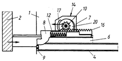
図1および2に示した実施例においてピニオン10を備えた回転式ダンパ20はケーシング7のみぞ穴13に変位式に支持されている。
【0022】
みぞ穴13は抽斗の前板2の方向に向かって斜め上方に傾けられており、これにより緩衝作動時に回転式ダンパ20に作用する力が合成されることとなる。従って回転式ダンパ20は十分な力で保持具17に押し付けられる。
【0023】
抽斗2が閉じられる場合には、スライダ8のストッパ9が本体側ストッパ11に当接した後、前述したようにケーシング7とスライダ8との間に相対運動が生ずることとなる。この相対運動により回転式ダンパ20は保持具17に押し付けられ、これにより回転式ダンパ20のケーシングは保持具17によってケーシング内に回転阻止されて保持される。すなわちピニオン10は回転式ダンパ20のケーシング内にある回転ピストンを回転させ、緩衝装置14が作動する。
【0024】
反対に抽斗2が開けられる場合には、回転式ダンパ20は図2に示したようにみぞ穴13内を下方に滑り落ち、従ってケーシング7に対して相対的に後方に移動する。従って回転式ダンパ20のケーシングは保持具17から離間させられ、回転式ダンパ20はスライダ8とピニオン10との間の相対運動に際してケーシングと共に全体として回転させられる。緩衝作用もしくは制動作用は生じない。
【0025】
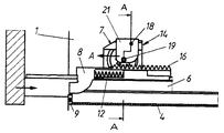
図3乃至10に示した実施例において回転式ダンパ20はロッカ21によってケーシング7に支持されている。ロッカ21は軸18を中心にして揺動することができる。ロッカ21がケーシング7に支持されている軸18は回転式ダンパ20がピニオン10と共にロッカ21に支持されている軸19に比して家具奥行き方向にずらされている。
【0026】
従って無負荷状態ではロッカ21は回転式ダンパ20と共に図4に示したポジションを占めており、換言すれば回転式ダンパ20は保持具17から離間した位置にある。ただし抽斗2を閉じる際にスライダ8のストッパ9が家具本体側ストッパ11に当接すると直ちに再びスライダ8とケーシング7との間に相対運動が生じ、ロッカ21は回転式ダンパ20と共に図3の矢印Aの方向に向かって保持具17に押し付けられ、これによって回転式ダンパ20のケーシングは回転阻止状態に保持され、回転式ダンパ20の緩衝作用が生ずることとなる。回転式ダンパ20はロッカ21の運動時にスライダ8の運動方向とほぼ平行に運動させられる。
【0027】
図3乃至5に示した実施例において保持具17は回転式ダンパ20のケーシングを摩擦接触によって回転阻止保持するゴム部品またはプラスチック部品である。
【0028】
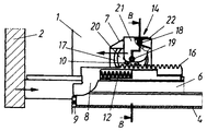
図6および7に示した実施例において保持具17と回転式ダンパ20のケーシング7とは爪歯23を有している。緩衝装置14の機能は前記の実施例と同じである。回転式ダンパ20のケーシングは保持具17により摩擦接触に代えて爪歯23によって回転阻止保持される。
【0029】
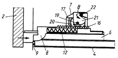
図8乃至10に示した実施例においてケーシング7には曲がりばねとして形成されたばね22が設けられており、該ばねはロッカ21を図9の矢印Bの方向に負荷している。すなわちロッカ21は、スライダ8からピニオン10に圧力が及ぼされないかまたはわずかに及ぼされるにすぎないかぎり、ばね22によって矢印Bの方向に押され、回転式ダンパ20のケーシングは確実に保持具17から離間させられ、その結果、抽斗は緩衝装置14によって妨げられずに閉ポジションに達することができる。
【0030】
前記のすべての実施例に共通している点は回転式ダンパ20のピニオン10と作動部品のラックとが常に互いに噛合っていることである。
【0031】
本発明による引出しガイドは、例えば欧州特許明細書EP 0 391 221 B1に記載されている類の抽斗引込み装置を備えているのが好ましい。その際、抽斗引込み装置のばねは抽斗2が確実に閉められるように引張りばね12よりも強力でなければならない。
【図面の簡単な説明】
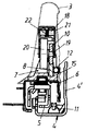
【図1】 本発明による緩衝装置を備えた引出しガイドの抽斗閉動作中の側面図である。
【図2】 抽斗開動作中の図1と同じ側面図である。
【図3】 本発明による別途実施例の緩衝装置を備えた引出しガイドの抽斗閉動作中の側面図である。
【図4】 抽斗開動作中の図3と同じ側面図である。
【図5】 図3の線A−Aで切断した断面図である。
【図6】 本発明による別途実施例の緩衝装置を備えた引出しガイドの抽斗閉動作中の側面図である。
【図7】 抽斗開動作中の図6と同じ側面図である。
【図8】 本発明による別途実施例の緩衝装置を備えた引出しガイドの抽斗閉動作中の側面図である。
【図9】 抽斗開動作中の図8と同じ側面図である。
【図10】 図8の線B−Bで切断した断面図である。
【符号の説明】
3・・・抽斗側板
4・・・家具本体側支えレール
6・・・引出しレール
7・・・ケーシング
8・・・スライダ
10・・・ピニオン
13・・みぞ穴
17・・・保持具
19・・・支持軸
20・・・回転式ダンパ
21・・・ロッカ
22・・・ばね
23・・・爪歯[0001]
[Technical field to which the invention belongs]
The present invention relates to a shock absorber for furniture movable parts.
[0002]
[Prior art]
2. Description of the Related Art Conventionally, a liquid damper is formed as a rotary damper that is composed of two parts that can rotate relative to each other, that is, a casing and a cylinder disposed in the casing, and is supported so as to be displaceable in the radial direction. A cushioning device for furniture moving parts, comprising: a cylinder filled with a buffer solution, for example silicone oil, and one of the two parts is rotated by the actuating part during the buffering operation, and the other part There is a shock absorber that is held against rotation.
[0003]
This type of shock absorber is used in modern furniture to prevent the door or drawer front plate from hitting the furniture body too hard when closing the furniture door or drawer.
[0004]
This type of shock absorber is preferably provided with a free wheel so that the shock absorber can reach the standby position without any difficulty when opening the door or drawer.
[0005]
[Problems to be solved by the invention]
The object of the invention is to provide an improved structurally simple freewheel in a shock absorber of the kind mentioned at the outset.
[0006]
[Means for Solving the Problems]
The object of the present invention is solved by the rotary damper being pressed against the holder by the operating part during the buffering operation.
[0007]
It is preferable that the cylinder is formed as a rotating body that is rotated by an operating component during a buffering operation, and the casing is held by being prevented from rotating by a holder.
[0008]
It is preferred that the parts that are prevented from rotating are held against rotation by frictional contact or claw teeth.
[0009]
In the preferred embodiment of the present invention, the rotary damper is pivotally supported by a rocker attached to the casing .
[0010]
In another embodiment of the invention, the rotary damper is supported by a support shaft in at least one, preferably two, oppositely facing slots provided in the casing .
[0011]
A further preferred embodiment of the invention is to prevent the action of the retracting device from being offset by the buffering action of the shock absorber when the door or drawer is closed very slowly, thus preventing the door or drawer from being completely closed. In FIG. 2, a rotary damper or a spring that separates the rotary damper component that is prevented from rotating during the buffering operation from the holder is provided.
[0012]
【Example】
Hereinafter, various embodiments of the present invention will be described with reference to the drawings.
[0013]
In the furniture body having the
[0014]
The drawer has one
[0015]
A
[0016]
The
[0017]
The
[0018]
When the drawer is opened, the
[0019]
When the
[0020]
A
[0021]
In the embodiment shown in FIGS. 1 and 2, the
[0022]
The
[0023]
When the
[0024]
When the
[0025]
In the embodiment shown in FIGS. 3 to 10, the
[0026]
Therefore, in the no-load state, the
[0027]
3 to 5, the
[0028]
In the embodiment shown in FIGS. 6 and 7, the
[0029]
In the embodiment shown in FIGS. 8 to 10, the
[0030]
The point common to all the above-mentioned embodiments is that the
[0031]
The drawer guide according to the invention preferably comprises a drawer drawing device of the kind described, for example, in the European patent specification EP 0 391 221 B1. In doing so, the spring of the drawer retractor must be stronger than the
[Brief description of the drawings]
FIG. 1 is a side view of a drawer guide equipped with a shock absorber according to the present invention during a drawer closing operation.
FIG. 2 is the same side view as FIG. 1 during the drawer opening operation.
FIG. 3 is a side view of the drawer guide equipped with the shock absorber according to another embodiment of the present invention during the drawer closing operation.
FIG. 4 is the same side view as FIG. 3 during the drawer opening operation.
5 is a cross-sectional view taken along line AA in FIG.
FIG. 6 is a side view of the drawer guide provided with the shock absorber according to another embodiment of the present invention during the drawer closing operation.
FIG. 7 is the same side view as FIG. 6 during the drawer opening operation.
FIG. 8 is a side view of the drawer guide equipped with the shock absorber according to another embodiment of the present invention during the drawer closing operation.
FIG. 9 is the same side view as FIG. 8 during the drawer opening operation.
10 is a cross-sectional view taken along line BB in FIG. 8. FIG.
[Explanation of symbols]
3 ...
Claims (22)
ケーシング(7)に対して放射状に変位し得るように支持された回転式液体ダンパ(20)であって、前記ケーシング(7)と、該ケーシング(7)内に配置された円筒とを含んでおり、
該ケーシング(7)と該円筒とは相対的に回転移動できるようになっている回転式液体ダンパ(20)と、
前記ケーシング(7)内に提供された緩衝液と、
を含んでおり、第1方向の移動による緩衝時に、前記円筒と前記ケーシング(7)の一方は作動部品によって回転され、他方は保持具(17)に押し付けられることで回転阻止されて保持され、
前記第1方向とは正反対の第2方向の移動では前記ケーシング(7)が前記円筒と共に回転することで緩衝作用は発生しないことを特徴とする緩衝装置(14)。A shock absorber (14) for a movable furniture member,
A casing (7) is supported so as to be displaceable radially relative to the rotary fluid damper (20), said casing (7), and a cylinder disposed the casing (7) in And
A rotary liquid damper (20) adapted to be relatively rotatable between the casing (7) and the cylinder;
A buffer provided in the casing (7);
One of the cylinder and the casing (7) is rotated by the actuating part and the other is pressed against the holder (17) to be held against rotation when buffering by movement in the first direction,
The shock absorber (14) is characterized in that in the movement in the second direction opposite to the first direction, the casing (7) rotates together with the cylinder so that no buffer action is generated.
Applications Claiming Priority (2)
| Application Number | Priority Date | Filing Date | Title |
|---|---|---|---|
| AT117/2001 | 2001-01-25 | ||
| AT0011701A AT412183B (en) | 2001-01-25 | 2001-01-25 | DAMPING DEVICE FOR MOVABLE FURNITURE PARTS |
Publications (2)
| Publication Number | Publication Date |
|---|---|
| JP2002242978A JP2002242978A (en) | 2002-08-28 |
| JP4135060B2 true JP4135060B2 (en) | 2008-08-20 |
Family
ID=3630318
Family Applications (1)
| Application Number | Title | Priority Date | Filing Date |
|---|---|---|---|
| JP2001391417A Expired - Lifetime JP4135060B2 (en) | 2001-01-25 | 2001-12-25 | Shock absorber for furniture moving parts |
Country Status (8)
| Country | Link |
|---|---|
| US (1) | US6666306B2 (en) |
| JP (1) | JP4135060B2 (en) |
| CN (1) | CN1221745C (en) |
| AT (1) | AT412183B (en) |
| BR (1) | BR0200181B1 (en) |
| DE (2) | DE20122622U1 (en) |
| ES (1) | ES2206002B1 (en) |
| IT (1) | ITMI20012668A1 (en) |
Cited By (1)
| Publication number | Priority date | Publication date | Assignee | Title |
|---|---|---|---|---|
| KR20150130880A (en) * | 2014-05-14 | 2015-11-24 | 최지한 | The Rotary damper module and Guide rail provided with a rotary damper module |
Families Citing this family (67)
| Publication number | Priority date | Publication date | Assignee | Title |
|---|---|---|---|---|
| US20060082266A1 (en) * | 2000-05-01 | 2006-04-20 | Le Hai D | Self-moving slides and self-moving mechanisms |
| DE10210917C1 (en) * | 2002-03-13 | 2003-11-13 | Itw Automotive Prod Gmbh & Co | Braking device with freewheel |
| US6848759B2 (en) * | 2002-04-03 | 2005-02-01 | Illinois Tool Works Inc. | Self-closing slide mechanism with damping |
| US6910557B2 (en) * | 2003-01-29 | 2005-06-28 | Illinois Tool Works Inc. | Slide damper with spring assist |
| DE20302524U1 (en) * | 2003-02-17 | 2004-06-24 | Arturo Salice S.P.A., Novedrate | Device for damping the movement of moving furniture parts in their closing area |
| US20040205183A1 (en) * | 2003-03-10 | 2004-10-14 | Sandvine Incorporated | Method and system for avoiding tracking communication connection state until accepted |
| DE20306195U1 (en) * | 2003-04-17 | 2004-08-26 | Arturo Salice S.P.A., Novedrate | Damping device for movable furniture parts |
| GB2401161B (en) * | 2003-05-02 | 2006-09-06 | Titus Internat Ltd | Improvements in movement controls |
| CA2521444C (en) * | 2003-05-13 | 2008-07-08 | Grass America Inc. | Drawer closing mechanism |
| US7104691B2 (en) * | 2003-07-31 | 2006-09-12 | Accuride International, Inc. | Self-moving slide, mechanism for self-moving slide and method for self-moving a slide |
| GB0328262D0 (en) * | 2003-12-05 | 2004-01-07 | Titus Int Plc | Improvements in movement controls |
| WO2005068760A1 (en) * | 2004-01-13 | 2005-07-28 | K.K. Murakoshi Seikoh | Damping device |
| TWI231344B (en) * | 2004-02-24 | 2005-04-21 | Lushridge Inc | Fastening structure of buffering rod |
| US20060169960A1 (en) * | 2004-04-06 | 2006-08-03 | Shaohan Li | Safety buffer for guide rails |
| JP4446824B2 (en) * | 2004-07-21 | 2010-04-07 | 株式会社ニフコ | Slide assist device |
| JP4446825B2 (en) * | 2004-07-21 | 2010-04-07 | 株式会社ニフコ | Slide assist device |
| JP4446823B2 (en) * | 2004-07-21 | 2010-04-07 | 株式会社ニフコ | Sliding assist device |
| WO2006052525A2 (en) * | 2004-11-05 | 2006-05-18 | Accuride International, Inc. | Self-moving mechanism and slide incorporating the same |
| US7537296B2 (en) * | 2004-11-05 | 2009-05-26 | Accuride International, Inc. | Dampened movement mechanism and slide incorporating the same |
| MY139426A (en) * | 2005-02-21 | 2009-09-30 | Harn Marketing Sdn Bhd | Drawer guide rail assembly |
| JP4756577B2 (en) * | 2005-04-25 | 2011-08-24 | 株式会社ムラコシ精工 | Shock absorber |
| ITTO20050332A1 (en) * | 2005-05-17 | 2006-11-18 | Itw Ind Components Srl | IMPROVED DEVICE FOR AUTOMATIC DRAWING OF A DRAWER, IN PARTICULAR A DRAWER OF A APPLIANCE AS A WASHING MACHINE |
| FR2886969B1 (en) * | 2005-06-10 | 2008-12-19 | Airbus Sas | LUGGAGE TYPE BAGGAGE COMPARTMENT DOOR |
| US7744035B2 (en) * | 2005-06-10 | 2010-06-29 | Airbus | Door for compartment of the baggage-compartment type |
| US20080211366A1 (en) * | 2005-06-27 | 2008-09-04 | Brock Patty J | Compact multifunctional self-closing slide assembly |
| US7850369B2 (en) * | 2005-09-02 | 2010-12-14 | Jonathan Engineered Solutions | Drop-in ball bearing slide assembly |
| US8079450B2 (en) * | 2005-11-14 | 2011-12-20 | Illinois Tool Works Inc. | Viscous strand damper assembly |
| AT504671B1 (en) | 2007-01-11 | 2012-07-15 | Blum Gmbh Julius | DAMPER |
| US20080210385A1 (en) * | 2007-02-28 | 2008-09-04 | Quanex Corporation | Retractable screen assembly |
| DE202007012816U1 (en) * | 2007-09-13 | 2008-05-08 | Grass Gmbh | Device with a guide unit for guiding a relative to a body movable furniture drawer |
| DE202007015230U1 (en) * | 2007-11-02 | 2008-02-28 | Herbach, Burkhard | Drive arrangement of a movable furniture part |
| ITMI20072168A1 (en) * | 2007-11-14 | 2009-05-15 | Agostino Ferrari Spa | "CONTROLLED CLOSING SYSTEM FOR FURNITURE SLIDING ELEMENTS" |
| CN101952533B (en) * | 2008-01-17 | 2014-05-07 | 株式会社利富高 | Retraction mechanism |
| JP2009215799A (en) * | 2008-03-11 | 2009-09-24 | Shibutani:Kk | Pull-in device of sliding door |
| AT506903B1 (en) * | 2008-05-19 | 2013-09-15 | Blum Gmbh Julius | DAMPING DEVICE FOR FURNITURE OR FURNITURE FITTINGS |
| SI2218859T1 (en) * | 2009-02-13 | 2011-12-30 | Electrolux Home Prod Corp | Oven door opening and closing device |
| MY151706A (en) * | 2009-08-12 | 2014-06-30 | Harn Marketing Sdn Bhd | Drawer assembly |
| KR101145615B1 (en) | 2010-01-25 | 2012-05-10 | 김희일 | Damping device for automatic door |
| US8210623B2 (en) * | 2010-01-29 | 2012-07-03 | King Slide Works Co., Ltd. | Sliding assembly with damping device |
| AT510361B1 (en) * | 2010-08-23 | 2013-12-15 | Blum Gmbh Julius | EXTRACTION GUIDE FOR DRAWERS |
| AT510018B1 (en) * | 2010-11-23 | 2012-01-15 | Blum Gmbh Julius | DEVICE FOR ASSEMBLING A FUNCTION PART ON A RAIL OF A DRAWER EXTRACTOR |
| JP5836281B2 (en) * | 2010-11-24 | 2015-12-24 | 株式会社ニフコ | Damper device |
| EP2550902B1 (en) * | 2011-07-27 | 2014-07-02 | Electrolux Home Products Corporation N.V. | Water drawer and appliance comprising water tank |
| DE202011106896U1 (en) | 2011-10-19 | 2011-11-09 | ACE Stoßdämpfer GmbH | Rotary brake device and use of a rotary brake device in the automotive industry |
| TW201320927A (en) * | 2011-11-21 | 2013-06-01 | Chong-Yao Chen | Pulling synchronizing device and shaft-mounting unit thereof |
| DE102012100202A1 (en) | 2012-01-11 | 2013-07-11 | Druck- und Spritzgußwerk Hettich GmbH & Co. KG | pull-out guide |
| CN102551380B (en) * | 2012-01-17 | 2015-05-13 | 伍志勇 | Slide rail for drawer |
| TWI482917B (en) * | 2012-03-09 | 2015-05-01 | Univ Nat Taiwan | Vibration damper and a method for operating a vibration-damping system having the same |
| TWI482916B (en) * | 2012-03-20 | 2015-05-01 | Univ Nat Taiwan | A vibration damper and a method for operating the vibration damper |
| CN103335052B (en) * | 2013-07-02 | 2015-04-29 | 大连理工大学 | Driven viscous damper adjustable in damping force |
| DE202014101503U1 (en) * | 2014-03-31 | 2015-07-06 | Grass Gmbh & Co. Kg | Device for motion damping |
| GB201411062D0 (en) * | 2014-06-20 | 2014-08-06 | Lama D D Dekani | Improvements in movement control devices |
| JP6570337B2 (en) * | 2014-07-17 | 2019-09-04 | キヤノン株式会社 | Image forming apparatus and damper apparatus |
| US9605405B2 (en) * | 2014-07-28 | 2017-03-28 | Caterpillar Global Mining Llc | Snubber for machine |
| CN106763591A (en) * | 2016-12-05 | 2017-05-31 | 黎炜杰 | A kind of two-way ejection of rack-and-pinion and resetting-mechanism |
| CN106993901A (en) * | 2016-12-23 | 2017-08-01 | 广州冠松电力科技有限公司 | A kind of plug-type electric power drawout cubicle |
| US10138666B2 (en) * | 2017-03-26 | 2018-11-27 | Nan Juen International Co., Ltd. | Anti-fall flip-up sliding mechanism |
| EP3604850A4 (en) * | 2017-03-31 | 2020-12-23 | Nifco Inc. | One-way damper mechanism |
| DE102017208450A1 (en) * | 2017-05-18 | 2018-11-22 | Schock Metallwerk Gmbh | guiding device |
| AT520275B1 (en) * | 2017-07-27 | 2021-08-15 | Fulterer Ag & Co Kg | Pull-out guide |
| CN107685698B (en) * | 2017-08-24 | 2020-03-24 | 安徽江淮汽车集团股份有限公司 | Assembly structure of automobile diagnosis interface plug-in |
| DE112018005430T5 (en) * | 2017-11-10 | 2020-07-16 | Tok, Inc. | Hinge arm damping mechanism |
| CN108374859B (en) * | 2018-02-08 | 2020-11-17 | 江苏三尔汽车部件有限公司 | Shock absorber |
| DE102018104398A1 (en) | 2018-02-27 | 2019-08-29 | Paul Hettich Gmbh & Co. Kg | Furniture or household appliance and method for mounting a functional unit of a push element in a piece of furniture or household appliance |
| CN111380317B (en) * | 2018-12-28 | 2022-01-21 | 海尔智家股份有限公司 | Linked rack and refrigerator using same |
| CN110979191B (en) * | 2019-12-05 | 2021-05-11 | 东风汽车集团有限公司 | Storage structure for vehicle |
| CN112576670B (en) * | 2020-12-04 | 2024-04-19 | 江苏科技大学 | Rotatable reduction friction composite metal damper |
Family Cites Families (15)
| Publication number | Priority date | Publication date | Assignee | Title |
|---|---|---|---|---|
| US4494806A (en) * | 1983-05-13 | 1985-01-22 | Leslie Metal Arts Company | Spring loaded drawer assembly with mechanical damping |
| JPH0610393B2 (en) * | 1984-09-26 | 1994-02-09 | 株式会社ニフコ | Drawer drawer device |
| JPH0742999B2 (en) * | 1986-08-05 | 1995-05-15 | 株式会社ニフコ | Oil type damper |
| US4872239A (en) * | 1988-08-10 | 1989-10-10 | The Chamberlain Group, Inc. | Door closure with mechanical braking means |
| AT393948B (en) * | 1989-04-03 | 1992-01-10 | Blum Gmbh Julius | LOCKING DEVICE FOR DRAWERS |
| DE4135216A1 (en) * | 1991-10-25 | 1993-04-29 | Fischer Artur Werke Gmbh | DAMPING ELEMENT FOR DAMPING A PUSH MOVEMENT |
| DE19532863A1 (en) * | 1994-09-09 | 1996-03-14 | Marcus Kracht | Automatic height=equalisation system for supporting surfaces on furniture |
| DE19618834A1 (en) * | 1995-05-26 | 1996-11-28 | Geze Gmbh & Co | Door closer with loadspring and damper |
| US5839548A (en) * | 1995-10-30 | 1998-11-24 | Illinois Tool Works Inc. | Motion control device for rotary dampers |
| US5690194A (en) * | 1995-10-30 | 1997-11-25 | Illinois Tool Works Inc. | One-way pivoting gear damper |
| DE29923738U1 (en) * | 1999-03-05 | 2001-03-01 | Bulthaup Gmbh & Co | Device for braking the closing movement of a drawer |
| DE29916841U1 (en) * | 1999-09-24 | 1999-12-30 | Huelsta Werke Huels Kg | Guide fitting for furniture, with self-closing |
| AT410506B (en) * | 2000-01-14 | 2003-05-26 | Blum Gmbh Julius | EXTENSION GUIDE SET FOR DRAWERS |
| AT410504B (en) * | 2000-01-14 | 2003-05-26 | Blum Gmbh Julius | LOCKING AND / OR PULL-IN DEVICE FOR MOVABLE FURNITURE PARTS |
| DE50102368D1 (en) * | 2000-01-14 | 2004-07-01 | Blum Gmbh Julius | Pull-out guide set for drawers |
-
2001
- 2001-01-25 AT AT0011701A patent/AT412183B/en not_active IP Right Cessation
- 2001-11-24 DE DE20122622U patent/DE20122622U1/en not_active Expired - Lifetime
- 2001-11-24 DE DE10163021A patent/DE10163021B4/en not_active Expired - Fee Related
- 2001-12-18 IT IT2001MI002668A patent/ITMI20012668A1/en unknown
- 2001-12-25 JP JP2001391417A patent/JP4135060B2/en not_active Expired - Lifetime
- 2001-12-26 ES ES200102882A patent/ES2206002B1/en not_active Expired - Fee Related
-
2002
- 2002-01-10 US US10/041,568 patent/US6666306B2/en not_active Expired - Lifetime
- 2002-01-24 CN CNB021027226A patent/CN1221745C/en not_active Expired - Fee Related
- 2002-01-24 BR BRPI0200181-0A patent/BR0200181B1/en not_active IP Right Cessation
Cited By (1)
| Publication number | Priority date | Publication date | Assignee | Title |
|---|---|---|---|---|
| KR20150130880A (en) * | 2014-05-14 | 2015-11-24 | 최지한 | The Rotary damper module and Guide rail provided with a rotary damper module |
Also Published As
| Publication number | Publication date |
|---|---|
| BR0200181A (en) | 2002-10-22 |
| US20020096405A1 (en) | 2002-07-25 |
| ES2206002B1 (en) | 2006-02-16 |
| JP2002242978A (en) | 2002-08-28 |
| DE10163021B4 (en) | 2013-11-14 |
| ES2206002A1 (en) | 2004-05-01 |
| BR0200181B1 (en) | 2010-07-13 |
| ITMI20012668A1 (en) | 2003-06-18 |
| CN1367327A (en) | 2002-09-04 |
| CN1221745C (en) | 2005-10-05 |
| DE10163021A1 (en) | 2002-11-07 |
| US6666306B2 (en) | 2003-12-23 |
| DE20122622U1 (en) | 2006-08-17 |
| AT412183B (en) | 2004-11-25 |
| ATA1172001A (en) | 2004-04-15 |
Similar Documents
| Publication | Publication Date | Title |
|---|---|---|
| JP4135060B2 (en) | Shock absorber for furniture moving parts | |
| AU2009250315B2 (en) | Damping device for furniture components or furniture fitting components | |
| JP6209269B2 (en) | Drive unit for movable furniture | |
| JP3709153B2 (en) | Deceleration closure device for furniture slide | |
| JP7307752B2 (en) | Deceleration hinge for furniture | |
| US20130145580A1 (en) | Damping device for furniture parts | |
| JP6709790B2 (en) | Slowdown hinges for furniture | |
| WO2005068760A1 (en) | Damping device | |
| JP2013500410A (en) | A pivotally supported door with hinges | |
| JP2017515018A (en) | Furniture flap door drive | |
| JP2002138746A (en) | Hinge | |
| KR20170007319A (en) | Hinge | |
| CN110832162B (en) | Flap fitting and furniture item | |
| TW201116230A (en) | Decelerated hinge structure for a furniture, with a foldable shelf | |
| KR102519464B1 (en) | Damper assembly and flap fitting | |
| JP6258489B2 (en) | Furniture drive | |
| KR101276670B1 (en) | Hinge device for furniture | |
| JP2004332307A (en) | Soft closer mechanism | |
| CN216043262U (en) | Door body shutter with buffer device | |
| JPH07331952A (en) | Shock absorber of door, etc. | |
| WO2018121720A1 (en) | Damper, and laundry machine using same | |
| JPH0960678A (en) | Damper of fluid frictional resistance type | |
| WO2022248195A1 (en) | Damping device for pieces of furniture | |
| WO2018121721A1 (en) | Damper, and laundry machine using same | |
| WO2023027672A1 (en) | A deceleration mechanism for household appliances or hinges |
Legal Events
| Date | Code | Title | Description |
|---|---|---|---|
| A621 | Written request for application examination |
Free format text: JAPANESE INTERMEDIATE CODE: A621 Effective date: 20041213 |
|
| A977 | Report on retrieval |
Free format text: JAPANESE INTERMEDIATE CODE: A971007 Effective date: 20060914 |
|
| A131 | Notification of reasons for refusal |
Free format text: JAPANESE INTERMEDIATE CODE: A131 Effective date: 20060919 |
|
| A521 | Request for written amendment filed |
Free format text: JAPANESE INTERMEDIATE CODE: A523 Effective date: 20061215 |
|
| A131 | Notification of reasons for refusal |
Free format text: JAPANESE INTERMEDIATE CODE: A131 Effective date: 20070702 |
|
| A601 | Written request for extension of time |
Free format text: JAPANESE INTERMEDIATE CODE: A601 Effective date: 20070928 |
|
| RD02 | Notification of acceptance of power of attorney |
Free format text: JAPANESE INTERMEDIATE CODE: A7422 Effective date: 20070928 |
|
| A602 | Written permission of extension of time |
Free format text: JAPANESE INTERMEDIATE CODE: A602 Effective date: 20071012 |
|
| A521 | Request for written amendment filed |
Free format text: JAPANESE INTERMEDIATE CODE: A523 Effective date: 20071031 |
|
| TRDD | Decision of grant or rejection written | ||
| A01 | Written decision to grant a patent or to grant a registration (utility model) |
Free format text: JAPANESE INTERMEDIATE CODE: A01 Effective date: 20080422 |
|
| A01 | Written decision to grant a patent or to grant a registration (utility model) |
Free format text: JAPANESE INTERMEDIATE CODE: A01 |
|
| A61 | First payment of annual fees (during grant procedure) |
Free format text: JAPANESE INTERMEDIATE CODE: A61 Effective date: 20080521 |
|
| R150 | Certificate of patent or registration of utility model |
Ref document number: 4135060 Country of ref document: JP Free format text: JAPANESE INTERMEDIATE CODE: R150 |
|
| FPAY | Renewal fee payment (event date is renewal date of database) |
Free format text: PAYMENT UNTIL: 20110613 Year of fee payment: 3 |
|
| FPAY | Renewal fee payment (event date is renewal date of database) |
Free format text: PAYMENT UNTIL: 20120613 Year of fee payment: 4 |
|
| R250 | Receipt of annual fees |
Free format text: JAPANESE INTERMEDIATE CODE: R250 |
|
| FPAY | Renewal fee payment (event date is renewal date of database) |
Free format text: PAYMENT UNTIL: 20130613 Year of fee payment: 5 |
|
| R250 | Receipt of annual fees |
Free format text: JAPANESE INTERMEDIATE CODE: R250 |
|
| R250 | Receipt of annual fees |
Free format text: JAPANESE INTERMEDIATE CODE: R250 |
|
| R250 | Receipt of annual fees |
Free format text: JAPANESE INTERMEDIATE CODE: R250 |
|
| R250 | Receipt of annual fees |
Free format text: JAPANESE INTERMEDIATE CODE: R250 |
|
| R250 | Receipt of annual fees |
Free format text: JAPANESE INTERMEDIATE CODE: R250 |
|
| R250 | Receipt of annual fees |
Free format text: JAPANESE INTERMEDIATE CODE: R250 |
|
| R250 | Receipt of annual fees |
Free format text: JAPANESE INTERMEDIATE CODE: R250 |
|
| R250 | Receipt of annual fees |
Free format text: JAPANESE INTERMEDIATE CODE: R250 |
|
| R250 | Receipt of annual fees |
Free format text: JAPANESE INTERMEDIATE CODE: R250 |
|
| R250 | Receipt of annual fees |
Free format text: JAPANESE INTERMEDIATE CODE: R250 |
|
| EXPY | Cancellation because of completion of term |