JP4134792B2 - Eccentric thrust bearing - Google Patents
Eccentric thrust bearing Download PDFInfo
- Publication number
- JP4134792B2 JP4134792B2 JP2003100760A JP2003100760A JP4134792B2 JP 4134792 B2 JP4134792 B2 JP 4134792B2 JP 2003100760 A JP2003100760 A JP 2003100760A JP 2003100760 A JP2003100760 A JP 2003100760A JP 4134792 B2 JP4134792 B2 JP 4134792B2
- Authority
- JP
- Japan
- Prior art keywords
- races
- race
- case
- thrust bearing
- bearing
- Prior art date
- Legal status (The legal status is an assumption and is not a legal conclusion. Google has not performed a legal analysis and makes no representation as to the accuracy of the status listed.)
- Expired - Fee Related
Links
Images
Landscapes
- Rolling Contact Bearings (AREA)
- Support Of The Bearing (AREA)
Description
【0001】
【発明の属する技術分野】
本発明は、偏心スラスト軸受に関するものである。
【0002】
【従来の技術】
従来公然実施されている単列の偏心スラスト軸受は、2枚一対のレースと、これらのレース間に介在する転動体を有するものである。この軸受は、対向する2枚の板状レースの間に複数個の玉等の転動体を挟んだ構造とすることにより、2枚のレースは互いに径方向にずれて偏心するように動くことができ、かつ2枚のレース間で相対的に旋回転動することも可能となっている。
【0003】
【発明が解決しようとする課題】
かかる従来の単列偏心スラスト軸受では、一方向のアキシャル荷重、即ち転動体を圧縮する方向のアキシャル荷重は支持することができるが、両方向のアキシャル荷重を支持することができない。即ち、対向する2枚のレースを引き離す方向のアキシャル荷重を支持することができない。両方向のアキシャル荷重を支持できるようにするためには、転動体を複列(複式)とした複列スラスト軸受とする必要がある。しかし複列とした場合、軸受幅(軸受の軸方向幅)が大きくなってしまうという問題があった。
【0004】
本発明は、かかる事情に鑑みてなされたものであって、複列構造よりも軸受幅を小さくしながら、両方向のアキシャル荷重を支持できる偏心スラスト軸受を提供することを目的とする。
【0005】
【課題を解決するための手段】
かかる目的を達成するため、本発明では、第一の外側部材及びその径方向内側に位置する第一の内側部材が設けられるとともに、これらに対向して第二の外側部材及びその径方向内側に位置する第二の内側部材が設けられ、周方向に沿った3カ所以上に局在する第一位置において対向した前記第一の外側部材と前記第二の内側部材とで、前記第一位置に配置された転動体を挟持するとともに、周方向に沿った3カ所以上に局在し前記第一位置とは位相が異なる第二位置において対向した前記第二の外側部材と前記第一の内側部材とで、前記第二位置に配置された転動体を挟持し、前記第一の外側部材と前記第一の内側部材とは、相互間に隙間を設けて径方向及び周方向への相対移動を可能とし、且つ前記第二の外側部材と前記第二の内側部材とは、相互間に隙間を設けて径方向及び周方向への相対移動を可能とし、前記第一の外側部材と前記第二の外側部材とが一体的に接合されるとともに、前記第一の内側部材と前記第二の内側部材とが一体的に接合されており、全ての前記転動体の中心は同一平面上に存在することを特徴とする偏心スラスト軸受としている。
【0006】
このようにすると、従来複列としていた偏心スラスト軸受の各部材に対応する部材を互い違いに配置することにより、従来複列であった各列相互間の軸方向距離を近接させることができ、複列の軸受よりも軸受幅を小さくすることができる。即ち、第一の外側部材と第二の内側部材及びこれらに挟持され周方向に沿った三カ所以上に局在した転動体が従来の複列軸受における第一列の偏心スラスト軸受部分(1)として機能し、第二の外側部材と第一の内側部材及びこれらに挟持され周方向に沿った三カ所以上に局在した転動体が第二列の偏心スラスト軸受部分(2)として機能することができる。本発明では外側部材同士、内側部材同士がそれぞれ相互に一体的に接合しているので、従来の複列偏心スラスト軸受部分(1)に相当する部分が一方向のアキシャル荷重を支持でき、偏心スラスト軸受部分(2)に相当する部分が他方向のアキシャル荷重を支持できる。また、第一位置と第二位置との位相を異ならせ、且つ外側部材と内側部材は両者間において可動平面方向で隙間があるので、各列の転動体の軸方向位置を近接させ、全ての転動体の中心は同一平面上に存在する構成を採ることができる。また、外側部材と内側部材とが互いに相対移動することができる。また、以上のような構成とすると、軸受の各部材が分離せず、組み立てられた軸受として供給することが可能となる。また、全ての前記転動体の中心は同一平面上に存在する構成とすることにより、軸受を単列構造とすることができ、軸受の軸方向幅を最小とすることができる。
【0007】
また、前記第一の外側部材は、局在する前記第一位置のそれぞれに分割して設けられた外レースと、これら全ての外レースが取付けられた第一の外側ケースから成り、前記第二の外側部材は、局在する前記第二位置のそれぞれに分割して設けられた外レースと、これら全ての外レースが取付けられた第二の外側ケースから成り、前記第一の内側部材は、局在する前記第二位置のそれぞれに分割して設けられた内レースと、これら全ての内レースが取付けられた第一の内側ケースから成り、前記第二の内側部材は、局在する前記第一位置のそれぞれに分割して設けられた内レースと、これら全ての内レースが取付けられた第二の内側ケースから成るとともに、前記転動体は前記外レースと前記内レースの間に挟持されている構成とするのが好ましい。この場合には、局在する転動体の各位置にそれぞれ別個のレースを分割して配しているので、個々のレースを小型化することができる。レースが大型化するとレース軌道面の平面度の精度を確保しにくくなるが、レースを小型化できることにより、軸受の大型化が容易となる。また、軸受用鋼等によりなるレース部分を減らし且つケース部分にはアルミ合金等の低比重金属や樹脂等を利用できるので、軸受全体の重量を軽量化できる。
【0008】
前記隙間により生ずる外側部材と内側部材との相対移動可能範囲が、転動体の移動可能範囲に略対応している構成としてもよい。このようにすると、外側部材と内側部材との間の隙間と、転動体の移動空間を確保するためレース上に設けられた隙間のいずれについても、余分な隙間を無くすか、あるいは最小限とすることができる。従って、軸受を小型化しながらその偏心可能範囲をより広くすることができる。
【0009】
さらに、前記偏心スラスト軸受は、次の構成としてもよい。即ち、前記第一位置及び第二位置はそれぞれNカ所(Nは3以上の整数)に等配されており、前記第一及び第二の外側ケースは同一形状であり、その形状は、軸受の外周を成す外周円環状部と、この外周円環状部から径方向内側に向かって且つ周方向に等間隔をおいて突出したN個の内向き舌片部とを有するものであり、前記第一及び第二の内側ケースは同一形状であり、その形状は、軸受の内周を成す内周円環状部と、この内周円環状部から径方向外側に向かって且つ周方向に等間隔をおいて突出したN個の外向き舌片部とを有するものであり、前記全ての外向き舌片部には前記内レースが同一円周上で取付けられ、前記全ての内向き舌片部には前記外レースが同一円周上で取付けられるとともに、前記内レース及び前記外レースは全て同一形状の円板状部材であり、前記第一位置と第二位置は、同一円周上に、且つ周方向に360/(2N)度ずつ位相をずらして交互に局在している構成としてもよい。
【0010】
このようにすると、転動体の第一位置と第二位置を周方向及び径方向に均等に配置できるので、両方向のアキシャル荷重をより安定的に支持でき、さらに偏心された軸からのアキシャル荷重によって生ずるモーメント荷重もより安定的に支持できる。さらに、各レースを同一とできるので、各レース部材を共通化できる。
【0011】
前記各レースの周囲を包囲する第一保持器ガイドを有する構成としてもよい。このようにすると、転動体の位置調整が容易となる。即ち、転動体の位置をレース上の最適位置に調整するのは容易ではないが、軽予圧をかけた状態で軸受を全ての径方向及び周方向について最大に相対移動させることにより、位置ズレした転動体は第一保持器ガイドに係止されレース上を適宜滑りつつ位置調整がなされる。よって、転動体をレース上の最適な位置に配置することが容易となる。また、この第一保持器ガイドにより、対向するレース間への異物の侵入や潤滑剤の流出を抑制できる。
【0012】
さらに全ての前記転動体間の相対的位置関係を維持する単一の第二保持器ガイドを有する構成としてもよい。このようにすると、転動体に偏荷重が作用した場合でも転動体が移動して位置ズレを起こすことがない。
【0013】
【発明の実施の形態】
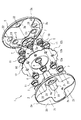
以下、本発明の実施形態を図面に基づいて説明する。図1は、本発明の一実施形態である偏心スラスト軸受1の構成を示す分解斜視図、図2はこの軸受1の、玉8の中心位置を通る軸方向断面(中心から外周までの半断面)の断面図である。この図2の断面の周方向位置は、第一の外側ケース2の内向き舌片部2bの中心位置としている。なお図2は玉8がいずれの方向にも移動していない状態(以下、標準状態ともいう)を示す。図1に示すように、この軸受1の外周等を構成する外側部材は、第一の外側部材と第二の外側部材により構成される。第一の外側部材は、第一の外側ケース2と、これに取付けられた円板状の外レース6からなる。第二の外側部材は、第二の外側ケース3と、これに取付けられた円板状の外レース6からなる。第一の外側ケース2は、軸受1の外周を成す外周円環状部2aと、この外周円環状部2aから径方向内側に向かってかつ周方向に90度おきに等間隔をおいて突出した4個の内向き舌片部2bを有する。第二の外側ケース3は、第一の外側ケース2と同一形状であって、同じく外周円環状部3aと4個の内向き舌片部3bを有する。これら第一の外側ケース2と第二の外側ケース3は周方向に45度だけ位相をずらした状態で対向している。したがって、互いの舌片部2bと3bは対向することなく互い違いの周方向位置に45度おきに配置される。
【0014】
この軸受1の内周等を構成する内側部材は、第一の内側部材と第二の内側部材からなる。第一の内側部材は、第一の内側ケース4と、これに取付けられた円板状の内レース7からなる。第二の内側部材は、第二の内側ケース5と、これに取付けられた円板状の内レース7からなる。第一の外側ケース2の径方向内側に位置し、この軸受1の内周等を構成する第一の内側ケース4は、軸受1の内周を成す内周円環状部4aと、この内周円環状部4aから径方向外側に向かってかつ周方向に90度おきに等間隔をおいて突出した4個の外向き舌片部4bを有する。また、第二の外側ケース3の径方向内側に設けられた第二の内側ケース5は第一の内側ケース4と同一形状であって、同様に内周円環状部5aと4個の外向き舌片部5bを有する。これら第一の内側ケース4と第二の内側ケース5は周方向に45度だけ相対的に相違した状態で対向している。したがって、互いの舌片部4bと5bは対向することなく互い違いの周方向位置に45度おきに配置される。
【0015】
第一の外側ケース2の4個の内向き舌片部2bと第二の内側ケース5の4個の外向き舌片部5bとは、位相が同一の第一位置21で互いに対向している。また、第二の外側ケース3の4個の内向き舌片部3bと第一の内側ケース4の4個の外向き舌片部4bとは位相が同一の第二位置22で互いに対向している。また、全ての内向き舌片部2b及び3bの各対向面には円板状の外レース6が舌片部1個につき1枚(合計8枚)設けられている。同様に、全ての外向き舌片部4b及び5bの対向面には、外レース6と同一形状の円板状の内レース7が舌片部1個につき1枚(合計8枚)設けられている。そして、外レース6と内レース7の間には転動体である玉8が各レース間に一個ずつ、合計8個介在している。これら全ての玉8はその中心が同一平面上に配置されており、本実施形態は単列の偏心スラスト軸受となっている。
【0016】
図1及び図2に示すように、各玉はそれぞれ別個に円筒状の保持器10に挿入されている。また、外レース6及び内レース7の全てにおいて、その周囲にはリング状の第一保持器ガイド11が外嵌して、内外レース6,7を包囲している。(図2参照)。この第一保持器ガイド11は、各内外レース6,7に外嵌しつつレース軌道面よりも転動体側に突出している。よって、第一保持器ガイド11の内周面は、各内外レース6,7の周囲にレース軌道面と垂直な壁面を構成する。さらに、その中心が同一平面上に配置された全ての玉8を保持する全ての保持器10間の相対的位置関係は、略ドーナツ型の円板である一枚の第二保持器ガイド12によって維持されている。この第二保持器ガイド12には、周方向の45度おきに合計8カ所の保持器挿入孔12aが設けられている。この保持器挿入孔12aに円筒状の保持器10が内嵌している(図2参照)。これら第二保持器ガイド12及び保持器10によって、全ての玉8が等間隔に保持されている。軸受1にモーメント荷重がかかる場合等においては、転動体に偏荷重が作用することがあり、この偏荷重により一部の玉8がレースから浮いた場合等には、この一部の玉8が移動してしまうことが考えられる。しかしこの場合でも、第二保持器ガイド12により、一部の玉8が移動して位置ズレを起こすことがない。なお、第二保持器ガイド12の外周縁部に周方向等間隔をおいて円弧状の凹部12cがあるが、これは2つの外側ケースを連結するねじ15部分に対する逃げである。
【0017】
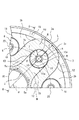
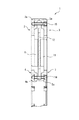
図3は、図2のA−A断面位置から第二保持器ガイド12を除いて矢印方向に軸受1内部をみた要部正面図(1/4周分のみ記載)である。この図3も標準状態であり、また第二保持器ガイド12は仮想線で示してある。図4は、図3のB−B位置の断面におけるこの軸受1の標準状態における断面図である。図2〜図4に示すように、第一の外側ケース2の径方向内側には第一の内側ケース4が設けられ、互いの軸方向位置は略同一である。同様に、第二の外側ケース3の径方向内側には第二の内側ケース5が設けられ、互いの軸方向位置は略同一である。また、図4に示すように、第一の外側ケース2と第二の外側ケース3は、これらの外周円環状部2a及び3aの近傍において、ねじ15により一体的に接合されている。また、第一の内側ケース4と第二の内側ケース5は、これらの内周円環状部4a及び5aの近傍において、ねじ16により一体的に接合されている。これらのねじ15及び16は、それぞれ周方向に均等な位置に複数設けられている。なお図1では、このねじ15及び16部分の記載を省略している。
【0018】
図1に示すように、第一の外側ケース2の内向き舌片部2bに取付けられた4つの外レース6と、これらに対向する4つの内レース7(第二の内側ケース5の外向き舌片部5bに取付けられた4つの内レース7)の周方向配置位置は4カ所に局在する第一位置21である。また、第二の外側ケース3の内向き舌片部3bに取付けられた4つの外レース6と、これらに対向する4つの内レース7(第一の内側ケース4の外向き舌片部4bに取付けられた4つの内レース7)の周方向配置位置は4カ所に局在する第二位置22である。これら第一位置21と第二位置22及び各レースは、図3に示すように、同一円周上23に、且つ互いに周方向の相違角度αを45度として、この角度αずつ位相をずらして交互に配置されている。
【0019】
このように、第一位置21と第二位置22の位置を相互に異ならせることにより、従来複列であった軸受の2列の玉8の各列間の軸方向距離をより近接させることができ、全ての玉8について、それぞれの中心部が同一平面上に存在する構成を採ることができるので、単列化が可能となる。しかも、複列構造とせずに両方向のアキシャル荷重を支持することが可能となる。即ちこのようにすると、従来複列としていた偏心スラスト軸受の各部材に対応する部材を周方向で互い違いに配置することとなり、単列化することもできる。つまり、第一の外側ケース2と第二の内側ケース5及びこれらの間に介在する内外レース7,6と玉8が、従来の複列軸受における第一列の偏心スラスト軸受部分(1)として機能し、第二の外側ケース3と第一の内側ケース4及びこれらの間に介在する内外レース7,6と玉8が、従来の複列軸受における第二列の偏心スラスト軸受部分(2)として機能することができる。外側ケース2,3同士及び内側ケース4,5同士がそれぞれ相互に一体的に接合しているので、従来の複列偏心スラスト軸受部分(1)に相当する部分が一方向のアキシャル荷重を支持でき、偏心スラスト軸受部分(2)に相当する部分が他方向のアキシャル荷重を支持できる。また、このように単列構造としたことにより、複列とした場合と比較して軸受幅を小さくすることができる。なお、本発明の偏心スラスト軸受は、その偏心可能範囲内において周方向及び径方向に移動が可能であるので、この移動可能範囲内で相対的に回転することもできるが、この範囲を超えた回転(所定角度以上の相対回転)はできない。
【0020】
そして、円板状部材の各外レース6及び各内レース7が第一位置21及び第二位置22の各局在位置にそれぞれ配置されている。なお図2に示すように、各レース6,7にはその周縁に段差9を設けることにより軸方向外側面を凸部とする一方、各舌片部にはこの凸部に対応する凹部を設け、これら凹凸を組み合わせることにより各レース6,7と各舌片部2b,3b,4b,5bとが組合わされている。
【0021】
図2及び図3に示すように、第二の外側ケース3の内周面3cと、第二の内側ケース5の外周面5cとの間には、隙間K1(図3においてハッチングで表示)が全周に亘って設けられている。図3に示すように、隙間K1の幅は、外向き舌片部5bの径方向最外位置では径方向で距離Lであり、内向き舌片部3bの径方向最内位置では径方向で距離Mとなっている。また、この隙間K1の幅を全体に亘って略同一とすべく、第二の外側ケース3の内周面3cの輪郭形状は、第二の内側ケース5の外周面5cの輪郭形状を略倣う形状とされている。その結果、隙間K1の幅はその全体に亘ってL以上M以下となっている。また、距離Mは内側ケース4,5の強度確保にも留意して設定する。距離Mは距離Lと同一にするのが好ましい。この隙間K1があるので、第二の外側ケース3と第二の内側ケース5を軸線方向同一位置に配置して玉8を単列とすることができ、さらに、第二の内側ケース5と第二の外側ケース3は径方向全方位に略距離Lまでの相対移動が可能で且つ周方向にも互いに相対移動(相対回転)可能となる。第二の内側ケース5の外向き舌片部5bの先端部は半円形状となっているが(図3参照)、これは、内レース7の円形形状に対応させたものであり、且つ、第二の内側ケース5と第二の外側ケース3の間で、玉8の標準位置を中心とした周囲に距離略Lの相対的な移動ストロークを確保するためである。また、第二の外側ケース3の内向き舌片部3bの先端部も円弧状となっているが、これは外レース6の形状に対応させたものであり、且つ、第二の内側ケース5と第二の外側ケース3の間で、玉8の標準位置を中心とした周囲に距離略Lの相対的な移動ストロークを確保するためである。このように、隙間K1の範囲が、内側ケース5と外側ケース3との相対的移動可能範囲を決めている。
【0022】
転動体である玉8は、これを収容する保持器10の外周面10aと第一保持器ガイド11の内周面11aとの間に存在する、玉8を中心とした円環状の幅Rの隙間K2(図3参照)により移動が可能となっている。即ち、保持器10の外周面10aと第一保持器ガイド11の内周面11aとが接触するまで、玉8は移動することが可能である。本実施形態では、各レース6,7の面積(直径)、玉8及び保持器10の直径、第一保持器ガイド11の内径が玉8の移動可能範囲を決定している。このように、隙間K2の範囲が、玉8の移動可能範囲を決めている。
【0023】
本実施形態では、玉8を収容する保持器10の外周面10aと第一保持器ガイド11の内周面11aとの間の隙間距離R(標準状態における径方向の隙間距離R)は、前記隙間距離Lの半分となっている。即ち、次の数式、
L=2R
の関係が成立している。このようにしたのは、レースの相対移動距離に対して玉8の移動距離が半分であることに対応したものである。このように、距離Rが距離Lの半分となるように、内レース6及び外レース7の直径を設定している。
【0024】
このように、第二の内側ケース5と第二の外側ケース3との間の隙間K1により生ずるこれらケース間の相対的移動可能範囲と、保持器10の外周面10aと第一保持器ガイド11の内周面11aとの隙間K2により生ずる玉8の移動可能範囲とが略対応している。換言すれば、内外ケース5,3間の隙間K1により生ずる両者の相対的移動可能範囲が軸受1の偏心可能範囲に略一致している。つまり、玉8を収容する保持器10の外周面10aと第一保持器ガイド11の内周面11aとが当接するまで玉8が移動すると、同時に第二の内側ケース5と第二の外側ケース3が略当接することとなり、余分な隙間が最小限とされている。よって、軸受1を小型化しながら偏心可能範囲を最大限に広げることができる。
【0025】
玉8の周囲に余分な隙間を設けないということは、各レース6,7を余分に大きくしないことをも意味する。従って、小さいレース6,7で最大限の偏心可能範囲を確保することができる。なお、図2に示すように、第二保持器ガイド12の外周面と、2つの外側ケースの外周円環状部2a,3aの内周面との間の隙間距離Sは前記距離Rよりも若干大きくしており、軸受1の偏心可能範囲において互いに接触しないようになっている。
【0026】
更に、本実施形態では、全ての外レース6及び内レース7は同一径で同一形状の円板となっており、しかも、標準状態においてすべてのレースが同一円周上23(図3参照)に設けられている。そうすると、全ての局在位置、即ち全ての第一位置21及び第二位置22において、各玉8におけるそれぞれの移動可能範囲が、軸受1の偏心可能範囲と対応している。即ち、可動平面内の全方位について、軸受1を偏心可能範囲の限界まで移動させると、全ての玉8がそれぞれの移動可能範囲のほぼ限界まで移動するようになっている。即ち、全ての内外レース6,7を同一の部材で共通化でき且つそれらの大きさを最小限としている。
なお、ここでは第二の外側ケース3と第二の内側ケース5との関係を例として説明したが、第一の外側ケース2と第一の内側ケース4との関係も同様の構成である。
【0027】
玉8を、標準状態において図2のように外レース6及び内レース7の中心位置に配置するには、軸受1を組み立てた後、軸受1に軽予圧をかけた状態で全ての径方向及び周方向について最大に相対移動させればよい。このようにすると、位置ズレしている玉8を保持する保持器10が第一保持器ガイド11と接触して玉8がレース上で滑り、玉8の位置が標準状態で内外レース6,7の中心位置になるように調整される。このように、第一保持器ガイド11を設けることにより、玉8の位置調整が容易となり、特に軸受1が組み立てられた状態であっても玉8の位置調整を簡便に行うことが可能となっている。
【0028】
なお、軸受1がアセンブル部材として軸受1以外の他の装置に取付けられた場合であって、この装置において例えばゴムやバネ等を用いて軸受1の相対移動範囲を制約する手段があり、これにより制約される範囲が軸受1の偏心可能範囲より狭い範囲である場合には、軸受1はその構成部品間で干渉することがない。
【0029】
外レース6及び内レース7の形状は特に限定されないが、本実施形態では、これらのレース6,7は第一位置21及び第二位置22の各局在位置に分割して設けるレース分割構造としている。このようにすると、玉8が転がり接触する部分であって通常軸受用鋼等の鉄系材料で作製されるレース部分を少なくすることができるので、コストを低減することができる。また、これらのレース6,7を保持して各レースを一体的に連結する内側ケース4,5及び外側ケース2,3は、玉8と接触しないので、アルミ合金等の軽金属を用いることができる。したがって、このようなレース分割構造とした場合には、個々のレース6,7の大きさを小さくでき、軸受1の軽量化が可能となるので好ましい。また、一般に軸受が大型化されると、レース6,7も大型化される傾向にあるが、レースが大型化されるとレース軌道面の平面度を確保するための加工が極めて困難となる。本実施形態のようにレースを分割すると、個々のレースの大きさは小型化しつつ軸受全体の大型化が容易となる。
【0030】
ここで、前記第一位置21及び第二位置22はそれぞれ4カ所、つまり3カ所以上に局在しており、さらにこれら3カ所以上の位置は一直線上になく、周方向に沿っているので、玉8を介して対向する2組の内側ケース4,5と外側ケース2,3は、それぞれ3点以上で支持されることになる。したがって両方向のアキシャル荷重が支持可能になるとともに、モーメント荷重も支持可能となる。したがって、この第一位置21及び第二位置22は、本実施形態のようにそれぞれ4カ所に局在する場合に限られず、3カ所以上であればよい。好ましくは本実施形態のように、第一位置21及び第二位置22共に、これら3カ所以上の局在位置を周方向180度(半円)の範囲にすべて設けることのないように、周方向で180度を超える範囲に配置するのがよい。このようにすると対向する面の支持点が周方向により分散するので、大きなモーメント荷重を支持できるとともに、アキシャル荷重を面内により均等分散でき、各玉8にかかる負荷がより均等になるので好ましい。
【0031】
そして、本実施形態では、第一位置21と第二位置22の局在位置の数はそれぞれ同数のNカ所(Nは3以上の整数)とし、さらに、第一位置21と第二位置22は、同一円周23(図3参照)上に、且つ周方向に360/(2N)度ずつ位相をずらして交互に配置している。このようにすると、第一位置21と第二位置22が周方向及び径方向に均等に分散して局在することになるので、両方向のアキシャル荷重及びモーメント荷重を効率よく支持することができる。
【0032】
さらにこの場合、それぞれの玉8の移動範囲は同一となる。そうすると、全てのレース6,7の大きさを最小限とした同一形状のものにすることができ、軸受1をさらに軽量化することができる。なお、Nは3以上の整数であるのが良いが、多すぎると偏心可能範囲を確保するための部材間の隙間距離が狭くなると共に、部品点数が多くなり構造が複雑となる傾向となるので、通常はNを4〜6とするのが好ましい。モーメント負荷能力と偏心可能範囲のバランスからはNを5とするのがさらに好ましい。
【0033】
保持器10は本発明では必ずしも必要ではない。しかし、本実施形態のように、各玉8を収容する保持器10を用いると、玉8周辺に供給される潤滑油やグリース等の潤滑剤の流出を抑制できる。また、第一保持器ガイド11は、前述のように玉8の位置調整を容易にするが、保持器10と第一保持器ガイド11とを組み合わせて使用することによりこの位置調整がより確実となる。即ち、保持器10の外周面と第一保持器ガイド11の内周面とが当接することにより、位置調整の際により確実に玉8を滑らすことができる。また、第一保持器ガイド11により、各レース6,7の周囲にレース間への異物の侵入を抑制することが可能となり、軸受全体のシール部材としての機能をも有する。
【0034】
さらに、保持器10と第二保持器ガイド12の組み合わせにより、第二保持器ガイド12の厚みが比較的薄くても各玉8間の相対的位置関係を維持できる。即ち、保持器10が第二保持器ガイド12の保持器挿入孔12aに収容されているので、第二保持器ガイド12の厚みを玉8の直径程度まで厚くしなくても玉8を確実に保持できる。なお、保持器10はフェノール樹脂等の樹脂により作製することができ、第二保持器ガイド12はポリテトラフルオロエチレン(PTFE)等の樹脂により作製することができる。また、第一保持器ガイド11は樹脂製等でもよいが、前述のように玉8の位置調整に第一保持器ガイド11を使用をする場合には、玉8の押圧力に耐えて玉8を滑らせる必要がある。よってその材質はある程度剛性の高いもののほうが好ましく、例えばアルミ合金などが好適である。
【0035】
転動体の形状は問わないが、実施形態のようにすべての転動体を玉8とすれば、軌道面内の全方位に対して転がり抵抗が少ない軸受とすることができる点で好ましい。また、転動体の数は特に限定されず、前記第一位置及び第二位置の各局在位置1カ所当たり複数の転動体を設けてもよいし、本実施形態のように、各局在位置1カ所あたり1個の転動体としてもよい。各局在位置1カ所あたり1個の転動体が最低限必要である。
【0036】
なお、本発明の軸受の軸方向側面にシールドを設けても良い。シールドは、この軸受の一側面又は両側面を覆うことにより異物が軸受内に侵入するのを抑え、また潤滑剤が流出するのを抑制するのに役立つ。このシールドは、軸受の偏心可能範囲を制約しないように設けるのが好ましい。シールドは例えば、内側ケースの内周円環状部に装着され、そこから径方向外側に向かって延在するドーナツ型円板状の内シールドと、外側ケースの外周円環状部に装着され、そこから径方向内側に向かって延在するドーナツ型円板状の外シールドから構成することができる。この場合、これら内外シールドは標準状態において同心の位置に、且つ両者を軸方向に重ねて(例えば内シールドの軸方向外側に外シールドを重ねて)配置する。重なった両者間の層状隙間はできるだけ少なくして防塵性を確保する。また、外シールドの内径及び外径は、内シールドの内径及び外径よりもそれぞれ両者の相対移動距離分(実施形態における距離L)以上大きくすることにより、軸受の偏心可能範囲を制約しないようにすることができる。また、前述の標準状態における部材相互の相対的位置関係を保持するためには、予圧付加用ねじ等により内外部材間に予圧を与えて、転動体とレース間の滑りを抑えるようにしておくのがよい。
【0037】
なお、本発明の軸受は、外側部材又は内側部材が円形(円環状)のものに限定されず、例えば多角形であってもよい。多角形の場合、本願にいう径方向及び周方向とは、この多角形の外接円における径方向及び周方向を意味するものとする。
【0039】
【発明の効果】
以上のように本発明は、従来複列構造であった軸受の各部材に相当する部材を互い違いに配置し、転動体のそれぞれの中心は同一平面上に存在する構成としたので、複列構造よりも軸受幅を小さくしながら、両方向のアキシャル荷重を支持できる偏心スラスト軸受を提供できる。
【図面の簡単な説明】
【図1】本発明の一実施形態である偏心スラスト軸受の構成を示す分解斜視図である。
【図2】本発明の一実施形態である偏心スラスト軸受における軸方向断面の断面図である。
【図3】図2のA−A断面位置から第二保持器ガイドを除いて軸受内部をみた要部正面図である。
【図4】本発明の一実施形態である偏心スラスト軸受の、図3のB−B位置の断面における断面図である
【符号の説明】
1 偏心スラスト軸受
2 第一の外側ケース
2a 外周円環状部
2b 内向き舌片部
2c 内周面
3 第二の外側ケース
3a 外周円環状部
3b 内向き舌片部
4 第一の内側ケース
4a 内周円環状部
4b 外向き舌片部
5 第二の内側ケース
5a 内周円環状部
5b 外向き舌片部
6 外レース
7 内レース
8 玉
10 保持器
10a 外周面
11 第一保持器ガイド
12 第二保持器ガイド
21 第一位置
22 第二位置
α 周方向相違角度
L 外側ケースと内側ケースとの隙間距離
R 保持器と保持器ガイドとの間の隙間距離
K1 外側ケースの内周面と内側ケース外周面との間の隙間
K2 保持器の外周面と第一保持器ガイドの内周面の間の隙間[0001]
BACKGROUND OF THE INVENTION
The present invention relates to an eccentric thrust bearing.
[0002]
[Prior art]
A single-row eccentric thrust bearing that has been publicly practiced has a pair of races and rolling elements interposed between the races. This bearing has a structure in which a plurality of rolling elements such as balls are sandwiched between two opposing plate-like races, so that the two races can move so as to be offset from each other in the radial direction. It is also possible to rotate relatively between the two races.
[0003]
[Problems to be solved by the invention]
Such a conventional single-row eccentric thrust bearing can support an axial load in one direction, that is, an axial load in a direction in which the rolling elements are compressed, but cannot support an axial load in both directions. That is, it is not possible to support an axial load in the direction of separating the two opposing races. In order to be able to support an axial load in both directions, it is necessary to use a double row thrust bearing in which the rolling elements are double row (double type). However, when a double row is used, there is a problem that the bearing width (the axial width of the bearing) becomes large.
[0004]
This invention is made | formed in view of this situation, Comprising: It aims at providing the eccentric thrust bearing which can support the axial load of both directions, making bearing width smaller than a double row structure.
[0005]
[Means for Solving the Problems]
In order to achieve such an object, in the present invention, a first outer member and a first inner member positioned on the inner side in the radial direction are provided, and a second outer member and the inner side in the radial direction are opposed thereto. A second inner member is provided, and the first outer member and the second inner member are opposed to each other at the first position located at three or more locations along the circumferential direction. The second outer member and the first inner member that sandwich the arranged rolling elements and that are located at three or more locations along the circumferential direction and that are opposed to each other at a second position that is different in phase from the first position. And sandwiching the rolling elements disposed at the second position, the first outer member and the first inner member are provided with a gap between each other to perform relative movement in the radial direction and the circumferential direction. And the second outer member and the second inner member Is provided with a gap between them to enable relative movement in the radial direction and the circumferential direction, and the first outer member and the second outer member are integrally joined, and the first inner member The member and the second inner member are integrally joined, and the center of all the rolling elements is on the same plane, thereby forming an eccentric thrust bearing.
[0006]
In this way, by disposing the members corresponding to the members of the eccentric thrust bearing, which has conventionally been a double row, in an alternating manner, the axial distance between the rows, which has conventionally been a double row, can be made closer. The bearing width can be made smaller than that of the row bearing. That is, the first outer member and the second inner member and the rolling elements that are sandwiched between them and localized at three or more locations along the circumferential direction are the first row of eccentric thrust bearing portions (1) in the conventional double row bearing. The second outer member and the first inner member and the rolling elements sandwiched between them and localized in three or more locations along the circumferential direction function as the second row of eccentric thrust bearing portions (2). Can do. In the present invention, since the outer members and the inner members are integrally joined to each other, the portion corresponding to the conventional double-row eccentric thrust bearing portion (1) can support the axial load in one direction, and the eccentric thrust. The portion corresponding to the bearing portion (2) can support the axial load in the other direction. In addition, since the phase of the first position and the second position are different, and the outer member and the inner member have a gap in the movable plane direction between them, the axial positions of the rolling elements in each row are brought close to each other. The center of a rolling element can take the structure which exists on the same plane. Further, the outer member and the inner member can move relative to each other. Moreover, if it is set as the above structures, each member of a bearing will not isolate | separate but it will become possible to supply as an assembled bearing. Further , by adopting a configuration in which the centers of all the rolling elements are present on the same plane , the bearing can have a single row structure, and the axial width of the bearing can be minimized.
[0007]
The first outer member includes an outer race divided and provided at each of the localized first positions, and a first outer case to which all the outer races are attached. The outer member is composed of an outer race divided into each of the localized second positions, and a second outer case to which all the outer races are attached, and the first inner member is The inner race is divided and provided in each of the localized second positions, and a first inner case to which all the inner races are attached. The inner race is divided into one position and is provided with a second inner case to which all the inner races are attached, and the rolling element is sandwiched between the outer race and the inner race. It is preferable to have a configuration There. In this case, since the individual races are divided and arranged at each position of the localized rolling elements, the individual races can be reduced in size. When the race becomes larger, it becomes difficult to ensure the accuracy of the flatness of the race track surface. However, the race can be made smaller, so that the bearing can be easily enlarged. Further, since the race portion made of bearing steel or the like can be reduced and a low specific gravity metal such as an aluminum alloy or resin can be used for the case portion, the weight of the entire bearing can be reduced.
[0008]
A relative movable range between the outer member and the inner member generated by the gap may substantially correspond to the movable range of the rolling element. This eliminates or minimizes the gap between the outer member and the inner member and the gap provided on the race to ensure the space for moving the rolling elements. be able to. Accordingly, it is possible to further widen the eccentricity range while reducing the size of the bearing.
[0009]
Furthermore, the eccentric thrust bearing may have the following configuration. That is, the first position and the second position are equally distributed at N places (N is an integer of 3 or more), and the first and second outer cases have the same shape, and the shape is the same as that of the bearing. An outer peripheral annular portion that forms an outer periphery, and N inward tongue pieces projecting from the outer peripheral annular portion radially inward and at equal intervals in the circumferential direction, And the second inner case have the same shape, and the inner circumferential ring part that forms the inner circumference of the bearing, and the inner circumferential ring part from the inner circumferential ring part radially outward and at equal intervals in the circumferential direction. And projecting N outwardly facing tongue pieces, and the inner races are attached to all the outwardly facing tongue pieces on the same circumference, and all the inwardly facing tongue pieces are The outer race is mounted on the same circumference, and the inner race and the outer race are all the same. A disc-shaped member having a shape, wherein the first position and the second position are alternately located on the same circumference and shifted in phase by 360 / (2N) degrees in the circumferential direction. Good.
[0010]
In this way, the first position and the second position of the rolling element can be evenly arranged in the circumferential direction and the radial direction, so that the axial load in both directions can be supported more stably, and further by the axial load from the eccentric shaft. The generated moment load can be supported more stably. Furthermore, since each race can be made the same, each race member can be made common.
[0011]
It is good also as a structure which has the 1st retainer guide which surrounds the circumference | surroundings of each said race. If it does in this way, position adjustment of a rolling element will become easy. In other words, it is not easy to adjust the position of the rolling element to the optimum position on the race, but the position is shifted by moving the bearing relative to the maximum in all radial and circumferential directions with light preload applied. The rolling element is locked to the first cage guide, and the position is adjusted while appropriately sliding on the race. Therefore, it becomes easy to arrange a rolling element in the optimal position on a race. In addition, the first cage guide can suppress the entry of foreign matter between the opposing races and the outflow of the lubricant.
[0012]
Furthermore, it is good also as a structure which has a single 2nd retainer guide which maintains the relative positional relationship between all the said rolling elements. If it does in this way, even when an unbalanced load acts on a rolling element, a rolling element will move and it will not cause a position gap.
[0013]
DETAILED DESCRIPTION OF THE INVENTION
Hereinafter, embodiments of the present invention will be described with reference to the drawings. FIG. 1 is an exploded perspective view showing a configuration of an
[0014]
The inner member constituting the inner periphery and the like of the
[0015]
A first four
[0016]
As shown in FIGS. 1 and 2, each ball is inserted into a
[0017]
FIG. 3 is a front view of the essential part of the inside of the
[0018]
As shown in FIG. 1, four
[0019]
In this way, by making the positions of the
[0020]
The
[0021]
As shown in FIGS. 2 and 3, there is a gap K1 (indicated by hatching in FIG. 3) between the inner
[0022]
The ball 8 that is a rolling element has an annular width R centered on the ball 8, which exists between the outer
[0023]
In the present embodiment, the clearance distance R (the radial clearance distance R in the standard state) between the outer
L = 2R
The relationship is established. This is because the movement distance of the ball 8 is half of the relative movement distance of the race. In this way, the diameters of the
[0024]
Thus, the relative movable range between these cases caused by the gap K1 between the second
[0025]
Not providing an extra space around the ball 8 also means that the
[0026]
Furthermore, in this embodiment, all the
Here, the relationship between the second
[0027]
In order to place the ball 8 at the center position of the
[0028]
In addition, it is a case where the
[0029]
Although the shape of the
[0030]
Here, each of the
[0031]
In this embodiment, the number of localized positions of the
[0032]
Furthermore, in this case, the movement range of each ball 8 is the same. If it does so, it can be made into the thing of the same shape which made the magnitude | size of all the
[0033]
The
[0034]
Further, the combination of the
[0035]
The shape of the rolling element is not limited, but if all the rolling elements are balls 8 as in the embodiment, it is preferable in that the rolling resistance can be reduced with respect to all directions in the raceway surface. In addition, the number of rolling elements is not particularly limited, and a plurality of rolling elements may be provided for each localized position of the first position and the second position, and each localized position as in the present embodiment. One rolling element may be used. At least one rolling element is required for each localized position.
[0036]
In addition, you may provide a shield in the axial direction side surface of the bearing of this invention. The shield serves to prevent foreign matter from entering the bearing by covering one side surface or both side surfaces of the bearing, and to prevent the lubricant from flowing out. This shield is preferably provided so as not to restrict the eccentric range of the bearing. For example, the shield is attached to the inner annular portion of the inner case and is attached to the outer annular portion of the outer case and the donut-shaped disc-shaped inner shield extending radially outward therefrom. It can be comprised from the donut-shaped disk-shaped outer shield extended toward radial inside. In this case, these inner and outer shields are arranged in a concentric position in the standard state and are overlapped in the axial direction (for example, the outer shield is overlapped on the outer side in the axial direction of the inner shield). The layered gap between the two overlapping layers should be as small as possible to ensure dust resistance. Further, the inner and outer diameters of the outer shield are made larger than the inner and outer diameters of the inner shield by the distance of the relative movement of each of them (distance L in the embodiment) so as not to limit the eccentric range of the bearing. can do. In order to maintain the relative positional relationship between the members in the standard state described above, a preload is applied between the inner and outer members by a preload application screw or the like so as to suppress slippage between the rolling elements and the race. Is good.
[0037]
The bearing of the present invention is not limited to a circular (annular) outer member or inner member, and may be a polygon, for example. In the case of a polygon, the radial direction and the circumferential direction referred to in the present application mean the radial direction and the circumferential direction in the circumscribed circle of the polygon.
[0039]
【The invention's effect】
As described above, according to the present invention, since the members corresponding to the respective members of the bearing having the conventional double row structure are alternately arranged and the centers of the rolling elements are on the same plane, the double row structure is provided. An eccentric thrust bearing capable of supporting an axial load in both directions while reducing the bearing width can be provided.
[Brief description of the drawings]
FIG. 1 is an exploded perspective view showing a configuration of an eccentric thrust bearing according to an embodiment of the present invention.
FIG. 2 is a sectional view of an axial section of an eccentric thrust bearing according to an embodiment of the present invention.
3 is a front view of an essential part of the inside of the bearing when the second cage guide is removed from the AA cross-sectional position of FIG. 2; FIG.
4 is a cross-sectional view of the eccentric thrust bearing according to the embodiment of the present invention, taken along the line BB in FIG.
DESCRIPTION OF
Claims (6)
周方向に沿った3カ所以上に局在する第一位置において対向した前記第一の外側部材と前記第二の内側部材とで、前記第一位置に配置された転動体を挟持するとともに、周方向に沿った3カ所以上に局在し前記第一位置とは位相が異なる第二位置において対向した前記第二の外側部材と前記第一の内側部材とで、前記第二位置に配置された転動体を挟持し、
前記第一の外側部材と前記第一の内側部材とは、相互間に隙間を設けて径方向及び周方向への相対移動を可能とし、且つ前記第二の外側部材と前記第二の内側部材とは、相互間に隙間を設けて径方向及び周方向への相対移動を可能とし、
前記第一の外側部材と前記第二の外側部材とが一体的に接合されるとともに、前記第一の内側部材と前記第二の内側部材とが一体的に接合されており、
全ての前記転動体の中心は同一平面上に存在することを特徴とする偏心スラスト軸受。A first outer member and a first inner member positioned on the radially inner side thereof are provided, and a second outer member and a second inner member positioned on the radially inner side thereof are provided facing the first outer member,
The first outer member and the second inner member facing each other at a first position localized at three or more locations along the circumferential direction sandwich the rolling elements disposed at the first position, and The second outer member and the first inner member that are located at three or more locations along the direction and are opposed to each other at a second position that is different in phase from the first position, are arranged at the second position. Hold the rolling element,
The first outer member and the first inner member are provided with a gap therebetween to enable relative movement in the radial direction and the circumferential direction, and the second outer member and the second inner member With a gap between them, relative movement in the radial direction and circumferential direction is possible,
The first outer member and the second outer member are integrally joined, and the first inner member and the second inner member are integrally joined,
An eccentric thrust bearing characterized in that the centers of all the rolling elements are on the same plane.
前記第二の外側部材は、局在する前記第二位置のそれぞれに分割して設けられた外レースと、これら全ての外レースが取付けられた第二の外側ケースから成り、
前記第一の内側部材は、局在する前記第二位置のそれぞれに分割して設けられた内レースと、これら全ての内レースが取付けられた第一の内側ケースから成り、
前記第二の内側部材は、局在する前記第一位置のそれぞれに分割して設けられた内レースと、これら全ての内レースが取付けられた第二の内側ケースから成るとともに、
前記転動体は前記外レースと前記内レースの間に挟持されていることを特徴とする請求項1に記載の偏心スラスト軸受。 The first outer member is composed of an outer race provided in each of the localized first positions, and a first outer case to which all the outer races are attached,
The second outer member comprises an outer race that is divided and provided in each of the localized second positions, and a second outer case to which all the outer races are attached,
The first inner member is composed of an inner race divided into each of the localized second positions, and a first inner case to which all the inner races are attached,
The second inner member includes an inner race that is divided into each of the localized first positions, and a second inner case to which all the inner races are attached,
The eccentric thrust bearing according to claim 1, wherein the rolling element is sandwiched between the outer race and the inner race .
前記第一及び第二の外側ケースは同一形状であり、その形状は、軸受の外周を成す外周円環状部と、この外周円環状部から径方向内側に向かって且つ周方向に等間隔をおいて突出したN個の内向き舌片部とを有するものであり、
前記第一及び第二の内側ケースは同一形状であり、その形状は、軸受の内周を成す内周円環状部と、この内周円環状部から径方向外側に向かって且つ周方向に等間隔をおいて突出したN個の外向き舌片部とを有するものであり、
前記全ての外向き舌片部には前記内レースが同一円周上で取付けられ、前記全ての内向き舌片部には前記外レースが同一円周上で取付けられるとともに、前記内レース及び前記外レースは全て同一形状の円板状部材であり、
前記第一位置と第二位置は、同一円周上に、且つ周方向に360/(2N)度ずつ位相をずらして交互に局在していること特徴とする請求項1乃至3のいずれか1項に記載の偏心スラスト軸受。 The first position and the second position are each equally distributed at N places (N is an integer of 3 or more),
The first and second outer cases have the same shape, and the outer circumferential annular portion forming the outer periphery of the bearing and the outer circumferential annular portion are radially inward from the outer circumferential annular portion and equally spaced in the circumferential direction. And N inwardly protruding tongue pieces projecting
The first and second inner cases have the same shape, and the shape thereof is an inner circumferential annular portion that forms the inner circumference of the bearing, the radially outer portion from the inner circumferential annular portion, and the circumferential direction. And N outward tongue pieces protruding at intervals,
The inner races are attached to all the outward tongue pieces on the same circumference, and the outer races are attached to all the inward tongue pieces on the same circumference. The outer races are all disk-shaped members of the same shape,
The first position and the second position are alternately located on the same circumference and shifted in phase by 360 / (2N) degrees in the circumferential direction. The eccentric thrust bearing according to item 1 .
Priority Applications (10)
| Application Number | Priority Date | Filing Date | Title |
|---|---|---|---|
| JP2003100760A JP4134792B2 (en) | 2003-04-03 | 2003-04-03 | Eccentric thrust bearing |
| PCT/JP2004/004898 WO2004090358A1 (en) | 2003-04-03 | 2004-04-05 | Offset thrust bearing |
| EP04725799A EP1610009A4 (en) | 2003-04-03 | 2004-04-05 | Offset thrust bearing |
| CN2008101710835A CN101429970B (en) | 2003-04-03 | 2004-04-05 | Offset thrust bearing |
| CN2008101710854A CN101429972B (en) | 2003-04-03 | 2004-04-05 | Offset thrust bearing |
| US10/551,700 US7575378B2 (en) | 2003-04-03 | 2004-04-05 | Offset thrust bearing |
| CN200810171084XA CN101429971B (en) | 2003-04-03 | 2004-04-05 | Offset thrust bearing |
| EP09169400A EP2119922A3 (en) | 2003-04-03 | 2004-04-05 | Eccentric thrust bearing assembly |
| KR1020057018716A KR20060015493A (en) | 2003-04-03 | 2004-04-05 | Eccentric thrust bearing |
| US12/466,938 US7976224B2 (en) | 2003-04-03 | 2009-05-15 | Eccentric thrust bearing assembly |
Applications Claiming Priority (1)
| Application Number | Priority Date | Filing Date | Title |
|---|---|---|---|
| JP2003100760A JP4134792B2 (en) | 2003-04-03 | 2003-04-03 | Eccentric thrust bearing |
Publications (2)
| Publication Number | Publication Date |
|---|---|
| JP2004308720A JP2004308720A (en) | 2004-11-04 |
| JP4134792B2 true JP4134792B2 (en) | 2008-08-20 |
Family
ID=33464787
Family Applications (1)
| Application Number | Title | Priority Date | Filing Date |
|---|---|---|---|
| JP2003100760A Expired - Fee Related JP4134792B2 (en) | 2003-04-03 | 2003-04-03 | Eccentric thrust bearing |
Country Status (1)
| Country | Link |
|---|---|
| JP (1) | JP4134792B2 (en) |
-
2003
- 2003-04-03 JP JP2003100760A patent/JP4134792B2/en not_active Expired - Fee Related
Also Published As
| Publication number | Publication date |
|---|---|
| JP2004308720A (en) | 2004-11-04 |
Similar Documents
| Publication | Publication Date | Title |
|---|---|---|
| US10851837B2 (en) | Swing bearing | |
| JP3039087B2 (en) | Spherical roller bearing with cage | |
| US7637664B2 (en) | Composite roll bearing | |
| JP2010196845A (en) | Rolling bearing | |
| US20050058381A1 (en) | Roller bearing | |
| JP2016109253A (en) | Rolling bearing | |
| JP2014139455A (en) | Cage and thrust roller bearing having cage | |
| US7976224B2 (en) | Eccentric thrust bearing assembly | |
| JP4134792B2 (en) | Eccentric thrust bearing | |
| JP2008267400A (en) | Ball bearing | |
| JP4178316B2 (en) | Double row eccentric thrust bearing | |
| JPS639720A (en) | Rolling bearing clearance compensation device | |
| US20190010985A1 (en) | Segmented cage for rolling bearing | |
| JP6602459B2 (en) | Double row cylindrical roller bearing | |
| JP4134790B2 (en) | Double row eccentric thrust bearing | |
| JP2010025191A (en) | Self-aligning roller bearing | |
| JP2013096505A (en) | Cage for thrust bearing, thrust bearing and three-row composite cylindrical roller bearing using the same | |
| US10323686B2 (en) | Radial roller bearing | |
| US7712968B2 (en) | Compound roller bearing | |
| WO2020166687A1 (en) | Multi-row thrust ball bearing | |
| JP4134791B2 (en) | Double row eccentric thrust bearing | |
| JP2006125604A (en) | Thrust roller bearing | |
| US20150043852A1 (en) | Rolling Bearing With Reduced Friction Torque | |
| JP7003369B1 (en) | Ball bearings | |
| US10626920B1 (en) | Angular contact and purely axial bearings with anti-friction separators |
Legal Events
| Date | Code | Title | Description |
|---|---|---|---|
| A621 | Written request for application examination |
Free format text: JAPANESE INTERMEDIATE CODE: A621 Effective date: 20060316 |
|
| A131 | Notification of reasons for refusal |
Free format text: JAPANESE INTERMEDIATE CODE: A131 Effective date: 20080212 |
|
| A521 | Written amendment |
Free format text: JAPANESE INTERMEDIATE CODE: A523 Effective date: 20080411 |
|
| TRDD | Decision of grant or rejection written | ||
| A01 | Written decision to grant a patent or to grant a registration (utility model) |
Free format text: JAPANESE INTERMEDIATE CODE: A01 Effective date: 20080507 |
|
| A01 | Written decision to grant a patent or to grant a registration (utility model) |
Free format text: JAPANESE INTERMEDIATE CODE: A01 |
|
| A61 | First payment of annual fees (during grant procedure) |
Free format text: JAPANESE INTERMEDIATE CODE: A61 Effective date: 20080520 |
|
| R150 | Certificate of patent or registration of utility model |
Free format text: JAPANESE INTERMEDIATE CODE: R150 |
|
| FPAY | Renewal fee payment (event date is renewal date of database) |
Free format text: PAYMENT UNTIL: 20110613 Year of fee payment: 3 |
|
| FPAY | Renewal fee payment (event date is renewal date of database) |
Free format text: PAYMENT UNTIL: 20120613 Year of fee payment: 4 |
|
| FPAY | Renewal fee payment (event date is renewal date of database) |
Free format text: PAYMENT UNTIL: 20120613 Year of fee payment: 4 |
|
| FPAY | Renewal fee payment (event date is renewal date of database) |
Free format text: PAYMENT UNTIL: 20130613 Year of fee payment: 5 |
|
| LAPS | Cancellation because of no payment of annual fees |