JP2016109253A - Rolling bearing - Google Patents
Rolling bearing Download PDFInfo
- Publication number
- JP2016109253A JP2016109253A JP2014249067A JP2014249067A JP2016109253A JP 2016109253 A JP2016109253 A JP 2016109253A JP 2014249067 A JP2014249067 A JP 2014249067A JP 2014249067 A JP2014249067 A JP 2014249067A JP 2016109253 A JP2016109253 A JP 2016109253A
- Authority
- JP
- Japan
- Prior art keywords
- row
- diameter
- roller
- bearing
- rolling
- Prior art date
- Legal status (The legal status is an assumption and is not a legal conclusion. Google has not performed a legal analysis and makes no representation as to the accuracy of the status listed.)
- Pending
Links
Images


Classifications
-
- F—MECHANICAL ENGINEERING; LIGHTING; HEATING; WEAPONS; BLASTING
- F16—ENGINEERING ELEMENTS AND UNITS; GENERAL MEASURES FOR PRODUCING AND MAINTAINING EFFECTIVE FUNCTIONING OF MACHINES OR INSTALLATIONS; THERMAL INSULATION IN GENERAL
- F16C—SHAFTS; FLEXIBLE SHAFTS; ELEMENTS OR CRANKSHAFT MECHANISMS; ROTARY BODIES OTHER THAN GEARING ELEMENTS; BEARINGS
- F16C19/00—Bearings with rolling contact, for exclusively rotary movement
- F16C19/22—Bearings with rolling contact, for exclusively rotary movement with bearing rollers essentially of the same size in one or more circular rows, e.g. needle bearings
- F16C19/30—Bearings with rolling contact, for exclusively rotary movement with bearing rollers essentially of the same size in one or more circular rows, e.g. needle bearings for axial load mainly
-
- F—MECHANICAL ENGINEERING; LIGHTING; HEATING; WEAPONS; BLASTING
- F16—ENGINEERING ELEMENTS AND UNITS; GENERAL MEASURES FOR PRODUCING AND MAINTAINING EFFECTIVE FUNCTIONING OF MACHINES OR INSTALLATIONS; THERMAL INSULATION IN GENERAL
- F16C—SHAFTS; FLEXIBLE SHAFTS; ELEMENTS OR CRANKSHAFT MECHANISMS; ROTARY BODIES OTHER THAN GEARING ELEMENTS; BEARINGS
- F16C19/00—Bearings with rolling contact, for exclusively rotary movement
- F16C19/22—Bearings with rolling contact, for exclusively rotary movement with bearing rollers essentially of the same size in one or more circular rows, e.g. needle bearings
- F16C19/24—Bearings with rolling contact, for exclusively rotary movement with bearing rollers essentially of the same size in one or more circular rows, e.g. needle bearings for radial load mainly
- F16C19/26—Bearings with rolling contact, for exclusively rotary movement with bearing rollers essentially of the same size in one or more circular rows, e.g. needle bearings for radial load mainly with a single row of rollers
-
- F—MECHANICAL ENGINEERING; LIGHTING; HEATING; WEAPONS; BLASTING
- F16—ENGINEERING ELEMENTS AND UNITS; GENERAL MEASURES FOR PRODUCING AND MAINTAINING EFFECTIVE FUNCTIONING OF MACHINES OR INSTALLATIONS; THERMAL INSULATION IN GENERAL
- F16C—SHAFTS; FLEXIBLE SHAFTS; ELEMENTS OR CRANKSHAFT MECHANISMS; ROTARY BODIES OTHER THAN GEARING ELEMENTS; BEARINGS
- F16C19/00—Bearings with rolling contact, for exclusively rotary movement
- F16C19/22—Bearings with rolling contact, for exclusively rotary movement with bearing rollers essentially of the same size in one or more circular rows, e.g. needle bearings
- F16C19/24—Bearings with rolling contact, for exclusively rotary movement with bearing rollers essentially of the same size in one or more circular rows, e.g. needle bearings for radial load mainly
- F16C19/28—Bearings with rolling contact, for exclusively rotary movement with bearing rollers essentially of the same size in one or more circular rows, e.g. needle bearings for radial load mainly with two or more rows of rollers
-
- F—MECHANICAL ENGINEERING; LIGHTING; HEATING; WEAPONS; BLASTING
- F16—ENGINEERING ELEMENTS AND UNITS; GENERAL MEASURES FOR PRODUCING AND MAINTAINING EFFECTIVE FUNCTIONING OF MACHINES OR INSTALLATIONS; THERMAL INSULATION IN GENERAL
- F16C—SHAFTS; FLEXIBLE SHAFTS; ELEMENTS OR CRANKSHAFT MECHANISMS; ROTARY BODIES OTHER THAN GEARING ELEMENTS; BEARINGS
- F16C19/00—Bearings with rolling contact, for exclusively rotary movement
- F16C19/52—Bearings with rolling contact, for exclusively rotary movement with devices affected by abnormal or undesired conditions
- F16C19/522—Bearings with rolling contact, for exclusively rotary movement with devices affected by abnormal or undesired conditions related to load on the bearing, e.g. bearings with load sensors or means to protect the bearing against overload
-
- F—MECHANICAL ENGINEERING; LIGHTING; HEATING; WEAPONS; BLASTING
- F16—ENGINEERING ELEMENTS AND UNITS; GENERAL MEASURES FOR PRODUCING AND MAINTAINING EFFECTIVE FUNCTIONING OF MACHINES OR INSTALLATIONS; THERMAL INSULATION IN GENERAL
- F16C—SHAFTS; FLEXIBLE SHAFTS; ELEMENTS OR CRANKSHAFT MECHANISMS; ROTARY BODIES OTHER THAN GEARING ELEMENTS; BEARINGS
- F16C33/00—Parts of bearings; Special methods for making bearings or parts thereof
- F16C33/30—Parts of ball or roller bearings
- F16C33/34—Rollers; Needles
-
- F—MECHANICAL ENGINEERING; LIGHTING; HEATING; WEAPONS; BLASTING
- F16—ENGINEERING ELEMENTS AND UNITS; GENERAL MEASURES FOR PRODUCING AND MAINTAINING EFFECTIVE FUNCTIONING OF MACHINES OR INSTALLATIONS; THERMAL INSULATION IN GENERAL
- F16C—SHAFTS; FLEXIBLE SHAFTS; ELEMENTS OR CRANKSHAFT MECHANISMS; ROTARY BODIES OTHER THAN GEARING ELEMENTS; BEARINGS
- F16C39/00—Relieving load on bearings
- F16C39/02—Relieving load on bearings using mechanical means
-
- F—MECHANICAL ENGINEERING; LIGHTING; HEATING; WEAPONS; BLASTING
- F16—ENGINEERING ELEMENTS AND UNITS; GENERAL MEASURES FOR PRODUCING AND MAINTAINING EFFECTIVE FUNCTIONING OF MACHINES OR INSTALLATIONS; THERMAL INSULATION IN GENERAL
- F16C—SHAFTS; FLEXIBLE SHAFTS; ELEMENTS OR CRANKSHAFT MECHANISMS; ROTARY BODIES OTHER THAN GEARING ELEMENTS; BEARINGS
- F16C2240/00—Specified values or numerical ranges of parameters; Relations between them
- F16C2240/40—Linear dimensions, e.g. length, radius, thickness, gap
- F16C2240/70—Diameters; Radii
Abstract
Description
本発明は転がり軸受、特に、軽荷重時にはトルクを低く抑え、重荷重時には軸受容量が大きくなる転がり軸受に関する。 The present invention relates to a rolling bearing, and more particularly to a rolling bearing that suppresses torque at a light load and increases a bearing capacity at a heavy load.
各種車両の変速機、建設機械用の変速機、ポンプ等の各種産業機械用の変速機等には各種転がり軸受が組み込まれている。 Various rolling bearings are incorporated in transmissions for various vehicles, transmissions for construction machines, transmissions for various industrial machines such as pumps, and the like.
従来、例えば自動車用のベルト式無段変速機のプーリを回転支持する転がり軸受として特許文献1の技術が開示されている。
この特許文献1に開示の転がり軸受は、内輪と外輪の間に複数個の転動体が組み込まれてなるラジアル転がり軸受であり、その特徴とするところは、例えば、大径の転動体と小径の転動体が周方向にわたって交互に組み込まれ、その大径の転動体の内部すきま(ラジアルすきま)を負すきまとするとともに、小径の転動体の内部すきま(ラジアルすきま)を正すきまとして構成している点にある。
Conventionally, for example, the technique of
The rolling bearing disclosed in
このような構成を採用し、ラジアル荷重及びアキシアル荷重並びにモーメント荷重に対して高い剛性を確保しつつ、トルクや発熱量の増加を抑えて早期の焼付け防止や異音の発生防止を図り、長期にわたり高い潤滑性を維持可能とすることを目的としている。すなわち、大径の転動体のラジアルすきまを負とすることによりモーメント剛性を高くとり、かつ温度変化による小径の転動体の荷重分担により軸受容量を大きくするものとした。また、特許文献1に開示の技術にあっては、大径の転動体と小径の転動体に、ヤング率、線膨張係数の異なる転動体を組み込むものとしている。
Adopting such a configuration, while securing high rigidity against radial load, axial load and moment load, it suppresses the increase in torque and heat generation to prevent early seizure and abnormal noise generation, over a long period of time. The purpose is to maintain high lubricity. That is, the moment clearance is increased by making the radial clearance of the large-diameter rolling element negative, and the bearing capacity is increased by the load sharing of the small-diameter rolling element due to temperature change. In the technique disclosed in
しかしながら、特許文献1に開示の技術によると、プーリを回転支持する転がり軸受において、温度変化による軸受容量を大きくすることを想定していたものの、不意の衝撃荷重や高荷重が掛かった際(高荷重時)の軸受容量を大きくして面圧を下げることは想定していなかったため、不意の衝撃荷重や高荷重が掛かった際(高荷重時)に軸受損傷を招く虞があった。また、大径の転動体は常に負すきまであり、通常時(軽荷重時)においても高トルクであった。
However, according to the technique disclosed in
本発明は、従来技術の有するこのような問題点を解決するためになされたものであり、その課題とするところは、不意の衝撃荷重や高荷重が掛かった際(高荷重時)の軸受容量を大きくして面圧を下げ、不意の衝撃荷重や高荷重が掛かった際(高荷重時)の軸受損傷を防止することにある。 The present invention has been made to solve such problems of the prior art, and the problem is that the bearing capacity when an unexpected impact load or a high load is applied (at the time of a high load). It is to prevent the bearing from being damaged when an unexpected impact load or a high load is applied (at the time of high load).
このような目的を達成するために、第1の本発明は、相対回転可能な第一部材と第二部材との間に配される転がり軸受であって、
大小径の異なる転動体が組み込まれ、かつそれぞれの転動体は正すきまをもって組み込まれており、
軽荷重時は径の大きな転動体のみで荷重を負荷し、
不意の衝撃荷重や高荷重が掛かったときには径の大きい転動体に加え、径の小さい転動体でも荷重を負荷することを特徴とする転がり軸受としたことである。
In order to achieve such an object, the first aspect of the present invention is a rolling bearing disposed between a first member and a second member that are relatively rotatable,
Rolling elements with different large and small diameters are incorporated, and each rolling element is incorporated with a positive clearance,
At light load, load only with rolling elements with large diameter,
This is a rolling bearing characterized in that when a sudden impact load or a high load is applied, in addition to a rolling element having a large diameter, a rolling element having a small diameter is also loaded.
第2の本発明は、第1の本発明の転がり軸受は、転動体が複列で組み込まれており、一の列に組み込まれる転動体と他の列に組み込まれる転動体の径が異なっていることを特徴とする。 According to the second aspect of the present invention, in the rolling bearing of the first aspect of the present invention, the rolling elements are incorporated in a double row, and the diameters of the rolling elements incorporated in one row and the rolling members incorporated in another row are different. It is characterized by being.
本発明によれば、不意の衝撃荷重や高荷重が掛かった際(高荷重時)の軸受容量を大きくして面圧を下げ、不意の衝撃荷重や高荷重が掛かった際(高荷重時)の軸受損傷を防止することが可能である。 According to the present invention, when a sudden impact load or a high load is applied (at the time of high load), the bearing capacity is increased to reduce the surface pressure, and when an unexpected impact load or a high load is applied (at the time of high load). It is possible to prevent the bearing from being damaged.
以下、本発明転がり軸受の一実施形態を図に基づいて説明する。
第一実施形態乃至第五実施形態はラジアルニードル軸受、第六実施形態乃至第九実施形態はスラストニードル軸受に採用した実施の形態を図示している。
なお、本明細書及び図面にて説明する実施形態は本発明の一実施形態にすぎず何等限定解釈されるものではなく、本発明の範囲内で設計変更可能である。
Hereinafter, an embodiment of the rolling bearing of the present invention will be described with reference to the drawings.
The first to fifth embodiments illustrate radial needle bearings, and the sixth to ninth embodiments illustrate embodiments adopted for thrust needle bearings.
The embodiment described in the present specification and drawings is merely an embodiment of the present invention, and is not construed as limiting in any way, and can be modified within the scope of the present invention.
本実施形態の転がり軸受は、例えば、各種車両の変速機、建設機械用の変速機、ポンプ等の各種産業機械用の変速機等に用いられ、特に衝撃荷重や過大荷重が掛かり易い箇所に配設される転がり軸受に有用である。 The rolling bearing of the present embodiment is used in, for example, transmissions for various vehicles, transmissions for construction machines, transmissions for various industrial machines such as pumps, and the like, and is particularly arranged at locations where impact loads and excessive loads are easily applied. This is useful for installed rolling bearings.
「第一実施形態」
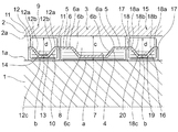
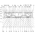
図1は、本発明の第一実施形態に係る転がり軸受の概略を示し、本実施形態では、中央列の針状ころ軸受3と、左側列(図1に向かって左側の列)の針状ころ軸受9及び右側列(図1に向かって右側列)の針状ころ軸受15が、それぞれ別体の保持器4,10,16と針状ころ8,14,20で構成されている複列で別体のC&R(ケージ&ローラ)仕様のラジアルニードル軸受の一形態を採用している。
中央列の針状ころ軸受3と、左側の針状ころ軸受9と、右側の針状ころ軸受15は、回転可能に構成されている第一部材(回転軸)1の外径1aと、前記第一部材(回転軸)1と相対回転可能に配設されている第二部材(外輪又はハウジング)2の内径2aとの間に組み込まれている。
"First embodiment"
FIG. 1 shows an outline of the rolling bearing according to the first embodiment of the present invention. In this embodiment, a needle roller bearing 3 in the center row and a needle shape in the left row (left row as viewed in FIG. 1). A double row in which the roller bearing 9 and the
The needle roller bearing 3 in the center row, the needle roller bearing 9 on the left side, and the needle roller bearing 15 on the right side have an
中央列の針状ころ軸受3の各ころ8は、左側列の針状ころ軸受9の各ころ14と、右側列の針状ころ軸受15の各ころ20に比して大径に形成されている。それぞれの列3,9,15に組み込まれているころ8,14,20はそれぞれの列において同一径のころを組み込んでいる。
そして、それぞれのころ8,14,20は、それぞれの内部すきま(ラジアルすきま)a,b,bが正すきまである。
また、本実施形態では、中央列のころ8と左列のころ14と右列のころ20は、それぞれ、軸方向で同一位置に配設されるように構成されている。
針状ころの径は、特に限定解釈されるものではなく、それぞれの第一部材1と第二部材2との間に組み込まれた際にそれぞれのころ8,15,20が正すきまa,bをもって組み込み可能な程度の大きさ(径)とすればよい。
Each
The
In the present embodiment, the central row of
The diameter of the needle roller is not particularly limited, and when assembled between the
保持器(ケージ)4(10,16)は、本実施形態では、左右の環状部5・5(11・11,17・17)と、左右の環状部5・5(11・11,17・17)間にわたって架け渡されるとともに、周方向に所定の間隔毎に複数設けられる柱部6(12,18)と、隣り合う柱部6(12,18)間に設けられ転動体である針状ころ8(15,20)を転動可能に保持する複数個のポケット部7(13,19)が形成されている保持器(ケージ)を想定している。各柱部6(12,18)は、左右の環状部5・5(11・11,17・17)から相対向するように水平方向に突出した外径側部6a・6a(12a・12a,18a・18a)と、それぞれの外径側部6a・6a(12a・12a,18a・18a)の遊端側からそれぞれ下り傾斜状に向かい合って形成される傾斜部6b・6b(12b・12b,18b・18b)と、それぞれの傾斜部6b・6b(12b・12b,18b・18b)の遊端側から水平方向に連続して一体に設けられる内径側部6c(12c,18c)とで構成されている(図1参照。)。
なお、保持器(ケージ)4(10,16)の構成は図示形態に限定されることなく、周知一般の保持器(ケージ)が本発明の範囲内において採用可能である。
In this embodiment, the cage (cage) 4 (10, 16) includes left and right
The configuration of the cage (cage) 4 (10, 16) is not limited to the illustrated form, and a well-known general cage (cage) can be employed within the scope of the present invention.
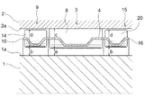
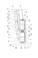
図2はそれぞれの列3,9,15のころ8,14,20が全て正すきまをもって組み込まれていることを理解し易いように、大径ころ8及び小径ころ14,20と回転軸1との間のそれぞれの内部すきま(ラジアルすきま)を極端に大きく表現している概念図である。
大径ころ8と回転軸1の正すきまをa、小径ころ14,20と回転軸1との正すきまをb、大径ころ8の径をc、左右の小径ころ14,20の径をdとすると、内部すきま(ラジアルすきま)の設定は次の式によって表すことができる。
a<b、b=a+ラジアル変位
c>d、d=c−ラジアル変位
なお、ラジアル変位量は、大径ころ8が負荷することができる限界荷重から机上検討を行い算出する。
FIG. 2 shows the large-
The positive clearance between the
a <b, b = a + radial displacement c> d, d = c-radial displacement Note that the radial displacement is calculated from a limit load that can be loaded by the large-
本実施形態によれば、軽荷重(低荷重)時には大径ころ8のみで荷重を負荷し、重荷重(高荷重)時には大径ころ8が変位し、その変位した分、小径ころ14,20も荷重を分担し、大径ころ8のみで荷重を負荷していたときに比して軸受容量が大きくなる。すなわち、本実施形態によれば、ラジアルすきまは大径ころ8も小径ころ14,20も正すきまであるため、ヤング率及び線膨張係数も同じであり、重荷重により大径ころ4がラジアル変位すると、そのラジアル変位の発生に伴う小径ころ14,20の荷重分担により軸受容量が大きくなる(高容量になる)。
このように、径の異なるころ8,14,20を組み込むことにより、軽荷重時(通常時)には転がり軸受としての機能を発揮しつつ、衝撃荷重のような不意に掛かる荷重や、使用上モードにより掛かる過大荷重に対し、軸受容量が大きくなるため、軸受の過大面圧や寿命低下を防ぐことができる。
また、軽荷重時(通常時)には、大径ころ8のみで荷重を受けているためトルクも低く抑えることができる。
さらに、相手部材(例えば軸又はハウジングや外輪内径)の軌道面に段差をつける必要性がないため、軸及びハウジング(外輪内径)への加工手間もない。
また、本実施形態のように、左列の小径の針状ころ軸受9と右列の小径の針状ころ軸受15で中央列の大径の針状ころ軸受3を挟むような形態を採用したため、回転軸(ハウジング)1への組み込み時にミスアライメント状態であったとしても面圧分担にもなる。
According to the present embodiment, the load is applied only by the large-
As described above, by incorporating the
Further, at the time of light load (normal time), since the load is received only by the
Further, since there is no need to make a step on the raceway surface of the mating member (for example, the shaft or the housing or the inner diameter of the outer ring), there is no need to process the shaft and the housing (the outer ring inner diameter).
Further, as in the present embodiment, a configuration is adopted in which the small diameter
なお、図示例では、中央列のころ8を大径のころとし、左右列のころ14,20を小径のころとしているが、中央列のころを小径とし、左右列のころを大径とすることも本発明の範囲内であって適宜設計変更可能である。
また、本実施形態では、それぞれの列には同一径のころを組み込んでいるが、それぞれの列において例えば周方向で交互に大径のころと小径のころを組み込む形態であってもよく本発明の範囲内である。
さらに、本実施形態では、中央列のころ8と左列のころ17と右列のころ20は、それぞれ、軸方向で同一位置に配設されるように構成されているが、それぞれ軸方向で互い違い(千鳥状)に配設されるように構成されるものであってもよく本発明の範囲内である。
本実施形態では三列の実施の一形態をもって説明したが、二列であっても四列以上であってもよく特に限定解釈されるものではない。
また、第一部材1と第二部材2は、本発明の範囲内で適宜選択されるものであり、広く適用可能である。
In the illustrated example, the central row of
Further, in the present embodiment, rollers of the same diameter are incorporated in each row, but for example, a configuration in which a large diameter roller and a small diameter roller are alternately incorporated in the circumferential direction may be incorporated in each row. Is within the range.
Further, in the present embodiment, the
Although this embodiment has been described with one embodiment of three rows, it may be two rows or more than four rows, and is not particularly limited.
The
「第二実施形態」
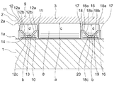
図3は本発明の第二実施形態を示す。
第二実施形態は、第一実施形態における中央列のころ8に、保持器を有さない総ころ形態を採用した実施の一形態である。
その他の構成及び本実施形態の作用効果は第一実施形態と同じである。
"Second embodiment"
FIG. 3 shows a second embodiment of the present invention.
2nd embodiment is one Embodiment which employ | adopted the total roller form which does not have a holder | retainer for the
Other configurations and effects of the present embodiment are the same as those of the first embodiment.
「第三実施形態」
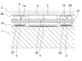
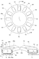
図4は本発明の第三実施形態を示す。
第三実施形態は、第一実施形態と異なり、一つの保持器21でそれぞれの列のころ(中央列のころ8、左列のころ14、右列のころ20)を保持する一体型の軸受形態を採用した実施の一形態である。
保持器21は、円環状に形成されるとともに、周方向で所定の間隔毎に複数個設けられたポケット22が形成されている。本実施形態では、中央列に大径ころ8を組み込むためのポケット22が周方向に複数個形成され、左列と右列には小径ころ14,20を組み込むためのポケット22,22がそれぞれ周方向に複数個形成されている。
その他の構成及び本実施形態の作用効果は第一実施形態と同じである。
"Third embodiment"
FIG. 4 shows a third embodiment of the present invention.
Unlike the first embodiment, the third embodiment is an integrated bearing that holds each row of rollers (
The
Other configurations and effects of the present embodiment are the same as those of the first embodiment.
「第四実施形態」
図5は本発明の第四実施形態を示す。
第四実施形態は、単列のラジアルニードル軸受に本発明を適用した実施の一形態である。
本実施形態は、単一の円環状の保持器23と、保持器23に組み込まれる複数個のころ25,26で…構成されている。保持器23には周方向に所定間隔をあけて複数個のポケット24が形成され、各ポケット24は周方向にわたって大径ころ25と小径ころ26が交互に組み込まれている。
"Fourth embodiment"
FIG. 5 shows a fourth embodiment of the present invention.
The fourth embodiment is an embodiment in which the present invention is applied to a single row radial needle bearing.
This embodiment is composed of a single
本実施形態においても、第一実施形態と同様に、大径ころ25と回転軸1の正すきまをa、小径ころ26と回転軸1との正すきまをb、大径ころ25の径をc、小径ころ26の径をdとすると、内部すきま(ラジアルすきま)の設定は前記第一実施形態と同じ次の式によって表すことができる。
a<b、b=a+ラジアル変位
c>d、d=c−ラジアル変位
In this embodiment, as in the first embodiment, the positive clearance between the
a <b, b = a + radial displacement c> d, d = c-radial displacement
なお、本実施形態では、周方向にわたって大径ころ25と小径ころ26が一つずつ交互に組み込まれているが、例えば2個の大径ころの間に1個の小径ころを交互に介在させた配列構成や、例えば1個の大径ころの間に2個の小径ころを交互に介在させた配列構成など、転がり軸受の使用目的や使用環境に応じて任意の配列構成を適用することができる。
その他の構成及び本実施形態の作用効果は第一実施形態と同じである。
In the present embodiment, the
Other configurations and effects of the present embodiment are the same as those of the first embodiment.
「第五実施形態」
図6は本発明の第五実施形態を示す。
第五実施形態は、シェル形のラジアルニードル軸受に本発明を適用した実施の一形態である。
本実施形態では、薄い鋼板からなるシェル形外輪27に、第一実施形態の複列のラジアルニードル軸受を組み込んだ実施の一形態である。
本実施形態では開放形の一例を示すが、一端密閉形であっても良く適宜選択使用可能である。
"Fifth embodiment"
FIG. 6 shows a fifth embodiment of the present invention.
The fifth embodiment is an embodiment in which the present invention is applied to a shell-type radial needle bearing.
This embodiment is an embodiment in which the double-row radial needle bearing of the first embodiment is incorporated into a shell-shaped
In the present embodiment, an example of an open type is shown, but a one-end sealed type may be used as appropriate.
本実施形態では、シェル形外輪27に組み込まれる軸受として、第一実施形態のラジアルニードル軸受を適用しているが、第二実施形態乃至第四実施形態のラジアルニードル軸受を適用することも可能で本発明の範囲内である。また、ケージを有さない総ころ形態であってもよい。
なお、シェル形の外輪に代えて、ソリッド(削り出し)の外輪に第一実施形態乃至第四実施形態の軸受を組み込んだソリッド形のラジアルニードル軸受としてもよく本発明の範囲内である。さらに、内輪付きの形態であっても構わない。
その他の構成及び本実施形態の作用効果は第一実施形態乃至第四実施形態と同じである。
In the present embodiment, the radial needle bearing of the first embodiment is applied as the bearing incorporated in the shell-shaped
Instead of the shell-shaped outer ring, a solid radial needle bearing in which the bearing of the first embodiment to the fourth embodiment is incorporated in a solid (machined) outer ring may be within the scope of the present invention. Furthermore, it may be a form with an inner ring.
Other configurations and effects of the present embodiment are the same as those of the first to fourth embodiments.
「第六実施形態」
図7は本発明の第六実施形態で、本発明を第一部材(例えばレース)1と第二部材(例えば図示しないレース)との間に配設されるスラストニードル軸受に適用した実施の一形態の概略を示す。
本実施形態では、内側列(図7に向かって右側の列)の針状ころ軸受28と外側列(図6に向かって左側の列)の針状ころ軸受35が、それぞれ別体の保持器(ケージ)30,37と針状ころ34,41で構成されている複列で別体のC&R(ケージ&ローラ)仕様のスラストルニードル軸受の一形態を採用している。
"Sixth embodiment"
FIG. 7 shows a sixth embodiment of the present invention in which the present invention is applied to a thrust needle bearing disposed between a first member (for example, a race) 1 and a second member (for example, a not-shown race). The outline of a form is shown.
In the present embodiment, the
外側列の針状ころ軸受35の各ころ41は、内側列の針状ころ軸受28の各ころ34に比して大径に形成されている。それぞれの列に組み込まれているころ34,41はそれぞれの列において同一径のころを組み込んでいる。
そして、それぞれのころ34,41は、それぞれの内部すきま(ラジアルすきま)a,b,bが正すきまである。
また、本実施形態では、外側列のころ41と内側列のころ34は、それぞれ、軸心A1方向(径方向)で同一位置に配設されるように構成されている。
針状ころの径は、特に限定解釈されるものではなく、それぞれ第一部材1と第二部材との間に組み込まれた際にそれぞれのころ34,41が正すきまをもって組み込み可能な程度の大きさ(径)とすればよい。
Each
The
In the present embodiment, the
The diameter of the needle roller is not particularly limited and is large enough to allow each of the
外側列に配される大径の第一ケージ37と、内側列に配される小径の第二ケージ30が同心に配されている。
第一ケージ37と第二ケージ30はそれぞれ大きさ(径方向大きさ)が異なるだけでその他は同一であるため、本実施形態では第一ケージ37についてのみ説明し第二ケージ30については符合のみ記載してその説明は省略する。
A large-diameter
Since the
第一ケージ37(第二ケージ30)は、鋼材などで薄肉状に形成された第一円環部38(31)と第二円環部39(32)を組み合わせて中空円環状に構成されている。 The first cage 37 (second cage 30) is formed in a hollow annular shape by combining a first annular portion 38 (31) and a second annular portion 39 (32) formed in a thin shape with a steel material or the like. Yes.
第一円環部38(31)は、環状板部38a(31a)と、環状板部38a(31a)の内外縁からそれぞれ鉛直方向に連続して設けられた環状外壁部38b(31b)と環状内壁部38c(31c)で構成された断面視で略コの字状に形成され、環状板部38a(31a)の周方向に所定間隔をあけて複数個の貫通孔38d(31d)が形成されている。
一方、第二円環部39(32)は、第一円環部38(31)と同じく、環状板部39a(32a)と、環状板部39a(32a)の内外縁からそれぞれ鉛直方向に連続して設けられた環状外壁部39b(32b)と環状内壁部39c(32c)で構成された断面視で略コの字状に形成され、環状板部39a(32a)の周方向に所定間隔をあけて複数個の貫通孔39d(32d)が形成されている。
第二円環部39(32)は、第一円環部38(31)の環状外壁部38b(31b)と環状内壁部38c(31c)との間の空間に収まる程度に第一円環部38(31)と比して小さく形成されている。
そして、前記貫通孔38d,39d(31d,32d)で形成されたポケット340(33)にて、各ころ41(34)が転動可能に保持されている。
なお、保持器(ケージ)構成は図示形態に限定されることなく、周知一般の保持器(ケージ)が本発明の範囲内において採用可能である。
The first annular portion 38 (31) is annular with an
On the other hand, the second annular portion 39 (32) is continuous in the vertical direction from the
The second annular portion 39 (32) is positioned so as to fit in the space between the annular
Each roller 41 (34) is rotatably held in a pocket 340 (33) formed by the through
The cage structure is not limited to the illustrated form, and a well-known general cage can be used within the scope of the present invention.
本実施形態において、大径ころ41と第一部材(例えばレース)1の面部1aとの正すきまをa、小径ころ34と第一部材(例えばレース)1の面部1aとの正すきまをb、大径ころ41の径をc、小径ころ34の径をdとすると、内部すきま(ラジアルすきま)の設定は前記第一実施形態と同じ次の式によって表すことができる。
a<b、b=a+ラジアル変位
c>d、d=c−ラジアル変位
In the present embodiment, the positive clearance between the
a <b, b = a + radial displacement c> d, d = c-radial displacement
本実施形態によれば、軽荷重(低荷重)時には外側列の大径のころ41のみで荷重を負荷し、重荷重(高荷重)時には大径ころ41が変位し、その変位した分、内側列の小径のころ34も荷重を分担し、大径のころ41のみで荷重を負荷していたときに比して軸受容量が大きくなる。
According to the present embodiment, when a light load (low load) is applied, a load is applied only by the large-
なお、図示例では、外側列のころを大径のころ41とし、内側列のころを小径のころ34としているが、外側列のころを小径とし、内側列のころを大径とすることも本発明の範囲内であって適宜設計変更可能である。
また、本実施形態では、それぞれの列には同一径のころを組み込んでいるが、それぞれの列において例えば周方向で交互に大径のころと小径のころを組み込む形態であってもよく本発明の範囲内である。
さらに、本実施形態では、外側列のころ41と内側列のころ34は、それぞれ、軸心A1方向(径方向)で同一位置に配設されるように構成されているが、それぞれ軸方向で互い違い(千鳥状)に配設されるように構成されるものであってもよく本発明の範囲内である。
本実施形態では、軸心A1方向(径方向)で二列の実施の一形態をもって説明したが、三列以上であってもよく特に限定解釈されるものではない。
その他の構成及び作用効果は第一実施形態と同じである。
In the illustrated example, the outer row of rollers is a
Further, in the present embodiment, rollers of the same diameter are incorporated in each row, but for example, a configuration in which a large diameter roller and a small diameter roller are alternately incorporated in the circumferential direction may be incorporated in each row. Is within the range.
Furthermore, in the present embodiment, the
In the present embodiment, the description has been given with the embodiment of the two rows in the axial center A1 direction (radial direction), but there may be three or more rows, and is not particularly limited.
Other configurations and operational effects are the same as those of the first embodiment.
「第七実施形態」
図8は本発明の第七実施形態を示す。
第七実施形態は、第六実施形態と異なり、一つの保持器(ケージ)42でそれぞれの列のころ(外側列のころ46、内側列のころ47)を保持する一体型の軸受形態を採用した実施の一形態である。
"Seventh embodiment"
FIG. 8 shows a seventh embodiment of the present invention.
Unlike the sixth embodiment, the seventh embodiment adopts an integrated bearing configuration in which the rollers (
保持器42は、鋼材などで薄肉状に形成された第一円環部43と第二円環部44を組み合わせて中空円環状に構成されている。
The
第一円環部43は、環状板部43aと、環状板部43aの内外縁からそれぞれ鉛直方向に連続して設けられた環状外壁部43bと環状内壁部43cで構成された断面視で略コの字状に形成され、環状板部43aの周方向に所定間隔をあけて複数個の貫通孔43dが形成されており、このような周方向に設けられた貫通孔43dの列が径方向に複列で設けられている。本実施形態では、外側列と内側列の二列で設けられている。
一方、第二円環部44は、第一円環部43と同じく、環状板部44aと、環状板部44aの内外縁からそれぞれ鉛直方向に連続して設けられた環状外壁部44bと環状内壁部44cで構成された断面視で略コの字状に形成され、前記第一円環部43の貫通孔43dと同一位置に複数個の貫通孔44dが形成されている。
第二円環部44は、第一円環部43の環状外壁部43bと環状内壁部43cとの間の空間に収まる程度に第一円環部43と比して小さく形成されている。
そして、前記貫通孔43d,44dで形成されたポケット45にて、各ころが46,47転動可能に保持されている。本実施形態では第七実施形態と同様に外側列に大径のころ46、内側列に小径のころ47が組み込まれている。
なお、保持器(ケージ)構成は図示形態に限定されることなく、周知一般の保持器(ケージ)が本発明の範囲内において採用可能である。
その他の構成及び本実施形態の作用効果は第一実施形態及び第六実施形態と同じである。
The first
On the other hand, the second
The second
Each roller is held so as to be able to roll 46, 47 in a
The cage structure is not limited to the illustrated form, and a well-known general cage can be used within the scope of the present invention.
Other configurations and operational effects of the present embodiment are the same as those of the first embodiment and the sixth embodiment.
「第八実施形態」
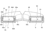
図9は、本発明の第八実施形態を示す。
第八実施形態は、単列のラジアルニードル軸受に本発明を適用した実施の一形態である。
本実施形態は、単一の円環状の保持器48と、保持器48に組み込まれる複数個のころ52,53で構成されている。保持器48は第七実施形態と同様に第一円環部49と第二円環部50で構成されているが、保持器48には単列で、周方向にわたって所定間隔毎に複数個のポケット51が形成され、ころは周方向にわたって大径ころ52と小径ころ53が交互に組み込まれている。
"Eighth embodiment"
FIG. 9 shows an eighth embodiment of the present invention.
The eighth embodiment is an embodiment in which the present invention is applied to a single-row radial needle bearing.
The present embodiment includes a single
第一円環部49は、環状板部49aと、環状板部49aの内外縁からそれぞれ鉛直方向に連続して設けられた環状外壁部49bと環状内壁部49cで構成された断面視で略コの字状に形成され、環状板部49aの周方向に所定間隔をあけて複数個の貫通孔49dが形成されており、このような周方向に設けられた貫通孔49dの列が径方向に複列で設けられている。
一方、第二円環部50は、第一円環部49と同じく、環状板部50aと、環状板部50aの内外縁からそれぞれ鉛直方向に連続して設けられた環状外壁部50bと環状内壁部50cで構成された断面視で略コの字状に形成され、前記第一円環部49の貫通孔49dと同一位置に複数個の貫通孔50dが形成されている。
第二円環部50は、第一円環部49の環状外壁部49bと環状内壁部49cとの間の空間に収まる程度に第一円環部49と比して小さく形成されている。
そして、前記貫通孔49d,50dで形成されたポケット51にて、各ころ52,53が転動可能に保持されている。本実施形態では第七実施形態と同様に外側列に大径のころ52、内側列に小径のころ53が組み込まれている。
なお、保持器(ケージ)構成は図示形態に限定されることなく、周知一般の保持器(ケージ)が本発明の範囲内において採用可能である。
The first annular portion 49 is substantially in a cross-sectional view composed of an
On the other hand, the second
The second
The
The cage structure is not limited to the illustrated form, and a well-known general cage can be used within the scope of the present invention.
本実施形態においても、第六実施形態と同様に、大径ころ52と第一部材(例えばレース)1の面部1aとの正すきまをa、小径ころ53と第一部材(例えばレース)1の面部1aとの正すきまをb、大径ころ52の径をc、小径ころ53の径をdとすると、内部すきま(ラジアルすきま)の設定は前記第一実施形態と同じ次の式によって表すことができる。
a<b、b=a+ラジアル変位
c>d、d=c−ラジアル変位
なお、ラジアル変位量は、大径ころ8が負荷することができる限界荷重から机上検討を行い算出する。
そして、それぞれのころ52,53は、それぞれの内部すきま(ラジアルすきま)a,bが正すきまである。
Also in this embodiment, as in the sixth embodiment, the correct clearance between the
a <b, b = a + radial displacement c> d, d = c-radial displacement Note that the radial displacement is calculated from a limit load that can be loaded by the large-
The
なお、本実施形態では、周方向にわたって大径ころ46と小径ころ47が一つずつ交互に組み込まれているが、例えば2個の大径ころの間に1個の小径ころを交互に介在させた配列構成や、例えば1個の大径ころの間に2個の小径ころを交互に介在させた配列構成など、転がり軸受の使用目的や使用環境に応じて任意の配列構成を適用することができる。
その他の構成及び本実施形態の作用効果は第一実施形態、第六実施形態及び第七実施形態と同じである。
In the present embodiment, one
Other configurations and operational effects of the present embodiment are the same as those of the first embodiment, the sixth embodiment, and the seventh embodiment.
「第九実施形態」
図10は、本発明の第九実施形態を示す。
第九実施形態は、第八実施形態の単列のラジアルニードル軸受を外側レース(外輪)54と内側レース(内輪)55で覆って一体化した実施の一形態である。
なお、第六実施形態第八実施形態のスラストニードル軸受を適用することも可能で本発明の範囲内である。
その他の構成及び作用効果は第一実施形態、第六実施形態乃至第八実施形態と同じである。
"Ninth embodiment"
FIG. 10 shows a ninth embodiment of the present invention.
The ninth embodiment is an embodiment in which the single row radial needle bearing of the eighth embodiment is covered and integrated with an outer race (outer ring) 54 and an inner race (inner ring) 55.
In addition, it is also possible to apply the thrust needle bearing of 6th embodiment 8th embodiment, and it is in the scope of the present invention.
Other configurations and operational effects are the same as those of the first embodiment and the sixth to eighth embodiments.
本実施形態では、各種車両の変速機、建設機械用の変速機、ポンプ等の各種産業機械用の変速機等に用いられる転がり軸受をもって説明したが、特に、衝撃荷重や過大荷重が掛かり易い箇所に配設される可能性のある転がり軸受であれば広く利用可能である。
また、本実施形態では針状ころ軸受をもって説明したが、玉軸受にも利用可能である。
In the present embodiment, the description has been given with the rolling bearings used for various vehicle transmissions, transmissions for construction machines, transmissions for various industrial machines such as pumps, etc., but in particular, locations where impact loads and overloads are likely to be applied. If it is a rolling bearing which may be arrange | positioned, it can utilize widely.
Moreover, although this embodiment demonstrated with the needle roller bearing, it can utilize also for a ball bearing.
1 第一部材
2 第二部材
8 中央列のころ
14 左列のころ
20 右列のころ
a 隙間(大径ころと第一部材との隙間)
b 隙間(小径ころと第一部材との隙間)
c ころ径(大径ころの径)
d ころ径(小径ころの径)
DESCRIPTION OF
b Gap (gap between small diameter roller and first member)
c Roller diameter (diameter of large diameter roller)
d Roller diameter (diameter of small diameter roller)
Claims (2)
大小径の異なる転動体が組み込まれ、かつそれぞれの転動体は正すきまをもって組み込まれており、
軽荷重時は径の大きな転動体のみで荷重を負荷し、
不意の衝撃荷重や高荷重が掛かったときには径の大きい転動体に加え、径の小さい転動体でも荷重を負荷することを特徴とする転がり軸受。 A rolling bearing disposed between a first member and a second member capable of relative rotation,
Rolling elements with different large and small diameters are incorporated, and each rolling element is incorporated with a positive clearance,
At light load, load only with rolling elements with large diameter,
A rolling bearing characterized in that when a sudden impact load or a high load is applied, in addition to a rolling element having a large diameter, a rolling element having a small diameter is loaded.
The rolling bearing according to claim 1, wherein the rolling elements are incorporated in a double row, and the diameters of the rolling elements incorporated in one row and the rolling members incorporated in another row are different.
Priority Applications (1)
| Application Number | Priority Date | Filing Date | Title |
|---|---|---|---|
| JP2014249067A JP2016109253A (en) | 2014-12-09 | 2014-12-09 | Rolling bearing |
Applications Claiming Priority (1)
| Application Number | Priority Date | Filing Date | Title |
|---|---|---|---|
| JP2014249067A JP2016109253A (en) | 2014-12-09 | 2014-12-09 | Rolling bearing |
Publications (2)
| Publication Number | Publication Date |
|---|---|
| JP2016109253A true JP2016109253A (en) | 2016-06-20 |
| JP2016109253A5 JP2016109253A5 (en) | 2018-01-25 |
Family
ID=56123762
Family Applications (1)
| Application Number | Title | Priority Date | Filing Date |
|---|---|---|---|
| JP2014249067A Pending JP2016109253A (en) | 2014-12-09 | 2014-12-09 | Rolling bearing |
Country Status (1)
| Country | Link |
|---|---|
| JP (1) | JP2016109253A (en) |
Cited By (6)
| Publication number | Priority date | Publication date | Assignee | Title |
|---|---|---|---|---|
| JP2018111139A (en) * | 2017-01-06 | 2018-07-19 | 株式会社メディカロイド | Joint driving mechanism of multijoint robot arm, multijoint robot arm, and robot operating table |
| FR3100294A1 (en) * | 2019-08-29 | 2021-03-05 | Airbus Helicopters | Assembly provided with a rotating member and at least one bearing system, power transmission box and aircraft |
| WO2022210339A1 (en) * | 2021-03-31 | 2022-10-06 | ミネベアミツミ株式会社 | Roller bearing and planetary speed reduction gear |
| DE102022110308A1 (en) | 2022-04-28 | 2023-11-02 | Schaeffler Technologies AG & Co. KG | Axial bearing arrangement with bearing rollers surrounded by a multi-part bearing cage |
| DE102022110323A1 (en) | 2022-04-28 | 2023-11-02 | Schaeffler Technologies AG & Co. KG | Axial bearing arrangement with bearing rollers surrounded by a multi-part bearing cage |
| DE102022110311A1 (en) | 2022-04-28 | 2023-11-02 | Schaeffler Technologies AG & Co. KG | Axial bearing arrangement with bearing rollers surrounded by a multi-part bearing cage |
Citations (3)
| Publication number | Priority date | Publication date | Assignee | Title |
|---|---|---|---|---|
| JPH031531B2 (en) * | 1987-05-30 | 1991-01-10 | Shinnippon Seitetsu Kk | |
| JPH06304616A (en) * | 1993-04-22 | 1994-11-01 | Koyo Seiko Co Ltd | Bearing device of roll neck for rolling mill |
| JP2006250187A (en) * | 2005-03-08 | 2006-09-21 | Nsk Ltd | Flat bearing |
-
2014
- 2014-12-09 JP JP2014249067A patent/JP2016109253A/en active Pending
Patent Citations (3)
| Publication number | Priority date | Publication date | Assignee | Title |
|---|---|---|---|---|
| JPH031531B2 (en) * | 1987-05-30 | 1991-01-10 | Shinnippon Seitetsu Kk | |
| JPH06304616A (en) * | 1993-04-22 | 1994-11-01 | Koyo Seiko Co Ltd | Bearing device of roll neck for rolling mill |
| JP2006250187A (en) * | 2005-03-08 | 2006-09-21 | Nsk Ltd | Flat bearing |
Cited By (6)
| Publication number | Priority date | Publication date | Assignee | Title |
|---|---|---|---|---|
| JP2018111139A (en) * | 2017-01-06 | 2018-07-19 | 株式会社メディカロイド | Joint driving mechanism of multijoint robot arm, multijoint robot arm, and robot operating table |
| FR3100294A1 (en) * | 2019-08-29 | 2021-03-05 | Airbus Helicopters | Assembly provided with a rotating member and at least one bearing system, power transmission box and aircraft |
| WO2022210339A1 (en) * | 2021-03-31 | 2022-10-06 | ミネベアミツミ株式会社 | Roller bearing and planetary speed reduction gear |
| DE102022110308A1 (en) | 2022-04-28 | 2023-11-02 | Schaeffler Technologies AG & Co. KG | Axial bearing arrangement with bearing rollers surrounded by a multi-part bearing cage |
| DE102022110323A1 (en) | 2022-04-28 | 2023-11-02 | Schaeffler Technologies AG & Co. KG | Axial bearing arrangement with bearing rollers surrounded by a multi-part bearing cage |
| DE102022110311A1 (en) | 2022-04-28 | 2023-11-02 | Schaeffler Technologies AG & Co. KG | Axial bearing arrangement with bearing rollers surrounded by a multi-part bearing cage |
Similar Documents
| Publication | Publication Date | Title |
|---|---|---|
| JP2016109253A (en) | Rolling bearing | |
| JP6047999B2 (en) | Rotating support device | |
| JPWO2011062269A1 (en) | Rotation support device for pinion shaft | |
| RU2570891C1 (en) | Ball cageless roll bearing | |
| RU2523871C1 (en) | Ball cageless bearing | |
| JP2009036348A (en) | Tandem type double-row angular contact ball bearing and bearing device for pinion shaft | |
| JP2006200677A (en) | Thrust ball bearing | |
| JP2012202453A (en) | Self-aligning roller bearing | |
| JP2010255778A (en) | Radial needle bearing | |
| JP2012246972A (en) | Roller thrust bearing | |
| US20190010985A1 (en) | Segmented cage for rolling bearing | |
| JP2016102525A (en) | Self-aligning roller bearing | |
| JP5636887B2 (en) | Tandem angular contact ball bearings | |
| RU2523872C1 (en) | Ball cageless bearing | |
| JP5434519B2 (en) | Double row tapered roller bearing device | |
| JP2012149703A (en) | Self-alignment roller bearing | |
| JP2006144921A (en) | Rolling bearing | |
| JP5012383B2 (en) | Radial roller bearing with cage | |
| JP2017078480A (en) | Self-aligning roller bearing | |
| JP6236754B2 (en) | Tandem double-row angular contact ball bearing, differential device, and automobile | |
| JP2006258262A (en) | Double-row rolling bearing | |
| JP2011106633A (en) | Tandem type double row angular contact ball bearing | |
| JP5803234B2 (en) | Tandem angular contact ball bearings | |
| JP6205690B2 (en) | Tandem type double row angular contact ball bearing | |
| JP6141606B2 (en) | Spherical roller bearing |
Legal Events
| Date | Code | Title | Description |
|---|---|---|---|
| A521 | Request for written amendment filed |
Free format text: JAPANESE INTERMEDIATE CODE: A523 Effective date: 20171207 |
|
| A621 | Written request for application examination |
Free format text: JAPANESE INTERMEDIATE CODE: A621 Effective date: 20171207 |
|
| A977 | Report on retrieval |
Free format text: JAPANESE INTERMEDIATE CODE: A971007 Effective date: 20180830 |
|
| A131 | Notification of reasons for refusal |
Free format text: JAPANESE INTERMEDIATE CODE: A131 Effective date: 20180911 |
|
| A02 | Decision of refusal |
Free format text: JAPANESE INTERMEDIATE CODE: A02 Effective date: 20190312 |