JP4132986B2 - Swing type vehicle - Google Patents
Swing type vehicle Download PDFInfo
- Publication number
- JP4132986B2 JP4132986B2 JP2002157843A JP2002157843A JP4132986B2 JP 4132986 B2 JP4132986 B2 JP 4132986B2 JP 2002157843 A JP2002157843 A JP 2002157843A JP 2002157843 A JP2002157843 A JP 2002157843A JP 4132986 B2 JP4132986 B2 JP 4132986B2
- Authority
- JP
- Japan
- Prior art keywords
- swing
- brake
- braking
- wheel
- rocking
- Prior art date
- Legal status (The legal status is an assumption and is not a legal conclusion. Google has not performed a legal analysis and makes no representation as to the accuracy of the status listed.)
- Expired - Lifetime
Links
Images


Classifications
-
- B—PERFORMING OPERATIONS; TRANSPORTING
- B62—LAND VEHICLES FOR TRAVELLING OTHERWISE THAN ON RAILS
- B62K—CYCLES; CYCLE FRAMES; CYCLE STEERING DEVICES; RIDER-OPERATED TERMINAL CONTROLS SPECIALLY ADAPTED FOR CYCLES; CYCLE AXLE SUSPENSIONS; CYCLE SIDE-CARS, FORECARS, OR THE LIKE
- B62K5/00—Cycles with handlebars, equipped with three or more main road wheels
- B62K5/02—Tricycles
- B62K5/027—Motorcycles with three wheels
-
- B—PERFORMING OPERATIONS; TRANSPORTING
- B62—LAND VEHICLES FOR TRAVELLING OTHERWISE THAN ON RAILS
- B62K—CYCLES; CYCLE FRAMES; CYCLE STEERING DEVICES; RIDER-OPERATED TERMINAL CONTROLS SPECIALLY ADAPTED FOR CYCLES; CYCLE AXLE SUSPENSIONS; CYCLE SIDE-CARS, FORECARS, OR THE LIKE
- B62K5/00—Cycles with handlebars, equipped with three or more main road wheels
- B62K5/10—Cycles with handlebars, equipped with three or more main road wheels with means for inwardly inclining the vehicle body on bends
-
- B—PERFORMING OPERATIONS; TRANSPORTING
- B62—LAND VEHICLES FOR TRAVELLING OTHERWISE THAN ON RAILS
- B62K—CYCLES; CYCLE FRAMES; CYCLE STEERING DEVICES; RIDER-OPERATED TERMINAL CONTROLS SPECIALLY ADAPTED FOR CYCLES; CYCLE AXLE SUSPENSIONS; CYCLE SIDE-CARS, FORECARS, OR THE LIKE
- B62K5/00—Cycles with handlebars, equipped with three or more main road wheels
- B62K2005/001—Suspension details for cycles with three or more main road wheels
Landscapes
- Engineering & Computer Science (AREA)
- Mechanical Engineering (AREA)
- Braking Arrangements (AREA)
- Automatic Cycles, And Cycles In General (AREA)
- Regulating Braking Force (AREA)
- Transmission Of Braking Force In Braking Systems (AREA)
Description
【0001】
【発明の属する技術分野】
本発明は、揺動式車両における揺動制御に関する。
【0002】
【従来の技術】
揺動式車両には、走行時に例えば前車体と後車体が互いに左右に揺動するようにしてカーブを曲がる際の旋回走行を安定化させたものがある。
【0003】
しかし停車時には、前車体または後車体が揺動すると自立できなくなり運転者は足を地面に着いて倒れないように保たなければならないので、両車体が互いに揺動しないように一体化すれば自立を維持することができる。
【0004】
実公昭63−45361号公報に記載された例では、揺動式3輪車においてパーキングレバーの操作により前車体と後車体の連結部の揺動を規制するようにしている。
また特公昭61−32196号公報に記載された例は、ブレーキレバーの操作により後輪ブレーキを作動させるとともに前車体と後車体の揺動規制装置を同時に作動させるものである。
【0005】
さらに車速に応じて前車体と後車体の相対揺動を電子制御する例(特開昭59−120586号公報)がある。
同例では減速時に比較的早い車速から揺動を規制している。
【0006】
【発明が解決しようとする課題】
前記パーキングレバーの操作で前車体と後車体の連結部の揺動を規制する例(実公昭63−45361号公報)の場合は、減速停車する際にはブレーキレバーを操作して停止した後、ブレーキレバーから手を離し、別のパーキングレバーを操作して揺動を規制する必要があり、さらに停止後再発進する場合は、パーキングレバーを操作する必要がある。
このように運転者に複数の操作を順次行うことが要求される。
【0007】
またブレーキレバー操作により後輪制動と揺動規制とを同時に行う例(特公昭61−32196号公報)の場合は、ブレーキ操作による減速走行中における進路変更等がし難い場合がある。
【0008】
車速に応じて前車体と後車体の相対揺動を電子制御する例(特開昭59−120586号公報)では、比較的早い車速から揺動を規制しているので減速走行中の進路変更等がし難くなる場合があるとともに、システムの構成が複雑になり、かつ信頼性を確保する観点からコスト高となる。
【0009】
本発明は、斯かる点に鑑みなされたもので、その目的とする処は、制動・停車さらに再発進の際の制動および揺動制御の操作性が良く制動走行中の進路変更も容易で複雑なシステムを要しない揺動式車両を供する点にある。
【0010】
【課題を解決するための手段および作用効果】
上記目的を達成するために、本発明は、揺動機構を備えた揺動式車両において、
前記揺動機構の相対的揺動を規制する揺動固定機構と、ブレーキ操作手段の操作により発生する制動操作力が作用することで前記前輪または後輪を制動する制動機構と、車両が走行状態から停止状態になるまでは、前記ブレーキ操作手段の操作により発生する制動操作力を、前記前輪または後輪を制動する前記制動機構にのみに作用させ、車両が走行状態から停止状態になった後は、前記揺動固定機構にも前記ブレーキ操作手段の操作により発生している制動操作力の一部を作用させ前記揺動機構の相対的揺動を規制する揺動固定制御機構とを備えた揺動式車両とした。
【0011】
制動操作により制動機構を作動して制動し停止すると、揺動固定機構を作動して揺動機構の相対的揺動を規制するので、制動操作のみで揺動機構の制御も実行され、制動・停車さらに再発進の際の制動機構および揺動機構の制御の操作性が良い。
【0012】
揺動固定制御機構は、制動走行中は揺動固定機構による揺動機構の規制を行わないよう制御するので、制動走行中の進路変更も容易に行える。
【0014】
揺動固定機構にも制動機構の制動操作力の一部を作用させて揺動を規制するので、揺動固定機構を作動する動力源を別途設ける必要がなく構造を簡素化し小型化を図ることができる。
【0015】
請求項2記載の発明は、請求項1記載の揺動式車両において、前記制動機構は、作動部を保持する機構保持部が車輪の回転方向に所要小角度回動可能に設けられ、前記揺動固定制御機構は、前記制動機構に作用する前記制動操作力の一部が前記機構保持部を車輪の前進回転方向と反対方向に付勢するよう構成され、制動された車輪が停止したとき前記制動操作力の一部が前記機構保持部を車輪の前進回転方向と反対方向に回動することで前記揺動固定機構を作動して前記揺動機構の揺動を規制することを特徴とする。
【0016】
制動時には制動機構は作動部が車輪に作用して停止しようとするので、作動部およびこれを保持する機構保持部は車輪の前進回転方向に付勢されており、この制動トルクは、機構保持部を車輪の前進回転方向と反対方向に回動しようとする制動操作力の一部より大きい状態にあるが、停車時に車輪が停止すると制動トルクが略0となり、制動操作力の一部が働き機構保持部を車輪の前進回転方向と反対方向に回動し、揺動固定機構を作動して揺動機構の揺動を規制することができる。
【0017】
運転者は、ブレーキ操作手段を操作するだけで制動とともに車輪停止時の揺動機構の規制制御も行うことができるので、操作性が良い。
停車後の再発進もブレーキ操作手段を解放操作するだけで、揺動機構の規制は解除された状態で走行に入ることができる。
揺動固定制御機構は電子制御方式を採らずに機械制御とし簡素で廉価なシステムを提供することができる。
【0018】
請求項3記載の発明は、請求項1または請求項2記載の揺動式車両において、前記制動機構に作用する前記制動操作力は、油圧による力であることを特徴とする。
【0019】
油圧により制動操作力を得るようにしているので、制動が良好であるとともに、コンパクトな構成で揺動規制制御を行うことができる。
【0020】
請求項4記載の発明は、請求項2記載の揺動式車両において、前記制動機構が、前記作動部であるキャリパピストンを前記機構保持部であるキャリパブラケットが保持し、前記キャリパピストンが作動して車輪と一体のディスクプレートを挟んで制動する油圧式ディスクブレーキ機構であることを特徴とする。
【0021】
制動油圧の一部がキャリパブラケットを車輪の前進回転方向と反対方向に付勢するようにし、減速停止時に揺動固定機構を作動して揺動機構の揺動を規制することができる。
このように油圧式ディスクブレーキ機構に本揺動固定機構を容易に組み込むことができる。
【0022】
【発明の実施の形態】
以下本発明に係る一実施の形態について図1ないし図4に基づき説明する。
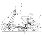
本実施の形態は、揺動式自動3輪車1に係り、車体が1個の操向前輪4を有する前車体2と2個の駆動後輪5,5を左右に有する後車体3に分割されている。
【0023】
前車体2は、ヘッドパイプ6から下方へ延びた車体フレーム7が水平後方へ屈曲してステップ部7aを形成し、さらに後部で斜め上方へ立ち上がって上端にシート部7bを形成している。
【0024】
車体フレーム7のステップ部7aに一体に突設された連結ブラケット8にピボット軸9を介してジョイントケース10が前端を枢支されて上下に揺動自在に設けられている。
【0025】
ジョイントケース10内には軸受12およびナイトハルト機構13が設けられ、他方の後車体3から前方へ突出する揺動軸14がジョイントケース10に後方から挿入されて軸受12に揺動(回動)自在に支持されナイトハルト機構13に係合され、該ジョイントケース10内の軸受12とナイトハルト機構13および揺動軸14とにより構成される揺動機構11により前車体2と後車体3が連結される。
【0026】
前車体2と後車体3は軸受12により互いに左右に揺動自在に連結されるとともにナイトハルト機構13により両者は弾性的に中立状態に復帰するように付勢される。
【0027】
ジョイントケース10と車体フレーム7との間には緩衝器15が介装されて後車体3の上下の揺動を緩衝している。
後車体3には内燃機関16が搭載されて減速機構16aを介して後輪5,5が駆動される。
【0028】
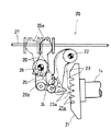
ジョイントケース10内の前部には揺動固定機構20が設けられている。
図2に示すように揺動軸14の前端にはスイングロックプレート21が一体に固着されており、同スイングロックプレート21は外周縁が前方に延出していてその一部所要部分に係止溝21aが5つ程形成されている。
【0029】
スイングロックプレート21の前方に、ピン22に枢着された係止部材23がその係止突起23aを係止溝21aに係止可能に配設されており、係止部材23はリンク部材24を介してピン25に枢着されたアーム部材26の一端26bと連結されている。
アーム部材26の他端26aは揺動固定ケーブル27に係合している。
なお揺動固定ケーブル27は、図示されないが付勢手段により図2において右方に付勢されている。
【0030】
いま図2に実線で示すように係止部材23がスイングロックプレート21に係止していないフリーの状態において、揺動固定ケーブル27が引かれると、2点鎖線で示すようにアーム部材26が回動し、リンク部材24を介して係止部材23が揺動して係止突起23aをスイングロックプレート21の係止溝21aに係止して揺動軸14の揺動をロックすることができる。
すなわち前車体2と後車体3との相対的な左右への揺動が禁止され固定される。
【0031】
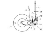
本揺動式自動3輪車1の前輪4のブレーキ機構は油圧式ディスクブレーキ機構30であり、前輪4を軸支するフロントフォーク19にブレーキキャリパ32が取り付けられ、油圧により駆動するキャリパピストン32aがパッド32bを介して前輪4と一体に回転するディスクプレート31を挟み制動する。
【0032】
前車体2のヘッドパイプ6に回動自在に支持されたステアリングシャフトの上部において左右に展開したハンドル17,17の一方に沿ってフロントブレーキレバー18が設けられており、同フロントブレーキレバー18の操作によりマスタシリンダ(図示せず)のピストンを押して油圧をブレーキキャリパ32に供給しキャリパピストン32aを作動してブレーキを掛ける構成である。
【0033】
ブレーキキャリパ32は、キャリパブラケット41に一体に固着され、キャリパブラケット41は、下端部41aがフロントフォーク19の下端の前車軸4aに枢着されて前車軸4aを中心に揺動自在に支持されるとともに、上端部41bがフロントフォーク19との間に介装された引張りスプリング42を介して弾性的に支持されている。
【0034】
キャリパブラケット41の突出部41cにはセカンダリシリンダ43が固着されており、このセカンダリシリンダ43に摺動自在に嵌挿されたピストンロッド43aは、その基端部がフロントフォーク19に一体に突設された支持ブラケット44にピン45を介して枢着されている。
【0035】
セカンダリシリンダ43にはブレーキキャリパ32に供給される油圧の一部が供給されるようになっており、この油圧によりピストンロッド43aを押出し方向に付勢するので、車体側に枢着されたピストンロッド43aのため揺動可能なセカンダリシリンダ43をキャリパブラケット41とともに引張りスプリング42に抗して図3において時計回りに付勢する。
【0036】
キャリパブラケット41の中央部には長孔43dが形成されていて、支持ブラケット44に突設されたストッパピン46が同長孔43dに挿入されていて、キャリパブラケット41の揺動範囲を所要の小角度に規制している。
【0037】
そしてキャリパブラケット41の上部の屈曲部41eに前記揺動固定ケーブル27が結着されている。
揺動固定ケーブル27はケーブルホルダー28からケーブルアウタ29内に摺動自在に嵌挿されて前記揺動固定機構20に回送されてアーム部材26に連結される(図2参照)。
【0038】
以上のようにキャリパブラケット41、セカンダリシリンダ43等により揺動固定制御機構40が構成されている。
この揺動固定制御機構40を分かり易く模式図として図示したのが、図4である。
【0039】
図4を参照して、通常走行時には引張りスプリング42によりキャリパブラケット41が反時計回りに付勢されてストッパピン46に当接した実線で示した状態にある。
【0040】
ここで運転者によりフロントブレーキレバー18が握られてマスタシリンダによりブレーキホース33を介して油圧がブレーキキャリパ32に供給されると、キャリパピストン32aが作動しパッド32bを介してディスクプレート31を挟むようにして制動し減速する。
【0041】
このブレーキキャリパ32による制動トルクは、ブレーキキャリパ32を支持するキャリパブラケット41を反時計回りに付勢し、ストッパピン46に当接した実線で示す状態を維持する。
【0042】
セカンダリシリンダ43にも油圧の一部が供給されて車体側に枢着されたピストンロッド43aのためキャリパブラケット41を時計回りに付勢するが、制動トルクの方が大きく、キャリパブラケット41はストッパピン46に当接した実線で示す状態を維持することになる。
【0043】
制動により減速状態から停車し前車輪4とともにディスクプレート31が停止すると、ブレーキキャリパ32による制動トルクは減少して略0となり、セカンダリシリンダ43による付勢力が勝り、前輪4を若干逆回転するようにして図4に2点鎖線で示すようにキャリパブラケット41を時計回りに揺動して揺動固定ケーブル27を引っ張ることになる。
【0044】
揺動固定ケーブル27が引っ張られると、前記したように揺動固定機構20が作動して係止部材23が揺動して係止突起23aをスイングロックプレート21の係止溝21aに係止して揺動軸14の揺動をロックし、前車体2と後車体3との相対的な左右への揺動が禁止され固定される。
【0045】
停車後フロントブレーキレバー18が握られている間は、前車輪4がブレーキキャリパ32により制動状態にあり揺動機構11もロック状態が維持され前車体2と後車体3との相対的な左右への揺動が禁止される。
【0046】
そして再発進しようとしてフロントブレーキレバー18を放すと、ブレーキキャリパ32による制動が解かれるとともにセカンダリシリンダ43への油圧も下がり、キャリパブラケット41は引張りスプリング42により図3および図4において反時計回りに揺動してストッパピン46に当接し、揺動固定ケーブル27は引き込まれて揺動機構11のロックも解除され、前車体2と後車体3との相対的な左右への揺動が自由となる。
【0047】
以上のように本揺動式自動3輪車1は、一時停車する場合に通常走行から制動,停車,揺動機構11のロック,制動解除,揺動機構11のロック解除の一連の工程後再発進する前記各工程をフロントブレーキレバー18のみを操作して簡単に実行することができ操作性が極めて良い。
【0048】
すなわち運転者がフロントブレーキレバー18を握って減速制動し、停車するまでは揺動機構11のロックはなされず制動走行中の進路変更も容易に行え、停車すると揺動機構11がロックされて前車体2と後車体3との相対的な左右への揺動が禁止されて一体化して運転者が一々足を地面に着かずに車体を自立することができ、フロントブレーキレバー18を放すと、揺動機構11のロックが解除されて前車体2と後車体3との相対的な左右への揺動を自由にした状態で発進することができる。
【0049】
油圧式ディスクブレーキ機構30の制動操作力である油圧の一部を揺動固定制御機構40が揺動固定機構 20 にも作用させて揺動機構11をロックするので、前記作用を行う揺動固定制御機構40を作動する動力源を別途設ける必要がなく構造を簡素化し小型化を図ることができる。
このように揺動固定制御機構40は電子制御方式を採らずに機械制御として簡素で廉価なシステムを提供するとともに、揺動固定制御機構40をコンパクトに構成することができる。
【0050】
フロントブレーキレバー18の操作で前輪4の制動を行うときに揺動機構11のロックが自動的になされるので、下り坂を走行中に停止する場合は、制動力を多く必要とする分揺動機構11のロックにも油圧入力が増加するが、機能上相違するところはなく同じ効果を奏することができる。
【0051】
また上り坂を後退するような場合は、フロントブレーキレバー18を握っていれば、前輪4が制動されるとともにその制動トルクがキャリパブラケット41を図3よび図4において時計回りに揺動して揺動固定ケーブル27を引くことになり、揺動機構11はロックされ、自立可能な状態を維持して操作し易い。
なおリヤブレーキレバーは通常どおり後輪に制動を掛けることができる。
【0052】
以上の実施の形態では、制動機構として油圧式ディスクブレーキ機構30に適用したが、油圧式ドラムブレーキ機構にも適用でき、その例を図5に示す。
油圧式ドラムブレーキ機構50に前記揺動固定制御機構40を適用した構成であり、図5はその模式図である。
なお前記揺動固定機構20および揺動機構11はそのまま利用する。
【0053】
ドラムブレーキ機構50は、支点ピン50aに一端を支持された半リング状の1対のブレーキシュー52,53がブレーキパネル51に配設され、ブレーキパネル51に固定されたホイールシリンダ54がブレーキシュー52,53の他端間に挟まれて配置されている。
【0054】
図示されないが前輪と一体に回転するドラム(図示せず)がブレーキシュー52,53の外周に設けられている。
ホイールシリンダ54は、油圧で1対のピストン54a,54bを互いに離れる方向に押圧しブレーキシュー52,53を広げてドラムの内周面に当接し、その摩擦力により制動する。
【0055】
このホイールシリンダ54に供給される油圧の一部が揺動固定制御機構40(前記実施の形態と同じ符号を用いる)のセカンダリシリンダ43に供給される。
ブレーキパネル51は、前記キャリパブラケット41に相当し、ストッパピン46に当接して前車軸55を中心に所要小角度揺動可能に設けられている。
なお本実施の形態では前記引張りスプリング42に相当する圧縮スプリング56がブレーキパネル51とストッパピン46との間に介装されて同じ働きをする。
【0056】
通常走行時は、図5に実線で示す状態にあり、ブレーキレバーが操作されると、ホイールシリンダ54に油圧が供給されてブレーキシュー52,53を広げて減速制動がなされ、制動トルクが大きいので実線で示す状態が維持される。
【0057】
そして停車して前輪が停止するとセカンダリシリンダ43よる付勢力が勝り、前輪を若干逆回転するようにして図5に2点鎖線で示すようにブレーキパネル51を時計回りに揺動して揺動固定ケーブル27を引っ張ることになり、揺動固定機構20を作動して揺動機構11をロックする。
【0058】
以上のように本実施の形態も前記実施の形態と同じように作用するので、同じ効果を奏することができる。
【0059】
次に機械式ドラムブレーキ機構65に適用した別の実施の形態について図6および図7に図示し説明する。
なお前記揺動固定機構20および揺動機構11はそのまま利用するものとする。
【0060】
フロントフォーク60に前車軸61を介して前輪(図示せず)が軸支されており、前輪と一体にドラム(図示せず)が回転し、同ドラム内に設けれたブレーキシュー(図示せず)が広がることで制動が行われる。
【0061】
前車軸61には円板状のブレーキパネル66が回動可能に軸支され、同ブレーキパネル66に嵌挿されたカム軸67の作動カムの回動が前記ブレーキシューを広げる作用をする。
このカム軸67にブレーキアーム68の基端部が嵌着されている。
【0062】
フロントフォーク60の中央位置から前方へ突出したケーブルホルダー60aにブレーキケーブル69のケーブルアウタ70の端部が固定され、図示されないフロントブレーキレバーに一端を結着されたブレーキケーブル69がケーブルアウタ70に案内されてケーブルホルダー60aに固定された端部から突出して前記ブレーキアーム68の先端に結着されている。
【0063】
一方揺動固定制御機構75は、フロントフォーク60の下端から後方へ突出したパネルストッパ60bを挟むように適当な間隔を存してトルク受部76,77がブレーキパネル66に突設されており、上方のトルク受部77とパネルストッパ60bとの間に圧縮スプリング78が介装されている。
【0064】
フロントフォーク60の中央位置から後方へ突出したケーブルホルダー60cに揺動固定ケーブル79のケーブルアウタ80の端部が固定され、図示されない揺動固定機構の入力部(前記実施の形態におけるアーム部材26等)に一端を結着された揺動固定ケーブル79がケーブルアウタ80に案内されてケーブルホルダー60cに固定された端部から突出して前記トルク受部77に結着されている。
【0065】
通常走行時は、圧縮スプリング78によりブレーキパネル66を図6において反時計回り(前進回転方向)に付勢してトルク受部76がパネルストッパ60bに当接した図6に実線で示す状態にあり、ブレーキレバーが操作されると、ブレーキケーブル69が引かれてブレーキアーム68が揺動して(図6の2点鎖線、図7の実線で示す状態)カム軸67を回動しブレーキシューを広げて減速制動がなされ、制動トルクが大きいのでブレーキパネル66は実線で示す状態を維持する。
【0066】
そして停車して前輪が停止すると制動トルクは略0となり、ブレーキケーブル69を引く制動操作力の一部が勝り、図7に2点鎖線で示すようにブレーキパネル66を時計回りに回動し、揺動固定ケーブル79を引っ張ることになり、揺動固定機構20を作動して揺動機構11をロックする。
【0067】
このように本実施の形態も前記実施の形態と同じように作用するので、同じ効果を奏することができる。
油圧を用いない完全な機械式ドラムブレーキ機構65に適用可能であり、制動機構はもとより揺動固定制御機構の構造がより簡素化され小型化および低コスト化を図るとともに信頼性の高い制御ができる。
【0068】
以上の実施の形態では揺動軸14と一体のスイングロックプレート21が係止部材23と係止して前車体2と後車体3の相対的揺動を固定する揺動固定機構20であったが、ドラムブレーキ機構と同じ構造で揺動固定ケーブルが引かれるとカムが回動してブレーキシューを広げ揺動軸と一体のドラムを摩擦力により固定するような機械的摩擦力によるものや、油圧によるもの、あるいは電磁力によるもの、その他種々の揺動固定機構に容易に適用することができる。
【0069】
また本発明は、前車体と後車体が分割されて互いに左右に揺動可能に連結された車両のみならず、揺動機構が車体と動力源の間にあるものや、車体と車輪懸架部との間などにあり、よって揺動固定機構も種々の位置にある車両についても適用できるものであり、また揺動機構を持つ二輪車や前輪が2個で後輪が1個の3輪車および4輪以上の自動車にも適用される。
【図面の簡単な説明】
【図1】本発明の一実施の形態に係る揺動式自動3輪車の概略構造を示す側面図である。
【図2】揺動機構および揺動固定機構を示す側面図である。
【図3】油圧式ディスクブレーキ機構および揺動固定制御機構を示す側面図である。
【図4】揺動固定制御機構の模式図である。
【図5】別の実施の形態に係る油圧式ドラムブレーキ機構に適用した揺動固定制御機構の模式図である。
【図6】また別の実施の形態に係る機械式ドラムブレーキ機構に適用した揺動固定制御機構の模式図である。
【図7】別の状態の同模式図である。
【符号の説明】
1…揺動式自動3輪車、2…前車体、3…後車体、4…前輪、5…後輪、6…ヘッドパイプ、7…車体フレーム、8…連結ブラケット、9…ピボット軸、10…ジョイントケース、11…揺動機構、12…軸受、13…ナイトハルト機構、14…揺動軸、15…緩衝器、16…内燃機関、17…ハンドル、18…フロントブレーキレバー、19…フロントフォーク、
20…揺動固定機構、21…スイングロックプレート、22…ピン、23…係止部材、24…リンク部材、25…ピン、26…アーム部材、27…揺動固定ケーブル、28…ケーブルホルダー、29…ケーブルアウタ、
30…油圧式ディスクブレーキ機構、31…ディスクプレート、32…ブレーキキャリパ、33…ブレーキホース、
40…揺動固定制御機構、41…キャリパブラケット、42…引張りスプリング、43…セカンダリシリンダ、44…支持ブラケット、45…ピン、46…ストッパピン、
50…油圧式ドラムブレーキ機構、51…ブレーキパネル、52,53…ブレーキシュー、54…ホイールシリンダ、55…前車軸、56…圧縮スプリング、
60…フロントフォーク、61…前車軸、65…機械式ドラムブレーキ機構、66…ブレーキパネル、67…カム軸、68…ブレーキアーム、69…ブレーキケーブル、70…ケーブルアウタ、
75…揺動固定制御機構、76,77…トルク受部、78…圧縮スプリング、79…揺動固定ケーブル、80…ケーブルアウタ。[0001]
BACKGROUND OF THE INVENTION
The present invention relates to swing control in a swing type vehicle.
[0002]
[Prior art]
Some oscillating vehicles stabilize the cornering when turning a curve so that, for example, a front vehicle body and a rear vehicle body oscillate left and right with respect to each other.
[0003]
However, when the vehicle is stopped, if the front or rear body swings, it cannot stand on its own and the driver must keep his feet on the ground so that he does not fall down. Can be maintained.
[0004]
In the example described in Japanese Utility Model Publication No. 63-45361, the swing of the connecting portion of the front vehicle body and the rear vehicle body is regulated by operating the parking lever in the swing type three-wheeled vehicle.
In the example described in Japanese Patent Publication No. 61-32196, the rear wheel brake is operated by operating the brake lever, and the front and rear vehicle body swing restricting devices are simultaneously operated.
[0005]
Furthermore, there is an example (Japanese Patent Laid-Open No. 59-120586) in which the relative swinging of the front vehicle body and the rear vehicle body is electronically controlled according to the vehicle speed.
In this example, swinging is restricted from a relatively fast vehicle speed during deceleration.
[0006]
[Problems to be solved by the invention]
In the case of controlling the swinging of the connecting portion of the front vehicle body and the rear vehicle body by operating the parking lever (Japanese Utility Model Publication No. 63-45361), after stopping by depressing the brake lever, It is necessary to release the brake lever and operate another parking lever to regulate the swinging. Further, when the vehicle restarts after stopping, it is necessary to operate the parking lever.
Thus, the driver is required to perform a plurality of operations sequentially.
[0007]
Further, in the case of performing the rear wheel braking and the swing restriction simultaneously by operating the brake lever (Japanese Patent Publication No. 61-32196), it may be difficult to change the course during deceleration traveling by the brake operation.
[0008]
In the example of electronically controlling the relative swing of the front vehicle body and the rear vehicle body according to the vehicle speed (Japanese Patent Laid-Open No. 59-120586), since the swing is regulated from a relatively fast vehicle speed, the course is changed during deceleration traveling, etc. In some cases, the system configuration becomes complicated, and the cost increases from the viewpoint of ensuring reliability.
[0009]
The present invention has been made in view of the above points, and the purpose of the present invention is to improve the operability of braking and swinging control during braking / stopping and re-starting, making it easy and complicated to change the course during braking. The present invention provides a swing type vehicle that does not require a simple system.
[0010]
[Means for solving the problems and effects]
In order to achieve the above object, the present invention provides a rocking vehicle having a rocking mechanism,
A swinging fixing mechanism for restricting relative swinging of the swinging mechanism, a braking mechanism for braking the front wheel or the rear wheel by applying a braking operation force generated by operation of a brake operating means, and a vehicle running state From when the vehicle enters the stop state to the stop state, the braking operation force generated by the operation of the brake operation means is applied only to the braking mechanism that brakes the front wheels or the rear wheels. Comprises a swing fixing control mechanism for restricting the relative swing of the swing mechanism by applying a part of the braking operation force generated by the operation of the brake operating means to the swing fixing mechanism. A rocking vehicle was used.
[0011]
When the braking mechanism is actuated and braked and stopped by the braking operation, the rocking mechanism is actuated to restrict the relative rocking of the rocking mechanism, so that the rocking mechanism is controlled only by the braking operation. The operability of the control of the braking mechanism and the swinging mechanism at the time of stopping and restarting is good.
[0012]
The swing fixing control mechanism performs control so that the swing mechanism is not restricted by the swing fixing mechanism during braking traveling, so that the course can be easily changed during braking traveling.
[0014]
Since part of the braking operation force of the braking mechanism is also applied to the oscillating fixing mechanism to restrict oscillating, there is no need to provide a separate power source for operating the oscillating fixing mechanism, thereby simplifying the structure and reducing the size. Can do.
[0015]
According to a second aspect of the present invention, in the swing type vehicle according to the first aspect, the brake mechanism is provided with a mechanism holding portion that holds the operating portion so as to be capable of rotating by a required small angle in the rotation direction of the wheel. The dynamic fixing control mechanism is configured such that a part of the braking operation force acting on the braking mechanism urges the mechanism holding portion in a direction opposite to the forward rotation direction of the wheel, and when the braked wheel stops, A part of the braking operation force rotates the mechanism holding portion in a direction opposite to the forward rotation direction of the wheel to operate the swing fixing mechanism to restrict swing of the swing mechanism. .
[0016]
During braking, the brake mechanism acts on the wheel to stop it. Therefore, the actuator and the mechanism holder that holds the brake are urged in the forward rotation direction of the wheel. Is larger than a part of the braking operation force that tries to rotate in the direction opposite to the forward rotation direction of the wheel, but when the wheel stops when the vehicle stops, the braking torque becomes substantially zero, and a part of the braking operation force works. By rotating the holding portion in the direction opposite to the forward rotation direction of the wheel, the swing fixing mechanism can be operated to restrict swing of the swing mechanism.
[0017]
Since the driver can perform braking and regulation control of the swing mechanism when the wheel is stopped only by operating the brake operation means , the operability is good.
Even when the vehicle restarts after the vehicle stops, it is possible to start running with the restriction of the swing mechanism released by simply releasing the brake operating means .
The swing fixing control mechanism is mechanically controlled without using an electronic control system, and can provide a simple and inexpensive system.
[0018]
According to a third aspect of the present invention, in the swing type vehicle according to the first or second aspect, the braking operation force acting on the braking mechanism is a hydraulic force .
[0019]
Since the braking operation force is obtained by hydraulic pressure, the braking is good and the swing restriction control can be performed with a compact configuration.
[0020]
The invention of
[0021]
A part of the braking hydraulic pressure urges the caliper bracket in the direction opposite to the forward rotation direction of the wheel, and the swing fixing mechanism can be operated during deceleration stop to restrict swing of the swing mechanism.
As described above, the swing fixing mechanism can be easily incorporated into the hydraulic disc brake mechanism.
[0022]
DETAILED DESCRIPTION OF THE INVENTION
Hereinafter, an embodiment according to the present invention will be described with reference to FIGS.
This embodiment relates to a swing type automatic three-wheeled vehicle 1, and the vehicle body is divided into a front vehicle body 2 having one steering
[0023]
In the front vehicle body 2, a
[0024]
A
[0025]
A
[0026]
The front vehicle body 2 and the rear vehicle body 3 are connected to each other by a bearing 12 so as to be swingable to the left and right, and both are elastically urged by a
[0027]
A
An
[0028]
A
As shown in FIG. 2, a
[0029]
A locking
The
Note that the
[0030]
As shown by a solid line in FIG. 2, when the
That is, the relative lateral swing of the front vehicle body 2 and the rear vehicle body 3 is prohibited and fixed.
[0031]
The brake mechanism of the
[0032]
A
[0033]
The
[0034]
A
[0035]
A part of the hydraulic pressure supplied to the
[0036]
A
[0037]
The rocking
The
[0038]
As described above, the rocking and fixing
FIG. 4 shows the swing fixing
[0039]
Referring to FIG. 4, during normal running, the
[0040]
Here, when the driver holds the
[0041]
The braking torque by the
[0042]
The
[0043]
When the vehicle stops from the decelerated state by braking and the
[0044]
When the
[0045]
While the
[0046]
When the
[0047]
As described above, the swing type automatic three-wheeled vehicle 1 is re-started after a series of steps from normal running to braking, stopping, locking of the swinging
[0048]
That is, the
[0049]
Since hydraulic swing fixed control mechanism 40 a portion of the hydraulic is braking operation force of the
As described above, the rocking / fixing
[0050]
When the
[0051]
In case of going uphill, if the
The rear brake lever can brake the rear wheels as usual.
[0052]
In the above embodiment, the brake mechanism is applied to the hydraulic
The swing fixing
The
[0053]
In the
[0054]
Although not shown, a drum (not shown) that rotates integrally with the front wheels is provided on the outer periphery of the
The
[0055]
Part of the hydraulic pressure supplied to the
The
In the present embodiment, a
[0056]
During normal driving, the vehicle is in a state shown by a solid line in FIG. 5. When the brake lever is operated, hydraulic pressure is supplied to the
[0057]
When the vehicle stops and the front wheels stop, the urging force of the
[0058]
As described above, since the present embodiment also operates in the same manner as the above-described embodiment, the same effect can be achieved.
[0059]
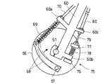
Next, another embodiment applied to the mechanical drum brake mechanism 65 will be described with reference to FIGS.
The
[0060]
A front wheel (not shown) is pivotally supported on the
[0061]
A disc-
A base end portion of a
[0062]
The end of the
[0063]
On the other hand, the swing fixing
[0064]
The end of the
[0065]
During normal running, the
[0066]
When the vehicle stops and the front wheels stop, the braking torque becomes substantially zero, and a part of the braking operation force that pulls the
[0067]
As described above, since the present embodiment also operates in the same manner as the above-described embodiment, the same effects can be achieved.
It can be applied to a complete mechanical drum brake mechanism 65 that does not use hydraulic pressure, and the structure of the rocking and fixing control mechanism as well as the braking mechanism is further simplified to achieve downsizing and cost reduction and highly reliable control. .
[0068]
In the above-described embodiment, the
[0069]
Further, the present invention is not limited to a vehicle in which a front vehicle body and a rear vehicle body are divided and connected to each other so as to be able to swing left and right, as well as a swing mechanism between a vehicle body and a power source, Therefore, the swing fixing mechanism can also be applied to a vehicle in various positions. Also, the two-wheeled vehicle having two swing mechanisms and the three-wheeled vehicle having two front wheels and one rear wheel and four It is also applied to automobiles with more than wheels.
[Brief description of the drawings]
FIG. 1 is a side view showing a schematic structure of a swing type three-wheeled vehicle according to an embodiment of the present invention.
FIG. 2 is a side view showing a swing mechanism and a swing fixing mechanism.
FIG. 3 is a side view showing a hydraulic disc brake mechanism and a swing fixing control mechanism.
FIG. 4 is a schematic diagram of a swing fixing control mechanism.
FIG. 5 is a schematic view of a swing fixing control mechanism applied to a hydraulic drum brake mechanism according to another embodiment.
FIG. 6 is a schematic diagram of a rocking and fixing control mechanism applied to a mechanical drum brake mechanism according to another embodiment.
FIG. 7 is a schematic view of another state.
[Explanation of symbols]
DESCRIPTION OF SYMBOLS 1 ... Swing type auto three-wheel vehicle, 2 ... Front vehicle body, 3 ... Rear vehicle body, 4 ... Front wheel, 5 ... Rear wheel, 6 ... Head pipe, 7 ... Body frame, 8 ... Connection bracket, 9 ... Pivot shaft, 10 ... Joint case, 11 ... Swing mechanism, 12 ... Bearing, 13 ... Knighthard mechanism, 14 ... Swing shaft, 15 ... Shock absorber, 16 ... Internal combustion engine, 17 ... Handle, 18 ... Front brake lever, 19 ... Front fork,
20 ... swing fixing mechanism, 21 ... swing lock plate, 22 ... pin, 23 ... locking member, 24 ... link member, 25 ... pin, 26 ... arm member, 27 ... swing fixing cable, 28 ... cable holder, 29 ... Cable outer,
30 ... Hydraulic disc brake mechanism, 31 ... Disc plate, 32 ... Brake caliper, 33 ... Brake hose,
40 ... Oscillation fixing control mechanism, 41 ... Caliper bracket, 42 ... Tension spring, 43 ... Secondary cylinder, 44 ... Support bracket, 45 ... Pin, 46 ... Stopper pin,
50 ... Hydraulic drum brake mechanism, 51 ... Brake panel, 52,53 ... Brake shoe, 54 ... Wheel cylinder, 55 ... Front axle, 56 ... Compression spring,
60 ... front fork, 61 ... front axle, 65 ... mechanical drum brake mechanism, 66 ... brake panel, 67 ... camshaft, 68 ... brake arm, 69 ... brake cable, 70 ... cable outer,
75 ... Oscillation fixing control mechanism, 76, 77 ... Torque receiving part, 78 ... Compression spring, 79 ... Oscillation fixing cable, 80 ... Cable outer.
Claims (4)
前記揺動機構の相対的揺動を規制する揺動固定機構と、
ブレーキ操作手段の操作により発生する制動操作力が作用することで前記前輪または後輪を制動する制動機構と、
車両が走行状態から停止状態になるまでは、前記ブレーキ操作手段の操作により発生する制動操作力を、前記前輪または後輪を制動する前記制動機構にのみに作用させ、車両が走行状態から停止状態になった後は、前記揺動固定機構にも前記ブレーキ操作手段の操作により発生している制動操作力の一部を作用させ前記揺動機構の相対的揺動を規制する揺動固定制御機構とを備えたことを特徴とする揺動式車両。In a rocking vehicle equipped with a rocking mechanism,
A swing fixing mechanism for restricting relative swing of the swing mechanism;
A braking mechanism for braking the front wheel or the rear wheel by applying a braking operation force generated by an operation of a brake operation means;
Until the vehicle is stopped from the running state, the braking operation force generated by the operation of the brake operating means is applied only to the braking mechanism that brakes the front wheel or the rear wheel, and the vehicle is stopped from the running state. After that, the swing fixing control mechanism that controls a relative swing of the swing mechanism by applying a part of the braking operation force generated by the operation of the brake operation means to the swing fixing mechanism. A rocking vehicle characterized by comprising:
前記揺動固定制御機構は、前記制動機構に作用する前記制動操作力の一部が前記機構保持部を車輪の前進回転方向と反対方向に付勢するよう構成され、制動された車輪が停止したとき前記制動操作力の一部が前記機構保持部を車輪の前進回転方向と反対方向に回動することで前記揺動固定機構を作動して前記揺動機構の揺動を規制することを特徴とする請求項1記載の揺動式車両。The brake mechanism is provided such that a mechanism holding portion that holds the operating portion is rotatable at a required small angle in the rotation direction of the wheel,
The swing fixing control mechanism is configured such that a part of the braking operation force acting on the braking mechanism biases the mechanism holding portion in a direction opposite to the forward rotation direction of the wheel, and the braked wheel is stopped. When a part of the braking operation force rotates the mechanism holding portion in a direction opposite to the forward rotation direction of the wheel, the swing fixing mechanism is operated to restrict swing of the swing mechanism. The rocking vehicle according to claim 1.
Priority Applications (6)
| Application Number | Priority Date | Filing Date | Title |
|---|---|---|---|
| JP2002157843A JP4132986B2 (en) | 2002-05-30 | 2002-05-30 | Swing type vehicle |
| IN450DE2003 IN2003DE00450A (en) | 2002-05-30 | 2003-03-27 | |
| DE60334347T DE60334347D1 (en) | 2002-05-30 | 2003-03-31 | Sideways inclinable vehicle |
| ES03007280T ES2351304T3 (en) | 2002-05-30 | 2003-03-31 | OSCILATION TYPE VEHICLE. |
| EP03007280A EP1366973B1 (en) | 2002-05-30 | 2003-03-31 | Oscillation type vehicle |
| CNB031084311A CN1305730C (en) | 2002-05-30 | 2003-03-31 | Shaking vehicle |
Applications Claiming Priority (1)
| Application Number | Priority Date | Filing Date | Title |
|---|---|---|---|
| JP2002157843A JP4132986B2 (en) | 2002-05-30 | 2002-05-30 | Swing type vehicle |
Publications (2)
| Publication Number | Publication Date |
|---|---|
| JP2003341577A JP2003341577A (en) | 2003-12-03 |
| JP4132986B2 true JP4132986B2 (en) | 2008-08-13 |
Family
ID=29417233
Family Applications (1)
| Application Number | Title | Priority Date | Filing Date |
|---|---|---|---|
| JP2002157843A Expired - Lifetime JP4132986B2 (en) | 2002-05-30 | 2002-05-30 | Swing type vehicle |
Country Status (6)
| Country | Link |
|---|---|
| EP (1) | EP1366973B1 (en) |
| JP (1) | JP4132986B2 (en) |
| CN (1) | CN1305730C (en) |
| DE (1) | DE60334347D1 (en) |
| ES (1) | ES2351304T3 (en) |
| IN (1) | IN2003DE00450A (en) |
Families Citing this family (5)
| Publication number | Priority date | Publication date | Assignee | Title |
|---|---|---|---|---|
| JP4590197B2 (en) * | 2004-03-01 | 2010-12-01 | 本田技研工業株式会社 | Motorcycle brake equipment |
| JP4648790B2 (en) * | 2005-07-29 | 2011-03-09 | 本田技研工業株式会社 | Exhaust device for small vehicles |
| JP2011057018A (en) | 2009-09-08 | 2011-03-24 | Yamaha Motor Co Ltd | Saddle-riding type vehicle |
| US8746717B2 (en) | 2009-12-17 | 2014-06-10 | Yamaha Hatsudoki Kabushiki Kaisha | Saddle riding type vehicle |
| CN102442391B (en) * | 2010-10-14 | 2016-06-08 | 光阳工业股份有限公司 | Parking structure of electric tricycle |
Family Cites Families (7)
| Publication number | Priority date | Publication date | Assignee | Title |
|---|---|---|---|---|
| JPS5529604A (en) * | 1978-08-17 | 1980-03-03 | Yamaha Motor Co Ltd | Automatic threeewheeler |
| JPS55144190U (en) * | 1979-04-05 | 1980-10-16 | ||
| JPS5812873A (en) * | 1981-07-14 | 1983-01-25 | 本田技研工業株式会社 | Rolling lock device for rocking tricycle |
| JPS59120586A (en) * | 1982-12-28 | 1984-07-12 | ヤマハ発動機株式会社 | Oscillation controller for oscillation type car |
| JPS6132196A (en) | 1984-07-23 | 1986-02-14 | オムロン株式会社 | Excess bathing alarm |
| JPS6345361A (en) | 1986-08-11 | 1988-02-26 | Matsushita Electric Ind Co Ltd | Production of thin phthalocyanine film |
| CN2382631Y (en) * | 1999-08-03 | 2000-06-14 | 雷乾均 | Foot tricycle |
-
2002
- 2002-05-30 JP JP2002157843A patent/JP4132986B2/en not_active Expired - Lifetime
-
2003
- 2003-03-27 IN IN450DE2003 patent/IN2003DE00450A/en unknown
- 2003-03-31 EP EP03007280A patent/EP1366973B1/en not_active Expired - Lifetime
- 2003-03-31 CN CNB031084311A patent/CN1305730C/en not_active Expired - Fee Related
- 2003-03-31 DE DE60334347T patent/DE60334347D1/en not_active Expired - Lifetime
- 2003-03-31 ES ES03007280T patent/ES2351304T3/en not_active Expired - Lifetime
Also Published As
| Publication number | Publication date |
|---|---|
| EP1366973B1 (en) | 2010-09-29 |
| CN1305730C (en) | 2007-03-21 |
| EP1366973A3 (en) | 2004-04-21 |
| CN1462706A (en) | 2003-12-24 |
| IN2003DE00450A (en) | 2015-05-01 |
| JP2003341577A (en) | 2003-12-03 |
| EP1366973A2 (en) | 2003-12-03 |
| ES2351304T3 (en) | 2011-02-02 |
| DE60334347D1 (en) | 2010-11-11 |
Similar Documents
| Publication | Publication Date | Title |
|---|---|---|
| JP2003072528A (en) | Riding mower | |
| JP4098909B2 (en) | Work vehicle speed canceling device | |
| JP4132986B2 (en) | Swing type vehicle | |
| US20010020377A1 (en) | Parking brake device for vehicle | |
| JP3790025B2 (en) | Brake device for motorcycle | |
| JP2007055281A (en) | Travel speed operation device | |
| JP4040763B2 (en) | Brake equipment for motorcycles | |
| JP3573896B2 (en) | Brake equipment for motorcycles | |
| JP2004042813A (en) | Brake unit of forklift | |
| JP2006076535A (en) | Brake device | |
| JP2699186B2 (en) | Brake operating device with grip brake | |
| JP7646716B2 (en) | Saddle-type vehicle | |
| JPS644632Y2 (en) | ||
| JPS625984Y2 (en) | ||
| JPS62166123A (en) | Hill holder device for automobile | |
| JPH10167032A (en) | Vehicular brake device | |
| JP3892123B2 (en) | Brake equipment for motorcycles | |
| KR200220801Y1 (en) | Integral Pedal Unit for Vehicles | |
| JP2007302036A (en) | Brake system | |
| JP2023136198A (en) | vehicle | |
| JPS603002Y2 (en) | Hydraulic pressure holding device for automobile brakes | |
| JPS6221475Y2 (en) | ||
| JPS6210211Y2 (en) | ||
| JPH0439115Y2 (en) | ||
| JPH11189189A (en) | Motorcycle parking brake device |
Legal Events
| Date | Code | Title | Description |
|---|---|---|---|
| A621 | Written request for application examination |
Free format text: JAPANESE INTERMEDIATE CODE: A621 Effective date: 20041202 |
|
| A131 | Notification of reasons for refusal |
Free format text: JAPANESE INTERMEDIATE CODE: A131 Effective date: 20060614 |
|
| A977 | Report on retrieval |
Free format text: JAPANESE INTERMEDIATE CODE: A971007 Effective date: 20060616 |
|
| A521 | Request for written amendment filed |
Free format text: JAPANESE INTERMEDIATE CODE: A523 Effective date: 20060807 |
|
| A131 | Notification of reasons for refusal |
Free format text: JAPANESE INTERMEDIATE CODE: A131 Effective date: 20070313 |
|
| A521 | Request for written amendment filed |
Free format text: JAPANESE INTERMEDIATE CODE: A523 Effective date: 20070510 |
|
| A02 | Decision of refusal |
Free format text: JAPANESE INTERMEDIATE CODE: A02 Effective date: 20080109 |
|
| A521 | Request for written amendment filed |
Free format text: JAPANESE INTERMEDIATE CODE: A523 Effective date: 20080207 |
|
| A911 | Transfer to examiner for re-examination before appeal (zenchi) |
Free format text: JAPANESE INTERMEDIATE CODE: A911 Effective date: 20080314 |
|
| A131 | Notification of reasons for refusal |
Free format text: JAPANESE INTERMEDIATE CODE: A131 Effective date: 20080408 |
|
| A521 | Request for written amendment filed |
Free format text: JAPANESE INTERMEDIATE CODE: A523 Effective date: 20080414 |
|
| TRDD | Decision of grant or rejection written | ||
| A01 | Written decision to grant a patent or to grant a registration (utility model) |
Free format text: JAPANESE INTERMEDIATE CODE: A01 Effective date: 20080513 |
|
| A01 | Written decision to grant a patent or to grant a registration (utility model) |
Free format text: JAPANESE INTERMEDIATE CODE: A01 |
|
| A61 | First payment of annual fees (during grant procedure) |
Free format text: JAPANESE INTERMEDIATE CODE: A61 Effective date: 20080602 |
|
| FPAY | Renewal fee payment (event date is renewal date of database) |
Free format text: PAYMENT UNTIL: 20110606 Year of fee payment: 3 |
|
| R150 | Certificate of patent or registration of utility model |
Ref document number: 4132986 Country of ref document: JP Free format text: JAPANESE INTERMEDIATE CODE: R150 Free format text: JAPANESE INTERMEDIATE CODE: R150 |
|
| FPAY | Renewal fee payment (event date is renewal date of database) |
Free format text: PAYMENT UNTIL: 20110606 Year of fee payment: 3 |
|
| FPAY | Renewal fee payment (event date is renewal date of database) |
Free format text: PAYMENT UNTIL: 20130606 Year of fee payment: 5 |
|
| FPAY | Renewal fee payment (event date is renewal date of database) |
Free format text: PAYMENT UNTIL: 20130606 Year of fee payment: 5 |
|
| FPAY | Renewal fee payment (event date is renewal date of database) |
Free format text: PAYMENT UNTIL: 20140606 Year of fee payment: 6 |
|
| EXPY | Cancellation because of completion of term |