JP4131990B2 - Pressure sensor compensates for zero shift nonlinearity at ultra-low temperatures - Google Patents
Pressure sensor compensates for zero shift nonlinearity at ultra-low temperatures Download PDFInfo
- Publication number
- JP4131990B2 JP4131990B2 JP54786099A JP54786099A JP4131990B2 JP 4131990 B2 JP4131990 B2 JP 4131990B2 JP 54786099 A JP54786099 A JP 54786099A JP 54786099 A JP54786099 A JP 54786099A JP 4131990 B2 JP4131990 B2 JP 4131990B2
- Authority
- JP
- Japan
- Prior art keywords
- resistance
- pressure sensor
- temperature
- bridge
- parallel
- Prior art date
- Legal status (The legal status is an assumption and is not a legal conclusion. Google has not performed a legal analysis and makes no representation as to the accuracy of the status listed.)
- Expired - Lifetime
Links
- 230000007423 decrease Effects 0.000 claims description 16
- BASFCYQUMIYNBI-UHFFFAOYSA-N platinum Chemical compound [Pt] BASFCYQUMIYNBI-UHFFFAOYSA-N 0.000 claims description 10
- 239000000758 substrate Substances 0.000 claims description 7
- 229910052697 platinum Inorganic materials 0.000 claims description 5
- PCHJSUWPFVWCPO-UHFFFAOYSA-N gold Chemical compound [Au] PCHJSUWPFVWCPO-UHFFFAOYSA-N 0.000 claims description 4
- 239000010931 gold Substances 0.000 claims description 4
- 229910052737 gold Inorganic materials 0.000 claims description 4
- 229910052751 metal Inorganic materials 0.000 claims description 3
- 239000002184 metal Substances 0.000 claims description 3
- 239000000523 sample Substances 0.000 description 10
- IJGRMHOSHXDMSA-UHFFFAOYSA-N Atomic nitrogen Chemical compound N#N IJGRMHOSHXDMSA-UHFFFAOYSA-N 0.000 description 6
- 239000010409 thin film Substances 0.000 description 4
- 229910018487 Ni—Cr Inorganic materials 0.000 description 3
- 238000009835 boiling Methods 0.000 description 3
- VNNRSPGTAMTISX-UHFFFAOYSA-N chromium nickel Chemical compound [Cr].[Ni] VNNRSPGTAMTISX-UHFFFAOYSA-N 0.000 description 3
- 229910052757 nitrogen Inorganic materials 0.000 description 3
- XUIMIQQOPSSXEZ-UHFFFAOYSA-N Silicon Chemical compound [Si] XUIMIQQOPSSXEZ-UHFFFAOYSA-N 0.000 description 2
- 238000010586 diagram Methods 0.000 description 2
- 238000005259 measurement Methods 0.000 description 2
- 229910052710 silicon Inorganic materials 0.000 description 2
- 239000010703 silicon Substances 0.000 description 2
- 230000002411 adverse Effects 0.000 description 1
- 230000003247 decreasing effect Effects 0.000 description 1
- 238000000151 deposition Methods 0.000 description 1
- 238000000034 method Methods 0.000 description 1
- 230000035945 sensitivity Effects 0.000 description 1
- 238000004544 sputter deposition Methods 0.000 description 1
Images

Classifications
-
- G—PHYSICS
- G01—MEASURING; TESTING
- G01L—MEASURING FORCE, STRESS, TORQUE, WORK, MECHANICAL POWER, MECHANICAL EFFICIENCY, OR FLUID PRESSURE
- G01L1/00—Measuring force or stress, in general
- G01L1/20—Measuring force or stress, in general by measuring variations in ohmic resistance of solid materials or of electrically-conductive fluids; by making use of electrokinetic cells, i.e. liquid-containing cells wherein an electrical potential is produced or varied upon the application of stress
- G01L1/22—Measuring force or stress, in general by measuring variations in ohmic resistance of solid materials or of electrically-conductive fluids; by making use of electrokinetic cells, i.e. liquid-containing cells wherein an electrical potential is produced or varied upon the application of stress using resistance strain gauges
- G01L1/2268—Arrangements for correcting or for compensating unwanted effects
- G01L1/2281—Arrangements for correcting or for compensating unwanted effects for temperature variations
-
- G—PHYSICS
- G01—MEASURING; TESTING
- G01L—MEASURING FORCE, STRESS, TORQUE, WORK, MECHANICAL POWER, MECHANICAL EFFICIENCY, OR FLUID PRESSURE
- G01L9/00—Measuring steady of quasi-steady pressure of fluid or fluent solid material by electric or magnetic pressure-sensitive elements; Transmitting or indicating the displacement of mechanical pressure-sensitive elements, used to measure the steady or quasi-steady pressure of a fluid or fluent solid material, by electric or magnetic means
- G01L9/02—Measuring steady of quasi-steady pressure of fluid or fluent solid material by electric or magnetic pressure-sensitive elements; Transmitting or indicating the displacement of mechanical pressure-sensitive elements, used to measure the steady or quasi-steady pressure of a fluid or fluent solid material, by electric or magnetic means by making use of variations in ohmic resistance, e.g. of potentiometers, electric circuits therefor, e.g. bridges, amplifiers or signal conditioning
- G01L9/04—Measuring steady of quasi-steady pressure of fluid or fluent solid material by electric or magnetic pressure-sensitive elements; Transmitting or indicating the displacement of mechanical pressure-sensitive elements, used to measure the steady or quasi-steady pressure of a fluid or fluent solid material, by electric or magnetic means by making use of variations in ohmic resistance, e.g. of potentiometers, electric circuits therefor, e.g. bridges, amplifiers or signal conditioning of resistance-strain gauges
- G01L9/045—Measuring steady of quasi-steady pressure of fluid or fluent solid material by electric or magnetic pressure-sensitive elements; Transmitting or indicating the displacement of mechanical pressure-sensitive elements, used to measure the steady or quasi-steady pressure of a fluid or fluent solid material, by electric or magnetic means by making use of variations in ohmic resistance, e.g. of potentiometers, electric circuits therefor, e.g. bridges, amplifiers or signal conditioning of resistance-strain gauges with electric temperature compensating means
Landscapes
- Physics & Mathematics (AREA)
- General Physics & Mathematics (AREA)
- Measuring Fluid Pressure (AREA)
- Measurement Of Force In General (AREA)
- Measurement Of Length, Angles, Or The Like Using Electric Or Magnetic Means (AREA)
Description
発明の分野
本発明は、ホイートストンブリッジのそれぞれのアームに取り付けられた歪ゲージを有する種類の圧力センサに関する。
発明が特に関係する分野は、超低温、特に窒素の沸点以下の温度で、できれば数ケルビンまで低下した温度で使用可能な圧力センサの分野である。
発明の背景
ホイートストンブリッジとして接続された歪ゲージ圧力センサによく知られた問題は、温度の関数としてのブリッジドリフトの零点の問題である。
この問題を解決するために、ブリッジの入力及び/又は出力に接続された補償ネットワークが一般に使用されている。歪ゲージブリッジの温度ドリフトが通常の温度範囲にわたって実質的に線形である場合には、少なくとも一つの感温素子を有するネットワークが線形補償のために設計されるのが一般的である。
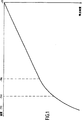
圧力センサが超低温で使用される場合、別の問題が発生する。歪ゲージブリッジの温度ドリフトは非線形となり、非線形性は温度が下がるにつれて増大する。このことが図1に示されていて、シリコン基板上の薄膜ニッケル−クロム層からなる歪ゲージブリッジからの出力電圧は温度の関数として変化し、ブリッジは22℃の温度で平衡状態(0の出力電圧)にある。
一般的に使用されるサーミスタは、温度が−40℃あるいは−50℃以下に低下すると、非常に高く、実質的に無限大になる抵抗を持っていることから、通常の補償ネットワークは役に立たなくなる。
本発明が解決しようとする問題は、温度ドリフトの非線形性の問題であり、超低温、特に窒素の沸点すなわち約−196℃以下の温度でそのようなドリフトを「線形化する」問題である。
発明の概要
この問題は、ブリッジのアームの少なくとも一つの歪ゲージを、歪ゲージよりも抵抗がかなり小さく補償回路と並列に接続された抵抗器と直列に配設し、補償回路は、超低温域においてそれと並列に接続された抵抗器の抵抗に影響を及ぼし、温度が低下するにつれて増大するように温度の関数として抵抗が変化する抵抗素子を有する圧力センサにより解決される。
並列に接続された補償回路を有する抵抗器は、ブリッジの作動範囲及び感度に不利な影響を与えないように歪ゲージよりもかなり小さい抵抗を有している。本願明細書において、別の抵抗より「かなり小さい」抵抗とは、歪ゲージの抵抗の1/20あるいは1/100あるいはそれより小さいことを意味している。
本発明の圧力センサの特徴は、補償回路が、歪ゲージをブリッジのコーナーの一つに接続する接続リードにより形成された抵抗器と並列に接続されていることである。
したがって、補償回路を接続するためにブリッジを修正する必要がなく、この目的のためにブリッジを開放した場合に発生する不安定さを解消することができる。
さらに、非線形性を補償する回路は、ブリッジにかなり接近して配置することができ、ブリッジと全く同じ温度状態にすることができる。
歪ゲージと、歪ゲージをブリッジのコーナーに接続する接続リードとは、好ましくは、基板上の金属の付着層により構成される。
超低温域、例えば−196℃以下で非線形性を補償するために、補償回路の抵抗素子は、並列に接続された抵抗器の抵抗に影響を与え、温度低下とともに増大するような抵抗を有している。この目的のため、抵抗素子が並列に接続された抵抗器の抵抗に対する抵抗素子の抵抗の割合が、温度が−196℃以下に低下すると、100よりも小さく、その後温度の低下とともに減少するのがよい。例えば、そのような抵抗素子は、プラチナプローブにより構成することができる。
【図面の簡単な説明】
添付図面において、
図1は、歪ゲージブリッジにより構成される圧力センサの零ドリフトが、ドリフト補償がない場合、温度の関数としてどのように変化するかを示している。
図2は、本発明の圧力センサの実施例の電気回路図である。
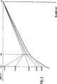
図3は、本発明に基づいて非線形温度ドリフトを補償する回路が取り付けられた図1の圧力センサの零ドリフトが温度の関数としてどのように変化するかを示している。
好ましい実施例の詳細説明
図2は、ホイートストンブリッジ10の四つのアームのそれぞれに挿入された四つの歪ゲージJ1,J2,J3,J4を有する圧力センサの回路図である。歪ゲージJ1〜J4の各々は、ブリッジの隣接する二つのコーナーに接続リードcにより接続されている。
歪ゲージJ1〜J4及び接続リードcは、センサの感知素子の一部を形成する基板、例えばシリコン基板上の金属層によりすべて形成される。周知の方法では、ブリッジの反対側の二つのアームの二つの歪ゲージは、基板が計測時に圧力を受けると伸びるように基板上に設けられる一方、他の二つの歪ゲージは圧縮するように設けられる。
一例として、歪ゲージJ1〜J4は、できるだけ同一のニッケル−クロム層により構成される一方、接続リードcは、例えば同様にできるだけ同一の金の付着層によって構成される。
付着層は、例えば真空スパッタリングにより薄膜として形成され、ブリッジは形成された付着層により閉止される。
ブリッジの反対側の二つのコーナー+a、−aは給電端子+A、−Aに接続される一方、他の二つのコーナー+m、−mは、計測用端子+M、−Mに接続される。介装された補償ネットワーク12は、その片側でコーナー+a、−a、+m、−mに接続され、その反対側で端子+A、−A、+M、−Mに接続されている。補償ネットワーク12は、圧力センサの線形ドリフトを温度の関数として補償するためのものである。これは、例えば公報FR−A2613833に記載のような従来型の抵抗ネットワークにより構成されている。
ブリッジの非線形零ドリフトを補償する回路20は、ブリッジの歪ゲージの一つ、例えば歪ゲージJ2を、歪ゲージを含むアームの端部に位置するブリッジの二つのコーナーの一つ、例えばコーナー+mに接続する接続リードcの一つと並列に接続されている。
補償回路20は、特に超低温の範囲、例えば窒素の沸点(−196℃)より低い温度において、抵抗が温度の関数として変化する抵抗素子Pを備えている。補償回路内で、調整可能な抵抗器Rを抵抗素子Pと直列に接続することもでき、結果として補償を調整することができる。
ブリッジのアームの一つの全抵抗の一部と抵抗素子を並列に接続することにより、ブリッジの挙動に非線形の影響を与えることができ、その非線形ドリフトを補償することができる。この非線形性が温度の低下とともに増大すると、抵抗素子Pの影響は増大、すなわち、その抵抗は減少する必要があり、温度が−196℃以下に低下すると、その抵抗の接続リードcの抵抗に対する割合は100よりも小さくなり、温度が−196℃以下に下がり続けるにつれて減少する。このような状況では、温度係数が正の抵抗素子Pが使用され、例えばプラチナプローブを使用することができる。
ニッケル−クロムの薄膜を付着させることにより形成され、各歪ゲージの抵抗が周囲温度(22℃)で1000Ωである歪ゲージを使用して、図2に示されるような圧力センサを作製した。接続リードcは、金の線形薄膜付着層で、各々22℃で0.6Ωの抵抗を有している。
図1は、センサにどんな応力も加わらず、補償ネットワーク12及び補償回路20がない場合に、ブリッジのコーナー+m、−m間に生じた電圧がどのように変化するかを示しており、ブリッジは22℃で平衡状態(0の出力電圧)にある。
歪ゲージに主に起因するブリッジの零ドリフトは、温度が下がるにつれてますます顕著になることがわかる。約−140℃までは、ドリフトは実質的に線形である。より低い温度では、ドリフトの非線形性はますます明確になる。
調整可能な抵抗器Rと直列に接続され、0℃で100Ωに等しい抵抗のプラチナプローブPにより構成される補償回路は、歪ゲージJ2をブリッジのコーナー+mに接続する金の接続リードに並列に接続される。
下の表1は、接続リードcとプローブPの抵抗を示しており、調整可能な抵抗器Rは0である。これはまた、様々な異なる温度において、P及びcにより形成される並列回路の等価抵抗を示している。プローブPの抵抗の接続リードcの抵抗に対する割合は、−196℃から−246℃の範囲で約47から約7.9まで変化する。

補償回路20がない場合の零ドリフトの変化を示す曲線Iに比べて、非線形補正は、抵抗器Rの抵抗が減少するとともに、ますます強調されている。この例では、R=4Ωで、二つのプローブPが並列の場合、ブリッジの零ドリフトは、超低温(約−250℃)まで線形化されている。線形補償ネットワーク12の作用により、周囲温度から超低温(数ケルビン)までの全域にわたって、ブリッジの温度ドリフトを零に完全に補償することができる。
上記において、非線形ドリフトを補償する回路は、ブリッジのアームの一つにある歪ゲージをブリッジのコーナーに接続する接続リードの一つに並列に接続されていると記載したが、同じ効果が、ブリッジのこのアームの接続リードの一つ及び/又は両方と並列に、及び/又は、反対側のアームの接続リードの一つ及び/又は両方に並列に非線形ドリフト補償回路を接続することにより達成される。
図1において、非線形性は、ドリフトの線形成分と同じ方向で悪化するように変化しているが、非線形性は反対方向に変化することもある。この変化の方向により、補償回路は、ブリッジの反対側のアームの第1の対の一つあるいは両方に、あるいは、ブリッジの反対側の他の二つのアームの一つ及び/又は両方に接続すべきである。The present invention relates to a type of pressure sensor having a strain gauge attached to each arm of a Wheatstone bridge.
The field in which the invention is particularly relevant is that of pressure sensors which can be used at ultra-low temperatures, in particular at temperatures below the boiling point of nitrogen, preferably as low as several Kelvin.
BACKGROUND OF THE INVENTION A well-known problem with strain gauge pressure sensors connected as a Wheatstone bridge is the problem of bridge drift zeros as a function of temperature.
In order to solve this problem, a compensation network connected to the input and / or output of the bridge is commonly used. If the strain gauge bridge temperature drift is substantially linear over the normal temperature range, a network with at least one temperature sensitive element is typically designed for linear compensation.
Another problem arises when pressure sensors are used at very low temperatures. The temperature drift of the strain gauge bridge becomes non-linear and the non-linearity increases as the temperature decreases. This is illustrated in FIG. 1, where the output voltage from a strain gauge bridge consisting of a thin film nickel-chromium layer on a silicon substrate varies as a function of temperature, and the bridge is in an equilibrium state (zero output at a temperature of 22 ° C. Voltage).
Commonly used thermistors have a resistance that becomes very high and substantially infinite when the temperature drops below -40 ° C. or below -50 ° C., so the normal compensation network becomes useless.
The problem to be solved by the present invention is the problem of nonlinearity of temperature drift, the problem of “linearizing” such drift at ultra-low temperatures, especially at the boiling point of nitrogen, ie, temperatures below about −196 ° C.
SUMMARY OF THE INVENTION The problem is that at least one strain gauge of the arm of the bridge is placed in series with a resistor that is much smaller in resistance than the strain gauge and connected in parallel with the compensation circuit. It is solved by a pressure sensor having a resistive element that affects the resistance of a resistor connected in parallel with it and whose resistance changes as a function of temperature so that it increases as the temperature decreases.
A resistor having a compensation circuit connected in parallel has a much smaller resistance than the strain gauge so as not to adversely affect the operating range and sensitivity of the bridge. In this specification, a resistance that is “substantially less than” another resistance means that it is 1/20 or 1/100 or less of the resistance of the strain gauge.
A feature of the pressure sensor of the present invention is that the compensation circuit is connected in parallel with a resistor formed by a connection lead connecting the strain gauge to one of the corners of the bridge.
Therefore, it is not necessary to modify the bridge to connect the compensation circuit, and instability that occurs when the bridge is opened for this purpose can be eliminated.
Furthermore, the circuit that compensates for the non-linearity can be placed quite close to the bridge and can be in exactly the same temperature state as the bridge.
The strain gauge and the connecting lead connecting the strain gauge to the corner of the bridge are preferably constituted by a metal adhesion layer on the substrate.
In order to compensate for non-linearity in an ultra-low temperature range, for example, −196 ° C. or less, the resistance element of the compensation circuit has a resistance that affects the resistance of the resistors connected in parallel and increases as the temperature decreases. Yes. For this purpose, the ratio of the resistance of the resistance element to the resistance of the resistor having the resistance element connected in parallel is smaller than 100 when the temperature is lowered to −196 ° C. or less, and then decreases with a decrease in temperature. Good. For example, such a resistance element can be constituted by a platinum probe.
[Brief description of the drawings]
In the accompanying drawings,
FIG. 1 shows how the zero drift of a pressure sensor composed of a strain gauge bridge changes as a function of temperature in the absence of drift compensation.
FIG. 2 is an electric circuit diagram of an embodiment of the pressure sensor of the present invention.
FIG. 3 illustrates how the zero drift of the pressure sensor of FIG. 1 fitted with circuitry to compensate for non-linear temperature drift according to the present invention varies as a function of temperature.
Detailed Description of the Preferred Embodiment FIG. 2 is a circuit diagram of a pressure sensor having four strain gauges J1, J2, J3, J4 inserted into each of the four arms of the Wheatstone
The strain gauges J1 to J4 and the connection leads c are all formed by a metal layer on a substrate that forms part of the sensing element of the sensor, for example, a silicon substrate. In a known method, two strain gauges on the two arms on the opposite side of the bridge are provided on the substrate so that they stretch when the substrate is subjected to pressure during measurement, while the other two strain gauges are provided to compress. It is done.
As an example, the strain gauges J1 to J4 are composed of the same nickel-chromium layer as much as possible, while the connection lead c is composed of the same gold adhesion layer as much as possible.
The adhesion layer is formed as a thin film by, for example, vacuum sputtering, and the bridge is closed by the formed adhesion layer.
The two corners + a and -a on the opposite side of the bridge are connected to the power supply terminals + A and -A, while the other two corners + m and -m are connected to the measurement terminals + M and -M. The intervening
The
The
By connecting a part of the total resistance of one of the arms of the bridge and the resistance element in parallel, the behavior of the bridge can be influenced nonlinearly, and the nonlinear drift can be compensated. When this non-linearity increases with a decrease in temperature, the influence of the resistance element P increases, that is, the resistance needs to decrease. When the temperature decreases to −196 ° C. or less, the ratio of the resistance to the resistance of the connection lead c Becomes less than 100 and decreases as the temperature continues to drop below -196 ° C. In such a situation, a resistance element P having a positive temperature coefficient is used, and for example, a platinum probe can be used.
A pressure sensor as shown in FIG. 2 was produced using a strain gauge formed by depositing a nickel-chromium thin film and having a resistance of 1000Ω at each ambient temperature (22 ° C.). The connecting leads c are gold linear thin film adhesion layers, each having a resistance of 0.6Ω at 22 ° C.
FIG. 1 shows how the voltage generated between the corners of the bridge + m, −m changes in the absence of any stress on the sensor and without the
It can be seen that the zero drift of the bridge, mainly due to the strain gauge, becomes more pronounced as the temperature decreases. Up to about −140 ° C., the drift is substantially linear. At lower temperatures, drift nonlinearity becomes increasingly clear.
A compensation circuit consisting of a platinum probe P connected in series with an adjustable resistor R and having a resistance equal to 100Ω at 0 ° C. is connected in parallel to the gold connection lead connecting the strain gauge J2 to the corner + m of the bridge. Is done.
Table 1 below shows the resistance of the connection lead c and the probe P, and the adjustable resistor R is zero. This also shows the equivalent resistance of the parallel circuit formed by P and c at various different temperatures. The ratio of the resistance of the probe P to the resistance of the connection lead c varies from about 47 to about 7.9 in the range of −196 ° C. to −246 ° C.
Compared to curve I, which shows the change in zero drift in the absence of
In the above, the circuit that compensates for non-linear drift is described as being connected in parallel to one of the connection leads connecting the strain gauge in one of the arms of the bridge to the corner of the bridge. Achieved by connecting a non-linear drift compensation circuit in parallel with one and / or both of the connecting leads of this arm and / or in parallel with one and / or both of the connecting leads of the opposite arm. .
In FIG. 1, the non-linearity changes to worsen in the same direction as the linear component of drift, but the non-linearity may change in the opposite direction. Depending on the direction of this change, the compensation circuit connects to one or both of the first pair of arms on the opposite side of the bridge, or to one and / or both of the other two arms on the other side of the bridge. Should.
Claims (5)
上記温度域において上記ホイートストンブリッジ(10)の非線形零ドリフトを補償する補償回路をさらに備え、該補償回路は、上記ホイートストンブリッジ(10)の一つのコーナーと上記歪ゲージ(J1〜J4)の一つの間の上記接続リード(c)と並列に接続された抵抗素子(P)を有し、該抵抗素子(P)の抵抗は上記歪ゲージ(J1〜J4)の抵抗の1/20より小さく、上記温度域において、並列に接続された上記接続リード(c)の抵抗に影響を及ぼすように温度の関数として変化し、その影響力は温度が低下するにつれて増大することを特徴とする圧力センサ。Strain gauges (J1 to J4) attached to respective arms of the Wheatstone bridge (10), and connection leads (c) for connecting the strain gauges to two adjacent corners of the Wheatstone bridge (10), The strain gauges (J1 to J4) and connection leads (c) are formed of a metal layer on a substrate, and are pressure sensors used in a temperature range of −196 ° C. or less,
The compensation circuit further compensates for the nonlinear zero drift of the Wheatstone bridge (10) in the temperature range, and the compensation circuit includes one corner of the Wheatstone bridge (10) and one of the strain gauges (J1 to J4). A resistance element (P) connected in parallel with the connection lead (c) between, the resistance of the resistance element (P) is smaller than 1/20 of the resistance of the strain gauge (J1 to J4), In the temperature range, the pressure sensor changes as a function of temperature so as to affect the resistance of the connecting lead (c) connected in parallel, and the influence thereof increases as the temperature decreases .
Applications Claiming Priority (3)
| Application Number | Priority Date | Filing Date | Title |
|---|---|---|---|
| FR98/03437 | 1998-03-20 | ||
| FR9803437A FR2776384B1 (en) | 1998-03-20 | 1998-03-20 | PRESSURE SENSOR WITH COMPENSATION FOR THE NON-LINEARITY OF THE ZERO DRIFT AT VERY LOW TEMPERATURES |
| PCT/FR1999/000637 WO1999049288A1 (en) | 1998-03-20 | 1999-03-19 | Pressure sensor with compensation for null shift non-linearity at very low temperatures |
Publications (3)
| Publication Number | Publication Date |
|---|---|
| JP2001527652A JP2001527652A (en) | 2001-12-25 |
| JP2001527652A5 JP2001527652A5 (en) | 2007-03-22 |
| JP4131990B2 true JP4131990B2 (en) | 2008-08-13 |
Family
ID=9524275
Family Applications (1)
| Application Number | Title | Priority Date | Filing Date |
|---|---|---|---|
| JP54786099A Expired - Lifetime JP4131990B2 (en) | 1998-03-20 | 1999-03-19 | Pressure sensor compensates for zero shift nonlinearity at ultra-low temperatures |
Country Status (8)
| Country | Link |
|---|---|
| US (1) | US6314815B1 (en) |
| EP (1) | EP0990128B1 (en) |
| JP (1) | JP4131990B2 (en) |
| CN (1) | CN1144032C (en) |
| DE (1) | DE69926847T2 (en) |
| ES (1) | ES2246565T3 (en) |
| FR (1) | FR2776384B1 (en) |
| WO (1) | WO1999049288A1 (en) |
Families Citing this family (16)
| Publication number | Priority date | Publication date | Assignee | Title |
|---|---|---|---|---|
| US6701790B2 (en) * | 2002-06-13 | 2004-03-09 | Mykrolis Corporation | Temperature regulator for use with a pressure sensing device |
| CN101275876B (en) * | 2007-03-27 | 2011-05-11 | 豪威国际控股有限公司 | Design method of bridge arm balance compensating resistance of pressure sensor signal conditioning integrate circuit |
| JP5066010B2 (en) * | 2008-06-09 | 2012-11-07 | 株式会社タニタ | Multi-point scale and manufacturing method thereof |
| US7938016B2 (en) * | 2009-03-20 | 2011-05-10 | Freescale Semiconductor, Inc. | Multiple layer strain gauge |
| CN101887081B (en) * | 2010-06-29 | 2012-09-05 | 三一重工股份有限公司 | Bridge zero adjustment circuit |
| CN102252700B (en) * | 2011-04-29 | 2012-08-22 | 中北大学 | Micro-cantilever beam piezoresistive bridge type sensor detecting instrument |
| JP6490039B2 (en) * | 2016-10-21 | 2019-03-27 | ミネベアミツミ株式会社 | Strain gauge |
| CN106595832B (en) * | 2016-12-07 | 2023-05-02 | 锐马(福建)电气制造有限公司 | A load cell zero drift compensation workbench |
| CN106802170B (en) * | 2016-12-30 | 2019-07-19 | 北京七星华创流量计有限公司 | Flow sensor, mass flow conveying measure and control device and its temperature drift suppressing method |
| CN110823446B (en) * | 2019-10-18 | 2022-01-07 | 成都凯天电子股份有限公司 | Secondary temperature compensation zero debugging method for silicon piezoresistive pressure sensor |
| US12535371B2 (en) * | 2020-09-18 | 2026-01-27 | Shenzhen New Degree Technology Co., Ltd. | Temperature and pressure sensors with different temperature coefficients of resistance and electronic device |
| CN113639903A (en) * | 2021-07-13 | 2021-11-12 | 西安理工大学 | Stress detection method in FDM printing process |
| CN117716219A (en) * | 2022-06-29 | 2024-03-15 | 株式会社斯巴鲁 | Force measuring element and output adjusting method thereof |
| CN115342961B (en) * | 2022-08-12 | 2025-07-22 | 江阴市埃夫隆电子科技有限公司 | Temperature drift suppression circuit of bridge type sensor of silk thread tension meter |
| CN117030098B (en) * | 2023-09-28 | 2024-02-27 | 无锡菲欧科技有限公司 | Double-pressure output sensor with temperature compensation |
| CN118518319A (en) * | 2024-07-24 | 2024-08-20 | 中国空气动力研究与发展中心超高速空气动力研究所 | Compensation resistor resistance value adjusting method |
Family Cites Families (8)
| Publication number | Priority date | Publication date | Assignee | Title |
|---|---|---|---|---|
| US3645136A (en) * | 1970-04-15 | 1972-02-29 | Charles W Calhoun | Fluid pressure measuring device |
| JPS55163880A (en) * | 1979-06-07 | 1980-12-20 | Hitachi Ltd | Semiconductor strain gauge bridge circuit |
| US4333349A (en) * | 1980-10-06 | 1982-06-08 | Kulite Semiconductor Products, Inc. | Binary balancing apparatus for semiconductor transducer structures |
| FR2497346A1 (en) * | 1980-12-31 | 1982-07-02 | Gi Teploene | Semiconductor extension transducer - has monocrystalline substrate carrying surface resistances connected in bridge circuit |
| US4414853A (en) * | 1981-08-10 | 1983-11-15 | The Foxboro Company | Pressure transmitter employing non-linear temperature compensation |
| JPS62121302A (en) * | 1985-11-21 | 1987-06-02 | Kyowa Electronic Instr Corp Ltd | Temperature compensating circuit in strain gauge type converter, and its temperature compensating method |
| JPH0797010B2 (en) * | 1986-03-26 | 1995-10-18 | 株式会社日立製作所 | Semiconductor strain gage bridge circuit |
| WO1996017236A1 (en) * | 1994-12-02 | 1996-06-06 | Getinge Ab | A temperature compensation method in pressure sensors |
-
1998
- 1998-03-20 FR FR9803437A patent/FR2776384B1/en not_active Expired - Fee Related
-
1999
- 1999-03-19 EP EP99910415A patent/EP0990128B1/en not_active Expired - Lifetime
- 1999-03-19 WO PCT/FR1999/000637 patent/WO1999049288A1/en not_active Ceased
- 1999-03-19 JP JP54786099A patent/JP4131990B2/en not_active Expired - Lifetime
- 1999-03-19 US US09/424,161 patent/US6314815B1/en not_active Expired - Lifetime
- 1999-03-19 DE DE69926847T patent/DE69926847T2/en not_active Expired - Lifetime
- 1999-03-19 ES ES99910415T patent/ES2246565T3/en not_active Expired - Lifetime
- 1999-03-19 CN CNB998003352A patent/CN1144032C/en not_active Expired - Lifetime
Also Published As
| Publication number | Publication date |
|---|---|
| CN1144032C (en) | 2004-03-31 |
| US6314815B1 (en) | 2001-11-13 |
| CN1262738A (en) | 2000-08-09 |
| WO1999049288A1 (en) | 1999-09-30 |
| EP0990128A1 (en) | 2000-04-05 |
| ES2246565T3 (en) | 2006-02-16 |
| DE69926847D1 (en) | 2005-09-29 |
| FR2776384B1 (en) | 2000-06-23 |
| JP2001527652A (en) | 2001-12-25 |
| FR2776384A1 (en) | 1999-09-24 |
| EP0990128B1 (en) | 2005-08-24 |
| DE69926847T2 (en) | 2006-06-29 |
Similar Documents
| Publication | Publication Date | Title |
|---|---|---|
| JP4131990B2 (en) | Pressure sensor compensates for zero shift nonlinearity at ultra-low temperatures | |
| US4911016A (en) | Semiconductor strain gauge bridge circuit | |
| CN1135377C (en) | Wheatstone bridge with temperature gradient compensation between bridge main resistances and its application in pressure sensors with strain gauges | |
| US4299130A (en) | Thin film strain gage apparatus with unstrained temperature compensation resistances | |
| US5686826A (en) | Ambient temperature compensation for semiconductor transducer structures | |
| EP0533389B1 (en) | Amplified pressure transducer | |
| US4333349A (en) | Binary balancing apparatus for semiconductor transducer structures | |
| US3184962A (en) | Strain type transducers | |
| US3245252A (en) | Temperature compensated semiconductor strain gage unit | |
| JPH038482B2 (en) | ||
| EP1625372B1 (en) | Integrated resistor network for multi-functional use in constant current or constant voltage operation of a pressure sensor | |
| JPS6142876B2 (en) | ||
| US5184520A (en) | Load sensor | |
| US7918137B2 (en) | Method for temperature compensation of a piezoresistive gaged metal diaphragm | |
| US4174639A (en) | Bridge circuits | |
| JP2002527767A (en) | Circuit arrangement for temperature non-linearity compensation of the characteristic curve of a piezoresistive measuring resistor connected in a bridge circuit | |
| Prudenziati et al. | Piezoresistive Properties of Thick‐film Resistors An Overview | |
| US7343808B2 (en) | Line pressure compensated differential pressure transducer assembly | |
| US7714591B2 (en) | Apparatus and methods for linearizing piezoresistive wheatstone bridges | |
| WO2002035178A1 (en) | Self-compensated ceramic strain gage for use at high temperatures | |
| Pandey et al. | LTCC based passive compensation circuits for high temperature sensors | |
| Arshak et al. | Development of a novel thick-film strain gauge sensor system | |
| JPS6222272B2 (en) | ||
| JPS6336447B2 (en) | ||
| JPH0414512B2 (en) |
Legal Events
| Date | Code | Title | Description |
|---|---|---|---|
| A521 | Request for written amendment filed |
Free format text: JAPANESE INTERMEDIATE CODE: A523 Effective date: 20060111 |
|
| A621 | Written request for application examination |
Free format text: JAPANESE INTERMEDIATE CODE: A621 Effective date: 20060111 |
|
| A131 | Notification of reasons for refusal |
Free format text: JAPANESE INTERMEDIATE CODE: A131 Effective date: 20071127 |
|
| A601 | Written request for extension of time |
Free format text: JAPANESE INTERMEDIATE CODE: A601 Effective date: 20080226 |
|
| A521 | Request for written amendment filed |
Free format text: JAPANESE INTERMEDIATE CODE: A523 Effective date: 20080318 |
|
| A602 | Written permission of extension of time |
Free format text: JAPANESE INTERMEDIATE CODE: A602 Effective date: 20080414 |
|
| TRDD | Decision of grant or rejection written | ||
| A01 | Written decision to grant a patent or to grant a registration (utility model) |
Free format text: JAPANESE INTERMEDIATE CODE: A01 Effective date: 20080507 |
|
| A01 | Written decision to grant a patent or to grant a registration (utility model) |
Free format text: JAPANESE INTERMEDIATE CODE: A01 |
|
| A61 | First payment of annual fees (during grant procedure) |
Free format text: JAPANESE INTERMEDIATE CODE: A61 Effective date: 20080530 |
|
| FPAY | Renewal fee payment (event date is renewal date of database) |
Free format text: PAYMENT UNTIL: 20110606 Year of fee payment: 3 |
|
| R150 | Certificate of patent or registration of utility model |
Free format text: JAPANESE INTERMEDIATE CODE: R150 |
|
| FPAY | Renewal fee payment (event date is renewal date of database) |
Free format text: PAYMENT UNTIL: 20110606 Year of fee payment: 3 |
|
| FPAY | Renewal fee payment (event date is renewal date of database) |
Free format text: PAYMENT UNTIL: 20120606 Year of fee payment: 4 |
|
| FPAY | Renewal fee payment (event date is renewal date of database) |
Free format text: PAYMENT UNTIL: 20130606 Year of fee payment: 5 |
|
| R250 | Receipt of annual fees |
Free format text: JAPANESE INTERMEDIATE CODE: R250 |
|
| S111 | Request for change of ownership or part of ownership |
Free format text: JAPANESE INTERMEDIATE CODE: R313111 Free format text: JAPANESE INTERMEDIATE CODE: R313113 |
|
| R350 | Written notification of registration of transfer |
Free format text: JAPANESE INTERMEDIATE CODE: R350 |
|
| R250 | Receipt of annual fees |
Free format text: JAPANESE INTERMEDIATE CODE: R250 |
|
| R250 | Receipt of annual fees |
Free format text: JAPANESE INTERMEDIATE CODE: R250 |
|
| R250 | Receipt of annual fees |
Free format text: JAPANESE INTERMEDIATE CODE: R250 |
|
| R250 | Receipt of annual fees |
Free format text: JAPANESE INTERMEDIATE CODE: R250 |
|
| EXPY | Cancellation because of completion of term |