JP4131609B2 - Expandable venous ligation catheter - Google Patents
Expandable venous ligation catheter Download PDFInfo
- Publication number
- JP4131609B2 JP4131609B2 JP2000510391A JP2000510391A JP4131609B2 JP 4131609 B2 JP4131609 B2 JP 4131609B2 JP 2000510391 A JP2000510391 A JP 2000510391A JP 2000510391 A JP2000510391 A JP 2000510391A JP 4131609 B2 JP4131609 B2 JP 4131609B2
- Authority
- JP
- Japan
- Prior art keywords
- lead
- electrode
- catheter
- vein
- distal
- Prior art date
- Legal status (The legal status is an assumption and is not a legal conclusion. Google has not performed a legal analysis and makes no representation as to the accuracy of the status listed.)
- Expired - Fee Related
Links
Images


Classifications
-
- A—HUMAN NECESSITIES
- A61—MEDICAL OR VETERINARY SCIENCE; HYGIENE
- A61B—DIAGNOSIS; SURGERY; IDENTIFICATION
- A61B18/00—Surgical instruments, devices or methods for transferring non-mechanical forms of energy to or from the body
- A61B18/04—Surgical instruments, devices or methods for transferring non-mechanical forms of energy to or from the body by heating
- A61B18/12—Surgical instruments, devices or methods for transferring non-mechanical forms of energy to or from the body by heating by passing a current through the tissue to be heated, e.g. high-frequency current
- A61B18/14—Probes or electrodes therefor
- A61B18/1492—Probes or electrodes therefor having a flexible, catheter-like structure, e.g. for heart ablation
-
- A—HUMAN NECESSITIES
- A61—MEDICAL OR VETERINARY SCIENCE; HYGIENE
- A61B—DIAGNOSIS; SURGERY; IDENTIFICATION
- A61B17/00—Surgical instruments, devices or methods, e.g. tourniquets
- A61B17/22—Implements for squeezing-off ulcers or the like on the inside of inner organs of the body; Implements for scraping-out cavities of body organs, e.g. bones; Calculus removers; Calculus smashing apparatus; Apparatus for removing obstructions in blood vessels, not otherwise provided for
- A61B2017/22038—Implements for squeezing-off ulcers or the like on the inside of inner organs of the body; Implements for scraping-out cavities of body organs, e.g. bones; Calculus removers; Calculus smashing apparatus; Apparatus for removing obstructions in blood vessels, not otherwise provided for with a guide wire
-
- A—HUMAN NECESSITIES
- A61—MEDICAL OR VETERINARY SCIENCE; HYGIENE
- A61B—DIAGNOSIS; SURGERY; IDENTIFICATION
- A61B17/00—Surgical instruments, devices or methods, e.g. tourniquets
- A61B17/22—Implements for squeezing-off ulcers or the like on the inside of inner organs of the body; Implements for scraping-out cavities of body organs, e.g. bones; Calculus removers; Calculus smashing apparatus; Apparatus for removing obstructions in blood vessels, not otherwise provided for
- A61B2017/22051—Implements for squeezing-off ulcers or the like on the inside of inner organs of the body; Implements for scraping-out cavities of body organs, e.g. bones; Calculus removers; Calculus smashing apparatus; Apparatus for removing obstructions in blood vessels, not otherwise provided for with an inflatable part, e.g. balloon, for positioning, blocking, or immobilisation
- A61B2017/22065—Functions of balloons
- A61B2017/22067—Blocking; Occlusion
-
- A—HUMAN NECESSITIES
- A61—MEDICAL OR VETERINARY SCIENCE; HYGIENE
- A61B—DIAGNOSIS; SURGERY; IDENTIFICATION
- A61B18/00—Surgical instruments, devices or methods for transferring non-mechanical forms of energy to or from the body
- A61B2018/00053—Mechanical features of the instrument of device
- A61B2018/00214—Expandable means emitting energy, e.g. by elements carried thereon
- A61B2018/0022—Balloons
-
- A—HUMAN NECESSITIES
- A61—MEDICAL OR VETERINARY SCIENCE; HYGIENE
- A61B—DIAGNOSIS; SURGERY; IDENTIFICATION
- A61B18/00—Surgical instruments, devices or methods for transferring non-mechanical forms of energy to or from the body
- A61B2018/00315—Surgical instruments, devices or methods for transferring non-mechanical forms of energy to or from the body for treatment of particular body parts
- A61B2018/00345—Vascular system
- A61B2018/00404—Blood vessels other than those in or around the heart
-
- A—HUMAN NECESSITIES
- A61—MEDICAL OR VETERINARY SCIENCE; HYGIENE
- A61B—DIAGNOSIS; SURGERY; IDENTIFICATION
- A61B18/00—Surgical instruments, devices or methods for transferring non-mechanical forms of energy to or from the body
- A61B2018/00315—Surgical instruments, devices or methods for transferring non-mechanical forms of energy to or from the body for treatment of particular body parts
- A61B2018/00482—Digestive system
- A61B2018/00488—Esophagus
-
- A—HUMAN NECESSITIES
- A61—MEDICAL OR VETERINARY SCIENCE; HYGIENE
- A61B—DIAGNOSIS; SURGERY; IDENTIFICATION
- A61B18/00—Surgical instruments, devices or methods for transferring non-mechanical forms of energy to or from the body
- A61B2018/00571—Surgical instruments, devices or methods for transferring non-mechanical forms of energy to or from the body for achieving a particular surgical effect
- A61B2018/00589—Coagulation
-
- A—HUMAN NECESSITIES
- A61—MEDICAL OR VETERINARY SCIENCE; HYGIENE
- A61B—DIAGNOSIS; SURGERY; IDENTIFICATION
- A61B18/00—Surgical instruments, devices or methods for transferring non-mechanical forms of energy to or from the body
- A61B2018/00636—Sensing and controlling the application of energy
- A61B2018/00898—Alarms or notifications created in response to an abnormal condition
-
- A—HUMAN NECESSITIES
- A61—MEDICAL OR VETERINARY SCIENCE; HYGIENE
- A61B—DIAGNOSIS; SURGERY; IDENTIFICATION
- A61B18/00—Surgical instruments, devices or methods for transferring non-mechanical forms of energy to or from the body
- A61B18/04—Surgical instruments, devices or methods for transferring non-mechanical forms of energy to or from the body by heating
- A61B18/12—Surgical instruments, devices or methods for transferring non-mechanical forms of energy to or from the body by heating by passing a current through the tissue to be heated, e.g. high-frequency current
- A61B18/1206—Generators therefor
- A61B2018/124—Generators therefor switching the output to different electrodes, e.g. sequentially
-
- A—HUMAN NECESSITIES
- A61—MEDICAL OR VETERINARY SCIENCE; HYGIENE
- A61B—DIAGNOSIS; SURGERY; IDENTIFICATION
- A61B18/00—Surgical instruments, devices or methods for transferring non-mechanical forms of energy to or from the body
- A61B18/04—Surgical instruments, devices or methods for transferring non-mechanical forms of energy to or from the body by heating
- A61B18/12—Surgical instruments, devices or methods for transferring non-mechanical forms of energy to or from the body by heating by passing a current through the tissue to be heated, e.g. high-frequency current
- A61B18/1206—Generators therefor
- A61B2018/1246—Generators therefor characterised by the output polarity
- A61B2018/1253—Generators therefor characterised by the output polarity monopolar
-
- A—HUMAN NECESSITIES
- A61—MEDICAL OR VETERINARY SCIENCE; HYGIENE
- A61B—DIAGNOSIS; SURGERY; IDENTIFICATION
- A61B18/00—Surgical instruments, devices or methods for transferring non-mechanical forms of energy to or from the body
- A61B18/04—Surgical instruments, devices or methods for transferring non-mechanical forms of energy to or from the body by heating
- A61B18/12—Surgical instruments, devices or methods for transferring non-mechanical forms of energy to or from the body by heating by passing a current through the tissue to be heated, e.g. high-frequency current
- A61B18/1206—Generators therefor
- A61B2018/1246—Generators therefor characterised by the output polarity
- A61B2018/126—Generators therefor characterised by the output polarity bipolar
-
- A—HUMAN NECESSITIES
- A61—MEDICAL OR VETERINARY SCIENCE; HYGIENE
- A61B—DIAGNOSIS; SURGERY; IDENTIFICATION
- A61B90/00—Instruments, implements or accessories specially adapted for surgery or diagnosis and not covered by any of the groups A61B1/00 - A61B50/00, e.g. for luxation treatment or for protecting wound edges
- A61B90/36—Image-producing devices or illumination devices not otherwise provided for
- A61B90/37—Surgical systems with images on a monitor during operation
- A61B2090/378—Surgical systems with images on a monitor during operation using ultrasound
- A61B2090/3782—Surgical systems with images on a monitor during operation using ultrasound transmitter or receiver in catheter or minimal invasive instrument
-
- A—HUMAN NECESSITIES
- A61—MEDICAL OR VETERINARY SCIENCE; HYGIENE
- A61B—DIAGNOSIS; SURGERY; IDENTIFICATION
- A61B2218/00—Details of surgical instruments, devices or methods for transferring non-mechanical forms of energy to or from the body
- A61B2218/001—Details of surgical instruments, devices or methods for transferring non-mechanical forms of energy to or from the body having means for irrigation and/or aspiration of substances to and/or from the surgical site
- A61B2218/002—Irrigation
Description
【0001】
発明の背景
本発明は、一般的には、エネルギーを付与して静脈のような中空解剖構造体を収縮させる方法および装置に関し、さらに詳しくは、多数のリード線を有する電極装置を使用して前記エネルギーを付与する方法および装置に関する。
【0002】
ヒトの下肢の静脈系は、本質的には表在静脈系および深静脈系からなり、貫通静脈がこれらの2つの静脈系を結合している。表在静脈系は、長いまたは大きな伏在静脈、および短い伏在静脈を含む。深静脈系は、前脛骨静脈および後脛骨静脈を含み、前脛骨静脈および後脛骨静脈は、一緒に膝窩静脈を形成し、膝窩静脈は、短い伏在静脈によって結合されるときに大腿静脈となる。
【0003】
静脈系は、血流を心臓に戻るように差し向けるための多数の一方向弁を含む。静脈弁は通常、二尖弁であり、各尖は、血液の嚢すなわち溜めを形成し、この血液の嚢すなわち溜めは、逆行性血圧の下では、尖の自由面を押し合わせて血液の逆流を阻止し、心臓に向かう逆行性血流だけを許容する。不全弁が流路にあるときには、尖が正しいシールを形成せず、血液の逆流を止めることができないので、この弁は閉じることができない。静脈弁が機能不全になると、大きな歪みと圧力が下側静脈部分およびその上にある組織の内部に発生じ、これにより時には追加の弁不全を生じさせる。弁不全からしばしば生じる2つの静脈の状態は、拡張蛇行静脈およびより症状性の慢性静脈不全である。
【0004】
拡張蛇行静脈は、下肢の表在静脈の拡張および蛇行を含み、見苦しい変色、痛み、腫脹、および、場合によっては潰瘍を生じさせる。拡張蛇行静脈はしばしば、表在静脈系内で血液を逆流させる1つまたはそれ以上の静脈弁の不全を伴う。このことはまた、深静脈の逆流および貫通静脈の逆流をさらに悪化することがある。弁不全の現在の治療には、静脈除去、結紮、および、場合によっては血管部分移植のような外科的処置がある。
【0005】
結紮は、電極装置によって付与される電気エネルギーを用いた血管管腔の凝固を伴う。電極装置を静脈管腔内に導入し、電極装置が静脈壁に接触するように位置決めする。正しく位置決めしたならば、RFエネルギーを電極に付与し、それによって、静脈壁を横断面直径において収縮させる。例えば5mm(0.2インチ)から1mm(0.04インチ)の横断面直径の縮小は、静脈を通る血液の流れを著しく減少させ、効果的な結紮を生じさせる。効果的な結紮のためには要求されないけれども、静脈壁は、完全につぶれてもよく、それによって、静脈を通る血液の流れを阻止する完全管腔閉塞を生じさせる。
【0006】
静脈結紮を行うための1つの装置は、遠位先端に取り付けられた電極装置を有する管状シャフトを含む。電気リード線が、シャフトを通って遠位端から近位端に延びている。シャフトの近位端では、リード線は電気コネクターに終端し、シャフトの遠位端では、リード線は電極装置に接続されている。電気コネクターは、リード線と、電源、代表的にはRF発生器とのインターフェースを提供する。RF発生器は、制御装置、通常はマイクロプロセッサーの案内により作動する。
【0007】
結紮装置は、単極形態および双極形態のいずれでも作動させることができる。単極形態では、電極装置は、正あるいは負のいずれかに荷電された電極からなる。電極を通過する電流の戻り路が本体の外部に、例えば患者を大きな低インピーダンスパッドに物理的に接触させて配置することによってつくられる。電流は、結紮装置から低インピーダンスパッドに流れる。双極形態では、電極装置は、誘電材料によって分離された1対の反対に荷電された電極からなる。したがって、双極モードでは、電流の戻り路は、電極自身によってつくられる。電流は、1つの電極から組織を通って流れ、反対に荷電された電極を経由して戻る。
【0008】
組織を損傷、すなわち、過熱によって引き起こされる凝固による炭化から保護するために、温度検知装置が、電極装置に取り付けられている。温度検知装置は、静脈組織の温度を監視する熱電対であるのがよい。熱電対は、シャフトを介してRF発生器および制御装置とインターフェースし、電気信号を制御装置に付与し、制御装置は、温度を監視し、それに従って、電極を介して組織に付与されるエネルギーを調節する。
【0009】
結紮装置の全体の効果は、結紮装置に収容された電極装置に大きく依存する。一定の形状および寸法を有する中実装置からなる単極電極装置および双極電極装置は、いくつかの理由で結紮装置の効果を制限する。第1に、一定寸法の電極が代表的には静脈壁に、静脈壁の周囲すなわち内径の1点でのみ接触する。その結果、RFエネルギーの付与が接触している静脈組織内に大きく集中される一方で、静脈組織の残りの部分を通るRF電流の流れは、不釣合いに弱い。したがって、接触点に近い静脈壁の領域が静脈の他の領域よりも速い速度で崩壊し、静脈管腔の不均一な収縮を生じさせる。さらに、閉塞の全体強さは、不十分であることがあり、ついには管腔が再び開いてしまうことがある。不十分な閉塞を回避するためには、RFエネルギーを長時間付与しなければならない。そのようなRFエネルギーの付与は、血液の温度を上げ、通常は、電極上および静脈内に望ましくないかなりの量の熱誘導凝固を生じさせる。
【0010】
第2に、固定された電極装置を有する結紮装置の効果は、いくつかの寸法の静脈に制限される。電極装置よりも実質的に大きい径を有する静脈を結紮しようとすると、先に説明したような静脈の不均一な収縮を生じさせるばかりでなく、静脈の不十分な収縮を生じさせることがある。電極装置の径に対する血管の径が大きくなればなるほど、接触点から遠い点で静脈壁に付与されるエネルギーはそれだけますます弱くなる。したがって、静脈壁は、静脈組織が電極の接触点で過剰凝固になるまでは完全にはつぶれなくなりがちである。
【0011】
そのような凝固は、初めは血管を閉塞するかもしれないが、凝固された血液がついには溶解して、血管が部分的に再び開くかもしれないので、かかる閉塞は、一時的なものにすぎないことがある。この不十分さに対する1つの解決策は、種々の径を備えた互換性のある電極装置を有する装置である。しかしながら、かかる解決策は、経済的には不十分であり、しかも、使用するには時間がかかり飽きがくる。
【0012】
したがって、当業者は、静脈が電極装置よりも径が大きいような場合に静脈の周囲バンドに沿って均一にRFエネルギーを分配することができ、それによって、より予測可能なかつ効果的な静脈の閉塞を提供し、しかも、熱誘導凝固の形成を最小にすることができる拡張可能な電極装置および方法に対する必要性を認識してきた。本発明は、これらの必要性およびその他を満たすものである。
【0013】
【発明の概要】
簡単且つ一般的に言えば、本発明は静脈壁のほぼ円周方向の曲がりにそってエネルギーを付与するための装置及び方法を提供する。このようなエネルギーの付与ちより静脈壁の均一な予測できる収縮をもたらす。
【0014】
本発明の1つの側面では、解剖構造体を傑作するためにエネルギーを配送するための装置は、シース、作動端、及び作動端に形成された開口部を有するカテーテルと、シース内に配置された内側部材と、各々遠位端を有する複数のリード線と、を有し、内側部材とシースは互いに対して移動させることができ、複数のリード線は、シースの位置が1方向において内側部材に対して変化するとき、複数のリード線の遠位端がカテーテルの作動端の開口部の外に延びるように内側部材と結合され、各リード線は、複数のリード線が開口部の外に延ばされるとき、遠位端をシースによって定められた長手方向軸線から遠ざけられるように形成されており、リード線の遠位端は解剖構造体にエネルギーを配送するように形成されている。
【0015】
本発明の他の側面では、装置は二次遠位端を有する二次リード線を含む。二次リード線は、シースの位置が1方向において内側部材に対して変化するとき、複数の二次リード線の遠位端がカテーテルの作動端の開口部の外に延ばされるように内側部材と結合される。
【0016】
本発明の他の側面では、リード線の遠位端は、各リード線の極性を切り換えることができるように電源に電気接続される。二次リード線電極がある場合には、複数のリード線は、リード線の極性を二次リード線の極性に関係なく変えることができるように電源に接続することができる。
【0017】
他の側面では、リード線はカテーテルの作動端で二次リード線をほぼ取り囲む一次リード線を含む。一次リード線の遠位端は二次リード線の遠位端と内側部材との間に置かれる。
【0018】
尚他の側面では、本発明は中空解剖構造体にその解剖構造体内からエネルギーを付与する方法を有する。この方法はカテーテルを解剖構造体に導入する段階を含み、カテーテルは作動端及び複数のリード線を有し、各リード線は遠位端を有し、各リード線は電源に接続される。この方法は又リード線を遠位オリフィスを通して外方に拡張させ且つ各電極が解剖構造体に接触するまでリード線を拡張させる段階を含む。本方法は、解剖構造体がつぶれるまで、解剖構造体にリード線の遠位端からエネルギーを付与する段階を更に含む。
【0019】
本発明の他の側面では、本方法は又、カテーテルを解剖構造体に導入する段階を含み、カテーテルは、一次リード線の遠位部分よりも長さが大きい遠位部分を有し且つ一次リード線でほぼ取り囲まれる二次リード線を有する。二次リード線は又遠位端に電極を有する。この方法は又、各一次リード線電極が解剖構造体に接触するまで一次及び二次リード線をオリフィスを通して延ばし、二次リード線が電気的に中性であるように二次リード線を維持しながら隣接した一次リード線が反対の極性のものであるように電源を制御する段階を含む。解剖構造体が一次リード線の周りにつぶされたとき、一次リード線の極性は、一次リード線が全て同じ極性のものであるように切り換えられる。一次リード線画同じ極性のものであるように一次リード線の極性を切り換えたとき、この方法は、二次リード線か一次リード線に対して反対の極性のものであるように電源を制御する段階を含む。
この方法は、更なる側面では、結紮領域を長くするために解剖構造体にエネルギーを付与し続けながらカテーテルを解剖構造体内で移動させる段階を有する。
【0020】
本発明の他の側面では、外部圧縮を使用して初期に静脈の壁を強制的にカテーテルに向かってつぶす。エネルギーの付与は静脈を、開口部部圧縮によって初期に機械的に達成されるつぶれ状態を永続的に呈するように成形する。止血帯を使用して解剖構造体を外部から圧縮又は扁平にしかつ中空解剖構造体の直径を初期に減少させることができる。止血帯によって付与される圧力は静脈治療部位から血液を放血することができ、且つ結紮状態に成形される準備に当って静脈を予め形成することができる。止血帯に形成された超音波窓を使用して窓を通して治療される解剖構造体の超音波画像を容易にすることができる。
【0021】
本発明の更に他の側面では、エネルギーの付与前静脈を閉鎖するバルーンを設け、そのことにより、止血帯による外部圧縮の必要性が血流を止めるのに求められない。これにより、圧縮性止血帯が静脈を閉鎖まで圧縮することが出来ないような深い静脈についても、静脈を閉鎖させることができる。
【0022】
本発明の更に他の側面では、リード線が外に延ばされるとき、流体を比較的透さない可撓性覆いがカテーテルの円周に沿うリード線間の領域に拡がり、ウエブ型覆いは静脈内の血流を遮る。
【0023】
本発明の更に他の側面では、可撓性バルーン状覆いがカテーテルに配置され、該覆いは凹側への開口部を有し、凸側がカテーテルの作動端に面している。覆いは血液を満たして拡張する。覆いが静脈の直径まで膨らむとき、血流が止められる。
【0024】
本発明の他の側面では、カテーテルで血流を機械的に遮ることと高インピーダンス流体の注入とが組み合わされる。流体はまた抗凝血剤であるのがよい。流体は静脈治療部位から残っている血液を移動させ、且つエネルギーが電極と並置している静脈から散逸するのを防止する。
【0025】
本発明のこれら及び他の側面及び利点は本発明の実施形態を例示として示す添付図面について読むとき、以下の詳細な説明から明らかになるであろう。
【0026】
【発明の実施の形態】
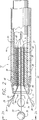
今、同じ参照番号が同じ又は対応するエレメントを指示する図面をより詳細に見ると、図1に、エネルギーを静脈のような解剖構造体に付与するためのカテーテル10が示される。カテーテル10は、作動端15に遠位オリフィスを有する外側シース12を含む。外側シース12のコネクター側端部17はハンドル16に取付けられ、ハンドル16は、電源22、典型的にはRF発生器及びマイクロプロセッサーコントローラ23とインターフェースするための電気コネクター18を含む。電源22及びマイクロプロセッサー23は、普通、1つのユニットに収容される。コントローラ23は、外部コマンド及び腔内静脈治療部位に位置する熱電対のようなセンサーからのデータに応答して電源22を制御する。他の実施形態では、使用者は、自動温度制御が存在しないように定電力出力を選択しても良いし、或いは、表示読み出しの温度を見込んで出力を手動で調整しても良い。カテーテル10は、遠位オリフィス14を通って外側シース12から出入りする拡張可能な電極装置24(部分的に図示)を含む。電極装置は複数の電極を含み、該電極は、それをシャフト内で移動させることによって、或いは、外側シャフトを電極に対して移動させることによって拡張される。図1は単一の中心電極を取り囲む複数の電極を図示するが、カテーテル用の種々の電極形態を説明する。
【0027】
内側シース28又は内側部材が外側シース12に収容される。流体ポート21が外側シース12の内部と連通する。カテーテル10はポート21を通して生理的食塩水で定期的に洗浄される。洗浄流体は外側シースと内側シースとの間を移動する。ポート21は薬物療法のうちの供給(deliver)も見込む。カテーテルを洗浄することにより、カテーテル10内の、血液のような生物学的流体の蓄積を防止する。凝固又は血栓の形成を防止すべく血液を静脈の治療領域から抜くために、静脈のような中空の解剖構造体の治療領域を生理的食塩水のような流体又は誘電流体で洗浄するのが良い。誘電流体の使用は、治療領域から消失する意図しない加熱効果を最小にする。誘電流体は、RFエネルギーの電流が静脈壁から流失しないようにする。
【0028】
1つの実施形態では、カテーテル10は管腔を含み、管腔は外側シース12の遠位先端で始まり、実質的に外側シース12の軸線に沿って走り、ハンドル16のガイドワイヤポート20で終る。カテーテル10を所望の治療部位に案内するために、ガイドワイヤがカテーテル10の管腔を通して導入される。カテーテルがより小さい静脈を治療すべく寸法決めされる場合、カテーテルの外径は、外側シース12と内側シース28との間の流体洗浄を見込む必要はない。しかしながら、この実施形態では、ガイドワイヤ用管腔を通る流体洗浄を取り入れるのが良い。
【0029】
今、図2、2a、3、4、4a及び5を参照すれば、外側シース12はシェル44及び先端部分46を含む。静脈を通して操作されるようなカテーテル10用の非外傷性の先端を設けるために、先端46は、好ましくは、遠位端が内方にテーパされ、即ち、“円錐頭”形状をなす。しかしながら、先端46は、ガイドワイヤ上で静脈管系の曲り部を通り抜けるカテーテル10の移動(tracking)を容易にする他の形状を有しても良い。円錐頭形先端46は、例えば、ショア硬度(Shore A)70のような軟らかいデュロメータ値を有するポリマーで作られるのが良い。シェル44は低い摩擦係数を有する生物学的適合性材料からなる。1つの形態では、外側シース12は静脈管腔に嵌るように寸法決めされ、例えば、1.7mm(0.07in)乃至3.0mm(1.2in)の直径に対応する5乃至9Frenchであっても良いし、或いは、適当な他の寸法でも良い。
【0030】
電極装置24は、絶縁された一次リード線30を、ある実施形態では絶縁された一次リード線30と二次リード線31とを含む多数のリード線を収容する。好ましくは、リード線は、その極性を望むように切り換えるべく電源22(図1)に接続される。変形例として、マイクロプロセッサーコントローラが極性を切り換えるのに使用され、並びに、電極装置用電力の他の特性を制御するのに使用されても良い。かくして、電極装置は双極形態でも単極形態でも作動する。隣接した一次リード線30が反対の極性を有するとき、電極装置24は双極電極装置として作動する。一次リード線30が共通に荷電されるとき、電極装置24は単極電極装置として作動する。一次リード線30が共通に荷電され且つ二次リード線31が反対の極性を有するとき、電極装置24は双極電極装置として作動する。図2及び3に示した本発明の実施形態は4本の一次リード線30及び1本の二次リード線31を有する電極装置24を示し、図4及び5に示した本発明の実施形態は4本の一次リード線30だけを有する電極装置24を示す。本発明は4本の一次リード線30に限定されず、もっと多い、或いは、もっと少ないリード線をどちらの実施形態に使用しても良い。リード線の数は、治療すべき中空の解剖構造体の寸法又は直径に依存する。並置した電極は互いに一定距離内に保たれるべきである。正確な電流密度及び正確な熱分配を確保するために、より大きい脈管はもっと多い一次リード線を必要とすることがある。
【0031】
リード線30、31の各々の絶縁体は、導線を露出させるべく遠位端32、33が取除かれる。図2、2a及び3に示すような第1の形態では、電極34は半球形状を有する。第2の形態では、電極はほぼ球の形状かスプーン形状かのいずれかを有する。図4、4a及び5に示すように、電極はスプーン形状を有し、スプーン形状は、静脈がつぶれるときにスプーン形状の輪郭を最小にするために、球又はその他の形状を形成するように組合わされる。電極34は遠位端32に一体に形成されるか、はんだ付けされるか、各一次リード線30の遠位端にそれ以外の方法で形成されるかのいずれかである。遠位端32を電極として作用するように言及するとき、これは、電極34が遠位端32に一体に形成される場合に限られないことを理解すべきである。例えば、遠位端に一体に形成された電極がある場合、電極が遠位端に別個にはんだ付けされる場合、或いは、遠位端に位置した他のエネルギー供給装置がある場合、遠位端はエネルギーを周囲組織に付与することができる。電極34は、典型的には、一次リード線30よりも大きい直径を有する。例えば、一次リード線30は0.18mm(0.007in)乃至0.28mm(0.011in)の範囲の直径を有し、電極34は0.36mm(0.014in)乃至0.51mm(0.020in)の直径を有する。一次リード線30及び電極34は、好ましくは、ステンレススチールのような生物学的適合性材料で作られる。一次リード線30を取り囲む絶縁体は、一般的には、0.03mm(0.001in)乃至0.06mm(0.0025in)の厚さを有し、その結果、組合わせたリード線−絶縁体の直径は0.23mm(0.0009in)乃至0.41mm(0.016in)になる。図2及び3に示すような変形形態では、各一次リード線30は、幅0.764mm(0.03in)乃至1.0mm(0.04in)、厚さ約0.13mm(0.005in)のストリップ形状をなし、二次リード線31は、典型的には、管形状をなす。これらの寸法を例示の目的で与え、それらを限定するつもりはないことに注目すべきである。半球形電極34は、例えば、一次リード線30の遠位端32にはんだ付けされた直径16番(1/16in,1.6mm)の球を砂で削る(sand down)ことによって遠位端に形成される。電極は、導リード線から所望の形態を打抜くことによって構成されても良い。電極はリード線と一体であり、リード線の残余は絶縁される。二次リード線31の遠位端33は、好ましくは、ほぼ球形の電極35を含む。
【0032】
整列装置36が、リード線30、31の近位端だけがカテーテルに取付けられ且つ整列装置内及び整列装置より遠位でリード線間の分離を維持するように、リード線30、31を整列させる。リード線が整列装置に取付けられるとき、リード線は片持ち体を構成する。整列装置36の好ましい形態は、整列装置の中心にない軸線方向に整列した複数の管腔38を含み、複数の管腔は整列装置36の軸線に対して実質的に対称に位置決めされる。整列装置36は、例えば、ポリアミドのような誘電材料からなる中実円柱から複数の軸線方向に整列した管腔38を押出すことによって形成される。各リード線30は個々の中心にない管腔38を通り抜けて、整列装置36の後部から出る。整列装置36は、軸線と整列した中心管腔48を更に含む。ある実施形態では、中心管腔48はガイドワイヤを受入れるために使用され、或いは、RFエネルギーの付与中、薬剤及び冷却液剤を治療領域に供給し又は灌流させるために使用される。他の実施形態では、中心管腔48を二次リード線31用に使用しても良い。整列装置36は又、温度センサーとして使用される熱電対のリード線のような追加のリード線用の補助管腔47を更に含む。整列装置36は、リード線30、31が互いに、そして存在すればガイドワイヤと連結することがあるどんな影響も防止し或いは最小にするために誘電材料からなる。1つの実施形態では、整列装置の長さは、例えば、12.5mm(0.5in)乃至19.0mm(0.75in)である。しかしながら、これらの寸法は例示の目的で与えられ、寸法を限定するつもりはない。
【0033】
図2、2a及び3に示す本発明の実施形態では、内側シース28は整列装置36に取付けられ、整列装置の後部37を越えて延びる。好ましくは、内側シース28は整列装置36の外壁を完全に取り囲み、接着剤、圧入、或いはその他の仕方で外壁に取り付けられ、その結果、整列装置36は内側シース12に対して固定位置にある。内側シース及び整列装置は、外側シースに対する内側部材として作用する。内側シース28は低い摩擦係数を有する生物学的適合性材料からなる。内側シース28は、リード線30、31と電気コネクター18(図1)との間の相互接続用経路を構成する。この相互接続は種々のどんな方法で起こっても良い。リード線30、31自体は連続であり、且つ内側シース28の長さ全体を走るのが良い。変形例(図示せず)では、正に荷電したリード線30、31は、内側シース28に収容された共通の正に荷電した導体と連結されても良い。同様に、負に荷電したリード線30、31は共通の負の導体と連結されても良い。好ましくは、リード線30、31は、切り換えられるリード線の極性を考慮に入れた導体に連結される。導体は、例えば、ポリウレタンで被覆された36番(gauge)の銅リード線からなる。連結は内側シース28内のどんな箇所で起こっても良い。カテーテル内に収容されるワイヤの量を減少させるために、リード線30、31を、それが整列装置36の後部37から出た箇所で連結させるのが有利である。電極装置24に更なる安定性を加えるために、接着材料40が整列装置36の前端でリード線30、31を取り囲むのが好ましい。この実施形態では、外側シース12が整列装置36の上を後方に引っ込められるとき、リード線30、31は遠位オリフィス14から出る。内方にテーパした先端46は外側シース12の引っ込み移動を邪魔して、整列装置36の露出を防止する。
【0034】
図3はリード線30、31を引っ込め位置で示し、この引っ込め位置では、全てのリード線が円錐頭形先端部分46及び外側シェル44の中にある。整列装置36は外側シェル44に対して移動されている。柔らかい円錐頭体は、カテーテルを蛇行静脈系を介して操作するときのための非外傷性先端部を提供する。二次リード線31の遠位端の電極を、円錐頭体46に形成された開口部とほぼ同じ寸法に寸法決めすることができる。整列装置がカテーテルの外側シースの中に引っ込められたときに、円錐頭体は二次リード線の電極と共に非外傷性先端部を形成する。このことは、円錐頭体が柔らかいジュロメーター(硬度)を有する材料で作られていない場合でも、非外傷性先端部を提供することができる。
【0035】
次いで図4及び図5を参照すると、別の実施形態では、整列装置36は、外側シース12に取り付けられ、これによって、外側シース12に対して静止したままである。内側シース28は、整列装置36の後部に移動自在に位置決めされ、一次リード線30と電気コネクタ18(図1)との間の相互接続用の経路を提供する。幾つかの実施形態では、内側シース28は内側シースの全長に亘って延びるガイドワイヤチューブ49を収容する。ガイドワイヤチューブ49は、一方の端が整列装置36の中心管腔48と、また、他方の端がガイドワイヤポート20(図1)と連通するように整列される。一次リード線30は、連続であり、内側シース28の全長に亘って延びても良いし、或いは、上述したように共通のリード線に結合されても良い。一次リード線30は内側シース28の前端27に例えばポッティング材料で固着され、内側シース28が移動すると、これに対応して一次リード線30を整列装置36の管腔38の中を移動させる。この実施形態では、一次リード線30は、整列装置36に固着されておらず、本質的に軸線方向における自由浮動リード線である。内側シース28の前端が整列装置36の後部37に向って移動されると、一次リード線30は、整列装置36の中を移動し、遠位オリフィス14から出る。
【0036】
上記実施形態では、一次リード線30は、互いに遠ざかり、これにより、接触を回避するように、形成され、例えば、弧状にされ又は曲げられる。一次リード線30の「遠位部分」は、かかる一次リード線が遠位オリフィス14から完全に延ばされたときに、整列装置36の前端から延びるリード線の部分である。これらの遠位部分42は、整列装置36の軸線に対して互いに半径方向外方に移動して対称配列を形成するように形成されるのが好ましい。このことは、図2a及び図4aの両実施形態に示されている。一次リード線30の弧又は曲げ度合は、かかる一次リード線が遠位オリフィス14から外側シース12を出たときに、リード線を半径方向に拡張するのに十分である任意のものである。弧又は曲げ度合は、一次リード線30が血液の中で拡張し、電極34が静脈壁と並置するのに十分な力を与えるのに十分であることが重要である。電極34は、完全接触を保証するため、静脈壁に部分的に埋設されるのが好ましい。電極の丸い部分は静脈壁に埋設されて完全面並置を達成し、電極の非絶縁面領域全体は、効果的電流分布のため、静脈組織と接触している。静脈組織と接触している電極の面積は、静脈組織のスポット加熱をもたらす高い電流密度を回避するのに十分であるのが好ましい。加熱効果は、静脈の周囲バンドに沿って分布されるのが好ましい。並置された電極は、静脈の円周に沿って互いに4mm又は5mm未満、間隔を隔てられなければならない。かくして、電極構造体は、治療すべき静脈の寸法又は直径に関連している。リード線形状や絶縁厚さのような一次リード線30の他の特性はリード線の押力に影響を及ぼし、弧又は曲がり度合いは、これらのファクターを補償するように、調節されなければならない。例えば、電極装置24の一つの形態では、0.18mm(0.007インチ)乃至0.28mm(0.011インチ)の直径を有し、0.05mm(0.002インチ)乃至0.13mm(0.005インチ)の全体の絶縁厚さを持ったワイヤは、解剖構造体に対して十分な並置状態をなすように、鋭角に弧状にされ、または、曲げられる。これらの寸法形状が例示目的で提供されたのであって、限定のために提供されたものではないことを理解すべきである。
【0037】
リード線がカテーテルの作動端で延ばされたらすぐにかかるリード線を外方に拡張するための他の技術も可能であるかも知れない。例えば、リード線は、真っ直ぐであるが、これらのリード線が常時外方に差し向けられるような角度で整列装置に取り付けられても良い。
【0038】
並置力を増大させるため、一次リード線30を、例えば幅0.76mm(0.03インチ)乃至1.0mm(0.039インチ)及び厚さ約0.13mm(0.005インチ)の寸法を有する、断面が矩形である、ストリップ形状にするのが好ましい。矩形断面は、幅寸法では曲げ抵抗を増大させるが、厚さ寸法ではより自由な曲げを可能にする。この一次リード線30のストリップ形状の形態は、図2、図2a及び図3に示され、半径方向における必要な曲げを可能にしながら横方向における安定性を増大させる。図2、図2a及び図3では、各一次リード線は矩形断面を有し、矩形断面は、この矩形断面の薄い方の寸法部分がリード線の拡張方向と整合するようにカテーテルに関して取り付けられる。リード線は、外方に拡張されたときに、横方向にほとんど曲がることはなく、リード線間の間隔はより均一に保証される。均一な間隔は、リード線の遠位端で電極と並置している静脈組織の周囲に均一な加熱を作り出す。
【0039】
リード線30の遠位部分の長さはまた、電極装置24の形態に影響を及ぼす。互いに対向した2つの電極34間の最大距離、すなわち、電極装置24の有効直径は、遠位部分42の曲げ度合い及び長さによって影響される。遠位部分42の長さが長ければ長いほど、電極装置24の直径は大きくなる。従って、遠位部分42の長さ及び弧又は曲げ度合いを変更することによって、カテーテル10を異なる大きさの解剖学的構造体に使用することができるように形作ることができる。
【0040】
異なる数のリード線30、31をカテーテルに採用することができる。リード線30、31の数は、整列装置36の直径及び整列装置の中に押出される管腔36、38、47の数によって制限される。双極形態では、偶数の一次リード線30を利用して、多数の正負に荷電された電極対を形成するのが好ましい。解剖学的構造体に対して並置している電極は互いに対して或る距離内に保持されるべきである。単極形態では、任意の数の共通電荷リード線30が存在しても良い。単極モードでは、解剖学的組織へのRFエネルギの分配は、組織から離れた箇所に大きな金属パッドのような戻し装置を設けることによって、組織を通る電流の戻り経路を作ることによって得られる。
【0041】
次いで、再び、図1を参照すると、アクチュエータ25が、遠位オリフィス14からの電極装置24の延びを制御する。アクチュエータ25は、スイッチ、レバー、ネジ付制御ノブ、或いは、、その他の適当な機構の形態を取ることができ、場合により、外側シース12又は内側シース28の移動に亘って微調整を行うことができるものであるのが好ましい。本発明の一つの実施形態では、アクチュエータ25(図1)は、外側シース12(図2、図2a及び図3)とインターフェースし、内側シース28に対して外側シース12を前後に移動させる。別の実施形態では、アクチュエータ25(図1)は、内側シース28(図4、図4a及び図5)と協力して、外側シース12に対して内側シース28を前後に移動させる。かくして、外側シースと内側シースとの間の相対的位置が制御されるが、その他の制御策を使用することもできる。
【0042】
再び、図2、図2a図3、図4、図4a及び図5を参照すると、カテーテル10は、熱電対のような温度センサを有する。温度センサ26は、該センサ26が電極34の露出面と実質的に面一であるように、電極34の適所に取り付けられている。センサ26は、図解の明瞭化のためにのみ、電極から突出するように図示されている。センサ26は、露出した電極面と並置状態にある解剖学的組織の一部の温度を検知する。解剖学的組織の温度を検知することによって、いつ組織の収縮が始まろうとしているかを良好に指示することができる。解剖学的組織に面する電極に置かれた温度センサ26が、いつ収縮が起こる(70℃、或いは、それ以上の温度)か、及び、いつ著しい量の熱誘導凝血が電極に生成し始めるかの指示を行う。従って、温度を70℃以上に維持することは解剖学的構造体の治療収縮をもたらす。監視されている温度がオペレータによって選択された特定温度、典型的には、解剖学的組織が焼灼し始める温度に達したとき、或いは、これを越えたときには、電極34からのRFエネルギの付与は中止され、または、減じられる。温度センサ26は、一対のセンサリード線45を介して制御装置23(図1)とインターフェースし、一対のセンサリード線45は、補助管腔47、次いで、内側シース28の中を延びるのが好ましい。温度センサ26からの信号は制御装置23に与えられ、この制御装置23が電極34に供給されるRFエネルギの大きさを選択された温度基準及び監視温度に従って制御する。静脈の過熱を回避するために静脈の収縮が検出されたときに電極から静脈部へのRFエネルギの付与を止め、または、調節する自動装置に、インピーダンス監視や超音波パルスエコーのようなその他の技術を利用することができる。凝血生成の始まりを検出するのにインピーダンスを用いることができる。
【0043】
図6,6a及び図7a乃至図7cを参照すれば、カテーテル10の1つの実施態様の操作の際、カテーテルを静脈52のような中空の解剖構造体の中に挿入する。カテーテルは、図2及び3と関連して述べた実施態様と同様である。カテーテル10はさらに、外部シース60を有し、その中を通って流体が治療部位に送出される。この実施の形態では、流体ポート(図示せず)は、外部シース60の内部と流通し、流体は、外部シース60と外側シース12との間から送出される。外部シース60は、外側シース12を取り囲んで、流体が流れる同軸のチャネルを形成する。
【0044】
蛍光透視法、超音波及び血管造影画像技術、或いは他の技術を用いて、カテーテルの特定位置を差し向けて、さらに静脈内における位置を確認するのがよい。次いで、アクチュエータ(図示せず)を作動して、外側シース12を後方に引っ込めたり、或いは内側シース28を前方に進めることによって、外側シースを内側シースに対して移動させて、遠位オリフィス14を通してリード線30,31を露出させる。リード線30,31が遠位オリフィス14を出るにつれて、一次リード線30は、整列装置36の軸線に対して半径方向外方に膨張し、一方二次リード線31は、略直線のままである。一次リード線30は、外方に移動し続けて、静脈壁54との近接が起こり、さらに一次リード線30の外方への移動が妨害される。一次リード線30は、静脈壁54の略円周方向のバンドに沿って静脈に接触する。一次リード線30のこの外方移動は、略対称の仕方で起こる。その結果、一次リード線電極34は、静脈壁54の円周方向バンドに沿って略等間隔に間隔を隔てる。中心リード線電極35は、静脈壁54に接触することなく、静脈52内に懸架される。
電極34が静脈の治療部位に位置決めされたとき、電源22を付勢して、適当なRFエネルギーを作る。1つの適切な周波数は、510kHzである。付与されるエネルギーの周波数を選択するのに用いられる1つの基準は、静脈組織内での熱効果の、深さを含む広がりにわたって所望される制御である。別の基準は、熱電対からのRFノイズを除去するためのフィルター回路との適合性である。
【0045】
双極操作では、最初、隣接したリード線が反対に荷電され、二次リード線が電気的に中性であるように一次リード線30を荷電する。これらの多くの対の反対に荷電したリード線30は、活性電極対を形成して、それらの間にRFフィールドを発生する。かくして、別個のRFフィールドが、静脈壁54の円周方向バンドに沿って設定される。これらの別個のフィールドは、反対の極の隣接した電極34が互いの間にRFフィールドを発生するので、静脈壁54の円周方向バンド全体に沿って、対称なRFフィールドパターンを形成する。一様な温度分布が、治療される静脈壁に沿って達成される。RFエネルギーは、隣接した静脈組織内で熱に変換され、この熱効果によって静脈組織が収縮し、静脈の径を減じる。治療される静脈壁に沿う一様な温度分布は、治療領域内のホットスポットの形成を避け、それと同時に静脈の径の制御された一様な減少を促進する。熱効果は,静脈内のコラーゲン繊維の構造的な変態を生じる。コラーゲン繊維は、短くなり、さらに熱効果からの熱に応じて断面が厚くなる。図7aに示すように、エネルギーによって、静脈壁54は一次リード線電極34の周りにつぶれる。壁54はつぶれ続け、更なるつぶれは電極34によって妨害される。電極は更に、収縮している静脈壁54によって互いにさらに押圧され、電極は接触し、その時点で壁54のさらなるつぶれ或いは結紮が妨害される。静脈壁54の一次リード線電極34の周りのつぶれの際、一次リード線電極の極性は、切り換えられ、あらゆる一次リード線電極は、共通に荷電される。リード線のための極性の切り換えは、同時である必要はない。RFエネルギーの付与を中止し、極性を切り換えることができ、そしてRFエネルギーを再び切り換えられた極性で付与する。次いで、二次リード線電極35を、その極性が一次リード線電極34の極性と反対であるように荷電する。RFフィールドは、一次リード線電極34と二次リード線電極35との間に設定される。
次いで、カテーテルを引き戻し、一方エネルギーを電極装置に付与する。図7bに示すように、カテーテル10を引き戻す間、一次リード線電極34は、静脈壁54と近接したままであり、一方二次リード線電極35は、一次リード線電極34によってすでにつぶされた静脈壁の部分と接触するようになる。したがって、RFエネルギーは、静脈壁54を通って一次リード線電極34と二次リード線電極35との間を通り、カテーテル10が収縮されるにつれて、静脈壁は二次リード線電極35の周りにつぶれ続ける。図7cに示すように、この方法による結紮は、静脈52の長さに沿う閉鎖を生じる。長い閉鎖は、鋭い閉鎖と反対に、強くしかも再疎通を受けにくい。一次および二次リード線を有するカテーテル10を単極の仕方で作動するときに、同様な結果が達成される。単極の操作では、二次リード線電極35は中性のままであり、一方一次リード線電極30は共通に荷電され、人体と外部接触して配置された大きな低インピーダンスリターンパッド(図示せず)のように従属電気装置と関連して作用して、一連の別個のRFフィールドを形成する。これらのRFフィールドは、静脈の円周方向の周りにほぼ均等に間隔を隔て、静脈壁の軸方向長さに沿って走り、静脈壁を一次リード線電極の周りにつぶす。静脈壁のつぶれの際、二次リード線電極を一次リード線電極のそれと同極を有するように荷電する。電極装置を引くと、双極操作で述べたように、静脈壁はつぶれる。
双極あるいは単極の操作のいずれにおいても、RFエネルギーの付加は、静脈52の径にかかわらず静脈壁を通してほぼ対称に分布する。RFエネルギーのこの対称分布は、予測性、収縮の均一性及び閉鎖の強度を増大させる。更に、エネルギーの均一な分布は、短い時間の間RFエネルギーの付与を可能にし、それによって電極34上の熱誘導凝塊の形成を減じるか回避する。電極の非凸型外部を有するリード線は、絶縁されて取り囲む血液の加熱をさらに防止する。
【0046】
外部シース60と外側シース12との間に形成された同軸のチャネルを通して流体を治療される静脈のRF加熱の前およびその間に、送出してもよい。別の管腔をカテーテルに形成して、流体を治療部位に送出することができることを理解すべきである。送出された流体は、血液の加熱および凝固を回避するように静脈からの血液を移動或いは放血させる。流体をRF治療の間送出し続けて、血液が治療部位に循環して戻るのを防止してもよい。誘電性流体の送出は、RFエネルギーが静脈壁の組織の中に向けられるように、取り囲むインピーダンスを増大させる。
【0047】
図8、8a、9aおよび9bを参照すれば、カテーテル10の変形例の操作では、カテーテルをガイドワイヤー53と共に用いてもよい。前の実施例におけるのと同様に、カテーテル10を静脈52のような中空の解剖構造体に挿入する。ガイドワイヤー53をエネルギーの付与が望まれる位置を越えて進める。次いで、カテーテル10を中心管腔48及びガイドワイヤーチューブ49(図4)を経由してガイドワイヤー53に挿入し、更に静脈を通して所望位置までガイドワイヤー上を進める。典型的には、ガイドワイヤー53を、RFエネルギーが電極装置24に付与される前に引き戻し、或いは取り除く。
【0048】
次いで、アクチュエータ25(図1)を操作して、外側シース12を後方に引くか、或いは内側シース28を前方に進めるかして、リード線35を遠位オリフィス14を通して露出させる。リード線30は、遠位オリフィス14を出て、整列装置36の軸線に半径方向外方に膨張する。リード線30は外方に移動し続け、静脈壁54との近接が起こる。リード線30は、静脈壁54のほぼ円周方向バンドにそって静脈に接触する。リード線のこの外方向移動は、ほぼ対称な仕方でおこる。その結果、電極34は静脈壁54の円周方向バンドに沿ってほぼ均等に間隔を隔てる。変形例として、電極が同じ面に沿って位置しないように、互い違いの仕方で間隔を隔ててもよい。たとえば、電極が互いの方につぶされるとき、より小さな断面輪郭を達成するように隣接した電極がカテーテルから異なる長さ延びるようにすることができる。
電極34が静脈の治療部位に位置決めされたとき、電源22を付勢して適当なRFエネルギーを電極34に与え、カテーテル10をすでに述べたように双極或いは単極いずれかの仕方で作動する。図9a及び9bに示すように。エネルギーは静脈壁54を電極34のまわりでつぶして、リード線をほぼ真っ直ぐにし、さらに電極を互いのまわりに集める。壁54はつぶれ続け、さらなるつぶれは電極34(図9b)によって妨害される。この時点で、エネルギーの付与が終るのがよい。互いにつぶされるとき、減じた輪郭を備えた形状を形成するように、電極を構成してもよい。電極はまた、静脈壁のつぶれによって減じた輪郭の形状を形成した後、RFエネルギーを付与し続けるように構成され且つ絶縁されてもよい。カテーテル10を引き戻して、隣接した静脈セグメントを結紮してもよい。温度センサー26が含まれる場合、静脈組織の温度がコントローラ23によって構成されるような許容レベルより上昇するなら、完全なつぶれの前にエネルギーの付与を止めてもよい。
【0049】
カテーテルが流体送出管腔(図示せず)を含むところでは、流体を治療される静脈のRF加熱の前およびその間に送出してもよい。流体を静脈内の治療部位から血液を移動させて、血液の凝集を避けることもできる。流体は誘電性の媒体でもよい。流体は、治療部位における血液の凝固を化学的に起こさないようにすることができるヘパリンのような抗凝血剤を含んでもよい。
【0050】
選択された静脈部分に対する治療を完了した後、アクチュエータ機構により、一次リード線を外側シース12の内部に戻す。外側シース又は内側シースのいずれかを動かして、2つのエレメントの位置を互いに相対的に変える。リード線30が外側シース12の中に入ったら、結紮工程を繰り返さす他の静脈部分に、カテーテル10を移動させることができる。全ての静脈部位を治療したら、カテーテル10を血管系から取り出す。次いで、静脈へのアクセス箇所を縫合し、閉じ、又は、出血が制御されるまで局所的な圧力を加える。
【0051】
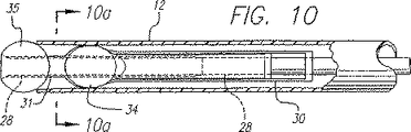
カテーテルのもう一つの実施態様を図10に示す。インナ部材即ち内側シース28が、外側シース12内に収容されている。内側シースは、ポリイミド、ポリエチレン、又は、ナイロンのような可撓性ポリマーから構成されているのが好ましく、カテーテルの全長にわたって移動できる。カテーテルの大部分は、静脈系の蛇行経路を進むことができるように、可撓性であるべきである。フレア付遠位端33と環状断面形状を有するハイポチューブが、内側シース28の遠位端を覆って取付けられている。ハイポチューブは、長さがわずか約2ないし3mmであるのが好ましい。ハイポチューブは、導電性二次リード線31の一部分として機能する。絶縁されていない導電性電極球体35が、ハイポチューブに滑り込まされる。ハイポチューブのフレア付遠位端が、電極球体がハイポチューブの遠位端を越えて移動するのを防止する。この球体は、例えば、球体の前後をハイポチューブに半田付けすることによって、ハイポチューブに恒久的に取付けられている。球形電極35の大部分または全ての表面は、絶縁されていないままである。ハイポチューブの残部は、球体形状の遠位端が電極として作用することができるように、絶縁されるのが好ましい。例えば、ハイポチューブを、パリレンのコーティングのような絶縁材料で覆ってもよい。ハイポチューブの内側管腔は、ハイポチューブのフレア付遠位端にエポキシのような接着剤で取付けられた内側シース28で内張りされている。
【0052】
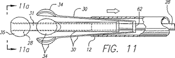
好ましくは、平らな矩形ストリップ形状を有し且つアームとして作用することができる、複数の一次リード線30が、二次リード線31および球体電極35を囲んでいる。図11に示されているよう、複数の一次リード線が、共通の導電性リング62に接続されているのが好ましい。この形態は、内部の電気接続の数を減らしながら、複数の一次リード線の位置を維持する。リング62は、内側シース28に取付けられている。外側シースに対するリングおよび一次リード線の位置は、内側シースの位置に追従する。上述したように、二次リード線31のハイポチューブも、内側シース28に取付けられている。異なった一次リード線の極性を別々に制御できるように、2つの別々の導電性リングを使用するのがよい。例えば、隣接したリード線が反対の極性か同じ極性のいずれかを有するように切り替えられるように、隣接した一次リード線を2つの別々の導電性リングの一方に接続してもよい。このリングは、近い間隔をおいているが、内側シースに沿って電気的に隔絶されていることが好ましい。リングとハイポチューブとの両者が、内側シースと結合されており、リングに接続された一次リード線30は、互いに電気的に絶縁されたまま二次リード線と一緒に移動する。エポキシまたは他の適当な接着剤を使用して、リングを内側シースに取付けるのがよい。それぞれのリングからの一次リード線は、内側シースの円周に沿って互いに交互になる。リード線の下側に沿う絶縁がリング間の電気的短絡を防止する。
【0053】
リングと一次リード線は、リングが基部を形成し且つ矩形の一次リード線が片持ちばりアームとして作動する片持ちばりとして作用するように、一緒に取り付けられる。リード線30は、リングに連結され、且つ、リード線がカテーテルからこれを囲んでいる静脈組織に向かって外方に撥ね返る傾向があるアームとして作用するように、弧又は曲がりを有するように形成されている。リード線の下側とリングに沿う絶縁が、リングと向い合ったリングとの間の意図しない電気的接続を防止する。変形例では、リード線は真っ直ぐに成形され、リード線がリングから半径方向外方に拡張し又は撥ね返る傾向があるように、リングにある角度に連結される。リード線をリングに取付ける角度は、一次遠位端と電極34とを、血液の中を押し通して静脈壁と並置させるのに十分であるべきである。リード線の形状、絶縁体の厚さのような一次リード線30の他の特性は、リード線の押し力に影響を及ぼし、且つ、弧または曲げ度合は、これらの要因を補償するように調整されるべきである。リード線30の矩形断面は、半径方向に必要な曲げを許容しつつ、横方向における安定性を大きくすることができる。リード線30は、外方に拡張したとき、横方向に曲がりにくく、リード線間の均一な間隔がより確保される。リード線30と遠位端との間の均一な間隔は、電極34による静脈の回りの均一な加熱を促進する。
【0054】
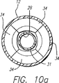
一次リード線30の遠位端は、絶縁されておらず、スプーン形状すなわち半球形状を有する電極34として作用する。リード線は、リード線の遠位端で一体の形状電極を形成するように、打ち抜かれるのがよい。解剖構造体の壁に対して適所に配置されることになる遠位端電極34の非絶縁外側部分は、丸い且つ凸形であるのが好ましい。遠位端の平らな又は非凸形の内側部分は、静脈内の周囲の血液に対する、意図しない熱的作用を最小にするように、絶縁されている。遠位端電極34は、図10aに示されるように、遠位端が内側シース12に向かって押されるとき、遠位端が組み合わさって、二次遠位端の球形電極の輪郭より小さな輪郭を備えたほぼ球形形状を形成するように、形作られている。
【0055】
外側シース12は、一次および二次リード線30、31を囲んで上を摺動できる。外側シース12は、電極として機能する二次遠位端の球形電極35とほぼ同じ寸法を有するように寸法決めされたオリフィスを含んでいる。二次遠位端の電極35と、外側シース12のオリフィスとの間で、締まり嵌め又は滑り嵌めが達成される。この形態は、カテーテルに非外傷性先端を与える。二次遠位端の電極35は、オリフィスより僅かに大きいことが好ましい。外側シース12の内径は組み合わされた一次遠位端電極34の小さくなった輪郭とほぼ同じである。組み合わされた一次遠位端電極34の小さくなった輪郭の直径は、外側シースの内径より小さいことが好ましい。
【0056】
流体が外側シース12と内側シース28との間を流れることができるように、流体ポート(図示せず)が外側シース12の内部と連通するのがよい。変形例として、流体ポートが、ガイドワイヤを受け入れることができるハイポチューブの中心管腔48と連通してもよい。上述したように、カテーテル10内での血液のような生体流体の停滞を防止するため、カテーテル10は生理食塩水で周期的に洗浄される。カテーテルを、所望の治療部位に、案内する際に使用するために、ガイドワイヤを、管腔48の中に導入するのがよい。上述したように、管腔を通して、流体を、同様に、流し又は配送させるのがよい。中心管腔を望まなければ、ハイポチューブの管腔をはんだで満たしてもよい。
【0057】
一次リード線30と接続リングは、リード線の極性が所望に応じて切り替えられるように、電源に接続されているのが好ましい。これにより、電極装置24が、二極形態か単極形態のいずれでも作動することが可能となる。隣接した一次リード線30が反対の極性を有するときには、二極電極作動が可能となる。一次リード線30が共通に荷電されるときには、患者に接触して配置された大きな帰路電極との組み合わせで、単極電極作動が可能となる。一次リード線30が同じ極性に荷電され、二次電極31が反対の極性を有するときには、二極電極作動が可能となる。もっと多く或いはもっと少ない電極を使用してもよい。リード線の数は、治療する中空解剖構造体の寸法即ち直径に依存するのがよい。
【0058】
図示はしないが、カテーテル10が、遠位端すなわち電極34の適所に、電極34の露出表面とほぼ面一になるように取付けられた熱電対のような温度センサを含むのがよいことがわかる。このセンサは、電極の露出表面と整列した解剖構造体部分の温度を検出する。監視温度が、解剖構造体組織が焼灼し始める温度のような、オペレータによって選択された所定温度に達する又はこれを越えると、電極34からのRF(無線周波数)エネルギ付与を停止あるいは減少させる。インピーダンスモニタ、超音波パルスエコーのような他の技術を、静脈の過熱を防止するために、静脈の十分な収縮を検出したとき電極から静脈部分へのRFエネルギの付与を停止又は調整する自動化システムに利用してもよい。
【0059】
今、図12乃至14を参照すれば、カテーテル10の1つの実施形態の操作では、カテーテルを静脈のような中空の解剖構造体に挿入する。蛍光透視法、超音波法、血管鏡結像技術、又は他の技術を、静脈中のカテーテルを特定の位置に差し向け、確認するために使用することができる。次いで、アクチュエータを操作して外側シース12を引っ込め、リード線30、31を露出させる。外側シースはもはやリード線を拘束しないので、一次リード線30は外側シースによって定められる軸線に対して外方に移動し、二次リード線31は外側シースによって定められる軸線に沿って実質的に直線のままである。一次リード線30は、その遠位端電極34が静脈壁54と並置して置かれ、一次リード線30の外方への移動が妨げられるまで外方に移動し続ける。一次リード線30は静脈壁54のほぼ円周領域に沿って静脈と接触する。一次リード線30のこの外方への移動は、一次遠位端電極34が実質的に等間隔をなすように、実質的に対称的に起る。中心リード線電極35は静脈壁54に接触せずに静脈の中に宙吊りにされる。
【0060】
電極34が静脈の処置部位に位置決めされたとき、電力供給部22を作動して、適当なRFエネルギーを付与する。双極操作では、一次リード線30は、初めに、隣接したリード線が反対に荷電されるように荷電されるが、二次リード線は電気的に中性である。これら反対に荷電したリード線30の複数の対は、アクティブ電極対を形成して電極の間にRF電界を発生し、静脈壁の円周バンドに沿って対称的なRF電界パターンを形成して、処置される静脈壁に沿って均一な温度分布を達成する。
【0061】
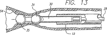
RFエネルギーは、静脈組織を収縮させて、静脈の直径を減じる熱的効果を発生する。図13に示すように、エネルギーにより静脈壁をつぶれさせ、ついには電極34によって更なるつぶれが妨げられる。電極は収縮する静脈壁によって互いにより近く圧縮される。電極34は互いに圧縮されて、静脈が効果的に結紮されるように、十分に小さい減小輪郭形態を呈する。一次リード線電極34の周囲の静脈壁がつぶれる際、一次リード線電極の極性を、一次リード線電極の全てが共通に荷電されるように切り換える。次に、二次リード線電極35を、二次リード線電極35の極性が一次リード線電極の極性と反対になるように荷電する。一次電極34と二次電極35とが互いに十分に近い間隔をなしており、静脈壁が一次リード線電極の周りでつぶれたとき、二次リード線の遠位端の電極は又、静脈壁の一部分と接触することができ、その結果、RF電界が一次電極34と二次電極35との間につくられる。
【0062】
リード線の遠位端の電極と静脈壁との間の並置を確実にするためにカテーテル10を引き戻す。カテーテル10が引き戻されているとき、一次リード線電極34は静脈壁54と並置されたままであり、二次リード線電極35は、一次リード線電極34によって予めつぶされた静脈壁の部分と接触する。RFエネルギーが一次リード線電極34と二次リード線電極35との間の静脈組織の中を通す。カテーテルが引っ込められているときの結紮は、鋭い点閉鎖よりも強く、再疎通しにくい長い閉鎖を生じさせる。
【0063】
単極操作では、二次リード線電極35は中性のままであるが、一次リード線30は共通に荷電され、身体と外部的に接触して配置される大きな低インピーダンス戻りパッド(図示せず)のような独立した電気的デバイスと共に作用し、静脈の円周の周りに間隔を隔てて実質的に均一にRF電界を形成する。それらのRF電界によって静脈壁の軸線方向長さに沿って発生した熱的効果は一次リード線電極の周りの静脈壁をつぶす。静脈壁をつぶす際に、二次リード線電極を、一次リード線電極の極性と同じ極性を持つように荷電する。電極デバイスを双極操作において説明したように引っ込める。
【0064】
双極操作又は単極操作いずれにおいても、RFエネルギーの付与は静脈壁に亘って実質的に対称的に分布される。前記のように、電極は静脈の円周に沿ってわずか4又は5mmの間隔を隔てられるべきであり、それが設計した電極カテーテルの目標静脈直径を定める。電極が実質的に対称的な配列で実質的に等間隔に隔てられ、電極間の間隔が維持された場合、RFエネルギーの対称的な分布が、収縮及び閉鎖の強さの予測性及び均一性を増す。
【0065】
図14に示すように、電極34を静脈壁と並置した後(図12)、エネルギーを付与して静脈を結紮する(図13)前に、弾性圧縮ラップ、又は超音波を通す窓を有する膨張可能ブラダー(bladder)のような外部止血帯を、脚のような解剖構造体を圧縮するために使用して、構造体を取り囲んで静脈の直径を減じる。止血帯によって付与される圧縮力は、静脈を平らにすることによって効果的に静脈を結紮し、さもなければ静脈を閉鎖するが、或る静脈に対しては、この圧縮力は静脈を完全に閉鎖しない。この場合、固定直径電極カテーテルは効果的ではない。形成したリード線30によって外方に拡張する電極34がこの状況に適合する。
【0066】
静脈の直径の減少は、静脈の予備形成を助け、結紮状態に成形されるように静脈を準備する。外部止血帯の使用は又、静脈を放血させ、血液を処置部位から押しのける。処置中の血液の凝固をこの処置によって回避する。エネルギーが、電極から、放血させた静脈に付与され、静脈は十分に減少した直径に形成され、結紮を達成する。外部止血帯は回復を助けるために適所に残しておいても良い。
【0067】
静脈の長い区間を結紮するためにRFエネルギーの付与中、カテーテルを引き戻しても良い。そうすれば、静脈の直径を減少させた単一個所の代りに、静脈の長い区間がカテーテルからのRFエネルギーによって塗られる。この仕方でカテーテルを引っ込めることにより、再疎通しにくい長い閉鎖を生じさせる。一次及び二次電極の組合せ使用は、静脈の長い長さに亘って効果的に直径を減少させる。止血帯が静脈を圧縮している間に、カテーテルを移動させることができ、その後、止血帯を取り除く。
【0068】
カテーテルが流体配送管腔を含む場合、RFエネルギーが静脈に付与される前に流体を静脈に配送することができる。止血帯が静脈を圧縮した後でさえ、血液が処置部位に存在しないことを確実にするために、配送された流体が処置部位から血液を移動させる。
【0069】
止血帯が、超音波を通す窓を有する膨張可能なブラダーである場合、膨張するブラダーによって付与される圧縮力による静脈の偏平、又は静脈の直径の減少を監視するために、超音波変換器が使用される。窓はポリウレタン又はポリウレタンの袋の間に収容されたスタンドオフ(stand-off)のゲルから形成することができる。ゲルは、変換器による静脈の超音波結像を容易にするために窓に付与することができる。窓を通る超音波視覚化により、オペレーターは、所望の静脈処置領域をさがすことができ、静脈がいつ効果的に結紮され又は閉鎖されたかを決定することができる。超音波視覚化は、電極からのRFエネルギーによって生じさせる熱的効果によって結紮状態に成形する準備に、静脈の任意の予備形成を監視するのを助ける。
【0070】
選択した静脈部分に対する処置を完了した後、アクチュエータによりリード線30を外側シース12の内部に戻す。一旦、リード線30がシース12の中に入れば、結紮処置を繰り返す別の静脈部分にカテーテル10を移動させることができる。
【0071】
別の実施形態では、図15に示すように、カテーテルにバルーン64を配置し、静脈を閉鎖するために、バルーン64をポート66によって膨張させることができる。膨張したバルーンは血流を妨げ、エネルギーを静脈壁に差し向けることによって凝固の発生を減じるために、高インピーダンス流体の静脈への注入を容易にする。エネルギーの付与前に静脈を閉鎖するバルーンの膨張は、静脈を閉鎖する止血帯の使用を不要にする。その上、又、これにより、圧縮止血帯が静脈を圧縮して閉鎖することができないような深い静脈についてでも、静脈を閉鎖させる。静脈を閉鎖する透過性でない障壁をつくるべくカテーテルの直径を拡張させるのに他の機構を使用しても良いことを理解すべきである。
【0072】
バルーン64の膨張後そして外部シース60と外側シース12との間に形成された同軸チャンネル62を通じて静脈のRF加熱を行う前に、流体61を送り込むことができる。勿論、処置の個所に流体を送り込むのに、カテーテルの中に他の管腔を形成してもよい。例えば、流体の送り込みのために、ガイドワイヤを通す管腔を用いてもよい。送り込まれた流体によって、残っている血液が静脈の処置領域から移動または放血され、血液の加熱および凝固を防止することができる。血液が処置個所に戻るのを防止するために、RF処置中、流体を送り続けてもよい。高誘電性流体を送り込むことで、周囲のインピーダンスを高め、RFエネルギが静脈壁の組織に差し向けられる。エネルギを、血液の中に分散させるのではなくターゲットつまり静脈壁に差し向けるので、より少ないエネルギが用いられる。したがって、静脈壁はエネルギを血液に到達させる場合におけるよりも、急速に所望の温度に達することができ、これは冷却効果を有する。更に、この対処によって血液凝固が回避される。なぜならば、血液を追いやって血液の凝固を防止する、ヘパリンと混合した脱イオン水のような他の流体で血液が置換されるからである。
【0073】
この実施例の部分断面が図16に示されている。同軸の膨張管腔72を提供するために、膨張シース70が外部シース60を取り囲んでいる。膨張管腔72はポート66と流体が連通できる状態にある。バルーンを膨張させるのに生理食塩水や他の適当な流体を用いることができる。
【0074】
図17に示すように、実施例では、バルーン64を、電極を有する弓のように曲る部材つまりアーム76と組み合わせて用いることができる。ここに、カテーテルのバルーン64と弓のように曲るアーム76との間に潅流孔78が形成されている。この実施例でのバルーン64は、バルーン膨張管腔72を通じて膨張させられる。静脈を処理するための撓み可能なアームの使用は、米国特許出願第08/610,911で説明されているので、これをこの明細書に援用する。アーム76を、カテーテルから半径方向外方に跳ね返るように構成してもよく、これにより、血管の直径が閉鎖まで小さくなったときに、カテーテルに向って戻る際の抵抗を小さくすることができる。カテーテルの潅流孔78を通じて抗凝血剤や生理食塩水又は高インピーダンス流体を導入又は流してもよい。先に説明したように、高インピーダンス流体は、静脈処置領域から血液を押しのけ、エネルギが血液のような導電性媒体の中に拡散するのを防止することができる。
【0075】
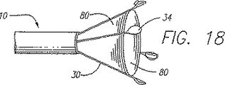
図18に示すように、他の実施例では、静脈内での血液の流れを防止するために、電極34のリード線30の周り又は内側に可撓性覆い80が嵌まり込む。ウェブ形覆いが静脈内の血液の流れを阻止するために、リード線が開口部の外に延ばされたときに、覆い80は、カテーテルの円周に沿って外側へ広がったリード線の間の領域に及ぶ。覆いは、電極から離れた一方の側に血管を保持するウェビング又は傘と考えてもよい。電極が静脈壁と並置すると、電極34と覆い80との間の隙間(仮にあるのであれば)を除くか、さもなくば最小にすべきである。覆い80は、流体に対して不浸透であるべきである。適当な材料としては、PET、ナイロンがある。リード線が引き込まれるときにリード線が緊密に一緒に移動する必要があるときには、エラストマー材料も叉適当であり、エネルギの付与によって静脈の直径が減じられるときのリード線の移動との干渉を最小にすることができるので好ましい。この実施例を一次リード線だけで図示してあるが、勿論、この実施例はこれに限定されるものではなく、覆いの使用に影響を及ぼすことなく、カテーテルと共に二次リード線を含んでいてもよい。先に開示したバルーンについてのように、エネルギの付与の前に覆いが静脈を閉鎖し、血液の流れを止めるのに外部の圧縮止血帯の必要性が求められない。更に、このことによって、圧縮止血帯では静脈を圧縮して閉鎖させることができない深い静脈に関してでもこれを閉鎖させることができる。脱イオン水のような高いインピーダンス流体やヘパリン、生理食塩水、その両者或いは脱イオン水とヘパリンのような抗凝血剤を、エネルギの付与の前に潅流孔78を通じて注入つまり流し込んでもよい。電極は、潅流孔78を通じて流される流体用の導管として機能するシャフト管腔を貫通して延びている。RFエネルギの付与による結紮効果を高めるために、硬化流体を静脈処置の個所に送り込んでもよい。先に説明した流体に加えて又はこれに置換して硬化流体を加えてもよい。
【0076】
図19に示す実施例にあっては、血液が覆い80の凹部分によって捕獲されるようになり且つ血液の体積が覆いの展開を維持するように、パラシュート形状の覆い80を差し向けてもよい。この例では、覆い80は、血液をバルーンの中に集めさせてバルーンを拡張させる開口84を備えたバルーンである。この覆い80をカテーテルシャフトに恒久的に取り付けることができる。カテーテルを、膨張状態のバルーンと一緒であっても静脈に沿って移動させることができる。
【0077】
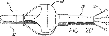
図20に示す実施例にあっては、覆い80は、カテーテルシャフトを囲む外側カニューレ82に連結され且つ作動機構つまりレバーに連結されている。この外側カニューレ82をカテーテルの長手方向軸線に沿って摺動させて、パラシュート覆い80の一端をカテーテルシャフトに沿って軸線方向に移動させることができる。カテーテルの挿入中、覆いの可動端は、カテーテルの連結端から離れるように引っ張られ、覆いをカテーテルに対して潰す。カテーテルを静脈処置部位に送り込んだ後、カニューレをその動作端に向って摺動されて覆いを展開させ、この覆いは次いで開口84を通じて入る血液で一杯になり、これにより静脈を閉鎖する。覆いは、血液で一杯になると拡張し、覆いが静脈壁と接触すると静脈は閉鎖される。その前に、潅流孔78又は同軸チャンネルのいずれかを通じて流体を注入することができる。
【0078】
図21の断面図で示す実施例にあっては、カテーテル10は、カテーテルの動作端の部分に沿って配置されたスケルトン90を備えた拡張可能な部分を含む。このスケルトン90は、カテーテルの包囲シャフトよりも柔軟であり、金属又はポリマーの編組から作られてもよい。可撓性膜92は、この膜の両端がスケルトンに隣接したカテーテルのシャフトに取り付けられた状態で、スケルトン90を覆っている。膜92は、エラストマー材料から作られるのが好ましい。図22に示すように、連結端の先端がカテーテルの動作端に向けて又はその逆に移動させられると、スケルトン90が変形して膜92を静脈壁との接触から離れさせる。この実施例は、潅流流体をバルーンに提供するために別の管腔を要求しない。スケルトン90は、動作端及び連結端に互いに向けて力を及ぼさないときに、スケルトン90がその元の形状に戻るように弾性であるのが好ましい。カテーテルの直径を拡大させるために、カテーテルの連結端を動作端に向けて移動させるための機構は、米国特許出願第08/610,911号で説明されているので、ここにこれを援用する。拡張可能な部分を電極の延びとは別に制御してもよく、この拡張可能な部分を、電極をカテーテルから遠ざかるように延ばす同じ機構によって制御することもできる。
【0079】
上述した構成部品の説明は、直径2mm(0.8インチ)ないし13mm(0.51インチ)の範囲のサイズの静脈用のカテーテルに関する。勿論、これらの直径は本発明の範囲を限定するものではなく、単なる例示にすぎない。様々なサイズの静脈や他の人体構造で用いられるようにカテーテル10の形態を形作るために、これらの構成部品の寸法を変えてもよい。
【0080】
正に荷電され、負に荷電されるとして或いは正の導体や負の導体として上述したが、これらの用語は単なる説明の目的として用いられている。これらの用語は、概略的に、異なる電極電位に言及することを意味しており、また、特定の電圧が正又は負であることを示すことを意図していない。更に、処置を受ける中空の人体構造での熱的効果を生じさせるために、光学繊維からの光エネルギのような他の種類のエネルギを用いてもよい。
【0081】
本発明の幾つかの特定の形態を例示して説明したが、本発明の精神及び範囲から逸脱することなく様々な変更を行うことができることは明らかである。したがって、特許請求の範囲による以外、本発明を限定するものではない。
【図面の簡単な説明】
【図1】 作動端および接続端の両方を示し、本発明の好ましい実施形態を組み込んだカテーテルの部分切取図をもつエネルギー付与システムの概略図である。
【図2】完全伸ばし位置にある電極を示す本発明によるカテーテルの第1の実施形態の作動端の横断面図である。
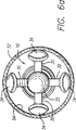
【図2a】 図2の2a−2a線におけるカテーテルの第1の実施形態の作動端の端面図である。
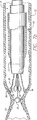
【図3】 完全引っ込め位置にある電極を示す本発明によるカテーテルの第1の実施形態の作動端の横断面図である。
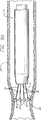
【図4】 完全伸ばし位置にある電極を示す本発明の原理によるカテーテルの第2の実施形態の作動端の横断面図である。
【図4a】 図4の4a−4a線におけるカテーテルの第2の実施形態の作動端の端面図である。
【図5】 完全引っ込め位置にある電極を示す図4のテーテルの第2の実施形態の作動端の横断面図である。
【図6a】 図6の6a−6a線におけるカテーテルを収容した解剖構造体の横断面図である。
【図7a】 本発明の第1の実施形態によるカテーテルを収容し、結紮の種々の段階における解剖構造体を示す解剖構造体の横断面図である。
【図7b】 本発明の第1の実施形態によるカテーテルを収容し、結紮の種々の段階における解剖構造体を示す解剖構造体の横断面図である。
【図7c】 本発明の第1の実施形態によるカテーテルを収容し、結紮の種々の段階における解剖構造体を示す解剖構造体の横断面図である。
【図8】 図4に示した本発明の第2の実施形態によるカテーテルを収容した解剖構造体の横断面図である。
【図8a】 図8の8a−8a線におけるカテーテルを収容した解剖構造体の横断面図である。
【図9a】 本発明の第2の実施形態によるカテーテルを収容し、結紮の種々の段階における解剖構造体を示す解剖構造体の横断面図である。
【図9b】 本発明の第2の実施形態によるカテーテルを収容し、結紮の種々の段階における解剖構造体を示す解剖構造体の横断面図である。
【図9c】 本発明の第2の実施形態によるカテーテルを収容し、結紮の種々の段階における解剖構造体を示す解剖構造体の横断面図である。
【図10】完全伸ばし位置にある電極を示す本発明によるカテーテルの第3の実施形態の作動端の横断面図である。
【図10a】 図10の10a−10a線におけるカテーテルの第3の実施形態の作動端の端面図である。
【図11】 完全引っ込め位置にある電極を示す本発明によるカテーテルの第3の実施形態の作動端の横断面図である。
【図12】 電極を解剖構造体と並置して図10のカテーテルを収容した解剖構造体の横断面図である。
【図13】 解剖構造体が電極からエネルギーを付与することによって結紮されている図10のカテーテルを収容した解剖構造体の横断面図である。
【図14】 電極を解剖構造体と並置し、構造体を結紮するために電極からエネルギーを付与する前に中空構造体の径を小さくするように外部的な圧縮が付与されている図10のカテーテルを収容した解剖構造体の横断面図である。
【図15】 バルーンおよび同軸流体チャンネルを有する電極カテーテルのもう1つの実施形態の側面図である。
【図16】 図15のバルーンおよびカテーテルの部分横断面図である。
【図17】 バルーンおよび電極を備えた曲げ可能なアームを有するカテーテルのもう1つの実施形態を収容した解剖構造体の横断面図である。
【図18】 カテーテルから外方に伸ばされた電極の小枝のように広がったリード線の間隔を隔てるカバーを有する電極カテーテルのもう1つの実施形態の側面図である。
【図19】 バルーンおよび同軸流体チャンネルを有する電極カテーテルのもう1つの実施形態の側面図である。
【図20】 バルーンおよび同軸流体チャンネルを有する電極カテーテルのもう1つの実施形態の側面図である。
【図21】 拡張可能な部分を有する電極カテーテルのもう1つの実施形態の部分横断面側面図である。
【図22】 拡張状態にある図21の電極カテーテルの実施形態の部分横断面側面図である。[0001]
Background of the Invention
The present invention relates generally to a method and apparatus for applying energy to contract a hollow anatomical structure such as a vein, and more particularly, using an electrode device having multiple leads to apply the energy. Relates to a method and apparatus.
[0002]
The human limb venous system consists essentially of the superficial venous system and the deep venous system, with the penetrating vein connecting these two venous systems. The superficial venous system includes long or large saphenous veins and short saphenous veins. The deep venous system includes an anterior tibial vein and a posterior tibial vein, which together form a popliteal vein, and when the popliteal vein is joined by a short saphenous vein, the femoral vein It becomes.
[0003]
The venous system includes a number of one-way valves for directing blood flow back to the heart. The venous valve is usually a bicuspid valve, with each cusp forming a blood sac or reservoir, which, under retrograde blood pressure, presses against the free surface of the cusp to reverse blood flow. And only allow retrograde blood flow to the heart. When the insufficiency valve is in the flow path, the valve cannot close because the cusps do not form the correct seal and cannot stop the backflow of blood. When a venous valve becomes dysfunctional, large strains and pressures are generated within the lower venous portion and the tissue overlying it, sometimes resulting in additional valve failure. Two venous conditions that often arise from valve failure are dilated tortuous veins and the more symptomatic chronic venous failure.
[0004]
Dilated serpentine veins include dilation of the superficial veins of the lower limbs and serpentine, resulting in unsightly discoloration, pain, swelling, and sometimes ulcers. Dilated serpentine veins often involve the failure of one or more venous valves that regurgitate blood within the superficial venous system. This may also exacerbate deep vein reflux and penetrating vein reflux. Current therapies for valve failure include surgical procedures such as vein removal, ligation, and sometimes vascular grafts.
[0005]
Ligation involves coagulation of the vessel lumen using electrical energy imparted by the electrode device. The electrode device is introduced into the venous lumen and positioned so that the electrode device contacts the vein wall. Once properly positioned, RF energy is applied to the electrodes, thereby causing the vein wall to contract in cross-sectional diameter. For example, a reduction in cross-sectional diameter of 5 mm (0.2 inch) to 1 mm (0.04 inch) significantly reduces blood flow through the vein and produces effective ligation. Although not required for effective ligation, the vein wall may collapse completely, thereby creating a complete luminal occlusion that prevents blood flow through the vein.
[0006]
One device for performing venous ligation includes a tubular shaft having an electrode device attached to a distal tip. An electrical lead extends from the distal end to the proximal end through the shaft. At the proximal end of the shaft, the lead terminates in an electrical connector and at the distal end of the shaft, the lead is connected to an electrode device. The electrical connector provides an interface between the lead and a power source, typically an RF generator. The RF generator is operated by the guidance of a control device, usually a microprocessor.
[0007]
The ligating device can be operated in either a monopolar configuration or a bipolar configuration. In the monopolar form, the electrode device consists of an electrode charged either positively or negatively. A current return path through the electrodes is created outside the body, for example by placing the patient in physical contact with a large low impedance pad. Current flows from the ligating device to the low impedance pad. In the bipolar configuration, the electrode device consists of a pair of oppositely charged electrodes separated by a dielectric material. Thus, in bipolar mode, the current return path is created by the electrode itself. Current flows from one electrode through the tissue and returns via the oppositely charged electrode.
[0008]
A temperature sensing device is attached to the electrode device to protect the tissue from damage, i.e., carbonization due to coagulation caused by overheating. The temperature sensing device may be a thermocouple that monitors the temperature of the venous tissue. The thermocouple interfaces with the RF generator and the controller via the shaft and applies an electrical signal to the controller, which monitors the temperature and accordingly energizes the energy applied to the tissue via the electrodes. Adjust.
[0009]
The overall effect of the ligation device depends largely on the electrode device housed in the ligation device. Monopolar and bipolar electrode devices consisting of solid devices having a constant shape and dimensions limit the effectiveness of the ligation device for several reasons. First, a fixed size electrode typically contacts the vein wall only at one point around the vein wall, ie, the inner diameter. As a result, the application of RF energy is largely concentrated in the venous tissue that is in contact, while the flow of RF current through the rest of the venous tissue is disproportionately weak. Thus, the region of the vein wall near the point of contact collapses at a faster rate than other regions of the vein, causing uneven contraction of the venous lumen. In addition, the overall strength of the occlusion may be insufficient and eventually the lumen may reopen. In order to avoid inadequate occlusion, RF energy must be applied for a long time. Such application of RF energy raises the temperature of the blood and usually produces a significant amount of undesired heat-induced coagulation on the electrodes and in the veins.
[0010]
Secondly, the effect of a ligation device with a fixed electrode device is limited to several sized veins. Attempting to ligate a vein having a diameter substantially larger than the electrode device not only causes non-uniform contraction of the vein as described above, but may result in insufficient contraction of the vein. The larger the diameter of the blood vessel relative to the diameter of the electrode device, the less energy is applied to the vein wall at a point farther from the contact point. Thus, the venous wall tends not to collapse completely until the venous tissue becomes excessively coagulated at the electrode contact points.
[0011]
Such clotting may initially occlude the blood vessel, but such occlusion is only temporary because the coagulated blood will eventually dissolve and the blood vessel may partially reopen. There may not be. One solution to this deficiency is a device with compatible electrode devices with various diameters. However, such a solution is economically insufficient and is time consuming and tiresome to use.
[0012]
Thus, those skilled in the art can distribute RF energy evenly along the peripheral band of the vein when the vein is larger in diameter than the electrode device, thereby providing a more predictable and effective vein occlusion. And a need has been recognized for an expandable electrode device and method that can minimize the formation of thermally induced coagulation. The present invention satisfies these needs and others.
[0013]
SUMMARY OF THE INVENTION
Briefly and in general terms, the present invention provides an apparatus and method for applying energy along a generally circumferential bend of a vein wall. This application of energy results in a uniform and predictable contraction of the vein wall.
[0014]
In one aspect of the invention, an apparatus for delivering energy to master an anatomical structure is disposed within a sheath, a catheter having a sheath, a working end, and an opening formed in the working end. An inner member and a plurality of leads, each having a distal end, wherein the inner member and the sheath can be moved relative to each other, the plurality of leads being positioned on the inner member in one direction of the sheath. When coupled to the inner member such that the distal ends of the plurality of leads extend out of the opening at the working end of the catheter, each lead has a plurality of leads extending out of the opening. The distal end of the lead is configured to deliver energy to the anatomical structure when the distal end is moved away from the longitudinal axis defined by the sheath.
[0015]
In another aspect of the invention, the device includes a secondary lead having a secondary distal end. The secondary lead and the inner member such that when the sheath position changes relative to the inner member in one direction, the distal ends of the plurality of secondary leads are extended out of the opening at the working end of the catheter. Combined.
[0016]
In another aspect of the invention, the distal end of the lead is electrically connected to a power supply so that the polarity of each lead can be switched. If there is a secondary lead wire electrode, the plurality of lead wires can be connected to a power source so that the polarity of the lead wire can be changed regardless of the polarity of the secondary lead wire.
[0017]
In other aspects, the lead includes a primary lead that substantially surrounds the secondary lead at the working end of the catheter. The distal end of the primary lead is placed between the distal end of the secondary lead and the inner member.
[0018]
In yet another aspect, the present invention includes a method for applying energy to a hollow anatomical structure from within the anatomical structure. The method includes introducing a catheter into the anatomical structure, the catheter having an active end and a plurality of leads, each lead having a distal end, and each lead being connected to a power source. The method also includes expanding the lead outward through the distal orifice and expanding the lead until each electrode contacts the anatomical structure. The method further includes applying energy from the distal end of the lead to the anatomical structure until the anatomical structure is collapsed.
[0019]
In another aspect of the invention, the method also includes introducing a catheter into the anatomical structure, the catheter having a distal portion having a length greater than the distal portion of the primary lead and the primary lead. It has a secondary lead that is substantially surrounded by the wire. The secondary lead also has an electrode at the distal end. This method also extends the primary and secondary leads through the orifice until each primary lead electrode contacts the anatomical structure, maintaining the secondary lead such that the secondary lead is electrically neutral. While controlling the power supply so that adjacent primary leads are of opposite polarity. When the anatomical structure is collapsed around the primary lead, the polarity of the primary lead is switched so that the primary leads are all of the same polarity. When switching the polarity of the primary lead wire so that it has the same polarity as the primary lead wire drawing, this method involves controlling the power supply to be of the opposite polarity to the secondary lead wire or the primary lead wire. including.
In a further aspect, the method includes moving the catheter through the anatomical structure while continuing to apply energy to the anatomical structure to lengthen the ligation area.
[0020]
In another aspect of the invention, external compression is used to initially force the vein wall to collapse towards the catheter. The application of energy shapes the veins to permanently exhibit a collapsed state that is initially mechanically achieved by opening compression. A tourniquet can be used to externally compress or flatten the anatomical structure and initially reduce the diameter of the hollow anatomical structure. The pressure applied by the tourniquet can exhale blood from the venous treatment site, and the veins can be pre-formed in preparation for shaping into a ligated state. An ultrasound window formed in the tourniquet can be used to facilitate ultrasound images of the anatomical structure being treated through the window.
[0021]
In yet another aspect of the present invention, a balloon is provided that closes the vein prior to energy application, so that the need for external compression with a tourniquet is not required to stop the blood flow. As a result, even for deep veins where the compressible tourniquet cannot compress the veins until they are closed, the veins can be closed.
[0022]
In yet another aspect of the invention, when the lead is extended outward, a flexible sheath that is relatively impermeable to fluid extends to the area between the leads along the circumference of the catheter, and the web-type sheath is intravenous. Blocks blood flow.
[0023]
In yet another aspect of the invention, a flexible balloon-like cover is disposed on the catheter, the cover having an opening to the concave side, with the convex side facing the working end of the catheter. The covering fills and expands with blood. Blood flow is stopped when the covering expands to the diameter of the vein.
[0024]
In another aspect of the present invention, mechanical blocking of blood flow with a catheter is combined with infusion of high impedance fluid. The fluid should also be an anticoagulant. The fluid moves the remaining blood from the venous treatment site and prevents energy from escaping from the veins juxtaposed with the electrodes.
[0025]
These and other aspects and advantages of the present invention will become apparent from the following detailed description when read in conjunction with the accompanying drawings, which illustrate, by way of example, embodiments of the invention.
[0026]
DETAILED DESCRIPTION OF THE INVENTION
Turning now in more detail to the drawing in which the same reference numerals indicate the same or corresponding elements, FIG. 1 shows a
[0027]
The
[0028]
In one embodiment, the
[0029]
Referring now to FIGS. 2, 2 a, 3, 4, 4 a and 5, the
[0030]
[0031]
The insulation of each of the
[0032]
An
[0033]
In the embodiment of the invention shown in FIGS. 2, 2a and 3, the
[0034]
FIG. 3 shows the
[0035]
4 and 5, in another embodiment, the
[0036]
In the above embodiment, the primary leads 30 are formed away, for example, arced or bent so as to avoid contact. The “distal portion” of the
[0037]
Other techniques for expanding such leads outward as soon as they are extended at the working end of the catheter may be possible. For example, the lead wires are straight, but may be attached to the alignment device at an angle such that these lead wires are always directed outward.
[0038]
To increase the juxtaposition force, the
[0039]
The length of the distal portion of
[0040]
Different numbers of
[0041]
Then, referring again to FIG. 1, the
[0042]
Referring again to FIGS. 2, 2a, 3, 4, 4a and 5, the
[0043]
With reference to FIGS. 6, 6a and FIGS. 7a-7c, during operation of one embodiment of the
[0044]
Using fluoroscopy, ultrasound and angiographic imaging techniques, or other techniques, a specific position of the catheter may be directed and further confirmed in the vein. The actuator (not shown) is then actuated to retract the
When
[0045]
In bipolar operation, the
The catheter is then withdrawn while energy is applied to the electrode device. As shown in FIG. 7b, the
In either bipolar or monopolar operation, the addition of RF energy is distributed approximately symmetrically through the vein wall regardless of the diameter of the
[0046]
Fluid may be delivered before and during RF heating of the vein being treated through a coaxial channel formed between the
[0047]
Referring to FIGS. 8, 8 a, 9 a, and 9 b, the catheter may be used with the
[0048]
The actuator 25 (FIG. 1) is then manipulated to pull the
When the
[0049]
Where the catheter includes a fluid delivery lumen (not shown), fluid may be delivered before and during RF heating of the vein being treated. Fluid can also be moved from the treatment site within the vein to avoid blood clumping. The fluid may be a dielectric medium. The fluid may include an anticoagulant such as heparin that can prevent the blood from clotting chemically at the treatment site.
[0050]
After completing the treatment for the selected venous portion, the actuator leads the primary lead back into the
[0051]
Another embodiment of the catheter is shown in FIG. An inner member or
[0052]
Preferably, a plurality of primary leads 30 having a flat rectangular strip shape and capable of acting as an arm surround the
[0053]
The ring and primary lead are attached together so that the ring forms a base and the rectangular primary lead acts as a cantilever that operates as a cantilever arm.
[0054]
The distal end of the
[0055]
The
[0056]
A fluid port (not shown) may be in communication with the interior of the
[0057]
The
[0058]
Although not shown, it will be appreciated that the
[0059]
Referring now to FIGS. 12-14, operation of one embodiment of
[0060]
When the
[0061]
The RF energy creates a thermal effect that causes the venous tissue to contract and reduce the diameter of the vein. As shown in FIG. 13, the vein wall is crushed by energy, and finally, the
[0062]
The
[0063]
In monopolar operation, the
[0064]
In either bipolar or monopolar operation, the application of RF energy is distributed substantially symmetrically across the vein wall. As mentioned above, the electrodes should be spaced only 4 or 5 mm along the circumference of the vein, which defines the target vein diameter of the designed electrode catheter. When the electrodes are substantially equally spaced in a substantially symmetric arrangement and the spacing between the electrodes is maintained, a symmetric distribution of RF energy results in predictability and uniformity of contraction and closure strength. Increase.
[0065]
As shown in FIG. 14, after the
[0066]
The reduction in the diameter of the vein assists in preforming the vein and prepares the vein to be shaped into a ligature. The use of an external tourniquet also exhales the vein and pushes the blood away from the treatment site. Blood coagulation during the procedure is avoided by this procedure. Energy is applied from the electrode to the exsanguinated vein, which is formed to a sufficiently reduced diameter to achieve ligation. External tourniquets may be left in place to aid recovery.
[0067]
The catheter may be withdrawn during application of RF energy to ligate a long section of the vein. Then, instead of a single point with a reduced vein diameter, a long section of the vein is painted with RF energy from the catheter. Retracting the catheter in this manner creates a long closure that is difficult to recanalize. The combined use of primary and secondary electrodes effectively reduces the diameter over the long vein length. The catheter can be moved while the tourniquet compresses the vein, after which the tourniquet is removed.
[0068]
If the catheter includes a fluid delivery lumen, fluid can be delivered to the vein before RF energy is applied to the vein. Even after the tourniquet compresses the vein, the delivered fluid moves the blood away from the treatment site to ensure that no blood is present at the treatment site.
[0069]
If the tourniquet is an inflatable bladder with a window through which ultrasound passes, an ultrasonic transducer can be used to monitor vein flattening due to the compressive force imparted by the inflating bladder, or reduction in vein diameter. used. The window can be formed from polyurethane or a stand-off gel housed between polyurethane bags. The gel can be applied to the window to facilitate ultrasound imaging of the veins with the transducer. Ultrasonic visualization through the window allows the operator to look for the desired venous treatment area and to determine when the vein is effectively ligated or closed. Ultrasound visualization helps to monitor any pre-formation of the veins in preparation for shaping into a ligated state due to the thermal effects caused by the RF energy from the electrodes.
[0070]
After completing the treatment for the selected vein portion, the
[0071]
In another embodiment, as shown in FIG. 15, the
[0072]
The fluid 61 can be pumped after inflation of the
[0073]
A partial cross section of this embodiment is shown in FIG. An inflation sheath 70 surrounds the
[0074]
As shown in FIG. 17, in the embodiment, the
[0075]
As shown in FIG. 18, in another embodiment, a
[0076]
In the embodiment shown in FIG. 19, the parachute shaped
[0077]
In the embodiment shown in FIG. 20, the
[0078]
In the embodiment shown in the cross-sectional view of FIG. 21, the
[0079]
The above description of the components relates to a venous catheter having a size in the range of 2 mm (0.8 inch) to 13 mm (0.51 inch) in diameter. Of course, these diameters do not limit the scope of the invention, but are merely exemplary. The dimensions of these components may be varied to shape the
[0080]
Although described above as being positively charged, negatively charged, or as a positive or negative conductor, these terms are used for illustrative purposes only. These terms are meant to refer generally to different electrode potentials and are not intended to indicate that a particular voltage is positive or negative. In addition, other types of energy, such as light energy from optical fibers, may be used to produce a thermal effect on the hollow anatomy undergoing treatment.
[0081]
While several specific forms of the invention have been illustrated and described, it will be apparent that various changes can be made without departing from the spirit and scope of the invention. Accordingly, the invention is not limited except as by the appended claims.
[Brief description of the drawings]
FIG. 1 is a schematic diagram of an energy delivery system with a partial cutaway view of a catheter showing both working and connecting ends and incorporating a preferred embodiment of the present invention.
FIG. 2 is a cross-sectional view of the working end of the first embodiment of the catheter according to the present invention showing the electrode in a fully extended position.
2a is an end view of the working end of the first embodiment of the catheter at line 2a-2a in FIG. 2; FIG.
FIG. 3 is a cross-sectional view of the working end of the first embodiment of the catheter according to the present invention showing the electrode in a fully retracted position.
FIG. 4 is a cross-sectional view of the working end of a second embodiment of a catheter according to the principles of the present invention showing the electrode in a fully extended position.
4a is an end view of the working end of the second embodiment of the catheter at line 4a-4a in FIG. 4; FIG.
5 is a cross-sectional view of the working end of the second embodiment of the teter of FIG. 4 showing the electrode in a fully retracted position.
6a is a cross-sectional view of an anatomical structure containing a catheter taken along line 6a-6a in FIG. 6;
7a is a cross-sectional view of an anatomical structure containing a catheter according to a first embodiment of the present invention and showing the anatomical structure at various stages of ligation. FIG.
7b is a cross-sectional view of an anatomical structure containing a catheter according to a first embodiment of the present invention and showing the anatomical structure at various stages of ligation. FIG.
7c is a cross-sectional view of an anatomical structure containing a catheter according to a first embodiment of the present invention and showing the anatomical structure at various stages of ligation. FIG.
FIG. 8 is a cross-sectional view of an anatomical structure containing a catheter according to the second embodiment of the present invention shown in FIG. 4;
8a is a cross-sectional view of an anatomical structure containing a catheter taken along line 8a-8a of FIG.
FIG. 9a is a cross-sectional view of an anatomical structure containing a catheter according to a second embodiment of the present invention and showing the anatomical structure at various stages of ligation.
9b is a cross-sectional view of an anatomical structure containing a catheter according to a second embodiment of the present invention and showing the anatomical structure at various stages of ligation.
9c is a cross-sectional view of an anatomical structure containing a catheter according to a second embodiment of the present invention and showing the anatomical structure at various stages of ligation. FIG.
FIG. 10 is a cross-sectional view of the working end of a third embodiment of the catheter according to the present invention showing the electrode in a fully extended position.
10a is an end view of the working end of the third embodiment of the catheter at line 10a-10a in FIG. 10;
11 is a cross-sectional view of the working end of a third embodiment of the catheter according to the present invention showing the electrode in a fully retracted position. FIG.
12 is a cross-sectional view of an anatomical structure containing the catheter of FIG. 10 with electrodes juxtaposed with the anatomical structure.
13 is a cross-sectional view of an anatomical structure containing the catheter of FIG. 10 in which the anatomical structure is ligated by applying energy from an electrode.
FIG. 14 juxtaposes the electrode with the anatomical structure and applies external compression to reduce the diameter of the hollow structure before applying energy from the electrode to ligate the structure. It is a cross-sectional view of the anatomical structure which accommodated the catheter.
FIG. 15 is a side view of another embodiment of an electrode catheter having a balloon and a coaxial fluid channel.
16 is a partial cross-sectional view of the balloon and catheter of FIG.
FIG. 17 is a cross-sectional view of an anatomical structure containing another embodiment of a catheter having a bendable arm with a balloon and electrodes.
FIG. 18 is a side view of another embodiment of an electrode catheter having a cover separating spaced lead wires extending like a twig of electrode extending outwardly from the catheter.
FIG. 19 is a side view of another embodiment of an electrode catheter having a balloon and a coaxial fluid channel.
FIG. 20 is a side view of another embodiment of an electrode catheter having a balloon and a coaxial fluid channel.
FIG. 21 is a partial cross-sectional side view of another embodiment of an electrode catheter having an expandable portion.
22 is a partial cross-sectional side view of the embodiment of the electrode catheter of FIG. 21 in an expanded state.
Claims (17)
遠位先端を有し、該遠位先端にオリフィスを形成した作動端を有するカテーテルと、
作動端に配置され、各々絶縁されてない遠位端を有する遠位部分を有し、電源に電気的に接続されるようになった複数のリード線と、
リード線を遠位オリフィスを通して延ばすための手段と、
リード線が延ばされたとき前記内壁と非貫通接触させるべくリード線の遠位端を外方に拡張させるための手段と、を含み、
前記拡張手段は各リード線に形成された曲がり又は弧を含み、リード線は、遠位オリフィスの外に延ばされたとき互に離れて解剖構造体と接触する、前記装置。A device for applying energy from a power source to a hollow anatomical structure having an inner wall,
A catheter having a distal tip and an working end having an orifice formed in the distal tip;
A plurality of leads disposed at the working end, each having a distal portion with a non-insulated distal end, adapted to be electrically connected to a power source;
Means for extending the lead through the distal orifice;
Means for expanding the distal end of the lead wire outwardly in non-penetrating contact with the inner wall when the lead wire is extended;
The apparatus, wherein the expansion means includes a bend or arc formed in each lead, the leads being in contact with the anatomical structure apart from each other when extended out of the distal orifice.
コントローラは、リード線の遠位端の電気極性を共通の極性に切り換え、又二次リード線の極性をリード線の極性と反対の極性に切り換えるようになっている、請求項9に記載の装置。A controller for controlling the output of the power supply to the lead and the secondary lead;
The apparatus of claim 9, wherein the controller is configured to switch the electrical polarity of the distal end of the lead to a common polarity and to switch the polarity of the secondary lead to a polarity opposite to the polarity of the lead. .
整列装置と関係して外側シースを移動させることによりリード線をオリフィスを通して延ばす請求項1に記載の装置。Means for extending includes an outer sheath movable on the catheter and an alignment device positioned within the outer sheath to maintain separation between the leads;
The apparatus of claim 1 wherein the lead is extended through the orifice by moving the outer sheath relative to the alignment device.
外側シース内に位置決めされた整列装置とを、含み、リード線は、整列装置がリード線間の分離を維持するように整列装置に取付けられ、
リード線を取付ける可動の内側シースを有し、該内側シースは外側シースと関係して移動でき、
外側シースと関係して内側シースを移動させることによりリード線をオリフィスを通して延ばす、請求項1に記載の装置。Means for extending the outer sheath provided on the catheter;
An alignment device positioned within the outer sheath, wherein the lead is attached to the alignment device such that the alignment device maintains a separation between the leads.
A movable inner sheath for attaching a lead, the inner sheath being movable relative to the outer sheath;
The apparatus of claim 1, wherein the lead is extended through the orifice by moving the inner sheath relative to the outer sheath.
コントローラは温度センサーからの信号に応答して電源を制御する、請求項1に記載の装置。A controller for controlling the power supply; and a temperature sensor provided at the distal end of the lead and providing a temperature signal to the controller;
The apparatus of claim 1, wherein the controller controls the power supply in response to a signal from the temperature sensor.
Applications Claiming Priority (5)
| Application Number | Priority Date | Filing Date | Title |
|---|---|---|---|
| US08/927,251 | 1997-09-11 | ||
| US08/927,251 US6200312B1 (en) | 1997-09-11 | 1997-09-11 | Expandable vein ligator catheter having multiple electrode leads |
| US08/958,766 US6165172A (en) | 1997-09-11 | 1997-10-26 | Expandable vein ligator catheter and method of use |
| US08/958,766 | 1997-10-26 | ||
| PCT/US1998/019181 WO1999012489A2 (en) | 1997-09-11 | 1998-09-11 | Expandable vein ligator catheter and method of use |
Publications (3)
| Publication Number | Publication Date |
|---|---|
| JP2001515752A JP2001515752A (en) | 2001-09-25 |
| JP2001515752A5 JP2001515752A5 (en) | 2006-01-05 |
| JP4131609B2 true JP4131609B2 (en) | 2008-08-13 |
Family
ID=27129940
Family Applications (1)
| Application Number | Title | Priority Date | Filing Date |
|---|---|---|---|
| JP2000510391A Expired - Fee Related JP4131609B2 (en) | 1997-09-11 | 1998-09-11 | Expandable venous ligation catheter |
Country Status (13)
| Country | Link |
|---|---|
| US (6) | US6401719B1 (en) |
| EP (1) | EP1035796A2 (en) |
| JP (1) | JP4131609B2 (en) |
| CN (1) | CN1154447C (en) |
| AU (1) | AU740000B2 (en) |
| BR (1) | BR9814738A (en) |
| CA (1) | CA2303021C (en) |
| IL (1) | IL135008A0 (en) |
| NO (1) | NO328108B1 (en) |
| NZ (1) | NZ503367A (en) |
| PL (1) | PL339518A1 (en) |
| RU (1) | RU2207822C2 (en) |
| WO (1) | WO1999012489A2 (en) |
Families Citing this family (272)
| Publication number | Priority date | Publication date | Assignee | Title |
|---|---|---|---|---|
| US6176240B1 (en) | 1995-06-07 | 2001-01-23 | Conceptus, Inc. | Contraceptive transcervical fallopian tube occlusion devices and their delivery |
| US6705323B1 (en) | 1995-06-07 | 2004-03-16 | Conceptus, Inc. | Contraceptive transcervical fallopian tube occlusion devices and methods |
| WO1997032532A1 (en) * | 1996-03-05 | 1997-09-12 | Vnus Medical Technologies, Inc. | Vascular catheter-based system for heating tissue |
| US7604633B2 (en) | 1996-04-12 | 2009-10-20 | Cytyc Corporation | Moisture transport system for contact electrocoagulation |
| US5957920A (en) * | 1997-08-28 | 1999-09-28 | Isothermix, Inc. | Medical instruments and techniques for treatment of urinary incontinence |
| WO1998038936A1 (en) | 1997-03-04 | 1998-09-11 | Vnus Medical Technologies, Inc. | Method and apparatus for treating venous insufficiency using directionally applied energy |
| AU758284B2 (en) * | 1997-06-05 | 2003-03-20 | Adiana, Inc. | Method and apparatus for tubal occlusion |
| US6258084B1 (en) * | 1997-09-11 | 2001-07-10 | Vnus Medical Technologies, Inc. | Method for applying energy to biological tissue including the use of tumescent tissue compression |
| US6200312B1 (en) * | 1997-09-11 | 2001-03-13 | Vnus Medical Technologies, Inc. | Expandable vein ligator catheter having multiple electrode leads |
| US6179832B1 (en) * | 1997-09-11 | 2001-01-30 | Vnus Medical Technologies, Inc. | Expandable catheter having two sets of electrodes |
| US6401719B1 (en) * | 1997-09-11 | 2002-06-11 | Vnus Medical Technologies, Inc. | Method of ligating hollow anatomical structures |
| US8551082B2 (en) | 1998-05-08 | 2013-10-08 | Cytyc Surgical Products | Radio-frequency generator for powering an ablation device |
| US6740082B2 (en) * | 1998-12-29 | 2004-05-25 | John H. Shadduck | Surgical instruments for treating gastro-esophageal reflux |
| US6889089B2 (en) * | 1998-07-28 | 2005-05-03 | Scimed Life Systems, Inc. | Apparatus and method for treating tumors near the surface of an organ |
| US6309384B1 (en) * | 1999-02-01 | 2001-10-30 | Adiana, Inc. | Method and apparatus for tubal occlusion |
| US8702727B1 (en) | 1999-02-01 | 2014-04-22 | Hologic, Inc. | Delivery catheter with implant ejection mechanism |
| US8285393B2 (en) * | 1999-04-16 | 2012-10-09 | Laufer Michael D | Device for shaping infarcted heart tissue and method of using the device |
| US6375668B1 (en) * | 1999-06-02 | 2002-04-23 | Hanson S. Gifford | Devices and methods for treating vascular malformations |
| US6709667B1 (en) * | 1999-08-23 | 2004-03-23 | Conceptus, Inc. | Deployment actuation system for intrafallopian contraception |
| US8241274B2 (en) | 2000-01-19 | 2012-08-14 | Medtronic, Inc. | Method for guiding a medical device |
| US6595950B1 (en) * | 2000-05-11 | 2003-07-22 | Zevex, Inc. | Apparatus and method for preventing free flow in an infusion line |
| US7150727B2 (en) * | 2000-05-11 | 2006-12-19 | Zevex, Inc. | Apparatus and method for preventing free flow in an infusion line |
| US7815612B2 (en) | 2000-05-11 | 2010-10-19 | Zevex, Inc. | Apparatus and method for preventing free flow in an infusion line |
| US7077836B2 (en) * | 2000-07-21 | 2006-07-18 | Vein Rx, Inc. | Methods and apparatus for sclerosing the wall of a varicose vein |
| US20050113798A1 (en) * | 2000-07-21 | 2005-05-26 | Slater Charles R. | Methods and apparatus for treating the interior of a blood vessel |
| US20030120256A1 (en) * | 2001-07-03 | 2003-06-26 | Syntheon, Llc | Methods and apparatus for sclerosing the wall of a varicose vein |
| US20050107738A1 (en) * | 2000-07-21 | 2005-05-19 | Slater Charles R. | Occludable intravascular catheter for drug delivery and method of using the same |
| DE10042493A1 (en) | 2000-08-30 | 2002-03-14 | Ethicon Endo Surgery Europe | System for treating varicose veins |
| US6620128B1 (en) * | 2000-10-20 | 2003-09-16 | Advanced Cardiovascular Systems, Inc. | Balloon blowing process with metered volumetric inflation |
| AU2002239929A1 (en) * | 2001-01-16 | 2002-07-30 | Novacept | Apparatus and method for treating venous reflux |
| CN100450456C (en) * | 2001-09-28 | 2009-01-14 | 锐达医疗系统公司 | Impedance controlled tissue ablation apparatus and method |
| US6669693B2 (en) * | 2001-11-13 | 2003-12-30 | Mayo Foundation For Medical Education And Research | Tissue ablation device and methods of using |
| US6736822B2 (en) * | 2002-02-20 | 2004-05-18 | Mcclellan Scott B. | Device and method for internal ligation of tubular structures |
| US7756583B2 (en) | 2002-04-08 | 2010-07-13 | Ardian, Inc. | Methods and apparatus for intravascularly-induced neuromodulation |
| US7617005B2 (en) | 2002-04-08 | 2009-11-10 | Ardian, Inc. | Methods and apparatus for thermally-induced renal neuromodulation |
| US8347891B2 (en) | 2002-04-08 | 2013-01-08 | Medtronic Ardian Luxembourg S.A.R.L. | Methods and apparatus for performing a non-continuous circumferential treatment of a body lumen |
| US8150519B2 (en) | 2002-04-08 | 2012-04-03 | Ardian, Inc. | Methods and apparatus for bilateral renal neuromodulation |
| US6780182B2 (en) * | 2002-05-23 | 2004-08-24 | Adiana, Inc. | Catheter placement detection system and operator interface |
| IE20040042A1 (en) * | 2003-01-31 | 2004-08-25 | Preton Ltd | A process for producing a performance enhanced single-layer blow-moulded container |
| US7223266B2 (en) * | 2003-02-04 | 2007-05-29 | Cardiodex Ltd. | Methods and apparatus for hemostasis following arterial catheterization |
| US7115127B2 (en) | 2003-02-04 | 2006-10-03 | Cardiodex, Ltd. | Methods and apparatus for hemostasis following arterial catheterization |
| US8021359B2 (en) | 2003-02-13 | 2011-09-20 | Coaptus Medical Corporation | Transseptal closure of a patent foramen ovale and other cardiac defects |
| JP4382087B2 (en) * | 2003-03-27 | 2009-12-09 | テルモ株式会社 | Method and apparatus for treatment of patent foramen ovale |
| US7293562B2 (en) * | 2003-03-27 | 2007-11-13 | Cierra, Inc. | Energy based devices and methods for treatment of anatomic tissue defects |
| EP3045136B1 (en) | 2003-09-12 | 2021-02-24 | Vessix Vascular, Inc. | Selectable eccentric remodeling and/or ablation of atherosclerotic material |
| DE10345023A1 (en) * | 2003-09-24 | 2005-04-21 | Biotronik Gmbh & Co Kg | Ablation catheter, comprising electrode holding elements in radial extended position when released |
| US7431717B2 (en) * | 2003-09-30 | 2008-10-07 | Serene Medical, Inc. | Central nervous system administration of medications by means of pelvic venous catheterization and reversal of Batson's Plexus |
| US20050107867A1 (en) * | 2003-11-17 | 2005-05-19 | Taheri Syde A. | Temporary absorbable venous occlusive stent and superficial vein treatment method |
| US20050137646A1 (en) * | 2003-12-22 | 2005-06-23 | Scimed Life Systems, Inc. | Method of intravascularly delivering stimulation leads into brain |
| US8060207B2 (en) * | 2003-12-22 | 2011-11-15 | Boston Scientific Scimed, Inc. | Method of intravascularly delivering stimulation leads into direct contact with tissue |
| US8048101B2 (en) | 2004-02-25 | 2011-11-01 | Femasys Inc. | Methods and devices for conduit occlusion |
| US9238127B2 (en) | 2004-02-25 | 2016-01-19 | Femasys Inc. | Methods and devices for delivering to conduit |
| US8048086B2 (en) | 2004-02-25 | 2011-11-01 | Femasys Inc. | Methods and devices for conduit occlusion |
| US8052669B2 (en) | 2004-02-25 | 2011-11-08 | Femasys Inc. | Methods and devices for delivery of compositions to conduits |
| DE102004015641B3 (en) * | 2004-03-31 | 2006-03-09 | Siemens Ag | Device for elimination of complete occlusion with IVUS monitoring |
| US7250050B2 (en) | 2004-06-07 | 2007-07-31 | Ethicon, Inc. | Tubal sterilization device having sesquipolar electrodes and method for performing sterilization using the same |
| US6964274B1 (en) | 2004-06-07 | 2005-11-15 | Ethicon, Inc. | Tubal sterilization device having expanding electrodes and method for performing sterilization using the same |
| US7824408B2 (en) * | 2004-08-05 | 2010-11-02 | Tyco Healthcare Group, Lp | Methods and apparatus for coagulating and/or constricting hollow anatomical structures |
| EP1781354A4 (en) * | 2004-08-19 | 2008-04-09 | Vein Rx Inc | An occludable intravascular catheter for drug delivery and method of using the same |
| US20060052822A1 (en) * | 2004-08-31 | 2006-03-09 | Mirizzi Michael S | Apparatus and material composition for permanent occlusion of a hollow anatomical structure |
| US8920414B2 (en) | 2004-09-10 | 2014-12-30 | Vessix Vascular, Inc. | Tuned RF energy and electrical tissue characterization for selective treatment of target tissues |
| US8396548B2 (en) | 2008-11-14 | 2013-03-12 | Vessix Vascular, Inc. | Selective drug delivery in a lumen |
| US9713730B2 (en) | 2004-09-10 | 2017-07-25 | Boston Scientific Scimed, Inc. | Apparatus and method for treatment of in-stent restenosis |
| US20060069303A1 (en) * | 2004-09-30 | 2006-03-30 | Couvillon Lucien A Jr | Endoscopic apparatus with integrated hemostasis device |
| US20060089637A1 (en) | 2004-10-14 | 2006-04-27 | Werneth Randell L | Ablation catheter |
| JP5068662B2 (en) | 2004-11-22 | 2012-11-07 | カーディオデックス リミテッド | Heat treatment technology for varicose veins |
| US7731712B2 (en) | 2004-12-20 | 2010-06-08 | Cytyc Corporation | Method and system for transcervical tubal occlusion |
| KR20060072734A (en) * | 2004-12-23 | 2006-06-28 | 두산인프라코어 주식회사 | Appareatus for supplying compressed air of construction heavy equipments |
| US7455670B2 (en) * | 2005-01-14 | 2008-11-25 | Co-Repair, Inc. | System and method for the treatment of heart tissue |
| US20070156210A1 (en) * | 2005-01-14 | 2007-07-05 | Co-Repair, Inc., A California Corporation | Method for the treatment of heart tissue |
| US20070156209A1 (en) * | 2005-01-14 | 2007-07-05 | Co-Repair, Inc. | System for the treatment of heart tissue |
| US7972354B2 (en) | 2005-01-25 | 2011-07-05 | Tyco Healthcare Group Lp | Method and apparatus for impeding migration of an implanted occlusive structure |
| US20080015569A1 (en) | 2005-02-02 | 2008-01-17 | Voyage Medical, Inc. | Methods and apparatus for treatment of atrial fibrillation |
| US8137333B2 (en) | 2005-10-25 | 2012-03-20 | Voyage Medical, Inc. | Delivery of biological compounds to ischemic and/or infarcted tissue |
| US8078266B2 (en) | 2005-10-25 | 2011-12-13 | Voyage Medical, Inc. | Flow reduction hood systems |
| US7860556B2 (en) | 2005-02-02 | 2010-12-28 | Voyage Medical, Inc. | Tissue imaging and extraction systems |
| US8050746B2 (en) | 2005-02-02 | 2011-11-01 | Voyage Medical, Inc. | Tissue visualization device and method variations |
| US9510732B2 (en) | 2005-10-25 | 2016-12-06 | Intuitive Surgical Operations, Inc. | Methods and apparatus for efficient purging |
| US10064540B2 (en) | 2005-02-02 | 2018-09-04 | Intuitive Surgical Operations, Inc. | Visualization apparatus for transseptal access |
| US7918787B2 (en) | 2005-02-02 | 2011-04-05 | Voyage Medical, Inc. | Tissue visualization and manipulation systems |
| US7930016B1 (en) | 2005-02-02 | 2011-04-19 | Voyage Medical, Inc. | Tissue closure system |
| US11478152B2 (en) | 2005-02-02 | 2022-10-25 | Intuitive Surgical Operations, Inc. | Electrophysiology mapping and visualization system |
| US7860555B2 (en) * | 2005-02-02 | 2010-12-28 | Voyage Medical, Inc. | Tissue visualization and manipulation system |
| ITFI20050028A1 (en) * | 2005-02-21 | 2006-08-22 | El En Spa | DEVICE, CATHETER AND METHOD FOR THE CURATIVE TREATMENT OF VARICOSE VEINS |
| US7625372B2 (en) * | 2005-02-23 | 2009-12-01 | Vnus Medical Technologies, Inc. | Methods and apparatus for coagulating and/or constricting hollow anatomical structures |
| DE102005038694A1 (en) * | 2005-04-11 | 2006-10-26 | Erbe Elektromedizin Gmbh | Endoscopic surgery device |
| US7674260B2 (en) | 2005-04-28 | 2010-03-09 | Cytyc Corporation | Emergency hemostasis device utilizing energy |
| DE102005023303A1 (en) * | 2005-05-13 | 2006-11-16 | Celon Ag Medical Instruments | Biegeweiche application device for high-frequency therapy of biological tissue |
| EP2662042A3 (en) | 2005-07-21 | 2017-03-22 | Covidien LP | Systems and methods for treating a hollow anatomical structure |
| DE202006021213U1 (en) * | 2005-07-21 | 2013-11-08 | Covidien Lp | Apparatus for treating a hollow anatomical structure |
| US7957815B2 (en) | 2005-10-11 | 2011-06-07 | Thermage, Inc. | Electrode assembly and handpiece with adjustable system impedance, and methods of operating an energy-based medical system to treat tissue |
| US8702691B2 (en) * | 2005-10-19 | 2014-04-22 | Thermage, Inc. | Treatment apparatus and methods for delivering energy at multiple selectable depths in tissue |
| US8221310B2 (en) | 2005-10-25 | 2012-07-17 | Voyage Medical, Inc. | Tissue visualization device and method variations |
| US9101742B2 (en) * | 2005-10-28 | 2015-08-11 | Baxter International Inc. | Gastrointestinal applicator and method of using same |
| US9017361B2 (en) | 2006-04-20 | 2015-04-28 | Covidien Lp | Occlusive implant and methods for hollow anatomical structure |
| US9138250B2 (en) | 2006-04-24 | 2015-09-22 | Ethicon Endo-Surgery, Inc. | Medical instrument handle and medical instrument having a handle |
| US20070250012A1 (en) * | 2006-04-24 | 2007-10-25 | Ifung Lu | Medical instrument having a medical needle-knife |
| US8211114B2 (en) | 2006-04-24 | 2012-07-03 | Ethicon Endo-Surgery, Inc. | Medical instrument having a medical snare |
| US7927327B2 (en) * | 2006-04-25 | 2011-04-19 | Ethicon Endo-Surgery, Inc. | Medical instrument having an articulatable end effector |
| US7837620B2 (en) | 2006-04-25 | 2010-11-23 | Ethicon Endo-Surgery, Inc. | Medical tubular assembly |
| US20070255312A1 (en) * | 2006-05-01 | 2007-11-01 | Ifung Lu | Medical instrument having an end-effector-associated member |
| US8019435B2 (en) | 2006-05-02 | 2011-09-13 | Boston Scientific Scimed, Inc. | Control of arterial smooth muscle tone |
| US7758593B2 (en) * | 2006-05-04 | 2010-07-20 | Ethicon Endo-Surgery, Inc. | Medical instrument handle and medical instrument having same |
| US7597661B2 (en) * | 2006-05-11 | 2009-10-06 | Ethicon Endo-Surgery, Inc. | Medical instrument having a catheter and method for using a catheter |
| US7959642B2 (en) | 2006-05-16 | 2011-06-14 | Ethicon Endo-Surgery, Inc. | Medical instrument having a needle knife |
| US7892166B2 (en) * | 2006-05-18 | 2011-02-22 | Ethicon Endo-Surgery, Inc. | Medical instrument including a catheter having a catheter stiffener and method for using |
| WO2007140331A2 (en) | 2006-05-25 | 2007-12-06 | Medtronic, Inc. | Methods of using high intensity focused ultrasound to form an ablated tissue area containing a plurality of lesions |
| US9055906B2 (en) | 2006-06-14 | 2015-06-16 | Intuitive Surgical Operations, Inc. | In-vivo visualization systems |
| US20080097476A1 (en) | 2006-09-01 | 2008-04-24 | Voyage Medical, Inc. | Precision control systems for tissue visualization and manipulation assemblies |
| JP2010502313A (en) | 2006-09-01 | 2010-01-28 | ボエッジ メディカル, インコーポレイテッド | Method and apparatus for the treatment of atrial fibrillation |
| US10004388B2 (en) | 2006-09-01 | 2018-06-26 | Intuitive Surgical Operations, Inc. | Coronary sinus cannulation |
| JP4201037B2 (en) * | 2006-09-14 | 2008-12-24 | ソニー株式会社 | Lens barrel rotation imaging device |
| US8486060B2 (en) | 2006-09-18 | 2013-07-16 | Cytyc Corporation | Power ramping during RF ablation |
| AU2007216674A1 (en) * | 2006-09-21 | 2008-04-10 | Cathrx Ltd | A catheter assembly |
| DE102006047366A1 (en) * | 2006-10-04 | 2008-04-10 | Celon Ag Medical Instruments | Flexible soft catheter for radiofrequency therapy of biological tissue |
| AU2007310991B2 (en) | 2006-10-18 | 2013-06-20 | Boston Scientific Scimed, Inc. | System for inducing desirable temperature effects on body tissue |
| ES2560006T3 (en) | 2006-10-18 | 2016-02-17 | Vessix Vascular, Inc. | Induction of desirable temperature effects on body tissue |
| US10335131B2 (en) | 2006-10-23 | 2019-07-02 | Intuitive Surgical Operations, Inc. | Methods for preventing tissue migration |
| US20090036840A1 (en) * | 2006-11-22 | 2009-02-05 | Cytyc Corporation | Atraumatic ball tip and side wall opening |
| US20100063360A1 (en) * | 2006-11-28 | 2010-03-11 | Adiana, Inc. | Side-arm Port Introducer |
| JP2008132163A (en) * | 2006-11-28 | 2008-06-12 | Olympus Medical Systems Corp | Tool for treatment of body lumen occlusion |
| US20080183036A1 (en) | 2006-12-18 | 2008-07-31 | Voyage Medical, Inc. | Systems and methods for unobstructed visualization and ablation |
| US7846160B2 (en) | 2006-12-21 | 2010-12-07 | Cytyc Corporation | Method and apparatus for sterilization |
| US8758229B2 (en) | 2006-12-21 | 2014-06-24 | Intuitive Surgical Operations, Inc. | Axial visualization systems |
| US8131350B2 (en) | 2006-12-21 | 2012-03-06 | Voyage Medical, Inc. | Stabilization of visualization catheters |
| US20080161893A1 (en) * | 2006-12-29 | 2008-07-03 | Saurav Paul | Fabric electrode head |
| US20080200873A1 (en) * | 2007-02-16 | 2008-08-21 | Alejandro Espinosa | Methods and Apparatus for Infusing the Interior of a Blood Vessel |
| AU2008245600B2 (en) * | 2007-04-27 | 2013-07-04 | Covidien Lp | Systems and methods for treating hollow anatomical structures |
| WO2008134457A1 (en) | 2007-04-27 | 2008-11-06 | Voyage Medical, Inc. | Complex shape steerable tissue visualization and manipulation catheter |
| US8579886B2 (en) * | 2007-05-01 | 2013-11-12 | Covidien Lp | Accordion style cable stand-off |
| US8657805B2 (en) * | 2007-05-08 | 2014-02-25 | Intuitive Surgical Operations, Inc. | Complex shape steerable tissue visualization and manipulation catheter |
| EP3025636B1 (en) | 2007-05-11 | 2017-11-01 | Intuitive Surgical Operations, Inc. | Visual electrode ablation systems |
| WO2009009661A1 (en) | 2007-07-10 | 2009-01-15 | Thermage, Inc. | Treatment apparatus and methods for delivering high frequency energy across large tissue areas |
| US8702609B2 (en) | 2007-07-27 | 2014-04-22 | Meridian Cardiovascular Systems, Inc. | Image-guided intravascular therapy catheters |
| EP2182875A4 (en) | 2007-08-15 | 2011-08-24 | Cardiodex Ltd | Systems and methods for puncture closure |
| EP2184019B1 (en) * | 2007-08-28 | 2015-12-09 | Terumo Kabushiki Kaisha | Device for opening/closing biological tissue |
| US8235985B2 (en) | 2007-08-31 | 2012-08-07 | Voyage Medical, Inc. | Visualization and ablation system variations |
| US20090125023A1 (en) * | 2007-11-13 | 2009-05-14 | Cytyc Corporation | Electrosurgical Instrument |
| US8292880B2 (en) | 2007-11-27 | 2012-10-23 | Vivant Medical, Inc. | Targeted cooling of deployable microwave antenna |
| US8858609B2 (en) | 2008-02-07 | 2014-10-14 | Intuitive Surgical Operations, Inc. | Stent delivery under direct visualization |
| US8157747B2 (en) | 2008-02-15 | 2012-04-17 | Lary Research & Development, Llc | Single-use indicator for a surgical instrument and a surgical instrument incorporating same |
| WO2009146045A2 (en) * | 2008-04-01 | 2009-12-03 | Zevex, Inc. | Safety occluder and method of use |
| US8425470B2 (en) | 2008-04-01 | 2013-04-23 | Zevex, Inc. | Anti-free-flow mechanism for enteral feeding pumps |
| EP2271385A4 (en) * | 2008-04-01 | 2016-10-26 | Zevex Inc | Anti-free flow mechanism for enteral feeding pumps |
| US9770297B2 (en) * | 2008-06-04 | 2017-09-26 | Covidien Lp | Energy devices and methods for treating hollow anatomical structures |
| US9101735B2 (en) | 2008-07-07 | 2015-08-11 | Intuitive Surgical Operations, Inc. | Catheter control systems |
| US9554826B2 (en) | 2008-10-03 | 2017-01-31 | Femasys, Inc. | Contrast agent injection system for sonographic imaging |
| US10070888B2 (en) | 2008-10-03 | 2018-09-11 | Femasys, Inc. | Methods and devices for sonographic imaging |
| US8333012B2 (en) | 2008-10-10 | 2012-12-18 | Voyage Medical, Inc. | Method of forming electrode placement and connection systems |
| US8894643B2 (en) | 2008-10-10 | 2014-11-25 | Intuitive Surgical Operations, Inc. | Integral electrode placement and connection systems |
| US9468364B2 (en) | 2008-11-14 | 2016-10-18 | Intuitive Surgical Operations, Inc. | Intravascular catheter with hood and image processing systems |
| WO2010056745A1 (en) | 2008-11-17 | 2010-05-20 | Minnow Medical, Inc. | Selective accumulation of energy with or without knowledge of tissue topography |
| US20100198209A1 (en) * | 2009-01-30 | 2010-08-05 | Tartaglia Joseph M | Hemorrhoid Therapy and Method |
| GB2479697B (en) | 2009-02-06 | 2013-10-09 | Zevex Inc | Automatic safety occluder |
| CN102686180B (en) * | 2009-11-04 | 2015-09-30 | 艾姆西森有限公司 | Intracavity remodeling device and method |
| US8936631B2 (en) * | 2010-01-04 | 2015-01-20 | Covidien Lp | Apparatus and methods for treating hollow anatomical structures |
| US8231619B2 (en) * | 2010-01-22 | 2012-07-31 | Cytyc Corporation | Sterilization device and method |
| US8694071B2 (en) | 2010-02-12 | 2014-04-08 | Intuitive Surgical Operations, Inc. | Image stabilization techniques and methods |
| US8728067B2 (en) * | 2010-03-08 | 2014-05-20 | Covidien Lp | Microwave antenna probe having a deployable ground plane |
| US9814522B2 (en) | 2010-04-06 | 2017-11-14 | Intuitive Surgical Operations, Inc. | Apparatus and methods for ablation efficacy |
| CA2795229A1 (en) | 2010-04-09 | 2011-10-13 | Vessix Vascular, Inc. | Power generating and control apparatus for the treatment of tissue |
| US9192790B2 (en) | 2010-04-14 | 2015-11-24 | Boston Scientific Scimed, Inc. | Focused ultrasonic renal denervation |
| US8550086B2 (en) | 2010-05-04 | 2013-10-08 | Hologic, Inc. | Radiopaque implant |
| US8473067B2 (en) | 2010-06-11 | 2013-06-25 | Boston Scientific Scimed, Inc. | Renal denervation and stimulation employing wireless vascular energy transfer arrangement |
| US9463062B2 (en) | 2010-07-30 | 2016-10-11 | Boston Scientific Scimed, Inc. | Cooled conductive balloon RF catheter for renal nerve ablation |
| US9408661B2 (en) | 2010-07-30 | 2016-08-09 | Patrick A. Haverkost | RF electrodes on multiple flexible wires for renal nerve ablation |
| US9084609B2 (en) | 2010-07-30 | 2015-07-21 | Boston Scientific Scime, Inc. | Spiral balloon catheter for renal nerve ablation |
| US9358365B2 (en) | 2010-07-30 | 2016-06-07 | Boston Scientific Scimed, Inc. | Precision electrode movement control for renal nerve ablation |
| US9155589B2 (en) | 2010-07-30 | 2015-10-13 | Boston Scientific Scimed, Inc. | Sequential activation RF electrode set for renal nerve ablation |
| USD672455S1 (en) | 2010-10-01 | 2012-12-11 | Zevex, Inc. | Fluid delivery cassette |
| EP2621560B1 (en) | 2010-10-01 | 2019-09-25 | Zevex, Inc. | Anti free-flow occluder and priming actuator pad |
| US8974451B2 (en) | 2010-10-25 | 2015-03-10 | Boston Scientific Scimed, Inc. | Renal nerve ablation using conductive fluid jet and RF energy |
| US9220558B2 (en) | 2010-10-27 | 2015-12-29 | Boston Scientific Scimed, Inc. | RF renal denervation catheter with multiple independent electrodes |
| US9028485B2 (en) | 2010-11-15 | 2015-05-12 | Boston Scientific Scimed, Inc. | Self-expanding cooling electrode for renal nerve ablation |
| US9089350B2 (en) | 2010-11-16 | 2015-07-28 | Boston Scientific Scimed, Inc. | Renal denervation catheter with RF electrode and integral contrast dye injection arrangement |
| US9668811B2 (en) | 2010-11-16 | 2017-06-06 | Boston Scientific Scimed, Inc. | Minimally invasive access for renal nerve ablation |
| US9326751B2 (en) | 2010-11-17 | 2016-05-03 | Boston Scientific Scimed, Inc. | Catheter guidance of external energy for renal denervation |
| US9060761B2 (en) | 2010-11-18 | 2015-06-23 | Boston Scientific Scime, Inc. | Catheter-focused magnetic field induced renal nerve ablation |
| US9192435B2 (en) | 2010-11-22 | 2015-11-24 | Boston Scientific Scimed, Inc. | Renal denervation catheter with cooled RF electrode |
| US9023034B2 (en) | 2010-11-22 | 2015-05-05 | Boston Scientific Scimed, Inc. | Renal ablation electrode with force-activatable conduction apparatus |
| US20120157993A1 (en) | 2010-12-15 | 2012-06-21 | Jenson Mark L | Bipolar Off-Wall Electrode Device for Renal Nerve Ablation |
| EP3834757B1 (en) | 2011-01-19 | 2022-03-09 | Fractyl Health, Inc. | Devices for the treatment of the small intestine |
| WO2012100095A1 (en) | 2011-01-19 | 2012-07-26 | Boston Scientific Scimed, Inc. | Guide-compatible large-electrode catheter for renal nerve ablation with reduced arterial injury |
| EP2694150A1 (en) | 2011-04-08 | 2014-02-12 | Covidien LP | Iontophoresis drug delivery system and method for denervation of the renal sympathetic nerve and iontophoretic drug delivery |
| EP2701623B1 (en) | 2011-04-25 | 2016-08-17 | Medtronic Ardian Luxembourg S.à.r.l. | Apparatus related to constrained deployment of cryogenic balloons for limited cryogenic ablation of vessel walls |
| CN103813745B (en) | 2011-07-20 | 2016-06-29 | 波士顿科学西美德公司 | In order to visualize, be directed at and to melt transcutaneous device and the method for nerve |
| WO2013016203A1 (en) | 2011-07-22 | 2013-01-31 | Boston Scientific Scimed, Inc. | Nerve modulation system with a nerve modulation element positionable in a helical guide |
| WO2013055826A1 (en) | 2011-10-10 | 2013-04-18 | Boston Scientific Scimed, Inc. | Medical devices including ablation electrodes |
| US9420955B2 (en) | 2011-10-11 | 2016-08-23 | Boston Scientific Scimed, Inc. | Intravascular temperature monitoring system and method |
| EP2765940B1 (en) | 2011-10-11 | 2015-08-26 | Boston Scientific Scimed, Inc. | Off-wall electrode device for nerve modulation |
| US9364284B2 (en) | 2011-10-12 | 2016-06-14 | Boston Scientific Scimed, Inc. | Method of making an off-wall spacer cage |
| WO2013059202A1 (en) | 2011-10-18 | 2013-04-25 | Boston Scientific Scimed, Inc. | Integrated crossing balloon catheter |
| US9162046B2 (en) | 2011-10-18 | 2015-10-20 | Boston Scientific Scimed, Inc. | Deflectable medical devices |
| CN104023662B (en) | 2011-11-08 | 2018-02-09 | 波士顿科学西美德公司 | Hole portion renal nerve melts |
| US20140323859A1 (en) * | 2011-11-13 | 2014-10-30 | Nvision Medical Corporation | Device and process to confirm occlusion of the fallopian tube |
| WO2013074813A1 (en) | 2011-11-15 | 2013-05-23 | Boston Scientific Scimed, Inc. | Device and methods for renal nerve modulation monitoring |
| US9119632B2 (en) | 2011-11-21 | 2015-09-01 | Boston Scientific Scimed, Inc. | Deflectable renal nerve ablation catheter |
| US9265969B2 (en) | 2011-12-21 | 2016-02-23 | Cardiac Pacemakers, Inc. | Methods for modulating cell function |
| US9174050B2 (en) | 2011-12-23 | 2015-11-03 | Vessix Vascular, Inc. | Methods and apparatuses for remodeling tissue of or adjacent to a body passage |
| EP2797534A1 (en) | 2011-12-28 | 2014-11-05 | Boston Scientific Scimed, Inc. | Device and methods for nerve modulation using a novel ablation catheter with polymeric ablative elements |
| US9050106B2 (en) | 2011-12-29 | 2015-06-09 | Boston Scientific Scimed, Inc. | Off-wall electrode device and methods for nerve modulation |
| IL296643A (en) | 2012-02-27 | 2022-11-01 | Fractyl Health Inc | Heat ablation systems, devices and methods for the treatment of tissue |
| WO2013159066A1 (en) | 2012-04-19 | 2013-10-24 | Fractyl Laboratories, Inc. | Tissue expansion devices, system and methods |
| WO2013169927A1 (en) | 2012-05-08 | 2013-11-14 | Boston Scientific Scimed, Inc. | Renal nerve modulation devices |
| US9381326B2 (en) * | 2012-06-15 | 2016-07-05 | W. L. Gore & Associates, Inc. | Vascular occlusion and drug delivery devices, systems, and methods |
| EP2879605A4 (en) | 2012-07-30 | 2016-04-06 | Fractyl Lab Inc | Electrical energy ablation systems, devices and methods for the treatment of tissue |
| EP2882362B1 (en) | 2012-08-09 | 2024-01-03 | Fractyl Health, Inc. | Ablation systems, devices and methods for the treatment of tissue |
| CN102784006B (en) * | 2012-08-24 | 2015-11-25 | 邹英华 | Be used for the treatment of hypertensive radio-frequency ablation electrode |
| CN104540465A (en) | 2012-08-24 | 2015-04-22 | 波士顿科学西美德公司 | Intravascular catheter with a balloon comprising separate microporous regions |
| WO2014043687A2 (en) | 2012-09-17 | 2014-03-20 | Boston Scientific Scimed, Inc. | Self-positioning electrode system and method for renal nerve modulation |
| WO2014047454A2 (en) | 2012-09-21 | 2014-03-27 | Boston Scientific Scimed, Inc. | Self-cooling ultrasound ablation catheter |
| US10398464B2 (en) | 2012-09-21 | 2019-09-03 | Boston Scientific Scimed, Inc. | System for nerve modulation and innocuous thermal gradient nerve block |
| US9433528B2 (en) | 2012-09-28 | 2016-09-06 | Zoll Circulation, Inc. | Intravascular heat exchange catheter with rib cage-like coolant path |
| WO2014055997A1 (en) | 2012-10-05 | 2014-04-10 | Fractyl Laboratories Inc. | Methods, systems and devices for performing multiple treatments on a patient |
| US10835305B2 (en) | 2012-10-10 | 2020-11-17 | Boston Scientific Scimed, Inc. | Renal nerve modulation devices and methods |
| US8956340B2 (en) * | 2012-12-13 | 2015-02-17 | University Of South Florida | Urethral catheter assembly with a guide wire |
| US10537286B2 (en) * | 2013-01-08 | 2020-01-21 | Biosense Webster (Israel) Ltd. | Catheter with multiple spines of different lengths arranged in one or more distal assemblies |
| US9693821B2 (en) | 2013-03-11 | 2017-07-04 | Boston Scientific Scimed, Inc. | Medical devices for modulating nerves |
| US9956033B2 (en) | 2013-03-11 | 2018-05-01 | Boston Scientific Scimed, Inc. | Medical devices for modulating nerves |
| US9808311B2 (en) | 2013-03-13 | 2017-11-07 | Boston Scientific Scimed, Inc. | Deflectable medical devices |
| JP6220044B2 (en) | 2013-03-15 | 2017-10-25 | ボストン サイエンティフィック サイムド,インコーポレイテッドBoston Scientific Scimed,Inc. | Medical device for renal nerve ablation |
| AU2014233354B2 (en) | 2013-03-15 | 2017-01-12 | Medtronic Af Luxembourg S.A.R.L. | Controlled neuromodulation systems and methods of use |
| JP6139772B2 (en) | 2013-03-15 | 2017-05-31 | ボストン サイエンティフィック サイムド,インコーポレイテッドBoston Scientific Scimed,Inc. | Control unit for use with electrode pads and method for estimating leakage |
| US10265122B2 (en) | 2013-03-15 | 2019-04-23 | Boston Scientific Scimed, Inc. | Nerve ablation devices and related methods of use |
| WO2014197632A2 (en) | 2013-06-04 | 2014-12-11 | Fractyl Laboratories, Inc. | Methods, systems and devices for reducing the luminal surface area of the gastrointestinal tract |
| WO2014205399A1 (en) | 2013-06-21 | 2014-12-24 | Boston Scientific Scimed, Inc. | Medical devices for renal nerve ablation having rotatable shafts |
| CN105473091B (en) | 2013-06-21 | 2020-01-21 | 波士顿科学国际有限公司 | Renal denervation balloon catheter with co-movable electrode supports |
| US9707036B2 (en) | 2013-06-25 | 2017-07-18 | Boston Scientific Scimed, Inc. | Devices and methods for nerve modulation using localized indifferent electrodes |
| JP6204579B2 (en) | 2013-07-01 | 2017-09-27 | ボストン サイエンティフィック サイムド,インコーポレイテッドBoston Scientific Scimed,Inc. | Renal nerve ablation medical device |
| EP3019106A1 (en) | 2013-07-11 | 2016-05-18 | Boston Scientific Scimed, Inc. | Medical device with stretchable electrode assemblies |
| CN105377169B (en) | 2013-07-11 | 2019-04-19 | 波士顿科学国际有限公司 | Device and method for neuromodulation |
| WO2015010074A1 (en) | 2013-07-19 | 2015-01-22 | Boston Scientific Scimed, Inc. | Spiral bipolar electrode renal denervation balloon |
| CN105392435B (en) | 2013-07-22 | 2018-11-09 | 波士顿科学国际有限公司 | Renal nerve ablation catheter with twisting sacculus |
| US10342609B2 (en) | 2013-07-22 | 2019-07-09 | Boston Scientific Scimed, Inc. | Medical devices for renal nerve ablation |
| CN105517616B (en) * | 2013-07-22 | 2019-04-09 | 梅约医学教育与研究基金会 | For making device of the guiding catheter from centering |
| CN105473093B (en) | 2013-08-22 | 2019-02-05 | 波士顿科学国际有限公司 | Flexible circuit with the improved adhesion strength to renal nerve modulation sacculus |
| CN105555218B (en) | 2013-09-04 | 2019-01-15 | 波士顿科学国际有限公司 | With radio frequency (RF) foley's tube rinsed with cooling capacity |
| EP3043733A1 (en) | 2013-09-13 | 2016-07-20 | Boston Scientific Scimed, Inc. | Ablation balloon with vapor deposited cover layer |
| WO2015057521A1 (en) | 2013-10-14 | 2015-04-23 | Boston Scientific Scimed, Inc. | High resolution cardiac mapping electrode array catheter |
| US11246654B2 (en) | 2013-10-14 | 2022-02-15 | Boston Scientific Scimed, Inc. | Flexible renal nerve ablation devices and related methods of use and manufacture |
| US9770606B2 (en) | 2013-10-15 | 2017-09-26 | Boston Scientific Scimed, Inc. | Ultrasound ablation catheter with cooling infusion and centering basket |
| JP6259098B2 (en) | 2013-10-15 | 2018-01-10 | ボストン サイエンティフィック サイムド,インコーポレイテッドBoston Scientific Scimed,Inc. | Medical device and method for manufacturing the medical device |
| EP3057521B1 (en) | 2013-10-18 | 2020-03-25 | Boston Scientific Scimed, Inc. | Balloon catheters with flexible conducting wires |
| WO2015061457A1 (en) | 2013-10-25 | 2015-04-30 | Boston Scientific Scimed, Inc. | Embedded thermocouple in denervation flex circuit |
| CA2930612A1 (en) | 2013-11-22 | 2015-05-28 | Fractyl Laboratories, Inc. | Systems, devices and methods for the creation of a therapeutic restriction in the gastrointestinal tract |
| CN105899157B (en) | 2014-01-06 | 2019-08-09 | 波士顿科学国际有限公司 | Tear-proof flexible circuit assembly |
| WO2015119890A1 (en) | 2014-02-04 | 2015-08-13 | Boston Scientific Scimed, Inc. | Alternative placement of thermal sensors on bipolar electrode |
| US11000679B2 (en) | 2014-02-04 | 2021-05-11 | Boston Scientific Scimed, Inc. | Balloon protection and rewrapping devices and related methods of use |
| JP6332998B2 (en) * | 2014-02-28 | 2018-05-30 | オリンパス株式会社 | Atrial ligation instrument |
| US10959774B2 (en) | 2014-03-24 | 2021-03-30 | Fractyl Laboratories, Inc. | Injectate delivery devices, systems and methods |
| KR20220165816A (en) | 2014-03-26 | 2022-12-15 | 벤클로스 인코포레이티드 | Venous disease treatment |
| US10709490B2 (en) | 2014-05-07 | 2020-07-14 | Medtronic Ardian Luxembourg S.A.R.L. | Catheter assemblies comprising a direct heating element for renal neuromodulation and associated systems and methods |
| EP3169260B1 (en) | 2014-07-16 | 2019-09-25 | Fractyl Laboratories, Inc. | System for treating diabetes and related diseases and disorders |
| US9844641B2 (en) | 2014-07-16 | 2017-12-19 | Fractyl Laboratories, Inc. | Systems, devices and methods for performing medical procedures in the intestine |
| US11185367B2 (en) | 2014-07-16 | 2021-11-30 | Fractyl Health, Inc. | Methods and systems for treating diabetes and related diseases and disorders |
| US10206584B2 (en) | 2014-08-08 | 2019-02-19 | Medlumics S.L. | Optical coherence tomography probe for crossing coronary occlusions |
| US10376308B2 (en) | 2015-02-05 | 2019-08-13 | Axon Therapies, Inc. | Devices and methods for treatment of heart failure by splanchnic nerve ablation |
| US11844615B2 (en) * | 2015-03-12 | 2023-12-19 | The Regents Of The University Of Michigan | Catheter and method to localize ectopic and reentrant activity in the heart |
| US20190008585A1 (en) * | 2015-10-22 | 2019-01-10 | Shanghai Golden Leaf Med Tec Co., Ltd. | Radio frequency ablation device comprising balloon blocking catheter and ablation method therefor |
| CN105147389B (en) * | 2015-10-22 | 2018-03-16 | 上海魅丽纬叶医疗科技有限公司 | Include the radio frequency ablation device and its ablation method of balloon occlusion type guiding catheter |
| CN114711957A (en) * | 2016-07-29 | 2022-07-08 | 阿克松疗法公司 | Devices, systems, and methods for treating heart failure through cardiac nerve ablation |
| JP6744491B2 (en) * | 2016-11-15 | 2020-08-19 | コーニンクレッカ フィリップス エヌ ヴェKoninklijke Philips N.V. | Ultrasonic device for contact |
| US11497507B2 (en) | 2017-02-19 | 2022-11-15 | Orpheus Ventures, Llc | Systems and methods for closing portions of body tissue |
| EP3606448A1 (en) * | 2017-04-05 | 2020-02-12 | National University of Ireland Galway | An implantable medical device |
| US11109909B1 (en) | 2017-06-26 | 2021-09-07 | Andreas Hadjicostis | Image guided intravascular therapy catheter utilizing a thin ablation electrode |
| US10188368B2 (en) | 2017-06-26 | 2019-01-29 | Andreas Hadjicostis | Image guided intravascular therapy catheter utilizing a thin chip multiplexor |
| US10492760B2 (en) | 2017-06-26 | 2019-12-03 | Andreas Hadjicostis | Image guided intravascular therapy catheter utilizing a thin chip multiplexor |
| CN107320175A (en) * | 2017-07-07 | 2017-11-07 | 中国人民解放军第八医院 | It is a kind of from light source RF coagulation tumor resection device |
| WO2019118976A1 (en) | 2017-12-17 | 2019-06-20 | Axon Therapies, Inc. | Methods and devices for endovascular ablation of a splanchnic nerve |
| US11751939B2 (en) | 2018-01-26 | 2023-09-12 | Axon Therapies, Inc. | Methods and devices for endovascular ablation of a splanchnic nerve |
| EP4241836A3 (en) | 2019-06-20 | 2023-11-29 | Axon Therapies, Inc. | Devices for endovascular ablation of a splanchnic nerve |
| ES2960299T3 (en) | 2020-01-17 | 2024-03-04 | Axon Therapies Inc | Devices for endovascular ablation of a splanchnic nerve |
Family Cites Families (97)
| Publication number | Priority date | Publication date | Assignee | Title |
|---|---|---|---|---|
| US373339A (en) | 1887-11-15 | Isidobe eskell cliffoed | ||
| US373399A (en) | 1887-11-15 | hamilton | ||
| US659409A (en) | 1900-08-25 | 1900-10-09 | Charles L Mosher | Electric bipolar dilator. |
| US833759A (en) | 1905-07-27 | 1906-10-23 | John D Sourwine | Surgical instrument. |
| US985865A (en) | 1910-06-29 | 1911-03-07 | William H Turner Jr | Embalming instrument. |
| DE1163993B (en) | 1960-03-23 | 1964-02-27 | Philips Patentverwaltung | Decimeter wave stem radiator for medical treatment |
| US3301258A (en) | 1963-10-03 | 1967-01-31 | Medtronic Inc | Method and apparatus for treating varicose veins |
| US3557794A (en) | 1968-07-30 | 1971-01-26 | Us Air Force | Arterial dilation device |
| US4043338A (en) | 1973-04-30 | 1977-08-23 | Ortho Pharmaceutical Corporation | Pharmaceutical formulation applicator device |
| DE2324658B2 (en) | 1973-05-16 | 1977-06-30 | Richard Wolf Gmbh, 7134 Knittlingen | PROBE FOR COAGULATING BODY TISSUE |
| US4016886A (en) | 1974-11-26 | 1977-04-12 | The United States Of America As Represented By The United States Energy Research And Development Administration | Method for localizing heating in tumor tissue |
| US4119102A (en) | 1975-07-11 | 1978-10-10 | Leveen Harry H | Radio frequency treatment of tumors while inducing hypotension |
| US4043339A (en) | 1976-02-02 | 1977-08-23 | The Upjohn Company | Method of and vaginal insert for prostaglandin administration |
| FR2421628A1 (en) | 1977-04-08 | 1979-11-02 | Cgr Mev | LOCALIZED HEATING DEVICE USING VERY HIGH FREQUENCY ELECTROMAGNETIC WAVES, FOR MEDICAL APPLICATIONS |
| US4154246A (en) | 1977-07-25 | 1979-05-15 | Leveen Harry H | Field intensification in radio frequency thermotherapy |
| US4346715A (en) | 1978-07-12 | 1982-08-31 | The United States Of America As Represented By The Administrator Of The National Aeronautics And Space Administration | Hyperthermia heating apparatus |
| EP0058708B1 (en) | 1980-09-03 | 1985-05-08 | The University Court Of The University Of Edinburgh | Therapeutic device |
| US4436715A (en) * | 1981-09-14 | 1984-03-13 | Kms Fusion, Inc. | Storage and retrieval of singlet oxygen |
| US4564011A (en) * | 1982-03-22 | 1986-01-14 | Leon Goldman | Laser optic device and method |
| US5370675A (en) | 1992-08-12 | 1994-12-06 | Vidamed, Inc. | Medical probe device and method |
| EP0189329A3 (en) | 1985-01-25 | 1987-06-03 | Robert E. Fischell | A tunneling catheter system for transluminal arterial angioplasty |
| DE3516830A1 (en) | 1985-05-10 | 1986-11-13 | Max Dr. 8520 Erlangen Hubmann | CATHETER |
| US4660571A (en) | 1985-07-18 | 1987-04-28 | Cordis Corporation | Percutaneous lead having radially adjustable electrode |
| US4699147A (en) | 1985-09-25 | 1987-10-13 | Cordis Corporation | Intraventricular multielectrode cardial mapping probe and method for using same |
| AT385894B (en) | 1985-10-04 | 1988-05-25 | Basem Dr Nashef | TUBULAR PROBE |
| US4643186A (en) | 1985-10-30 | 1987-02-17 | Rca Corporation | Percutaneous transluminal microwave catheter angioplasty |
| US4664120A (en) | 1986-01-22 | 1987-05-12 | Cordis Corporation | Adjustable isodiametric atrial-ventricular pervenous lead |
| IL78755A0 (en) | 1986-05-12 | 1986-08-31 | Biodan Medical Systems Ltd | Applicator for insertion into a body opening for medical purposes |
| US4709698A (en) | 1986-05-14 | 1987-12-01 | Thomas J. Fogarty | Heatable dilation catheter |
| US5231995A (en) | 1986-11-14 | 1993-08-03 | Desai Jawahar M | Method for catheter mapping and ablation |
| US5215103A (en) | 1986-11-14 | 1993-06-01 | Desai Jawahar M | Catheter for mapping and ablation and method therefor |
| US4765331A (en) | 1987-02-10 | 1988-08-23 | Circon Corporation | Electrosurgical device with treatment arc of less than 360 degrees |
| US4807620A (en) | 1987-05-22 | 1989-02-28 | Advanced Interventional Systems, Inc. | Apparatus for thermal angioplasty |
| SE8800019D0 (en) | 1988-01-07 | 1988-01-07 | Knut Olof Edhag | FOR CARDIALLY DEFIBLATION USED INTRAVASCULES ELECTRO CABLE |
| JPH0240054A (en) * | 1988-07-29 | 1990-02-08 | Fuji Heavy Ind Ltd | Air-fuel ratio control device for internal combustion engine for vehicle |
| US4966597A (en) | 1988-11-04 | 1990-10-30 | Cosman Eric R | Thermometric cardiac tissue ablation electrode with ultra-sensitive temperature detection |
| US4945912A (en) | 1988-11-25 | 1990-08-07 | Sensor Electronics, Inc. | Catheter with radiofrequency heating applicator |
| US5779698A (en) | 1989-01-18 | 1998-07-14 | Applied Medical Resources Corporation | Angioplasty catheter system and method for making same |
| US4976711A (en) | 1989-04-13 | 1990-12-11 | Everest Medical Corporation | Ablation catheter with selectively deployable electrodes |
| US5057107A (en) | 1989-04-13 | 1991-10-15 | Everest Medical Corporation | Ablation catheter with selectively deployable electrodes |
| US4979948A (en) | 1989-04-13 | 1990-12-25 | Purdue Research Foundation | Method and apparatus for thermally destroying a layer of an organ |
| US5078717A (en) | 1989-04-13 | 1992-01-07 | Everest Medical Corporation | Ablation catheter with selectively deployable electrodes |
| US5022399A (en) * | 1989-05-10 | 1991-06-11 | Biegeleisen Ken P | Venoscope |
| US5117828A (en) | 1989-09-25 | 1992-06-02 | Arzco Medical Electronics, Inc. | Expandable esophageal catheter |
| US5122137A (en) | 1990-04-27 | 1992-06-16 | Boston Scientific Corporation | Temperature controlled rf coagulation |
| US5188602A (en) | 1990-07-12 | 1993-02-23 | Interventional Thermodynamics, Inc. | Method and device for delivering heat to hollow body organs |
| US5282845A (en) | 1990-10-01 | 1994-02-01 | Ventritex, Inc. | Multiple electrode deployable lead |
| US5178618A (en) | 1991-01-16 | 1993-01-12 | Brigham And Womens Hospital | Method and device for recanalization of a body passageway |
| CA2061220A1 (en) | 1991-02-15 | 1992-08-16 | Mir A. Imran | Endocardial catheter for defibrillation, cardioversion and pacing, and a system and method utilizing the same |
| US5465717A (en) | 1991-02-15 | 1995-11-14 | Cardiac Pathways Corporation | Apparatus and Method for ventricular mapping and ablation |
| US5156151A (en) | 1991-02-15 | 1992-10-20 | Cardiac Pathways Corporation | Endocardial mapping and ablation system and catheter probe |
| US5275610A (en) | 1991-05-13 | 1994-01-04 | Cook Incorporated | Surgical retractors and method of use |
| US5255678A (en) | 1991-06-21 | 1993-10-26 | Ecole Polytechnique | Mapping electrode balloon |
| US5383917A (en) | 1991-07-05 | 1995-01-24 | Jawahar M. Desai | Device and method for multi-phase radio-frequency ablation |
| US5263493A (en) | 1992-02-24 | 1993-11-23 | Boaz Avitall | Deflectable loop electrode array mapping and ablation catheter for cardiac chambers |
| US5277201A (en) | 1992-05-01 | 1994-01-11 | Vesta Medical, Inc. | Endometrial ablation apparatus and method |
| US5411025A (en) | 1992-06-30 | 1995-05-02 | Cordis Webster, Inc. | Cardiovascular catheter with laterally stable basket-shaped electrode array |
| US5293869A (en) | 1992-09-25 | 1994-03-15 | Ep Technologies, Inc. | Cardiac probe with dynamic support for maintaining constant surface contact during heart systole and diastole |
| WO1994007446A1 (en) | 1992-10-05 | 1994-04-14 | Boston Scientific Corporation | Device and method for heating tissue |
| US5545161A (en) | 1992-12-01 | 1996-08-13 | Cardiac Pathways Corporation | Catheter for RF ablation having cooled electrode with electrically insulated sleeve |
| WO1994021170A1 (en) | 1993-03-16 | 1994-09-29 | Ep Technologies, Inc. | Flexible circuit assemblies employing ribbon cable |
| DE4320532C1 (en) | 1993-06-21 | 1994-09-08 | Siemens Ag | Dental turbine drive with means for automatic speed control |
| US5405322A (en) | 1993-08-12 | 1995-04-11 | Boston Scientific Corporation | Method for treating aneurysms with a thermal source |
| US5409000A (en) | 1993-09-14 | 1995-04-25 | Cardiac Pathways Corporation | Endocardial mapping and ablation system utilizing separately controlled steerable ablation catheter with ultrasonic imaging capabilities and method |
| US5881727A (en) | 1993-10-14 | 1999-03-16 | Ep Technologies, Inc. | Integrated cardiac mapping and ablation probe |
| WO1995010322A1 (en) | 1993-10-15 | 1995-04-20 | Ep Technologies, Inc. | Creating complex lesion patterns in body tissue |
| WO1995010236A1 (en) | 1993-10-15 | 1995-04-20 | Ep Technologies, Inc. | System for making long thin lesions |
| US5472441A (en) | 1993-11-08 | 1995-12-05 | Zomed International | Device for treating cancer and non-malignant tumors and methods |
| US5683384A (en) | 1993-11-08 | 1997-11-04 | Zomed | Multiple antenna ablation apparatus |
| US5437664A (en) | 1994-01-18 | 1995-08-01 | Endovascular, Inc. | Apparatus and method for venous ligation |
| WO1995019148A1 (en) | 1994-01-18 | 1995-07-20 | Endovascular, Inc. | Apparatus and method for venous ligation |
| US5423815A (en) | 1994-01-25 | 1995-06-13 | Fugo; Richard J. | Method of ocular refractive surgery |
| US5458596A (en) | 1994-05-06 | 1995-10-17 | Dorsal Orthopedic Corporation | Method and apparatus for controlled contraction of soft tissue |
| US5505730A (en) | 1994-06-24 | 1996-04-09 | Stuart D. Edwards | Thin layer ablation apparatus |
| US5531739A (en) * | 1994-09-23 | 1996-07-02 | Coherent, Inc. | Method of treating veins |
| US5514130A (en) | 1994-10-11 | 1996-05-07 | Dorsal Med International | RF apparatus for controlled depth ablation of soft tissue |
| US5722401A (en) | 1994-10-19 | 1998-03-03 | Cardiac Pathways Corporation | Endocardial mapping and/or ablation catheter probe |
| DE69517153T2 (en) | 1994-11-02 | 2001-02-01 | Olympus Optical Co | INSTRUMENT WORKING WITH ENDOSCOPE |
| IT1278372B1 (en) | 1995-02-15 | 1997-11-20 | Sorin Biomedica Cardio Spa | CATHETER, PARTICULARLY FOR THE TREATMENT OF HEART ARRHYTHMIA. |
| US5868740A (en) | 1995-03-24 | 1999-02-09 | Board Of Regents-Univ Of Nebraska | Method for volumetric tissue ablation |
| CA2197065A1 (en) | 1995-04-20 | 1996-10-24 | Jawahar M. Desai | Apparatus for cardiac ablation |
| US5709224A (en) | 1995-06-07 | 1998-01-20 | Radiotherapeutics Corporation | Method and device for permanent vessel occlusion |
| US5810804A (en) | 1995-08-15 | 1998-09-22 | Rita Medical Systems | Multiple antenna ablation apparatus and method with cooling element |
| US5863290A (en) | 1995-08-15 | 1999-01-26 | Rita Medical Systems | Multiple antenna ablation apparatus and method |
| US5951547A (en) | 1995-08-15 | 1999-09-14 | Rita Medical Systems, Inc. | Multiple antenna ablation apparatus and method |
| US6090105A (en) * | 1995-08-15 | 2000-07-18 | Rita Medical Systems, Inc. | Multiple electrode ablation apparatus and method |
| US5817092A (en) | 1995-11-09 | 1998-10-06 | Radio Therapeutics Corporation | Apparatus, system and method for delivering radio frequency energy to a treatment site |
| JP3981987B2 (en) * | 1995-12-13 | 2007-09-26 | 三菱化学株式会社 | Method for producing fatty acid lactic acid ester salt |
| WO1997032532A1 (en) * | 1996-03-05 | 1997-09-12 | Vnus Medical Technologies, Inc. | Vascular catheter-based system for heating tissue |
| US6036687A (en) * | 1996-03-05 | 2000-03-14 | Vnus Medical Technologies, Inc. | Method and apparatus for treating venous insufficiency |
| US6139527A (en) * | 1996-03-05 | 2000-10-31 | Vnus Medical Technologies, Inc. | Method and apparatus for treating hemorrhoids |
| US6077257A (en) * | 1996-05-06 | 2000-06-20 | Vidacare, Inc. | Ablation of rectal and other internal body structures |
| US5827268A (en) | 1996-10-30 | 1998-10-27 | Hearten Medical, Inc. | Device for the treatment of patent ductus arteriosus and method of using the device |
| US6091995A (en) | 1996-11-08 | 2000-07-18 | Surx, Inc. | Devices, methods, and systems for shrinking tissues |
| US5916235A (en) | 1997-08-13 | 1999-06-29 | The Regents Of The University Of California | Apparatus and method for the use of detachable coils in vascular aneurysms and body cavities |
| US6401719B1 (en) * | 1997-09-11 | 2002-06-11 | Vnus Medical Technologies, Inc. | Method of ligating hollow anatomical structures |
| US6666858B2 (en) * | 2001-04-12 | 2003-12-23 | Scimed Life Systems, Inc. | Cryo balloon for atrial ablation |
-
1998
- 1998-08-21 US US09/138,808 patent/US6401719B1/en not_active Expired - Lifetime
- 1998-09-11 AU AU94845/98A patent/AU740000B2/en not_active Ceased
- 1998-09-11 WO PCT/US1998/019181 patent/WO1999012489A2/en active IP Right Grant
- 1998-09-11 BR BR9814738-2A patent/BR9814738A/en not_active IP Right Cessation
- 1998-09-11 RU RU2000106049/14A patent/RU2207822C2/en not_active IP Right Cessation
- 1998-09-11 NZ NZ503367A patent/NZ503367A/en not_active IP Right Cessation
- 1998-09-11 JP JP2000510391A patent/JP4131609B2/en not_active Expired - Fee Related
- 1998-09-11 PL PL98339518A patent/PL339518A1/en unknown
- 1998-09-11 CA CA002303021A patent/CA2303021C/en not_active Expired - Fee Related
- 1998-09-11 IL IL13500898A patent/IL135008A0/en active IP Right Grant
- 1998-09-11 CN CNB988110210A patent/CN1154447C/en not_active Expired - Fee Related
- 1998-09-11 EP EP98948228A patent/EP1035796A2/en not_active Ceased
-
2000
- 2000-02-03 US US09/497,278 patent/US6689126B1/en not_active Expired - Fee Related
- 2000-02-03 US US09/497,099 patent/US6398780B1/en not_active Expired - Lifetime
- 2000-03-10 NO NO20001267A patent/NO328108B1/en not_active IP Right Cessation
-
2002
- 2002-06-03 US US10/162,057 patent/US7041098B2/en not_active Expired - Fee Related
- 2002-06-07 US US10/164,928 patent/US20020148476A1/en not_active Abandoned
-
2004
- 2004-02-09 US US10/775,841 patent/US20040162555A1/en not_active Abandoned
Also Published As
| Publication number | Publication date |
|---|---|
| AU740000B2 (en) | 2001-10-25 |
| CA2303021C (en) | 2006-05-30 |
| WO1999012489A2 (en) | 1999-03-18 |
| US6398780B1 (en) | 2002-06-04 |
| US6689126B1 (en) | 2004-02-10 |
| CA2303021A1 (en) | 1999-03-18 |
| EP1035796A2 (en) | 2000-09-20 |
| CN1154447C (en) | 2004-06-23 |
| NO20001267L (en) | 2000-05-09 |
| NO20001267D0 (en) | 2000-03-10 |
| CN1278711A (en) | 2001-01-03 |
| NZ503367A (en) | 2003-01-31 |
| PL339518A1 (en) | 2000-12-18 |
| US6401719B1 (en) | 2002-06-11 |
| JP2001515752A (en) | 2001-09-25 |
| AU9484598A (en) | 1999-03-29 |
| RU2207822C2 (en) | 2003-07-10 |
| IL135008A0 (en) | 2001-05-20 |
| WO1999012489A3 (en) | 1999-06-17 |
| BR9814738A (en) | 2000-10-10 |
| NO328108B1 (en) | 2009-12-07 |
| US7041098B2 (en) | 2006-05-09 |
| US20020148476A1 (en) | 2002-10-17 |
| US20020147445A1 (en) | 2002-10-10 |
| US20040162555A1 (en) | 2004-08-19 |
Similar Documents
| Publication | Publication Date | Title |
|---|---|---|
| JP4131609B2 (en) | Expandable venous ligation catheter | |
| US6200312B1 (en) | Expandable vein ligator catheter having multiple electrode leads | |
| JP4187931B2 (en) | Inflatable catheter with two sets of electrodes and method of use | |
| MXPA00002442A (en) | Expandable vein ligator catheter and method of use |
Legal Events
| Date | Code | Title | Description |
|---|---|---|---|
| A521 | Request for written amendment filed |
Free format text: JAPANESE INTERMEDIATE CODE: A523 Effective date: 20050909 |
|
| A621 | Written request for application examination |
Free format text: JAPANESE INTERMEDIATE CODE: A621 Effective date: 20050909 |
|
| A131 | Notification of reasons for refusal |
Free format text: JAPANESE INTERMEDIATE CODE: A131 Effective date: 20061225 |
|
| A601 | Written request for extension of time |
Free format text: JAPANESE INTERMEDIATE CODE: A601 Effective date: 20070326 |
|
| A602 | Written permission of extension of time |
Free format text: JAPANESE INTERMEDIATE CODE: A602 Effective date: 20070402 |
|
| A521 | Request for written amendment filed |
Free format text: JAPANESE INTERMEDIATE CODE: A523 Effective date: 20070622 |
|
| A131 | Notification of reasons for refusal |
Free format text: JAPANESE INTERMEDIATE CODE: A131 Effective date: 20070925 |
|
| A521 | Request for written amendment filed |
Free format text: JAPANESE INTERMEDIATE CODE: A523 Effective date: 20071218 |
|
| TRDD | Decision of grant or rejection written | ||
| A01 | Written decision to grant a patent or to grant a registration (utility model) |
Free format text: JAPANESE INTERMEDIATE CODE: A01 Effective date: 20080428 |
|
| A01 | Written decision to grant a patent or to grant a registration (utility model) |
Free format text: JAPANESE INTERMEDIATE CODE: A01 |
|
| A61 | First payment of annual fees (during grant procedure) |
Free format text: JAPANESE INTERMEDIATE CODE: A61 Effective date: 20080527 |
|
| FPAY | Renewal fee payment (event date is renewal date of database) |
Free format text: PAYMENT UNTIL: 20110606 Year of fee payment: 3 |
|
| R150 | Certificate of patent or registration of utility model |
Free format text: JAPANESE INTERMEDIATE CODE: R150 |
|
| S111 | Request for change of ownership or part of ownership |
Free format text: JAPANESE INTERMEDIATE CODE: R313113 |
|
| S531 | Written request for registration of change of domicile |
Free format text: JAPANESE INTERMEDIATE CODE: R313531 |
|
| S533 | Written request for registration of change of name |
Free format text: JAPANESE INTERMEDIATE CODE: R313533 |
|
| FPAY | Renewal fee payment (event date is renewal date of database) |
Free format text: PAYMENT UNTIL: 20110606 Year of fee payment: 3 |
|
| R350 | Written notification of registration of transfer |
Free format text: JAPANESE INTERMEDIATE CODE: R350 |
|
| FPAY | Renewal fee payment (event date is renewal date of database) |
Free format text: PAYMENT UNTIL: 20120606 Year of fee payment: 4 |
|
| FPAY | Renewal fee payment (event date is renewal date of database) |
Free format text: PAYMENT UNTIL: 20120606 Year of fee payment: 4 |
|
| FPAY | Renewal fee payment (event date is renewal date of database) |
Free format text: PAYMENT UNTIL: 20130606 Year of fee payment: 5 |
|
| LAPS | Cancellation because of no payment of annual fees |