JP4131470B2 - Temporary support structure of building - Google Patents
Temporary support structure of building Download PDFInfo
- Publication number
- JP4131470B2 JP4131470B2 JP2003407445A JP2003407445A JP4131470B2 JP 4131470 B2 JP4131470 B2 JP 4131470B2 JP 2003407445 A JP2003407445 A JP 2003407445A JP 2003407445 A JP2003407445 A JP 2003407445A JP 4131470 B2 JP4131470 B2 JP 4131470B2
- Authority
- JP
- Japan
- Prior art keywords
- column
- building
- support structure
- temporary support
- arm
- Prior art date
- Legal status (The legal status is an assumption and is not a legal conclusion. Google has not performed a legal analysis and makes no representation as to the accuracy of the status listed.)
- Expired - Fee Related
Links
Images


Description
本発明は、建物の仮設支持構造に関し、特に、既存建物の免震化工事において、既存の柱の一部を切除した際に、上部の建物荷重を支持するために用いられる仮設支持構造に関する。 The present invention relates to a temporary support structure for a building, and more particularly to a temporary support structure that is used to support an upper building load when a part of an existing column is removed in a seismic isolation work for an existing building.
既存建物の免震化工事では、既存の柱の一部を切除した後、その部分に積層ゴム等の免震装置を設置することが行われる。その際、切除箇所よりも上部の建物荷重(以下、上部建物荷重と称する。)を仮設的に支持する必要が生じる。そのため、従来より、柱の一部切除に先立って、切除箇所の上下の柱断面に拡幅部を形成するとともに、必要に応じて柱梁接合部を補強した後、柱の上下拡幅部間にジャッキ等を配置して上部建物荷重を支持することが行なわれている。
しかし、従来の施工法では、柱断面を拡幅することによって、工期が長引く、床の有効面積が減少する、躯体自重が増大し構造的に不利になる、下階の梁の補強が必要になるといった問題が生じている。また、従来の施工法では、支持治具を転用ができないという問題もある。そこで、これらの問題点を解決すべく、特許文献1では、既存の柱に側面視直角三角形の鉄骨フレームをその斜辺が下階の柱を指向するように、且つ、柱を両側から挟むように取り付け、上部建物荷重を当該鉄骨フレームを介して下階の柱に伝達する仮設サポート装置が開示されている。また、特許文献2では、分断すべき柱の下部に、支持治具を柱に密着させて装着し、当該支持治具と柱との間の摩擦力によって上部構造を支持する仮設支持構造が開示されている。
However, with the conventional construction method, it is necessary to reinforce the beam on the lower floor by widening the column cross section, extending the construction period, reducing the effective area of the floor, increasing the dead weight of the frame and causing structural disadvantages. Such a problem has arisen. In addition, the conventional construction method has a problem that the support jig cannot be diverted. Therefore, in order to solve these problems, in Patent Document 1, a steel frame having a triangular shape in a side view is placed on an existing column so that the hypotenuse is directed to the column on the lower floor, and the column is sandwiched from both sides. A temporary support device for mounting and transmitting an upper building load to a pillar on a lower floor via the steel frame is disclosed. Further,
しかしながら、特許文献1や特許文献2に記載の発明では、既存の柱上部(柱梁接合部)に拡幅部を設け、当該拡幅部と既存の柱下部に装着した支持治具との間にジャッキを配置するため、柱上部断面の拡幅を必要とする点では、従来の施工法と変わりがない。また、階高が異なる建物に対して支持治具を転用することができないといった問題もある。即ち、従来の施工法における問題点が完全に解決されたわけではない。
本発明は、上述する問題点に鑑みてなされたもので、既存の柱・梁の補強を必要とせずに上部建物荷重を支持することができ、且つ、支持治具の取り付けおよび取り外しが簡単で転用も可能な建物の仮設支持構造を提供することを目的とする。
However, in the inventions described in Patent Literature 1 and
The present invention has been made in view of the above-described problems, can support an upper building load without requiring reinforcement of existing columns and beams, and is easy to attach and remove a support jig. An object is to provide a temporary support structure for a building that can be diverted.
上記目的を達成するため、本発明に係る建物の仮設支持構造では、既存建物の柱の一部を切除して当該切除箇所に免震装置を設置する際に、当該切除箇所より上部の建物荷重を支持するための建物の仮設支持構造であって、前記柱の上部に一端を回動自在に支持された第一アームの他端と、同柱の下部に一端を回動自在に支持された第二アームの他端とが回動自在に連結されたリンク機構が、前記柱を両側から挟むように取り付けられるとともに、前記対向するリンク機構同士が締付治具により連結されていることを特徴とする。
本発明では、既存の柱を両側から挟むように取り付けられたリンク機構同士が締付治具により連結されている。既存の柱に圧縮力が作用すると、リンク機構は水平方向に変形しようとするが、締付治具によって変形が拘束されているため、締付治具には引張力が、第一アームと第二アームには圧縮力がそれぞれ発生する。第一アームと第二アームに発生する圧縮力の鉛直方向成分は建物を押し上げる力であり、この力によって上部建物荷重は支持される。
In order to achieve the above object, in the temporary support structure for a building according to the present invention, when a part of a pillar of an existing building is cut out and a seismic isolation device is installed at the cut-out location, the building load above the cut-out location Is a temporary support structure of a building for supporting the other end of the first arm, one end of which is rotatably supported on the upper part of the pillar, and one end of which is rotatably supported on the lower part of the pillar. A link mechanism in which the other end of the second arm is rotatably connected is attached so as to sandwich the column from both sides, and the opposing link mechanisms are connected by a fastening jig. And
In this invention, the link mechanisms attached so that the existing pillar may be pinched | interposed from both sides are connected with the fastening jig | tool. When compressive force is applied to an existing column, the link mechanism tries to deform in the horizontal direction, but because the deformation is constrained by the tightening jig, tensile force is applied to the tightening jig and the first arm and the second arm. A compression force is generated in each of the two arms. The vertical component of the compressive force generated in the first arm and the second arm is a force pushing up the building, and the upper building load is supported by this force.
本発明では、リンク機構を既存の柱の両側に取り付け、対向するリンク機構同士を締付治具により連結する仮設支持構造であるため、既存の柱・梁の補強を必要とせずに上部建物荷重を支持することができる。また、リンク機構の取り付けおよび取り外しが簡単であるうえ、階高が異なる建物にも転用することができる。 In the present invention, the link mechanism is attached to both sides of an existing column, and the opposing link mechanisms are connected to each other by a tightening jig. Therefore, the upper building load is not required without reinforcing the existing columns and beams. Can be supported. In addition, it is easy to attach and remove the link mechanism, and it can be diverted to buildings with different floor heights.
また、本発明に係る建物の仮設支持構造では、前記対向するリンク機構の第一アームと第二アームとを連結する連結部同士が、前記締付治具により連結されていてもよい。その際、前記締付治具は鋼棒であることが好ましい。
本発明では、対向するリンク機構の連結部同士を鋼棒で連結することにより、第一アーム、第二アーム、および鋼棒には、曲げモーメントが発生せず軸力のみ作用するため、より大きな上部建物荷重を支持することができる。
Moreover, in the temporary support structure of the building which concerns on this invention, the connection parts which connect the 1st arm and the 2nd arm of the said link mechanism which oppose may be connected by the said clamping jig | tool. At that time, the fastening jig is preferably a steel rod.
In the present invention, since the connecting portions of the opposing link mechanisms are connected to each other with a steel rod, the first arm, the second arm, and the steel rod do not generate a bending moment and act only on the axial force. Can support upper building loads.
本発明によれば、リンク機構を既存の柱の両側に取り付け、対向するリンク機構同士を締付治具により連結する仮設支持構造であるため、既存の柱・梁の補強を必要とせずに上部建物荷重を支持することができる。また、リンク機構の取り付けおよび取り外しが簡単であるうえ、階高が異なる建物にも転用することができる。 According to the present invention, the link mechanism is attached to both sides of an existing column, and the opposing link mechanisms are connected to each other by a tightening jig. Therefore, the upper part is not required to reinforce the existing column / beam. Can support building loads. In addition, it is easy to attach and remove the link mechanism, and it can be diverted to buildings with different floor heights.
以下、本発明に係る建物の仮設支持構造の実施形態について、図面に基いて説明する。
図1乃至図3は、本発明に係る建物の仮設支持構造の第一の実施形態を示す図である。
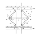
図1に示すように、本実施形態による建物の仮設支持構造1では、上梁9uに接する柱8上部の両側面に鋼製の第一軸受部5u、5uが、また、下梁9dに接する柱8下部の両側面に鋼製の第二軸受部5d、5dがそれぞれ図示しないアンカーボルトによって取り付けられるとともに、第一軸受部5u、5uと第二軸受部5d、5dを連結する一対のリンク機構2、2が柱芯に対して対称に取り付けられている。
リンク機構2、2は、第一軸受部5u、5uと、第二軸受部5d、5dと、一端が第一軸受部5u、5uに回動自在に支持された鋼製の第一アーム2u、2uと、一端が第二軸受部5d、5dに回動自在に支持された鋼製の第二アーム2d、2dと、第一アーム2u、2uの他端と第二アーム2d、2dの他端とをそれぞれ回動自在に連結する鋼製の連結部3、3とから構成される。
連結部3、3同士は、連結部3、3に形成された貫通孔3a、3aと、柱8の中央部に形成された貫通孔7とを挿通するPC鋼棒4の両端をボルト4aで締結することにより連結されている。そのため、リンク機構2、2は、リンク機構2、2を含む鉛直面内の変形自由度を有しているが、PC鋼棒4によってその変形は拘束されている。なお、リンク機構2、2は、鉛直面外へは変形することはできない。
Hereinafter, embodiments of a temporary support structure for a building according to the present invention will be described with reference to the drawings.
1 to 3 are views showing a first embodiment of a temporary support structure for a building according to the present invention.
As shown in FIG. 1, in the temporary support structure 1 for a building according to the present embodiment, steel first bearing
The
The connecting
柱8に圧縮力が作用すると、リンク機構2、2は水平方向に変形しようとするが、PC鋼棒4によってその変形が拘束されているため、PC鋼棒4には引張力が、第一アーム2u、2uと第二アーム2d、2dには圧縮力がそれぞれ発生する。そのため、第一アーム2u、2uと第二アーム2d、2dは座屈に対する配慮が必要である。
When compressive force acts on the
次に、本実施形態による建物の仮設支持構造1を用いた既存建物の免震化工事の手順について説明する。
(1)柱8上部の両側面および柱8下部の両側面にアンカーボルト(図示省略)を打設する。
(2)第一軸受部5u、5uを柱8上部のアンカーボルトに固定するとともに、第二軸受部5d、5dを柱8下部のアンカーボルトに固定し、柱8の両側にリンク機構2、2を取り付ける。
(3)柱8の中央部に貫通孔7を形成する。
(4)連結部3、3に形成された貫通孔3a、3aと、柱8の中央部に形成された貫通孔7にPC鋼棒4を挿通し、PC鋼棒4の両端をボルト4aで締結することにより、PC鋼棒4にプレストレスを導入する。
(5)ダイヤモンドカッター等を用いて柱8を柱面10u、10dで切断し、柱の一部10を除去する(図2参照)。
(6)柱面10u、10dにアンカーボルト13、13を打設した後、積層ゴムなどの免震装置11をアンカーボルト13、13に固定し、免震装置11と柱面10u、10dとの間隙に無収縮モルタル12を注入する(図3参照)。
(7)リンク機構2、2を撤去するとともに、貫通孔7内にモルタル等を充填する。
Next, the procedure of seismic isolation work for an existing building using the temporary building support structure 1 according to this embodiment will be described.
(1) Anchor bolts (not shown) are placed on both side surfaces of the upper part of the
(2) The first bearing
(3) The through hole 7 is formed at the center of the
(4) The
(5) The
(6) After the
(7) The
本実施形態による建物の仮設支持構造1では、リンク機構2、2を柱8の両側に取り付け、対向するリンク機構2、2同士をPC鋼棒4により連結するだけでよいため、柱8や上梁9u、下梁9dの補強を必要とせずに上部建物荷重を支持することができる。また、リンク機構2、2の取り付けおよび取り外しが簡単であるうえ、階高が異なる建物にも転用することができる。
In the temporary support structure 1 for a building according to the present embodiment, the
図4は、本発明に係る建物の仮設支持構造の第二の実施形態を示す図である。
図4に示すように、本実施形態による建物の仮設支持構造11では、第一軸受部15u、15uを両端に有する鋼製の第一梁材16u、16uが柱8上部の前後面に、また、第二軸受部15d、15dを両端に有する鋼製の第二梁材16d、16dが柱8下部の前後面にそれぞれ図示しないアンカーボルトによって取り付けられるとともに、第一軸受部15u、15uと第二軸受部15d、15dを連結する一対のリンク機構2、2が柱8の前後面にそれぞれ並設して取り付けられている。
柱8の前面の連結部3、3同士および柱8の後面の連結部3、3同士は、連結部3、3に形成された貫通孔3a、3aを挿通するPC鋼棒4の両端をボルト4aで締結することにより連結されている。
FIG. 4 is a view showing a second embodiment of a temporary support structure for a building according to the present invention.
As shown in FIG. 4, in the
The connecting
本実施形態による建物の仮設支持構造11では、一対のリンク機構2、2を柱8の前後面にそれぞれ並設して取り付けることにより、柱8に貫通孔7に形成する必要がなくなるため、工期が短縮される。
In the
以上、本発明に係る建物の仮設支持構造の実施形態について説明したが、本発明は上記の実施形態に限定されるものではなく、その趣旨を逸脱しない範囲で適宜変更可能である。例えば、上記の実施形態では、一対のリンク機構に対して1本のPC鋼棒を使用しているが、支持すべき上部建物荷重の大きさによっては、一対のリンク機構に対して複数本のPC鋼棒を使用すべきことは言うまでもない。 As mentioned above, although embodiment of the temporary support structure of the building which concerns on this invention was described, this invention is not limited to said embodiment, In the range which does not deviate from the meaning, it can change suitably. For example, in the above embodiment, one PC steel bar is used for a pair of link mechanisms, but depending on the magnitude of the upper building load to be supported, It goes without saying that PC steel bars should be used.
1、11 建物の仮設支持構造
2 リンク機構
2u 第一アーム
2d 第二アーム
3 連結部
4 PC鋼棒
5u、15u 第一軸受部
5d、15d 第二軸受部
7 貫通孔
8 柱
9u 上梁
9d 下梁
16u 第一梁材
16d 第二梁材
DESCRIPTION OF
Claims (3)
前記柱の上部に一端を回動自在に支持された第一アームの他端と、同柱の下部に一端を回動自在に支持された第二アームの他端とが回動自在に連結されたリンク機構が、前記柱を両側から挟むように取り付けられるとともに、前記対向するリンク機構同士が締付治具により連結されていることを特徴とする建物の仮設支持構造。 When a part of a pillar of an existing building is excised and a seismic isolation device is installed at the excision location, a temporary support structure for the building to support the building load above the excise location,
The other end of the first arm whose one end is rotatably supported on the upper part of the column and the other end of the second arm whose one end is rotatably supported on the lower part of the column are rotatably connected. A temporary support structure for a building, wherein the link mechanism is attached so as to sandwich the column from both sides, and the opposing link mechanisms are connected by a fastening jig.
Priority Applications (1)
| Application Number | Priority Date | Filing Date | Title |
|---|---|---|---|
| JP2003407445A JP4131470B2 (en) | 2003-12-05 | 2003-12-05 | Temporary support structure of building |
Applications Claiming Priority (1)
| Application Number | Priority Date | Filing Date | Title |
|---|---|---|---|
| JP2003407445A JP4131470B2 (en) | 2003-12-05 | 2003-12-05 | Temporary support structure of building |
Publications (2)
| Publication Number | Publication Date |
|---|---|
| JP2005163485A JP2005163485A (en) | 2005-06-23 |
| JP4131470B2 true JP4131470B2 (en) | 2008-08-13 |
Family
ID=34729494
Family Applications (1)
| Application Number | Title | Priority Date | Filing Date |
|---|---|---|---|
| JP2003407445A Expired - Fee Related JP4131470B2 (en) | 2003-12-05 | 2003-12-05 | Temporary support structure of building |
Country Status (1)
| Country | Link |
|---|---|
| JP (1) | JP4131470B2 (en) |
Families Citing this family (2)
| Publication number | Priority date | Publication date | Assignee | Title |
|---|---|---|---|---|
| CN106840731B (en) * | 2017-03-23 | 2023-03-14 | 福州大学 | Test piece freedom degree restraint device and construction method thereof |
| CN110778141A (en) * | 2019-11-13 | 2020-02-11 | 江苏工程职业技术学院 | Building reinforcing construction device |
-
2003
- 2003-12-05 JP JP2003407445A patent/JP4131470B2/en not_active Expired - Fee Related
Also Published As
| Publication number | Publication date |
|---|---|
| JP2005163485A (en) | 2005-06-23 |
Similar Documents
| Publication | Publication Date | Title |
|---|---|---|
| JP4261607B2 (en) | Moment resistant structure, support member, and construction method | |
| JP2004116081A (en) | Reinforcing construction of existing structure and reinforcing method | |
| JP4559996B2 (en) | Building reinforcement structure and method using iron-based shape memory alloy. | |
| JP4131470B2 (en) | Temporary support structure of building | |
| JP4203441B2 (en) | Tower crane support device and construction method thereof | |
| KR100930800B1 (en) | Construction method of ramen structure in which premoment is introduced | |
| JP6068510B2 (en) | Deck plate support and slab construction method using it | |
| JP4704851B2 (en) | Crane base isolation structure | |
| JP4635700B2 (en) | Building seismic control structure | |
| JP4654075B2 (en) | Tower crane foundation receiving beam structure | |
| JP3646575B2 (en) | Temporary support method and temporary support device | |
| JP4562631B2 (en) | Repair structure of hinge part in concrete structure | |
| KR20110108708A (en) | Reinforced concrete frame structure having high flexibility in beam-column joint | |
| JP3918705B2 (en) | Seismic isolation method for existing buildings | |
| JPH11210079A (en) | Earthquake-resistant reinforcing structure for leg portion of steel column of building and earthquake-resistant reinforcing method for leg portion of steel column of building | |
| JP7222825B2 (en) | Wooden building structural frame and joint members | |
| JP2019094630A (en) | Column capital displacement restraining structure of building | |
| KR102635664B1 (en) | Combined Structure of Long-term Steel Frame for Column Free Space | |
| CN212428175U (en) | Reinforcement structure of recoverable building engineering frame roof beam | |
| JP2019019656A (en) | Roof earthquake-resistant structure | |
| JP3176929U (en) | Structure support structure | |
| JP2019065532A (en) | Axial force resistant member | |
| JP5266074B2 (en) | Bending fracture type shear wall and building using the same | |
| JP3222807B2 (en) | Load-bearing wall panel | |
| JP3718451B2 (en) | Unit building |
Legal Events
| Date | Code | Title | Description |
|---|---|---|---|
| A621 | Written request for application examination |
Free format text: JAPANESE INTERMEDIATE CODE: A621 Effective date: 20060921 |
|
| A977 | Report on retrieval |
Free format text: JAPANESE INTERMEDIATE CODE: A971007 Effective date: 20080425 |
|
| TRDD | Decision of grant or rejection written | ||
| A01 | Written decision to grant a patent or to grant a registration (utility model) |
Free format text: JAPANESE INTERMEDIATE CODE: A01 Effective date: 20080507 |
|
| A01 | Written decision to grant a patent or to grant a registration (utility model) |
Free format text: JAPANESE INTERMEDIATE CODE: A01 |
|
| A61 | First payment of annual fees (during grant procedure) |
Free format text: JAPANESE INTERMEDIATE CODE: A61 Effective date: 20080520 |
|
| FPAY | Renewal fee payment (event date is renewal date of database) |
Free format text: PAYMENT UNTIL: 20110606 Year of fee payment: 3 |
|
| R150 | Certificate of patent or registration of utility model |
Free format text: JAPANESE INTERMEDIATE CODE: R150 |
|
| FPAY | Renewal fee payment (event date is renewal date of database) |
Free format text: PAYMENT UNTIL: 20110606 Year of fee payment: 3 |
|
| FPAY | Renewal fee payment (event date is renewal date of database) |
Free format text: PAYMENT UNTIL: 20120606 Year of fee payment: 4 |
|
| FPAY | Renewal fee payment (event date is renewal date of database) |
Free format text: PAYMENT UNTIL: 20120606 Year of fee payment: 4 |
|
| FPAY | Renewal fee payment (event date is renewal date of database) |
Free format text: PAYMENT UNTIL: 20130606 Year of fee payment: 5 |
|
| S531 | Written request for registration of change of domicile |
Free format text: JAPANESE INTERMEDIATE CODE: R313531 |
|
| R350 | Written notification of registration of transfer |
Free format text: JAPANESE INTERMEDIATE CODE: R350 |
|
| FPAY | Renewal fee payment (event date is renewal date of database) |
Free format text: PAYMENT UNTIL: 20140606 Year of fee payment: 6 |
|
| LAPS | Cancellation because of no payment of annual fees |