JP4131114B2 - Light emitting device, display device, and electronic device - Google Patents
Light emitting device, display device, and electronic device Download PDFInfo
- Publication number
- JP4131114B2 JP4131114B2 JP2002060135A JP2002060135A JP4131114B2 JP 4131114 B2 JP4131114 B2 JP 4131114B2 JP 2002060135 A JP2002060135 A JP 2002060135A JP 2002060135 A JP2002060135 A JP 2002060135A JP 4131114 B2 JP4131114 B2 JP 4131114B2
- Authority
- JP
- Japan
- Prior art keywords
- light emitting
- electrode
- layer
- transport layer
- dielectric multilayer
- Prior art date
- Legal status (The legal status is an assumption and is not a legal conclusion. Google has not performed a legal analysis and makes no representation as to the accuracy of the status listed.)
- Expired - Lifetime
Links
- 230000005525 hole transport Effects 0.000 claims description 56
- 239000000758 substrate Substances 0.000 claims description 28
- 238000005401 electroluminescence Methods 0.000 claims description 9
- 239000010408 film Substances 0.000 description 80
- 230000006870 function Effects 0.000 description 25
- 239000000463 material Substances 0.000 description 20
- 230000003287 optical effect Effects 0.000 description 8
- 239000012780 transparent material Substances 0.000 description 8
- 230000000694 effects Effects 0.000 description 6
- 238000000034 method Methods 0.000 description 6
- VYPSYNLAJGMNEJ-UHFFFAOYSA-N Silicium dioxide Chemical class O=[Si]=O VYPSYNLAJGMNEJ-UHFFFAOYSA-N 0.000 description 4
- 150000001875 compounds Chemical class 0.000 description 4
- 230000031700 light absorption Effects 0.000 description 4
- 229910052581 Si3N4 Inorganic materials 0.000 description 3
- 238000003384 imaging method Methods 0.000 description 3
- 238000002347 injection Methods 0.000 description 3
- 239000007924 injection Substances 0.000 description 3
- 238000010030 laminating Methods 0.000 description 3
- 229910052751 metal Inorganic materials 0.000 description 3
- 239000002184 metal Substances 0.000 description 3
- 230000004048 modification Effects 0.000 description 3
- 238000012986 modification Methods 0.000 description 3
- 150000002894 organic compounds Chemical class 0.000 description 3
- -1 polyphenylene Polymers 0.000 description 3
- HQVNEWCFYHHQES-UHFFFAOYSA-N silicon nitride Chemical compound N12[Si]34N5[Si]62N3[Si]51N64 HQVNEWCFYHHQES-UHFFFAOYSA-N 0.000 description 3
- 229910052814 silicon oxide Inorganic materials 0.000 description 3
- GWEVSGVZZGPLCZ-UHFFFAOYSA-N Titan oxide Chemical compound O=[Ti]=O GWEVSGVZZGPLCZ-UHFFFAOYSA-N 0.000 description 2
- HCHKCACWOHOZIP-UHFFFAOYSA-N Zinc Chemical compound [Zn] HCHKCACWOHOZIP-UHFFFAOYSA-N 0.000 description 2
- 239000000956 alloy Substances 0.000 description 2
- 229910045601 alloy Inorganic materials 0.000 description 2
- 238000004770 highest occupied molecular orbital Methods 0.000 description 2
- 150000002484 inorganic compounds Chemical class 0.000 description 2
- 229910010272 inorganic material Inorganic materials 0.000 description 2
- 238000004768 lowest unoccupied molecular orbital Methods 0.000 description 2
- 230000007246 mechanism Effects 0.000 description 2
- 239000000203 mixture Substances 0.000 description 2
- 230000002093 peripheral effect Effects 0.000 description 2
- 239000000126 substance Substances 0.000 description 2
- XOLBLPGZBRYERU-UHFFFAOYSA-N tin dioxide Chemical compound O=[Sn]=O XOLBLPGZBRYERU-UHFFFAOYSA-N 0.000 description 2
- 229910052725 zinc Inorganic materials 0.000 description 2
- 239000011701 zinc Substances 0.000 description 2
- RETDKIXQRINZEF-UHFFFAOYSA-N 1,3-benzoxazole;zinc Chemical class [Zn].C1=CC=C2OC=NC2=C1 RETDKIXQRINZEF-UHFFFAOYSA-N 0.000 description 1
- 229920000265 Polyparaphenylene Polymers 0.000 description 1
- NRCMAYZCPIVABH-UHFFFAOYSA-N Quinacridone Chemical class N1C2=CC=CC=C2C(=O)C2=C1C=C1C(=O)C3=CC=CC=C3NC1=C2 NRCMAYZCPIVABH-UHFFFAOYSA-N 0.000 description 1
- 229910006404 SnO 2 Inorganic materials 0.000 description 1
- 150000004984 aromatic diamines Chemical class 0.000 description 1
- 125000000732 arylene group Chemical group 0.000 description 1
- 230000004888 barrier function Effects 0.000 description 1
- 230000015572 biosynthetic process Effects 0.000 description 1
- 230000001413 cellular effect Effects 0.000 description 1
- 230000008859 change Effects 0.000 description 1
- 239000012141 concentrate Substances 0.000 description 1
- 239000003989 dielectric material Substances 0.000 description 1
- 239000000539 dimer Substances 0.000 description 1
- 238000000295 emission spectrum Methods 0.000 description 1
- PCHJSUWPFVWCPO-UHFFFAOYSA-N gold Chemical compound [Au] PCHJSUWPFVWCPO-UHFFFAOYSA-N 0.000 description 1
- 239000010931 gold Substances 0.000 description 1
- 229910052737 gold Inorganic materials 0.000 description 1
- 239000004973 liquid crystal related substance Substances 0.000 description 1
- 229910001635 magnesium fluoride Inorganic materials 0.000 description 1
- 239000012788 optical film Substances 0.000 description 1
- 230000001902 propagating effect Effects 0.000 description 1
- YYMBJDOZVAITBP-UHFFFAOYSA-N rubrene Chemical class C1=CC=CC=C1C(C1=C(C=2C=CC=CC=2)C2=CC=CC=C2C(C=2C=CC=CC=2)=C11)=C(C=CC=C2)C2=C1C1=CC=CC=C1 YYMBJDOZVAITBP-UHFFFAOYSA-N 0.000 description 1
- 238000004528 spin coating Methods 0.000 description 1
- 239000010409 thin film Substances 0.000 description 1
- 150000003852 triazoles Chemical class 0.000 description 1
- 125000006617 triphenylamine group Chemical group 0.000 description 1
- 238000007740 vapor deposition Methods 0.000 description 1
Images


Classifications
-
- H—ELECTRICITY
- H10—SEMICONDUCTOR DEVICES; ELECTRIC SOLID-STATE DEVICES NOT OTHERWISE PROVIDED FOR
- H10K—ORGANIC ELECTRIC SOLID-STATE DEVICES
- H10K50/00—Organic light-emitting devices
- H10K50/30—Organic light-emitting transistors
-
- H—ELECTRICITY
- H10—SEMICONDUCTOR DEVICES; ELECTRIC SOLID-STATE DEVICES NOT OTHERWISE PROVIDED FOR
- H10K—ORGANIC ELECTRIC SOLID-STATE DEVICES
- H10K50/00—Organic light-emitting devices
- H10K50/80—Constructional details
- H10K50/85—Arrangements for extracting light from the devices
- H10K50/852—Arrangements for extracting light from the devices comprising a resonant cavity structure, e.g. Bragg reflector pair
-
- H—ELECTRICITY
- H10—SEMICONDUCTOR DEVICES; ELECTRIC SOLID-STATE DEVICES NOT OTHERWISE PROVIDED FOR
- H10K—ORGANIC ELECTRIC SOLID-STATE DEVICES
- H10K50/00—Organic light-emitting devices
- H10K50/80—Constructional details
- H10K50/805—Electrodes
-
- H—ELECTRICITY
- H10—SEMICONDUCTOR DEVICES; ELECTRIC SOLID-STATE DEVICES NOT OTHERWISE PROVIDED FOR
- H10K—ORGANIC ELECTRIC SOLID-STATE DEVICES
- H10K59/00—Integrated devices, or assemblies of multiple devices, comprising at least one organic light-emitting element covered by group H10K50/00
- H10K59/80—Constructional details
- H10K59/805—Electrodes
-
- H—ELECTRICITY
- H10—SEMICONDUCTOR DEVICES; ELECTRIC SOLID-STATE DEVICES NOT OTHERWISE PROVIDED FOR
- H10K—ORGANIC ELECTRIC SOLID-STATE DEVICES
- H10K59/00—Integrated devices, or assemblies of multiple devices, comprising at least one organic light-emitting element covered by group H10K50/00
- H10K59/80—Constructional details
- H10K59/875—Arrangements for extracting light from the devices
- H10K59/876—Arrangements for extracting light from the devices comprising a resonant cavity structure, e.g. Bragg reflector pair
-
- H—ELECTRICITY
- H10—SEMICONDUCTOR DEVICES; ELECTRIC SOLID-STATE DEVICES NOT OTHERWISE PROVIDED FOR
- H10K—ORGANIC ELECTRIC SOLID-STATE DEVICES
- H10K2102/00—Constructional details relating to the organic devices covered by this subclass
- H10K2102/301—Details of OLEDs
- H10K2102/302—Details of OLEDs of OLED structures
- H10K2102/3023—Direction of light emission
- H10K2102/3026—Top emission
Description
【0001】
【発明の属する技術分野】
本発明は、EL(エレクトロルミネッセンス)を用いた面発光型の発光装置、ならびに該発光装置を用いた表示装置および電子機器に関する。
【0002】
【背景技術および発明が解決しようとする課題】
EL(エレクトロルミネッセンス)を用いたEL発光素子においては、発光が等方的に行われて指向性が悪いため、特定の方向についてみると、光の強度が弱く、出射光を高い効率で利用することができないという難点を有する。
【0003】
本発明の目的は、基板に交差する方向に出射される光の波長選択性に優れ、光を効率よく利用することができる発光装置を提供することにある。
【0004】
また、本発明の目的は、前記発光装置を用いた表示装置および電子機器を提供することにある。
【0005】
【課題を解決するための手段】
本発明にかかる有機発光装置は、
基板と、
第1膜と、
有機発光層と、
第1電極と、
第2電極と、を含み、
前記基板と前記第2電極との間に前記第1膜が位置し、
前記第1膜と前記第2電極との間に前記有機発光層が位置し、
前記第1膜と前記有機発光層との間に前記第1電極が位置し、
前記第2電極が導電性透明材料からなる。
本発明にかかる有機発光装置において、
さらに第2膜を有し、
前記第2電極が前記有機発光層と前記第2膜の間に位置するものであることができる。
本発明にかかる有機発光装置は、
基板と、
第1膜と、
第2膜と、
有機発光層と、
第1電極と、を含み、
前記基板と前記第2膜との間に前記第1膜が位置し、
前記第1膜と前記第2膜との間に前記有機発光層が位置し、
前記第1膜と前記有機発光層との間に前記第1電極が位置し、
前記第2電極が導電性透明材料からなる。
本発明にかかる有機発光装置において、
前記有機発光層で発生した光が前記第1膜で反射され前記第2膜から出射されるよう構成されていることができる。
本発明にかかる有機発光装置において、
前記第1膜の反射率より前記第2膜の反射率のほうが小さく構成されていることができる。
本発明にかかる有機発光装置において、
前記第2膜が前記有機発光層で発生した光を選択的に反射するよう構成されていることができる。
本発明にかかる有機発光装置において、
前記第1膜で反射される光の波長帯域が前記有機発光層で発生する光の波長帯域とほぼ一致することができる。
本発明にかかる有機発光装置において、
前記第1膜と前記有機発光層との間に電子輸送層が位置することができる。
本発明にかかる有機発光装置において、
前記第2電極と前記有機発光層との間にホール輸送層が位置することができる。
本発明にかかる有機発光装置において、
前記第2膜の第1の部分が前記第1電極と重なり、前記第2膜の第2の部分が前記第1電極と重ならないことができる。
本発明にかかる有機発光装置において、
前記第1膜と前記有機発光層との間に前記第1電極が位置しない部分を有することができる。
本発明にかかる有機発光装置において、
前記第1膜が第1電極層を含むことができる。
本発明にかかる有機発光装置において、
前記第1膜が屈折率の互いに異なる材料が積層された構造であることができる。
本発明にかかる有機発光装置において、
前記第1膜が酸化シリコン層と窒化シリコン層の積層構造であることができる。
本発明にかかる有機発光装置において、
前記導電性透明材料がITOを含むことができる。
本発明にかかる有機発光装置において、
前記導電性透明材料がSnO 2 を含むことができる。
本発明にかかる有機発光装置において、
前記導電性透明材料がZnOを含むことができる。
本発明にかかる有機発光装置において、
前記導電性透明材料がCuIを含むことができる。
本発明にかかる有機発光装置は、
第1膜と、
第2膜と、
前記第1膜と前記第2膜との間に位置するホール輸送層と、
前記第1膜と前記第2膜との間に位置する有機発光層と、
前記第1膜と前記第2膜との間に位置する電子輸送層と、
前記電子輸送層に接する第1電極と、
前記ホール輸送層に接する第2電極と、を含み、
前記ホール輸送層と前記電子輸送層との間に前記有機発光層が位置し、前記有機発光層の一方の面が前記第1膜に接し、前記有機発光層の他方の面が前記第2膜に接するよう構成されている。
本発明にかかる表示装置は、
前記有機発光装置を含むことができる。
本発明にかかる電子機器は、
前記有機発光装置を含むことができる。
本発明にかかる発光装置は、基板と、該基板上に形成された発光素子部とを含み、前記基板と交差する方向に光が出射される発光装置であって、
前記発光素子部は、
エレクトロルミネッセンスによって光を発生する発光層と、
前記発光層に電荷を注入するための電極と、
前記発光層を挟む状態で配置される第1および第2誘電体多層膜と、を含み、
前記電極は、前記発光層における発光領域の少なくとも一部に対し、光の出射方向からみて重ならないように配置される。
【0006】
この発光装置によれば、前記第1および第2誘電体多層膜によって波長選択性が高められる。その結果、前記発光層においてエレクトロルミネッセンスによって発生した光は、前記第1および第2誘電体多層膜の高反射帯域に対応する狭い波長帯域において高効率で光が出射される。さらに、この発光装置によれば、前記電極は、前記発光層の発光領域に対し、光の出射方向からみて重ならないように配置されることから、該電極による光の吸収や散乱を低減できる。その結果、前記発光層で発生する光を高い効率で利用することができる。
【0007】
ここで、「前記電極は、前記発光層の発光領域に対し、光の出射方向からみて重ならないように配置」するとは、前記発光層の発光領域で発生した光が前記第1および第2誘電体多層膜の間を伝播する際に、前記電極によってできるだけ遮られないように配置されることを意味する。より具体的には、前記誘電体多層膜の堆積される方向(前記基板の表面と交差する方向)において、前記発光領域の全体もしくは一部と重なる位置に前記電極は形成されない。
【0008】
本発明においては、以下に示す各種態様を取りうる。
【0009】
(A)前記電極としては、電子を前記発光層に注入するための1対の電極層からなる第1電極、およびホールを前記発光層に注入するための1対の電極層からなる第2電極を有することができる。この構成によれば、第1および第2電極はそれぞれ1対の電極層を有することから、一方の電極層をいわゆるソースとして、他方の電極層をいわゆるドレインとして機能させることができる。ここで、「ソース」とは、たとえば電子を供給する領域をいい、「ドレイン」とは、たとえばホールを供給する領域をいう。したがって、ドレインがソースに対して正電位になるように電圧を印加することによって、ホール輸送層にドレインからソースにホールを誘導することができる。また、ソースがドレインに対して負電位になるように電圧を印加することによって、電子輸送層にソースからドレインに電子を誘導することができる。
【0010】
(B)さらに、前記第1電極は、電子輸送層と接続され、前記第2電極は、ホール輸送層に接続されることができる。この構成によれば、前記第1電極によって電子輸送層に所定の電圧を印加し、前記第2電極によってホール輸送層に所定の電圧を印加することができる。したがって、電子輸送層とホール輸送層とにそれぞれ独立に電圧を印加できるので、大量の電子およびホールを輸送することができる。
【0011】
(C)さらに、前記第1電極に対して絶縁層を介在させて配置される第3電極を有し、前記第2電極に対して絶縁層を介在させて配置される第4電極を有することができる。この第3および第4電極は、第1電極および第2電極に対してゲートとしての機能を有することができる。たとえば、第3および第4電極に所定の電圧を印加することにより、電子輸送層とホール輸送層とに電位差を与えることができ、その結果、電子輸送層内の電子とホール輸送層内のホールとを大量に発光層に移動させることができる。したがって、発光層内において発光に寄与する電子とホールの数を増加させることでき、発光効率を高めることができる。
【0012】
(D)第1および第2電極は、たとえば以下の配置をとることができる。
【0013】
第1に、前記基板と交差する方向すなわち光の出射方向に対して、前記第1電極は、前記発光層の一方の側に配置され、前記第2電極は、前記発光層の他方の側に配置される。
【0014】
第2に、前記基板の面方向すなわち基板の表面と平行な方向において、前記第1電極は、前記発光層の一方の側に配置され、前記第2電極は、前記発光層の他方の側に配置される。
【0015】
(E)前記誘電体多層膜で反射される光の波長帯域は、前記発光層で発生する光の波長帯域に含まれる。この構成によって、第1および第2誘電体多層膜によっていわゆる光共振器を構成することができる。また、光は、1対の誘電体多層膜のうち、反射率が低い方から出射される。
【0016】
また、本発明の発光装置は、表示装置に適用することができる。さらに、この表示装置は各種の電子機器に適用することができる。あるいは、本発明の発光装置は各種の電子機器に適用することができる。かかる表示装置および電子機器の具体例については後述する。
【0017】
次に、本発明にかかる発光装置の各部分に用いることができる材料の一部を例示する。これらの材料は、公知の材料の一部を示したにすぎず、例示したもの以外の材料を選択できることはもちろんである。
【0018】
(発光層)
発光層の材料は、所定の波長の光を得るために公知の化合物から選択される。発光層の材料としては、有機化合物および無機化合物のいずれでもよいが、種類の豊富さや成膜性の点から有機化合物であることが望ましい。
【0019】
このような有機化合物としては、例えば、特開平10−153967号公報に開示された、アロマティックジアミン誘導体(TPD)、オキシジアゾール誘導体(PBD)、オキシジアゾールダイマー(OXD−8)、ジスチルアリーレン誘導体(DSA)、ベリリウム−ベンゾキノリノール錯体(Bebq)、トリフェニルアミン誘導体(MTDATA)、ルブレン、キナクリドン、トリアゾール誘導体、ポリフェニレン、ポリアルキルフルオレン、ポリアルキルチオフェン、アゾメチン亜鉛錯体、ポリフィリン亜鉛錯体、ベンゾオキサゾール亜鉛錯体、フェナントロリンユウロピウム錯体などが使用できる。
【0020】
より具体的には、有機発光層の材料としては、特開昭63−70257号公報、同63−175860号公報、特開平2−135361号公報、同2−135359号公報、同3−152184号公報、さらに、同8−248276号公報および同10−153967号公報に記載されているものなど、公知のものが使用できる。これらの化合物は単独で用いてもよく、2種類以上を混合して用いてもよい。
【0021】
無機化合物としては、ZnS:Mn(赤色領域)、ZnS:TbOF(緑色領域)、SrS:Cu、SrS:Ag、SrS:Ce(青色領域)などが例示される。
【0022】
(誘電体多層膜)
発光素子部において、誘電体多層膜は、屈折率が互いに異なる材料が交互に積層された構造を有する。このような積層構造としては、例えば酸化シリコン層(SiO2)と窒化シリコン層(SiNx)とが交互に積層された層構造が挙げられる。その他、例えば、TiO2、Ta2O5、MgF2、およびZnSから選択される2層を交互に積層して誘電体多層膜を形成することができる。
【0023】
(電極層)
陰極、すなわち、発光層に電子を注入するための電極としては、仕事関数の小さい(例えば4eV以下)電子注入性金属、合金電気伝導性化合物およびこれらの混合物を用いることができる。このような電極物質としては、例えば特開平8−248276号公報に開示されたものを用いることができる。
【0024】
陽極、すなわち、発光層にホールを注入するための電極としては、仕事関数の大きい(例えば4eV以上)金属、合金、電気伝導性化合物またはこれらの混合物を用いることができる。陽極として光学的に透明な材料を用いる場合には、CuI,ITO,SnO2,ZnOなどの導電性透明材料を用いることができ、透明性を必要としない場合には金などの金属を用いることができる。
【0025】
また、電子輸送層に接続される第1電極としては、以下の関係が成立することが望ましい。
【0026】
[一方の電極層(ソース)の仕事関数>電子輸送層の最低空順位(LUMO:Lowest Unoccupied Molecular Orbital)<他方の電極層(ドレイン)の仕事関数]
さらに、ホール輸送層に接続される第2電極としては、以下の関係が成立することが望ましい。
【0027】
[一方の電極層(ソース)の仕事関数<ホール輸送層の最高被占順位(HOMO:Highest Occupied Molecular Orbital)<他方の電極層(ドレイン)の仕事関数]
前記第3および第4電極は、第1および第2電極のための前述したゲートとして機能を有する導電層であればよく、特に限定されない。ただし、第3および第4電極が誘電体多層膜を構成する場合には、その特性を満たす材質であることが要求される。
【0028】
(ホール輸送層)
必要に応じて設けられるホール輸送層の材料としては、公知の光伝導材料のホール注入材料として用いられているもの、あるいは有機発光装置のホール注入層に使用されている公知のものの中から選択して用いることができる。ホール輸送層の材料は、ホールの注入あるいは電子の障壁性のいずれかの機能を有するものであり、有機物あるいは無機物のいずれでもよい。その具体例としては、例えば、特開平8−248276号公報に開示されているものを例示することができる。
【0029】
(電子輸送層)
必要に応じて設けられる電子輸送層の材料としては、陰極より注入された電子を有機発光層に伝達する機能を有していればよく、その材料は公知の物質から選択することができる。その具体例としては、例えば、特開平8−248276号公報に開示されたものを例示することができる。
【0030】
また、発光装置の各層は、公知の方法で形成することができる。たとえば、発光装置の各層は、その材質によって好適な成膜方法が選択され、具体的には、蒸着法、スピンコート法、LB法、インクジェット法などを例示できる。
【0031】
【発明の実施の形態】
[第1の実施の形態]
(デバイスの構造)
図1は、本発明の第1の実施の形態にかかる発光装置100を模式的に示す断面図である。
【0032】
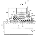
発光装置100は、基板10上に発光素子部を有する。発光素子部は、第1誘電体多層膜20a,電子輸送層22,発光層24,ホール輸送層26および第2誘電体多層膜20bが順次積層されて形成されている。
【0033】
第1誘電体多層膜20a上には、電子輸送層22に電子を注入するための、1対の電極層32および34からなる第1電極30が配置されている。本実施の形態では、一方の電極層32はソース(S1)として機能し、他方の電極層34はドレイン(D1)として機能する。そして、一方の電極層32と他方の電極層34とは、所定の間隔をおいて配置されている。したがって、電極層32および34に所定の電圧を印加することで、電子輸送層22に電子が注入される。
【0034】
また、ホール輸送層26上には、ホール輸送層26にホールを注入するための、1対の電極層42および44からなる第2電極40が配置されている。本実施の形態では、一方の電極層42はソース(S2)として機能し、他方の電極層44はドレイン(D2)として機能する。そして、一方の電極層42と他方の電極層44とは、所定の間隔をおいて配置されている。したがって、電極層42および44に所定の電圧を印加することで、ホール輸送層26にホールが注入される。
【0035】
このように、第1および第2電極30,40を構成する電極層32,34および42,44は、発光層24の発光領域24aに対し、図中、矢印で示す光の出射方向からみて重ならない位置に配置されている。
【0036】
発光層24は、エレクトロルミネッセンスによって光を発生する材料から形成されている。発光層24,電子輸送層22およびホール輸送層26には、前述したものを用いることができる。
【0037】
第1および第2誘電体多層膜20a,20bは、基板10と直交する方向において、電子輸送層22,発光層24およびホール輸送層26を挟む状態で配置されている。
【0038】
第1および第2誘電体多層膜20a,20bは、例えば、酸化シリコン層と窒化シリコン層の積層のように、屈折率が互いに異なる材料が交互に積層された構造からなる。この交互に積層される各層は、厚さが約λ/4n(λは発光層24で発生する光の波長帯域内にある所定波長)となるように形成される。
【0039】
第1および第2誘電体多層膜20a,20bは、所定の波長帯域の光を反射する。第1および第2誘電体多層膜20a,20bによって反射される光の波長帯域は、発光層24で発生する光の波長帯域に基づいて規定される。すなわち、第1および第2誘電体多層膜20a,20bは、これらによって反射される光の波長帯域が発光層24で発生する光の波長帯域に含まれるように形成される。この構成によれば、発光層24で発生した光は、第1および第2誘電体多層膜20a,20bの高反射率帯域の波長の光のみが選択的に反射される。その結果、出射光のスペクトル幅が小さく高い発光効率で光を出射できる。発光効率をさらに高めるためには、第1および第2誘電体多層膜20a,20bによって反射される光の波長帯域が、発光層24で発生する光の波長帯域とほぼ一致することがより好ましい。
【0040】
この例の場合、第2誘電体多層膜20bの反射率は第1誘電体多層膜20aの反射率より小さく設定されている。そのため、光は第2誘電体多層膜20b側から出射される。1対の誘電体多層膜の反射率は、光を出射させたい方向によって適宜設定される。
【0041】
さらに、第1電極30(電極層32,34)に対して、第1誘電体多層膜20aを構成する誘電体層21を介して第3電極50が形成されている。また、同様に、第2電極40(電極層42,44)に対して、第2誘電体多層膜20bを構成する誘電体層21を介して第4電極52が形成されている。
【0042】
これらの第3および第4電極50,52は、いずれも、誘電体多層膜20a,20bの層を構成する。すなわち、第3および第4電極50,52は、誘電体多層膜20a,20bに必要な屈折率と光学的膜厚を有し、さらに、導電性も有する。これらの電極50,52の材料は、これらの要件を満たせば特に限定されず、たとえばITOなどを用いることができる。
【0043】
(デバイスの動作および作用効果)
本実施の形態にかかる発光装置100においては、以下のメカニズムで光の出射が行われる。
【0044】
第1電極30の電極層(ソース)32および電極層(ドレイン)34に所定の電圧を印加することで、電子輸送層22に電子を大量に注入できる。また、第2電極40の電極層(ソース)42および電極層(ドレイン)44に所定の電圧を印加することで、ホール輸送層26にホールを大量に注入できる。すなわち、ドレインがソースに対して正電位になるように電圧を印加することによって、ホール輸送層26にドレインからソースにホールを大量に誘導することができる。また、ソースがドレインに対して負電位になるように電圧を印加することによって、電子輸送層22にソースからドレインに電子を誘導することができる。
【0045】
さらに、第3電極50および第4電極52に所定の電圧を印加することにより、電子輸送層22とホール輸送層26とに電位差を与えることができ、その結果、電子輸送層22内の電子とホール輸送層26内のホールとを大量に発光層24に移動させることができる。したがって、発光層24内において発光に寄与する電子とホールの数を増加させることでき、発光効率を高めることができる。
【0046】
本実施の形態では、第1電極30は電子輸送層22と接続され、第2電極40は、ホール輸送層26に接続される。したがって、電子輸送層22とホール輸送層26とに、それぞれ独立に電圧を印加できるので、この点からも大量の電子およびホールを輸送することができる。
【0047】
このようにして、電子輸送層22に注入された電子と、ホール輸送層26に注入されたホールとが、発光層24内で結合されることにより励起子が生成され、この励起子が失活する際に光が生じる。
【0048】
発光層24で発生した光は、1対の誘電体多層膜20a,20bによって構成される光共振器によって波長選択性が高められる。その結果、発光層24においてエレクトロルミネッセンスによって発生した光は、光共振器の波長に対応する狭い波長帯域において高効率で出射される。
【0049】
さらに、この発光装置100によれば、第1および第2電極30,40は、発光層24の発光領域24aに対し、光の出射方向からみて重ならないように配置されている。その結果、第1および第2電極30,40を構成する電極層32,34および電極層42,44による光の吸収や散乱を低減でき、発光層24で発生する光を高い効率で利用することができる。
【0050】
[第2の実施の形態]
(デバイスの構造)
図2は、本発明の第2の実施の形態にかかる発光装置200を模式的に示す断面図であり、図3は、図2のA−A線に沿った要部の平面構造を示すための断面図である。本実施の形態では、電子輸送層、発光層およびホール輸送層の配列が第1の実施の形態と異なる。図1に示す部材と実質的に同じ機能を有する部材には同一符号を付し、主要な相違点を主に説明する。
【0051】
発光装置200は、基板10上に発光素子部を有する。発光素子部は、第1誘電体多層膜20a,発光層24および第2誘電体多層膜20bが順次積層されて形成されている。そして、基板10の面方向に対して、発光層24の一方の側に電子輸送層22が、他方の側にホール輸送層26が配置されている。
【0052】
電子輸送層22の上下には、電子輸送層22に電子を注入するための、1対の電極層32および34(第1電極30)が配置されている。本実施の形態では、一方の電極層32はソース(S1)として機能し、他方の電極層34はドレイン(D1)として機能する。したがって、電極層32および34に所定の電圧を印加することで、電子輸送層22に電子が注入される。
【0053】
また、ホール輸送層26の上下には、ホール輸送層26にホールを注入するための、1対の電極層42および44(第2電極40)が配置されている。本実施の形態では、一方の電極層42はソース(S2)として機能し、他方の電極層44はドレイン(D2)として機能する。したがって、電極層42および44に所定の電圧を印加することで、ホール輸送層26にホールが注入される。
【0054】
このように、第1および第2電極30,40を構成する電極層32,34および42,44は、発光層24に対し、図中、矢印で示す光の出射方向からみて重ならない位置に配置されている。
【0055】
さらに、電子輸送層22の外側(発光層24の反対側)には、絶縁層54を介して第3電極50が形成されている。さらに、第3電極50は、絶縁層54を介して第1電極30を構成する電極層32,34と電気的に分離されている。同様に、ホール輸送層26の外側(発光層24の反対側)には、絶縁層54を介して第4電極52が形成されている。さらに、第4電極52は、絶縁層54を介して第2電極40を構成する電極層42,44と電気的に分離されている。
【0056】
第3電極50および第4電極52は、図3に示すように、それぞれ、電子輸送層22およびホール輸送層26内に進入する突出部50a,52aを有する。このような突出部50a,52aを有することで、発光層24の中央部のみに選択的に電圧を印加できるので、発光箇所を中央部に集中させることができる。したがって、第1電極30および第2電極40での光の吸収を小さくでき、発光効率をより向上させることができる。
【0057】
第1および第2誘電体多層膜20a,20bについては、第1の実施の形態と同様であるので、記載を省略する。
【0058】
(デバイスの動作および作用効果)
本実施の形態にかかる発光装置200においても、基本的に第1の実施の形態と同様な動作および作用効果を有するので、本実施の形態で第1の実施の形態と異なる動作および作用効果のみ記載する。
【0059】
すなわち、本実施の形態では、第1の実施の形態の作用効果に加えて、ゲートとして機能する第3電極50および第4電極52は、薄い絶縁層54を介して電子輸送層22およびホール輸送層26に接続されているため、低いゲート電圧で効果的な電子およびホールの輸送が可能となる。
【0060】
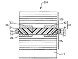
(変形例)
図4は、第2の実施の形態にかかる発光装置の変形例を示す断面図である。図2および図3で示す部材と実質的に同じ機能を有する部材には同一符号を付して、その詳細な説明を省略する。この例の発光装置210では、ホール輸送層が形成されていない他は、図2および図3に示す発光装置200と同様である。すなわち、第2電極40を構成する電極層42および44は、ホール輸送層を介さないで発光層24と直接接続するように配置されている。また、ホール輸送層の代わりに電子輸送層を設けないこともでき、あるいは、電子輸送層およびホール輸送層の両者を設けないこともできる。
【0061】
このことは、他の実施の形態についても同様である。すなわち、第1および後述する第3の実施の形態では、電子輸送層22およびホール輸送層26の少なくとも一方を有することができ、あるいは、いずれも有しないこともできる。
【0062】
[第3の実施の形態]
(デバイスの構造)
図5は、本発明の第3の実施の形態にかかる発光装置300を模式的に示す断面図である。本実施の形態では、第1電極および第2電極の構成が第1および第2の実施の形態と異なる。図1に示す部材と実質的に同じ機能を有する部材には同一符号を付し、主要な相違点を主に説明する。
【0063】
発光装置300は、基板10上に発光素子部を有する。発光素子部は、第1誘電体多層膜20a,電子輸送層22,発光層24,ホール輸送層26および第2誘電体多層膜20bが順次積層されて形成されている。
【0064】
第1誘電体多層膜20a上には、電子輸送層22と接続される陰極60が形成されている。また、ホール輸送層26上には、ホール輸送層26と接続される陽極62が形成されている。そして、陰極60と陽極62とは、発光層24の発光領域24aに対し、図中、矢印で示す光の出射方向からみて重ならない位置に配置されている。より具体的には、陰極60の端部60aと陽極62の端部62aとは、所定の間隔を置いて配置されている。
【0065】
第1および第2誘電体多層膜20a,20bについては、第1の実施の形態と同様であるので、記載を省略する。
【0066】
(デバイスの動作および作用効果)
本実施の形態にかかる発光装置300においては、以下のメカニズムで光の出射が行われる。すなわち、陰極60および陽極62に所定の電圧を印加することで、電子輸送層22に電子を注入でき、かつ、ホール輸送層22にホールを注入できる。このようにして、電子輸送層22に注入された電子と、ホール輸送層26に注入されたホールとが、発光層24内で結合されることにより励起子が生成され、この励起子が失活する際に光が生じる。
【0067】
発光層24で発生した光は、1対の誘電体多層膜20a,20bによって構成される光共振器によって波長選択性が高められる。その結果、発光層24においてエレクトロルミネッセンスによって発生した光は、光共振器の波長に対応する狭い波長帯域において高効率で出射される。
【0068】
さらに、この発光装置300によれば、陰極60および陽極62は、発光層24の発光領域24aに対し、光の出射方向からみて重ならないように配置されている。その結果、陰極60および陽極62による光の吸収や散乱を低減でき、発光層24で発生する光を高い効率で利用することができる。
【0069】
[第4の実施の形態]
(表示装置および電子機器)
本発明の発光装置、例えば各実施の形態の発光装置100,200,210,300は、表示装置に適用することができる。また、各発光装置を含む表示装置は、電子機器に適用することができる。図6〜図11はそれぞれ、各発光装置100,200,210,300を含む表示装置500が適用された電子機器の例を示す斜視図である。
【0070】
図6は、本実施の形態の電子機器の一例たる電子ブック1000の構成を示す斜視図である。電子ブック1000は、ブック形状のフレーム32と、このフレーム32に開閉可能なカバー33とを有する。フレーム32には、その表面に表示面を露出された状態で表示装置500が設けられ、さらに、操作部35が設けられている。フレーム32の内部には、コントローラ、カウンタ、およびメモリ(図示せず)が内蔵されている。本実施の形態では、表示装置500は、電子インクを薄膜素子に充填して形成した画素部と、この画素部と一体に備えられかつ集積化された周辺回路(図示せず)とを備える。この周辺回路は、デコーダ式のスキャンドライバおよびデータドライバを備える。
【0071】
図7は、本実施の形態の電子機器の一例たるパーソナルコンピュータ1100の構成を示す斜視図である。このパーソナルコンピュータ1100は、キーボード1102を備えた本体部1104と、上述した表示装置500を備えた表示ユニットから構成される。
【0072】
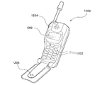
図8は、本実施の形態の電子機器の一例たる携帯電話1200の構成を示す斜視図である。図8において、携帯電話1200は、複数の操作ボタン1202のほか、受話口1204、送話口1206とともに、上述した表示装置500を備える。
【0073】
図9は、本実施の形態の電子機器の一例たるディジタルスチルカメラ1300の構成を示す斜視図である。図9においては、ディジタルスチルカメラ1300の構成とともに、ディジタルスチルカメラ1300と外部機器との接続についても簡易的に示す。
【0074】
通常のカメラは、被写体の光像によってフィルムを感光するのに対し、ディジタルスチルカメラ1300は、被写体の光像をCCDによる撮像素子により光電変換して撮像信号を生成する。ここで、ディジタルスチルカメラ1300の背面には、上述した表示装置500が設けられ、CCDによる撮像信号に基づいて表示を行なう構成を有する。すなわち、表示装置500は、被写体を表示するファインダとして機能する。また、ケース1302の観察側(図9においては裏面側)には、光学レンズやCCD等を含んだ受光ユニット1304が設けられている。ここで、撮影者が表示装置500に表示された被写体像を確認して、シャッタボタン1306を押下すると、その時点におけるCCDの撮像信号が回路基板1308のメモリに転送され格納される。また、このディジタルスチルカメラ1300においては、ケース1302の側面にビデオ信号出力端子1312と、データ通信用の入出力素子1314とが設けられている。そして、図9に示すように、ビデオ信号出力素子1312にはテレビモニタ1430が、データ通信用の入出力素子1314にはパーソナルコンピュータ1440が、それぞれ必要に応じて接続される。さらに、所定の操作によって、回路基板1308のメモリに格納された撮像信号が、テレビモニタ1430やパーソナルコンピュータ1440に出力される構成となっている。
【0075】
図10は、本実施の形態の電子機器の一例たる電子ペーパー1400の構成を示す斜視図である。図10において、電子ペーパー1400は、紙と同様の質感および柔軟性を有するリライタブルシートからなる本体1401と、上述した表示装置500とを備えた表示ユニットから構成される。
【0076】
図11は、本実施の形態の電子機器の一例たる電子ノート1402の構成を示す斜視図である。図11において、電子ノート1402は、図10に示す電子ペーパー1400が複数枚束ねられ、カバー1403に挟まれて構成されている。また、電子ノート1402は、カバー1403に表示データ入力手段を設けることにより、束ねられた状態で電子ペーパー1400の表示内容を変更することができる。
【0077】
なお、電子機器としては、図6に示す電子ブック1000、図7に示すパーソナルコンピュータ1100、図8に示す携帯電話1200、図9に示すディジタルスチルカメラ1300、図10に示す電子ペーパー1400、および図11に示す電子ノート1402のほか、液晶テレビや、ビューファインダ型またはモニタ直視型のビデオテープレコーダ、カーナビゲーション装置、ページャ、電子手帳、電卓、ワードプロセッサ、ワークステーション、テレビ電話、POS端末、ICカード、ミニディスクプレーヤ、タッチパネルを備えた機器等が例示できる。そして、これらの各種電子機器の表示部として、上述した表示装置500が適用可能であるのは言うまでもない。
【0078】
以上、本発明の好適な実施の形態について述べたが、本発明はこれらに限定されず、発明の要旨の範囲内で各種の態様を取りうる。
【0079】
たとえば、発光装置において、第3および第4電極は、誘電体多層膜を構成せずに、別の層によって構成されていてもよい。また、発光層に電圧を印加するための第1電極および第2電極などに、第2の実施の形態にかかる発光装置のように突出部(図3参照)を形成して電流を集中させることもできる。
【図面の簡単な説明】
【図1】本発明の第1の実施の形態にかかる発光装置を模式的に示す断面図である。
【図2】本発明の第2の実施の形態にかかる発光装置を模式的に示す断面図である。
【図3】図2のA−A線に沿った平面構造を示すための断面図である。
【図4】本発明の第2の実施の形態にかかる発光装置の変形例を模式的に示す断面図である。
【図5】本発明の第3の実施の形態にかかる発光装置を模式的に示す断面図である。
【図6】本発明の電子機器の一例たる電子ブックの構成を示す斜視図である。
【図7】本発明の電子機器の一例たるパーソナルコンピュータの構成を示す斜視図である。
【図8】本発明の電子機器の一例たる携帯電話の構成を示す斜視図である。
【図9】本発明の電子機器の一例たるディジタルスチルカメラの背面側の構成を示す斜視図である。
【図10】本発明の電子機器の一例たる電子ペーパーの構成を示す斜視図である。
【図11】本発明の電子機器の一例たる電子ノートの構成を示す斜視図である。
【符号の説明】
10 基板
20a,20b 誘電体多層膜
21 誘電体層
22 電子輸送層
24 発光層
24a 発光領域
26 ホール輸送層
30 第1電極
32,34 電極層
40 第2電極
42,44 電極層
50 第3電極
52 第4電極
54 絶縁層
60 陰極
62 陽極
100,200,210,300 発光装置
500 表示装置[0001]
BACKGROUND OF THE INVENTION
The present invention relates to a surface-emitting light-emitting device using EL (electroluminescence), a display device using the light-emitting device, and an electronic apparatus.
[0002]
[Background Art and Problems to be Solved by the Invention]
In an EL light emitting device using EL (electroluminescence), since light is emitted isotropic and directivity is poor, light intensity is weak in a specific direction, and emitted light is used with high efficiency. It has the difficulty of not being able to.
[0003]
An object of the present invention is to provide a light emitting device that is excellent in wavelength selectivity of light emitted in a direction intersecting a substrate and that can efficiently use light.
[0004]
Another object of the present invention is to provide a display device and an electronic apparatus using the light emitting device.
[0005]
[Means for Solving the Problems]
The organic light emitting device according to the present invention is
A substrate,
A first film;
An organic light emitting layer;
A first electrode;
A second electrode,
The first film is located between the substrate and the second electrode;
The organic light emitting layer is located between the first film and the second electrode;
The first electrode is positioned between the first film and the organic light emitting layer;
The second electrode is made of a conductive transparent material.
In the organic light emitting device according to the present invention,
A second film,
The second electrode may be located between the organic light emitting layer and the second film.
The organic light emitting device according to the present invention is
A substrate,
A first film;
A second film;
An organic light emitting layer;
A first electrode;
The first film is located between the substrate and the second film;
The organic light emitting layer is located between the first film and the second film;
The first electrode is positioned between the first film and the organic light emitting layer;
The second electrode is made of a conductive transparent material.
In the organic light emitting device according to the present invention,
The light generated in the organic light emitting layer may be reflected by the first film and emitted from the second film.
In the organic light emitting device according to the present invention,
The reflectance of the second film may be smaller than the reflectance of the first film.
In the organic light emitting device according to the present invention,
The second film may be configured to selectively reflect light generated in the organic light emitting layer.
In the organic light emitting device according to the present invention,
The wavelength band of the light reflected by the first film can substantially match the wavelength band of the light generated in the organic light emitting layer.
In the organic light emitting device according to the present invention,
An electron transport layer may be located between the first film and the organic light emitting layer.
In the organic light emitting device according to the present invention,
A hole transport layer may be located between the second electrode and the organic light emitting layer.
In the organic light emitting device according to the present invention,
The first portion of the second film may overlap the first electrode, and the second portion of the second film may not overlap the first electrode.
In the organic light emitting device according to the present invention,
There may be a portion where the first electrode is not positioned between the first film and the organic light emitting layer.
In the organic light emitting device according to the present invention,
The first film may include a first electrode layer.
In the organic light emitting device according to the present invention,
The first film may have a structure in which materials having different refractive indexes are stacked.
In the organic light emitting device according to the present invention,
The first film may have a stacked structure of a silicon oxide layer and a silicon nitride layer.
In the organic light emitting device according to the present invention,
The conductive transparent material may include ITO.
In the organic light emitting device according to the present invention,
The conductive transparent material is SnO 2 Can be included.
In the organic light emitting device according to the present invention,
The conductive transparent material may include ZnO.
In the organic light emitting device according to the present invention,
The conductive transparent material may include CuI.
The organic light emitting device according to the present invention is
A first film;
A second film;
A hole transport layer located between the first film and the second film;
An organic light emitting layer located between the first film and the second film;
An electron transport layer located between the first film and the second film;
A first electrode in contact with the electron transport layer;
A second electrode in contact with the hole transport layer,
The organic light emitting layer is located between the hole transport layer and the electron transport layer, one surface of the organic light emitting layer is in contact with the first film, and the other surface of the organic light emitting layer is the second film. It is comprised so that it may touch.
A display device according to the present invention includes:
The organic light emitting device may be included.
The electronic device according to the present invention is
The organic light emitting device may be included.
A light-emitting device according to the present invention is a light-emitting device that includes a substrate and a light-emitting element portion formed on the substrate, and emits light in a direction intersecting the substrate,
The light emitting element portion
A light emitting layer that generates light by electroluminescence;
An electrode for injecting charges into the light emitting layer;
First and second dielectric multilayer films disposed in a state of sandwiching the light emitting layer,
The electrode is disposed so as not to overlap at least a part of the light emitting region in the light emitting layer when viewed from the light emitting direction.
[0006]
According to this light emitting device, the wavelength selectivity is enhanced by the first and second dielectric multilayer films. As a result, light generated by electroluminescence in the light emitting layer is emitted with high efficiency in a narrow wavelength band corresponding to the high reflection band of the first and second dielectric multilayer films. Furthermore, according to this light emitting device, the electrode is disposed so as not to overlap the light emitting region of the light emitting layer when viewed from the light emitting direction, so that light absorption and scattering by the electrode can be reduced. As a result, the light generated in the light emitting layer can be used with high efficiency.
[0007]
Here, “the electrode is disposed so as not to overlap the light emitting region of the light emitting layer as viewed from the light emitting direction” means that the light generated in the light emitting region of the light emitting layer is the first and second dielectrics. It means that it is arranged so as not to be blocked by the electrodes as much as possible when propagating between the body multilayer films. More specifically, the electrode is not formed at a position overlapping the whole or a part of the light emitting region in the direction in which the dielectric multilayer film is deposited (direction intersecting the surface of the substrate).
[0008]
In this invention, the various aspects shown below can be taken.
[0009]
(A) The electrode includes a first electrode composed of a pair of electrode layers for injecting electrons into the light emitting layer, and a second electrode composed of a pair of electrode layers for injecting holes into the light emitting layer. Can have. According to this configuration, since the first and second electrodes each have a pair of electrode layers, one electrode layer can function as a so-called source and the other electrode layer can function as a so-called drain. Here, “source” refers to a region supplying electrons, for example, and “drain” refers to a region supplying holes, for example. Therefore, holes can be induced from the drain to the source in the hole transport layer by applying a voltage so that the drain has a positive potential with respect to the source. Further, by applying a voltage so that the source has a negative potential with respect to the drain, electrons can be induced from the source to the drain in the electron transport layer.
[0010]
(B) The first electrode may be connected to an electron transport layer, and the second electrode may be connected to a hole transport layer. According to this configuration, a predetermined voltage can be applied to the electron transport layer by the first electrode, and a predetermined voltage can be applied to the hole transport layer by the second electrode. Therefore, since a voltage can be applied independently to the electron transport layer and the hole transport layer, a large amount of electrons and holes can be transported.
[0011]
(C) Furthermore, it has the 3rd electrode arrange | positioned through the insulating layer with respect to the said 1st electrode, and has the 4th electrode arrange | positioned through the insulating layer with respect to the said 2nd electrode. Can do. The third and fourth electrodes can function as a gate with respect to the first electrode and the second electrode. For example, by applying a predetermined voltage to the third and fourth electrodes, a potential difference can be given between the electron transport layer and the hole transport layer, and as a result, the electrons in the electron transport layer and the holes in the hole transport layer can be given. Can be moved to the light emitting layer in large quantities. Therefore, the number of electrons and holes contributing to light emission in the light emitting layer can be increased, and the light emission efficiency can be increased.
[0012]
(D) The first and second electrodes can be arranged as follows, for example.
[0013]
First, the first electrode is disposed on one side of the light emitting layer and the second electrode is disposed on the other side of the light emitting layer with respect to a direction intersecting the substrate, that is, a light emitting direction. Be placed.
[0014]
Second, the first electrode is disposed on one side of the light emitting layer and the second electrode is disposed on the other side of the light emitting layer in the plane direction of the substrate, that is, in a direction parallel to the surface of the substrate. Be placed.
[0015]
(E) The wavelength band of the light reflected by the dielectric multilayer film is included in the wavelength band of the light generated in the light emitting layer. With this configuration, a so-called optical resonator can be configured by the first and second dielectric multilayer films. Further, light is emitted from a pair of dielectric multilayer films having a lower reflectance.
[0016]
In addition, the light emitting device of the present invention can be applied to a display device. Furthermore, this display device can be applied to various electronic devices. Alternatively, the light-emitting device of the present invention can be applied to various electronic devices. Specific examples of such display devices and electronic devices will be described later.
[0017]
Next, some of the materials that can be used for each part of the light emitting device according to the present invention will be exemplified. These materials are only a part of known materials, and it is needless to say that materials other than those exemplified can be selected.
[0018]
(Light emitting layer)
The material of the light emitting layer is selected from known compounds in order to obtain light of a predetermined wavelength. The material for the light emitting layer may be either an organic compound or an inorganic compound, but is preferably an organic compound from the viewpoints of variety and film formability.
[0019]
Examples of such organic compounds include aromatic diamine derivatives (TPD), oxydiazole derivatives (PBD), oxydiazole dimers (OXD-8), and distils disclosed in JP-A-10-153967. Arylene derivative (DSA), beryllium-benzoquinolinol complex (Bebq), triphenylamine derivative (MTDATA), rubrene, quinacridone, triazole derivative, polyphenylene, polyalkylfluorene, polyalkylthiophene, azomethine zinc complex, polyphyrin zinc complex, benzoxazole Zinc complexes, phenanthroline europium complexes and the like can be used.
[0020]
More specifically, as the material of the organic light emitting layer, JP-A-63-70257, JP-A-63-175860, JP-A-2-135361, JP-A-2-135359, and JP-A-3-152184 are disclosed. Further, known ones such as those described in JP-A-8-248276 and JP-A-10-153967 can be used. These compounds may be used alone or in combination of two or more.
[0021]
Examples of inorganic compounds include ZnS: Mn (red region), ZnS: TbOF (green region), SrS: Cu, SrS: Ag, SrS: Ce (blue region), and the like.
[0022]
(Dielectric multilayer film)
In the light emitting element portion, the dielectric multilayer film has a structure in which materials having different refractive indexes are alternately stacked. As such a laminated structure, for example, a silicon oxide layer (SiO2) And silicon nitride layer (SiN)x) Are alternately stacked. Other, for example, TiO2, Ta2OFive, MgF2, And two layers selected from ZnS can be alternately stacked to form a dielectric multilayer film.
[0023]
(Electrode layer)
As the cathode, that is, an electrode for injecting electrons into the light emitting layer, an electron injecting metal having a small work function (for example, 4 eV or less), an alloy electroconductive compound, and a mixture thereof can be used. As such an electrode substance, for example, those disclosed in JP-A-8-248276 can be used.
[0024]
As an anode, that is, an electrode for injecting holes into the light emitting layer, a metal, an alloy, an electrically conductive compound, or a mixture thereof having a high work function (for example, 4 eV or more) can be used. When an optically transparent material is used as the anode, CuI, ITO, SnO2, ZnO or other conductive transparent material can be used, and metal such as gold can be used when transparency is not required.
[0025]
In addition, it is desirable that the following relationship holds for the first electrode connected to the electron transport layer.
[0026]
[Work function of one electrode layer (source)> Lowest unoccupied molecular orbital (LUMO) <Work function of the other electrode layer (drain)]
Furthermore, it is desirable that the following relationship is established for the second electrode connected to the hole transport layer.
[0027]
[Work function of one electrode layer (source) <Highest Occupied Molecular Orbital (HOMO) <Work function of the other electrode layer (drain)]
The third and fourth electrodes are not particularly limited as long as they are conductive layers that function as the gates described above for the first and second electrodes. However, when the third and fourth electrodes constitute a dielectric multilayer film, the material is required to satisfy the characteristics.
[0028]
(Hall transport layer)
The material of the hole transport layer provided as necessary is selected from those used as a hole injection material of a known photoconductive material, or known materials used as a hole injection layer of an organic light emitting device. Can be used. The material of the hole transport layer has a function of either hole injection or electron barrier property, and may be either organic or inorganic. Specific examples thereof include those disclosed in JP-A-8-248276.
[0029]
(Electron transport layer)
The material for the electron transport layer provided as necessary may have a function of transmitting electrons injected from the cathode to the organic light emitting layer, and the material can be selected from known substances. Specific examples thereof include those disclosed in JP-A-8-248276.
[0030]
Each layer of the light emitting device can be formed by a known method. For example, a suitable film formation method is selected for each layer of the light-emitting device, and specific examples thereof include a vapor deposition method, a spin coating method, an LB method, and an inkjet method.
[0031]
DETAILED DESCRIPTION OF THE INVENTION
[First Embodiment]
(Device structure)
FIG. 1 is a cross-sectional view schematically showing a
[0032]
The
[0033]
A
[0034]
On the
[0035]
Thus, the electrode layers 32, 34, 42, 44 constituting the first and
[0036]
The
[0037]
The first and second
[0038]
The first and second
[0039]
The first and second
[0040]
In this example, the reflectance of the second
[0041]
Further, a
[0042]
These third and
[0043]
(Device operation and effects)
In the
[0044]
By applying a predetermined voltage to the electrode layer (source) 32 and the electrode layer (drain) 34 of the
[0045]
Further, by applying a predetermined voltage to the
[0046]
In the present embodiment, the
[0047]
In this way, the electrons injected into the
[0048]
The wavelength selectivity of the light generated in the
[0049]
Further, according to the
[0050]
[Second Embodiment]
(Device structure)
FIG. 2 is a cross-sectional view schematically showing a
[0051]
The
[0052]
Above and below the
[0053]
A pair of electrode layers 42 and 44 (second electrode 40) for injecting holes into the
[0054]
Thus, the electrode layers 32, 34 and 42, 44 constituting the first and
[0055]
Furthermore, a
[0056]
As shown in FIG. 3, the
[0057]
Since the first and second
[0058]
(Device operation and effects)
Since the
[0059]
That is, in the present embodiment, in addition to the function and effect of the first embodiment, the
[0060]
(Modification)
FIG. 4 is a cross-sectional view illustrating a modification of the light emitting device according to the second embodiment. Members having substantially the same functions as those shown in FIGS. 2 and 3 are denoted by the same reference numerals, and detailed description thereof is omitted. The
[0061]
The same applies to the other embodiments. That is, in the first and third embodiments described later, at least one of the
[0062]
[Third Embodiment]
(Device structure)
FIG. 5 is a cross-sectional view schematically showing a
[0063]
The
[0064]
A
[0065]
Since the first and second
[0066]
(Device operation and effects)
In the
[0067]
The wavelength selectivity of the light generated in the
[0068]
Further, according to the
[0069]
[Fourth Embodiment]
(Display device and electronic equipment)
The light-emitting device of the present invention, for example, the light-emitting
[0070]
FIG. 6 is a perspective view illustrating a configuration of an
[0071]
FIG. 7 is a perspective view showing a configuration of a
[0072]
FIG. 8 is a perspective view illustrating a configuration of a
[0073]
FIG. 9 is a perspective view showing a configuration of a
[0074]
A normal camera sensitizes a film with an optical image of a subject, whereas a
[0075]
FIG. 10 is a perspective view illustrating a configuration of an
[0076]
FIG. 11 is a perspective view illustrating a configuration of an
[0077]
Note that the electronic devices include an
[0078]
As mentioned above, although preferred embodiment of this invention was described, this invention is not limited to these, A various aspect can be taken within the range of the summary of invention.
[0079]
For example, in the light emitting device, the third and fourth electrodes may be formed of different layers without forming the dielectric multilayer film. Further, the projections (see FIG. 3) are formed on the first electrode and the second electrode for applying a voltage to the light emitting layer as in the light emitting device according to the second embodiment to concentrate the current. You can also.
[Brief description of the drawings]
FIG. 1 is a cross-sectional view schematically showing a light emitting device according to a first embodiment of the present invention.
FIG. 2 is a cross-sectional view schematically showing a light emitting device according to a second embodiment of the present invention.
FIG. 3 is a cross-sectional view for illustrating a planar structure along the line AA in FIG. 2;
FIG. 4 is a cross-sectional view schematically showing a modification of the light emitting device according to the second embodiment of the present invention.
FIG. 5 is a cross-sectional view schematically showing a light emitting device according to a third embodiment of the present invention.
FIG. 6 is a perspective view showing a configuration of an electronic book as an example of the electronic apparatus of the invention.
FIG. 7 is a perspective view illustrating a configuration of a personal computer as an example of an electronic apparatus according to the invention.
FIG. 8 is a perspective view illustrating a configuration of a mobile phone as an example of an electronic apparatus according to the invention.
FIG. 9 is a perspective view showing the configuration of the back side of a digital still camera as an example of the electronic apparatus of the invention.
FIG. 10 is a perspective view illustrating a configuration of electronic paper as an example of an electronic apparatus according to the invention.
FIG. 11 is a perspective view showing a configuration of an electronic notebook as an example of the electronic apparatus of the invention.
[Explanation of symbols]
10 Substrate
20a, 20b Dielectric multilayer film
21 Dielectric layer
22 Electron transport layer
24 Light emitting layer
24a Light emitting area
26 Hole transport layer
30 First electrode
32, 34 electrode layers
40 Second electrode
42,44 electrode layer
50 Third electrode
52 4th electrode
54 Insulating layer
60 cathode
62 Anode
100, 200, 210, 300 Light emitting device
500 Display device
Claims (6)
前記発光素子部は、The light emitting element portion
第1誘電体多層膜と、A first dielectric multilayer film;
前記第1誘電体多層膜の上に形成された1対の電極である第1電極と、A first electrode which is a pair of electrodes formed on the first dielectric multilayer film;
前記第1誘電体多層膜および前記第1電極の上に形成された電子輸送層と、An electron transport layer formed on the first dielectric multilayer film and the first electrode;
前記電子輸送層の上に形成され、エレクトロルミネッセンスによって光を発生する発光層と、A light emitting layer formed on the electron transport layer and generating light by electroluminescence;
前記発光層の上に形成されたホール輸送層と、A hole transport layer formed on the light emitting layer;
前記ホール輸送層の上に形成された1対の電極である前記第2電極と、The second electrode which is a pair of electrodes formed on the hole transport layer;
前記ホール輸送層および前記第2電極の上に形成された第2誘電体多層膜と、を有し、A second dielectric multilayer film formed on the hole transport layer and the second electrode;
前記第1電極は、前記電子輸送層に電子を注入するため電極であり、The first electrode is an electrode for injecting electrons into the electron transport layer,
前記第2電極は、前記ホール輸送層にホールを注入するため電極であり、The second electrode is an electrode for injecting holes into the hole transport layer,
前記第1電極および前記第2電極は、前記発光層における発光領域の少なくとも一部に対し、光の出射方向からみて重ならないように配置され、The first electrode and the second electrode are arranged so as not to overlap at least a part of a light emitting region in the light emitting layer as viewed from the light emitting direction,
前記第1誘電体多層膜は、前記第1電極に対して、該第1誘電体多層膜を構成する誘電体層を介して形成された第3電極を有し、The first dielectric multilayer film has a third electrode formed with respect to the first electrode via a dielectric layer constituting the first dielectric multilayer film,
前記第2誘電体多層膜は、前記第2電極に対して、該第2誘電体多層膜を構成する誘電体層を介して形成された第4電極を有し、The second dielectric multilayer film has a fourth electrode formed through a dielectric layer constituting the second dielectric multilayer film with respect to the second electrode,
前記第3電極および前記第4電極は、前記電子輸送層および前記ホール輸送層に電位差を与えるための電極である、発光装置。The light emitting device, wherein the third electrode and the fourth electrode are electrodes for applying a potential difference to the electron transport layer and the hole transport layer.
前記発光素子部は、The light emitting element portion
第1誘電体多層膜と、A first dielectric multilayer film;
前記第1誘電体多層膜の上に形成され、エレクトロルミネッセンスによって光を発生する発光層と、A light emitting layer formed on the first dielectric multilayer film and generating light by electroluminescence;
前記発光層の上に形成された第2誘電体多層膜と、A second dielectric multilayer film formed on the light emitting layer;
前記基板の厚み方向と直交する方向において、前記発光層の一方の側に配置される電子輸送層と、An electron transporting layer disposed on one side of the light emitting layer in a direction perpendicular to the thickness direction of the substrate;
前記基板の厚み方向と直交する方向において、前記発光層の他方の側に配置されるホール輸送層と、A hole transport layer disposed on the other side of the light emitting layer in a direction perpendicular to the thickness direction of the substrate;
前記電子輸送層の上および下に配置される1対の電極である第1電極と、A first electrode that is a pair of electrodes disposed above and below the electron transport layer;
前記ホール輸送層の上および下に配置される1対の電極である第2電極と、A second electrode which is a pair of electrodes disposed above and below the hole transport layer;
前記基板の厚み方向と直交する方向において、前記電子輸送層の一方の側であって、前記発光層が形成されている側とは反対側に、前記電子輸送層に対して第1絶縁層を介して配置される第3電極と、In a direction perpendicular to the thickness direction of the substrate, a first insulating layer is provided on one side of the electron transport layer opposite to the side on which the light emitting layer is formed with respect to the electron transport layer. A third electrode disposed between,
前記基板の厚み方向と直交する方向において、前記ホール輸送層の一方の側であって、前記発光層が形成されている側とは反対側に、前記ホール輸送層に対して第2絶縁層を介して配置される第4電極と、を有し、In a direction perpendicular to the thickness direction of the substrate, a second insulating layer is provided on one side of the hole transport layer, opposite to the side on which the light emitting layer is formed, with respect to the hole transport layer. A fourth electrode disposed through,
前記第1電極は、前記電子輸送層に電子を注入するための電極であり、The first electrode is an electrode for injecting electrons into the electron transport layer;
前記第2電極は、前記ホール輸送層にホールを注入するための電極であり、The second electrode is an electrode for injecting holes into the hole transport layer,
前記第1電極および前記第2電極は、前記発光層における発光領域の少なくとも一部に対し、光の出射方向からみて重ならないように配置され、The first electrode and the second electrode are arranged so as not to overlap at least a part of a light emitting region in the light emitting layer as viewed from the light emitting direction,
前記第3電極は、前記第1絶縁層によって前記第1電極と電気的に分離され、The third electrode is electrically separated from the first electrode by the first insulating layer;
前記第4電極は、前記第2絶縁層によって前記第2電極と電気的に分離され、The fourth electrode is electrically separated from the second electrode by the second insulating layer;
前記第3電極および前記第4電極は、前記電子輸送層および前記ホール輸送層に電位差を与えるための電極である、発光装置。The light emitting device, wherein the third electrode and the fourth electrode are electrodes for applying a potential difference to the electron transport layer and the hole transport layer.
前記第1誘電体多層膜および前記第2誘電体多層膜で反射される光の波長帯域は、前記発光層で発生する光の波長帯域に含まれる、発光装置。The light emitting device, wherein a wavelength band of light reflected by the first dielectric multilayer film and the second dielectric multilayer film is included in a wavelength band of light generated in the light emitting layer.
Priority Applications (2)
| Application Number | Priority Date | Filing Date | Title |
|---|---|---|---|
| US10/090,755 US6791115B2 (en) | 2001-03-09 | 2002-03-06 | Light emitting device, display device and electronic instrument |
| JP2002060135A JP4131114B2 (en) | 2001-03-09 | 2002-03-06 | Light emitting device, display device, and electronic device |
Applications Claiming Priority (3)
| Application Number | Priority Date | Filing Date | Title |
|---|---|---|---|
| JP2001066612 | 2001-03-09 | ||
| JP2001-66612 | 2001-03-09 | ||
| JP2002060135A JP4131114B2 (en) | 2001-03-09 | 2002-03-06 | Light emitting device, display device, and electronic device |
Related Child Applications (1)
| Application Number | Title | Priority Date | Filing Date |
|---|---|---|---|
| JP2008055872A Division JP4853677B2 (en) | 2001-03-09 | 2008-03-06 | Light emitting device, display device, and electronic device |
Publications (2)
| Publication Number | Publication Date |
|---|---|
| JP2002334791A JP2002334791A (en) | 2002-11-22 |
| JP4131114B2 true JP4131114B2 (en) | 2008-08-13 |
Family
ID=26610946
Family Applications (1)
| Application Number | Title | Priority Date | Filing Date |
|---|---|---|---|
| JP2002060135A Expired - Lifetime JP4131114B2 (en) | 2001-03-09 | 2002-03-06 | Light emitting device, display device, and electronic device |
Country Status (2)
| Country | Link |
|---|---|
| US (1) | US6791115B2 (en) |
| JP (1) | JP4131114B2 (en) |
Families Citing this family (5)
| Publication number | Priority date | Publication date | Assignee | Title |
|---|---|---|---|---|
| GB0505298D0 (en) * | 2005-03-15 | 2005-04-20 | Cambridge Display Tech Ltd | Light emissive device |
| KR100638813B1 (en) * | 2005-04-15 | 2006-10-27 | 삼성전기주식회사 | Flip chip type nitride semiconductor light emitting device |
| JP4678319B2 (en) * | 2006-03-15 | 2011-04-27 | セイコーエプソン株式会社 | LIGHT EMITTING DEVICE AND ELECTRONIC DEVICE |
| CN103413896B (en) * | 2013-07-18 | 2016-04-06 | 陕西科技大学 | OLED of a kind of two-sided bright dipping and preparation method thereof |
| CN110112184B (en) * | 2019-04-17 | 2021-09-03 | 武汉华星光电半导体显示技术有限公司 | Display panel and electronic device |
Family Cites Families (13)
| Publication number | Priority date | Publication date | Assignee | Title |
|---|---|---|---|---|
| US4766471A (en) * | 1986-01-23 | 1988-08-23 | Energy Conversion Devices, Inc. | Thin film electro-optical devices |
| JPS6370257A (en) | 1986-09-12 | 1988-03-30 | Fuji Xerox Co Ltd | Electric charge transfer material for electrophotography |
| JPS63175860A (en) | 1987-01-16 | 1988-07-20 | Fuji Xerox Co Ltd | Electrophotographic sensitive body |
| JPH02135359A (en) | 1988-11-16 | 1990-05-24 | Fuji Xerox Co Ltd | Electrophotographic sensitive body |
| JPH02135361A (en) | 1988-11-16 | 1990-05-24 | Fuji Xerox Co Ltd | Electrophotographic sensitive body |
| JPH03152184A (en) | 1989-11-08 | 1991-06-28 | Nec Corp | El element of organic thin film |
| US5164949A (en) * | 1991-09-09 | 1992-11-17 | Motorola, Inc. | Vertical cavity surface emitting laser with lateral injection |
| US5295147A (en) * | 1992-12-22 | 1994-03-15 | Photonics Research Incorporated | Vertical cavity, surface-emitting laser with expanded cavity |
| JPH08248276A (en) | 1995-03-07 | 1996-09-27 | Idemitsu Kosan Co Ltd | Structure for coupling optical fiber and organic element |
| US6031243A (en) * | 1996-10-16 | 2000-02-29 | Geoff W. Taylor | Grating coupled vertical cavity optoelectronic devices |
| JP3899566B2 (en) | 1996-11-25 | 2007-03-28 | セイコーエプソン株式会社 | Manufacturing method of organic EL display device |
| US6340826B1 (en) * | 1998-03-30 | 2002-01-22 | Agisilaos Iliadis | Infra-red light emitting Si-MOSFET |
| US6320206B1 (en) * | 1999-02-05 | 2001-11-20 | Lumileds Lighting, U.S., Llc | Light emitting devices having wafer bonded aluminum gallium indium nitride structures and mirror stacks |
-
2002
- 2002-03-06 US US10/090,755 patent/US6791115B2/en not_active Expired - Lifetime
- 2002-03-06 JP JP2002060135A patent/JP4131114B2/en not_active Expired - Lifetime
Also Published As
| Publication number | Publication date |
|---|---|
| US20020125487A1 (en) | 2002-09-12 |
| US6791115B2 (en) | 2004-09-14 |
| JP2002334791A (en) | 2002-11-22 |
Similar Documents
| Publication | Publication Date | Title |
|---|---|---|
| KR102008102B1 (en) | Display unit and method of manufacturing the same | |
| US8773016B2 (en) | Display apparatus including light emitting elements and a light shielding portion disposed on the light emitting elements and an electronic device including same | |
| KR102167506B1 (en) | Display unit and electronic apparatus | |
| US7781956B2 (en) | Display apparatus and electronic device | |
| TWI376976B (en) | Display device and display unit | |
| JP5532677B2 (en) | LIGHT EMITTING DEVICE, DISPLAY DEVICE, AND ELECTRONIC DEVICE | |
| US20100090592A1 (en) | Organic electroluminescent display apparatus | |
| KR20100138773A (en) | Organic electroluminescence device, display unit including the same, and method of manufacturing an organic electroluminescence device | |
| JP2009259509A (en) | Organic electroluminescence apparatus | |
| KR20070096931A (en) | Process for producing emissive device, emissive device, and electronic apparatus | |
| JP2010060930A (en) | Optical interference filter, display, and electronic device | |
| JPWO2003096758A1 (en) | LIGHT EMITTING DEVICE AND ELECTRONIC DEVICE | |
| JP2002324674A (en) | Light emitting device, display device and electronic equipment | |
| TW201405909A (en) | Light emitting device, display unit including the same, and electronic apparatus | |
| JP2009301858A (en) | Light-emitting element, display device, and electronic equipment | |
| JP4131114B2 (en) | Light emitting device, display device, and electronic device | |
| US8916854B2 (en) | Light-emitting element, light-emitting device, display device, and electronic apparatus | |
| JP4853677B2 (en) | Light emitting device, display device, and electronic device | |
| JP2008258198A (en) | Light-emitting element, light-emitting device and electronic apparatus | |
| JP2013065405A (en) | Display device and manufacturing method therefor | |
| JP2003100457A (en) | Light emitting equipment | |
| JP2010277758A (en) | Organic electroluminescent device and electronic apparatus | |
| JP2009301760A (en) | Light-emitting element, light-emitting device, light-emitting element manufacturing method, display device, and electronic equipment | |
| US20230006167A1 (en) | Organic electroluminescence element | |
| JP2010182633A (en) | Organic electroluminescent device, manufacturing method for same, and electronic apparatus |
Legal Events
| Date | Code | Title | Description |
|---|---|---|---|
| A621 | Written request for application examination |
Free format text: JAPANESE INTERMEDIATE CODE: A621 Effective date: 20050119 |
|
| RD04 | Notification of resignation of power of attorney |
Free format text: JAPANESE INTERMEDIATE CODE: A7424 Effective date: 20051220 |
|
| A977 | Report on retrieval |
Free format text: JAPANESE INTERMEDIATE CODE: A971007 Effective date: 20070607 |
|
| A131 | Notification of reasons for refusal |
Free format text: JAPANESE INTERMEDIATE CODE: A131 Effective date: 20070704 |
|
| A521 | Request for written amendment filed |
Free format text: JAPANESE INTERMEDIATE CODE: A523 Effective date: 20070830 |
|
| A02 | Decision of refusal |
Free format text: JAPANESE INTERMEDIATE CODE: A02 Effective date: 20080109 |
|
| A521 | Request for written amendment filed |
Free format text: JAPANESE INTERMEDIATE CODE: A523 Effective date: 20080306 |
|
| A911 | Transfer to examiner for re-examination before appeal (zenchi) |
Free format text: JAPANESE INTERMEDIATE CODE: A911 Effective date: 20080318 |
|
| TRDD | Decision of grant or rejection written | ||
| A01 | Written decision to grant a patent or to grant a registration (utility model) |
Free format text: JAPANESE INTERMEDIATE CODE: A01 Effective date: 20080430 |
|
| A01 | Written decision to grant a patent or to grant a registration (utility model) |
Free format text: JAPANESE INTERMEDIATE CODE: A01 |
|
| A61 | First payment of annual fees (during grant procedure) |
Free format text: JAPANESE INTERMEDIATE CODE: A61 Effective date: 20080513 |
|
| FPAY | Renewal fee payment (event date is renewal date of database) |
Free format text: PAYMENT UNTIL: 20110606 Year of fee payment: 3 |
|
| R150 | Certificate of patent or registration of utility model |
Free format text: JAPANESE INTERMEDIATE CODE: R150 Ref document number: 4131114 Country of ref document: JP Free format text: JAPANESE INTERMEDIATE CODE: R150 |
|
| FPAY | Renewal fee payment (event date is renewal date of database) |
Free format text: PAYMENT UNTIL: 20110606 Year of fee payment: 3 |
|
| FPAY | Renewal fee payment (event date is renewal date of database) |
Free format text: PAYMENT UNTIL: 20120606 Year of fee payment: 4 |
|
| FPAY | Renewal fee payment (event date is renewal date of database) |
Free format text: PAYMENT UNTIL: 20130606 Year of fee payment: 5 |
|
| FPAY | Renewal fee payment (event date is renewal date of database) |
Free format text: PAYMENT UNTIL: 20130606 Year of fee payment: 5 |
|
| S531 | Written request for registration of change of domicile |
Free format text: JAPANESE INTERMEDIATE CODE: R313531 |
|
| R350 | Written notification of registration of transfer |
Free format text: JAPANESE INTERMEDIATE CODE: R350 |
|
| S111 | Request for change of ownership or part of ownership |
Free format text: JAPANESE INTERMEDIATE CODE: R313113 |
|
| R360 | Written notification for declining of transfer of rights |
Free format text: JAPANESE INTERMEDIATE CODE: R360 |
|
| R360 | Written notification for declining of transfer of rights |
Free format text: JAPANESE INTERMEDIATE CODE: R360 |
|
| R371 | Transfer withdrawn |
Free format text: JAPANESE INTERMEDIATE CODE: R371 |
|
| S111 | Request for change of ownership or part of ownership |
Free format text: JAPANESE INTERMEDIATE CODE: R313113 |
|
| R350 | Written notification of registration of transfer |
Free format text: JAPANESE INTERMEDIATE CODE: R350 |
|
| R250 | Receipt of annual fees |
Free format text: JAPANESE INTERMEDIATE CODE: R250 |
|
| R250 | Receipt of annual fees |
Free format text: JAPANESE INTERMEDIATE CODE: R250 |
|
| R250 | Receipt of annual fees |
Free format text: JAPANESE INTERMEDIATE CODE: R250 |
|
| S111 | Request for change of ownership or part of ownership |
Free format text: JAPANESE INTERMEDIATE CODE: R313113 |
|
| EXPY | Cancellation because of completion of term | ||
| R350 | Written notification of registration of transfer |
Free format text: JAPANESE INTERMEDIATE CODE: R350 |