JP4126636B2 - Traveling device for walking type management machine - Google Patents
Traveling device for walking type management machine Download PDFInfo
- Publication number
- JP4126636B2 JP4126636B2 JP17973499A JP17973499A JP4126636B2 JP 4126636 B2 JP4126636 B2 JP 4126636B2 JP 17973499 A JP17973499 A JP 17973499A JP 17973499 A JP17973499 A JP 17973499A JP 4126636 B2 JP4126636 B2 JP 4126636B2
- Authority
- JP
- Japan
- Prior art keywords
- traveling device
- rotary
- crawler
- traveling
- type management
- Prior art date
- Legal status (The legal status is an assumption and is not a legal conclusion. Google has not performed a legal analysis and makes no representation as to the accuracy of the status listed.)
- Expired - Lifetime
Links
Images


Description
【0001】
【発明の属する技術分野】
本発明は、田畑の耕耘作業に用いる作業機であって、作業者が機体の後側を歩きながら操縦操作を行う歩行型管理機の走行装置に関する。
【0002】
【従来の技術】
従来の歩行型管理機は、一般に図6に示す如く機体下部に一輪のホイール型の走行装置8を設け、その後方に耕耘ロータリ3を取付けた構造をしており、該走行装置8は、機体の牽引力向上の為、凹凸の形成されたカルチタイヤ9で構成していた。
【0003】
【発明が解決しようとする課題】
しかし、上記の如き構成の歩行型管理機においては、後方のロータリによる前方への土の飛散を防止する為に、ロータリカバーの前端且つ走行装置後方、即ちロータリと走行装置の間に突出長さ調節可能のフロントカバーが取付けられているが、該フロントカバーは前方の走行装置及び後方のロータリに巻き付いて作業の邪魔になるようなことがないようにロータリの前方上方に短めに取付けられていた。
この為、ロータリにより前方へ飛散する土は、該フロントカバーによって多少は防止されるのであるが、大半の土は、短いフロントカバーの下方を抜けてさらに前方へ飛散しようとする。この時、前方の走行装置は、狭い左右幅Aのカルチタイヤである為、該飛散の妨げになることもなく容易に土が前方へ飛散するといった問題が生じていた。
本発明は、簡単な構成で上記の問題を解決し、ロータリによる前方への土の飛散を確実に防止する歩行型管理機を提供することを課題とする。
【0004】
【課題を解決するための手段】
機体中央に設けたギヤケース1下方に、1つの走行装置2を設け、その後方に耕耘用のロータリ3を設けた歩行型管理機において、該走行装置2を、ギヤケース1から下方に向けて突設の走行伝動ケース4下端部に取付けた駆動スプロケット5と、複数の転輪6,6にクローラベルト7を巻き掛けて単一のクローラ走行装置2に構成し、該クローラ走行装置2を機体の左右中央位置に取付けると共に、ロータリ3を正逆転可能に構成し、更に該クローラ走行装置2の後端を後方のロータリ3上方に取付けたロータリカバー13の前縁と前後方向略同位置に配置したことを特徴とする歩行型管理機の走行装置の構成とした。
【0005】
【発明の作用及び効果】
本発明の歩行型管理機においては、広い左右幅Bを有するクローラ走行装置2を機体の左右中央位置に取付けたものであるから、特にロータリ3の逆転土入れ作業等にあっては、後方のロータリ3により前方へ飛散する土がフロントカバー10の下方を抜けてさらに前方へ飛散しようとしても、該クローラ走行装置2が壁となり該飛散を防止すると共に左右方向へ案内し土入れ作業をより効率よく行える。
該クローラ走行装置2は、後方のロータリ3に対して十分な高さを有するものであるから、前記フロントカバー10突出長を短く調節してロータリカバー13内へ収納したり、該フロントカバー10を取外したりしても該飛散を上下方向に渡って確実に防止する。
又、該クローラ走行装置2は、その後端を後方のロータリ3上方に取付けたロータリカバー13の前縁と前後方向略同位置に配置しており、即ちロータリカバー13の前縁とクローラ走行装置2の後面により上下に渡って案内壁を形成することで、該飛散防止性を向上すると共に、後方へ延長する走行装置2により、クローラベルト7の接地長が十分長く形成されて機体の牽引力を向上している。
【0006】
【実施例】
次に本発明の実施例を図面を参照して説明する。
機体中央に設けたギヤケース1は、前方の原動機11からの動力を、下方に設ける走行装置2及びロータリ3に伝動し、走行及び耕耘作業を行う。
該走行装置2は、ギヤケース1から前方下方へ向けて延設の走行伝動ケース4下端部に取付けており、ロータリ3をギヤケース1から後方下方へ向けて延設のロータリ伝動ケース12下端部に取付けて走行装置2がロータリ3の真正面に位置するように構成している。
ロータリ3上方には、上方への土の飛散を防止するロータリカバー13を設けており、該ロータリカバー13はギヤケース1後方へ延設の取付枠14に前後位置移動固定可能に取付けている。ロータリカバー13の前端には、ロータリ3前方への土の飛散を防止するフロントカバー10を取付けており、該フロントカバー10はボルトにより突出長さ調節可能に、又は着脱可能に構成されている。15はロータリ3の耕耘深さを決める抵抗杆で、前記取付枠14後端から下方に向けて延設している。
【0007】
16は軸17を中心に回動可能なスタンドで、機体前方側方にて機体を支持すると共に、走行時には回動収納して走行の妨げにならないようにしている。
ギヤケース1の上部には、後方上方に向けてハンドル杆18を立設しており、機体後方を歩く作業者が、該ハンドル杆18の後端部を持った状態で操縦操作を行えるようにしている。
19,19は前記ハンドル杆18後端に取着のグリップ、20はロータリ3の動力を断続する指クラッチレバー、21は前記スタンド16の回動操作を行うスタンドレバー、22は機体の走行速度を切換える変速レバー、23は原動機11からギヤケース1への動力を断続する主クラッチレバーであり、該それぞれのレバー20,21,22,23を、ハンドル杆18後端のグリップ19,19近辺に設けて作業時の操縦操作に便利なようにしている。
ハンドル杆18は、ギヤケース1を中心として、平面視放射状に延設した2本のパイプ杆で構成しており、その前後中間部で連結板24により左右のパイプ杆を連結補強している。25は該連結板24中央に設置の安全スイッチである。
【0008】
ギヤケース1前方には、原動機11取付用の取付台26を形成しており、該取付台26上に搭載の原動機11と前記ギヤケース1をベルトによって連結することで動力伝動可能にしている。
27は該ベルトによる動力伝動部を覆う伝動カバー、28は該原動機11の上面を覆う原動機カバーである。
ギヤケース1の左右片側には、ロータリ3の回転速度及び回転方向を操作するロータリレバー29を設けており、もう片側には機体の走行速度及び前後進方向を操作する走行操作レバー30を設けている。
【0009】
走行装置2は、走行伝動ケース4下端部にて伝動力を受ける駆動スプロケット5と、複数の転輪6,6にクローラベルト7を巻き掛けて、クローラ走行装置2に構成しており、該走行装置2を機体の左右中央位置に取付け、更にその後端を後方のロータリ3上方に取付けたロータリカバー13の前縁と前後方向略同位置に配置している。
走行伝動ケース4の前記駆動スプロケット5取着側とは反対側には、板状の支持フレーム31を取着しており、該支持フレーム31に固着の軸32,32に転輪6,6を回動自在に枢支してある。
クローラベルト7は、図5に示す如く機体の左右中央、即ち駆動スプロケット5の左右中央に対し、走行伝動ケース4側の幅Xを他方側の幅Yより狭くした扁形クローラで構成しており、望ましくは、幅Yが幅Xより広く、幅Zより狭い、若しくは幅Zと同幅であることがよい。
【0010】
以上の構成の歩行型管理機で耕耘作業を行うと、機体下方に形成の1つのクローラ走行装置2により機体を牽引して田畑を走行しながら、後方のロータリ3により耕耘作業を行う。
特にロータリ3を逆転させて溝内の土を側方の畝上の作物株元に飛散案内して土入れ作業を行う場合においては、後方のロータリ3により耕耘された土が前方へ飛散しようとしても、広い左右幅Bを有したクローラ走行装置2が壁となり、前方への飛散を防止する。
この時、該クローラ走行装置2は、図1,図2及び図3に示す如くその後端を後方のロータリ3上方に取付けたロータリカバー13の前縁と前後方向略同位置に配置しており、ロータリカバー13の前縁とクローラ走行装置2の後面により上下に渡って案内壁を形成して、上記における飛散防止性を向上すると共に耕耘土壌を側方へ案内して土入れ作業を効率的に行うことができる。
又、後方へ延長の走行装置2によりクローラベルト7の接地長を十分長く形成して機体の牽引力を向上する。
【0011】
歩行型管理機は、田畑に形成の幅狭の溝M内を走行して作業を行う場合が有り、この時歩行型管理機の走行する溝幅Wは、機体の左右中央、即ち駆動スプロケット5の左右中央から走行伝動ケース4外端までの幅Zの約2倍が一般的である。そこで、図5に示す如く幅X<幅Y≦幅Zなる扁形のクローラベルト7を用いることで、溝M内のクローラ接地幅を十分広く形成し、幅X=幅Yなる一般的なクローラベルトに比べ牽引力を向上すると共に、左右幅広の走行装置2により走行安定性も向上する。
【0012】
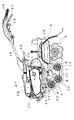
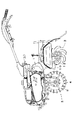
尚、本発明におけるクローラ走行装置2は、その形状を限定することなくあらゆる形状のものとすればよく、望ましくは、図1,図2に示す如く前方を上方へ傾斜させた側面視船底型の形状、若しくは図3に示す如く側面視三角型の形状とするのがよい。
又、請求の範囲の項に図面との対象と便利にする為に番号を記すが、この記入により本発明は添付図面の構造に限定されるものではない。
【図面の簡単な説明】
【図1】 本発明実施例における全体側面図。
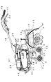
【図2】 本発明実施例におけるフロントカバー10を収納又は取外した状態を示す全体側面図。
【図3】 本発明実施例における全体側面図。
【図4】 本発明実施例における全体平面図。
【図5】 本発明実施例における主要部の一部切断した正面図。
【図6】 従来例を示す全体側面図。
【図7】 (a)本発明実施例における主要部の正面図。
(b)従来例の一部の正面図。
【符号の説明】
1 ギヤケース
2 走行装置
3 ロータリ
4 走行伝動ケース
5 駆動スプロケット
6 転輪
7 クローラベルト
13 ロータリカバー[0001]
BACKGROUND OF THE INVENTION
The present invention relates to a traveling device for a walking type management machine that is a working machine used for a farming work in a field and in which an operator performs a steering operation while walking on the rear side of the machine body.
[0002]
[Prior art]
As shown in FIG. 6, the conventional walking type management machine generally has a structure in which a single wheel
[0003]
[Problems to be solved by the invention]
However, in the walking type management machine having the above-described configuration, in order to prevent the soil from being scattered forward by the rear rotary, the protruding length between the front end of the rotary cover and the rear of the traveling device, that is, between the rotary and the traveling device. An adjustable front cover is attached, but the front cover is attached to the front traveling device and the rear rotary so that it does not get in the way of the work and is shortly attached to the upper front of the rotary. .
For this reason, the soil that is scattered forward by the rotary is somewhat prevented by the front cover, but most of the soil tries to fly further forward through the lower part of the short front cover. At this time, since the front traveling device is a cultivated tire having a narrow left and right width A, there is a problem that the soil easily scatters forward without hindering the scattering.
An object of the present invention is to solve the above-mentioned problems with a simple configuration and to provide a walking type management machine that reliably prevents the scattering of soil forward by a rotary.
[0004]
[Means for Solving the Problems]
In a walking-type management machine in which one
[0005]
[Action and effect of the invention]
In the walking type management machine of the present invention, the crawler traveling
Since the crawler traveling
Further, the crawler traveling
[0006]
【Example】
Next, embodiments of the present invention will be described with reference to the drawings.
The
The
A rotary cover 13 is provided above the
[0007]
A
The
[0008]
A
A
[0009]
The
A plate-
The
[0010]
When the plowing work is performed with the walking type management machine having the above configuration, the plowing work is performed with the
In particular, when the
At this time, the crawler traveling
Further, the grounding length of the
[0011]
In some cases, the walking type management machine travels through a narrow groove M formed in the field, and the groove width W that the walking type management machine travels at this time is the center of the left and right sides of the machine body, that is, the
[0012]
It should be noted that the
In addition, although numbers are given in the claims to make the objects of the drawings convenient for convenience, the present invention is not limited to the structure of the attached drawings by this entry.
[Brief description of the drawings]
FIG. 1 is an overall side view of an embodiment of the present invention.
FIG. 2 is an overall side view showing a state in which the
FIG. 3 is an overall side view of an embodiment of the present invention.
FIG. 4 is an overall plan view of an embodiment of the present invention.
FIG. 5 is a partially cut front view of the main part in the embodiment of the present invention.
FIG. 6 is an overall side view showing a conventional example.
FIG. 7A is a front view of a main part in an embodiment of the present invention.
(B) The front view of a part of a conventional example.
[Explanation of symbols]
DESCRIPTION OF
Claims (1)
Priority Applications (1)
| Application Number | Priority Date | Filing Date | Title |
|---|---|---|---|
| JP17973499A JP4126636B2 (en) | 1999-06-25 | 1999-06-25 | Traveling device for walking type management machine |
Applications Claiming Priority (1)
| Application Number | Priority Date | Filing Date | Title |
|---|---|---|---|
| JP17973499A JP4126636B2 (en) | 1999-06-25 | 1999-06-25 | Traveling device for walking type management machine |
Publications (3)
| Publication Number | Publication Date |
|---|---|
| JP2001008501A JP2001008501A (en) | 2001-01-16 |
| JP2001008501A5 JP2001008501A5 (en) | 2006-06-08 |
| JP4126636B2 true JP4126636B2 (en) | 2008-07-30 |
Family
ID=16070945
Family Applications (1)
| Application Number | Title | Priority Date | Filing Date |
|---|---|---|---|
| JP17973499A Expired - Lifetime JP4126636B2 (en) | 1999-06-25 | 1999-06-25 | Traveling device for walking type management machine |
Country Status (1)
| Country | Link |
|---|---|
| JP (1) | JP4126636B2 (en) |
Cited By (2)
| Publication number | Priority date | Publication date | Assignee | Title |
|---|---|---|---|---|
| CN103081593A (en) * | 2013-03-01 | 2013-05-08 | 湖南春燕机械制造有限公司 | Multi-functional rotary tillage excavator with self-propelled track |
| CN104255100A (en) * | 2014-09-30 | 2015-01-07 | 湖南省烟草公司郴州市公司 | Tracked chassis for field management machine |
Families Citing this family (3)
| Publication number | Priority date | Publication date | Assignee | Title |
|---|---|---|---|---|
| JP5097484B2 (en) * | 2007-09-11 | 2012-12-12 | ヤンマー株式会社 | Management machine |
| CN106068698B (en) * | 2016-07-28 | 2018-02-16 | 刘丙炎 | A kind of crawler-type rotary cultivator |
| CN111659719A (en) * | 2020-06-24 | 2020-09-15 | 沈阳大学 | Soil repairing agent distributing machine |
-
1999
- 1999-06-25 JP JP17973499A patent/JP4126636B2/en not_active Expired - Lifetime
Cited By (2)
| Publication number | Priority date | Publication date | Assignee | Title |
|---|---|---|---|---|
| CN103081593A (en) * | 2013-03-01 | 2013-05-08 | 湖南春燕机械制造有限公司 | Multi-functional rotary tillage excavator with self-propelled track |
| CN104255100A (en) * | 2014-09-30 | 2015-01-07 | 湖南省烟草公司郴州市公司 | Tracked chassis for field management machine |
Also Published As
| Publication number | Publication date |
|---|---|
| JP2001008501A (en) | 2001-01-16 |
Similar Documents
| Publication | Publication Date | Title |
|---|---|---|
| EP1329611B1 (en) | Working machine having front-rotary working unit | |
| US5562166A (en) | Garden tiller | |
| JP4126636B2 (en) | Traveling device for walking type management machine | |
| US3559414A (en) | Apparatus and method for laying flexible cable | |
| JP3364649B2 (en) | Traveling device for walking type management machine | |
| JP2001238504A (en) | Front rotary tiller | |
| JP5478964B2 (en) | Agricultural machine | |
| JP3371907B2 (en) | Traveling device for walking type management machine | |
| JP3364652B2 (en) | Traveling device for walking type management machine | |
| JP3364647B2 (en) | Walking management machine | |
| JP3386423B2 (en) | Traveling device for walking type management machine | |
| JP2004008082A (en) | Simple sulky tending working machine | |
| JP3979520B2 (en) | Combined tillage device | |
| JP3614504B2 (en) | Dash prevention device for management machine | |
| JP3371906B2 (en) | Walking management machine | |
| JP3533656B2 (en) | Walking mower | |
| JPH1084704A (en) | Walk-type tilling machine | |
| JP2001025304A (en) | Crawler mobile unit for walking type tending machine | |
| JP3547323B2 (en) | Mower | |
| JP2000279002A (en) | Tending machine | |
| JP4318823B2 (en) | 畦 coating machine | |
| JPH0884502A (en) | Rotary working machine | |
| JP2573488Y2 (en) | Tilling machine | |
| JP2004268618A (en) | Walking type agricultural working machine | |
| JP4611188B2 (en) | Walking type management machine |
Legal Events
| Date | Code | Title | Description |
|---|---|---|---|
| A521 | Written amendment |
Free format text: JAPANESE INTERMEDIATE CODE: A523 Effective date: 20060411 |
|
| A621 | Written request for application examination |
Free format text: JAPANESE INTERMEDIATE CODE: A621 Effective date: 20060411 |
|
| A977 | Report on retrieval |
Free format text: JAPANESE INTERMEDIATE CODE: A971007 Effective date: 20071012 |
|
| A131 | Notification of reasons for refusal |
Free format text: JAPANESE INTERMEDIATE CODE: A131 Effective date: 20071016 |
|
| A521 | Written amendment |
Free format text: JAPANESE INTERMEDIATE CODE: A523 Effective date: 20071130 |
|
| TRDD | Decision of grant or rejection written | ||
| A01 | Written decision to grant a patent or to grant a registration (utility model) |
Free format text: JAPANESE INTERMEDIATE CODE: A01 Effective date: 20080418 |
|
| A01 | Written decision to grant a patent or to grant a registration (utility model) |
Free format text: JAPANESE INTERMEDIATE CODE: A01 |
|
| A61 | First payment of annual fees (during grant procedure) |
Free format text: JAPANESE INTERMEDIATE CODE: A61 Effective date: 20080501 |
|
| FPAY | Renewal fee payment (event date is renewal date of database) |
Free format text: PAYMENT UNTIL: 20110523 Year of fee payment: 3 |
|
| R150 | Certificate of patent or registration of utility model |
Ref document number: 4126636 Country of ref document: JP Free format text: JAPANESE INTERMEDIATE CODE: R150 Free format text: JAPANESE INTERMEDIATE CODE: R150 |
|
| FPAY | Renewal fee payment (event date is renewal date of database) |
Free format text: PAYMENT UNTIL: 20110523 Year of fee payment: 3 |
|
| FPAY | Renewal fee payment (event date is renewal date of database) |
Free format text: PAYMENT UNTIL: 20120523 Year of fee payment: 4 |
|
| R250 | Receipt of annual fees |
Free format text: JAPANESE INTERMEDIATE CODE: R250 |
|
| FPAY | Renewal fee payment (event date is renewal date of database) |
Free format text: PAYMENT UNTIL: 20120523 Year of fee payment: 4 |
|
| FPAY | Renewal fee payment (event date is renewal date of database) |
Free format text: PAYMENT UNTIL: 20130523 Year of fee payment: 5 |
|
| R250 | Receipt of annual fees |
Free format text: JAPANESE INTERMEDIATE CODE: R250 |
|
| FPAY | Renewal fee payment (event date is renewal date of database) |
Free format text: PAYMENT UNTIL: 20130523 Year of fee payment: 5 |
|
| FPAY | Renewal fee payment (event date is renewal date of database) |
Free format text: PAYMENT UNTIL: 20140523 Year of fee payment: 6 |
|
| R250 | Receipt of annual fees |
Free format text: JAPANESE INTERMEDIATE CODE: R250 |
|
| R250 | Receipt of annual fees |
Free format text: JAPANESE INTERMEDIATE CODE: R250 |
|
| R250 | Receipt of annual fees |
Free format text: JAPANESE INTERMEDIATE CODE: R250 |
|
| R250 | Receipt of annual fees |
Free format text: JAPANESE INTERMEDIATE CODE: R250 |
|
| R250 | Receipt of annual fees |
Free format text: JAPANESE INTERMEDIATE CODE: R250 |
|
| R250 | Receipt of annual fees |
Free format text: JAPANESE INTERMEDIATE CODE: R250 |
|
| R250 | Receipt of annual fees |
Free format text: JAPANESE INTERMEDIATE CODE: R250 |
|
| EXPY | Cancellation because of completion of term |