JP4120787B2 - Series arrangement linear motor - Google Patents
Series arrangement linear motor Download PDFInfo
- Publication number
- JP4120787B2 JP4120787B2 JP2002295049A JP2002295049A JP4120787B2 JP 4120787 B2 JP4120787 B2 JP 4120787B2 JP 2002295049 A JP2002295049 A JP 2002295049A JP 2002295049 A JP2002295049 A JP 2002295049A JP 4120787 B2 JP4120787 B2 JP 4120787B2
- Authority
- JP
- Japan
- Prior art keywords
- mover
- linear motor
- movers
- terminal
- terminals
- Prior art date
- Legal status (The legal status is an assumption and is not a legal conclusion. Google has not performed a legal analysis and makes no representation as to the accuracy of the status listed.)
- Expired - Fee Related
Links
Images


Classifications
-
- H—ELECTRICITY
- H02—GENERATION; CONVERSION OR DISTRIBUTION OF ELECTRIC POWER
- H02K—DYNAMO-ELECTRIC MACHINES
- H02K41/00—Propulsion systems in which a rigid body is moved along a path due to dynamo-electric interaction between the body and a magnetic field travelling along the path
- H02K41/02—Linear motors; Sectional motors
- H02K41/03—Synchronous motors; Motors moving step by step; Reluctance motors
-
- H—ELECTRICITY
- H02—GENERATION; CONVERSION OR DISTRIBUTION OF ELECTRIC POWER
- H02K—DYNAMO-ELECTRIC MACHINES
- H02K5/00—Casings; Enclosures; Supports
- H02K5/04—Casings or enclosures characterised by the shape, form or construction thereof
- H02K5/22—Auxiliary parts of casings not covered by groups H02K5/06-H02K5/20, e.g. shaped to form connection boxes or terminal boxes
- H02K5/225—Terminal boxes or connection arrangements
-
- H—ELECTRICITY
- H02—GENERATION; CONVERSION OR DISTRIBUTION OF ELECTRIC POWER
- H02P—CONTROL OR REGULATION OF ELECTRIC MOTORS, ELECTRIC GENERATORS OR DYNAMO-ELECTRIC CONVERTERS; CONTROLLING TRANSFORMERS, REACTORS OR CHOKE COILS
- H02P25/00—Arrangements or methods for the control of AC motors characterised by the kind of AC motor or by structural details
- H02P25/02—Arrangements or methods for the control of AC motors characterised by the kind of AC motor or by structural details characterised by the kind of motor
- H02P25/06—Linear motors
- H02P25/062—Linear motors of the induction type
Landscapes
- Engineering & Computer Science (AREA)
- Power Engineering (AREA)
- Physics & Mathematics (AREA)
- Chemical & Material Sciences (AREA)
- Combustion & Propulsion (AREA)
- Electromagnetism (AREA)
- Linear Motors (AREA)
Description
【0001】
【発明の属する技術分野】
本発明は、一つの移動体を複数のリニアモータ可動子で駆動する直列配置リニアモータの構造および位相配置に関するものである。
【0002】
【従来の技術】
図6は従来のリニアモータを示している。
図において、1’は1個の電機子で構成される従来のリニアモータの可動子、6’は複数の永久磁石よりなる界磁で構成される固定子である。なお、電機子は多相平衡巻線を有するものとなっており、リニアモータは可動子1’と固定子6’がギャップを介して対向配置されている。
図6に示すように、従来のリニアモータは一つの移動体に対して一つのリニアモータ可動子1’で駆動する機構になっていた(例えば、本出願人が出願した特許文献1を参照のこと。)。
【0003】
【特許文献1】
特開2000−308328 号公報
【0004】
これは電機子コイルの渡り線および中性点の接続処理を容易にし、コアブロックの単位体積当たりの推力を大きくできるリニアモータにするために、界磁用の永久磁石と磁気的空隙を介して対向する電機子を備え、この電機子が、推力方向に複数に分割されたコアブロックで構成してなる電機子コアと電機子コイルを有するもので、各々のコアブロックに巻装される電機子コイルは、コイル導体の巻始め部分と巻終わり部分が配線パターンを有する配線基板に接続されたものである。
【0005】
【発明が解決しようとする課題】
しかしながら、推力を大きくできるこのリニアモータにも限界がある。
大形の工作機械等の駆動にリニアモータが用いられた場合、必要推力が40000Nになるものもあり、この場合、磁石とコア間の磁気吸引力も120000N(12t)と強大になる。ところが図6のような1個の電機子を備えるリニアモータで上記必要推力を得ようとすると、推力の増大に伴うコギングの問題や、電機子の発熱の問題が生じたりして、このような大形機械の駆動に対処しきれなかった。
仮に1個の電機子で設計すると、可動子(電機子)重量が250kg以上となり、ハンドリング等の問題が大きくなる。また、モータの磁石の吸引力増大により、磁石の組立に時間がかかるという問題があった。
さらに故障の場合、その被害金額も大きくなった。
本発明は、上記課題を解決するためになされたものであって、大形機械の駆動ができしかもコギング力を相殺し、可動子組み立てが容易で、可動子の熱保護を容易にできる安価な直列配置リニアモータを提供することにある。
【0006】
【課題を解決するための手段】
上記課題を解決するために、請求項1記載の直列配置リニアモータの発明は、多相平衡巻線を有する電機子で構成される複数の可動子と、永久磁石もしくは2次導体を有する固定子から構成されており、前記複数の可動子を、同一の前記固定子上にギャップを介して対向配置し、かつ、該各可動子の各多相平衡巻線を直列接続させており、前記可動子の前後端に接続用端子を配備し、最終可動子の後端端子の多層巻線端子を相互に短絡接続(中性点)処理した直列配置リニアモータにおいて、前記複数の可動子には各々サーミスタが内蔵されており、該各サーミスタも全て直列接続させるように外部端子を前記可動子前後端に接続端子を配備させたことを特徴とする。
請求項2記載の発明は、請求項1記載の直列配置リニアモータにおいて、前記複数の可動子の相数を3相とし、可動子数を3の倍数個とした中で、各可動子間の位相差が電気角120°もしくは240°の位相ズレをもたせ、かつ各可動子の前後端にある接続端子の繋ぎをも120°もしくは240°位相をもたせる接続にしたことを特徴とする。
このように本発明は、同一固定子上に複数の可動子を配置させ、これらの可動子の多相平衡巻線を直列接続させたことで、一つの移動体を駆動できる直列配置リニアモータとなっている。
そして直列接続をすることにより、並列接続の場合に起こる各可動子の、若干の位相ズレによる循環電流の発生を防止することができ、また推力容量に異なるリニア可動子を組み合わせた配列が可能になる。
【0007】
【発明の実施の形態】
以下、本発明の実施の形態を図に基づいて詳細に説明する。
図1は本発明の実施の形態に係るリニアモータの概念斜視図である。
図において、1a〜1cは電機子で構成される第1のリニアモータ可動子群、1d〜1fは電機子で構成される第2のリニアモータ可動子群、2Aおよび2Bはそれぞれ第1および第2の前記リニアモータ可動子群を駆動するパワーアンプ、6Aおよび6Bはそれぞれ第1および第2の前記リニアモータ可動子群を載置する固定子である。
図に示すように、このリニアモータは図で左右の固定子6Aおよび6B上に2つの可動子群1a〜1c、1d〜1fをドライバである2つのパワーアンプ2Aおよび2Bで駆動する例である。
【0008】
図2は図1のリニアモータ可動子群の各リニア可動子単体に施される平衡3相巻線の例である。
図において、リニア可動子単体には前端(図で左側)に端子U,V,Wと後端(図で右側)の端子X,Y,Zがあり、端子UとX間に三相巻線のうちの1相のコイルが2個(RU1、RU2)、同じく端子VとY間に三相巻線のうちの他の1相のコイルが2個(RV1、RV2)、そして端子WとZ間に三相巻線の残りの1相のコイルが2個(RW1、RW2)がそれぞれ並列に接続されている。
また、リニア可動子単体の前端の端子Aと後端の端子aとの間に、2個のサーミスタ41(THa)、42(THb)が直列接続されており、一方のサーミスタ41は端子U−V間に、他方のサーミスタ42はV−W間に配置され、それぞれの温度を検知している。
そして、サーミスタ線のバイパス線も前端の端子Bと後端の端子b間に接続されている。
さらに、前端の端子Eと後端の端子e間には、電機子コア(図示せず)に接続されたアース線が接続されている。
【0009】
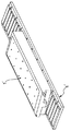
図3は、図2のリニア可動子の上視外観を示す。
図において、1はリニア可動子単体で、51は前端端子(図で左側)、52は後端端子(図で右側)である。
内部には図2で説明したように、端子UとX間に2個のU相コイル、端子VとY間に2個のV相コイル、そして端子WとZ間に2個のW相コイルががそれぞれ並列に接続されている。また、端子Aと端子aとの間に2個のサーミスタが直列接続されており、端子Bと端子b間にこのサーミスタ線のバイパス線が接続されている。前端の端子Eと後端の端子e間には電機子コア(図示せず)に接続されたアース線が接続されている。
【0010】
図4は、図2の可動子を3個直列に接続した場合の各可動子間の接続関係を示す。
各可動子1a〜1c間は、240°の整数倍nの電気角位相で配置されている。
先端の可動子1aの前端端子51aの端子U、端子V、端子Wに外部から給電される。
可動子1a内では、図2で説明したように、端子Uは2個並列に接続された相コイルRu1、Ru2を経て後端端子52aの端子Xに接続され、端子Vは2個並列に接続された相コイルRv1、Rv2を経て後端端子52aの端子Yに接続され、端子Wは2個並列に接続された相コイルRw1、Rw2を経て後端端子52aの端子Zに接続されている。
次に、可動子1aの後端端子52aの端子X、Y、Zはそれぞれ次の可動子1bの前端端子51bの端子U、V、Wに接続される。ところが可動子1b内では、端子Uは可動子1aの場合の相コイルRu1、Ru2ではなくて、電気角で120°隣の相コイルRv1、Rv2を経て後端端子52bの端子Xに接続されている。以下同様に、端子Vは120°隣の相コイルRw1、Rw2を経て後端端子52bの端子Yに接続され、端子Wは120°隣の相コイルRu1、Ru2を経て後端端子52bの端子Zに接続されている。
そして、可動子1bの後端端子52bの端子X、Y、Zはそれぞれ次の可動子1cの前端端子51cの端子U、V、Wに接続される。ところが可動子1c内では、端子Uは可動子1bの場合の相コイルRv1、Rv2ではなくて、それより電気角で120°隣の相コイルRw1、Rw2を経て後端端子52cの端子Xに接続されている。以下同様に、端子Vは120°隣の相コイルRu1、Ru2を経て後端端子52cの端子Yに接続され、端子Wは120°隣の相コイルRv1、Rv2を経て後端端子52cの端子Zに接続されている。
このように、各可動子1a〜1cの各相巻線の相Ru、Rv、Rwの各順番は、第1可動子1aがRu−Rv−Rwとなれば、第2可動子1bはRw−Ru−Rv、第3可動子1cはRv−Rw−Ruとなるように接続線で接続されている。 そして最終可動子となる第3可動子1cの後端ターミナル52cのX、Y、Z端子はそれぞれ短絡されることで中性点処理されている。
【0011】
また、各可動子1a〜1cの各サーミスタ4の前後の端子もそれぞれ接続され、最終可動子となる第3可動子1cのa−b端子を短絡することで、全てのサーミスタ素子が直列接続される。
これにより、いずれかの可動子の、いずれかの相巻線温度が異常になっても、正しく検知し、温度保護をかけることが可能になる。
このように、各可動子1a〜1c間は240°(または120°)の整数倍nの電気角位相で配置接続することによって、コギング力を相殺することが可能になる。
【0012】
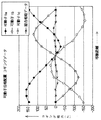
図5は、コギング相殺の関係を示した図である。
図において、縦軸はコギング推力(N)、横軸は移動距離を表している。
例えば図1に示した各可動子1a〜1cのコギング推力は、前後端部の磁気回路の不平衡により、図のようなそれぞれ位相および横軸のシフトしたサイン波形のコギング推力が生じている。
ところがこれを図4で述べたように、各可動子1a〜1c間の位相を240°ずらすことにより、各コギング推力は相殺しあうため、結果的に図5の総合相殺データのように僅かな変動に抑えることができる。
【0013】
【発明の効果】
以上述べたように本発明によれば、大推力を必要とするアプリケーションであっても、複数個のリニア可動子での駆動構造にすることで、一つの可動子重量は、軽くなり、組み立て時のハンドリングは容易になる。
また、不慮の事故により可動子が焼損、破損した場合でも、交換、補修費用は、安価になる利点がでる。
さらには、実施の形態のように複数個の可動子に、それぞれ120°もしくは240°の位相差を持たせる配置、接続させることでコギング力を相殺することが可能になる。
サーミスタ等の温度保護素子も、全体で直列接続されることにより、どれか一つの(可動子)電機子の温度が異常になった場合でも保護がかかるようになっている。
【図面の簡単な説明】
【図1】本発明の実施の形態に係るリニアモータの概念斜視図である。
【図2】図1のリニアモータ可動子群の各リニア可動子単体に施される平衡3相巻線の接続例である。
【図3】図2のリニア可動子の上視外観図である。
【図4】図2の可動子を3個直列に接続した場合の各可動子間の接続関係図である。
【図5】可動子のコギング推力とコギング相殺の関係を示した図である。
【図6】従来のリニアモータの外観斜視図である。
【符号の説明】
1、1a〜1f:可動子
2、2A、2B:ドライバ
3、3A、3B:各相巻線
4、41、42:サーミスタ
5:51a〜51c:前端端子
52a〜52c:後端端子
6、6A、6B:固定子[0001]
BACKGROUND OF THE INVENTION
The present invention relates to the structure and phase arrangement of a serially arranged linear motor that drives one moving body with a plurality of linear motor movers.
[0002]
[Prior art]
FIG. 6 shows a conventional linear motor.
In the figure, 1 ′ is a mover of a conventional linear motor composed of one armature, and 6 ′ is a stator composed of a field composed of a plurality of permanent magnets. The armature has a multiphase balanced winding, and in the linear motor, the mover 1 ′ and the stator 6 ′ are opposed to each other with a gap interposed therebetween.
As shown in FIG. 6, the conventional linear motor has a mechanism that is driven by one linear motor movable element 1 ′ with respect to one moving body (see, for example, Patent Document 1 filed by the present applicant). thing.).
[0003]
[Patent Document 1]
Japanese Patent Laid-Open No. 2000-308328
This facilitates the connection process of the jumper wire and neutral point of the armature coil, and in order to make a linear motor that can increase the thrust per unit volume of the core block, through a permanent magnet for the field and a magnetic gap. Armatures having armature cores and armature coils, each of which has armature cores and armature coils, each of which has an armature that is opposed to each other and is divided into a plurality of core blocks in the thrust direction. The coil is formed by connecting a winding start portion and a winding end portion of a coil conductor to a wiring board having a wiring pattern.
[0005]
[Problems to be solved by the invention]
However, there is a limit to this linear motor that can increase the thrust.
When a linear motor is used to drive a large machine tool or the like, there are some which require 40000 N of thrust, and in this case, the magnetic attractive force between the magnet and the core becomes as strong as 120,000 N (12 t). However, when trying to obtain the above required thrust with a linear motor having one armature as shown in FIG. 6, there is a problem of cogging due to an increase in thrust and a problem of heat generation of the armature. I could not cope with the drive of a large machine.
If it is designed with one armature, the weight of the mover (armature) becomes 250 kg or more, and problems such as handling increase. Further, there is a problem that it takes time to assemble the magnet due to an increase in the attractive force of the magnet of the motor.
In the case of a failure, the amount of damage increased.
The present invention has been made to solve the above-described problems, and can be used to drive a large-sized machine, cancels cogging force, facilitates assembly of the mover, and facilitates thermal protection of the mover. It is to provide a linear motor arranged in series.
[0006]
[Means for Solving the Problems]
In order to solve the above-mentioned problems, a serially arranged linear motor according to a first aspect of the present invention is a stator having a plurality of movers composed of armatures having multiphase balanced windings and permanent magnets or secondary conductors. are composed of a plurality of movable elements, opposed disposed through a gap on the same said stator, and which is connected in series each polyphase balancing windings of each of the movable element, the movable In the series arrangement linear motor in which connection terminals are arranged at the front and rear ends of the child and the multilayer winding terminals of the rear end terminal of the final mover are short-circuited to each other (neutral point), A thermistor is built in, and external terminals are connected to the front and rear ends of the mover so that all the thermistors are connected in series .
The invention according to claim 2 is the serially arranged linear motor according to claim 1, wherein the number of phases of the plurality of movers is three and the number of movers is a multiple of three. The phase difference has an electrical angle of 120 ° or 240 °, and the connecting terminals at the front and rear ends of each movable element are also connected to have a phase of 120 ° or 240 ° .
As described above, the present invention provides a series arrangement linear motor capable of driving one moving body by arranging a plurality of movers on the same stator and connecting the multiphase balanced windings of these movers in series. It has become.
And by connecting in series, it is possible to prevent the occurrence of circulating current due to slight phase shift of each mover that occurs in the case of parallel connection, and it is possible to arrange a combination of different linear movers for thrust capacity Become.
[0007]
DETAILED DESCRIPTION OF THE INVENTION
Hereinafter, embodiments of the present invention will be described in detail with reference to the drawings.
FIG. 1 is a conceptual perspective view of a linear motor according to an embodiment of the present invention.
In the figure, 1a to 1c are a first linear motor movable element group composed of armatures, 1d to 1f are a second linear motor movable element group composed of armatures, and 2A and 2B are first and first elements, respectively.
As shown in the figure, this linear motor is an example in which two movable element groups 1a to 1c and 1d to 1f are driven by two
[0008]
FIG. 2 is an example of a balanced three-phase winding applied to each linear mover of the linear motor mover group of FIG.
In the figure, the linear mover has terminals U, V, W at the front end (left side in the figure) and terminals X, Y, Z at the rear end (right side in the figure), and a three-phase winding between the terminals U and X. 2 of one phase (RU1, RU2), two other one-phase coils (RV1, RV2) of three-phase windings between terminals V and Y, and terminals W and Z Two remaining one-phase coils (RW1, RW2) of the three-phase winding are connected in parallel.
Further, two thermistors 41 (THa) and 42 (THb) are connected in series between the front end terminal A and the rear end terminal a of the linear movable element alone, and one
The bypass line of the thermistor line is also connected between the front terminal B and the rear terminal b.
Further, a ground wire connected to an armature core (not shown) is connected between the front end terminal E and the rear end terminal e.
[0009]
FIG. 3 shows a top view of the linear movable element shown in FIG.
In the figure, 1 is a single linear movable element, 51 is a front end terminal (left side in the figure), and 52 is a rear end terminal (right side in the figure).
As shown in FIG. 2, there are two U-phase coils between terminals U and X, two V-phase coils between terminals V and Y, and two W-phase coils between terminals W and Z. Are connected in parallel. Further, two thermistors are connected in series between the terminal A and the terminal a, and a bypass line of the thermistor line is connected between the terminal B and the terminal b. A ground wire connected to an armature core (not shown) is connected between the front terminal E and the rear terminal e.
[0010]
FIG. 4 shows a connection relationship between the movers when the three movers of FIG. 2 are connected in series.
Between each mover 1a-1c, it arrange | positions by the electrical angle phase of the integral multiple n of 240 degrees.
Power is supplied from the outside to the terminal U, the terminal V, and the terminal W of the
In the mover 1a, as described in FIG. 2, the terminal U is connected to the terminal X of the
Next, the terminals X, Y, and Z of the
The terminals X, Y, and Z of the
As described above, the order of the phases Ru, Rv, and Rw of the phase windings of the movers 1a to 1c is such that if the first mover 1a becomes Ru-Rv-Rw, the
[0011]
Further, the front and rear terminals of each thermistor 4 of each of the movers 1a to 1c are also connected, and all the thermistor elements are connected in series by short-circuiting the ab terminals of the
As a result, even if any of the phase winding temperatures of any of the movers becomes abnormal, it is possible to correctly detect and protect the temperature.
Thus, the cogging force can be canceled by arranging and connecting the movable elements 1a to 1c with an electrical angle phase of an integer multiple n of 240 ° (or 120 °).
[0012]
FIG. 5 is a diagram showing the relationship of cogging cancellation.
In the figure, the vertical axis represents cogging thrust (N), and the horizontal axis represents the movement distance.
For example, the cogging thrust of each of the movers 1a to 1c shown in FIG. 1 is caused by a cogging thrust having a sine waveform shifted in phase and horizontal axis as shown in FIG.
However, as described with reference to FIG. 4, since the cogging thrusts cancel each other by shifting the phase between the movable elements 1a to 1c by 240 °, the result is a slight amount as shown in the total cancellation data in FIG. It can be suppressed to fluctuation.
[0013]
【The invention's effect】
As described above, according to the present invention, even in an application that requires a large thrust, by adopting a drive structure with a plurality of linear movers, the weight of one mover can be reduced, and at the time of assembly. Handling becomes easy.
In addition, even if the mover is burned or damaged due to an unexpected accident, the replacement and repair costs can be reduced.
Furthermore, the cogging force can be canceled by arranging and connecting a plurality of movers with a phase difference of 120 ° or 240 °, respectively, as in the embodiment.
A temperature protection element such as a thermistor is also connected in series as a whole so that even when the temperature of any one (mover) armature becomes abnormal, protection is applied.
[Brief description of the drawings]
FIG. 1 is a conceptual perspective view of a linear motor according to an embodiment of the present invention.
2 is a connection example of balanced three-phase windings applied to each linear mover of the linear motor mover group in FIG. 1;
FIG. 3 is a top view of the linear movable element shown in FIG. 2 as viewed from above.
4 is a connection relation diagram between the movable elements when three movable elements of FIG. 2 are connected in series. FIG.
FIG. 5 is a diagram showing a relationship between a cogging thrust of a mover and cogging cancellation.
FIG. 6 is an external perspective view of a conventional linear motor.
[Explanation of symbols]
1, 1a to 1f:
Claims (2)
前記複数の可動子を、同一の前記固定子上にギャップを介して対向配置し、かつ、該各可動子の各多相平衡巻線を直列接続させており、
前記可動子の前後端に接続用端子を配備し、最終可動子の後端端子の多層巻線端子を相互に短絡接続(中性点)処理した直列配置リニアモータにおいて、
前記複数の可動子には各々サーミスタが内蔵されており、該各サーミスタも全て直列接続させるように外部端子を前記可動子前後端に接続端子を配備させたことを特徴とする直列配置リニアモータ。It is composed of a plurality of movers composed of armatures having multiphase balanced windings, and a stator having permanent magnets or secondary conductors ,
Wherein the plurality of movable elements, opposed disposed through a gap on the same said stator, and which is connected in series each polyphase balancing windings of each of the movable element,
In the serial arrangement linear motor in which connection terminals are arranged at the front and rear ends of the mover, and the multi-layer winding terminals of the rear end terminal of the final mover are short-circuited to each other (neutral point),
A series-arranged linear motor, wherein each of the plurality of movers has a built-in thermistor, and external terminals are arranged at the front and rear ends of the mover so that all the thermistors are connected in series .
Priority Applications (7)
| Application Number | Priority Date | Filing Date | Title |
|---|---|---|---|
| JP2002295049A JP4120787B2 (en) | 2002-10-08 | 2002-10-08 | Series arrangement linear motor |
| CN200380101120A CN100576705C (en) | 2002-10-08 | 2003-10-06 | The configured in series linear electric motors |
| KR1020057005917A KR100983764B1 (en) | 2002-10-08 | 2003-10-06 | Tandem arrangement linear motor |
| DE10393464T DE10393464T5 (en) | 2002-10-08 | 2003-10-06 | Linear motor with serial configuration |
| US10/530,674 US7291941B2 (en) | 2002-10-08 | 2003-10-06 | Tandem arrangement linear motor |
| PCT/JP2003/012797 WO2004034556A1 (en) | 2002-10-08 | 2003-10-06 | Tandem arrangement linear motor |
| TW092127827A TW200410473A (en) | 2002-10-08 | 2003-10-07 | Serially-arranged linear motor |
Applications Claiming Priority (1)
| Application Number | Priority Date | Filing Date | Title |
|---|---|---|---|
| JP2002295049A JP4120787B2 (en) | 2002-10-08 | 2002-10-08 | Series arrangement linear motor |
Publications (2)
| Publication Number | Publication Date |
|---|---|
| JP2004135384A JP2004135384A (en) | 2004-04-30 |
| JP4120787B2 true JP4120787B2 (en) | 2008-07-16 |
Family
ID=32089201
Family Applications (1)
| Application Number | Title | Priority Date | Filing Date |
|---|---|---|---|
| JP2002295049A Expired - Fee Related JP4120787B2 (en) | 2002-10-08 | 2002-10-08 | Series arrangement linear motor |
Country Status (7)
| Country | Link |
|---|---|
| US (1) | US7291941B2 (en) |
| JP (1) | JP4120787B2 (en) |
| KR (1) | KR100983764B1 (en) |
| CN (1) | CN100576705C (en) |
| DE (1) | DE10393464T5 (en) |
| TW (1) | TW200410473A (en) |
| WO (1) | WO2004034556A1 (en) |
Families Citing this family (6)
| Publication number | Priority date | Publication date | Assignee | Title |
|---|---|---|---|---|
| KR100795208B1 (en) * | 2006-03-16 | 2008-01-16 | 자화전자 주식회사 | A Linear Motor Having Field Permanent Magnet And Armature With Salient Poles And Method for Manufacture Thereof |
| US7692768B2 (en) * | 2006-06-29 | 2010-04-06 | Nikon Corporation | Iron core motor driven automatic reticle blind |
| CN101984551B (en) * | 2010-11-11 | 2012-06-13 | 四川长征机床集团有限公司 | Method for expanding output range of thrust of linear motor |
| CN102158040B (en) * | 2011-03-25 | 2012-12-05 | 哈尔滨工业大学 | High-accuracy electromagnetic force controlled linear motor and control system thereof |
| CN102195439B (en) * | 2011-05-26 | 2013-06-12 | 清华大学 | Multi-stator multi-rotor array linear motor driving device |
| US20190061558A1 (en) * | 2017-08-31 | 2019-02-28 | Rockwell Automation Technologies, Inc. | Systems and methods for sensing parameters on movers in linear motor systems |
Family Cites Families (8)
| Publication number | Priority date | Publication date | Assignee | Title |
|---|---|---|---|---|
| US4958115A (en) * | 1988-11-28 | 1990-09-18 | At&T Bell Laboratories | Capacitively commutated brushless DC servomotors |
| EP1056187A4 (en) * | 1998-02-13 | 2005-11-02 | Yaskawa Denki Seisakusho Kk | Linear motor |
| JP2000308328A (en) | 1999-04-20 | 2000-11-02 | Yaskawa Electric Corp | Linear motor |
| JP4527826B2 (en) * | 2000-01-28 | 2010-08-18 | Thk株式会社 | High thrust linear motor and manufacturing method thereof |
| DE10007777A1 (en) * | 2000-02-21 | 2001-09-20 | Magnet Motor Gmbh | Permanent magnet excited electrical machine and method for operating such a machine |
| JP3856196B2 (en) * | 2000-10-26 | 2006-12-13 | 株式会社安川電機 | Armature coil connecting device for linear motor |
| JP2002171741A (en) | 2000-11-30 | 2002-06-14 | Shicoh Eng Co Ltd | Linear motor |
| US6592254B2 (en) * | 2001-06-26 | 2003-07-15 | Mamac Systems, Inc. | Multiple point averaging duct temperature sensor |
-
2002
- 2002-10-08 JP JP2002295049A patent/JP4120787B2/en not_active Expired - Fee Related
-
2003
- 2003-10-06 DE DE10393464T patent/DE10393464T5/en not_active Withdrawn
- 2003-10-06 CN CN200380101120A patent/CN100576705C/en not_active Expired - Fee Related
- 2003-10-06 KR KR1020057005917A patent/KR100983764B1/en not_active IP Right Cessation
- 2003-10-06 US US10/530,674 patent/US7291941B2/en not_active Expired - Fee Related
- 2003-10-06 WO PCT/JP2003/012797 patent/WO2004034556A1/en active Application Filing
- 2003-10-07 TW TW092127827A patent/TW200410473A/en unknown
Also Published As
| Publication number | Publication date |
|---|---|
| KR100983764B1 (en) | 2010-09-24 |
| TW200410473A (en) | 2004-06-16 |
| WO2004034556A1 (en) | 2004-04-22 |
| JP2004135384A (en) | 2004-04-30 |
| US20050280315A1 (en) | 2005-12-22 |
| US7291941B2 (en) | 2007-11-06 |
| CN1703822A (en) | 2005-11-30 |
| KR20050059241A (en) | 2005-06-17 |
| TWI323545B (en) | 2010-04-11 |
| DE10393464T5 (en) | 2005-11-17 |
| CN100576705C (en) | 2009-12-30 |
Similar Documents
| Publication | Publication Date | Title |
|---|---|---|
| JP6564057B2 (en) | Rotating electric machine and rotating electric machine system | |
| EP3267560B1 (en) | Rotor and motor of rotating electrical device | |
| US11345397B2 (en) | Driving device and electric power steering apparatus using the same | |
| JP6608555B1 (en) | DRIVE DEVICE AND ELECTRIC POWER STEERING DEVICE | |
| CN111183570B (en) | Electric power steering apparatus | |
| JP6428551B2 (en) | Winding switching device and motor drive device | |
| JP2014090615A (en) | Wave winding for three-phase rotary electric machine | |
| WO2018207330A1 (en) | Electric power steering device | |
| JP2014096915A (en) | Electric actuator for automobile | |
| JP4120787B2 (en) | Series arrangement linear motor | |
| JP2013150500A (en) | Rotary electric machine | |
| US20020149281A1 (en) | Stator for an electric machine | |
| JP2004357353A (en) | Linear electromagnetic actuator | |
| JP7289362B2 (en) | Rotating electric machine | |
| CN111699613B (en) | Motor and motor device | |
| JP2001197718A (en) | Coreless linear motor | |
| JP2011205841A (en) | Connector unit, and linear motor armature equipped with the same | |
| JP2003134790A (en) | Linear motor | |
| JP6314181B2 (en) | Electric motor unit | |
| JP2024515834A (en) | Electric machine and stator for electric machine with improved conductor arrangement of stator windings | |
| KR20240037997A (en) | Automotive drive units and vehicles | |
| WO2002054568A1 (en) | Linear synchronous motor | |
| JPWO2008133017A1 (en) | Linear motor armature and linear motor |
Legal Events
| Date | Code | Title | Description |
|---|---|---|---|
| A621 | Written request for application examination |
Free format text: JAPANESE INTERMEDIATE CODE: A621 Effective date: 20050426 |
|
| RD04 | Notification of resignation of power of attorney |
Free format text: JAPANESE INTERMEDIATE CODE: A7424 Effective date: 20060325 |
|
| RD04 | Notification of resignation of power of attorney |
Free format text: JAPANESE INTERMEDIATE CODE: A7424 Effective date: 20071127 |
|
| A131 | Notification of reasons for refusal |
Free format text: JAPANESE INTERMEDIATE CODE: A131 Effective date: 20080123 |
|
| A521 | Written amendment |
Free format text: JAPANESE INTERMEDIATE CODE: A523 Effective date: 20080318 |
|
| TRDD | Decision of grant or rejection written | ||
| A01 | Written decision to grant a patent or to grant a registration (utility model) |
Free format text: JAPANESE INTERMEDIATE CODE: A01 Effective date: 20080402 |
|
| A61 | First payment of annual fees (during grant procedure) |
Free format text: JAPANESE INTERMEDIATE CODE: A61 Effective date: 20080415 |
|
| FPAY | Renewal fee payment (event date is renewal date of database) |
Free format text: PAYMENT UNTIL: 20110509 Year of fee payment: 3 |
|
| R150 | Certificate of patent or registration of utility model |
Free format text: JAPANESE INTERMEDIATE CODE: R150 |
|
| FPAY | Renewal fee payment (event date is renewal date of database) |
Free format text: PAYMENT UNTIL: 20130509 Year of fee payment: 5 |
|
| FPAY | Renewal fee payment (event date is renewal date of database) |
Free format text: PAYMENT UNTIL: 20140509 Year of fee payment: 6 |
|
| LAPS | Cancellation because of no payment of annual fees |