JP4120406B2 - Roller bearing cage and method for manufacturing roller bearing cage - Google Patents
Roller bearing cage and method for manufacturing roller bearing cage Download PDFInfo
- Publication number
- JP4120406B2 JP4120406B2 JP2003007837A JP2003007837A JP4120406B2 JP 4120406 B2 JP4120406 B2 JP 4120406B2 JP 2003007837 A JP2003007837 A JP 2003007837A JP 2003007837 A JP2003007837 A JP 2003007837A JP 4120406 B2 JP4120406 B2 JP 4120406B2
- Authority
- JP
- Japan
- Prior art keywords
- hardness
- roller bearing
- less
- cage
- heat treatment
- Prior art date
- Legal status (The legal status is an assumption and is not a legal conclusion. Google has not performed a legal analysis and makes no representation as to the accuracy of the status listed.)
- Expired - Fee Related
Links
Images


Classifications
-
- F—MECHANICAL ENGINEERING; LIGHTING; HEATING; WEAPONS; BLASTING
- F16—ENGINEERING ELEMENTS AND UNITS; GENERAL MEASURES FOR PRODUCING AND MAINTAINING EFFECTIVE FUNCTIONING OF MACHINES OR INSTALLATIONS; THERMAL INSULATION IN GENERAL
- F16C—SHAFTS; FLEXIBLE SHAFTS; ELEMENTS OR CRANKSHAFT MECHANISMS; ROTARY BODIES OTHER THAN GEARING ELEMENTS; BEARINGS
- F16C33/00—Parts of bearings; Special methods for making bearings or parts thereof
- F16C33/30—Parts of ball or roller bearings
- F16C33/46—Cages for rollers or needles
- F16C33/54—Cages for rollers or needles made from wire, strips, or sheet metal
- F16C33/542—Cages for rollers or needles made from wire, strips, or sheet metal made from sheet metal
- F16C33/543—Cages for rollers or needles made from wire, strips, or sheet metal made from sheet metal from a single part
-
- F—MECHANICAL ENGINEERING; LIGHTING; HEATING; WEAPONS; BLASTING
- F16—ENGINEERING ELEMENTS AND UNITS; GENERAL MEASURES FOR PRODUCING AND MAINTAINING EFFECTIVE FUNCTIONING OF MACHINES OR INSTALLATIONS; THERMAL INSULATION IN GENERAL
- F16C—SHAFTS; FLEXIBLE SHAFTS; ELEMENTS OR CRANKSHAFT MECHANISMS; ROTARY BODIES OTHER THAN GEARING ELEMENTS; BEARINGS
- F16C19/00—Bearings with rolling contact, for exclusively rotary movement
- F16C19/22—Bearings with rolling contact, for exclusively rotary movement with bearing rollers essentially of the same size in one or more circular rows, e.g. needle bearings
- F16C19/44—Needle bearings
Description
【0001】
【発明の属する技術分野】
本発明は、ころ軸受用保持器およびころ軸受用保持器の製造方法に関する。
【0002】
【従来の技術】
保持器ところのみで構成されるころ軸受(いわゆるケージ・アンド・ローラ)で用いる保持器のうち、溶接タイプの保持器がある。
【0003】
この溶接タイプの保持器とは、一般的に、帯状金属板をベースとしてポケットを形成するなど必要な加工を施してから、円筒形に丸めて両端を溶接するようにしたものである。
【0004】
この溶接タイプの保持器では、成形しやすくかつ溶接しやすくするために、例えばJIS規格SPCなどの低炭素鋼を用い、さらに、耐摩耗性を高めるために、表面部分に対して浸炭硬化処理を行うことにより表面の金属組織をマルテンサイトとするとともに表面を高硬度とするようにしている。(特許文献1参照)。
【0005】
【特許文献1】
特開平10−237620号公報
【0006】
【発明が解決しようとする課題】
上記従来例の保持器では、疲労強度が不足し、特に条件の厳しい環境での使用において耐久性が低下することが指摘される。なお、上記従来例の保持器では、表面硬度がビッカース硬さ(HV)で750〜800で、内部の硬度がビッカース硬さ(HV)で150〜170になっている。このことに基づき本発明者は、上記従来例の保持器内部の金属組織がフェライト/パーライトであると推察し、このような金属組織が原因で上述したように疲労強度が不足する結果になっていたものと考えた。
【0007】
【課題を解決するための手段】
本発明のころ軸受用保持器は、帯状金属板を円筒形に丸めて両端を溶接して製作されかつ円周数ヶ所に径方向に貫通するポケットが設けられたころ軸受用保持器であって、前記帯状金属板として、C成分の含有量が0.10%以上0.20%以下に設定された冷間圧延鋼板が用いられており、これに対して製造過程で熱処理が施されることによって表面の金属組織がマルテンサイトとされているとともに、表面の硬度がビッカース硬さ(HV)で400以上700以下に設定されており、かつ、内部の金属組織が低炭素マルテンサイトを主体とされているとともに、内部の硬度がビッカース硬さ(HV)で250以上に設定され、前記熱処理後に前記溶接が前記帯状金属板に対して行われている。
本発明のころ軸受用保持器の製造方法は、C成分の含有量が0.10以上0.20%以下に設定された帯状の冷間圧延鋼板に対して、幅方向中間部分を段付き形状とするよう屈曲する工程と、ポケットを形成する工程と、熱処理を行う工程と、熱処理後に円筒形に丸めて両端を溶接する工程とを含んでおり、上記熱処理は、800℃以上900℃以下の温度で0.5h以上1.0h以下の時間をかけて行う浸炭焼入れと、300℃以上400℃以下の温度で、0.5h以上1.5以下の時間をかけて行う焼き戻しとを含むことにより、表面の金属組織がマルテンサイトとされているとともに、表面の硬度がビッカース硬さ(HV)で400以上700以下に設定されており、かつ、内部の金属組織が低炭素マルテンサイトを主体とされているとともに、内部の硬度がビッカース硬さ(HV)で250以上に設定された。
【0008】
この場合、保持器において特に内部の金属組織を緻密で安定させたうえで、内部の硬度を必要十分に高めているから、疲労強度が向上するに至った。
【0009】
なお、上記帯状金属板として、C成分の含有量が0.10%以上0.20%以下に設定された冷間圧延鋼板が用いられており、これに対して製造過程で熱処理が施されることによって前記表面から内部までの金属組織や硬度が確保されたものとすることができる。この場合、上記のような金属組織や硬度を容易に確保することができる。
【0010】
【発明の実施の形態】
図1から図6に本発明の一実施形態を示している。図中、1は保持器、2はころである。この保持器1は、ころ2のみを組み合わせて、ケージ・アンド・ローラと呼ばれるころ軸受を構成するものである。このころ軸受は、例えば手動式変速機の各部に使用され、上記変速機内部の軸などといった内径側部材の外周面をころ2の内輪軌道として、また、上記変速機内部の変速ギヤなどといった外径側部材の内周面をころ2の外輪軌道とする。
【0011】
上記保持器1は、帯状金属板を円筒形に丸めて両端を溶接して製作されるものであり、その円周数ヶ所に径方向に貫通するポケット3が設けられている。ここでの保持器1は、外径面が外径側部材に案内される。
【0012】
上記ポケット3は、平面的に見てほぼ長方形であり、このポケット3に対してころ2が径方向内外に抜け出さないように収納される。例えば、保持器1において、周方向で隣り合う各ポケット3の間に柱部4が存在し、柱部4の軸方向両側に円環部が存在している。また、ポケット3の断面形状は、上記のような製作方法に基づき、図4に示すように、扇形となる。
【0013】
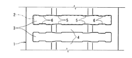
上記柱部4の軸方向中間部分は、径方向内向きに沈み込むように屈曲されている。この沈んだ軸方向中間部分において軸方向両端部5,5の周方向対向間隔、つまりポケット3における内径側の開口幅は、ころ2の直径よりも小さく設定されており、これにより、図4に示すように、ころ2が径方向内向きに抜け出すことを防止するようになっている。また、柱部4において軸方向両端部の周方向両側面には、凸部6が設けられている。ポケット3内に臨む2つの柱部4の各凸部6,6の周方向対向間隔が、ころ2の直径よりも小さく設定されており、これにより、図5に示すように、ころ2が径方向外向きに抜け出すことを防止するようになっている。なお、図4および図5において、PCDは、ころ2および保持器1を使用対象に組み込んだ状態において、すべてのころ2の中心を結ぶ円径を示している。
【0014】
上記構成において、本実施形態では、上記保持器1において、表面の金属組織をマルテンサイトとするとともに、表面の硬度をビッカース硬さ(HV)で400以上700以下、好ましくは400以上600以下、より好ましくは470以上570以下に設定したうえで、内部の金属組織を低炭素マルテンサイトを主体とした組織にするとともに、内部の硬度をビッカース硬さ(HV)で250以上400以下、好ましくは300以上400以下に設定している。
【0015】
要するに、上記数値範囲は、保持器1の表面硬度を過剰に硬くせずに内部硬度を前記表面硬度に近づけることにより、成形や溶接のしやすさを確保したうえで疲労強度を高めることを考慮して、本発明者が実験に基づいて定めたものである。特に、表面の硬度は400HV以上600HV以下であれば疲労強度が向上するが、470HV以上570HV以下が好適である。一方、表面の硬度を上限の700HVとした場合には、疲労強度が若干落ちるものの、耐摩耗性において優れている。これらのことから、要求される条件を考慮して、硬度を設定するのが好ましい。
【0016】
また、保持器1の内部の金属組織が低炭素マルテンサイトを主体とするという意味は、この保持器1の内部にフェライトが例えば10%以下存在する場合も含む意味である。また、上記保持器1の表面とは、特に限定されるものではないが、本発明の一適用例として、例えば、保持器1の板厚を1.2〜2.0mmとした場合において外表面から深さ0.15mmまでの範囲を含むものであり、この範囲に従うとそれよりも深い部分が保持器1の内部となる。
【0017】
このような保持器1の製造方法について説明する。
【0018】
まず、保持器1のベースとなる帯状金属板として、C成分の含有量が0.10%以上0.20%以下に設定された冷間圧延鋼板を用いる。この冷間圧延鋼板としては、例えばBAS規格SPB2(C成分の含有量0.13%以上0.20%以下)を挙げることができる。
【0019】
この帯状金属板に対して、図2に示す断面形状を得るために幅方向中間部分を段付き形状とするよう屈曲する工程と、ポケット3を形成する工程と、熱処理を行う工程と、円筒形に丸めて両端を溶接する工程とを少なくとも行う。なお、溶接工程の後で、例えば研磨仕上げなどを行う。
【0020】
上記熱処理は、浸炭焼入れ、焼き戻しを含む。浸炭焼入れでは、表面に所定量のC成分を浸透拡散させることにより高炭素とし、これを焼入れする。この浸炭時の焼入れでは、例えば、800℃以上900℃以下の温度で、0.5h以上1.0h以下の時間をかけて行う。また、焼き戻しでは、前記浸炭焼入れにより保持器1の表面や内部に残留するオーステナイトをマルテンサイト化させる。この焼き戻しとしては、例えば、300℃以上400℃以下の温度で、0.5h以上1.5h以下の時間をかけて行う。
【0021】
以上説明したように、この実施形態では、保持器1のベースとなる帯状金属板として、従来品よりもC成分の含有量の多い高炭素鋼を用い、熱処理を施すことにより、完成品の保持器1における表面から内部までの金属組織や硬度を上述したように設定している。特に、保持器1の内部の金属組織を、従来例のようなフェライト/パーライトに比べて緻密で安定したものにするとともに、保持器1の内部の硬度を必要十分に高めるようにしている。これにより、保持器1の疲労強度を向上できて、耐久性、信頼性の向上に貢献できるようになる。
【0022】
参考までに、表面硬度を変えて疲労強度試験を行ったので、説明する。試料としては、実施例1,2と比較例との3つを用意した。実施例1,2および比較例に係る試料は、上述した形状の保持器とし、硬度を変えている。実施例1は、素材をJIS規格SPB2として、表面硬度を530HVに、内部硬度は350HVに設定している。実施例2は、素材をJIS規格SPB2として、表面硬度を700HVに、内部硬度は380HVに設定している。比較例は、素材をJIS規格SPCとして、表面硬度を650HVに、内部硬度は150HVに設定している。
【0023】
結果としては、図6に示すように、実施例1,2は、すべての条件において疲労強度が比較例よりも向上していることが確認できた。図6において、縦軸は試料に加えるラジアル方向の荷重を表し、また、横軸は試料に与える荷重の繰り返し数を対数で表している。繰り返し周期は20HZである。
【0024】
なお、本発明は、上記実施形態で例示した保持器1のみに限定されるものではなく、ポケット3の孔形状や柱部4の断面形状が異なるものにも本発明を適用できる。
【0025】
【発明の効果】
本発明のころ軸受用保持器は、従来例に比べて疲労強度が向上するので、条件の厳しい環境での使用においても耐久性ならびに信頼性が向上する。
【図面の簡単な説明】
【図1】本発明の一実施形態に係るころ軸受用保持器の一部を示す斜視図
【図2】図1のころ軸受用保持器の上半分を示す断面図
【図3】図1のころ軸受用保持器のポケットを示す平面展開図
【図4】図1の(4)−(4)線断面の矢視図
【図5】図1の(5)−(5)線断面の矢視図
【図6】本発明ならびに比較例のころ軸受用保持器に関する疲労強度を調べた結果を示す図表
【符号の説明】
1 保持器
2 ころ
3 保持器のポケット
4 保持器の柱部[0001]
BACKGROUND OF THE INVENTION
The present invention relates to a roller bearing retainer and a method for manufacturing a roller bearing retainer .
[0002]
[Prior art]
Among the cages used in roller bearings (so-called cage-and-rollers) composed only of cages, there are welding type cages.
[0003]
This welding type cage is generally formed by performing necessary processing such as forming a pocket using a band-shaped metal plate as a base, and then rounding it into a cylindrical shape to weld both ends.
[0004]
In this welding type cage, for example, low carbon steel such as JIS standard SPC is used for easy forming and welding, and carburizing hardening treatment is applied to the surface portion in order to improve wear resistance. By doing so, the surface metallographic structure is made martensite and the surface is made to have high hardness. (See Patent Document 1).
[0005]
[Patent Document 1]
JP-A-10-237620 [0006]
[Problems to be solved by the invention]
It is pointed out that the cage of the conventional example has insufficient fatigue strength, and the durability is deteriorated particularly when used in a severe environment. In the conventional cage, the surface hardness is 750 to 800 in terms of Vickers hardness (HV), and the internal hardness is 150 to 170 in terms of Vickers hardness (HV). Based on this, the inventor inferred that the metal structure inside the cage of the conventional example is ferrite / pearlite, and as a result of such metal structure, the fatigue strength is insufficient as described above. I thought.
[0007]
[Means for Solving the Problems]
A roller bearing retainer according to the present invention is a roller bearing retainer which is manufactured by rolling a belt-shaped metal plate into a cylindrical shape and welding both ends, and is provided with pockets penetrating radially at several circumferential positions. As the band-shaped metal plate, a cold-rolled steel plate in which the content of the C component is set to 0.10% or more and 0.20% or less is used, and heat treatment is performed on this in the manufacturing process. The surface metal structure is martensite, the surface hardness is set to 400 to 700 in terms of Vickers hardness (HV), and the internal metal structure is mainly composed of low carbon martensite. In addition, the internal hardness is set to 250 or more in terms of Vickers hardness (HV), and the welding is performed on the strip metal plate after the heat treatment.
The method for manufacturing a roller bearing retainer according to the present invention includes a step-shaped intermediate portion in the width direction of a strip-shaped cold-rolled steel sheet in which the C component content is set to 0.10 or more and 0.20% or less. A step of forming a pocket, a step of performing a heat treatment, a step of rounding into a cylindrical shape and welding both ends after the heat treatment, and the heat treatment is performed at 800 ° C. or higher and 900 ° C. or lower. Carburizing and quenching performed at a temperature of 0.5 h to 1.0 h and tempering performed at a temperature of 300 ° C. to 400 ° C. for 0.5 h to 1.5 h. Therefore, the surface metal structure is martensite, the surface hardness is set to 400 to 700 in terms of Vickers hardness (HV), and the internal metal structure is mainly composed of low carbon martensite. Has been Both internal hardness is set to 250 or more Vickers hardness (HV).
[0008]
In this case, since the internal hardness is increased sufficiently and sufficiently after the internal metallographic structure is made dense and stable in the cage, the fatigue strength is improved.
[0009]
Note that a cold-rolled steel sheet in which the content of the C component is set to 0.10% or more and 0.20% or less is used as the band-shaped metal sheet, and heat treatment is performed on this in the manufacturing process. Thus, the metal structure and hardness from the surface to the inside can be ensured. In this case, the metal structure and hardness as described above can be easily ensured.
[0010]
DETAILED DESCRIPTION OF THE INVENTION
1 to 6 show an embodiment of the present invention. In the figure, 1 is a cage and 2 is a roller. This
[0011]
The
[0012]
The
[0013]
The intermediate portion in the axial direction of the
[0014]
In the above configuration, in this embodiment, in the
[0015]
In short, the above numerical range takes into consideration increasing the fatigue strength while ensuring ease of forming and welding by making the internal hardness close to the surface hardness without excessively hardening the surface hardness of the
[0016]
Moreover, the meaning that the metal structure inside the
[0017]
A method for manufacturing such a
[0018]
First, a cold-rolled steel sheet in which the content of the C component is set to 0.10% or more and 0.20% or less is used as the band-shaped metal plate serving as the base of the
[0019]
In order to obtain the cross-sectional shape shown in FIG. 2 with respect to the strip-shaped metal plate, a step of bending the intermediate portion in the width direction to have a stepped shape, a step of forming
[0020]
The heat treatment includes carburizing and quenching and tempering. In carburizing and quenching, a predetermined amount of C component is permeated and diffused on the surface to form high carbon, which is quenched. The quenching at the time of carburization is performed at a temperature of 800 ° C. or higher and 900 ° C. or lower and taking a time of 0.5 h or longer and 1.0 h or shorter. In tempering, the austenite remaining on the surface and inside of the
[0021]
As described above, in this embodiment, a high-carbon steel having a C component content higher than that of the conventional product is used as the band-shaped metal plate serving as the base of the
[0022]
For reference, the fatigue strength test was performed with the surface hardness changed, which will be described. Three samples, Examples 1 and 2 and a comparative example, were prepared as samples. The samples according to Examples 1 and 2 and the comparative example are cages having the shapes described above, and the hardness is changed. In Example 1, the material is JIS standard SPB2, the surface hardness is set to 530 HV, and the internal hardness is set to 350 HV. In Example 2, the material is JIS standard SPB2, the surface hardness is set to 700 HV, and the internal hardness is set to 380 HV. In the comparative example, the material is JIS standard SPC, the surface hardness is set to 650 HV, and the internal hardness is set to 150 HV.
[0023]
As a result, as shown in FIG. 6, Examples 1 and 2 confirmed that the fatigue strength was improved over the comparative example under all conditions. In FIG. 6, the vertical axis represents the radial load applied to the sample, and the horizontal axis represents the logarithm of the number of repetitions of the load applied to the sample. The repetition period is 20HZ.
[0024]
In addition, this invention is not limited only to the holder |
[0025]
【The invention's effect】
The cage for roller bearings of the present invention has improved fatigue strength as compared with the conventional example, so that durability and reliability are improved even in use in severe environments.
[Brief description of the drawings]
FIG. 1 is a perspective view showing a part of a roller bearing retainer according to an embodiment of the present invention. FIG. 2 is a cross-sectional view showing an upper half of the roller bearing retainer shown in FIG. FIG. 4 is a developed plan view showing a pocket of a roller bearing cage. FIG. 4 is a sectional view taken along line (4)-(4) in FIG. 1. FIG. 5 is an arrow taken along line (5)-(5) in FIG. FIG. 6 is a chart showing the results of examining the fatigue strength of the roller bearing cage of the present invention and comparative examples.
1
Claims (2)
前記帯状金属板として、C成分の含有量が0.10%以上0.20%以下に設定された冷間圧延鋼板が用いられており、これに対して製造過程で熱処理が施されることによって表面の金属組織がマルテンサイトとされているとともに、表面の硬度がビッカース硬さ(HV)で400以上700以下に設定されており、かつ、内部の金属組織が低炭素マルテンサイトを主体とされているとともに、内部の硬度がビッカース硬さ(HV)で250以上に設定され、前記熱処理後に前記溶接が前記帯状金属板に対して行われている、ころ軸受用保持器。A roller bearing retainer that is manufactured by rounding a belt-shaped metal plate into a cylindrical shape and welding both ends, and provided with pockets that penetrate in a radial direction at several places on the circumference,
As the strip-shaped metal plate, a cold-rolled steel plate in which the content of C component is set to 0.10% or more and 0.20% or less is used, and heat treatment is performed on this in the manufacturing process. The surface metal structure is martensite, the surface hardness is set to 400 to 700 in terms of Vickers hardness (HV), and the internal metal structure is mainly composed of low carbon martensite. A roller bearing cage in which the internal hardness is set to 250 or more in terms of Vickers hardness (HV), and the welding is performed on the band-shaped metal plate after the heat treatment .
幅方向中間部分を段付き形状とするよう屈曲する工程と、Bending the widthwise intermediate portion to have a stepped shape;
ポケットを形成する工程と、Forming a pocket;
熱処理を行う工程と、A step of performing a heat treatment;
熱処理後に円筒形に丸めて両端を溶接する工程とを含んでおり、A step of rounding into a cylindrical shape after heat treatment and welding both ends,
上記熱処理は、800℃以上900℃以下の温度で0.5h以上1.0h以下の時間をかけて行う浸炭焼入れと、The above heat treatment is carburizing and quenching performed at a temperature of 800 ° C. or more and 900 ° C. or less over a period of 0.5 h or more and 1.0 h or less,
300℃以上400℃以下の温度で、0.5h以上1.5以下の時間をかけて行う焼き戻しとを含むことにより、Including tempering performed at a temperature of 300 ° C. or more and 400 ° C. or less at a temperature of 0.5 h or more and 1.5 or less,
表面の金属組織がマルテンサイトとされているとともに、表面の硬度がビッカース硬さ(HV)で400以上700以下に設定されており、かつ、内部の金属組織が低炭素マルテンサイトを主体とされているとともに、内部の硬度がビッカース硬さ(HV)で250以上に設定された、ころ軸受用保持器の製造方法。The surface metal structure is martensite, the surface hardness is set to 400 to 700 in terms of Vickers hardness (HV), and the internal metal structure is mainly composed of low carbon martensite. And a method for manufacturing a roller bearing retainer in which the internal hardness is set to 250 or more in terms of Vickers hardness (HV).
Priority Applications (1)
| Application Number | Priority Date | Filing Date | Title |
|---|---|---|---|
| JP2003007837A JP4120406B2 (en) | 2003-01-16 | 2003-01-16 | Roller bearing cage and method for manufacturing roller bearing cage |
Applications Claiming Priority (1)
| Application Number | Priority Date | Filing Date | Title |
|---|---|---|---|
| JP2003007837A JP4120406B2 (en) | 2003-01-16 | 2003-01-16 | Roller bearing cage and method for manufacturing roller bearing cage |
Publications (2)
| Publication Number | Publication Date |
|---|---|
| JP2004218761A JP2004218761A (en) | 2004-08-05 |
| JP4120406B2 true JP4120406B2 (en) | 2008-07-16 |
Family
ID=32897814
Family Applications (1)
| Application Number | Title | Priority Date | Filing Date |
|---|---|---|---|
| JP2003007837A Expired - Fee Related JP4120406B2 (en) | 2003-01-16 | 2003-01-16 | Roller bearing cage and method for manufacturing roller bearing cage |
Country Status (1)
| Country | Link |
|---|---|
| JP (1) | JP4120406B2 (en) |
Families Citing this family (2)
| Publication number | Priority date | Publication date | Assignee | Title |
|---|---|---|---|---|
| JP2007263220A (en) * | 2006-03-28 | 2007-10-11 | Nsk Ltd | Cage and roller |
| US8602657B2 (en) * | 2009-06-15 | 2013-12-10 | Koyo Bearings Usa Llc | Cage for bearing assembly |
-
2003
- 2003-01-16 JP JP2003007837A patent/JP4120406B2/en not_active Expired - Fee Related
Also Published As
| Publication number | Publication date |
|---|---|
| JP2004218761A (en) | 2004-08-05 |
Similar Documents
| Publication | Publication Date | Title |
|---|---|---|
| US8166657B2 (en) | Needle roller bearing | |
| JP2013164093A (en) | Manufacturing method of race for thrust needle bearing | |
| JP4810157B2 (en) | Rolling bearing | |
| JP5168958B2 (en) | Rolling shaft | |
| JP3073937B2 (en) | Manufacturing method of shell type needle roller bearing | |
| EP1418354B1 (en) | Thrust roller bearing and cage | |
| JP3212880B2 (en) | Shell type needle roller bearing | |
| JP5612912B2 (en) | Deep groove ball bearing | |
| JP5598016B2 (en) | Manufacturing method of thrust trace of needle thrust bearing | |
| JP4120406B2 (en) | Roller bearing cage and method for manufacturing roller bearing cage | |
| JP5070735B2 (en) | Rolling bearing | |
| WO2022202922A1 (en) | Track wheel and shaft | |
| JP2020079630A (en) | Cage for constant velocity universal joint, and constant velocity universal joint | |
| JP2013164095A (en) | Race for thrust needle bearing | |
| JP2004156738A (en) | Thrust roller bearing | |
| JP6843786B2 (en) | Manufacturing method of bearing parts, rolling bearings, and bearing parts | |
| JP3923862B2 (en) | Thrust needle roller bearing | |
| JP2009092161A (en) | Rolling bearing | |
| JP3905432B2 (en) | Thrust needle roller bearing and manufacturing method thereof | |
| JP2005299775A (en) | Rolling bearing | |
| JP2009236227A (en) | Method of manufacturing for rolling bearing retainer | |
| JP3936250B2 (en) | Thrust needle roller bearing | |
| JP2004156723A (en) | Thrust roller bearing and retainer | |
| JP2024016666A (en) | tapered roller bearing | |
| JP2024034788A (en) | Drawn cup needle roller bearing |
Legal Events
| Date | Code | Title | Description |
|---|---|---|---|
| A621 | Written request for application examination |
Free format text: JAPANESE INTERMEDIATE CODE: A621 Effective date: 20050823 |
|
| A977 | Report on retrieval |
Free format text: JAPANESE INTERMEDIATE CODE: A971007 Effective date: 20070618 |
|
| A131 | Notification of reasons for refusal |
Free format text: JAPANESE INTERMEDIATE CODE: A131 Effective date: 20070703 |
|
| A521 | Written amendment |
Free format text: JAPANESE INTERMEDIATE CODE: A523 Effective date: 20070903 |
|
| TRDD | Decision of grant or rejection written | ||
| A01 | Written decision to grant a patent or to grant a registration (utility model) |
Free format text: JAPANESE INTERMEDIATE CODE: A01 Effective date: 20080401 |
|
| A61 | First payment of annual fees (during grant procedure) |
Free format text: JAPANESE INTERMEDIATE CODE: A61 Effective date: 20080414 |
|
| FPAY | Renewal fee payment (event date is renewal date of database) |
Free format text: PAYMENT UNTIL: 20110509 Year of fee payment: 3 |
|
| R150 | Certificate of patent or registration of utility model |
Free format text: JAPANESE INTERMEDIATE CODE: R150 |
|
| FPAY | Renewal fee payment (event date is renewal date of database) |
Free format text: PAYMENT UNTIL: 20110509 Year of fee payment: 3 |
|
| FPAY | Renewal fee payment (event date is renewal date of database) |
Free format text: PAYMENT UNTIL: 20120509 Year of fee payment: 4 |
|
| FPAY | Renewal fee payment (event date is renewal date of database) |
Free format text: PAYMENT UNTIL: 20120509 Year of fee payment: 4 |
|
| FPAY | Renewal fee payment (event date is renewal date of database) |
Free format text: PAYMENT UNTIL: 20130509 Year of fee payment: 5 |
|
| FPAY | Renewal fee payment (event date is renewal date of database) |
Free format text: PAYMENT UNTIL: 20140509 Year of fee payment: 6 |
|
| LAPS | Cancellation because of no payment of annual fees |