JP2005299775A - Rolling bearing - Google Patents
Rolling bearing Download PDFInfo
- Publication number
- JP2005299775A JP2005299775A JP2004115573A JP2004115573A JP2005299775A JP 2005299775 A JP2005299775 A JP 2005299775A JP 2004115573 A JP2004115573 A JP 2004115573A JP 2004115573 A JP2004115573 A JP 2004115573A JP 2005299775 A JP2005299775 A JP 2005299775A
- Authority
- JP
- Japan
- Prior art keywords
- nitriding
- cage
- thickness
- rolling bearing
- bent
- Prior art date
- Legal status (The legal status is an assumption and is not a legal conclusion. Google has not performed a legal analysis and makes no representation as to the accuracy of the status listed.)
- Pending
Links
Images

Landscapes
- Rolling Contact Bearings (AREA)
- Heat Treatment Of Articles (AREA)
Abstract
【課題】 形状を考慮して溶融塩を用いた窒化処理よりも均質な窒化層厚さを提供することにより使用条件の選定に適した転がり軸受を提供すること。
【解決手段】 転動体11と、転動体11を転動自在に保持する保持器12と、を備え、保持器12が、折り曲げ加工された折り曲げ部17,18,21,22を有し、折り曲げ部17,18,21,22に、折り曲げ部半径/板厚の比率が0.7以下となる塑性加工部23,24,25,26を成形し、塑性加工部23,24,25,26の窒化層が、内側厚さ/外側厚さの比率を0.8以上に設定された転がり軸受10。
【選択図】 図1PROBLEM TO BE SOLVED: To provide a rolling bearing suitable for selection of use conditions by providing a nitride layer thickness that is more uniform than nitriding treatment using molten salt in consideration of the shape.
SOLUTION: A rolling element 11 and a holder 12 that holds the rolling element 11 so as to be freely rollable. The holder 12 has bent portions 17, 18, 21, and 22 that are bent and bent. Plastic parts 23, 24, 25, and 26 having a bent portion radius / plate thickness ratio of 0.7 or less are formed on the parts 17, 18, 21, and 22, and the plastic parts 23, 24, 25, and 26 are formed. The rolling bearing 10 in which the nitride layer has a ratio of inner thickness / outer thickness set to 0.8 or more.
[Selection] Figure 1
Description
本発明は、自動車、一般産業機械、工作機械、鉄鋼機械、等に用いられる転がり軸受に関し、特に、プレス成形された保持器を備えた転がり軸受に関する。 The present invention relates to a rolling bearing used for automobiles, general industrial machines, machine tools, steel machines, and the like, and more particularly, to a rolling bearing provided with a press-molded cage.
転がり軸受のうち、ニードル軸受に組み込まれる保持器は、転動体である針状ころに対して滑り接触するため、耐摩耗性、耐焼付き性を満足する必要がある。また、ニードル軸受の回転時に保持器が引張や圧縮の繰返し応力を受ける場合がある。ニードル軸受に大きな負荷が作用する場合、強度に優れる高力黄銅製のもみ抜き保持器が使用されている。高力黄銅は自己潤滑性を有し摺動性、耐摩耗性に優れるが、材料コストが高く、また、もみ抜きで加工されるために、加工費が高く、材料歩留まりも低くなってしまい、特殊用途に限定されている。 Of the rolling bearings, the cage incorporated in the needle bearing is in sliding contact with the needle roller that is a rolling element, and therefore needs to satisfy wear resistance and seizure resistance. In addition, the cage may be subjected to repeated tensile or compressive stress when the needle bearing rotates. When a large load is applied to the needle bearing, a high-strength brass machined cage that has excellent strength is used. High-strength brass has self-lubricating properties and is excellent in slidability and wear resistance, but the material cost is high, and because it is processed with chopping, the processing cost is high and the material yield is low, Limited to special applications.
近年、SPCCに代表される冷間圧延用鋼板あるいはSPHDに代表される熱間圧延鋼板製の鋼製のプレス成形された保持器は材料費も安く、プレス成形性も良いので、量産性に優れ、コストが安価であるという利点を有して使用されているが、強度、耐摩耗性、耐焼付き性を向上する必要がある。例えば、ニードル軸受に振動や衝撃荷重が作用するような場合は、保持器の破損が問題になり、また、潤滑油の供給が少ない場合には、ポケット部分が摩耗してしまうという問題がある。このような課題を解決するため、例えば、SPCCからなる保持器の表面に、塩浴窒化、ガス窒化及び塩浴窒化の窒化処理を含む表面硬化処理を施して強度の向上と耐摩耗性の向上を図るようにしたものが提案されている。 In recent years, cold-rolled steel plates typified by SPCC or hot-rolled steel plates typified by SPHD have low material costs and good press formability, so they are excellent in mass productivity. Although it is used with the advantage that the cost is low, it is necessary to improve the strength, wear resistance, and seizure resistance. For example, when a vibration or impact load is applied to the needle bearing, there is a problem that the cage is broken, and when the supply of lubricating oil is small, the pocket portion is worn. In order to solve such problems, for example, the surface of a cage made of SPCC is subjected to surface hardening treatment including salt bath nitriding, gas nitriding and nitriding treatment of salt bath nitriding to improve strength and wear resistance. There are proposals to make this possible.
そこで、保持器の表面の酸化物を、金属フッ化膜に置き換えるフッ化処理をした後処理を施した転がり軸受が提案されている(例えば、特許文献1参照)。
ところで、近年、保持器の高機能化が進み、単にプレス板の打ち抜きではなく、案内機能や針状ころの姿勢制御の機能を持たせるために、プレス保持器が複雑形状化している。
そして、上記の特許文献1では、プレス加工が特に厳しい場所に、窒化が不十分な場所が存在する。特に、保持器に折り曲げ加工部があり、折り曲げ部内面側の曲率が小さくなると、塩浴が十分に行き渡らなくなって窒化されにくい傾向がある。その場合、回転条件によって保持器の特定部位に過大な繰返し応力が負与されると、窒化層の薄くなった部分が破壊の起点となってしまう虞がある。
By the way, in recent years, the function of the retainer has been improved, and the press retainer has a complicated shape in order to provide not only the punching of the press plate but also the function of guiding and controlling the posture of the needle rollers.
And in said
本発明はこのような問題を改善するためになされたものであり、その目的は、形状を考慮して溶融塩を用いた窒化処理よりも均質な窒化層厚さを提供することにより使用条件の選定に適した転がり軸受を提供することにある。 The present invention has been made to remedy such problems. The purpose of the present invention is to provide a nitride layer thickness that is more uniform than the nitridation treatment using molten salt in consideration of the shape. It is to provide a rolling bearing suitable for selection.
本発明の上記目的は、以下の構成により達成される。
1)本発明に係る転がり軸受は、軌道面を転動する複数の転動体と、前記転動体を転動自在に保持する保持器と、を備えた転がり軸受であって、前記保持器が、折り曲げ加工された折り曲げ部を有し、前記折り曲げ部に、折り曲げ部半径/板厚の比率が0.7以下となる塑性加工部が成形され、前記塑性加工部の窒化層が、内側厚さ/外側厚さの比率を0.8以上に設定されていることを特徴とする。
前記構成の転がり軸受によれば、折り曲げ部半径/板厚の比率が0.7以下となる塑性加工部を有する鋼製の保持器に塩浴窒化を施す場合、折り曲げ部の内側と外側とで窒化層の厚さが異なるものとなり、保持器の強度にばらつきが生ずる。これに対して、塑性加工部の窒化層が、内側厚さ/外側厚さの比率を0.8以上に設定されることにより、均一な強度をもつ保持器を得ることができる。
The above object of the present invention is achieved by the following configurations.
1) A rolling bearing according to the present invention is a rolling bearing comprising a plurality of rolling elements that roll on a raceway surface, and a cage that holds the rolling elements in a freely rolling manner, wherein the cage is A bent portion formed by bending, and a plastic processed portion having a ratio of a bent portion radius / plate thickness of 0.7 or less is formed in the bent portion, and a nitride layer of the plastic processed portion has an inner thickness / The ratio of the outer thickness is set to 0.8 or more.
According to the rolling bearing having the above-described configuration, when salt bath nitriding is performed on a steel cage having a plastic working portion in which the ratio of the bending portion radius / plate thickness is 0.7 or less, the inner side and the outer side of the bending portion The thickness of the nitride layer differs, and the strength of the cage varies. On the other hand, the nitride layer of the plastic working portion has a ratio of inner thickness / outer thickness set to 0.8 or more, whereby a cage having uniform strength can be obtained.
2)本発明に係る転がり軸受は、前記1)に記載の転がり軸受であって、前記保持器は、窒化処理がガスを窒化媒体とした方法により処理されたこと特徴とする。
前記構成の転がり軸受によれば、ガスを窒化媒体とした窒化処理を行うことにより、塩浴窒化と比較して流動性が良好になるために、窒化反応が緩慢になり難く、保持器全体の窒化層を均一にして強度を向上することができる。
2) A rolling bearing according to the present invention is the rolling bearing described in 1) above, wherein the cage is characterized in that the nitriding treatment is performed by a method using a gas as a nitriding medium.
According to the rolling bearing having the above-described configuration, by performing nitriding treatment using a gas as a nitriding medium, fluidity is improved as compared with salt bath nitriding. The strength can be improved by making the nitride layer uniform.
ここで、上記目的を達成するために、本発明者は鋭意研究を重ね、窒化むらの発生と保持器形状の関係を明らかにし、更に窒化むらの発生しやすい形状については窒化方法を変えることで均一な窒化層で得られるという知見を得た。具体的には、折り曲げ部半径/板厚の比率が0.7以下である保持器において、窒化むらの発生しやすい折り曲げ部の内側に着目し、塑性加工部の、内側厚さ/外側厚さの比率が0.8以上にする窒化方法として、塩浴窒化でなくガス軟窒化に代表されるガス系窒化を適用し、保持器の強度を向上させることを可能とした。 Here, in order to achieve the above-mentioned object, the present inventor has conducted intensive research and clarified the relationship between the occurrence of uneven nitriding and the shape of the cage. The knowledge that a uniform nitrided layer can be obtained was obtained. Specifically, in a cage having a bent portion radius / plate thickness ratio of 0.7 or less, focusing on the inside of the bent portion where uneven nitriding is likely to occur, the inner thickness / outer thickness of the plastic working portion As a nitriding method for making the ratio of 0.8 or more, gas-based nitriding typified by gas soft nitriding instead of salt bath nitriding was applied, and the strength of the cage could be improved.
本発明の転がり軸受によれば、形状を考慮して溶融塩を用いた窒化処理よりも均質な窒化層厚さを提供することにより使用条件の選定に適した転がり軸受を得ることができる。 According to the rolling bearing of the present invention, it is possible to obtain a rolling bearing suitable for selection of use conditions by providing a more uniform nitrided layer thickness than the nitriding treatment using molten salt in consideration of the shape.
以下、本発明の実施形態に係る転がり軸受を図面に基づいて詳細に説明する。 Hereinafter, a rolling bearing according to an embodiment of the present invention will be described in detail with reference to the drawings.
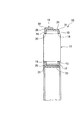
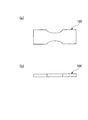
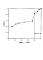
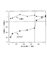
図1は本発明に係る一実施形態の転がり軸受の断面図、図2(a)は実施例に用いた試験片の平面図、図2(b)は図2(a)の正面図、図3はタフトライド処理の条件表、図4は実施例で行った疲労試験の結果を示すグラフ、図5は(折り曲げ部半径)/(板厚)と(内側厚さ)/(外側厚さ)との関係を調べたグラフ、図6(a)は実施例で行った試験用保持器の平面図、図6(b)は実施例で行った疲労試験の模式図、図7は実施例の結果表である。 1 is a cross-sectional view of a rolling bearing according to an embodiment of the present invention, FIG. 2A is a plan view of a test piece used in the example, FIG. 2B is a front view of FIG. 3 is a table showing the conditions of the tuftride treatment, FIG. 4 is a graph showing the results of the fatigue test conducted in the examples, and FIG. 5 is (folded portion radius) / (plate thickness) / (inner thickness) / (outer thickness). FIG. 6A is a plan view of the test cage performed in the example, FIG. 6B is a schematic diagram of the fatigue test performed in the example, and FIG. 7 is the result of the example. It is a table.
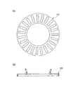
図1に示すように、本発明の一実施形態である転がり軸受10は、軌道面を転動する複数の転動体である針状ころ11と、針状ころ11を転動自在に保持する保持器12と、から構成されている。
As shown in FIG. 1, a
針状ころ11は、例えば、オートマチックトランスミッションのパワートレン内やトルクコンバータ内における、回転部分と非回転部分との間、または、回転部分と回転部分との間に挟まれて、それらの軌道面に対して相対的に回転する。
The
保持器12は、スラストケージとも呼ばれ、鋼板をプレス加工することにより全体が円環形状に形成され、それぞれ端部断面がコ字形状に形成された第1,第2保持器部材13,14を組み合わせてなる。
The
第1保持器部材13は、円環板形状に形成された本体15に、長方形形状の第1保持器部材側ポケット16が放射状にして円周方向に複数形成されている。そして、本体15の内周縁部に内周側折り曲げ部17が形成され、本体15の外周縁部に外周側折り曲げ部18が形成されている。
The
第2保持器部材14は、第1保持器部材13と同様にして、円板形状に形成された本体19に、長方形形状の第2保持器部材側ポケット20が放射状にして円周方向に複数形成されている。そして、本体19の内周縁部に内周側折り曲げ部21が形成され、本体19の外周縁部に外周側折り曲げ部22が形成されている。
Similarly to the
保持器12は、第1,第2保持器部材側ポケット16,20によって針状ころ11を挟み込むようにして、第1保持器部材13を第2保持器部材14のコ字形状の開口の内側に嵌め込むことにより、第1,第2保持器部材13,14が一体的に組み付けられて、針状ころ11を転動自在に保持する。
The
そして、第1保持器部材13における内周側折り曲げ部17に、折り曲げ部17の半径/板厚の比率が0.7以下となる塑性加工部23が形成されており、第1保持器部材13における外周側折り曲げ部18に、折り曲げ部18の半径/板厚の比率が0.7以下となる塑性加工部24が成形されている。
And the
そしてまた、第2保持器部材14における内周側折り曲げ部21に、折り曲げ部21の半径/板厚の比率が0.7以下となる塑性加工部25が形成されており、第2保持器部材14における外周側折り曲げ部22に、折り曲げ部22の半径/板厚の比率が0.7以下となる塑性加工部26が成形されている。
Further, a plastic working
さらに、保持器12は、第1保持器部材13における各塑性加工部23,24の窒化層が、内側厚さ/外側厚さの比率を0.8以上にして成形されており、第2保持器部材14における塑性加工部25,26の窒化層が、内側厚さ/外側厚さの比率を0.8以上にして成形されている。通常、折り曲げ部半径/板厚の比率が0.7以下となる塑性加工部を有する鋼製の保持器に塩浴窒化を施す場合、折り曲げ部の内側と外側とで窒化層の厚さが異なるものとなり、保持器の強度にばらつきが生ずる。これに対して、転がり軸受12では、塑性加工部23,24,25,26の窒化層を、内側厚さ/外側厚さの比率が0.8以上とすることによって、均一な強度をもつ保持器を得ている。
Further, in the
そして、保持器12は、第1保持器部材13における塑性加工部23,24、第2保持器部材14における塑性加工部25,26が、窒化処理にガスを窒化媒体とした方法を用いて処理されている。保持器12が、ガスを窒化媒体とした窒化処理を行うことにより成形されているために、塩浴窒化と比較して流動性が良好になるために、窒化反応が緩慢になり難く、保持器12全体の窒化層が均一にされて強度が向上されている。
In the
ところで、転がり軸受10に使用されるSPCCやSPHD等の低炭素鋼に前処理として、450〜600℃の温度領域で鋼をオーステナイト化させずに、外部から鋼内部へ窒化を拡散させることで、ξ相(Fe2N)、ε相(Fe2〜3N)、γ´相(Fe4N)、からなる窒化鉄が形成される。窒化処理により鋼の表面を硬質にすることができ、強度、耐摩耗性、耐焼付きに大きく影響し、それに伴い材料の寿命に大きく影響を与える。一般的な窒化方法として、日本パーカライジング株式会社のタフトライド処理、ナルソナイト処理の塩浴窒化、同和鉱業株式会社のタフナイト処理、エアー・ウオーター株式会社の商品名Nv超窒化に代表されるガス軟窒化やイオン窒化があげられる。 By the way, as a pretreatment to low carbon steel such as SPCC and SPHD used for the rolling bearing 10, by nitriding from outside to inside the steel without austenitizing the steel in a temperature range of 450 to 600 ° C., Iron nitride composed of ξ phase (Fe 2 N), ε phase (Fe 2-3 N), and γ ′ phase (Fe 4 N) is formed. Nitriding can harden the surface of the steel, greatly affecting strength, wear resistance, and seizure resistance and, accordingly, greatly affecting the life of the material. Common nitriding methods include tuftride treatment by Nippon Parkerizing Co., Ltd., salt bath nitridation by narsonite treatment, toughnite treatment by Dowa Mining Co., Ltd. Nitriding is an example.
プレス加工によって折り曲げ部を形成した保持器12にタフトライドやパルソナイト等の塩浴窒化処理を施した場合、折り曲げ部の内側と外側とで窒化層の厚さに違いが生じる場合がある。保持器の製造手順は、鋼製の板に塑性加工を加えることで保持器形状にし、その後に窒化処理を施すため、溶融塩を用いた窒化の場合、折り曲げ部の内側では溶融塩の流動が不良になってしまう傾向にある。そのため、反応時間の経過とともに折り曲げ部の内側では反応に関与する窒素の供給が不十分となり、窒化反応が緩慢になる。そこで、折り曲げ部の内側において窒化反応を緩慢にしない手段が不可欠である。ガスを媒体とした窒化は塩浴窒化と比較して流動性が良いため、窒化反応が緩慢になり難く、保持器全体の窒化層が均一なものになる。
When the
窒化をした場合の強度や疲労強度は、窒化層の厚さが厚いほど高くなることが知られている。従って、保持器の窒化処理において窒化層厚さが部位により不均一になってしまう場合、その箇所において応力集中が負荷される条件下では窒化層の薄い部分が材料破壊の起点となってしまう場合がある。このため、保持器12全体の窒化むらをなくすことが材料強度に非常に重要である。
It is known that the strength and fatigue strength when nitriding is increased as the thickness of the nitrided layer is increased. Therefore, when the nitrided layer thickness becomes uneven depending on the part in the nitriding treatment of the cage, the thin part of the nitrided layer becomes the starting point of material destruction under the condition that stress concentration is applied at that part. There is. For this reason, it is very important for material strength to eliminate uneven nitriding of the
転がり軸受10によれば、保持器12が、第1保持器部材13に内周側,外周側折り曲げ部17,18を有し、内周側,外周側折り曲げ部17,18に、 折り曲げ部半径/板厚の比率が0.7以下となる塑性加工部23,24が成形されているとともに、第2保持器部材14に内周側,外周側折り曲げ部21,22を有し、内周側,外周側折り曲げ部21,22に、折り曲げ部半径/板厚の比率が0.7以下となる塑性加工部25,26が成形されており、各塑性加工部23,24,25,26の窒化層が、内側厚さ/外側厚さの比率を0.8以上に設定されていることにより、均一な強度をもつ保持器12を得ることができる。
According to the rolling
また、転がり軸受10によれば、ガスを窒化媒体とした窒化処理を行うことにより、塩浴窒化と比較して流動性が良好になるために、窒化反応が緩慢になり難く、保持器12全体の窒化層を均一にして強度を向上することができる。
In addition, according to the rolling
(疲労試験1)
本発明の転がり軸受10における保持器12の窒化むらによる強度の影響を調べるために、疲労試験1とする平面曲げ疲労試験を行って評価した。
(Fatigue test 1)
In order to investigate the influence of the strength due to the uneven nitriding of the
図2(a),(b)に示すように、平面曲げ疲労試験には、試験片100を用いた。試験片100は、予め定められた厚さをもつ四角形形状の板部材であり、両側面の中央部に凹部が形成されている。試験片100に対して20Hzの曲げ応力を加え、試験片100にクラックが入るまでの繰り返し数を測定した。繰り返し数1×10⁷サイクルをもって疲労限とし、疲労限の応力を評価した。
As shown in FIGS. 2A and 2B, a
試験片100への窒化処理の手順は以下の通りである。
まず、試験片100の下部にめっきを施した後、図3に示す条件でタフトライド処理を行った。その後、めっきを取り除きサイド窒化処理することにより、上部厚さ/下部厚さをコントロールした。その後、窒化層厚さをSEMにより観察して、上部厚さ/下部厚さを算出した。
The procedure for nitriding the
First, after plating the lower part of the
図4に示すように、疲労試験1の結果は、窒化層厚さと曲げ疲労との関係により明らかになる。この結果からわかるように、(上部厚さ)/(下部厚さ)が、本発明に相当する、0.8〜1.0の範囲では疲労強度に顕著な低下は見られない。一方、(上部厚さ)/(下部厚さ)が0.8未満になると疲労強度が顕著な低下を示していることがわかる。上述した通り、このことは、材料の部位による窒化むらがあると材料強度が低下することを示しており(上部厚さ)/(下部厚さ)が0.8以上でなければ、材料強度に及ぼす窒化の影響が大きいと言える。
As shown in FIG. 4, the result of the
上述したように、窒化むらは、折り曲げ加工の内面で起こりやすいので、窒化と形状との関係を知るために内径部の曲率と板厚に着目した。その後、図3に示した条件で窒化処理を施し、外側半径と内側半径との窒化層厚さをSEM観察し算出した。 As described above, non-uniform nitriding tends to occur on the inner surface of the bending process, so attention was paid to the curvature and plate thickness of the inner diameter portion in order to know the relationship between nitriding and shape. Thereafter, nitriding treatment was performed under the conditions shown in FIG.
図5により明らかなように、(折り曲げ部半径)/(板厚)が0.7以下になると、図中に線Bで示すように、タフトライドの場合、折り曲げ部の(内側厚さ)/(外側厚さ)が低下していることがわかる。一方、本発明に係るNv窒化(ガス軟窒化)の場合は、図中に線Aで示すように、(折り曲げ部)/(板厚)が0.7以下になった場合でも、折り曲げ部の(内側厚さ)/(外側厚さ)に変動はほとんどないことがわかる。この結果からもわかるように、タフトライド処理における窒化むらの発生は形状に依存し、折り曲げ部の内側での塩浴の滞留によって生じると考えられる。これに対し、Nv窒化は形状に依存せず、本発明の0.8以上を保っている。以上の結果から、折り曲げ部の値が0.7以下の厳しい加工部を有する場合、ガスを媒体とした窒化を施し、(内側厚さ)/(外側厚さ)を0.8とすることで強度むらのない、強固な保持器を提供することができる。 As apparent from FIG. 5, when (folded portion radius) / (plate thickness) becomes 0.7 or less, as shown by line B in the figure, in the case of tuftride, (inner thickness) / ( It can be seen that the outer thickness is reduced. On the other hand, in the case of Nv nitriding (gas soft nitriding) according to the present invention, as shown by line A in the figure, even when (folded portion) / (plate thickness) is 0.7 or less, It can be seen that there is almost no variation in (inner thickness) / (outer thickness). As can be seen from this result, the occurrence of uneven nitriding in the tuftride treatment depends on the shape and is considered to be caused by the retention of the salt bath inside the bent portion. On the other hand, Nv nitriding does not depend on the shape and maintains 0.8 or more of the present invention. From the above results, when there is a severely processed portion with a bent portion value of 0.7 or less, nitriding using gas as a medium is performed, and (inner thickness) / (outer thickness) is set to 0.8. A strong cage without unevenness in strength can be provided.
(疲労試験2)
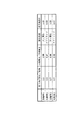
本発明の効果を確認するために、更に、疲労試験2として、以下の実験を行った。加工により(折り曲げ部半径)/(板厚)を変えた4種類のスラストニードル保持器(素材:S10C)に、図3に示した条件で窒化処理を施し、図6に示すように、試験用保持器101の端面(ベクトル部)に20Hzで繰返し応力を加え、疲労試験を行った。疲労試験は、試験用保持器101にクラックが入るまでの繰り返し数を測定し、繰り返し数1×107サイクルを疲労強度として評価した。その後、折り曲げた部分の窒化層厚さをSEM観察により算出した。これらの結果を図7に示す。図7では、Nv窒化処理した保持器の疲労強度を1としてタフトライドのものと比較した。4種類の保持器の仕様は以下の通りである。
実施例1:(折り曲げ部半径(R))/(板厚)の値が0.3、窒化処理の種類:Nv窒化
比較例1:(折り曲げ部半径(R))/(板厚)の値が0.3、窒化処理の種類:タフトライド
実施例2:(折り曲げ部半径(R))/(板厚)の値が0.7、窒化処理の種類:Nv窒化
比較例2:(折り曲げ部半径(R))/(板厚)の値が0.7、窒化処理の種類:タフトライド
(Fatigue test 2)
In order to confirm the effect of the present invention, the following experiment was further conducted as fatigue test 2. Four types of thrust needle holders (material: S10C) whose (folded part radius) / (plate thickness) were changed by processing were subjected to nitriding treatment under the conditions shown in FIG. 3, and as shown in FIG. A fatigue test was performed by repeatedly applying stress to the end face (vector part) of the
Example 1: The value of (folded portion radius (R)) / (plate thickness) is 0.3, the type of nitriding treatment: Nv nitriding Comparative Example 1: the value of (folded portion radius (R)) / (plate thickness) 0.3, type of nitriding treatment: tuftride Example 2: (bending portion radius (R)) / (plate thickness) is 0.7, nitriding type: Nv nitriding Comparative Example 2: (folding portion radius (R)) / (plate thickness) is 0.7, nitriding type: tuftride
図7に示す結果からわかるように、タフトライドで窒化したものは、(内側厚さ)/(外側厚さ)の値が、比較例1では0.47、比較例2では0.65となっていずれも低い値を示しており、それに伴って疲労強度比の値が、比較例1では0.55、比較例2では0.67となっていずれも低い。一方、Nv窒化を施したものは、(内側厚さ)/(外側厚さ)の値が、実施例1では0.99、実施例2では0.98となっていずれも高い値を示しており、それに伴って疲労強度比の値が、実施例1では1.00、実施例2では1.00となっていずれも高い値になった。これにより、Nv窒化を施すことにより、窒化むらがほとんどなく、疲労強度を比較してもタフトライドよりも優れていることがわかる。このような窒化むらを有する材料は保持器としての性能を十分に発揮できず、転がり軸受に組み込んだ直後に窒化層の薄い部分が起点となり保持器が早期に破壊されることが考えられる。尚、上記の各実施例において、ガス窒化の例としてNv窒化を例示したが、ガスを媒体にした窒化であれば種類は問わない。また、実施例ではスラストニードル保持器を例示したが限定されない。 As can be seen from the results shown in FIG. 7, the value of (inner thickness) / (outer thickness) of nitrided with tuftride is 0.47 in Comparative Example 1 and 0.65 in Comparative Example 2. Both show low values, and accordingly, the value of the fatigue strength ratio is 0.55 in Comparative Example 1 and 0.67 in Comparative Example 2, both of which are low. On the other hand, in the case of Nv nitriding, the value of (inner thickness) / (outer thickness) was 0.99 in Example 1 and 0.98 in Example 2, and both showed high values. Accordingly, the value of the fatigue strength ratio was 1.00 in Example 1 and 1.00 in Example 2, both of which were high values. Thus, it can be seen that by performing Nv nitriding, there is almost no uneven nitriding, and even if the fatigue strength is compared, it is superior to tuftride. Such a material having uneven nitriding cannot sufficiently exhibit the performance as a cage, and it is conceivable that the cage is destroyed at an early stage due to a thin portion of the nitride layer as a starting point immediately after being incorporated into a rolling bearing. In each of the above embodiments, Nv nitridation is exemplified as an example of gas nitriding, but any type can be used as long as nitriding using gas as a medium. Moreover, although the thrust needle holder was illustrated in the Example, it is not limited.
なお、本発明は、前述した実施形態に限定されるものではなく、適宜、変形、改良等が可能である。例えば、転がり軸受として、図示したような針状ころと保持器とから構成されるものに代えて、フランジなしの軌道輪が片側に組み付けられたものや、フランジ付きの軌道輪が片側に組み付けられたもの、或いは、これら軌道輪が両側に組み付けられたものに本発明を適用しても良い。 In addition, this invention is not limited to embodiment mentioned above, A deformation | transformation, improvement, etc. are possible suitably. For example, as a rolling bearing, instead of a roller bearing and a cage as shown in the figure, a bearing ring without a flange is assembled on one side, or a bearing ring with a flange is assembled on one side. The present invention may be applied to a structure in which these race rings are assembled on both sides.
10 転がり軸受
11 針状ころ(転動体)
12 保持器
17 内周側折り曲げ部(折り曲げ部)
18 外周側折り曲げ部(折り曲げ部)
21 内周側折り曲げ部(折り曲げ部)
22 外周側折り曲げ部(折り曲げ部)
23 塑性加工部
24 塑性加工部
25 塑性加工部
26 塑性加工部
10
12
18 Bending part on the outer circumference side (bending part)
21 Inner peripheral side bending part (bending part)
22 Bending part on the outer circumference side (bending part)
23
Claims (2)
前記保持器が、折り曲げ加工された折り曲げ部を有し、前記折り曲げ部に、折り曲げ部半径/板厚の比率が0.7以下となる塑性加工部が成形され、前記塑性加工部の窒化層が、内側厚さ/外側厚さの比率を0.8以上に設定されていることを特徴とする転がり軸受。 A rolling bearing comprising a plurality of rolling elements that roll on a raceway surface, and a cage that holds the rolling elements in a freely rolling manner,
The cage has a bent portion that is bent, and a plastic processing portion having a ratio of the bending portion radius / plate thickness of 0.7 or less is formed in the bending portion, and a nitride layer of the plastic processing portion is formed. A rolling bearing characterized in that the ratio of inner thickness / outer thickness is set to 0.8 or more.
Priority Applications (1)
| Application Number | Priority Date | Filing Date | Title |
|---|---|---|---|
| JP2004115573A JP2005299775A (en) | 2004-04-09 | 2004-04-09 | Rolling bearing |
Applications Claiming Priority (1)
| Application Number | Priority Date | Filing Date | Title |
|---|---|---|---|
| JP2004115573A JP2005299775A (en) | 2004-04-09 | 2004-04-09 | Rolling bearing |
Publications (1)
| Publication Number | Publication Date |
|---|---|
| JP2005299775A true JP2005299775A (en) | 2005-10-27 |
Family
ID=35331553
Family Applications (1)
| Application Number | Title | Priority Date | Filing Date |
|---|---|---|---|
| JP2004115573A Pending JP2005299775A (en) | 2004-04-09 | 2004-04-09 | Rolling bearing |
Country Status (1)
| Country | Link |
|---|---|
| JP (1) | JP2005299775A (en) |
Cited By (3)
| Publication number | Priority date | Publication date | Assignee | Title |
|---|---|---|---|---|
| JP2012081520A (en) * | 2006-06-08 | 2012-04-26 | Nsk Ltd | Method of manufacturing shell type needle bearing with seal ring |
| JP2012154396A (en) * | 2011-01-25 | 2012-08-16 | Nsk Ltd | Thrust roller bearing |
| US8966767B2 (en) | 2006-06-08 | 2015-03-03 | Nsk Ltd. | Manufacturing method of a drawn cup needle roller bearing having seal ring |
-
2004
- 2004-04-09 JP JP2004115573A patent/JP2005299775A/en active Pending
Cited By (3)
| Publication number | Priority date | Publication date | Assignee | Title |
|---|---|---|---|---|
| JP2012081520A (en) * | 2006-06-08 | 2012-04-26 | Nsk Ltd | Method of manufacturing shell type needle bearing with seal ring |
| US8966767B2 (en) | 2006-06-08 | 2015-03-03 | Nsk Ltd. | Manufacturing method of a drawn cup needle roller bearing having seal ring |
| JP2012154396A (en) * | 2011-01-25 | 2012-08-16 | Nsk Ltd | Thrust roller bearing |
Similar Documents
| Publication | Publication Date | Title |
|---|---|---|
| US8166657B2 (en) | Needle roller bearing | |
| EP1505306A1 (en) | Method of producing bearing raceway member | |
| JP2022148544A (en) | bearing ring and shaft | |
| JP2008174822A (en) | Thrust bearing | |
| JP5058611B2 (en) | Thrust bearing | |
| JP2008196033A (en) | Thrust bearing | |
| JP2005299775A (en) | Rolling bearing | |
| CN112824693B (en) | Thrust roller bearing | |
| JP4781937B2 (en) | Thrust needle bearing | |
| CN108869534A (en) | Thrust roller bearing | |
| JP2020079630A (en) | Cage for constant velocity universal joint, and constant velocity universal joint | |
| JP4120406B2 (en) | Roller bearing cage and method for manufacturing roller bearing cage | |
| JP2004156738A (en) | Thrust roller bearing | |
| JP2008032052A (en) | Thrust roller bearing | |
| JP2006170370A (en) | Thrust roller bearing | |
| JP2009236227A (en) | Method of manufacturing for rolling bearing retainer | |
| JP2008002503A (en) | Thrust roller bearing | |
| JP2008082379A (en) | Method for manufacturing thrust bearing component part | |
| JP2008215476A (en) | Thrust bearing | |
| JP2016008327A (en) | Rolling bearing | |
| JP2012154396A (en) | Thrust roller bearing | |
| JP2008019916A (en) | Thrust needle roller bearing | |
| JP2007078026A (en) | Deep groove ball bearing | |
| JP2020193646A (en) | Thrust roller bearing and manufacturing method of bearing ring of the same | |
| JPH07265917A (en) | Bearing device for work roll of multiple roll mill |
Legal Events
| Date | Code | Title | Description |
|---|---|---|---|
| RD04 | Notification of resignation of power of attorney |
Effective date: 20060327 Free format text: JAPANESE INTERMEDIATE CODE: A7424 |
|
| A621 | Written request for application examination |
Effective date: 20070316 Free format text: JAPANESE INTERMEDIATE CODE: A621 |
|
| RD04 | Notification of resignation of power of attorney |
Effective date: 20071128 Free format text: JAPANESE INTERMEDIATE CODE: A7424 |
|
| A131 | Notification of reasons for refusal |
Effective date: 20090331 Free format text: JAPANESE INTERMEDIATE CODE: A131 |
|
| A977 | Report on retrieval |
Effective date: 20090331 Free format text: JAPANESE INTERMEDIATE CODE: A971007 |
|
| A02 | Decision of refusal |
Effective date: 20090804 Free format text: JAPANESE INTERMEDIATE CODE: A02 |